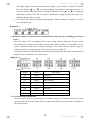
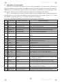
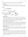
1
SM-8800 Multi-Function Electronic load (10 in 1) Hardware User’s manual Auto/ATE Version Sun Moon Technology Corp. ͟ᚹ̄ࡊԫѣࢨ̳Φ Table of Contents 1. General information 1-1 Standard configuration (Page2) 1-2 Specification (Page2) 1-3 Temperature protection (Page 3) 1-4 Front panel description (Page4) 1-5 Rear panel description (Page5) 2. Installation 2-1 SM-8800 power cord connection (Page6) 2-2 SM-8800 AC line connection (during self-coupling transformer adapted) (Page6) 2-3 SM-8800 connection with S.P.S. (Page7) 2-4 SM-8800 connection with oscillograph (Page7) 2-5 SM-8800 rear panel I/O Port connection with external control switch (Page7) 3. Operation panel description 3-1 Front panel description (Page11) 3-2 Display window description (Page12) 3-3 Rear panel description (Page13) 3-4 Keypad I1 ~ I10 setting and operation (Page14) 3-5 Read the result of AC Power Meter under manual operation mode (※Only the model containing power meter works) (Page15) 3-6 Start the button function (Page 15) 4. Automatic test description 4-1 Test items specification (Page16) 5. Internal parameter Setting 5-1 Shift+A: Select Manual or Auto operation mode (Page21) 5-2 Shift+B: Set total test channels (Page24) 5-3 Shift+C: Set Auto- test parameters (Page25) 5-4 Shift+D: Set other shared parameters (Page33) 5-5 Shift+E: Fast set current in I1~I10 and maximum and minimum of voltage (Page41) 6. Deletion and Reset of machine parameters 6-1 Deletion and Reset of machine parameters, OPP retaining setting, and information setting by downloader (Page 45) 2010/9/20 English Ver 1.37 -1- ͟ᚹ̄ࡊԫѣࢨ̳Φ ͟ᚹ̄ࡊԫѣࢨ̳Φ 1. Introduction SM-8800 is a multi-function electronic load machine designed for every kind of S.P.S. It especially provides departments like production, examination or development with easy manipulation board displaying complete information. SM-8800 focuses on ATX Power and strengthens test function so users can test a whole ATX Power once. We concern the hardwork of operators for their long working hours. Therefore, SM-8800 displays bright numbers and English words. In automatic version, only need to press “OK”. This complete and multi-function design offers operators a clean workstation. 1-1 Standard packing Name Unit Number Model: SM-8800 mainframe Pcs 1 Power cord (U.S. type) Pcs 4P socket Model Unit Number SM-8800 manual Pcs 1 2 BNC cable (curved) Pcs 2 Pcs 3 ATX-6pins Pcs 1 ATX-8pins socket Pcs 1 ATX-24pins Pcs 1 Fuse10A(5x20mm) Pcs 3 Fuse 10A (2x20mm) Pcs 3 Chuck tightener of BNC line Pcs 3 Airline socket Pcs 1 1-2 Specification DC part channel VA volt 80V current 0~40A watt 360W VB VE VG VH VC VD VF VI VJ 0V ~ 40V 0 ~ 60A 0 ~ 40A 300W 360W 0 ~ 4A 0~8A 40W 0 ~ 20A 180W DC voltage error range Standard Full scale voltage Error Range 40V 40V + 0.3% + 2C channel Full scale current Error Range VA 40A + 1 % + 2C VB 60A + 1 % + 2C VC 4A + 1 % + 2C VD 4A + 1 % + 2C VE 60A + 1 % + 2C VF 8A + 1 % + 2C VG 40A + 1 % + 2C VH 40A + 1 % + 2C VI 20A + 1 % + 2C VJ 20A + 1 % + 2C DC current error range -2- ͟ᚹ̄ࡊԫѣࢨ̳Φ ͟ᚹ̄ࡊԫѣࢨ̳Φ Timing measurement precision Test Item Maximum Error Fange Test Frequency POWER GOOD 999.9mS + 0.5% + 2C POWER FAIL 999.9mS + 0.5% + 2C SET UP 2999.9mS + 0.5% + 2C HOLD ON 2999.9mS + 0.5% + 2C ON RING 9 1uS OFF RING 9 1uS AC part Line AC Input Internal AC source 110V+10% 230V+10% Frequency 50/60HZ Fuse 2A (5 x 20 mm) 2A (5 x 20 mm) Maximum of power consumption 100W Line AC + Maximum of S.P.S. power consumption (External Source Input) 2020~3020W AC source 0 ~ 265V Frequency 30 ~ 150HZ Fuse 10A (5 x 20 mm) Max AC voltage (RMS) 270V + 0.5% + 2C Max AC current (RMS) 10A + 0.5% + 2C Outline Dimension 450 x 165 x 490 mm(excluding handle and foot rubber) Weight 22KGS Annotation 1 Version Ver3.00 Ver4.00 Ver3.01 Ver4.01 Line AC + Maximum of S.P.S. power consumption 2020W 3020W 1-3 Temperature protection After SM-8800 is booted, the fan is at low speed. At this time, if the temperature increases above 55℃, the fan changes into high speed. If the temperature decrease below 40 ℃ at high speed, the fan will change into low speed. -3- ͟ᚹ̄ࡊԫѣࢨ̳Φ ͟ᚹ̄ࡊԫѣࢨ̳Φ !Front panel! -4- ͟ᚹ̄ࡊԫѣࢨ̳Φ ͟ᚹ̄ࡊԫѣࢨ̳Φ Rear Panel! -5- ͟ᚹ̄ࡊԫѣࢨ̳Φ ͟ᚹ̄ࡊԫѣࢨ̳Φ 2. Installation 2-1 SM-8800 and power cord connection Please take out SM-8800 from the package. You can see a selection switch. (Please elevate SM-8800 so that you can see the selection switch of 110V /230V) If indoor voltage is AC 230V, please switch “Line Select” to 115V. Insert AC Power cord into the socket of SM-8800 rear panel “Line AC Input”. Likewise, insert the other end into the indoor socket. Ground “F.G.” of SM-8800 rear panel so that it can prevent operaters from electric shock due to electric leackage. Refer to figure 2-1. Figure 2-1 Power cord and F.G terminal connection 2-2 SM-8800 and external AC source (Self-coupling transformer) connection : Switch “Source Select” to “EXT” on SM-8800 rear panel. Refer to figure 2-2. Insert the airline socket connected cord into airline socket “EXT Source Input” to connect IN-2 and COM to output of self-coupling transformer. Insert output of self-coupling transformer into the indoor socket. Figure 2-2: UUT and external AC source connect to instrument -6- ͟ᚹ̄ࡊԫѣࢨ̳Φ ͟ᚹ̄ࡊԫѣࢨ̳Φ 2-3 SM-8800 and S.P.S. connection : Take out AC power cord from the appendix. Refer to figure2-2. Use AC power cord to connect “To S.P.S.” socket of SM-8800 rear panel and the socket of S.P.S. AC power input. Refer to figure 2-4. Insert the output of S.P.S. DC into the socket of SM-8800 front panel in the lower left side (such as ATX, ATX-20pin or 4P socket) Figure2-3 Circuit diagram of AC portion 2-4 SM-8800 and Oscilloscope connection Use the BNC cable in the appendix to connect BNC socket of SM-8800 and Oscillascope. Figure2-4 Oscillograph and output of S.P.S. connection 2-5 SM-8800 “I/O Port” (Input/Output) signal and external control circuit connection 2-5-1 Input signal and connection of external switch on I/O port of SM-8800 rear panel. Arrange a control circuit. (Refer to figure 2-5-1a) Connect control switch (like button of pedal) with related circuit on “R.C.” and “R.C. COM” ends of I/O port on SM-8800 rear panel. (Connection mistake may damage the internal circuit of SM-8800.) Figure 2-5-1b is the output circuit of “R.C. COM” ends on I/O Port” -7- ͟ᚹ̄ࡊԫѣࢨ̳Φ ͟ᚹ̄ࡊԫѣࢨ̳Φ Figure2-5-1a External control switch connection Figure5-2-1b SM-8800 and R.C. external control switch connection 2-5-2 OUT1~OUT4 of I/O Port and external device connection Please arrange an external control circuit designed according to your need. (Refer to Figure2-5-2.) Connect the circuit to the terminals, OUT1, OUT2, OUT3, OUT4 and COM of I/O Port (Refer to Figure2-5-2a.) (Connection mistake may damage the internal -8- ͟ᚹ̄ࡊԫѣࢨ̳Φ ͟ᚹ̄ࡊԫѣࢨ̳Φ circuit of SM-8800.) Figure 2-5-2b is output circuit of Out1~4 and COM in I/O Port in SM-8800 rear panel. Figure2-5-2a SM-8800 and Out 1~4 external control connection Figure2-5-2b Output circuit of Out1~4 in “I/O Port” socket on rear panel and “COM” terminal -9- ͟ᚹ̄ࡊԫѣࢨ̳Φ ͟ᚹ̄ࡊԫѣࢨ̳Φ 2-5-3 PASS/FAIL output terminals of I/O Port and external control device connection Please make a control circuit that is designed according to your need for external device, the circuit in Figure2-5-3is for your reference. Connect the circuit and I/O port as shown in Figure2-5-3. Please pay attention in this process, wrong connection may damage the instrument. Figure2-5-3a I/O Port and external device connection Figure2-5-3a Output circuit of “PASS/FAIL” in I/O Port socket on rear panel and “PASS/FAIL COM” terminal -10- ͟ᚹ̄ࡊԫѣࢨ̳Φ ͟ᚹ̄ࡊԫѣࢨ̳Φ 3 Operation panel description 3-1 Keypad of front panel description : 1. Power: AC on/off switch for SM-8800 2. I1/I6 ~ I5/I10:There are 10 selections of pre-set load current and power maximum and minimum. (Selections can be extended to 20 in automatic test mode.) When the switch is on, the mode I1~I5 is default. Press keyboard “Shift” to switch to I6~I10. When LED light twinkles, press the button “I6~I10 to select load you need. Shift+I1 can be combination button of dynamatic load. 3. Amp:Set and read the current 4. V-Hi / V-Lo:When V-Hi is light, set and read the voltage maximum.When V-Lo LED is light, set and read the voltage minimum. 5. Vol / Watt: When Vol is light, the latest voltage is displayed. When Whatt is light, DC power is displayed. (Maximum of power displayed is 1590W.) 6. PSON: This is a switch especially designed for ATX Power. When S.P.S. AC is ON and PSON is light, every channel of S.P.S. outputs. When PSON is not light, only +5VSB(VF) keeps outputting. Other channels stop outputting. 7. Shift:This is used for combination button. The way is Shift + another button. The way of operation is keep pressing Shft and then another button. Then, leave two buttons at the same time. For example, Shift + A/6 is keep pressing Shift and then A/6. Finally, leave two buttons at the same time. 8. A/6 ~ F/9、G /▲、H /▼:Short test of VA~VH (Short test of VG and VH needs to be set at channel 8, 10 so that the displayed voltaged can be operated.) Combination buttons of setting functions are below. (Only pressing the buttons in the standby mode works out.) Shift+A: Switch manual test and automatic. Shift+B: Set channels. Shift+C: Set parameters and edit automatic test. Shift+D: Set test parameters. Shift+E: Fast set current I1~ I20 and voltage maximum and minimum. Shift+F: Enter the password。 9. OPP: Over power Protection test (Maximum is 2260W~3260W)。 10. On/ Esc: Turn on S.P.S. AC Power (Output socket is To S.P.S on the rear panel) and set multi-function buttons. 11. Off / Enter:Turn off S.P.S. AC power and set multi-function buttons. When enter Shift+B, Shift+B, Shift+C, Shift+D, Shift+E or Shift+F to set functions, press this button to save all changed parameters and back to the standby mode. 12. ◄、►: Control circulating movement of display window. 13. ▲/Page Up、▼/Page Down:To increase or decrease the setting, these buttons can be used as short button of VG and VH at Vol gear. Move to another page with Shift as combination button such as “Shift+ Page Up” and “Shift+ Page Down”. 14. Waveform Monitor:6- band switch. Through selecting BNC connection, waves of two channels to osillograph. Refer to figure2-4. -11- ͟ᚹ̄ࡊԫѣࢨ̳Φ ͟ᚹ̄ࡊԫѣࢨ̳Φ 3-2 Display window description (Refer to front panel) 1. MESSAGE / VI:To display voltages comparison, the result of time test, the information and result of automatic test, DC overall power, setting desceiption of the page, and the expansion of the 9th channel (VI) load. 2. VALUE / VJ:To display voltages comparison, the result of time test, the information and result of automatic test, DC overall power, setting desceiption of the page, and the expansion of the 10th channel (VI) load. 3. VA、VB、VC、VD、VE、VF、VG、VH、VI、VJ:To display voltages, currents, powers and setting information for each channel. 4. VG:To display the AC voltage and expansion of channel 7th load. 5. VH:To display the AC current and expansion of channel 8th load. 6. When the power is on, our company name turns up on the left screen. Refer to Figure3-2a. Figure3-2a Later on, machine model and type turn up on the left screen. If the machine is a automatic type (AUTO), model and type will be displayed on the screen according to total amount of channel “Shift+B”. Refer to Figure3-2b, Figure3-2c and Figure3-2d. Figure3-2b (6-channel automatic type) Figure3-2c (8-channel automatic type) Figure3-2d (10-channel automatic type) If the instrument is ATE (Control by computer) type, we provide 3 types such as 6 channels, 8 channels and 10 channels in one mainframe, the display messages are shown as Figure3-2e Figure3-2f and Figure3-2g as following: Figure3-2e (e.g. ATE 6-channel was set up) -12- ͟ᚹ̄ࡊԫѣࢨ̳Φ ͟ᚹ̄ࡊԫѣࢨ̳Φ Figure3-2f (ATE 8-channel type) Fiugure3-2g (ATE 10-channel type) 7. After machine model and type are displayed, machine is in the standby mode. Refer to figure 3-2h, figure3-2i or figure3-2j. (Please refer to 5-2 parameters setting.) Standy mode means the moachine is: AC OFF S.P.S. does not output voltage to the machine. One of LED lights (in I1/I6~I5/I10) blinks and one of lights (in Amp, Vol, Watt, V-Hi or V-Lo) blinks. 8. Three figures below are manual standby modes. According to total amount setting of channel “Shift+B”, figure 3-2h, figure 3-2i or figure3-2j is displayed. If want to switch to standby mode, refer to 5-1. Figure3-2h (e.g. 6-channel was set up) Figure3-2i (e.g. 8-channel was set up) Figure3-2j (e.g. 10-channel was set up) 3-3 Rear panel description 1. To S.P.S.:To provide AC power for S.P.S. -13- ͟ᚹ̄ࡊԫѣࢨ̳Φ ͟ᚹ̄ࡊԫѣࢨ̳Φ 2. Line AC Input:This is input socket of machine power. When “Source Select” is selected at “INT”, AC power of S.P.S. is provided by this. 3. Line: To protect power fuse of machine. 4. Line Select:Select input voltage of AC power. The place of switch is under the base of Line Select→Under Base. 5. Source Select:Select AC source for S.P.S, When INT is selected, AC source of S.P.S. is provided by Line AC Input. When EXT is selected, AC source of S.P.S. is provided by EXT Source Input. (In manual mode, only IN-2 and COM can input AC line voltage. Refer to Figure2-2. In auto mode , 3 external AC inputs are available) 6. EXT Source Input:AC source input provided by external source. 7. AC-2:External AC source fuse input by “IN-2". 8. AC-1、AC-3:External AC source fuse input by “IN-1”and “IN-3”. 9. F.G:Grounded terminal of the machine can protect operators from electric shock. 10. RS-232 Port:Socket connected with the computer. 11. I/O Port:This can output and input various signals. Each description is below: Output:To send a 4-bit Hi or Low signal to control external devices: PASS/FAIL:An automatic test is completed. When the test result is PASS, a pulse signal is sended from this socket. When the test result is FAIL, two pulse signals are sended. (Refer to Figure3-3) This signal can be used to control external devices. Figure3-3 Remote Control: The socket to connect external control Switch. In auto test mode, you can press the external control Switch to make continual test for next UUT, as shown in 2-5 Connection. 3-4 Setting program to I1 ~ I10 under Stand-to Mode (e.g. Shift+B : 6 channels was set up ) 1. Press the button I3 in standby mode (I3 is light.) to start setting I3 current and voltage maximum and minimum. 2. Press the button Amp (Amp is light) to set current of 6 channels DC so the number in channel VA blinks. Press the button “▲” or “▼” can change the current of channel VA. Press the button “►” to switch to channel VB so the number in channel VB blinks. Press the button “▲” or “▼” can change the current of channel VB. The rest may be deduced by analogy. If press the button “◄” , blinking channel will move back. 3. Press the button “V-Hi” (V-Hi is light.) to display the current of 6 channelsVA~VF DC and judge voltage maximum and minimum setting, so the number in channel VA blinks. Press the button “▲” or “▼” to change channel VA maximum. Press the button“►” to switch to channel VB so the number in channel VB blinks. Press “▲” or “▼” to change the maximum of channel VB. The rest may be deduced by analogy. If press the button “◄”, blinking channel will move back. 4. Press the button “V-Low” (V-Low is light.) to display the current of 6 channelsVA~VF DC -14- ͟ᚹ̄ࡊԫѣࢨ̳Φ ͟ᚹ̄ࡊԫѣࢨ̳Φ and judge voltage minimum and minimum setting, so the number in channel VA blinks. Press the button “▲” or “▼” to change channel VA minimum. Press the button“►” to switch to channel VB so the number in channel VB blinks. Press “▲” or “▼” to change the maximum of channel VB. The rest may be deduced by analogy. If press the button “◄”, blinking channel will move back. 5. Set current and voltage maximum and minimum. When setting is completed, it will be saved automatically.. Figure3-4 3-5 Read test result of AC power meter in manual mode (Only the type including power meter works) Press the button “On” in standby mode to start testing related parameters of power meter. Press Shift+I5 to display 8 test results of power meter. (Refer to figure 3-5 and table 3-5.) AC power of different load can be read by switching I1~I10. Press another button to quit this window. If need to read parameters of AC power meter, press Shift+I5. Press Shift+I4 to start Vp-Hold and Ip-Hold function to remain VA and VB in maximum of Vp and Ip in test result mode of AC power meter. Figure3-5 Table3-5 Channel VALUE Description VA FREQ VB VP AC peak value VC WATT Power (RMS) VG VRMS AC voltage(RMS) VH IRMS AC current(RMS) VD EFFI Efficiency VE IP VF EQUA Frequency AC voltage peak value Power factor 3-6 To start button lock function Press the button Shift+I2 to start button lock function. Only AC On and AC Off works. Others operation fails. If press the button Shift+I2, button lock function can be turned off and back to the original mode. -15- ͟ᚹ̄ࡊԫѣࢨ̳Φ ͟ᚹ̄ࡊԫѣࢨ̳Φ 4. Automatic test description There are 23 automatic test items for users to edit “test program”. 50 items can be edited in test program (including action and test items.)When the test starts, test programs are operated by sequence. When all tests are completed, it displays PASS or FAIL and the information of test results can be read. When S.P.S. fails to boot, the machine stops testing and the screen displays S.P.S. Down. This is an automatic test system of power supply. All test programs can be edited and operated according to users’ need. Items and numbers are provided by automatic test system. (No.0, No.13~19 and No.20 and 23 are action items; No.1~12 and No.20 and 21 are test items) ※ In test report, only test items have test results. No test result for action items. NO Test items Name of test items Simple description 0. END END Test is completed. 1. LOAD Loading Test Static load test 2. SETUP SetUp Time Test Time test of stable booting 3. PG. Power Good Time Delay time test of Power Good signal 4. ON.RING. ON Ring Times Ring times of Power Good from Low to High 5. HOLD.ON Hold-On Time Time test of stable shutting down 6. PF Power Failure Time Advanced time test of unsuccessful Power Good signal 7. OF.RING. OFF Ring Times Test Ring times of Power Good from High to Low 8. OPP Over Power Protect Test Protection test of over power 9. OCP Over Current Protect Test Protection test of over current 10. WAIT Wait Waiting for test 11. SHORT Short Protect Test Short protection test 12. PS OFF.T. Ps Off Test Shutting down signal test of ATX Power 13. LINE.IN Line In Select the AC source for S.P.S. 14. AC ON AC ON Turn on the AC source of To S.P.S socket 15. AC OFF AC OFF Turn off the AC source of To S.P.S. socket 16. PS ON PS ON Short of PS input toward ground 17. PS OFF PS OFF Open of PS input toward ground 18. OUTPUT OutPut To output 4-bit signal Hi or Low. The first bit is the test result of former one. 19. LOOP Loop To rtepeat testing from the first item of program 20. RISE Rise Time Test Time test of stable booting 21. AC METER AC parameter test Parameters judgement of AC power meter. (Only the type with power meter works.) 22. AC.HOLD AC Meter Hold On To start Hold On function of AC power meter 23. HOLD.OF AC Meter Hold Off To stop Hold On function of AC power meter -16- ͟ᚹ̄ࡊԫѣࢨ̳Φ ͟ᚹ̄ࡊԫѣࢨ̳Φ 4-1 Test items specification (Item 2~7 are the part of time test. Refer to Figure4-1a) 0. END The test is completed. AC OFF and PsOff are controlled. Test result is displayed. 1. Loading Test To wait for Steady time according to the load set in Ix. (Refer to 5-3-2) Test value is input voltage of each channel. If V-Hi>test value>V-Lo, the test result will be PASS. If not, the result will be FAIL. Figure4-1a 2. Setup Time Test Boot the machine according to the load set in Ix. Zero the timer when input power is turned on. (AC phase is at 0 degree) and start timing at the same time. Keep testing +5 voltage of voltage terminal whether it equals to the voltage set by VREF or not. If voltages are the same, voltages of the timer will be recorded. This is the test value of Setup Time. If the maximum of Setup Time>test value>the minimum of Setup Time, the test result will be PASS. If not, the result will be FAIL. 3. Power Good Time Test (P.G. Time Test) Boot the machine according to the load set in Ix and keep testing +5 voltage of voltage terminal whether it equals to the voltage set by VREF or not. If voltages are the same, zero the timer and start timing at the same time. When Power Good signal of S.P.S. changes from Low to High, the value of the timer is recorded. This is the test value of P.G. Time. If the maximum of P.G. Time>test value>the minimum of P.G.Time, the test result will be PASS. If not, the result will be FAIL. 4. ON Ring Times Test Boot the machine according to the load set in Ix. The machine keeps monitoring Power Good signal of S.P.S. output changed from Low to High. The valu is recorded. This is the test value of P.G. Ring. If the maximum of P.G. Ring>test value>the minimum of P.G. Ring, the test result will be PASS. If not, the result will be FAIL. 5. Hold-On Time Test Boot the machine according to the load set in Ix and turn off input power of S.P.S. Zero the timer when S.P.S. power is off. (AC phase is at 0 degree)Then, the machine starts timing at the same time and keeps testing +5 voltage of voltage terminal whether it equals to the voltage set by VREF or not. If voltages are the same, voltages of the timer will be recorded. This is the test value of Hold-On Time. If the maximum of Hold-On Time>test value>the minimum of Hold-On Time, the test result will be PASS. If not, the result will be FAIL. -17- ͟ᚹ̄ࡊԫѣࢨ̳Φ ͟ᚹ̄ࡊԫѣࢨ̳Φ 6. Power Fail Time Test (P.F. Time Test) Boot the machine according to the load set in Ix and turn off input power of S.P.S. Zero the timer when Power Good signal of S.P.S. output changes from High to Low. Then, the machine starts timing at the same time and keeps testing +5 voltage of voltage terminal whether it equals to the voltage set by VREF or not. If voltages are the same, voltages of the timer will be recorded. This is the test value of P.F. Time. If the maximum of P.F. Time>test value>the minimum of P.F. Time, the test result will be PASS. If not, the result will be FAIL. 7. OFF Ring Times Test Boot the machine according to the load set in Ix and turn off input power of S.P.S. The machine keeps monitoring the times of S.P.S. output Power Good signal changeing from High to Low. Then, it records voltages. This is the test value of P.F. Ring. If the maximum of P.F. Ring>test value>the minimum of P.F. RIng, the test result will be PASS. If not, the result will be FAIL. 8. Over Power Protection Test Boot the machine according to the current set in OPP Step I. The current increases load. Every time it climbs it stops for a while (Step T). The machine recurds the power. (Input voltage of each channel from voltage terminal x the last current) If set SET OPPNOL in chapter 6, the last power will be remained. If select SET OPPMAX, the machine will judge whether the power is higher than the former one or not and remains the higher one. When the current set by OPP End I is reached or down protection occurs, the machine stops current from climbing higher. Power maximum of S.P.S. is recorded. This is the test value of OPP. If the maximum of OPP>test value>the minimum of OPP, the test result will be PASS. If not, the result will be FAIL. During the test, if the maximum of OPP≦+5VSB voltage≧the minimum of OPP or load current of any channel reaches the current set by End Current and down protection of S.P.S. does not occur, the test value will be recorded as 0. The machine stops testing OPP and records this test result as FAIL. After OPP test is completed, select one way to turn off S.P.S. according to the setting of Shift+C amtomatic test in editing page OPTION 9. Over Current Protection Test Boot the machine according to climbing channels selected by OCP1 and OCP2 (Refer to 5-3-11 for more detailed setting) to select setting current of corresponding channel in OCP Step I. The current has increased load since the machine is turned on. Every time it climbs it stops for a while (Step T). The machine records the current. When the current set by OCP End I is reached or down protection occurs, the machine stops current from climbing higher. S.P.S current maximum during down protection is recorded. This is the test value of OCP. Judgement for one channel selected: If the maximum of OCP≧Test value≧ the minimum of OCP, the test result will be PASS. If the test value>the maximum of OCPor the test value<the minimunm of OCP, the test result will be FAIL. Judgment for two channels selected: The judgement for OCP1 and OCP2 is the same as the judgement for one channel selected. However, the test result of OCP1 and OCP must be PASS so the judgement for two channels sleceted may be PASS. If not, the result will be FAIL. After OCP is completed testing, select one way to turn off S.P.S. according to the setting of Shift +C -18- ͟ᚹ̄ࡊԫѣࢨ̳Φ ͟ᚹ̄ࡊԫѣࢨ̳Φ automatic test in editing page OPPTION. 10. Wait Boot the machine (according to the load set in Ix) and the program stops operating to wait for operators to adjust the voltage, read voltage ripple, check vibration test and test materials and terminals. When press the button AC ON, read input voltage of voltage terminal for each channel. If V-Hi≧Votage≧V-Lo and P.G. signal is in normal range, the test result will be PASS. If Voltage> V-Hi, Voltage<V-Lo or P.G. signal is abnormal, the test result will be FAIL. 11. Short Protect Test Boot the machine according to the load set in Ix. Load short selected by short option (Option) checks whether it is down or not. (To check the voltage set in DOWN+V of Shift+D, ATX/AT set in Shift+C and Short.M check) If it is down, PASS will be recorded. If not, PASS will be recorded. When Short Protect Test is completed, select one way to turn off S.P.S. according to the OPTION setting Shift+C automatic test program in editing page. 12. Ps Off Test Boot the machine (according to the load set in Ix) and action Ps Off is operated. If +5VSB(VF) of S.P.S. remains in the range between maximum and minimum. The rest voltages all fall to the setting voltage set by DOWN V so Ps Off function is normal and judged as PASS. If not, it will judged as FAIL. 13. Line In (Operation item, no result during the test) Select external power for providing to S.P.S. First, turn off AC output and then the relay attracted by the corresponding one. When finish selecting, the following test uses this as power of S.P.S. Relay stops attracting till Line In Test is selected again and test is completed. 14. AC ON(Operation item, no result during the test) Set load and select AC source output of “To S.P.S.” on the rear panel as ON. 15. AC OFF(Operation item, no result during the test) Select AC source output of “To S.P.S.” on the rear panel as OFF. 16. PS ON(Operation item, no result during the test) Set load and PS ON on input panel grounds as short. 17. PS OFF(Operation item, no result during the test) PS ON on input panel grounds as open. 18. OutPut(Operation item, no result during the test) The machine sends a Hi or Low control signal of 4-bit from “Output1~4” of I/O Port on the rear panel. 19. Loop(Operation item, no result during the test) The machine repeats testing and tests again from the first item of test program. When test is completed, next item is operated. 20. Rise Time Test (DC/ rise time) Set Vt and V1(Refer to 5-4-1) before AC power is ON. Zero the timer and boot the machine (according to the load set in Ix). The machine keeps checking whether Vt equals V1 ot not after S.P.S. is turned on. When Vt=V1, it starts timing, set V2 and keeps checking whether Vt equals V2 or not. If Vt=V2, it stops timing and time of timer is recorded. (Refer to figure4-1b) This is the test value of Rise Time. If the maximum of Rise Time≧Test value≧The minimum of Rise Time, the test result will be PASS.If Test value>The maximum of Rise Time or Test value<The minimum of Rise Time, the -19- ͟ᚹ̄ࡊԫѣࢨ̳Φ ͟ᚹ̄ࡊԫѣࢨ̳Φ result will be FAIL. 圖 4-1b 21. AC Meter Test )※!Ju!jt!pomz!bwbjmbcmf!voefs!uif!BD!qpxfs!nfufs!jt!dpogjhvsfe*! After AC power is on, AC power meter tests the following items: 1. AC frequency 2. AC peak voltage(PICK) 3. AC power (RMS) 4. AC voltage(RMS) 5. AC current (RMS) 6. Efficiency 7. AC peak current(PICK) 8. Power factor 4. AC Meter Hold On!)※Only the type with power meter has this function* Turn on Hold On function of AC power meter to start Vp-Hold and Ip-Hold function to read the maximum Vp and Ip. 5. AC Meter Hold Off!)※Only the type with power meter has this function* Turn of Hold On function of AC power meter turn back to normal test function of AC power meter. -20- ͟ᚹ̄ࡊԫѣࢨ̳Φ ͟ᚹ̄ࡊԫѣࢨ̳Φ 5 Condition and parameter setting 5-1 Shift+A:Switch manual test SM-8800 Auto model: Press the button Shift+A during standby mode in manual mode. If LED light Auto on the front panel (Refer to figure 5-1a) and a number shows on the upper left side of the monitor, (There are 10 channels of test programs. This number indicates which number users are using) (Figure 5-1c, figure5-1d or figure5-1e are showed according to a channel total setting in Shift+B) the machine enters automatic test. Press the button Shift +▲ or Shift+▼. Select automatic test program I1~I10 and press the button Shift+A, the number on the monitor vanishes back to manual mode. (There is no number on the upper left side after LED light Auto is not light) SM-8800 ATX model: Press the button Shift+A during standby mode in manual mode. If LED light Auto on the front panel (Refer to figure 5-1a) and a number shows on the upper left side of the monitor, (This number indicates which number users are using) (Figure 5-1c, figure5-1d or figure5-1e are showed according to a channel total setting in Shift+B) the machine enters automatic test. Press the button Shift +▲ or Shift+ ▼. Select automatic test program I1~I10. If LED light Auto on the front panel blinks and there is no number on the upper left side of the monitor, the machine will connect the computer. Users can operate the computer to proceed automatic test. Press the button Shift+A, the number on the monitor vanishes back to manual mode. (There is no number on the upper left side after LED light Auto is not light) Figure5-1a Figure5-1b Test program 1—10 sketch-map: Figure5-1c (e.g. 6- channel window message) -21- ͟ᚹ̄ࡊԫѣࢨ̳Φ ͟ᚹ̄ࡊԫѣࢨ̳Φ Figure5-1d (8 channels are set.) Figure5-1e (10 channels are set.) 5-1-1 Press the button AC ON on the front panel in automatic test mode to start automatic test. When the test is completed, the monitor shows 3 kinds of results. 1. S.P.S. d.n.:This represents booting fails. (Refer to the figure 5-1-1a) (Refer 5-4-5 for more detailed specification) Press Enter to quit. Check S.P.S., read (or correct) the setting and test again. Figure5-1-1a 2. PASS:This represents test is normal. (Refer to figure 5-1-1b). Then, the machine sends a pulse signal from PASS/FAIL of I/O Port on the rear panel to control external devices. Figure5-1-1b Operate the buttons C/8 and D to browse test result for each test item. (Figure 5-1-1c, figure 5-1-1d or figure5-1-1e is showed according to channel total setting in Shift+B.) Figure5-1-1c (6 channels are set) Figure5-1-1d (8 channels are set) Figure5-1-1e (e.g. 10-channel window message) -22- ͟ᚹ̄ࡊԫѣࢨ̳Φ ͟ᚹ̄ࡊԫѣࢨ̳Φ 3. FAIL: This represents test is abnormal. (Refer to figure 5-1-1f) and shows the test number of PASS/FAIL. Then, the machine sends a pulse signal from PASS/FAIL of I/O Port on the rear panel to control external devices. Figure5-1-1f Operate the buttons C/8 and D to browse test result for each test item. (Figure 5-1-1c, figure 5-1-1d or figure5-1-1e is showed according to channel total setting in Shift+B.) Operate the buttons ▲ and ▼ to browse test result of FAIL item. (Figure 5-1-1g, figure 5-1-1h or figure5-1-1i is showed according to channel total setting in Shift+B.) Figure5-1-1g (6 channels are set.) Figure5-1-1h (8 channels are set.) Figure5-1-1i (10 channels are set.) 5-1-2 Refer to the figure below for checking time of short test: T1 represents the length of short signal sended. T2 represents the length of short check. -23- ͟ᚹ̄ࡊԫѣࢨ̳Φ ͟ᚹ̄ࡊԫѣࢨ̳Φ If there is Short Protect Test in automatic test program when test result of Short Protect Test items is browsed, VALUE will display the wrong code. Refer to 3 figures below. Meaning for each code:”0” represents test is normal. “1” represents T2 Time is judged wrong. “2” represents T3 time is judged wrong. 3 represents T2 and T3 time is judged wrong. “4” represents VF is not in the range of maximum and minimum. (Figure5-1-1j, Figure5-1-1k or Figure5-1-1l is showed according to a channel total setting in Shift+B.) Figure5-1-1j (6 channels are set.) Figure5-1-1k (8 channes are set.) Figure5-1-1l (10 channels are set.) When the test is completed, press AC ON or control switch on the external of the machine (Refer to 3-3) Continue testing next S.P.S. Power. 5-2 Shift+B:Channel total amount setting. (It only works in standby mode.) (The setting is used by manual and automatic mode) SET LOAD—N: Set total amount of used channels. Press “▼” or “▲” to select 6 channels, 8 channels or 10 channels. Table5-2 Channel VALUE Max channels Min channels Form VA LOAD 10 6 Press “Shift+PageDown” to turn off channels unused. For example, there is one set as 8 channels. Channel VC and VH are not used and “1” is set for channel. Press “Enter” to quit. Close the window of VC and VH in the standby mode. The window of voltage maximum and minimum is closed as well. Though there is the setting in Shift+B, it can be ignored. -24- ͟ᚹ̄ࡊԫѣࢨ̳Φ ͟ᚹ̄ࡊԫѣࢨ̳Φ 5-2-1 When 6 channels are set, channel VA~VF display 6 channels of voltage. Channel VG displays AC-V. Channel VH displays AC-I. Refer to the figure below. 5-2-2 When 8 channels are set, channel VA~VH displays 8 channels of voltage. (Refer to figure 5-2-2a) Press the button “►” to display AC-V in VG in manual mode at voltage gear. It takes 2 seconds to display AC-I in VH. (Refer to VG and VH in figure 5-2-2b) and then the screen displays normally. (Refer to figure 5-2-2a) Figure5-2-2a Figure5-2-2b 5-2-3 When 10 channels are set, channel VA~VJ display 10 channels of voltage. (Refer to figure 5-2-3a) Press the button “►” to display AC-V in VG in manual mode at voltage gear. It takes 2 seconds to display AC-I in VH. (Refer to VG and VH in 5-2-3a.) Press the button ”◄” to display voltage condition of 10 channels for 2 seconds in manual mode at voltage gear. (Refer to VI and VJ in figure5-2-3c.) Then, the screen displays normally. Figure5-2-3a Figure5-2-3b Figure5-2-3c Setting is completed. Press the button Enter to save setting and quit back to standby mode.. -25- ͟ᚹ̄ࡊԫѣࢨ̳Φ ͟ᚹ̄ࡊԫѣࢨ̳Φ 5-3 Shift+C: Set auto-test parameters (It only works in standby mode) 5-3-1 CONF 1: Shift+C (Page 1) When S.P.S. is down in automatic test, judge voltage minimum of repeated booting. (Figure5-3-1a, figure5-3-1b or figure5-3-1c is showed according to total setting of channels in Shift+B.) Figure5-3-1a Figure5-3-1b v Figure5-3-1c RESET.V.:Voltage judgment of discharging for each channel (Refer to table5-3-1.) Start timing when directive AC ON is operated in auto-test. Check output voltage of S.P.S. whether it is lower than the setting or not to make sure S.P.S. finishes discharging or achieves the time setting of RETRY.T. to control action AC ON to test. (No judgment for channel VP when ATX/AT selection in table 5-3-2 is “1”.) Table5-3-1 RESET V value setting range: Channel VALUE Upper limit Lower limit VA RESET.V 9.99 0.00 VB RESET.V 9.99 0.00 VC RESET.V 9.99 0.00 VG RESET.V 9.99 0.00 VH RESET.V 9.99 0.00 VD RESET.V 9.99 0.00 VE RESET.V 9.99 0.00 VF RESET.V 9.99 0.00 VJ RESET.V 9.99 0.00 VI RESET.V 9.99 0.00 Form 5-3-2 CONF 2: Shift+C (Page 2)Shared parameters setting of manual and auto test. Figure5-3-2 -26- ͟ᚹ̄ࡊԫѣࢨ̳Φ ͟ᚹ̄ࡊԫѣࢨ̳Φ Table5-3-2 :To set up the auto test function parameter. Test channel VALUE Upper limit Lower limit VA RETRY.T 32.00(Sec) 00.00 VB STEADY 8.00(Sec) 0.000 VC ATX/AT 1 0 VG SHORT.M 1 0 VH AC/DC 1 0 VD SHORT.T 8.00(Sec) 0.30 VE READY.T 20.00(Sec) 0 form RETRY.T:Check output voltage of S.P.S. whether it is lower than RESET.V. or not (Refer to 5-3-1) or achieves the time setting to control action AC ON. (Unit: Second) STEADY:Test duration of each test item ATX/AT: S.P.S. is STX Power or AT Power. When ATX Power operates protection action (like OPP Test and Short Test), the voltage of +5VSB (VF) can not decrease due to down S.P.S. When ATX Power is set, the voltage of +5VSB (VF) is tested whether it is in the range between maximum and minimum. When ATX Power is set, the voltage of +5VSB (VF) is not checked. 0:AT 1:ATX SHORT.M:S.P.S. Short mode 0:The voltage doesn’t turn back. Turn off AC or PS ON switch to reboot S.P.S. after short. 1:Remove short to turn back to the normal voltage of S.P.S. AC/DC:Select a type for S.P.S. 0:S.P.S. is AC to DC. 1:S.P.S. is DC to DC. SHORT.T:Short time parameters The setting of short time (Unit: Second) READY.T:Delay time for booting When S.P.S. turns on AC source or PS ON (according to arrange of auto-test), the machine starts timing. When the time set in READY.T is arrived, the machine starts reading voltages. (Unit: second.) 5-3-3 CONF 3 Shift+C: (Page3) Parameters setting comparison of first channel in AC power meter. ※ There are 4 channels for parameters settings of maximum and minimum. (From page 3 to page 10) Table5-3-3 Channel Maximum VA VALUE 1.FREQ ㄩ 999.9 Minimum 1.FREQ ㄇ VB 1.VP ㄩ 999.9 1.VP ㄇ VC 1.WATT ㄩ 6500.0 1.WATT ㄇ VG 1.VRMS ㄩ 999.9 1.VRMS ㄇ VH 1.IRMS ㄩ 99.99 1.IRMS ㄇ -27- Form ͟ᚹ̄ࡊԫѣࢨ̳Φ ͟ᚹ̄ࡊԫѣࢨ̳Φ VD 1.EFFI ㄩ 110.0 1.EFFI ㄇ VE 1.IP ㄩ 99.99 1.IP ㄇ 1.EQUA ㄩ 1.EQUA ㄇ VF 1.100 1.FREQ ㄩ:Maximum of AC frequency in first channel 1.V P ㄩ:Maximum of AC voltage pick in first channel 1.WATT ㄩ:Maximum of AC power (RMS) in first channel 1.I-RMS ㄩ:Maximum of AC current effeciency (RMS) in first channel 1.EFFI ㄩ:Maximum of effeciency in first channel 1.I P ㄩ:Maximum of AC current pick in first channel 1.EQUA ㄩ:Maximum of Power Factor in first channel 5-3-4 Shift+C: Page 4 of Shift+C is to set up the lower limit of test items in AC Power Meter Table5-3-4 Channel Upper limit 1.FREQ ㄩ Lower limit VA VALUE 1.FREQ ㄇ VB 1.VP ㄇ 1.VP ㄩ 0.000 VC 1.WATT ㄇ 1.WATT ㄩ 0 VG 1.VRMS ㄇ 1.VRMS ㄩ 0 VH 1.IRMS ㄇ 1.IRMS ㄩ 0 VD 1.EFFI ㄇ 1.EFFI ㄩ 0 VE 1.IP ㄇ 1.IP ㄩ 0 Form 00.00 1.EQUA ㄇ 1.EQUA ㄩ VF 0 1.FREQ ㄇ:Minimum of AC frequency in first channel 1.V P ㄇ:Minimum of AC voltage pick in first channel 1.WATT ㄇ:Minimum of AC power (RMS) in first channel 1.I-RMS ㄇ:Minimum of AC current effeciency (RMS) in first channel 1.EFFI ㄇ:Minimum of effeciency in first channel 1.I P ㄇ:Minimum of AC current pick in first channel 1.EQUA ㄇ:Minimum of Power Factor in first channel 5-3-5 CONF 5 Shift+C (Page 5) Maximum parameters settings comparison of AC power meter for second channel -28- ͟ᚹ̄ࡊԫѣࢨ̳Φ ͟ᚹ̄ࡊԫѣࢨ̳Φ Channel Maximum VA VALUE 2.FREQ ㄩ 999.9 Minimum 2.FREQ ㄇ VB 2.VP ㄩ 999.9 2.VP ㄇ VC 2.WATT ㄩ 6500.0 2.WATT ㄇ VG 2.VRMS ㄩ 999.9 2.VRMS ㄇ VH 2.IRMS ㄩ 99.99 2.IRMS ㄇ VD 2.EFFI ㄩ 110.0 2.EFFI ㄇ VE 2.IP ㄩ 99.99 2.IP ㄇ Form 2.EQUA ㄩ 2.EQUA ㄇ VF 1.100 2.FREQ ㄩ:Maximum of AC frequency in second channel 2.V P ㄩ:Maximum of AC voltage pick in second channel 2.WATT ㄩ:Maximum of AC power (RMS) in second channel 2.I-RMS ㄩ:Maximum of AC current effeciency (RMS) in second channel 2.EFFI ㄩ:Maximum of effeciency in second channel 2.I P ㄩ:Maximum of AC current pick in second channel 2.EQUA ㄩ:Maximum of Power Factor in second channel 5-3-6 CONF 6 Shift+C (Page 6) Minimum parameters settings comparison of AC power meter for second channel 上限 下限 VA VALUE 2.FREQ ㄇ 2.FREQ ㄩ 0.0 VB 2.VP ㄇ 2.VP ㄩ 0.0 VC 2.WATT ㄇ 2.WATT ㄩ 0.0 VG 2.VRMS ㄇ 2.VRMS ㄩ 0.0 VH 2.IRMS ㄇ 2.IRMS ㄩ 0.00 VD 2.EFFI ㄇ 2.EFFI ㄩ 0.0 VE 2.IP ㄇ 2.IP ㄩ 0.00 組別名稱 欄位格式 2.EQUA ㄇ 2.EQUA ㄩ VF 0.000 2.FREQ ㄇ:Minimum of AC frequency in second channel 2.V P ㄇ:Minimum of AC voltage pick in second channel 2.WATT ㄇ:Minimum of AC power (RMS) in second channel 2.I-RMS ㄇ:Minimum of AC current effeciency (RMS) in second channel 2.EFFI ㄇ:Minimum of effeciency in second channel 2.I P ㄇ:Minimum of AC current pick in second channel 2.EQUA ㄇ:Minimum of Power Factor in second channel -29- ͟ᚹ̄ࡊԫѣࢨ̳Φ ͟ᚹ̄ࡊԫѣࢨ̳Φ 5-3-7 CONF 7 Shift+C (Page 7) Maximum parameters settings comparison of AC power meter for third channel Channel Maximum VA VALUE 3.FREQ ㄩ 999.9 Minimum 3.FREQ ㄇ VB 3.VP ㄩ 999.9 3.VP ㄇ VC 3.WATT ㄩ 6500.0 3.WATT ㄇ VG 3.VRMS ㄩ 999.9 3.VRMS ㄇ VH 3.IRMS ㄩ 99.99 3.IRMS ㄇ VD 3.EFFI ㄩ 110.0 3.EFFI ㄇ VE 3.IP ㄩ 99.99 3.IP ㄇ Form 3.EQUA ㄩ 3.EQUA ㄇ VF 1.100 3.FREQ ㄩ:Maximum of AC frequency in third channel 3.V P ㄩ:Maximum of AC voltage pick in third channel 3.WATT ㄩ:Maximum of AC power (RMS) in third channel 3.I-RMS ㄩ:Maximum of AC current effeciency (RMS) in third channel 3.EFFI ㄩ:Maximum of effeciency in third channel 3.I P ㄩ:Maximum of AC current pick in third channel 3.EQUA ㄩ:Maximum of Power Factor in third channel 5-3-8 CONF 8 Shift+C (Page 8) Minimum parameters settings comparison of AC power meter for third channel Channel Maximum 3.FREQ ㄩ Minimum VA VALUE 3.FREQ ㄇ VB 3.VP ㄇ 3.VP ㄩ 0.0 VC 3.WATT ㄇ 3.WATT ㄩ 0.0 VG 3.VRMS ㄇ 3.VRMS ㄩ 0.0 VH 3.IRMS ㄇ 3.IRMS ㄩ 0.00 VD 3.EFFI ㄇ 3.EFFI ㄩ 0.0 VE 3.IP ㄇ 3.IP ㄩ 0.00 Form 0.0 3.EQUA ㄇ 3.EQUA ㄩ VF 0.000 3.FREQ ㄇ:Minimum of AC frequency in third channel 3.V P ㄇ:Minimum of AC voltage pick in third channel 3.WATT ㄇ:Minimum of AC power (RMS) in third channel -30- ͟ᚹ̄ࡊԫѣࢨ̳Φ ͟ᚹ̄ࡊԫѣࢨ̳Φ 3.I-RMS ㄇ:Minimum of AC current effeciency (RMS) in third channel 3.EFFI ㄇ:Minimum of effeciency in third channel 3.I P ㄇ:Minimum of AC current pick in third channel 3.EQUA ㄇ:Minimum of Power Factor in third channel 5-3-9 CONF 9 Shift+C (Page 9) Maximum parameters settings comparison of AC power meter for forrth channel Channel Maximum VA VALUE 4.FREQ ㄩ 999.9 Minimum 4.FREQ ㄇ VB 4.VP ㄩ 999.9 4.VP ㄇ VC 4.WATT ㄩ 6500.0 4.WATT ㄇ VG 4.VRMS ㄩ 999.9 4.VRMS ㄇ VH 4.IRMS ㄩ 99.99 4.IRMS ㄇ VD 4.EFFI ㄩ 110.0 4.EFFI ㄇ VE 4.IP ㄩ 99.99 4.IP ㄇ Form 4.EQUA ㄩ 4.EQUA ㄇ VF 1.100 4.FREQ ㄩ:Maximum of AC frequency in fourth channel 4.V P ㄩ:Maximum of AC voltage pick in fourth channel 4.WATT ㄩ:Maximum of AC power (RMS) in fourth channel 4.I-RMS ㄩ:Maximum of AC current effeciency (RMS) in fourth channel 4.EFFI ㄩ:Maximum of effeciency in fourth channel 4.I P ㄩ:Maximum of AC current pick in fourth channel 4.EQUA ㄩ:Maximum of Power Factor in fourth channel 5-3-10 CONF 10 Shift+C (Page 10) Minimum parameters settings comparison of AC power meter for third channel Channel Maximum 4.FREQ ㄩ Minimum VA VALUE 4.FREQ ㄇ VB 4.VP ㄇ 4.VP ㄩ 0.0 VC 4.WATT ㄇ 4.WATT ㄩ 0.0 VG 4.VRMS ㄇ 4.VRMS ㄩ 0.0 VH 4.IRMS ㄇ 4.IRMS ㄩ 0.00 VD 4.EFFI ㄇ 4.EFFI ㄩ 0.0 -31- Form 0.0 ͟ᚹ̄ࡊԫѣࢨ̳Φ ͟ᚹ̄ࡊԫѣࢨ̳Φ VE 4.IP ㄇ 4.IP ㄩ 0.00 4.EQUA ㄇ 4.EQUA ㄩ VF 0.000 4.FREQ ㄇ:Minimum of AC frequency in fourth channel 4.V P ㄇ:Minimum of AC voltage pick in fourth channel 4.WATT ㄇ:Minimum of AC power (RMS) in fourth channel 4.I-RMS ㄇ:Minimum of AC current effeciency (RMS) in fourth channel 4.EFFI ㄇ:Minimum of effeciency in fourth channel 4.I P ㄇ:Minimum of AC current pick in fourth channel 4.EQUA ㄇ:Minimum of Power Factor in fourth channel 5-3-11 RUN1. 1 Shift+C (Page 11) (First auto-test program (according to the auto-test program numbers selected on stadby mode.),First test item) (Refer to the table below.) 50 pages are edited for auto-test programs. (Refer to the table below)Page 12~60 (Test item 2~50)and the frame on page 11 is the same as the setting. Channel VALUE Maximum Minimum VA Test item 21 0 VB LOAD 20 1 VC OPTION Test item of time: 1 SHORT: 9 LINE.IN: 3 LOOPT: 99 OUTPUT: 1111 AC.METR: 4 0 0 1 0 0000 1 VG OCP1 RISE 10 4 0 1 VH OCP2 10 0 VD DOWN M 1 0 VE V1 OPP、OCP、SHORT 16.00(V) 2 0.00(V) 0 VF V2 16.00(V) 0.00(V) Test item: Select auto-test items. LOAD: Select the test load to boot. OPTION:When select in the column of “Test item”: Time test item, SHORT, LINE.IN, LOOP, OUTPUT and AC.METR, there are some definitions and setting ways below. If the other items are selected, it will not work on OPTION. 1. When time test item is selected, it indicates the way to boot or shut down: Power on (Setup, PG, ON.Ring, Rise): 0=AC ON、1=Ps ON Power off (Hold-On、PF、OF.Ring):0=AC OFF、1=Ps OFF。 -32- ͟ᚹ̄ࡊԫѣࢨ̳Φ ͟ᚹ̄ࡊԫѣࢨ̳Φ 2. When SHORT test item is selected, it indicates channels of short: 0=VI, 1=VA, 2=VB, 3=VC, 4=VG, 5=VH, 6=VD, 7=VE, 8=VF, 9=VJ 3. When LINE.IN test item is selected, it indicates the numbers of external AC is selected:1=IN-1、2=IN-2、3=IN-3 4. When LOOP test item is selected, it indicates the items of repeated test. It is counted as “one time” from the first test item to LOOP test item. If “0” is set, test will repeat without stop until the button AC OFF is pressed. 5. OUTPUT test item is selected. There are 4 places number corresponding to the rear panel socket, “Out4”, “Out3”, “Out2” and “Out1”. When 0 is set, one signal Lo is output. When 1 is set, one signal Hi is output. Example: 0110 is set and outputs signal Lo, Hi, Hi from Out4~Out2 on rear panel. Out1 can be input 0 or 1. If 0 is input, Out1 on rear panel will not output signal. If 1 is input, Out1 on rear panel will output a test result of the former test item. Example: If the former test item is PASS, it sends a square wave. 6. When AC.METR is selected, it indicates parameters setting of maximum and minimum for AC meter channels comparison. 1=Channel 1, 2=Channel 2, 3=Channel 3, 4=Channel 4. Refer to the specification in 5-3-3 ~ 5-3-10. OCP1: When OCP test item is selected, it indicates current increment of channel 1 is selected:10= disable, 0=VI, 1=VA, 2=VB, 3=VC, 4=VG, 5=VH, 6=VD, 7=VE, 8=VF, 9=VJ. RISE: When RISE test item is selected, it indicates the input terminal of Vt is selected:1=VA, 2=VB, 3=VE, 4=VG. OCP2: When OCP test item is selected, it indicates current increment of channel 1 is selected: 10=disable, 0=VI, 1=VA, =VB, 3=VC, 4=VG, 5=VH, 6=VD, 7=VE, 8=VF, 9=VJ. ※ One should be chose from OCP 1 and OCP 2. Default only works on OCP1 increment. OCP1 and OCP2 can work on increment at the same time, but the setting of OCP1 and OCP2 can not be the same or only one channel can work. If other test items are selected, the setting of OCP1 and OCP2 will not work. DOWN M:Down judgment mode When S.P.S. starts down protection in auto-test, +5VSB(VF) should be kept in the range between maximum and minimum if ATX (Refer to 5-3-2) is selected and select. 0 = When other voltage of each channel all decreases below DOWN V (Refer to the setting “DOWN V” in 5-4-5), S.P.S. is judged as down condition. 1 = When other voltage of only one channel decreases below DOWN V, S.P.S. is judged as down condition. V1:When RISE test item is selected, it indicates the voltage parameters comparison of the first time for Rise Time. (Unit: Voltage) OPP, OCP, Short: When OPP, OCP or Short is selected, it indicates which way is chosen to shut down for S.P.S. 0=AC OFF, 1=PS OFF, 2= No change. V2:To test voltage parameters comparison of the second time for Rise Time. (Unit: Voltage) When settings are completed, press Enter to save and quit back to the standby mode. 5-4 Shift+D:Set other shared parameters. (It only works on standby mode.) 5-4-1 1.TIME (Page 1) Set the time to boot and shut down test items and related parameters. (This page is the setting of manual test.) Channel VALUE Maximum Minimum VA ON.TIME. 4 0 VB OF.TIME. 3 0 VC Vt 4 1 VG V REF(V) 16.00 0.00 VH V1(V) 16.00 0.00 -33- Form ͟ᚹ̄ࡊԫѣࢨ̳Φ ͟ᚹ̄ࡊԫѣࢨ̳Φ VD V2(V) 16.00 0.00 ON.TIME. (Power on): 0=no test, 1=PG, 2=ON.RING, =SETUP, 4=RISE time. OF.TIME. (Power off): 0=disable, 1= PF, 2=OF.RING, 3= HOLD. Vt:When 4 is selected in ON TIME, it indicates one of channels VA, VB, VE and VG is selected as input voltage. It is compared with V1 and V2. (1=VA, 2=VB, 3=VE, 4=VG) If 4 is not seleted in ON TIME. Vt setting will not work. V REF:Test PG, PF, Setup Time and Holdon Time to compare voltage parameters. When time test items of S.P.S. are operated, +5V(VB) is compared with this voltage (VREF). Accurate time value is read by timer. (Refer to figure 4-1a and specification of time test items). Unit: Voltage V1:The first time of Rise Time is tested to compare voltage parameters. Unit: Voltage V2:The second time of Rise Time is tested to compare voltage parameters. Unit: Voltage 5-4-2 2. RISE: (Page2) Parameters setting of Rise Time test items judgment. (The page is auto-test setting.) Select one of channels from VA, VB, VE or VG (Refer to 5-4-1) as judgment of Rise Time test. Channel VA VALUE VA ㄩ VB Maximum Minimum Form 999.9(mS) VF VB ㄩ 999.9(mS) VE VC VE ㄩ 999.9(mS) VD VG VG ㄩ 999.9(mS) VH VH VG ㄇ VG 0.0(mS) VD VE ㄇ VC 0.0(mS) VE VB ㄇ VB 0.0(mS) VF VA ㄇ VA 0.0(mS) 5-4-3 3. P.G. (Page3) Parameters setting of booting time test items judgment. (The page is auto-test setting) Channel Upper limit Lower limit VA VALUE PG ㄩ 999.9(mS) VF VB RING ㄩ 9(Times) VE VC SETUP ㄩ 2999.9(mS) VD VD SETUP ㄇ VC 0000.0(mS) -34- Form ͟ᚹ̄ࡊԫѣࢨ̳Φ ͟ᚹ̄ࡊԫѣࢨ̳Φ VE RING ㄇ VB 0(Times) VF PG ㄇ VA 000.0(mS) 5-4-4 4. PF (Page4) Parameters setting time test items judgment that power off takes (The page is auto-test setting.) Parameters setting of PF, OF.RING and HOLD test items judgment. Channel 5-4-5 Upper limit Lower limit VA VALUE PF ㄩ 999.9(mS) VF VB RING ㄩ 9(time) VE VC HOLD ㄩ 2999.9(mS) VD VD HOLD ㄇ VC 0000.0(mS) VE RING ㄇ VB 1(time) VF PF ㄇ VA 000.0(mS) Form 5. OPP.1 (Page5)(Page 1 related test parameters) Parameters setting of down voltage comparison (Parameters shared with OCP)(This page is manual and automatic test) According to the setting in Shift+B, one of 3 figures below is displayed. 6 channels are set. 8 channels are set 10 channels are set Channel VALUE Maximum Minimum VA DOWN V 19.99 0.00 VB DOWN V 19.99 0.00 VC DOWN V 19.99 0.00 VG DOWN V 19.99 0.00 VH DOWN V 19.99 0.00 -35- Form ͟ᚹ̄ࡊԫѣࢨ̳Φ ͟ᚹ̄ࡊԫѣࢨ̳Φ VD DOWN V 19.99 0.00 VE DOWN V 19.99 0.00 VF DOWN V 19.99 0.00 VJ DOWN V 19.99 0.00 VI DOWN V 19.99 0.00 DOWN V: Judge voltage in down condition (Refer to table 5-4-5) Functions are below: 1. When S.P.S. down happens during teest, S.P.S. outputs all channels of voltages or one channel of voltages. (In auto-test, refer to the setting “DOWN M” in 5-3-1. In manual test, refer to the setting “DOWN M” in 5-4-6.) When the voltage is below the setting, S.P.S. down can be confirmed. (When ATX/AT option in table 5-3-2 is set as ATX, DOWN-V judgment should eliminate channel VF.) 2. When S.P.S. is booted and S.P.S. output voltage of each channel can not achieve this setting in limit time, S.P.S. Down is judged. (Fail to boot.) 5-4-6. OPP.2 (Page6) (OPP related test parameters Page2) Parameters setting of OPP increment time (Parameters shared with OCP) Channel VALUE Maximum Minimum VA STEP T(Sec) 9.99 0.12 Form VB DOWN M 1 0 STEP T:Retention period needed by current increment of one time (Unit: Sec) Example: 0.15=0.15 Sec. DOWN M:Down judgment mode When S.P.S. starts down protection in auto-test, +5VSB(VF) should be kept in the range between maximum and minimum if ATX (Refer to 5-3-2) is selected and select: 0 = When other voltages of channels all decrease below DOWN V (Refer to the setting “DOWN V” in 5-4-5), S.P.S. is judged as down condition. 1 = When one voltage of other channels decreases below DOWN V, S.P.S. is judged as down condition. 5-4-7 7. OPP.3 Page7 (OPP related test parameters Page3) Parameters setting of OPP current increment. According to channels total setting in Shift+B, one of 3 figures is displayed. 6 channels are set. 8 channels are set. -36- ͟ᚹ̄ࡊԫѣࢨ̳Φ ͟ᚹ̄ࡊԫѣࢨ̳Φ 10 channels are set Channel VALUE Maximum Minimum VA STEP I 9.99 0.00 VB STEP I 9.99 0.00 VC STEP I 4.095 0.000 VG STEP I 9.99 0.00 VH STEP I 9.99 0.00 VD STEP I 4.095 0.000 VE STEP I 9.99 0.00 VF STEP I 4.095 0.000 VJ STEP I 9.99 0.00 VI STEP I STEP I:Current of each increment 9.99 0.00 5-4-8 Form 8. OPP.4 (Page8) (OPP related test parameters Page4) OPP maximum parameters setting of each current increment. According to channels total setting in Shift+B, one of 3 figures below is display. 6 channels are set. 8 channels are set. 10 channels are set. Channel VALUE Maximum Minimum VA END I 40.95 0.00 VB END I 60.00 0.00 VC END I 4.095 0.000 VG END I 40.95 0.00 VH END I 40.95 0.00 -37- Form ͟ᚹ̄ࡊԫѣࢨ̳Φ ͟ᚹ̄ࡊԫѣࢨ̳Φ VD END I 4.095 0.000 VE END I 60.00 0.00 VF END I 8.191 0.000 VJ END I 20.47 0.00 VI END I 20.47 END I:When current achieves this setting, it stops increasing. 5-4-9 0.00 9. OPP.5 (Page9) (OPP related test parameters Page 5) Maximum and minimum parameters setting of OPP over power. (This page is auto-test setting) Channel VC VALUE OPP ㄩ Maximum Minimum 1590.0 VD OPP ㄇ VD VC OPP ㄩ:Maximum of OPP over power (Unit: Watt) OPP ㄇ:Minimum of OPP over power (Unit: Watt) Form 0.0 5-4-10 10. OCP.1 (Page10) (OCP related test parameters Pag5) Parameters setting of OCP current increment. According to channels total setting in Shift+B, one of 3 figures below is displayed. 6 channels are set. 8 channels are set. 10 channels are set. Channel VALUE Maximum Minimum VA STEP I 9.99 0.00 VB STEP I 9.99 0.00 VC STEP I 4.095 0.000 VG STEP I 9.99 0.00 VH STEP I 9.99 0.00 -38- Form ͟ᚹ̄ࡊԫѣࢨ̳Φ ͟ᚹ̄ࡊԫѣࢨ̳Φ VD STEP I 4.095 0.000 VE STEP I 9.99 0.00 VF STEP I 4.095 0.000 VJ STEP I 9.99 0.00 VI STEP I 9.99 STEP I:the rise current value of each step. refer to Table5-4-10 0.00 5-4-11 11. OCP2 (Page11) (OCP related test parameters Page2) Parameters setting of OCP current increment. According to channels total setting in Shift+B, one of 3 figures below is displayed. 6 channels are set. 8 channels are set. 10 channels are set. Channel VALUE Maximum Minimum VA END I 40.95 0.00 VB END I 60.00 0.00 VC END I 4.095 0.000 VG END I 40.95 0.00 VH END I 40.95 0.00 VD END I 4.095 0.000 VE END I 60.00 0.00 VF END I 8.191 0.000 VJ END I 20.47 0.00 Form VI END I 20.47 0.00 END I:When current achieves this setting, it stops increasing. 5-4-12 12. OCP3 (Page12) (OCP related test parameters Page3) Parameters setting of OCP current increment. According to channels total setting in Shift+B, one of 3 figures below is displayed. 6 channels are set. -39- ͟ᚹ̄ࡊԫѣࢨ̳Φ ͟ᚹ̄ࡊԫѣࢨ̳Φ 8 channels are set. 10 channels are set. Channel Maximum VA VALUE OCP ㄩ 40.95 Minimum OCP ㄇ VA VB OCP ㄩ 60.00 OCP ㄇ VB VC OCP ㄩ 4.095 OCP ㄇ VC VG OCP ㄩ 40.95 OCP ㄇ VG VH OCP ㄩ 40.95 OCP ㄇ VH VD OCP ㄩ 4.095 OCP ㄇ VD VE OCP ㄩ 60.00 OCP ㄇ VE VF OCP ㄩ 8.191 OCP ㄇ VF VJ OCP ㄩ 20.47 OCP ㄇ VJ 20.47 OCP ㄇ VI OCP ㄩ VI OCP ㄩ:Maximum of OCP over current 5-4-13 Form 13. OCP4 (Page13) (OCP related test parameters Page4) Parameters setting of OCP current increment. According to channels total setting in Shift+B, one of 3 figures below is displayed. 6 channels are set. 8 channels are set. 10 channels are set. -40- ͟ᚹ̄ࡊԫѣࢨ̳Φ ͟ᚹ̄ࡊԫѣࢨ̳Φ Channel Maximum OCP ㄩ VA Minimum VA VALUE OCP ㄇ VB OCP ㄇ OCP ㄩ VB 0.00 VC OCP ㄇ OCP ㄩ VC 0.000 VG OCP ㄇ OCP ㄩ VG 0.00 VH OCP ㄇ OCP ㄩ VH 0.00 VD OCP ㄇ OCP ㄩ VD 0.000 VE OCP ㄇ OCP ㄩ VE 0.00 VF OCP ㄇ OCP ㄩ VF 0.000 VJ OCP ㄇ OCP ㄩ VJ 0.00 OCP ㄩ VI 0.00 OCP ㄇ VI OCP ㄇ:Minimum of OCP over current 5-4-14 Form 0.00 14. DYN1 (Page14) (DYNA related test parameters page1) Dyna (Dynamic load) setting. The first Dyna load test and load variation setting. Channel VALUE Maximum Minimum VA LOAD 5555 1111 VB LOAD 5555 1111 Form VC RATE(Sec) 9.99 0.15 LOAD:4 places number can be input into each channel. Input range of each place is 1~5. 1~5 represent load on front panel buttons I1~I5. (Press Shift+I1 to enter Dyna test. Press AC OFF to stop) RATE:Retention period every time users switch a load. Unit: Sec. When test is completed, press Enter to save and quit back to standby mode. 5-5 Shift+E:Fast set current and voltage maximum/minimum from I1~I20 Preset “current and voltage maximum/minimum (called “load” for short) for each channel. Load used often in each test item is completed setting. Load parapeters of each test item are edited here. Select the default as the load for the test item. I1~I20 are used as auto-test. Only I1~I10 are used as manual test. 5-5-1 Figure 5-5-1 is to select which load is going to be selected. Input numbers to enter Ix. Operate Shift+PageUp or Shift+PageDown to turn to other pages. Default load current and voltage maximum/minimum can be set as well. -41- ͟ᚹ̄ࡊԫѣࢨ̳Φ ͟ᚹ̄ࡊԫѣࢨ̳Φ I1 ~ I20:Select to edit default current and voltage maximum/minimum from 1~20. SM-8800 can edit 20 default loads totally. Figure5-5-1 In figure 5-5-1, input default load numbers needed to be edited. The system quickly loads into default load parameters. This eliminates unnecessary actions of changing pages. Example: Input 05 to edit parameters in I5. Input “5” to start editing I15. 5-5-2 I1 A:Set the current of each channel. According to channels total setting, 3 figures are displayed below. 6 channels are set. 8 channels are set. 10 channels are set. 5-5-3 Channel VALUE Maximum Minimum VA AMPERE 40.95 0.00 VB AMPERE 60.00 0.00 VC AMPERE 4.095 0.000 VG AMPERE 40.95 0.00 VH AMPERE 40.95 0.00 VD AMPERE 4.095 0.000 VE AMPERE 60.00 0.00 VF AMPERE 8.191 0.000 VJ AMPERE 20.47 0.00 VI AMPERE 20.47 0.00 Form I1 VH:Set maximum for the voltage of each channel. According to channels total setting, 3 figures are displayed below. 6 channels are set. -42- ͟ᚹ̄ࡊԫѣࢨ̳Φ ͟ᚹ̄ࡊԫѣࢨ̳Φ 8 channels are set. 10 channels are set. 5-5-4 Channel VALUE Maximum Minimum VA V HIGH 81.91 I1VL VA VB V HIGH 40.95 I1VL VB VC V HIGH 40.95 I1VL VC VG V HIGH 40.95 I1VL VG VH V HIGH 40.95 I1VL VH VD V HIGH 40.95 I1VL VD VE V HIGH 40.95 I1VL VE VF V HIGH 40.95 I1VL VF VJ V HIGH 40.95 I1VL VJ VI V HIGH 40.95 I1VL VI Form I1 VL: Set minimum for voltage of each channel. According to channels total setting, 3 figures are displayed below. 6 channels are set. 8 channels are set. -43- ͟ᚹ̄ࡊԫѣࢨ̳Φ ͟ᚹ̄ࡊԫѣࢨ̳Φ 10 channels are set. Channel VALUE Maximum Minimum VA V LOW I1VH VA 0.00 VB V LOW I1VH VB 0.00 VC V LOW I1VH VC 0.00 VG V LOW I1VH VG 0.00 VH V LOW I1VH VH 0.00 VD V LOW I1VH VD 0.00 VE V LOW I1VH VE 0.00 VF V LOW I1VH VF 0.00 VJ V LOW I1VH VJ 0.00 VI V LOW I1VH VI 0.00 Form I2 ~ I20 Current setting: Refer to the setting in 5-5-2. I2 ~ I20 Voltage maximum setting: Refer to the setting in 5-5-3. I2 ~ I20 Voltage minimum setting: Refer to the setting in 5-5-4. When 10 channels are set as channel total setting in Shift+B and load current of each channel I10~I20 and voltage maximum/minimum, screen MESSAGE/VI displays “Ix”. It is different from the setting in I1~I9. Example: I10 dispalys as “10”. Refer to 3 figures below. Press Enter to save and quit back to standby mode after completing the setting. To set another default load(Ix), refer to figure 5-5-1 to select other default loads(Ix). -44- ͟ᚹ̄ࡊԫѣࢨ̳Φ ͟ᚹ̄ࡊԫѣࢨ̳Φ 6. Deletion and Reset of machine parameters 6-1 Deletion and Reset of machine parameters, OPP retaining setting by down loader. Enter password to use special function and change the content in memory. Operate it carefully. Press “Shift+F”. “PASS WORD” is displayed in screen”MESSAGE” and “VALUE”. Refer to the figure below. Press 888 to enter. Then, press “Shift+PageDown” to let 6 pages to enter. Then, press “Shift+PageDown” to let 6 pages displayed circulatingly. 1. VER 1.00 061229: Version and program data are displayed. Refer to the figure below. Program version is 1.00. Program data is December 29, 06. Press “Enter” to quit. Press “Shift+PageDown” to turn to next page. 2. CLEAR DATA: Delete all settings. Refer to the figure below. Press “Enter” to quit back to standby mode. Turn off SM-8800 and reboot it to load into default setting. Press “Shift+PageDown” to turn to next page. 3. SET ORG1: Default settings are loaded in. Refer to the figure below. Press “Enter” to quit back to standby mode. Turn off SM-8800 and reboot it to load into default settings. Press “Shift+PageDown” to turn to next page. 4. SET OPPMAX: When OPP is tested, power maximum (default parameters) is always retained. Refer to the figure below. Press “Enter” to complete the settings and quit back to standby mode. Press “Shift+PageDown” to turn to next page. -45- ͟ᚹ̄ࡊԫѣࢨ̳Φ ͟ᚹ̄ࡊԫѣࢨ̳Φ 5. SET OPPNOL: When OPP is tested, the latest power is always retained. Refer to the figure below. Press “Enter to complete the settings and quit back to standby mode. Press “Shift+PageDown to turn to next page 6. All setting information is downloaded to SM-8800 by the downloader. The machine is downloading. Refer to the figure below. If the downloader is not searched in RS-232 port of the downloader is broken, the figure below will be displayed. If the downloader is searched successfully and information is being downloaded, the figure below will be displayed. If the machine fails in downloading information, the figure below will be displayed. If the machine succeeds in downloading information, the figure below will be displayed. When downloading is completed, it turns to standby mode. Turn off SM-8800 and reboot it. -46- ͟ᚹ̄ࡊԫѣࢨ̳Φ ͟ᚹ̄ࡊԫѣࢨ̳Φ ͟ᚹ̄ࡊԫѣࢨ̳Φ Sun Moon Technology Corp. (Jinshan Road 5) Jinmei Range 91, Paishawei,Sunlane,Fenggang Town,Dongguang City,Guangdong Province,China TEL/FAX: 0769-87569046 87772305 http:// www.sunmoontec.com E-Mail: [email protected] -47- ͟ᚹ̄ࡊԫѣࢨ̳Φ