1
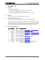
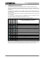
USE OF ST900 & ST750 FIRMWARE AND
HARDWARE CONFIGURATIONS
Siemens Plc
Mobility Division
Traffic Solutions
Sopers Lane
Poole, Dorset
BH17 7ER
United Kingdom
+44 (0)1202 782000
http://www.siemens.co.uk/traffic
SYSTEM/PROJECT/PRODUCT: ST900 and ST750 Families of Controller
USE OF ST900 AND ST750
FIRMWARE AND HARDWARE
CONFIGURATIONS
THIS DOCUMENT IS ELECTRONICALLY HELD AND APPROVED
Approved By: Dave Martin
Function: Engineering Manager
Issue
12
Change Ref
TS006625
Date
July 2012
© Siemens plc. 2012 All rights reserved.
The information contained herein is the property of Siemens plc and is supplied without liability for
errors or omissions. No part may be reproduced or used except as authorised by contract or other
written permission. The copyright and the foregoing restriction on reproduction and use extend to all
media in which the information may be embodied.
667/SU/32900/000
Page 1 of 23
Issue 12
USE OF ST900 & ST750 FIRMWARE AND
HARDWARE CONFIGURATIONS
CONTENTS
1 INTRODUCTION ................................................................................................................................. 3
1.1 Purpose .................................................................................................................................... 3
1.2 Scope ....................................................................................................................................... 3
1.3 Glossary ................................................................................................................................... 3
1.4 Document Issue History ........................................................................................................... 3
2 FIRMWARE DESCRIPTIONS ............................................................................................................. 4
2.1 PB801 ISSUE 1: 2007 Apr, LV Trial Only ................................................................................ 5
2.2 PB801 ISSUE 2: 2007 Jun, ELV Trial Only.............................................................................. 5
2.3 PB801 ISSUE 3: 2007 Jul, LV Trial Only ................................................................................. 5
2.4 PB801 ISSUE 4: 2007 Aug, Development Use Only ............................................................... 5
2.5 PB801 ISSUE 5: 2007 Sep, First Production Release............................................................. 6
2.6 PB801 ISSUE 6: 2008 Feb, Various Fault Fixes...................................................................... 6
2.7 PB801 ISSUE 7: 2008 Dec, ST750 and ST750ELV ................................................................ 6
2.8 PB801 ISSUE 8: 2009 Mar, LED Lamp Switch / LV CLS Retrofit............................................ 7
2.9 PB801 ISSUE 9: 2009 Nov, Wig-Wag ..................................................................................... 8
2.10 PB801 ISSUE 10: 2010 May, special conditioning fix.............................................................. 9
2.11 PB801 ISSUE 11: 2010 Sep, ST750LED................................................................................. 9
2.12 PB801 ISSUE 12: 2011 Sep, Conditioning Timers Increased ................................................. 9
2.13 PB801 ISSUE 13: 2012 Jul, Low-Power Near-Side KLT Profile............................................ 10
3 HARDWARE DESCRIPTIONS ......................................................................................................... 11
3.1 ST900/ST900ELV/ST750ELV ................................................................................................ 11
3.2 ST750 ..................................................................................................................................... 13
4 Compatibility .................................................................................................................................... 14
4.1 Differences between ST800 and ST900 ................................................................................ 14
4.2 Differences between ST700 and ST750 ................................................................................ 14
4.3 General Differences between PB800 and PB801.................................................................. 14
4.4 Phase Bus Processor (PHS) .................................................................................................. 15
4.5 Phase Bus Processor (PHP) .................................................................................................. 15
4.6 PLD Dongles .......................................................................................................................... 16
4.7 LSLS Cards (ELV Lamp Switch Cards) ................................................................................. 16
4.8 ELV LED Signals .................................................................................................................... 16
4.9 LV CLS LED Signals .............................................................................................................. 17
4.10 GPS Clock Facility.................................................................................................................. 17
4.11 Manual Panel and Extended System Bus.............................................................................. 18
4.12 Serial I/O Cards & Intelligent Detector Backplanes ............................................................... 18
4.13 Integral TC12 OTU ................................................................................................................. 18
4.14 Transport for London TfL IMU / IRM ...................................................................................... 19
4.15 3U-OMU and Gemini Unit ...................................................................................................... 19
4.16 5U OMU.................................................................................................................................. 20
5 Known Problems and Concessions .............................................................................................. 21
5.1 ST700/ST750 Platform........................................................................................................... 21
5.2 60Hz Mains [ref 0003284] ...................................................................................................... 21
5.3 Self-Test and OMU’s [ref 0003421]........................................................................................ 21
5.4 Self-Test and First Power-Up [ref 0003426]........................................................................... 21
5.5 Lamp Switch Cards (Mains LSC) ........................................................................................... 21
5.6 Unstable Current Readings from LSLS Cards [ref ECB08-0110] .......................................... 21
5.7 Early Problems with SDE/SA [ref 0003606 & 0003628] ........................................................ 22
5.8 Input States Are Forced Briefly On Start-Up [ref 0004040].................................................... 22
5.9 Erroneous DFM faults when controller shuts down [ref 0005974] ......................................... 22
5.10 Checksum Error during IC4 Config Download [ref 0004494]................................................. 22
5.11 Change in operation of Special Conditioning Timers [STAB10-0060] ................................... 23
5.12 Spurious LED Lamp Faults and the ‘KDP:2’ setting [ECB10-0125]....................................... 23
5.13 Controller stuck in start-up stage after firmware update [ECB11-0133] ................................ 23
667/SU/32900/000
Page 2 of 23
Issue 12
USE OF ST900 & ST750 FIRMWARE AND
HARDWARE CONFIGURATIONS
1
INTRODUCTION
1.1
Purpose
The purpose of this document is:1) To define the compatibility between all issues of Controller firmware
2) To define the compatibility between all hardware issues
3) To define the compatibility between the controllers and other traffic products
1.2
Scope
All issues of ST900 and ST750 Controller firmware and hardware
1.3
Glossary and Common Terms
Refer to the Glossary in the ST900 Family General Handbook 667/HB/32900/000.
The firmware part number “667/1/12801/000” is equivalent to the short part number “PB801”.
Reference numbers in the form ‘TS00####’ refer to change request documents (RFC) within
the Siemens Poole change control system. Reference numbers in the form ‘Ref 00#####’
refer to fault and enhancement reports within the Siemens Poole ‘bug tracker’ system.
1.4
Document Issue History
Issu
e
Change Ref
2
TS004349
Feb 2008 Added details of PB801 issue 6 and I/O Firmware issue 2
3
TS004453
Apr 2008 Added details of LSLS Firmware issue 5
4
TS004929
Feb 2009 Added details of PB801 issue 7 and LSLS Firmware issue 6
5
TS005084
Jul 2009 Added details of PB801 issue 8 and LSLS Firmware issue 7
6
TS005156
Jul 2009 Added AGD Near Side part no’s to section 4.8.
7
TS005217
Nov 2009 Added details of PB801 issue 9
8
TS005210
Feb 2010 Update for Gemini Lamp Supply Monitor
9
TS005476
Jun 2010 Added details of PB801 issue 10
10
TS005637
Sep 2010 Added details of PB801 issue 11
11
TS006244
Sep 2011 Added details of PB801 issue 12
12
TS006625
667/SU/32900/000
Date
Summary of Changes
Jul 2012 Added details of PB801 issue 13 and added additional
information to section 1.3 (Ref 0013953).
Page 3 of 23
Issue 12
USE OF ST900 & ST750 FIRMWARE AND
HARDWARE CONFIGURATIONS
2
FIRMWARE DESCRIPTIONS
The following sub-sections detail the changes made in each release of PB801 firmware.
Changes to the firmware for the Phase Bus Processor, LSLS Cards and I/O Cards since their
first formal release are recorded in the relevant subsections of section 4 referred to in the
table below.
This firmware (from PB801 issue 5 onwards) supports both the ST900 [Mains] Traffic
Controller and the ST900 ELV Traffic Controller; the same ST900 CPU Card is used in both
types of controller.
The firmware (from PB801 issue 7 onwards) also supports both the ST750 and ST750ELV
Traffic Controllers.
For a summary of changes between the ST800/ST700 family of controllers and the
ST900/ST750 families of Controllers, refer to sections 4.1 to 4.3.
Below is a summary of firmware issues for all parts of the Traffic Controller:
PIC /12801/
(IC4)
SIC /12815/
PHS /32931/
VLS /32941/
VIO /32998/
ST900, ST900ELV, ST750ELV
5
10
4
3
3
1 First Formal Release of the ST900 and ST900ELV
Ð
Ð
Ð
Ð
Ð
[4.12]
2 Fixes a problem with SDE/SA
Ð
Ð
Ð
Ð
4
Ð
Changes relating to the German hardware variant only [4.7]
6
Ð
Ð
Ð
Ð
Ð
Fixes various problems [2.6]
Ð
Ð
Ð
Ð
5
Ð
Fixes problem with stability of measurements [4.7]
Ð
Ð
Ð
Ð
6
Ð
7
11
Ð
Ð
Ð
Ð
Changes to allow 16-output LSLS Card for ST750ELV [4.7]
Support the ST750ELV Controller [2.7]
Ð
Ð
Ð
Ð
7
Ð
Changes relating to the German hardware variant only [4.7]
8
Ð
Ð
Ð
Ð
Ð
9
Ð
Ð
Ð
Ð
Ð
Adds support for Wig-Wags and fixes various problems [2.9]
10
Ð
Ð
Ð
Ð
Ð
Fixes the problem which occurred in Issue 9 [2.10]
11
Ð
Ð
Ð
Ð
Ð
Fixes various problems [2.11]
12
Ð
Ð
Ð
Ð
Ð
Various fixes and enhancements [2.12]
13
Ð
Ð
Ð
Ð
Ð
Adds low-power near-side profile [2.13]
[SEE OVER THE PAGE FOR THE ST750]
Comment
Adds support for Helios CLS without LMF and AGD near-sides
[2.8]
Note: ‘PIC’, ‘SIC’, etc., are handset commands showing the firmware versions of the main processor, the secondary
processor, etc.; refer to the Handset Handbook for details. The five digit number shown is the identifying number for
the firmware within the full part number 667/1/12nnn/000 (for a PROM; short form ‘PBnnn’) or 667/TZ/nnnnn/000
(otherwise). The IC4 software version is included for information only; refer to its document for full details.
667/SU/32900/000
Page 4 of 23
Issue 12
(IC4)
ST750
PIC /12801/
SIC /12817/
USE OF ST900 & ST750 FIRMWARE AND
HARDWARE CONFIGURATIONS
7
11
Ð
Ð
[2.7]
- Support the ST750 Controller
[4.5]
5 First to support the ST750 (Note: This is PB817 firmware, not PB815)
8
Ð
Ð
Fixes various problems [2.8]
9
Ð
Ð
Fixes various problems [2.9]
10
Ð
Ð
Fixes the problem which occurred in Issue 9 [2.10]
11
Ð
Ð
Adds support for the ST750LED Controller and fixes various problems [2.11]
12
Ð
Ð
Various fixes and enhancements [2.12]
13
Ð
Ð
No functional change [2.13]
Comment
The following lists the versions of ST900 main processor firmware used in its trial…
2.1
PB801 ISSUE 1: 2007 Apr, LV Trial Only
Produced to start the ST900 Mains Controller Trial but was not released into production.
2.2
PB801 ISSUE 2: 2007 Jun, ELV Trial Only
Produced to start the ST900 ELV Controller Trial but was not released into production.
2.3
PB801 ISSUE 3: 2007 Jul, LV Trial Only
Produced to upgrade the ST900 LV Trial Controllers but was not released into production.
2.4
PB801 ISSUE 4: 2007 Aug, Development Use Only
Produced as the first common build for both ST900 LV and ELV Controllers but was not
released into production.
667/SU/32900/000
Page 5 of 23
Issue 12
USE OF ST900 & ST750 FIRMWARE AND
HARDWARE CONFIGURATIONS
2.5
PB801 ISSUE 5: 2007 Sep, First Production Release
This was the first production release.
2.6
PB801 ISSUE 6: 2008 Feb, Various Fault Fixes
This release was produced to fix a number of problems found in both ST900 LV and ELV
Controllers. It differs from the previous firmware issue in the following ways:
2.7
•
Improved the ELV LED Near-Side lamp monitoring profile so it can also support STC
Toucan signals (ref 0003377).
•
Fixed: DFM faults sent to RMS Instation for all unconfigured I/O Ports (ref 0003501).
•
Fixed: Switched Signs only illuminate on an ELV Controller if a dummy phase is
configured in the same ‘position’ (ref 0003609).
•
Fixed: Occasionally SDE/SA extensions would be triggered on all phases with SDE/SA
even though no high speed vehicles had been detected (ref 0003628).
•
Improved the Self-Test so it displays the firmware issue of I/O cards (ref 0003627).
•
Fixed: Production Self-Test occasionally failed reporting “PHS fault code 4” (ref
0003426).
•
Allow the Level-3 pushbutton to be pressed after the SelfTest message “All LED Signals
to be covered before continuing...” in case an OMU is connected to the handset port (ref
0003421).
•
New lamp monitor diagnostic facility added; see handset commands KTE & KTR (ref
0003629).
PB801 ISSUE 7: 2008 Dec, ST750 and ST750ELV
This release was produced to support the new ST750 and ST750ELV Controllers. It differs
from the previous firmware issue in the following ways:
•
This release is the first to support the ST700/ST750 Controller. An ST700 can be
upgraded to an ST750 by replacing the CPU Card (to increase the RAM available and
change the firmware to the latest PB801 and PB817 versions). Refer to the ST750
General Handbook for full details.
•
This release is the first to fully support the ST750ELV Controller.
•
This release insists that the Phase Bus Processor firmware that performs green/amber
conflict checking is fitted; see section 4.5 for details (ref 0004102).
•
Fixed: PHP Phase Bus Processor firmware version not displayed during ST900ELV
SelfTest (ref 0004144)
•
Emulator – Simulated Lamp Loads (SLL) for ELV LED Signals now defaults a load
equivalent to four signals based on the expected number of watts per signal, rather than
a default of 10W per signal, since a 10W drop may not be enough to simulate a lamp
fault. On ELV Controllers, the SLL handset command now shows the number of lamps
simulated (SLL A R:4.0). On LV Controllers, the number of watts is still displayed (SLL A
R:200W) (ref 0003675 & 0004165).
667/SU/32900/000
Page 6 of 23
Issue 12
USE OF ST900 & ST750 FIRMWARE AND
HARDWARE CONFIGURATIONS
2.8
PB801 ISSUE 8: 2009 Mar, LED Lamp Switch / LV CLS Retrofit
This release was produced to support monitoring of CLS LED Signals on the ST900 LV
Controller, fix a number of problems found with the processing of digital inputs and various
other enhancements.
•
This release is the first to support monitoring of Helios CLS LED Signals without LMF
units using the new “LED Lamp Switch” PCB on the ST900 LV Controller; refer to the LV
CLS Handbook 667/HB/32921/007. (See PB801 issue 11 for the ST750 LV Controller)
•
Corrections to various digital input related facilities:
•
Additional demands inserted on power-up (ref 0004040)
•
DFA forcing of inputs when an I/O Card fails ignores IPS inversion (ref 0004039)
•
De-allocated inputs (IOA x=255) appear active if inverted (ref 0004103)
•
Problems with U/D inputs moved by IOA (ref 0002048)
•
Default U/D timeout (UDT) increased from 10 secs to 5 mins (ref 0004998)
•
The supply voltage reading can now be calibrated, see ‘KEV’ command (ref 0004850).
•
The mimic LEDs on LSLS Cards can be extinguished, see ‘LED’ command (ref 0002949).
•
New fault “FLF 61:255 TKE!” set if initialisation does not occur (ref 0004470).
•
This release includes the lamp monitoring profile for AGD LED Near-Side and Demand
Indicators on ST750ELV and ST900ELV Controllers (see section 4.8).
667/SU/32900/000
Page 7 of 23
Issue 12
USE OF ST900 & ST750 FIRMWARE AND
HARDWARE CONFIGURATIONS
2.9
PB801 ISSUE 9: 2009 Nov, Wig-Wag
This release was produced to provide a Wig-Wag controller and fix a number of minor
problems. It differs from the previous firmware issue in the following ways:
• This release is the first to support Wig-Wag Signals to TR2513A on ST900LED and
ST900ELV Controllers. Such controllers need special consideration and must only be
created by Intersection Engineering at Siemens, Poole.
• Corrections to the lamp monitor:
• Fixed: On an ELV Controller, a spurious lamp fault may be logged against the aspect
(colour) of a sensor that is not actually monitoring any load, e.g. WtOff. The problem
starts when the other aspects (e.g. Wait) illuminate, and one reading taken during their
in-rush is processed against the aspect that has no load (WtOff). This one spurious
reading can cause the (WtOff) learnt load to increase, under some circumstances. The
next time that aspect is monitored, the controller confirms the load is back to 0W, and
the spurious lamp fault is logged (against WtOff). The problem has also been seen on
other sensor types, e.g. ones that monitor red and green, but only green signals are
fitted (ref 0007311).
• Corrections to various digital I/O and demand related facilities:
• DFM faults could be logged erroneously after shutdown (ref 0005974)
• DFM stuck active faults could be logged as having changed on power-up (ref 0006761)
• UTC Reply Bit ‘CYC’ was active for longer than the required 3 seconds (ref 0004509)
• A request from a digital input for part-time mode on power-up may not be detected in
time to stop the start-up sequence (ref 0006935)
• Significant changes in operation:
• Improvement: Optional phases without a configured start-up demand no longer move to
ROW during the start-up sequence. If this change causes problems (see section 5.13),
use PMV=8 to disable this new functionality so all phases in the start-up stage move to
ROW, as on previous versions of firmware (ref 0003981).
• Improvement: If the only demands present are for phases in the current stage but the
phases are at no ROW (e.g. Type 1 peds) the arterial or next stage is automatically
demanded so these demands can be serviced. This used to require Special
Conditioning. Use PMV=16 to disable this new firmware feature (ref 0006843).
• Improvement: Special Conditioning: When a timer is started by the RUN operator, the
states of the conditioning mnemonics CNDTMA and CNDTER are updated
immediately, not 200mS later. This means that a timer started with 0.2 seconds now
sets CNDTMA (ref 0005942). However this improvement can cause problems (see
Mantis #0009101, RFC 5476 & STAB10-0060) and is therefore disabled by default in
PB801 issue 10.
• Improvement: Flashing is now synchronised with the signal sequence so the first flash
of any signals is the correct duration (ref 0006480)
• Other changes:
• Additional checksum check added to the Phase Bus Processor’s config data (ref
0003006)
• Siemens / Futurit Helios LV CLS thresholds improved in load type KLT s:10 (ref
0005666)
• Handset Mnemonic KES: Rather than displaying ‘0mA’, the display clearly identifies
when no reading has been taken or the reading has been forced to zero (ref 0004929);
see 667/HH/32900/000 for details (issue 6 or later).
667/SU/32900/000
Page 8 of 23
Issue 12
USE OF ST900 & ST750 FIRMWARE AND
HARDWARE CONFIGURATIONS
2.10
PB801 ISSUE 10: 2010 May, special conditioning fix
This release was produced solely to correct a problem with PB801 issue 9. It differs from the
previous firmware issue in the following ways:
• The improvement to Special Conditioning Timers in PB801 issue 9 (ref 0005942) has been
found to cause problems with existing Special Conditioning. In issue 10, this change has
been reversed so that, by default, timers operate in the original fashion (ref 0009101).
2.11
PB801 ISSUE 11: 2010 Sep, ST750LED
This release was produced to support monitoring of LV CLS LED Signals on the ST750
Controller and fix a number of minor problems. It differs from the previous firmware issue in
the following ways:
• This release is the first to support the ST750LED Controller, the ‘LV CLS Retrofit’ facility on
the ST750 platform. See section 3.2 starting on page 13 and the LV CLS Handbook
667/HB/32921/007 issue 6 or later for more information.
• The problem with the ‘KDP:2’ setting and LED Signals has been fixed (ref 0008551). See
section 5.12 on page 23 for details.
• Corrections to various handset commands:
• KTR improved to show the day of week and an asterisk to mark the most recent
record (ref 0009571)
• KES displays “[RLM:0]” on those sensors configured to monitor the second stream of
a single stream ped controller (ref 0009790)
• KES and KTR correctly display the supply voltage of 48V sensors on the ST750
controller (ref 0009791 & 0009800)
• The interaction between the KLT and RLM commands has been improved; if a
sensor is disabled by KLT s=0, the number of RLM channels shown by the RLM
command is reduced (ref 0009792).
• Adds the Siemens Silux LED Profile (KLV:7/8 and KLT s:11)
• SelfTest now displays the type of serial I/O card next to the firmware version (ref 0009781):
IDB = Intelligent Detector Backplane
4o = Serial I/O Card: 24 inputs / 4 outputs
16o = Serial I/O Card: 24 inputs / 16 outputs
750 = ST750ELV combined PSU/IO module
2.12
PB801 ISSUE 12: 2011 Sep, Conditioning Timers Increased
This release was primarily produced to provide more Conditioning Timers and also improve
the GPS Clock synchronisation algorithm. It differs from the previous firmware issue in the
following ways:
•
The number of Conditioning Timers available has been increased from 96 to 480 (ref
0009219).
•
New Special Conditioning operators have been added to hold, resume and wipe a
Conditioning Timer (ref 0012367).
•
Added 1024 general purpose ‘Conditioning Facility Flags’ – to allow the most flexibility, both
Special Conditioning and the new handset command “CFF” (which is access level 2) have
read and modify the state of each flag (ref 0009129 & 0009649).
•
The GPS Clock Synchronisation algorithm has been improved so that it will work with halfhour time zones – such as ‘India Standard Time’ (GMT+5.5) is 5 hours 30 minutes ahead of
Greenwich Mean Time (ref 0012400).
667/SU/32900/000
Page 9 of 23
Issue 12
USE OF ST900 & ST750 FIRMWARE AND
HARDWARE CONFIGURATIONS
2.13
PB801 ISSUE 13: 2012 Jul, Low-Power Near-Side KLT Profile
This release was produced to add a KLT profile (see section 4.8) for the new low-power nearside pedestrian signals from Siemens.
667/SU/32900/000
Page 10 of 23
Issue 12
USE OF ST900 & ST750 FIRMWARE AND
HARDWARE CONFIGURATIONS
3
HARDWARE DESCRIPTIONS
Note: The ST900 and ST750 family of controllers re-use several of the expansion PCBs from
the ST800, with details in the indicated part of section 4. For information on the changes for
each issue of the following PCBs refer to the ST800 Compatibility document
667/SU/27000/000. The ST900 and ST750 families of controllers are compatible with all
issues of these PCBs.
3.1
•
[4.11] – Expansion I/O PCB – 667/1/20229/001 [option on ST750 only]
•
[4.11] – SDE/SA PCB – 667/1/20231/000 [option on ST900 and ST900ELV only]
•
[4.13] – Integral OTU (Ancillary Processor) – 667/1/21611/001
•
[4.14] – Integral London IMU/IRM – 667/1/25169/001
ST900/ST900ELV/ST750ELV
3.1.1 Main Processor Card – 667/1/27023/xxx
•
Variant /003 (ST900 Switch Processor- No on-board IO)
Issue 01: Released
Issue 02: Minor BOM changes
Issue 03: Remove Back-EMF suppression diodes V51, V52, V53
Issue 04: Updated BOM to include PROM Kit
Issue 05: Update to PCB to help manufacture
Issue 06: RAM part change
Issue 07: Updated BOM to help manufacture
Issue 08: Update to PCB - EMC
3.1.2 PHS Card – 667/1/32934/xxx
•
Variant /001
Issue 01: Released
Issue 02: Add w/dog inhibit link
Issue 03: W/dog link moved to component side of board
3.1.3 Mains LSC – 667/1/27221/xxx, 667/1/27223/xxx, 667/1/33905/xxx
Commonly used variants:
• /002 – (Original) Non-UK Variant (with Fail to Flashing option)
• /012 – (Original) UK Variant (Fail to Blackout)
• /302 – “LED Lamp Switch” – Non-UK Variant (with Fail to Flashing option)
• /312 – “LED Lamp Switch” – UK Variant (Fail to Blackout)
The ST900 controller is compatible with all variants and issues of these PCBs, except:
• The ST900 is not compatible with the variant used in the ST800P (667/1/27223/402).
This is because there is no equivalent ST900P; the ST750 and ST750ELV are the small
stand-alone pedestrian controllers in this family.
• “LED Lamp Switch” (667/1/33905/3xx) – refer to Section 4.9 for firmware compatibility
and the LV CLS Handbook 667/HB/32921/007 for more information.
For details on the various issues of these cards, refer to the ST800 Compatibility document
667/SU/27000/000.
667/SU/32900/000
Page 11 of 23
Issue 12
USE OF ST900 & ST750 FIRMWARE AND
HARDWARE CONFIGURATIONS
3.1.4 ELV LSLS Card – 667/1/32943/xxx
•
Variant /001 (For UK – 32 Output LSLS Card)
Issue 01: Released
Issue 02-11: Minor changes
Issue 12: Minor part changes (ref TS005075)
•
Variant /002 (German Controller only)
The controller is NOT compatible with this variant of the PCB.
•
Variant /003 (For UK – 16 Output LSLS Card)
Issue 01: Released
Issue 02: Minor part changes (ref TS005075)
3.1.5 Serial IO Card – 667/1/32990/xxx
•
Variant /001 (24 in / 16 out)
Issue 01: Released
Issue 02: Minor changes
Issue 03: Add w/dog inhibit link
Issue 04: BOM change to fit screw-retained Phoenix connectors
•
Variant /002 (24 in / 4 out)
Issue 01: Released
Issue 02: Minor changes
Issue 03: Add w/dog inhibit link
Issue 04: BOM change to fit screw-retained Phoenix connectors
3.1.6 Backplane Controller – 667/1/32913/xxx
•
Variant /001 (Parallel Comms to Loop Cards)
Issue 01: Released
Issue 02: Add w/dog inhibit link
3.1.7 Mains Distribution PCB ST900 MDU – 667/1/27025/xxx
•
Variant /000 (Standard)
The ST900 is compatible with all issues.
•
Variant /001 (May be used in an ST900SE)
The ST900 is compatible with all issues.
3.1.8 Mains Distribution PCB ST900ELV LPU – 667/1/32971/xxx
•
Variant /001
Issue 01: Released
3.1.9 ST750ELV I/O-PSU PCB – 667/132971/xxx
•
Variant /000
Issue 01: Released
667/SU/32900/000
Page 12 of 23
Issue 12
USE OF ST900 & ST750 FIRMWARE AND
HARDWARE CONFIGURATIONS
3.2
ST750
3.2.1 ST750 Main Processor Card – 667/1/27831/xxx
•
Variant /001 (ST700 stand-alone pedestrian)
Replace with /003 for ST750.
•
Variant /003 (ST750 stand-alone pedestrian)
Issue 01: Released
•
Variant /006 (ST700 export intersection)
Replace with /007 for ST750.
•
Variant /007 (ST750 export intersection)
Issue 01: Released
3.2.2 ST700/ST750 Phase Driver Card – 667/1/27833/xxx
•
The ST750 is compatible with all variants and issues of the ST700 Phase Driver Card.
3.2.3 ST700/ST750 LED Phase Driver Card – 667/1/33790/xxx
•
The firmware needs to be PB801 issue 11 or later to support the ST750 LED Phase
Driver Card. See the handbook 667/HB/32921/007 issue 6 or later for more details on the
ST750LED Controller.
667/SU/32900/000
Page 13 of 23
Issue 12
USE OF ST900 & ST750 FIRMWARE AND
HARDWARE CONFIGURATIONS
4 COMPATIBILITY
4.1
Differences between ST800 and ST900
The first formal release of the ST900 Controller (firmware PB801 issue 5) differs from the
ST800 Controller (firmware PB800 issue 24) in the following ways:
4.2
•
ELV – The ST900 ELV Controller uses new LSLS lamp switch cards and associated
power distribution parts to drive and monitor ELV LED Signals.
•
IO – The ST900 and ST900ELV support new Serial I/O Cards and Intelligent Detector
Backplanes. They no longer supports the ST800 Expansion I/O Cards on the
Extended System Bus, nor do they support the 16 inputs and 4 outputs on the CPU
Card (indeed there is no I/O fitted on the ST900 CPU Card).
•
SDE – Integral SDE/SA should now be used by default through the new Serial I/O
Cards and Backplanes. It no longer requires the /102 PLD. The SDE/SA Card on the
Extended System Bus is still supported by the firmware.
•
Also see section 4.3 below.
Differences between ST700 and ST750
The first release of the ST750 Controller (firmware PB801 issue 7) differs from the ST700
Controller (firmware PB800 issue 24) in the following ways:
4.3
•
CPU – The ST700 and ST750 CPU Cards look very similar. However, the ST750
requires at least 512KB of RAM; only 256KB is fitted to most ST700 CPU Cards
(3.2.1).
•
PHP – PB801 and the ST750 require PB817 issue 5 or later; PB800 and the ST700
can use PB817 issue 3 or later (which includes PB817 issue 5).
•
IO – PB801 firmware on the ST700/ST750-style controller continues to use the I/O
built in to the CPU Card, with the option of adding one Expansion I/O Board.
•
SDE – Integral SDE/SA is still used, using the I/O on the CPU Card. The SDE/SA
Card on the Extended System Bus is not supported by the firmware.
•
Config – The standard stand-alone pedestrian configurations have changed. A list of
these can be found in the IC4 ReadMe file (v11) and the ST750 General Handbook.
A list of the significant changes between a new ST750 standard configuration and its
original ST700 configuration is included in its Special Instructions (from issue 2).
•
Also see section 4.3 below.
General Differences between PB800 and PB801
The first release of PB801 firmware (issue 5) differs from PB800 firmware (issue 24) in the
following ways:
•
IO – The maximum number of I/O Ports supported by the firmware has been
increased from 12 to 31, increasing the number of I/O Lines from 96 to 248.
•
Kerbsides – As required by TR2500A in the UK, pushbuttons now insert a latched
demand if they are pressed while their associated kerbside detector is inactive. If its
associated kerbside detector is active, an unlatched demand is inserted (which is
cancelled when all the kerbside detectors for the phase go inactive).
IMPORTANT: This means that where kerbsides are used, care must be taken to ensure that the
pushbuttons and kerbsides detectors are wired to the correct inputs. Each pushbutton device and kerbside
detector must be wired to its own dedicated input. For each pushbutton input, the IC4 configuration assigns
an associated kerbside input, to which must be connected the kerbside detector covering the pavement
area around that specific pushbutton device.
667/SU/32900/000
Page 14 of 23
Issue 12
USE OF ST900 & ST750 FIRMWARE AND
HARDWARE CONFIGURATIONS
4.4
•
DFM – DFM Faults on the individual I/O lines no longer appear in the Fault Log Data
(FLD) and should be interrogated using the DSF handset command, which also
displays the I/O Line Number and IC4 Name as well as indicating whether the input
failed active (1) or inactive (0).
•
DFM – The ‘Reset DFM’ facility (RDF=1 for example) will now clear the DFM fault flag
(FLF12) and extinguish the System Error LED.
•
Priority – The ‘Automatic Reset’ option of the Priority DFM Facility (PDR) has been
improved so that a number of activations can be specified; the N’th activation is
allowed and the fault is automatically cleared.
•
Handset – The handset now auto-detects Eight Data Bits with No Parity Bit (8N) as
well as continuing to support Seven Data Bits with an Even Parity Bit (7E) and 1200,
9600 and 19200 bps.
•
Handset – Level 2 (PME) and Level 3 (Pushbutton) Access Timeout Periods are
restarted if Level 2 or 3 data is changed (including RFL=1 for example) or the PME
access code is re-entered.
•
Config – The new CID handset command displays the firmware version (as entered
on the IC4 Admin Screen) ‘desired’ by the configuration currently running a controller.
The EM number and issue of the configuration is still visible using the CIC handset
command.
•
Config – The version of firmware required by a new configuration is checked before
the existing configuration is erased. An “FLF 21:255 CPAT” fault logged if the new
configuration requires a later version of firmware. The version required by the
configuration which failed to load can be seen using the new CIE handset command.
Phase Bus Processor (PHS)
PB801 firmware is compatible with the ‘Serial’ PHS Phase Bus Processor firmware
667/TZ/32931/000 issue 3 onwards.
There are no known hardware compatibility problems with the PHS Cards.
Note: The PHS is not used on an ST750.
4.5
Phase Bus Processor (PHP)
IMPORTANT: From PB801 issue 7 onwards, the main processor firmware includes checks to
ensure the correct version of Phase Bus Processor firmware is fitted on an LV Controller in
order to ensure that both microprocessors are independently performing the green/amber
conflict check.
ST900 Controllers: These require PB815 issue 4 or later. From PB801 issue 7 onwards,
normal operation will not start up and instead will log the fault “FLF 2:253 PBUS” if
PB815 issue 2 is fitted. SelfTest will also shutdown and report the incompatibility.
ST900ELV and ST750ELV Controllers: Normal operation will permit PB815 issue 2 to be
used. However, from PB801 issue 7 onwards, SelfTest will shutdown and report the
incompatibility as above.
ST750 Controllers: These controllers use the ST700/ST750 CPU Card and not the ST900
CPU Card and so use PB817 Phase Bus Processor firmware rather than PB815. The
controller will insist that PB817 issue 5 (or later) is fitted.
Legacy information:
ST800 controllers can use PB815 issue 2 or PB815 issue 4 (no functional difference).
ST700 controllers can use PB817 issue 3 or PB817 issue 5 (no functional difference).
667/SU/32900/000
Page 15 of 23
Issue 12
USE OF ST900 & ST750 FIRMWARE AND
HARDWARE CONFIGURATIONS
4.6
PLD Dongles
ST900, ST900ELV and ST750ELV Controllers: Only the original and default /000 variant of
ST800 PLD 667/1/12821/000 is required. The /102 variant of PLD is not needed; Integral
SDE/SA is available on these controllers with the standard /000 variant. The /121 and /122
PLDs developed for the ST800P are not currently used.
ST750 Controllers: These controllers use either the /122 (Pedestrian) or /102 (Non-UK)
variants of PLDs. These devices are the same as those used on the ST700.
4.7
LSLS Cards (ELV Lamp Switch Cards)
PB801 firmware is compatible with LSLS firmware 667/TZ/32941/000 issue 3 onwards.
667/TZ/32941/000 issue 4 includes a number of changes to assist in production testing and
for the German hardware variant of the LSLS Card It can be used in the UK variant of the
LSLS Card and does not affect the operation.
667/TZ/32941/000 issue 5 fixes a problem with the stability of measurements which can
cause lamp faults to be reported erroneously. IMPORTANT: LSLS Cards with firmware issue
4 or earlier must be replaced with cards with firmware issue 5 or later (ref ECB08-0110).
667/TZ/32941/000 issue 6 is the first to support a 16-channel LSLS Card (for ST750ELV).
667/TZ/32941/000 issue 7 includes a change for the German hardware variant of the LSLS
Card (ref 0005366). It can be used in the UK variant of the LSLS Card and does not affect the
operation.
There are no known hardware compatibility problems with the LSLS Cards.
4.8
ELV LED Signals
The ST750ELV and ST900ELV Controllers have been tested with the following ELV LED
Signals:
•
[KLT:1] STC Helios ELV Signals [NEW]
(Used for both Vehicle Signals and Far-Side Pedestrian and Bicycle Signals)
•
[KLT:2] STC Pedestrian Demand Accepted Indicators [MODIFIED]
o 667/1/30680/001 Issue 3 and above.
•
[KLT:3] STC Near-Side Red / Green Man and Toucan LED Signals [MODIFIED]
o 667/1/30695/001 Issue 9 and above – Green Puffin
o 667/1/30695/002 Issue 9 and above – Red Puffin
o 667/1/30695/003 Issue 9 and above – Green Toucan*
o 667/1/30695/004 Issue 10 and above – Red Toucan*
o 667/1/30695/005 Issue 9 and above – Green Equestrian*
o 667/1/30695/006 Issue 10 and above – Red Equestrian*
* PB801 issue 5 should not be used with STC Toucan and
Equestrian Near-Side LED Signals; use PB801 issue 6 or higher.
•
[KLT:4] STC ELV LED Regulatory Signs [NEW]
•
[KLT:5] STC LED Wait Indicators [MODIFIED]
o 667/1/30211/001 Issue 4 and above
From PB801 issue 8 onwards:
• [KLT:6] AGD Near-Side Red / Green Man and Toucan LED Signals [MODIFIED]
•
[KLT:7] AGD Pedestrian Demand Accepted Indicators [MODIFIED]
•
Compatible Signal Types:
o Puffin Signals: AGD940-660-000, AGD940-661-000,
667/SU/32900/000
Page 16 of 23
Issue 12
USE OF ST900 & ST750 FIRMWARE AND
HARDWARE CONFIGURATIONS
o
o
o
o
Demand Units: AGD941-660-000, AGD941-662-000, AGD941-663-000,
Toucan Signals: AGD942-660-000, AGD942-661-000,
Combined Puffin: AGD946-660-000, AGD946-662-000, AGD946-665-000,
AGD946-666-000,
Combined Toucan: AGD947-660-000, AGD947-662-000, AGD947-664-000,
AGD947-666-000
From PB801 issue 13 onwards:
• [KLT:8] Siemens Low-Power Puffin and Toucan Near-Side Signals
o PCBs with part numbers 667/xx/33655/xxx
No other types of ELV Signals should be connected to these controllers without first
consulting Siemens Poole. The current profiles of these signals may cause the Controller to
sporadically report erroneous lamp faults or fail to confirm a real lamp fault. They may also
trigger the over-current / short-circuit check (FLF 33:1) performed by the controller,
particularly when the signal is first switched on.
The near-side pedestrian signals (including Wait and Demand Accepted Indicators) have
been modified to function with the ST900 and ST750 ELV Controller and are clearly marked
“ELV”. Unmodified original signals may cause similar problems to those described above.
Visual identification of the compatible Siemens assemblies is described within the “Appendix
– Visual Identification of ELV PCB. Assemblies” in the Helios General Handbook
667/HB/30000/000 issue 14 onwards.
The text ‘[KLT:n]’ indicates the Load Type number ‘n’ that needs to be configured, either on
the IC4 configuration screens or by using the handset command KLT, in order to lamp
monitor each type of ELV LED Signal. See 667/HH/32900/000 for details on this command.
4.9
LV CLS LED Signals
The ST750LED and ST900LED Controllers have been tested with the following LV LED
Signals. These signals are used for both Vehicle Signals and Far-Side Pedestrian and
Bicycle Signals. These controllers are not capable of monitoring LED near-side pedestrian /
cycle signals.
From PB801 issue 8 onwards:
• [KLT:1] Siemens / Dialight
•
[KLT:10] Siemens / Futurit
From PB801 issue 11 onwards:
•
[KLT:11] Siemens SILUX 1.230d Traffic
The text ‘[KLT:n]’ indicates the Load Type number ‘n’ that needs to be configured, either on
the IC4 configuration screens or by using the handset command KLT, in order to lamp
monitor each type of LED Signal. See 667/HH/32900/000 for details on this command.
NOTE: The correct Lamp Switch Card must also be installed on these controllers for LV LED
Signals. The LSC should be a 667/1/33905/3xx variant and labelled "LED Lamp Switch" [3.1.3]
4.10
GPS Clock Facility
No known compatibility problems.
667/SU/32900/000
Page 17 of 23
Issue 12
USE OF ST900 & ST750 FIRMWARE AND
HARDWARE CONFIGURATIONS
4.11
Manual Panel and Extended System Bus
PB801 firmware is still compatible with the Manual Panels and the Extended System Bus
used by the T400 and ST800. However, PB801 firmware is not necessarily fully compatible
with all the cards that could be connected to the Extended System Bus:
• Integral OTU – Supported. Refer to section 4.13 for more information.
•
TfL IMU Card – Supported. Refer to section 4.14 for more information.
ST900 / ST900ELV / ST750ELV:
• Expansion I/O Cards – Not supported; Serial I/O Cards and Intelligent Detector
Backplanes are used instead. Refer to section 4.12 for more information.
•
SDE/SA Card – Is still supported, but is only needed if the customer insists on having
a SoundMark Test Interface. Integral SDE/SA should be used by default and this no
longer requires the /102 PLD.
ST750:
• Expansion I/O Cards – One is supported by an ST750 controller to increase the I/O
capability. Serial I/O Cards and Intelligent Detector Backplanes are not used on the
ST750.
•
4.12
SDE/SA Card – Is not supported. Integral SDE/SA should be used.
Serial I/O Cards & Intelligent Detector Backplanes
PB801 is compatible with Serial I/O Card and Detector Backplane firmware
667/TZ/32998/000 issue 1 onwards. Note that the same firmware is used in both the Serial
I/O Cards and the Intelligent Detector Backplanes.
667/TZ/32998/000 issue 2 (or later) must be used at sites using SDE/SA. If issue 1 is used,
the controller will insert permanent artificial SDE/SA extensions (as seen using the SEA
handset command).
Note: The ST750 Controller does not use these; see section 4.2 for details.
There are no known hardware compatibility problems with these cards.
Other traffic equipment will not be able to access and therefore monitor the states of the loop
detector card output relays when these are plugged in to the Controller’s Intelligent Detector
Backplanes. If it is required to monitor these detector outputs (inputs to the controller), then
the loop detector cards must be connected to individual loop detector backplanes and ‘softwired’ to the inputs on a Controller Serial I/O Card instead.
4.13
Integral TC12 OTU
PB801 is compatible with the Integral TC12 OTU with the following limitations.
•
Control and Reply only – For use with an integral OTU to give the facility for control
and reply the required software should be PB392 issue 6 or greater.
•
Upload / Download and Remote Handset – To facilitate these features via an Integral
OTU it is required that the firmware be PB392 issue 7 or greater and the PLD be
PB393 variant /104 or /105 issue 2 or greater.
•
Detector Inputs – The Integral TC12 OTU can only use detector inputs within the first
12 I/O Ports of the Controller. Thus any SCOOT Loop Detectors or other detector
inputs that the OTU needs to use must be configured within the first 12 I/O Ports of
Controller.
•
Lamp Monitoring – The lamp monitoring function available within this card is not
required and is therefore not supported; lamp monitoring is provided within the
controller.
667/SU/32900/000
Page 18 of 23
Issue 12
USE OF ST900 & ST750 FIRMWARE AND
HARDWARE CONFIGURATIONS
4.14
Transport for London TfL IMU / IRM
The Controller is compatible with the IMU card (PB581 firmware issue 5 onwards), although
we are aware of the following issues.
4.15
•
The IMU firmware will only allow the TfL Instation access (using upload / download
messages) to the data relating to first 96 I/O lines.
•
DFM faults on higher I/O lines are still logged in and reported by the IMU.
•
If the IMU obtains its logic (and modem) power from the Controller’s 24V DC supply
(using a 24V to 12V DC-DC Converter for example), this limits the maximum number
of Serial I/O Cards and Intelligent Detector Backplanes that can be fitted to the
Controller. See the ST900 General Handbook 667/HB/32900/000 for details.
3U-OMU and Gemini Unit
PB801 is compatible with the Gemini Unit with the following limitations.
For information on the hardware and firmware versions of Gemini that provide the various
facilities mentioned below, refer to the Gemini documentation, particularly its compatibility
document 667/SU/30600/000.
•
IO – The Siemens OMU is limited to 8 input ports (64 inputs). Thus only controller
inputs on its first 8 input ports (output ports are automatically skipped) can be ‘named’
and utilised in the OMU and RMS System (using a semi-integral unit). Also note that
the mapping of input and outputs ports is much more flexible on the ST900 than it
ever was on the ST800. Therefore, the mapping of Controller Input Ports to OMU
Input Ports will vary much more between different ST900 Controllers than it ever did
between different ST800 Controllers.
•
IO – A free-standing Gemini Unit will not be able to monitor the states of the loop
detector output relays when the detector cards are fitted in a Controller Intelligent
Detector Backplane. Refer to section 4.12 for more information.
•
DFM – DFM faults on later controller input ports are still logged and reported by the
OMU correctly, but these cannot be ‘named’ at the RMS Instation.
There was an issue with PB801 issue 5 in that it caused erroneous DFM fault reports
to be logged for unconfigured I/O lines. This was fixed in PB801 issue 6.
There was also a minor issue with the RMS Instation (ref CQv100007367) in that only
two digits of three digit I/O line numbers are displayed, e.g. “03” is displayed for I/O
line number 103. This was fixed in RMS issue 39.00
•
ELV – Lamp faults confirmed by the ST900 LV or ELV Controller are passed through
a Serial OMU and reported to the RMS Instation. The free-standing OMU is not able
to lamp monitor ELV LED Signals.
•
ELV – The Mains State Inputs of a free-standing OMU can not be used to monitor the
‘green states’ of ELV traffic signals; use the semi-integral ‘Serial’ OMU option.
•
ELV – on an ST900ELV Controller, the Serial OMU will report ‘Lamps Off’ to the RMS
Instation if the serial link to the controller fails or is unplugged. An ELV alternative to
connecting the controller’s 230V/160V lamp supply to a dedicated Mains State Input
on the OMU is available, see ELV Lamp Monitor Kit 667/1/32612/000 (details on
drawing 667/GA/32612/000). Use of this ELV Lamp Monitor Kit allows the
ST900ELV Controller to determine whether the lamp supply is present when the
serial link fails, and report to the Instation accordingly.
•
Serial Link – When it is required to send a configuration from IC4 to the Controller (or
retrieve a configuration or perform an ‘IC4 View Differences’), the computer must be
connected directly to the Controller’s handset port. The Serial Gemini Unit must be
temporarily disconnected.
•
Serial MOVA – No known limitations with the ST900. Serial MOVA can obtain its
detector inputs from any of the controller I/O ports; it is not limited to the first 96 I/O
lines.
667/SU/32900/000
Page 19 of 23
Issue 12
USE OF ST900 & ST750 FIRMWARE AND
HARDWARE CONFIGURATIONS
4.16
•
Reactive DUSC – No known limitations with the ST900.
•
Bus Processor – No known limitations with the ST900.
•
UTMC OTU – No known limitations with the ST900.
5U OMU
We cannot guarantee that the ST900 is compatible with the 5U OMU. We are aware of the
following issues:
•
The 5U OMU will not be able to monitor the states of the loop detectors connected to
the Controller’s Intelligent Backplanes since the relay outputs from the loop detector
cards are not available. See section 4.12 for more information.
•
The 5U OMU is unable to lamp monitor the ELV LED Signals used on the ST900
Controller.
667/SU/32900/000
Page 20 of 23
Issue 12
USE OF ST900 & ST750 FIRMWARE AND
HARDWARE CONFIGURATIONS
5 KNOWN PROBLEMS AND CONCESSIONS
5.1
ST700/ST750 Platform
PB801 firmware prior to issue 7 does not support the ST700/ST750 Platform and therefore
will immediately shutdown reporting the fault “ST700 NOT SUPPORTED” on the handset.
Fixed in PB801 issue 7, released December 2008.
For more details on the ST750 see section 4.2.
5.2
60Hz Mains [ref 0003284]
(ST900 ELV Only)
It is not possible to run the ST900 ELV Controller on 60Hz Mains with more than 4 LSLS
Cards. No work-around possible.
5.3
Self-Test and OMU’s [ref 0003421]
(ST900 and ST900 ELV)
If an OMU or similar device is connected to the Controller’s handset port when SelfTest is
started, SelfTest does not appear to start Part 2 when the Level-3 Pushbutton is pressed. The
OMU should be disconnected from the handset port.
This is because the Controller has detected a device connected to the handset port and so
has transmitted a warning (about LED Signals) and is waiting for the user to read the warning
on the screen and press ‘any key’ to continue. In this situation, the controller should have
accepted the Level-3 Pushbutton as ‘any key’ but does not.
Fixed in PB801 issue 6, released February 2008.
5.4
Self-Test and First Power-Up [ref 0003426]
(ST900 ELV Only)
If a ‘virgin’ CPU Card is only ever started in to SelfTest mode, then it may shutdown reporting
‘PHS Fault Code 4’. Work-around; power-up the controller in to normal operation first (even if
no configuration PROM is present), then power OFF and ON to start SelfTest.
Fixed in PB801 issue 6, released February 2008.
5.5
Lamp Switch Cards (Mains LSC)
(ST900 Only)
Ensure that the 10A fuses FS1 and FS2 are Ceramic (518/4/97056/010) and not Glass
(518/4/97020/120).
5.6
Unstable Current Readings from LSLS Cards [ref ECB08-0110]
(ST900ELV / ST750ELV)
IMPORTANT: LSLS Cards with firmware issue 4 or earlier must be replaced with cards with
firmware issue 5 or later (ref Engineering Change Bulletin ECB08-0110). The handset
command ‘VLS’ and the Controller SelfTest show the version of LSLS firmware installed.
LSLS firmware issue 5 fixes a problem with the stability of measurements which can cause
lamp faults to be reported erroneously.
Fixed in 667/TZ/32941/000 issue 5, released April 2008.
667/SU/32900/000
Page 21 of 23
Issue 12
USE OF ST900 & ST750 FIRMWARE AND
HARDWARE CONFIGURATIONS
5.7
Early Problems with SDE/SA [ref 0003606 & 0003628]
(ST900 / ST900ELV)
At sites using SDE/SA, the Main Processor firmware (PIC) must be issue 6 or later and I/O
card firmware (VIO) must be issue 2 or later.
If PB801 issue 5 is used, occasionally SDE/SA extensions would be triggered on all phases
with SDE/SA even though no high speed vehicles had been detected (ref 0003628).
If an I/O card with issue 1 firmware is used, the controller will insert permanent artificial
SDE/SA extensions (as seen using the SEA handset command (ref 0003606).
Sites originally installed with these older versions of firmware have all been updated.
However, use caution and check the firmware issues if an old installation is modified to use
SDE/SA or an old spare PCB is used to upgrade/repair an installation with SDE/SA.
Fixed in PB801 issue 6 and 667/TZ/32998/000 issue 2, released February 2008.
5.8
Input States Are Forced Briefly On Start-Up [ref 0004040]
(ST750ELV / ST900 / ST900ELV)
Between powering up and the firmware detecting and configuring all the serial I/O cards (and
detector backplanes), the digital inputs are forced to their failure states, i.e. all open circuit
except those inverted or configured to go active on DFM failure (which are immediately forced
active). This can lead to undesirable demands being latched on power-up.
Fixed in PB801 issue 8, released March 2009.
5.9
Erroneous DFM faults when controller shuts down [ref 0005974]
(ST750ELV / ST900 / ST900ELV)
When the controller is shutdown (e.g. after a correspondence fault) all the inputs freeze
because serial I/O communications cease. However, nothing suspends Detector Fault
Monitoring so erroneous stuck active/inactive faults are logged if the controller remains
shutdown for some time.
Fixed in PB801 issue 9, released November 2009.
5.10
Checksum Error during IC4 Config Download [ref 0004494]
(ST750 Only)
If IC4 displays a message indicating that there is a checksum fault with the configuration just
downloaded to an ST750 Controller, it may be because the ST750 CPU Card is faulty, rather
than being a problem with the configuration file or the download process.
The memory checks performed by the ST750 firmware may not detect certain types of fault
with the additional RAM used only to temporarily store the configuration downloaded by IC4.
Therefore, it is possible that a fault with the RAM is present but is not detect by the controller
until a configuration download is attempted.
Work-around: If this error message is seen, try downloading the configuration a second time.
If the error message occurs again, replace the ST750 CPU Card and return the faulty card for
repair.
667/SU/32900/000
Page 22 of 23
Issue 12
USE OF ST900 & ST750 FIRMWARE AND
HARDWARE CONFIGURATIONS
5.11
Change in operation of Special Conditioning Timers [STAB10-0060]
(ST750 / ST750ELV / ST900 / ST900ELV)
In PB801 Issue 9 the implemented change in operation of the Special Conditioning Timers
had a detrimental effect on some of the controllers. This change in some instances would
stop Special Conditioning from working correctly (see Technical Bulletin STAB10-0060 for full
details).
The PB801 Issue 10 therefore, by default, reverted back to the original way of working and
disabled this change.
Fixed in PB801 Issue 10, released May 2009.
Additional Note: PB801 Issue 12 and IC4 version 11.4 add a new conditioning operator called
"RAN" that allows the configuring engineer to select the original "RUN" or improved "RAN"
operation of the timers.
5.12
Spurious LED Lamp Faults and the ‘KDP:2’ setting [ECB10-0125]
(ST750ELV / ST900LED / ST900ELV)
As required, the ‘KDP:2’ setting disables dim/bright monitoring. However, this has a
detrimental effect on the learning of LED lamp loads, which can lead to erroneous lamp faults
being reported.
Fixed in PB801 issue 11, released Sep 2010. With the ‘KDP:2’ setting, LV CLS and ELV
Controllers now correctly learn both the dim and bright LED loads, but as required will still not
flag the fault “FLF 38:255 NDIM” if no dim/bright changes occur. The Bulletin ECNB10-0125
therefore only applies to previous issues of firmware.
5.13
Controller stuck in start-up stage after firmware update [ECB11-0133]
(ST750 / ST750ELV / ST900 / ST900ELV)
A problem can occur with a particular configuration scenario since a fix for another problem
was added to PB801 issue 9 Firmware. It can lead to the controller remaining stuck in the
start-up stage after the firmware or configuration is updated.
Should this fault occur, the fix added to PB801 issue 9 can be disabled with the PMV:8
handset setting. The controller then reverts to the same way of working as previous versions
of firmware.
If a more permanent fix is required, the IC4 configuration can be modified to remove the
special start-up stage and request "PB801 issue 9" (or later) as the Firmware Type and Issue
on the Admin page. This removes the complication of having a special start-up stage by
taking advantage of the fix.
667/SU/32900/000
Page 23 of 23
Issue 12