1
For the owner
Operating manual
geoTHERM exclusive
Heat pump with integrated domestic hot water cylinder
and additional cooling function
GB
VWS
Contents
Contents
General information .....................................................
Data badge ..............................................................................
3
3
1
1.2
1.3
1.4
Notes on this manual .......................................
Document storage ....................................................
Symbols used .............................................................
Applicability of the manual.....................................
3
3
4
4
2
2.1
2.2
3
3.1
3.2
3.3
3.4
5.10
5.10.1
5.10.2
5.10.3
5.10.4
5.10.5
5.10.6
Troubleshooting and Diagnosis .............................
Error messages on the Controller ........................
Activating emergency mode ..................................
Errors/malfunctions that you can resolve .........
Warnings......................................................................
Temporary malfunctions .........................................
Fault-induced shutdown ..........................................
Safety instructions .......................................... 4
Coolant......................................................................... 4
Prohibition on alterations ....................................... 5
6
6.1
6.2
Warranty and customer service ..................... 28
Vaillant warranty....................................................... 28
Vaillant Service.......................................................... 28
7
7.1
7.2
Appendix ............................................................ 29
Technical data............................................................ 29
Identification plate .................................................... 31
3.6
3.6.1
3.6.2
3.6.3
Information on installation and operation..... 5
Intended use ............................................................... 5
Requirements of the installation site .................. 6
Cleaning and care .................................................... 6
Checking the operating condition of the heat
pump............................................................................. 6
Filling pressure of the heating installation......... 6
Filling level and filling pressure of the brine
circuit ........................................................................... 6
Accumulation of condensate (condensation
water) ........................................................................... 7
Energy saving tips .................................................... 7
General energy saving tips ..................................... 7
Economising by the correct use of the control
system .......................................................................... 7
Recycling and disposal ............................................ 8
Appliance..................................................................... 8
Packaging .................................................................... 8
Coolant......................................................................... 8
4
4.1
4.2
4.3
4.4
Equipment and functional description ........... 9
Principle of operation .............................................. 9
Mode of operation of the coolant circuit ............ 9
Automatic auxiliary functions................................ 10
Design of the geoTHERM exclusive heatpump
11
5
5.1
Operation ...........................................................
Familiarising yourself with and operating the
controller .....................................................................
Calling up the screens .............................................
Setting menus and parameters .............................
Controller description ..............................................
Possible system circuits ..........................................
Energy balance control ...........................................
Buffer cylinder charging principle ........................
Resetting to factory settings .................................
Control structure ......................................................
Adjusting the energy saving functions................
Flow diagram ..............................................................
User level displays ....................................................
Special functions .......................................................
Starting up the heat pump .....................................
Shutting down the heat pump ...............................
Inspection ....................................................................
3.4.1
3.4.2
3.4.3
3.5
3.5.1
3.5.2
5.1.1
5.2
5.3
5.3.1
5.3.2
5.3.3
5.3.4
5.3.5
5.3.6
5.4
5.5
5.6
5.7
5.8
5.9
2
25
25
26
26
26
26
27
13
13
13
14
14
14
15
15
15
15
15
16
17
23
25
25
25
Operating Manual geoTHERM exclusive VWS 0020071929_00
General information
Notes on this manual 1
General information
1
The Vaillant geoTHERM exclusive heat pumps in this
manual are referred to in general as heat pumps and
are available in the following models:
The following information is intended to help you
throughout the entire documentation. Further documents apply in combination with this operating manual.
We accept no liability for any damage caused by failure to observe these instructions.
Type name
VWS 63/2 230V
VWS 83/2 230V
VWS 103/2 230V
Article number
0010007274
0010007275
0010007276
Table 0.1 Type designations and article numbers
The heat pumps state-of-the-art appliances
which have been constructed in accordance
with recognised safety regulations.
Conformity with the applicable standards has
been demonstrated.
'DACH' seal of approval
VDE seal and Tested Safety
Notes on this manual
Other applicable documents
For the owner of the system:
Guarantee card
No. 802922
For the heating engineer:
Installation instructions
geoTHERM exclusive
No. 0020051614
Other applicable documents are all manuals that describe the operation of the heat pump, and the manuals
supplied with the accessories used.
1.2
Document storage
Store this operating manual and all related documents
in such a way that they are available whenever required.
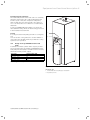
You can store the documents inside the pillar cover.
If you move out or sell the appliance, pass on the documents to the buyer.
With the CE mark, we confirm as equipment manufacturers that the appliances in the geoTHERM exclusive
range satisfy the requirements of the Directive on Electromagnetic Compatibility (Council Directive 89/336/
EEC). The appliances meet the basic requirements of
the Low Voltage Directive (Council Directive 73/23/
EEC).
Furthermore, the appliances satisfy the requirements of
EN 14511 (Heat pumps with electrically-driven compressors, heating, specifications for appliances for space
heating and for warming drinking water) as well as EN
378 (safety and environmentally related specifications
for refrigerating systems and heat pumps).
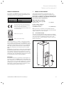
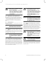
Data badge
An identification plate is attached to the baseplate on
the inside of the geoTHERM exclusive heat pump. The
type designation is located at the top of the front cladding (see also Fig. 4.3, Item 1). In Chapter 7.2 of the Appendix there is a picture of an identification plate for
the benefit of technically-interested customers, and a
table explaining the symbols shown on it.
Fig. 1.1 Removing the pillar cover
Operating Manual geoTHERM exclusive VWS 0020071929_00
3
1 Notes on this manual
2 Safety instructions
1.3
Symbols used
The following hazard classification symbols are used for
information, activities and energy saving tips in this operating manual.
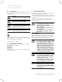
d
H
a
Danger!
Immediate risk of serious injury or death
h
Note!
Useful information and instructions.
Danger!
Danger of burning and scalding!
Caution!
Potentially dangerous situation for the
product and environment.
This symbol points you to energy saving tips. You can
put this setting into effect by means of the heat pump
control system, among other things.
• Symbol for a necessary task
1.4
Applicability of the manual
This operating manual applies exclusively to units with
the following article numbers:
0010007274
0010007275
0010007276
The part number of your unit can be obtained from the
identification plate.
4
2
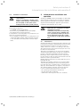
Safety instructions
Observe the following safety instructions and regulations when operating the heat pump:
• Take advantage of the extensive instruction in the operation of the heat pump provided by your specialist
technician.
• Carefully read through this operating manual.
• Only carry out activities that are described in this operating manual.
H
Danger!
Risk of burning as a result of contact
with heat pump components!
High temperatures can appear on heat
pump components.
Do not touch any uninsulated pipes on
the heat pump.
Do not remove any of the cladding sections (apart from the pillar cover, see
Chap. 1.2).
2.1
Coolant
The heat pump is delivered with an operational filling of
R 407 C coolant. This is a chlorine-free coolant which
does not affect the Earth's ozone layer. R 407 C is neither a fire hazard nor an explosion risk.
a
Caution!
This appliance contains R 407 C coolant.
The coolant must not be allowed to escape into the atmosphere. R 407 C is a
fluorinated greenhouse gas covered by
the Kyoto Protocol, with a GWP of 1653
(GWP = Global Warming Potential).
Before the appliance is disposed of, the
coolant it contains must be completely
drained into a suitable vessel so that it
can then be recycled or disposed of in
accordance with the regulations.
d
Danger!
Risk of injury from freezing as a result
of contact with the R 407 C coolant!
Escaping coolant can cause freezing if
the exit point is touched:
Do not inhale gases or vapours emanating from leaks in the coolant circuit.
Avoid contact with the skin and eyes.
h
Note!
R 407 C presents no danger in normal
use and under normal conditions. With
improper use, however, it can cause injury and damage.
Operating Manual geoTHERM exclusive VWS 0020071929_00
Safety instructions 2
Information on the installation and operation 3
2.2
Prohibition on alterations
d
Danger!Inappropriate alterations can
cause injuries!
Under no circumstances should you attempt to make changes or alterations to
the heat pump or other parts of the
heating and hot water system yourself.
The prohibition applies to:
— geoTHERM exclusive heat pumps,
— the Vicinity of geoTHERM exclusive heat pumps,
— the Supply lines for water and power.
For alterations to the heat pump or its peripherals, you
must call on a qualified engineer.
• Do not damage or remove seals or locking devices on
components. Only suitably qualified heating engineer
or our customer service may remove sealed components.
3
Information on installation and
operation
Vaillant geoTHERM exclusive heat pumps are built using
state-of-the-art technology and according to standard
safety regulations and must be installed by a qualified
expert technician taking the applicable specifications,
regulations and guidelines into account.
d
Danger!
Risk to life as a consequence of using
unqualified personnel!
Installation, inspection and repair may
only be carried out by a qualified engineer. In particular, working on the electrical components and on the coolant
circuit requires an appropriate qualification.
3.1
Intended use
Vaillant heat pumps are built using state-of-the-art technology and according to standard safety rules and regulations. Nevertheless, there is still a risk of injury or
death to the user or others or of damage to the device
and other property in the event of im-proper use or use
for which it is not intended.
This unit is not intended for use by persons (including
children) having limited physical, sensory or mental capacities or who have inadequate experience and/or
knowledge, unless supervised by a person responsible
for their safety or who has been given instructions from
them as to how to operate the unit.
Children must be supervised to ensure that they do not
play with the unit.
The units are intended as heaters for closed hot-water
central heating installations and for hot water generation. Any other use or extended use is considered to be
improper. The manufacturer or supplier is not liable for
any resulting damage. The user alone bears the risk.
It is also considered as intended use to observe:
— the operating and installation instructions
— all other applicable documents
— adherence to the inspection and care conditions.
Operating Manual geoTHERM exclusive VWS 0020071929_00
5
3 Information on the installation and operation
d
Danger!
Risk to life as a consequence of improper
use of the installation.
There is a risk of death or serious injury
to the user or third parties or of damage
to the device and other property in the
event of improper use or use for which it
is not intended.
3.2
Requirements of the installation site
The installation site must be dimensioned such that the
heat pump can be properly installed and maintained.
• Ask your heating engineer which currently applicable
national building regulations must be observed.
The installation site must be dry and generally frostproof.
3.3
Cleaning and care
Do not use any scouring or cleaning agents that could
damage the cladding.
h
Note!
Clean the exterior of your heat pump
with a damp cloth and a little soap.
3.4
Checking the operating condition of the heat
pump
In contrast to heaters that operate using fossil fuels, no
complex maintenance work is necessary for the Vaillant
geoTHERM exclusive heat pump.
h
h
Note!
The cold water stop valve is not part of
the heat pump scope of supply. It is fitted on site by your heating engineer. He
will explain the location and handling of
the component to you.
3.4.2
Filling level and filling pressure of the brine
circuit
Check the brine level or pressure in the brine circuit at
regular intervals. The filling pressure of the brine circuit
("Pressure Heat Source"“) can be checked from the
reading on the heat pump controller (see sect. 5.5). It
should be between 1 and 2 bar. If the brine pressure falls
below 0.2 bar, the heat pump will be shut down automatically and an error message will be displayed.
a
Caution!
Risk of damage from brine escaping from
leaks in the system.
In the event of leaks in the brine circuit
switch off the heat pump to avoid any
further leaking.
Have the leaks repaired by an expert
technician.
a
Caution!
The brine circuit must be filled with the
correct quantity of fluid; otherwise the
system can be damaged.
Note!
Have your installation checked regularly
by an expert technician company to ensure efficient operation of your heat
pump.
3.4.1 Filling pressure of the heating installation
The filling pressure of the heating installation should be
checked at regular intervals. The filling pressure of the
heating installation can be checked from the reading on
the heat pump controller (see sect. 5.5). It should be between 1 and 2 bar. If the water pressure falls below 0.5
bar, the heat pump will be shut down automatically and
an error message will be displayed.
6
a
Caution!
Risk of damage from water escaping
from leaks in the system.
Close the cold water stop valve in the
event of leaks in the hot water pipework.
In the event of leaks in the heating installation switch off the heat pump to
avoid any further leaking.
Have the leaks repaired by an expert
technician.
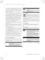
If the filling level of the brine has fallen so far that it is
no longer visible in the expansion tank, you must have
the brine refilled.
Operating Manual geoTHERM exclusive VWS 0020071929_00
Information on the installation and operation 3
3.5
Energy saving tips
Below you will find important tips to help you operate
your heat pump system in an energy and cost-saving
manner.
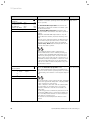
Fig. 3.1 Filling level of the brine expansion tank
It is normal for the filling level of the brine to fall a little
in the first month after the start-up of the system. The
filling level can also vary depending on the temperature
of the heat source. However it should never sink so far
that it is no longer visible in the expansion tank.
a
Caution!
Danger of damage
The brine circuit of your heat pump system must only be filled by authorised
technical personnel.
Check the filling level of the brine circuit
at regular intervals and inform your expert technician company if the filling
level in the brine expansion tank is too
low.
3.5.1 General energy saving tips
You can even save energy by your general behaviour:
— Ventilate correctly:
Do not leave windows or French windows tilted open,
but rather open the windows wide 3 or 4 times a day
for 15 minutes and turn down the thermostatic valves
or room thermostats while ventilating.
— Do not block the radiators to ensure that heated air
can circulate in the room.
— Use a ventilation system with heat recovery.
The optimum exchange of air in the building is always
guaranteed by the use of a ventilation system with
heat recovery (windows no longer need to be opened
for ventilation purposes). If necessary, the air flow can
be matched to your individual requirements with the
ventilation unit's remote control.
— Check that windows and doors are airtight: Keep shutters and blinds closed at night, so that as little heat as
possible is lost.
— If a VR 90 remote control unit is installed as an accessory, do not obstruct it with furniture, etc., so that it
can measure the circulating room air unhindered.
— Think when using water, for example, take a shower
instead of a bath, promptly renew the seals on dripping taps.
3.5.2
3.4.3
Accumulation of condensate (condensation
water)
The evaporator, the brine pumps and the pipes in the
heat source circuit, as well as some components in the
coolant circuit, are insulated in the interior of the heat
pump, so that no condensate can accumulate. If a small
amount of condensate does form, it falls into the condensate pan. The condensate pan is located on the inside, in the lower part of the heat pump. As a result of
the heat generated inside the heat pump, the condensate in the condensate pan evaporates. Small amounts
of the accumulating condensate can be drained off
under the heat pump. In small amounts, accumulating
condensate should not be seen as a fault in the heat
pump.
Operating Manual geoTHERM exclusive VWS 0020071929_00
Economising by the correct use of the
control system
Further economies can be made by the correct use of
the control system on your heat pump.
The heat pump control system helps you to make savings by:
— Correct selection of the heating flow temperature:
Your heat pump controls the heating flow temperature depending on the room temperature you have
set. Therefore select a room temperature that is just
sufficient for your comfort, for example 20 °C. Every
degree over and above that means an increase in energy consumption of around 6 % per annum.
7
3 Information on the installation and operation
— For floor heating use heating curves of < 0.4. For radiator heating, we recommend that they are laid out to
manage with a maximum flow temperature of 50 °C
at the lowest outside temperature; this corresponds to
heating curves of < 0.7.
— An appropriate setting of the hot water temperature:
Only heat hot water as much as is required for consumption. Any further heating results in unnecessary
power consumption, and hot water temperatures of
more than 60 °C also lead to increased lime scale production. We recommend that hot water generation be
achieved without the electric auxiliary heating; by this
method, the maximum hot water temperature is determined by the high pressure cut-out in the heat
pump cooling circuit. This cut-out corresponds to a
maximum hot water temperature of approx. 58 °C.
— Setting of individually suited heating times.
— Select the correct operating mode:
For the times that you are asleep or away, we recommend that you switch the heating to set-back mode.
— Heat uniformly:
By means of a meaningfully constructed heating programme, you can arrange for all the rooms in your
house to be uniformly heated in accordance with your
pattern of use.
— Set the thermostatic valves:
You can adjust the room temperature to suit your individual requirements and ensure effective operation
of your heating installation using the thermostatic
valves in combination with a room temperature regulator (weather compensator).
— The operating times of the circulation pump can thus
be optimally matched to the actual need.
— Consult a qualified engineer. He will adjust your heating installation to suit your personal requirements.
— These and more energy saving tips are provided in
Chap. 5.5. Descriptions of the controller settings and
their energy-saving potential are provided here.
3.6
Recycling and disposal
Most of the raw materials used to manufacture your
heat pump and all its accessories and associated transport packaging can be recycled, and thus have no place
in your household waste.
h
8
a
Caution!
Environmental hazard due to improper
disposal!
The disposal of coolant must only be by
qualified specialists.
3.6.1
Appliance
If your heat pump is identified with this symbol, it does not belong in your household
waste at the end of its useful life. In this case,
make sure that the Vaillant appliance and any
accessories present are properly disposed of
at the end of their useful life.
As this heat pump is not covered by the law regarding
the marketing, return and environmentally friendly disposal of electrical and electronic equipment (ElektroG in
Germany), free disposal at a municipal collection point is
not provided.
3.6.2 Packaging
Leave the disposal of the transport packaging to the
qualified servicing company which installed the appliance.
3.6.3 Coolant
The Vaillant heat pump is filled with R 407 C coolant.
d
Danger!
Risk of injury from freezing as a result
of contact with the R 407 C coolant!
Escaping coolant can cause freezing if
the exit point is touched.
Do not inhale gases or vapours emanating from leaks in the coolant circuit.
Avoid contact with the skin and eyes.
The disposal of coolant must only be by
qualified specialists.
h
Note!
R 407 C presents no danger in normal
use and under normal conditions. With
improper use, however, it can cause injury and damage.
Note!
Please observe the applicable national
legal regulations.
Make sure the old appliance and any accessories are disposed of properly.
Operating Manual geoTHERM exclusive VWS 0020071929_00
Equipment and functional description 4
4
Equipment and functional
description
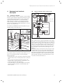
4.2
Mode of operation of the coolant circuit
Cold water
4.1
Principle of operation
Heat pump systems consist of separate circuits in which
liquids or gases transport the heat from the heat source
to the heating system. As these circuits operate with
differing media (brine/water, coolant and heating
water), they are coupled to one another by means of
heat exchangers. In these heat exchangers the heat
passes from a medium at a high temperature to a medium at a lower temperature.
The Vaillant geoTHERM exclusive heat pump uses geothermal energy as its heat source.
Hot water
Heating
system
Diverter valve
Auxiliary
heating
Domestic hot water cylinder
Umschaltventil
Heating water circuit
Heizkreispumpe
3
2
Condenser
Expansion valve Compressor
Evaporator
4
Coolant circuit
1
Heat source circuit
Mixer valve
1/4 Electrical energy
Cooling heat exchanger
3/4 Environmental energy 4/4 Heating energy
Brine pump
Heat source
Fig. 4.2 Operating principle of the heat pump
Fig. 4.1 Using a geothermal heat source
The system consists of separate circuits which are coupled to one another by means of heat exchangers.
These circuits are:
- The heat source circuit, by means of which the energy
from the heat source is transported to the coolant circuit.
- The coolant circuit, which releases its heat to the
heating water circuit by means of evaporation, compression, liquefaction and expansion.
- The heating water circuit, which supplies the heating
and the hot water generator for the domestic hot
water cylinder.
Operating Manual geoTHERM exclusive VWS 0020071929_00
The coolant circuit is connected by means of the evaporator (1) to the environmental heat source, from which it
extracts thermal energy. At the same time, the physical
state of the coolant changes; it evaporates. The coolant
circuit is connected by means of the condenser (3) to
the heating system, to which it releases the heat again.
In so doing, the coolant becomes liquid again; it condenses.
As thermal energy can only pass from a body at a higher temperature to a body at a lower temperature, the
coolant in the evaporator must have a lower temperature than the environmental heat source. On the other
hand, the temperature of the coolant in the condenser
must be higher than that of the heating water in order
to be able to release the heat to it.
9
4 Equipment and functional description
These different temperatures are produced in the coolant circuit by means of a compressor (2) and an expansion valve (4), which are situated between the evaporator and the condenser. The coolant flows in vapour form
from the evaporator into the compressor, where it is
compressed. This causes the pressure and temperature
of the coolant vapour to rise sharply. After this process
it flows through the condenser, where it releases its
heat to the heating water by condensation. It flows as a
liquid to the expansion valve, where it expands significantly and in so doing loses much of its pressure and
temperature. This temperature is now lower than that
of the outside air which flows through the evaporator.
The coolant can thus take up more heat in the evaporator, turning into vapour in the process and flowing to
the compressor. The cycle starts again.
If required, the electric auxiliary heating can be
switched in by means of the integrated controller.
To prevent the formation of condensate in the interior
of the unit, the pipes of the heat source circuit and the
coolant circuit are insulated. Should condensate appear,
however, it is collected in a pan inside the unit and fed
away underneath it. Drop formation under the unit is
thus possible.
geoTHERM exclusive heat pumps by Vaillant are
equipped with an auxiliary cooling function that ensures
a comfortably cool living environment in the summer
when outside temperatures are high. Vaillant heat
pumps with a cooling function utilise the principle of
"passive" cooling which means that the heat is removed
from the rooms and absorbed by the soil via an underfloor heating system, for example. The heating water
absorbs the heat from the rooms during this process
and transfers it via the special switching technology on
the inside of the heat pump to the colder brine which
then transfers the heat to the soil.
4.3
Automatic auxiliary functions
Frost protection
Your controller is equipped with a frost protection function. This function ensures that your heating installation
is protected from frost in all operating modes.
If the outside temperature falls below a value of +3 °C, a
minimum temperature of 5 °C is automatically programmed for each heating circuit.
Cylinder frost protection
This function starts automatically when the actual temperature of the cylinder falls below 10 °C. The cylinder is
then heated to 15 °C. This function is also active in the
"Off" and "Auto" operating modes, regardless of the
timer programmes.
10
Checking the external sensors
The sensors required are determined by the basic hydraulic circuit arrangement specified during commissioning. The heat pump constantly checks automatically
that all sensors are installed and functioning.
Protection from loss of heating water
A pressure sensor recognises a potential loss of water
and switches the heat pump off if the water pressure is
below 0.5 bar gauge pressure. The pressure sensor
switches the heat pump on again when the water pressure rises above 0.7 bar gauge pressure.
Pump seizing and valve seizing protection
To prevent the sticking of the heating, circulation and
brine pump or of the hot water diverter valve UV1, the
pumps and the valve, which have not been in operation
for 24 hours, are switched on every day for approx.
20 sec.
Protection against loss of brine
An analogue pressure sensor monitors possible low
brine pressure and switches the heat pump off if the
brine pressure is ever less than 0.2 bar on the pressure
gauge and error 91 is displayed on the error memory.
The heat pump switches on again when the brine pressure rises above 0.4 bar gauge pressure.
If the brine pressure drops below 0.6 bar on the pressure gauge for more than one minute a warning appears
in menu 1.
Floor protection circuits in all hydraulic systems
without buffer cylinders (with hydraulic plan 6)
If the heating flow temperature in the underfloor heating circuit measured by sensor VF2 continuously exceeds a value of (max. HK temp. + compressor hysteresis + 2 K, default setting: 52 °C) for more than 15 minutes, the heat pump switches off with error message
F.72 (see Chap. When the heating flow temperature falls
below this value again and the error has been reset the
heat pump switches back on.
The maximum heating flow temperature can be changed
via vrDIALOG with the "Maximum heating circuit temperature" parameter.
a
Caution!
Danger of damage to the floor.
Set the value for the floor protection circuit ensuring that it is not high enough
to damage the floor as a result of excessively high temperatures.
Operating Manual geoTHERM exclusive VWS 0020071929_00
Equipment and functional description 4
Freezing protection function
The outlet temperature of the heat source is constantly
measured. If the heat source outlet temperature falls
below a specific value, the compressor temporarily
shuts off with the error message 20 or 21. If these errors occur three times in a row there is a fault-induced
shutdown.
For the geoTHERM VWS heat pumps you can set the
value (Default setting -10 °C) for the freezing protection
in the installation assistant A4.
Cooling
In cooling mode the heat pump performs a cooling function.
You can use the cooling function to set the number of
consecutive days (0 - 99) on which you wish the cooling
system to be in operation.
1
2
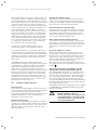
4.4
Design of the geoTHERM exclusive heat
pump
A domestic hot water cylinder with a capacity of 175 litres is integrated into the Vaillant geoTHERM exclusive
heat pump. The heat pump is available in three versions,
which differ mainly in their output.
Type name
Heating output (kW)
Brine water heat pumps (S0/W35)
VWS 63/2 230V
6.0
VWS 83/2 230V
8,1
VWS 103/2 230V
10.5
Table 4.1 Type summary
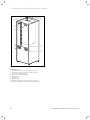
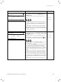
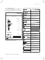
Fig. 4.3 Front view
Key to Fig. 4.3
1 Sticker with the heat pump type designation
2 Operating console
Operating Manual geoTHERM exclusive VWS 0020071929_00
11
4 Equipment and functional description
1
9
2
8
7
6
3
5
4
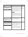
Fig. 4.4 Rear view
Key to Fig. 4.4
1 Hot water connection, domestic hot water cylinder
2 Cold water connection, domestic hot water cylinder
3 Heat source to the heat pump
4 Heat source from the heat pump
5 Heating return
6 Heating flow
7 Handle trough
8 Handle trough/cable grommet, electrical connection
9 Ventilation, heating flow to domestic hot water cylinder
12
Operating Manual geoTHERM exclusive VWS 0020071929_00
Operation 5
5
5.1
Operation
Familiarising yourself with and operating the
controller
2
1
Basic data
6
Date
Day of week
Time
3
Set day
5
4
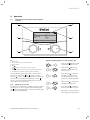
Fig. 5.1 Sample illustration no. 3Fig. 7.1 Overview of operation
Key
1 Menu name
2 Cursor indicating the selected parameter
3 Menu number
4 Dial ,
Set parameter (turn), Select parameter (press)
5 Dial ,
select menu (turn), activate special operating mode (press)
6 Information line (handling request shown in example)
All programming of the heat pump is carried out by
means of the two dials ( and ) on the controller.
The dial is used to select the parameter (by pressing)
and to alter the parameter (by turning). The dial is
used to select the menu (by turning) and to activate
special functions (by pressing).
5.1.1
Calling up the screens
The menus are identified by a number at the top right of
the display. You can access the next menu by turning
the dial. The numbers make it easier to find individual
menus during programming.
Operating Manual geoTHERM exclusive VWS 0020071929_00
Typical operating sequence on the operator level
• Turn the dial until the menu
required has been selected.
• Turn the dial until the parameter to be modified has
been selected.
• Press the dial to mark the
parameter to be modified.
The parameter will be highlighted on a dark background.
• Turn the dial to modify the
parameter setting value.
• Press the dial to mark the
setting value to be accepted.
• Repeat this sequence until all
the settings have been made.
13
5 Operation
5.2
Setting menus and parameters
Setting to date
Modified setting
6
Holiday programming
for cpl. System
Period of
time
Select menu:
• Turn the
1
>06.01.08
08.01.08
2
14.01.08
30.01.08
Room Temp. setpoint
dial: Select
menu e.g. from menu 6 to
7.
>21.04.08
Mo
09:35
>Set day
7
Basic data
>21.04.08
7
>Mon
09:35
>Set weekday
Date
Day of
week
Time
Basic data
• Push the
Date
Day of
week
Time
dial:
Select parameter:
• Turn the
dial:
Modify parameter,
21.04.08
>Mon
09:35
>Set weekday
Modify parameter weekday
from Monday to Tuesday:
21.04.08
7
Basic data
dial: select the
parameter to be modified
e.g. from line 1 day to line
2 weekday (in this
example continue to turn
3 snap-in points).
09:35
Basic data
Select parameter:
• Turn the
Mo
>Set day
Date
Day of
week
Time
Date
Day of
week
Time
12°C
>Set start day
Date
Day of
week
Time
7
Basic data
7
21.04.08
>Tues
09:35
>Set weekday
• Push the
dial:
Accept modification.
Fig. 5.2 Setting menus and parameters
5.3
Controller description
The heating engineer will have set all the operating parameters to preset values during commissioning, so that
the heat pump can function optimally. However you can
individually set and adapt the operating modes and
functions afterwards.
5.3.1 Possible system circuits
The controller can control the following system circuits:
– a heating circuit,
– an indirectly heated hot water storage tank,
– a hot water circulation pump,
– a buffer circuit.
In order to extend the system a buffer circuit can be
used to connect up to six additional mixer circuit modules VR 60 (accessories) each with two mixer circuits.
The controller on the operating panel of the heat pump
is used to programme the mixer circuits. In order to operate under comfortable conditions you can connect the
remote control units VR 90 for the first eight heating
circuits.
14
Operating Manual geoTHERM exclusive VWS 0020071929_00
Operation 5
5.3.2 Energy balance control
Energy balance control applies only to hydraulic systems without buffer cylinders (e.g. hydraulic plan 6).
For economical and fault-free operation of a heat pump,
it is important to regiment the starting of the compressor. The start-up of the compressor is the point at which
the highest loading occurs. With the help of the energy
balance controller it is possible to minimise starts of the
heat pump without compromising the comfort of a
pleasant room atmosphere.
As with other weather-controlled heating controllers the
controller determines a supply set target temperature
by capturing the outside temperature through a heating
curve. The energy balance calculation is carried out
based on this supply set target temperature and the
supply real temperature the difference of which is
measured per minute and added up:
• In the basic display on the graphic display press both
dials at the same time for min. 5 sec.
After that you can select whether to reset only the
timer programme or all values to the default settings.
1 Degree minute [°min] = 1 K Temperature difference in
the Course of 1 Minute
The Code level (menu C1 - C9, D1 - D5, I1 - I5 and A1 - A9)
is reserved for the engineer and protected by a code to
protect it from unintentional modification.
As the operator you can scroll through the menus of the
code level and view the system-specific setting parameters however without changing the values.
In the menus C1 to C9 the engineer sets system-specific
parameters.
The menus D1 to D5 enable the engineer to operate and
test the heat pump in the diagnosis mode.
In menus I1 to I5 you are given general information on
the settings of the heat pump.
Menus A1 to A9 take the engineer through the installation menu to put the heat pump into operation.
The heat pump starts up at a defined heat deficit and
only switches off again when the supplied heat is equal
to the heat deficit.
The larger the preset negative numerical value is, the
longer the periods for which the compressor is kept running or at standstill.
5.3.3 Buffer cylinder charging principle
The buffer cylinder is controlled depending on the supply set target temperature. The heat pump heats when
the temperature of the buffer cylinder head temperature sensor VF1 is smaller than the set target temperature. It continues to heat until the buffer cylinder floor
temperature sensor RF1 has reached the set target temperature plus 2 K.
In the connection to a hot water cylinder charging the
buffer cylinder is also charged when the temperature of
the head temperature sensor VF1 is less than 2 K higher
than the set target temperature (premature reheating):
VF1 < T VL set + 2 K.
5.3.4
Resetting to factory settings
a
Caution!
Inadvertent deletion of specific settings!
When you reset the control system to
the default settings, specific system
settings can be deleted and the system
can sut down. The system does not suffer damage.
Operating Manual geoTHERM exclusive VWS 0020071929_00
5.3.5 Control structure
The Top level display is a Graphics display. It is the
starting point for all the available displays. This display
reappears automatically if you do not actuate any of the
dials for a long time when setting values.
Controller operation is subdivided into four levels:
The Operator level is specified for the operator.
In Sect. 5.4 all of the controller's displays are shown as
a flow diagram. A detailed description of the displays is
contained in Sect. 5.5.
The display and selection of Special function (e.g. the
energy-saving function) is also possible for the operator.
Instructions are given in Sect. 5.6 as to how to activate
the special functions.
The fourth level contains functions for the optimisation
of the system and can only be set by the engineer using
vrDIALOG 810/2.
5.3.6 Adjusting the energy saving functions
Also described in Chap. 5.5 are heat pump settings that
will enable a reduction in your energy costs. This is
achieved by optimum setting of the heat pump's weather-controlled energy balance controller.
This symbol points you to these energy saving tips.
15
5 Operation
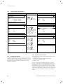
5.4
Flow diagram
Reset to default
settings
Graphics display
We
16.02.08
9:35
Factory setting
Cancel
Time programme
Everything
> Select
> 5 sec.
NO/YES
NO/YES
NO/YES
Graphics display cooling*
Installer Menu
We
16.02.08
9:35
Sparen aktiviert for
> 12:00
> Select stop time
We
16.02.08
9:35
Party function enabled
Energy input display
We
16.02.08
9:35
One-time
DHW tank loading enabled
Mo 21.04.08
Flow Temp. CH
System pressure
Brine pressure
CH : Comp only
Warning message
Warning message
16:49
1
28ºC
1,2bar
1,4bar
Cooling settings *
We
16.02.08
9:35
Cooling function active for
>3days
> Set duration
HK2
Parameters
HK2mode
Heating
Parameter
>Auto
Betriebsart
Set value
day Heizen
>Auto
Night set
back temp.
Raumsolltemp.
>Select
operation mode
Night set back temp.
Domestic hot water
Parameters
Operation mode DHW
Max. DHW temp.
Min. DHW temp.
Current DHW temp.
>Select operation mode
2
2
Domestic hot water
Time programme
>Mo
1
06:00
2
:
3
:
>Select day of the week
20 ºC
15 ºC
20 ºC
15 ºC
5
22:00
:
:
Basic data
Date
Day of week
Time
> Set day of the week
4
Circulation pump
Time programme
>Mo
1
06:00
2
:
3
:
>Select day of the week
> Auto
60 ºC
44 ºC
51 ºC
HK2
5
Time HK2
programme
5
programme
>Mo Time HK2
00:00
24:00
>Mo1 Time programme
2 >Mo 1
: 00:00
: 24:00
3
2
: 00:00:
: 24:00
1 :
:
:
>Select day of 3the week
2
:
:
:
:
>Select day of 3the week
>Select day of the week
7
21.04.08
> Mo
09:35
5
Holiday programming
for cpl. System
Periods
1
>06.01.08
2
14.01.08
Room Temp. setpoint
>Set starting day
5
22:00
:
:
Code layer
8
Code-Nummer:
>0000
Standard code:
1000
>Adjust numeric character
6
08.01.08
31.01.08
12 ºC
Code level only for
expert technicians
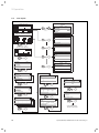
Fig. 5.3 Displays in the User level
16
Operating Manual geoTHERM exclusive VWS 0020071929_00
Operation 5
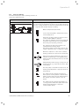
5.5
User level displays
The individual displays on the operating panel are described and explained below.
Display shown
Description
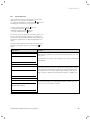
Graphics display (Top-level display)
You can read off the instantaneous state of the system from this display. This is always shown if you have not actuated either of the dials
for a long time while another display is showing.
Outside temperature (here 10 °C)
Source inlet temperature: Temperature sensor;
in the example 9 °C
Under the arrow the output of the heat source
(in the example 10 KW) is displayed.
The extent of darkening of the arrow graphically
shows the energy efficiency of the heat pump
under the given operating conditions.
The output of the heat source must not be
equated with the heating output.
The heating output corresponds to approx. the
output of the heat source + compressor output
When the compressor or the electric auxiliary
heating is switched on, the arrow is shown filled.
>>> Left and right flash when the compressor is
switched on and energy is consequently being
taken from the environment and fed to the heating system.
>>> Right flashes when energy is being fed to the
heating system (e.g. only from the electric auxiliary heating).
The heat pump is in the CH mode. Moreover, the
heating flow temperature is displayed (in the example 30 °C).
The symbol indicates that the domestic hot
water cylinder is being heated or that the heat
pump is in the ready state. The temperature in
the domestic hot water cylinder is also displayed.
The symbol indicates that the heat pump is in
cooling operation. Under the symbol the actual
heating flow temperature is displayed
(in the example 20 °C).
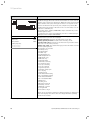
Table 5.1 Settable parameters in the operator level
Operating Manual geoTHERM exclusive VWS 0020071929_00
17
5 Operation
Display shown
Mon. 21.04.08
Current flow temp.
Description
16:49
1
28°C
CH pressure
1.2bar
Brine pressure
1.4bar
Heating only comp.
Warning message
Warning message
Energy input display
Shows the energy extracted from the environment for each of the 12
months of the current year (black bar). White-filled bars represent the
future months of the year; the height of the bar corresponds to the
yield for the month in the previous year (comparison possible). On
commissioning, the height of the bars is zero for all months, as no information is available yet.
The scaling (in the example, 4000 kWh) adapts automatically to the
month's highest value.
Top right the total of the environmental yield since commissioning is
displayed (in the example: 13628 kWh).
Day, date, time as well as flow temperature, heating system pressure
and heat source pressure are displayed.
Current flow temp: Current flow temperature in the unit.
Heating system pressure: Pressure sensor heating circuit.
Pressure heat source: Pressure of the heat source (pressure sensor,
heat source circuit, brine pressure)
Heating only comp.: this status message provides information on the
current operating status.
The following are possible:
CH: Comp. only.
CH: Comp+Aux
CH: Aux only
CH: Comp&aux off
DHW: Comp&aux off
DHW: Comp only
DHW: aux only
Peak Rate: WW
Peak Rate: Stand-by
Acceleration mode
Frost prot. Heating
Frost prot. Cylind.
Legionella protect.
Automatic pump spin
Floor drying
Venting mode
Fault shutdown: heating
Error shutdown: heating
Fault shutdown: DHW
Error shutdown: DHW
Malfunction
Blocking error
Operation interlock
CH Comp overrun
WW Comp overrun
Cooling & WW
CH return too high
Under critical operating conditions a warning message is displayed in
both lower display lines. These lines are empty when the operating
conditions are normal.
Table 5.1 Adjustable parameters at the operator level (contd.)
18
Operating Manual geoTHERM exclusive VWS 0020071929_00
Operation 5
Display shown
HK2
Parameters
Description
2
Operating mode heating
The Room set target temperature is the tempera- Room set target
temp.: 20°C
ture to which the heating should be regulated in the
operating mode "Heat" or during the time slots.
Set-back temp.:
15°C
>Auto
Set value day
22°C
Night set back temp.
15°C
>Select operating mode
Factory setting
Note: Select a room temperature that is just high
enough to ensure your personal well-being
(e.g. 20 °C). Each degree over and above the set
value means an increase in energy consumption of
around 6 % per annum.
The Set-back temperature is the temperature to
which the heating is regulated during the set-back
period. An individual set-back temperature can be
set for each heating circuit.
The set operating mode determines under which
conditions the assigned heating circuit or hot water
circuit should be regulated.
The following operating modes are available for
heating circuits:
Auto: The operation of the heating circuits alternates between the Heating and Energy Saving operating modes in accordance with a settable timer programme.
Eco: The operation of the heating circuits alternates
between the Heating and Off operating modes in accordance with a settable timer programme. The
heating circuit is switched off during the set-back
period provided the frost protection function (which
depends on the outside
temperature) is not activated.
Heating: The heating circuit operates at the room
set target temperature regardless of any settable
timer programme.
Energy sav: The heating circuit operates at the setback temperature regardless of any settable timer
programme.
Off: The heating circuit is off, provided that the frost
protection function (depending on the external temperature) is not activated.
Note:
Additional heating circuits are displayed, depending
on the system configuration.
Table 5.1 Adjustable parameters at the operator level (contd.)
Operating Manual geoTHERM exclusive VWS 0020071929_00
19
5 Operation
Display shown
Description
Factory setting
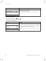
For connected domestic hot water cylinders and the Min. hot water
circulation circuit the operating modes Auto, On and temp. 44 °C
Auto Off are possible.
4
DHW loading
Parameters
Operating mode WW
Auto
Max. DHW temp.
60°C
60°C
Min. DHW temp.
44°C
44°C
Cylinder temp. REAL
51°C
>Select set target temperature
The maximum WW temperature determines the
temperature to which the domestic hot water cylin51°C
der should be heated.
The minimum WW temperature determines the
limit below which the domestic hot water cylinder is
heated.
Note: The maximum WW temperature is only displayed when the auxiliary hot water heating is enabled.
Without electric auxiliary heating, the WW temperature is limited by the pressure sensor control shutoff in the cooling circuit and cannot be adjusted!
Cylinder temp. REAL: Current temperature in the
domestic hot water cylinder.
We recommend that hot water generation be
achieved without the electric auxiliary heating. by
this method, the maximum WW temperature is determined by the high pressure cut-out in the heat
pump cooling circuit. This cut-out corresponds to a
maximum hot water temperature of 58 °C. In order
to keep the heat pump starts to an absolute minimum as low a min. hot water temperature as possible should be selected.
5
HK2
Time programme
>Mon
1
00:00
24:00
2
:
:
3
:
:
You can set the heating times for each heating cir- Mo. – Su.
0:00 – 24:00 hours
cuit in the HK2-Timer programme menu.
Up to three heating times can be programmed per
day or block. The control system operates according
to the heating curve and the room setpoint temperature.
>Select weekday/Block
The set back times can be dispensed with, depending
on the tariff agreement with power company (VNB)
or the construction of the house.
Power companies offer their own discounted tariffs
for heat pumps. It can make sense on economic
grounds to make use of the more favourable offpeak power.
In low-energy houses (in Germany standard as from
1st February 2002 energy conservation regulation)
the room temperature reduction can be dispensed
with owing to low heat losses.
The desired set-back temperature must be set in
menu 2.
Table 5.1 Adjustable parameters at the operator level (contd.)
20
Operating Manual geoTHERM exclusive VWS 0020071929_00
Operation 5
Display shown
5
DHW loading
Time programme
>Mon
1
06:00
22:00
2
:
:
3
:
:
Description
Factory setting
You can set the times at which the domestic hot
water cylinder is heated in the "WW Timer Programme" menu.
Up to three times can be programmed per day or
block.
Mon – Fri
6:00 – 22:00 hrs.
Sat
7:30 – 23:30
Su.
7:30 – 22:00
>Select weekday/Block
The hot water generation should only be active at
times when really hot water is to be run. Please set
this timer programme to your minimum requirements.
As an example, for working people a window from
6.00 – 8.00 hrs. and a second window from 17.00 –
23.00 hrs.can minimise the energy consumption due
to hot water generation.
5
Circulation pump
Time programme
>Mon
1
06:00
22:00
2
:
:
3
:
:
You can set the times at which the circulation pump
is to be operational in the "Circulation Pump Timer
Programme" menu.
Up to three times can be programmed per day or
block.
If the hot water operating mode (see menu 3) is
set to "ON", the circulation pump runs continuously.
Mon – Fri
6:00 – 22:00 hrs.
Sat
7:30 – 23:30
Su.
7:30 – 22:00
>Select weekday/block
The timer programme Circulation Pump should correspond to the
timer programme Hot Water, if necessary the time
slots could be selected even more restrictively.
If the desired hot water temperature is obtained
quickly enough without switching on the circulation
pump, the circulation pump can likewise be deactivated.
In addition, you can briefly activate the circulation
pump by means of electronic pushbutton switches
mounted in the immediate vicinity of the taps and
connected to the heat pump (the same idea as stairwell lighting). The operating times of the circulation
pump can thus be optimally matched to the actual
need.
Consult your expert technician about doing this.
Table 5.1 Adjustable parameters at the operator level (contd.)
Operating Manual geoTHERM exclusive VWS 0020071929_00
21
5 Operation
Display shown
Description
Period of
time
1
>06.01.08
08.01.08
2
14.01.08
30.01.08
>Set start day
For the controller and its connected system components it is possible to programme two holiday periods with the introduction of the date. Moreover, the
desired target room temperature can be set for holidays, i.e. regardless of the preset timer programme.
After the holiday time has elapsed, the controller au12°C tomatically goes back to the previously selected operating mode. The holiday program can be activated
only in auto and eco operating mode.
Connected cylinder charging circuits or circulation
pump circuits are automatically switched to OFF operating mode during the holiday timer programme.
6
Holiday programming
for cpl. System
Room Temp. setpoint
Factory setting
Period 1:
01.01.2003 –
01.01.2003
Period 2:
01.01.2003 –
01.01.2003
Room Temp.
setpoint 15 °C
Connected cylinder charging circuits or circulation
pump circuits are automatically switched to OFF operating mode during the holiday timer programme.
Prolonged periods of absence can be set in the display "Programme holidays". The target temperature
during this period should be selected to be as low as
possible.
During this period hot water generation is not in operation.
7
Basic data
Date
Day of
week
Time
21.04.08
Mo
You can set the current Date, the Day of the week
and the current Time, if DCF radio clock reception is
not possible, in the “Basic Data”menu.
These settings apply to all connected system components.
09:35
>Settable values
8
Code layer
Code number:
>0 0 0 0
>Set figures
To access the Code level (Installer level), the appropriate code must be entered.
To view setting parameters without entering the
code, you must press the dial once. You can then
view all parameters of the code level by turning the
dial but not change them. As operator, without entering the code, you can view all menus in the code
level however not modify them.
Caution! Do not try to access the code level by making arbitrary entries in the code level. Unintentional
modification of the system-specific parameters can
cause malfunctions or damage to the heat pump.
Table 5.1 Adjustable parameters at the operator level (contd.)
22
Operating Manual geoTHERM exclusive VWS 0020071929_00
Operation 5
5.6
Special functions
Special functions can be selected only from the basic
display. To do so press the left-hand dial .
To change the parameter, you must turn the dial. The
following special functions can be selected:
•
•
•
•
Energy saving function: Press dial once.
Party function: Press dial twice.
One-time charging: Press dial 3 x.
Cooling operation: Press dial 4 x
To activate one of the functions, you merely have to select it. In the energy saving function it is additionally
necessary to enter the time until which the energy saving function (regulation to set-back temperature) is to
apply.
The basic display appears either after the function has
elapsed (reaching the time) or by pressing the dial
again.
Display shown
We
16.02.08
Description
9:35
Energy saving enabled
Saving function:
With the saving function you can set back the heating times for a settable period.
Enter the time for the end of the saving function in the format hh:mm
(hour:minute).
>Select end time
We
16.02.08
9:35
Party function enabled
We
16.02.08
one-time
9:35
Party function:
With the party function you can continue the heating and hot water
times beyond the next switch-off time up to the next heating start.
The party function can only be used for the heating circuits or hot
water circuits for which the operating mode "Auto" or "ECO" is set.
One-time charging:
This function allows you to charge the hot water cylinder once, regardless of the current time program.
DHW tank loading enabled
Table 5.2 Special functions
Operating Manual geoTHERM exclusive VWS 0020071929_00
23
5 Operation
Display shown
We
16.02.08
Description
9:35
Cooling function active for
> 3 Days
Cooling operation:
Cooling duration: OFF/1 to 99 days.
If the cooling operation is active,
– the symbol of an ice crystal appears in the graphic display.
Table 5.2 Special functions (ctnd.)
• Reset to default setting: Keep dial and dial
pressed for longer than 5 seconds. After that you can
select whether to reset only the timer programme or
all values to the default settings.
Display shown
We
21.04.08
Factory setting
Cancel
Time programme
Everything
Description
The default settings are re-established.
9:35
Caution! Ensure that a qualified technician performs the default setting reset. The system-specific settings are reset. The system can be
NO/YES
shut down. The system does not suffer damage.
NO/YES
NO/YES
>Settable values
Press both dials for at least 5 seconds to request the menu default
setting.
Table 5.3 Re-establishing the default setting
24
Operating Manual geoTHERM exclusive VWS 0020071929_00
Operation 5
5.7
Starting up the heat pump
The start-up of your heat pump was carried out after installation by your expert technician company.
A repeated start-up will not even be necessary in the
event that your heat pump disconnects from the mains
unexpectedly, for example as a result of a voltage drop
(power cut, circuit breaker defective, circuit breaker deactivated). Your geoTHERM heat pump has an automatic reset function, i.e. the heat pump reverts automatically to its starting condition, provided no fault is present
in the heat pump itself. Find out what to do in the event
of a fault in Chap. 5.10.
5.8
Shutting down the heat pump
The heat pump can only be shut down via the control
panel by deactivating the heating and hot water generation functions in the respective menus (see
Chap. 5.4 Displays at user level).
h
Note!
Should it be necessary to remove all
electric power from the heat pump installation, then switch off the circuit
breaker on your heating system.
5.9
Inspection
An annual inspection/maintenance of the unit by a specialist is a prerequisite for continuing operational safety,
reliability and a long working life.
d
Danger!
Inspections / Maintenance work not carried out can result in damage to property and personal injury.
Have inspections maintenance and repairs carried out only by a recognised
expert technician company.
Only genuine Vaillant spare parts may be used for inspections, maintenance and repair work to ensure the
perfect long-term working order of all functions of your
Vaillant appliance and to prevent the approved series
condition from being changed.
Any spare parts which might be required are listed in
the relevant current spare parts catalogues.
Information can be obtained from Vaillant Customer
Service Centres.
Operating Manual geoTHERM exclusive VWS 0020071929_00
5.10
Troubleshooting and Diagnosis
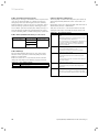
5.10.1 Error messages on the Controller
Error messages appear roughly 20 seconds after the
error has occurred in the display and are written in the
error memory of the controller if the error persists for
roughly 3 minutes. The engineer can then call up the
error message from the memory at a later date.
I1
Error History
Fault number
>1
Fault code
41
16.02.08
07:18
Error CH circuit
Sensor T3 heat source
Fig. 5.4 Error message in the error memory Menu I1
The geoTHERM control system has various malfunction
types:
– Malfunction of Komponents which are connected via
eBUS.
– Temporary Shutdown
The heat pump remains in operation. The error is displayed and disappears independently when the cause
of the fault is removed.
– Fault-induced Shutdown
The heat pump is shut down. It can only be restarted
after the cause of the fault has been removed by the
expert technician and the error reset.
– Moreover, Other Errors/Malfunctions can occur on
the unit or system.
a
Caution!
Heat pump malfunction.
Immediately notify your expert technician if error messages appear on the display on the operating panel which are
not listed in tables 5.4 to 5.7.
Do not attempt to remove the source of
the malfunction yourself.
h
Note!
Not all of the following listed malfunctions have to be dealt with by an expert
technician.
If you are unsure whether you can remedy the fault yourself or not or if the
error occurs repeatedly contact your expert technician or Vaillant customer
service.
25
5 Operation
5.10.2 Activating emergency mode
Depending on the type of malfunction the expert technician can set the heat pump to continue operation in
emergency mode (via an integrated electric auxiliary
heating) until the cause of the error is remedied, and either for heating operation (display "heating priority"),
for hot water operation (display "hot water priority") or
for both (display "heating priority/hot water priority"),
see the following tables, column "emergency operation".
5.10.3 Errors/malfunctions that you can resolve
Malfunction sign
Noise in the heating
circuit.
5.10.5 Temporary malfunctions
The heat pump is shut down temporarily and starts up
again independently when the cause of the fault is removed.
Depending on the error the heat pump switches back on
automatically after 5 or 60 minutes.
Take note of the error code and text and discuss this
during the next inspection with the expert technician.
Fault code
20
Possible cause
Solution
Dirt in the heating Bleeding heating
circuit.
circuit.
Faulty pump.
Error text/description
Frost protection heat source monitoring source
outlet
Temperature difference of the heat source > set
value "permitted temp. difference"
This error message is deactivated as standard and
can only be activated via vrDIALOG parameter
"permitted temp. difference" (20 K difference
means deactivated).
Air in the heating
circuit.
22
Frost protection heat source over. source outlet
Table 5.4 Other Malfunctions
5.10.4 Warnings
The following warning messages do not cause a malfunction in the operation of the heat pump. The heat
pump is not shut down.
Take note of the error code and text and discuss this
during the next inspection with the expert technician.
Fault code
26
36
Error text/description
Overheating on compressor pressure side
Low brine pressure
Table 5.5 Warning messages, no shutdown
Source outlet temperature too low
(<parameter freezing protection in menu A4)
27
Coolant pressure too high
The integrated high pressure switch tripped at
30 bar (g).
The heat pump cannot be restarted until after 60
min. at the earliest.
28
Coolant pressure too low
The integrated low pressure switch tripped at
1.25 bar (g).
29
Coolant pressure outside the range
If the error occurs twice in a row the heat pump
cannot be started until after 60 min. at the earliest.
Table 5.6 Temporary malfunctions
26
Operating Manual geoTHERM exclusive VWS 0020071929_00
Operation 5
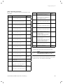
5.10.6 Fault-induced shutdown
Errors could occur which result in the shutdown of the
heat pump.
Fault code
Error text/description
32
Error heat source sensor T8
Fault code
Error text/description
72
Flow temperature too high for
underfloor heating
Emergency
mode
possible
Short-circuit in the sensor
81
33
possible
Error 27 has occurred three times in a
row
Coolant pressure too low check heat
possible
source
possible
Error 28 has occurred three times in a
row
Coolant pressure outside the range
possible
83
Error brine pressure sensor
short-circuit in the pressure sensor
40
Error comp outlet sensorT1
84
Error 29 has occurred three times in a
row
Short-circuit in the sensor
41
Error heat source sensor T3
possible
90
Short-circuit in the sensor
42
Error HP return sensor T5
Error HP flow sensor T6
91
possible
Error external sensor AF
_
Brine pressure too low
possible
Pressure <0.2 bar
Heat pump shuts down and goes into
operation automatically when the
pressure rises above 0.4 bar
Short-circuit in the sensor
44
Heating system pressure too low
Pressure <0.5 bar
Heat pump switches off and starts up
automatically when the pressure
increases to over 0.7 bar
possible
Short-circuit in the sensor
43
Flow temperature is for 15 min. higher
than a set value (max. HK temp. +
compr. hysteresis + 2 K).
Coolant pressure too high
possible
Error heat circuit pressure sensor
short-circuit in the pressure sensor
34
Emergency
mode
_
possible
96
Error - sensor fault
possible
Short-circuit in the sensor
Short circuit in pressure sensor
45
Error DHW tank sensor SP
possible
97
no power for compressor
possible
Short-circuit in the sensor
Table 5.7 Fault-induced shutdown (ctnd.)
46
Error HB flow sensor VF1
possible
• Consult your expert technician about doing this.
Short-circuit in the sensor
47
Error HB return sensor RF1
possible
Short-circuit in the sensor
48
Error flow sensor VF2
Short-circuit in the sensor
WW
operation
possible
52
Sensors are not suited to the
hydraulic plan
_
60
Frost protection heat source
monitoring source outlet
possible
62
Error 20 has occurred three times in
a row
Frost protection heat source
monitoring source outlet
h
Note!
Only an expert technician can remedy
the fault and reset the error code.
Once the expert technician has remedied the error and
reset the error he can restart the heat pump.
possible
Error 22 has occurred three times in a
row
Table 5.7 Error shutdown
Operating Manual geoTHERM exclusive VWS 0020071929_00
27
6 Warranty and customer service
6
Warranty and customer service
6.1
Vaillant warranty
Vaillant provide a full parts and labour warranty for this
appliance.
The appliance must be installed by a suitably competent
person in accordance with the Gas Safety (Installation
and Use) Regulations 1998, and the manufacturer’s instructions. In the UK ‘CORGI’ registered installers undertake the work in compliance with safe and satisfactory
standards.
All unvented domestic hot water cylinders must be installed by a competent person to the prevailing building
regulations at the time of installation (G3).
Terms and conditions apply to the warranty, details of
which can be found on the warranty registration card included with this appliance.
Failure to install and commission this appliance in compliance with the manufacturer’s instructions may invalidate the warranty (this does not affect the customer’s
statutory rights).
6.2
Vaillant Service
To ensure regular servicing, it is strongly recommended
that arrangements are made for a Maintenance Agreement. Please contact Vaillant Service Solutions
(0870 6060 777) for further details.
28
Operating Manual geoTHERM exclusive VWS 0020071929_00
Appendix 7
7
7.1
Appendix
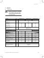
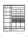
Technical data
a
Caution!
R 407 C is a chlorine-free coolant which
does not affect the ozone layer. Nevertheless, servicing work on the cooling
circuit should only be carried out by authorised specialists.
Description
Unit
Article number
-
Height with connections
Width
Depth without pillars
Depth with pillars
Total weight
- With packaging
- Without packaging
- Ready for operation
Transport weight
- Domestic hot water cylinder module
- Heat pump module
Rated voltage
- Heating circuit/Compressor
- Control circuit
- Auxiliary heating
Fuse, slow-blow
- Unblocked mains supply
Alternative operation (as-delivered
condition 4 kW)
Parallel operation
dual-circuit supply, heat pump tariff
- Compressor, single
- Auxiliary heating 2/4 kW, single
Dual-circuit supply, special tariff
- Alternative operation (as-delivered
status 4kW)
Parallel operation
- Pumps and controllers
Start-up current
- Without start-up current limiter
- With start-up current limiter
Rated output
- Min. for B-5W35
- Max. for B20W60
- Auxiliary heating
mm
mm
mm
mm
EN 60529 level of protection
Hydraulic connections
- Heating circuit flow and return
- Heat source flow and return
- Cold/hot water
-
VWS 63/2 230 V
VWS 83/2 230 V
VWS 103/2 230 V
0010007274
0010007275
0010007276
1930
600
650
840
kg
kg
kg
231
216
402
239
224
411
242
227
415
kg
kg
-
100
106
100
114
100
117
1/N/PE 230 V 50 Hz
1/N/PE 230 V 50 Hz
1/N/PE 230 V 50 Hz
A
16/20
25/25
A
25/35
35/50
A
A
16
16/20
25
16/20
25
16/20
16/20
25/25
25/25
A
A
25/35
4
35/50
4
35/50
4
A
A
58
< 45
76
< 45
97
< 45
kW
kW
kW
1.4
2.8
2/4
1.9
4.0
2/4
2.4
4.9
2/4
A
mm
mm
mm
IP 20
G 1 1/4", Ø 28
G 1 1/4", Ø 28
R 3/4"
Table 7.1 Technical data
Operating Manual geoTHERM exclusive VWS 0020071929_00
29
7 Appendix
Description
Integrated domestic hot water cylinder
- Contents
- Max. operating pressure
- Max. temperature with heat pump
- Max. temp. with heat pump and
auxiliary heating
Heat source circuit (brine circuit)
- Brine type
- Max. operating pressure
- Min. inlet temperature
- Max. inlet temperature
- Nominal flow rate dT 3K
- Residual head dT 3K
- Nominal flow rate dT 4K
- Residual head dT 4K
- Electrical power consumption - pump
CH circuit
- Max. operating pressure
- Min. flow temperature
- Max. flow temperature
- Nominal flow rate dT 5K
- Residual head dT 5K
- Nominal flow rate dT 10K
- Residual head dT 10K
- Electrical power consumption - pump
Refrigerant Circuit
- Coolant type
- Quantity
- Number of revolutions EX valve
- Permissible operating overpressure
- Compressor type
- Oil
- Oil filling quantity
Unit
VWS 63/2 230 V
VWS 83/2 230 V
VWS 103/2 230 V
l
MPa (bar)
°C
°C
175
1 (10)
55
75
MPa (bar)
°C
°C
l/h
mbar
l/h
mbar
W
1453
335
1090
433
132
Ethylene glycol 30 %
0.3 (3)
-10
20
1936
277
1452
397
132
2530
216
1898
398
195
1061
386
517
490
93
0.3 (3)
25
62
1375
324
697
460
93
1803
399
848
580
132
MPa (bar)
°C
°C
l/h
mbar
l/h
mbar
W
1.3
R 407 C
2.2
9.0
2.9 (29)
Scroll
Ester
1,45
bar
bar
bar
bar
ba r
ºC
min
min
4
6
10
3.5
7
95
113
88
4
6
10
3.5
7
95
98
74
4
6
10
3.5
7
95
86
60
B0W35 dT5
- Heating output
- Power consumption
- Performance figure/COP
kW
kW
-
6.0
1.4
4.2
8,1
1.9
4.2
10.5
2.5
4.2
B5W55
- Heating output
- Power consumption
- Performance figure/COP
kW
kW
-
6.3
2.1
3.0
8.6
2.8
3.0
10.8
3.5
3.1
Maximum passive cooling output
under the following conditions: heating
flow VL = 18 °C and
heating return RL = 22 °C!
Sound output
kW
3.8
5.0
6.2
dbA
48
49
50
Conforms to safety regulations
-
CE mark
Low Voltage Directive 73/23/EWG
EMC Directive 89/336/EWG
EN 60335
ISO 5149
DHW circuit
Expansion vessel
Expansion valve setting
Maximum water supply pressure
Pressure reducing valve
Temperature and pressure relief valve
setting
Heat up time
Recovery time
Heat pump performance data
kg
MPa (bar)
l
1.9
9.0
2.05
9.0
1,45
Table 7.1 Technical data (cont.)
30
Operating Manual geoTHERM exclusive VWS 0020071929_00
Appendix 7
7.2
Identification plate
An identification plate is attached to the baseplate on
the inside of the geoTHERM exclusive heat pump. The
type designation is located at the top of the front cladding (see Fig. 4.3, Item 2).
Explanation of the symbols on the identification plate
Rated voltage - compressor
Rated voltage - pumps + controller
Vaillant GmbH Remscheid / Germany
Rated voltage - auxiliary heating
Serial-No. 21054500100028300006000001N1
VWS 63/2 230 V
Rated maximum power
IT FR NO LV LT EE ES UK
IP 20
Rated power - compressor, pumps
and controller
1/N/PE 230V 50Hz
1/N/PE 230V 50Hz
Rated power - auxiliary heating
1/N/PE 230V 50Hz
16 A
6,8
kW
2,8
kW
2/4
kW
< 45
A
Service water tank capacity
175
I
Permissible rated overpressure
1 (10)
MPa (bar)
R407 C
1,9
2,9 (29)
kg
MPa (bar)
Start-up current without start-up
current limiter
Start-up current with start-up
current limiter
16 A
Coolant type
Filling quantity
COP B0/W35
COP B5/W55
4,2
B0/W35
B5/W55
6,0
kW
6,3
kW
Permissible rated overpressure
COP
B0/W35
COP
B5/W55
3,0
B0/W35
21054500100028300006000001N4
B5/W55
Performance figure at a brine
temperature of 0 °C and a heating
flow temperature of 35 °C
Performance figure at a brine
temperature of 5 °C and a heating
flow temperature of 55 °C
Thermal output with a brine
temperature of 0 °C and a heating
flow temperature of 35 °C
Thermal output with a brine
temperature of 5 °C and a heating
flow temperature of 55 °C
CE mark
Fig. 7.1 Example of an identification plate
VDE/GS mark
Read the Operating and Installation
Manual!
Humidity protection class
Ensure proper disposal at the end
of its useful life (not household
waste)
Serial Number
21054500100028300006000001N4
Table 7.2 Explanation of symbols
Operating Manual geoTHERM exclusive VWS 0020071929_00
31
0020071929_00 GB 102008