1
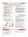
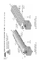
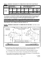
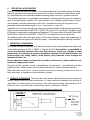
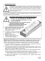
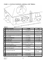
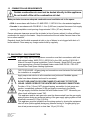
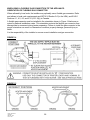
compactSchwank Compact Series Model P40-R Model P40-R GAS-FIRED VENTED ROOM HEATER VENTED OVERHEAD RADIANT TYPE GAS-FIRED VENTED ROOM HEATER VENTED OVERHEAD RADIANT TYPE INSTALLATION / OWNER’S MANUAL WARNING: If the information in these instructions is not followed exactly, a fire or explosion may result causing property damage, personal injury or loss of life. Do not store or use gasoline or other flammable vapours and liquids in the vicinity of this or any other gas fired appliance. WHAT TO DO IF YOU SMELL GAS: Do not try to light any appliance Do not touch any electrical switch; do not use any phone in your building Immediately call your gas supplier from a neighbor’s phone. Follow the gas supplier’s instructions. If you cannot reach your gas supplier, call the fire department. Installation and service must be performed by a qualified installer, service agency or the gas supplier. INSTALLER: Leave this manual with the appliance. CONSUMER: Retain this manual for future reference. FIELD CONVERTIBILITY: This appliance is field convertible to LP gas. Use only the optional gas conversion kit available from the manufacturer. Keep this manual in a secure place . Record for future reference: Model #: Serial #: (located on heater rating label) P40-R I&O Manual IM120801 RD: NOV 2012 RL: 1B - BA NOTICE: This manual is current for this product. This publication, or parts thereof, may not be reproduced in any form, without prior written consent from The Manufacturer. Unauthorized use or distribution of this publication is strictly prohibited. Schwank Group Schwank and InfraSave brands 5285 Bradco Boulevard Mississauga, Ontario,L4W 2A6 PO Box 988, 2 Schwank Way Waynesboro, Georgia 30830 Customer & Technical Services Phone: 877-446-3727 Fax: 866-361-0523 e-mail: [email protected] www.schwankgroup.com www.infrasave.com INSPECT PRODUCT UPON RECEIPT Inspect the carton and heater for concealed damage. Note any damage on the Bill of Lading and make any damage claim to the transport company as soon as possible. P40-R I&O Manual IM120801 RD: NOV 2012 RL: 1B - BA 2 P40-R GAS-FIRED VENTED OVERHEAD HEATER TABLE OF CONTENTS TOPIC TOPIC .........PAGE ……...PAGE 16. HIGH ALTITUDE INSTALLATION ...................27 IMPORTANT INFORMATION - READ FIRST 17. LIGHTING INSTRUCTIONS ...........................27 OPERATING INSTRUCTIONS ........................4 18. RECOMMENDED MAINTENANCE ................ 28 SAFETY WARNINGS.......................................5 19. WIRING DIAGRAMS................................ 29 - 30 START UP ‘SMOKE’........................................6 20. SEQUENCE OF OPERATION .......................31 FLUE VENTING .........................................6, 19 GAS CONNECTION...................................7, 25 21. TROUBLESHOOTING GUIDE.........................32 CLEARANCE TO COMBUSTIBLES ....... 7 - 10 Clearances: Figures & Table................... 8 - 9 STACKING HEIGHT SIGN ............................9 VENT CLEARANCE ........................ 10, 20 - 22 22. SPARK IGNITION CIRCUIT ............................34 SPARK IGNITER SET UP ...............................34 23. FLAME SENSING CIRCUIT ...........................35 24. START– UP / COMMISSIONING SHEET........36 1. APPLICATION ................................................11 PRODUCT DIMENSIONS & DATA 2. LABOR REQUIREMENTS .............................12 25. HEATER DIMENSIONS / WEIGHTS 3. INSTALLATION IN AIRCRAFT HANGARS ...12 ……….38 26. HIGH ALTITUDE & ORIFICE CHART..............39 4. INSTALLATION IN COMMERCIAL GARAGES ......................................................12 28. OPTIONAL ACCESSORIES.............................40 5. INSTALLATIONS OTHER THAN 29. REPLACEMENT PARTS LIST ................ 41 - 42 SPACE HEATING...........................................12 WARRANTY STATEMENT ............BACK PAGE 6. PRE-INSTALLATION SURVEY......................13 7. MOUNTING CLEARANCES...........................13 FIGURES: 8. SERVICE CLEARANCE................................13 FIG 1 - CLEARANCE TO COMBUSTIBLES (3D VIEW) ............8 9. HEATER PLACEMENT GUIDELINES ...........14 FIG 2 - CLEARANCE TO COMBUSTIBLES (END VIEW) .........9 FIG 3 - SERVICE CLEARANCE ...............................................13 10. HEATER INSTALLATION ..............................15 FIG 4 - TYPICAL HEATER SUSPENSION (END VIEW) .........16 10-A SEISMIC RESTRAINT ................................18 FIG 5 - TYPICAL HEATER SUSPENSION (3D VIEW) ............17 10-B HIGH WIND RESTRAINT ...........................18 11. FLUE VENTING............................................. 19 FIG 6 - HEATER DIMENSIONS & SUSPENSION ANGLE OPTIONS ....................................................................17 Side Wall Horizontal Vent.................... 20 - 21 FIG 7 - SEISMIC RESTRAINT..................................................18 Horizontal Vent Terminal Location ............. 22 FIG 8 - HIGH WIND RESTRAINT.............................................18 FIG 9 - HORIZONTAL SIDE WALL VENT CLEARANCES ......20 Vertical Vent Through Roof ....................... 23 FIG 10 - HORIZONTAL SIDEWALL VENT OFFSET................20 12. COMBUSTION AIR REQUIREMENTS ......... 24 FIG 11 - LOCATION OF HORIZONTAL VENT TERMINAL .....22 13. GAS SUPPLY & CONNECTION ................... 25 FIG 12 - VERTICAL ROOF VENT ...........................................23 ORIENTATION OF FLEXIBLE GAS CONNECTION (if applicable) .........................26 FIG 13 - MINIMUM LENGTH VERTICAL ROOF VENT ...........23 14. GAS CONVERSION.......................................27 FIG 15 - INCORRECT ORIENTATION OF FLEXIBLE GAS ....26 FIG 14 - CORRECT ORIENTATION OF FLEXIBLE GAS ........26 15. ELECTRICAL AND THERMOSTAT .............. 27 WIRING DIAGRAMS ..........................................................29, 30 FIG 16 - HEATER DIMENSIONS .............................................38 3 P40-R I&O Manual IM120801 RD: NOV 2012 RL: 1B - BA P40-R I&O Manual IM120801 RD: NOV 2012 RL: 1B - BA 4 WARNING Improper installation, adjustment, alteration, service or maintenance can cause property damage, injury or death. Read and understand this installation and operation manual thoroughly prior to assembly, installation, operation or service to this appliance. Installation and repair must be done by a qualified service person. The appliance should be inspected before use and at least annually by a qualified service person. More frequent cleaning may be required due to excessive dust from activities in the heated space. It is imperative that control compartments, burners and air circulating passageways of the appliance be kept clean. Do not store or use gasoline or other flammable vapours and liquids in the vicinity of this or any other gas fired appliance. Due to high temperatures, this appliance should be located out of traffic and away from furniture and draperies. Children and adults should be alerted to the hazards of high surface temperatures and should stay away to avoid burns or clothing ignition. Young children should be carefully supervised when they are in the same room as the heater. Clothing or other flammable material must not be placed on or near the appliance. Any safety screen or guard removed to service an appliance must be replaced prior to operating the appliance. This appliance has a blocked vent shut-off system (pressure switch). If the vent becomes blocked, the heater will not ignite. Do not tamper with this system. In the event that the appliance fails to operate, contact a qualified service agency. Do not use this appliance if any part has been under water. Immediately call a qualified service technician to inspect the appliance and to replace any part of the control system and any gas control which has been under water. Failure to comply to these instructions could result in personal injury, death, fire and/or property damage. This appliance may have sharp edges and corners. Wear protective clothing such as gloves and protective eye wear when installing or servicing this appliance. 5 P40-R I&O Manual IM120801 RD: NOV 2012 RL: 1B - BA WARNING Improper installation, adjustment, alteration, service or maintenance can cause property damage, injury or death. Read and understand this installation and operation manual thoroughly prior to assembly, installation, operation or service to this appliance. This heater must be installed and serviced only by a trained gas service technician. Do not store or use gasoline or other flammable vapours and liquids in the vicinity of this or any other gas fired appliance. Failure to comply could result in personal injury, death, fire and/or property damage. Do not store or use gasoline or other flammable vapours and liquids in the vicinity of this or any other gas fired appliance. This appliance may have sharp edges and corners. Wear protective clothing such as gloves and protective eye wear when installing or servicing this appliance. CAUTION Start Up ‘SMOKE’ Condition During start up, the heating of material coati ngs used in the production pr ocess of tubes and reflectors will create smoke duri ng the initial period of operation. This condition is normal and temporary . Ensure that there is sufficient ventilation to adequately clear any smoke from the space. Check to ensure that any alarm system is not unduly activated during start up. WARNING Venting Inadequate venting of a heater may re sult in asphy xiation, carbon monoxide poisoning, injury or death. This heater must be directly vented from the space. Venting must be in accordanc e with all local, state, provincial, and nationa l codes (ANSI Z223.1/NF PA 54 in USA; B149. 1 in Canada) and as indicated in this manual. Refer to Sections 11 & 12 P40-R I&O Manual IM120801 RD: NOV 2012 RL: 1B - BA 6 WARNING Gas Connection Improper installation, connection, or adjustment can result in property damage, toxic gases, asphyxiation, injury or death. The gas supply must be connected and tested in accordance with all local, state, provincial, and national codes (ANSI Z223.1/NFPA 54 in USA; CSA B149.1 in Canada). Refer to Section 13 WARNING Clearance to Combustibles Location of flammable or explosive objects, liquids or vapors close to the heater may cause fire or explosion and result in property damage, injury or death. Do not use, store or locate flammable or explosive objects, liquids or vapors in the proximity of the heater. The clearance to combustible material represents the minimum distance that must be maintained between the outer heater surface and a nearby surface. The stated clearance to combustibles represents a surface temperature of 117F° (65C°) above room temperature. It is the installer’s responsibility to ensure that building materials with a low heat tolerance which may degrade at lower temperatures are protected to prevent degradation. Examples of low heat tolerance materials include vinyl siding, fabrics, some plastics, filmy materials, etc. A peel and stick sign is included with this heater to specify the required clearances from the heater to any combustible materials or vehicle. The sign must be posted either adjacent to the heater thermostat or in the absence of such thermostat in a conspicuous location. In addition to stored or stationary material, consideration must also be given to moveable objects such as vehicles and overhead doors, and structural objects such as shelving, sprinkler heads, electrical and gas lines, and electrical fixtures. Do not store any combustible materials or install shelving or other projections within the “Clearance to Combustibles” box - see Figure 1 and Table 1 on the next pages. It is beyond the scope of these instructions to consider all conditions that may be encountered. Consult local authorities such as the Fire Marshall, insurance carrier, or safety authorities if you are uncertain as to the safety or applicability of the proposed installation. Refer to Figure 1 and Table 1 in this manual, and/or the rating label affixed to the burner housing for the certified clearances to combustibles for the heater. 7 P40-R I&O Manual IM120801 RD: NOV 2012 RL: 1B - BA P40-R I&O Manual IM120801 RD: NOV 2012 RL: 1B - BA 8 TUBE/REFLECTOR MOUNTED HORIZONTALLY Always maintain at least the minimum clearance from any combustible material or vehicle. TUBE/REFLECTOR MOUNTED UP TO 30° ANGLE FIGURE 1 MINIMUM CLEARANCES TO COMBUSTIBLES* 3D VIEW - Table 1 also lists values next page TABLE 1 MINIMUM CLEARANCES TO COMBUSTIBLE SURFACES OR MATERIALS* MODELS SUSPENDED HORIZONTALLY SUSPENDED AT AN ANGLE UP TO 30 DEGREES A: TOP C: BELOW S: SIDES A: TOP C: BELOW F: FRONT B: BACK B: BACK inches (cm) inches (cm) inches (cm) inches (cm) inches (cm) AT 30° < 30° inches (cm) P40-R inches (cm) inches (cm) 5 (12.7) 53 (135) 24 (61) 5 (12.7) 53 (135) 36 (91.5) 12 (30.5) 24 (61) E: ‘U’ END of heater : 24” (61 cm) (horizontal or angled) *The clearance to combustible materials represents the minimum distance that must be maintained between the heater and a nearby surface. The stated clearance to combustibles represents a surface temperature of 117F° (65C°) above room temperature. It is the installer’s responsibility to ensure that building materials with a low heat tolerance which may degrade at lower temperatures are protected to prevent degradation. Examples of low heat tolerance materials include vinyl siding, fabrics, some plastics, filmy materials, some coatings and laminated finishes, etc. FIGURE 2 MINIMUM CLEARANCES TO COMBUSTIBLES* END VIEW - See Table 1 above Clearance to Combustibles box around the heater Suspended Horizontally T E: 24” (61 CM) FROM ‘U’ TUBE END Suspended at an angle up to 30° T H H FLOOR FLOOR Calculate Maximum Stack Height ‘H’: (Enter value ‘H’ on the peel and stick label supplied) 53 inches (135 cm) is the required minimum clearance below the heater (‘C’) ‘T’ is measured on site = distance from the bottom of the heater hanger to the floor H = T- 53 inches (135 cm): Do not stack or store higher than ‘H’ under the heater Do not place or store materials or shelvi ng within the Clearanc e to Combustibles Bo x represented by the dotted lines in Figure 2 above 9 P40-R I&O Manual IM120801 RD: NOV 2012 RL: 1B - BA WARNING For your convenience a “peel and stick” sign is provided with this heater. Sign must be posted either adjacent to the IR heating system thermostat or in the absence of such thermostat, in a conspicuous place specifying the required clearances from the heater to the combustibles. Use a permanent marker to record the required clearance dimensions on the sign. ‘H’ is a value calculated at site: (H = T - C) Refer to Figure 1 and Table 1 above Measure the on site distance between bottom of the heater and the floor = ‘T’ inches (cm). The minimum clearance to combustibles below this heater ‘C’ is 53 inches (1135 cm) Subtract ‘C’ 53 inches (135 cm) from ‘T’ (Height above floor) to get value ‘H’. Enter the calculated value ‘H’ on the sign Enter the values as required for the other dimensions: ‘S’ = 24” (61 cm) ‘F’= 36” (91.5 cm) ‘B’ = 12” (30.5 cm) at 30° 24” Or ‘B’ = 24” if mount angle less than 30° 36” POST THIS SIGN ADJACENT TO THE HEATER THERMOSTAT OR IN A PROMINENT LOCATION. 12” VENT CLEARANCE: Clearance from single wall ’C’ vent pipe inside the building is determined by local or national installation codes, but must not be less than 6 inches (15 cm). Clearance from the vent terminal outside the structure are indicated in Section 11 Flue Venting and Figures 9 to 12, pages 19 to 23 for details and requirements for venting. P40-R I&O Manual IM120801 RD: NOV 2012 RL: 1B - BA 10 1. APPLICATION Model P40-R has been design certified to ANSI Z21.86 / CSA 2.32 Vented Gas-Fired Space Heating Appliances (Vented Overhead Heater). Model P40-R may be installed for heating of an indoor residential garage, workshop, or greenhouse. This heater can also be installed in light commercial/industrial locations. This heater must not be installed in any dwelling area of a residence, nor in a basement, mobile home, or recreational vehicle. This heater is not for installation in a Class 1 or Class 2 explosive environment. If the application is in question, consult with local authorities having jurisdiction (Fire Marshall, inspection department, insurance underwriter, or other authority having jurisdiction). Due to high temperatures, the appliance should be located out of traffic and away from furniture and draperies. Children and adults should be alerted to the hazards of high surface temperatures and should stay away to avoid burns or clothing ignition Young children should be carefully supervised when they are in the same room as the appliance Clothing or other flammable material should not be placed on or near the appliance Any safety screen or guard removed to service an appliance must be replaced prior to operating the appliance Installation and repair should be done by a qualified service person. The appliance should be inspected before use and at least annually by a qualified service person. More frequent cleaning may be required due to excessive dust or contaminants from activities in the area of the appliance. It is imperative that control compartments, burners and air passageways of the appliance be kept clean. It is beyond the scope of these instructions to consider all conditions that may be encountered. Installation must conform with local building codes or, in the absence of local codes, with the National Fuel Gas Code, ANSI Z223.1/NFPA 54 in the U.S.A. or the Natural Gas and Propane Installation Code, CSA B149.1 in Canada. The latest edition Electrical Code ANSI/NFPA N0 70 in the U.S.A. and PART 1 CSA C22.1 in Canada must also be observed. Installation of this heater must conform to all heating installation procedures in this manual including suspension, maintenance of clearance to combustibles, connection to the gas and electrical supplies, and ventilation. Revisions to codes and/or standards, may require revision to equipment and installation procedures. In case of discrepancy, the latest codes, standards, and installation manual will take priority over prior releases. 11 P40-R I&O Manual IM120801 RD: NOV 2012 RL: 1B - BA 2. LABOR REQUIRMENTS Two persons are required to safely install th is equipment. SHARP EDG ES - Wear gloves and other required safety protection. 3. INSTALLATION IN COMMERCIAL AIRCRAFT HANGARS Low intensity radiant tube heaters are suitable for use in aircraft hangars when installed in accordance with the latest edition of the Standard for Aircraft Hangars, ANSI/NFPA No 409 in the USA, or the Canadian Natural Gas and Propane Installation Code, B149.1. A. A minimum clearance of 10 ft (3 m) above either the highest fuel storage compartment or the highest engine enclosure of the highest aircraft which may occupy the hangar. The clearance to the bottom of the heater shall be measured from the upper surface of either the fuel storage compartment or the engine enclosure, whichever is higher from the floor. B. A minimum clearance of 8 ft (2.4 m) must be maintained from the bottom of the heater to the floor in other sections of the aircraft hangar, such as offices and shops, which communicate with areas for servicing or storage. Refer to Table 1 for proper mounting clearances to combustibles. C. Heaters must be located so as to be protected from damage by aircraft and other objects, such as cranes and movable scaffolding. D. Heaters must be located so as to be accessible for servicing and adjustment. 4. INSTALLATION IN COMMERCIAL GARAGES AND PARKING STRUCTURES Low Intensity Heaters are suitable for use in commercial garages when installed in accordance with the latest edition of the Standard for Parking Structures, ANSI/NFPA 88A, or the Standard for Repair Garages, ANSI/NFPA No. 88B, or the Canadian Natural Gas and Propane Installation Code, B149.1. An overhead heater shall be located high enough to maintain the minimum distance to combustibles, as shown on the heater rating plate, from the heater to any vehicles parked below the heater. WARNING Overhead heaters shall be installed at least 8 ft (2.4 m) above the floor in commercial garages and parking structures. 5. INSTALLATIONS OTHER THAN SPACE HEATING Use for process or other applications that are not space heating will void the heater certification and product warranty. Process applicat ion requires field inspection and/or certification by loca l authorities having jurisdiction. P40-R I&O Manual IM120801 RD: NOV 2012 RL: 1B - BA 12 6. PRE INSTALLATION SURVEY Carefully survey the area to be heated. It is recommended that a full heating design including heat loss calculation be conducted on the structure or area to be heated. Heater sizing, quantity, and placement must consider available mounting height, sources of greatest heat loss. The certified clearances to combustibles must always be maintained with respect to stored material, moveable objects (vehicles, lifts, overhead doors, etc), sprinkler system heads, furniture and draperies, and other obstructions at the site. Consideration must also be given to vent placement and the allowable length of vent . (see section 11, page 19) Installation must conform with all local, state, provincial and national code requirements including the current latest edition ANSI Z223.1 (NFPA 54) in the U.S.A. and B149.1 installation code in Canada, for gas burning appliances and equipment. The latest edition Electrical Code ANSI/ NFPA N0 70 in the U.S.A. and PART 1 CSA C22.1 in Canada must also be observed. The heating system must have gas piping of the correct diameter, length, and arrangement to provide adequate fuel supply and function properly. A dimensioned layout drawing is advised. 7. MOUNTING CLEARANCES This heater must be mounted wit h at least the minimum clear ances between the heater and combustibles as shown in FIG-1, TABLE 1, Pages 8 & 9. It is the installer’s responsibility to ensure that building materials with a low heat tolerance which may degrade at lower temperatures are protected to prevent degradation. Examples of low heat tolerance materials include vinyl siding, fabrics, some plastics, filmy materials, some coatings and laminated finishes, etc. Ensure adequate clearance around the air intake at the burner to allow sufficient combustion air supply to the heater. Proximity of lights, sprinkle r heads, overhead doors, storage areas , gas and electric al lines, parked vehicles, cranes and any other possible obstruction or hazard must be evaluated. Place the heater so as not to c ause a haz ard to a wall, floor, shelving, curtains, furni ture, or door when open, or impede the free movement of people. 8. SERVICE CLEARANCE: The lower ‘jaw’ of the burner c abinet swings down to provide convenient service access to burner components. Pr ovide a minimum clearance from any wall or obstruction of 6 inches (15 cm) to the access end of the burner housing, and a minimum of 24 inches (61 cm) to any ONE side to allow burner service. (see Figure 2 below) The minimum clearances to combustibles must always be maintained. FIGURE 3 24” (61 cm) Min. 6” (15 cm) Min. 13 P40-R I&O Manual IM120801 RD: NOV 2012 RL: 1B - BA 9. GUIDELINES FOR HEATER PLACEMENT* - SPACE HEATING APPLICATIONS TABLE 2 MODEL P40-R DISTANCE – HEATER LONG AXIS PARALLEL TO WALL GUIDELINE * MOUNTING HEIGHT ft (m) MAXIMUM BETWEEN HEATERS ft (m) HORIZONTAL ft (m) 8 – 18 (2.4 - 5.5) 20 (6) 5 – 12 (5 - 8) ANGLE MOUNTED MINIMUM: COMBUSTIBLE CLEARANCE BEHIND (refer to Table 1) * GUIDELINE MOUNTING HEIGHTS are typical to provide optimum comfort in general space heating applications. Variance from these typical heights can occur in some applications: Higher mounting height due to structure or application requirements For ‘area’ or ‘spot’ heat, or in areas with greater infiltration rates (near overhead doors, etc) where more intense heat is needed to provide better comfort then lower mounting heights are recommended (minimum 8 ft [2.4 m] mounting height) IMPORTANT: Single or multiple heater placement must be such that continuous operation of heaters will not cause combustible material or materials in storage to reach a temperature in excess of ambient (room) temperature plus 117F° (65C°). It is the installer’s responsibility to ensure that building materials with a low heat tolerance which may degrade at lower temperatures than the clearance temperature are protected to prevent degradation. Examples of low heat tolerance materials include vinyl siding, fabrics, some plastics, filmy materials, etc. Refer to “Clearance to Combustibles” information on pages 7 to 10, and Figure 1 and Table 1, and listed on the heater rating plate (on burner housing). P40-R I&O Manual IM120801 RD: NOV 2012 RL: 1B - BA 14 10. HEATER INSTALLATION Inadequate or improper suspension of the tube heater can result in collaps e of the system, property damage, and personal injury or deat h. Suspend the heater from a structural member that can adequate ly support the weight of the heater. Always maintain the required minimum cl earances to combustible materials and vehicles (see pages 7 to 10). It is the installer’s responsibility to ensure that the hardware and structural supports from which the heater is suspended are so und and of adequate s trength to support the weight [86 lb (39 kg)] and expansion forces of the heater. USE CARE & CAUTION WHEN LIFTING HEATER FROM CARTON 1. DO NOT LIFT THE HEATER BY THE REFLECTOR 2. AT LEAST 2 PERSONS ARE REQUIRED TO LIFT AND INSTALL THIS HEATER 3. CHAINS ARE PROVIDED TO LIFT HEATER FROM CARTON AND FOR HANDLING PURPOSES 4. WHEN HANDLING HEATER FROM BENEATH HANDLE BY TUBE NOT REFLECTOR 5. LIFT BOTH ENDS FROM CARTON AT THE SAME TIME TO KEEP THE HEATER HORIZONTAL / LEVEL ALONG ITS LENGTH WHILE HANDLING AND INSTALLING 6. LIFT SAFELY - LIFT WITH YOUR LEGS AND KEEP BACK STRAIGHT - DO NOT BEND OR TWIST. 7. BEWARE - SHARP EDGES! WEAR PROTECTIVE GLOVES AND CLOTHING WHEN HANDLING IMPORTANT: FIRST READ: Review the information on pages 4 to 10 and ensure that installation adheres to the instructions in this manual, and all national and local codes. Refer to pages that follow for illustrations and dimensions that assist in installation. 1. Survey the available structural support, c onsidering the system conf iguration and heat requirements of the area to establish the optimum heater location. 2. The heater can be mounted with t he tube/reflector in a horizontal position, or at 30°. Locating a heater directly under jois ts or beams, and/or installing supplemental support such as angle iron can ensure the integrity of the installation. 3. Hardware with a minimum 100 lb. (30 kg) wo rk load must be used at each heater suspension point. A #2 Lion Chain or equivalent is typically used to suspend the heater. b) If rigid hardware such as 3/ 8” threaded rod is used for suspens ion, swing joints or other means must be provided to allow for system expansion - approximately ½ inch 4. The heater must be supported at 72 inches (183 cm) apart . all four mounting tabs on the 15 hangers that are located P40-R I&O Manual IM120801 RD: NOV 2012 RL: 1B - BA 5. Install the structural fasteni ng hardware and any suspension hardware (chain, etc) prior to removing heater from the carton. Ensure t hat the support hard ware system is firmly fastened to a structural member(s) of sufficient strength and integr ity to support the weight of the heater. 6. The heater comes fully assembled from the factory. For locations where there is constrained access for installation, removal of the burner assembly may assist in the installation of the tube/reflector assembly. Disconnect the spark wire from the igniter and remove the four nuts that fasten the burner to the tube flange. Re-install the burner after the tube system is installed. If the tube/reflector system is to be oriented up to a 30° mounting angle (see below), the burner must be adjusted to a horizontal operating position. Up to 30° Angle Mounting: 7. The tube/reflector system ca n be oriented on the sh ort axis from horizontal to an angle up to 30 degrees. When angle mounted the vent si de of tube must alwa ys be higher than the burner side. The tube/reflector system must be level along its length 8. When the tube/reflector is suspended at an angle up to 30°, the burner mounting flange has a slot pattern that allows adjustment (rotation) of the burner to a hor izontal position for proper operation (see Figure 4 below, and Figure 6 next page). Install the tube/reflector system as above, with tube/reflector assembly angled up to 30° Loosen the 4 nuts (2 or 3 turns) until burner studs can rotate in the flange slots Ensure that the gasket between burner and flange rotates with the burner Tighten the 4 nuts to secure the burner in the horizontal position 9. For seismic and high wind restraint see Sections 10-A & 10-B, page 18. FIGURE 4 HEATER SUSPENSION: HORIZONTAL TO 30° ANGLE P40-R I&O Manual IM120801 RD: NOV 2012 RL: 1B - BA 16 FIGURE 5 TYPICAL SUSPENSION Use all four suspension points plus a chain at the burner eye hook. Hardware capable of supporting minimum 100 lbs (45 kg) at each suspension point. For seismic and high wind restraint see ) Sections 10-A & 10-B. cm 3 18 SERVICE ACCESS: ALLOW A MINIMUM OF 6 ” ( 2 7 INCHES (15 cm) FROM THE ACCESS END OF THE BURNER AND A MINIMUM OF 24 INCHES (60 cm) FROM EITHER SIDE OF THE BURNER TO A WALL OR ANY OBSTRUCTION THAT WOULD RESTRICT OR LIMIT ACCESS TO THE BURNER (SEE SECTIONS 6 & 7 - PRE-INSTALLATION SURVEY AND MOUNTING CLEARANCES) Connect to properly grounded 120V power supply For 30° angle mount: Install the tube system; Loosen 4 nuts holding burner to tube flange; rotate burner to horizontal orientation; re-tighten 4 nuts. (see full instructions previous page) FIGURE 6 HEATER DIMENSIONS & SUSPENSION ANGLE OPTIONS Turbulators (factory installed in tube): Burner side tube: 36” (91 cm) Vent side tube: 90” (229 cm) Vent side always upper Burner always horizontal 17 P40-R I&O Manual IM120801 RD: NOV 2012 RL: 1B - BA 10-A SEISMIC RESTRAINT - LATERAL AND LONGITUDINAL PLANES FIGURE 7 In areas prone to earthquake, or as specified on a project, install lateral and longitudinal seismic restraints as indicated in Figure 11. If the heater location can be impacted by wind (near overhead doors, aircraft hangars, etc) refer to High Wind Restraint section 10-B below. These instructions indicate attachment of suspension and restraint hardware to the heater. The attachment of suspension hardware to the structure will be as required by site structural conditions, installation codes, and/or local engineering specifications. Other types or systems of restraint that are specified by local or national codes, or by project engineering design specifications may be used . Schwank / InfraSave offers optional items: #2 Lion Chain 115 lb work load x 200 ft roll (PN: JL0800-XX); and Safety Snap Hooks (PN: JL-0800-SH = pkg 24; JL-0800-SH-B = pkg 100). All other required seismic mounting hardware is field supplied by the installer. 10-B HIGH WIND RESTRAINT - LONGITUDINAL, LATERAL, AND VERTICAL PLANES In areas with wind conditions that can impact the heater (outdoor, aircraft hangers, etc): in addition to lateral and longiFIGURE 8 tudinal restraint the heater must be reUse Rod for Main Suspension strained from vertical movement. Suspend the heater using 3/8” threaded rod with 3” adjustment turnbuckle at each hanger location to restrain up-anddown movement. Install angled chains for lateral and longitudinal restraint. P40-R I&O Manual IM120801 RD: NOV 2012 RL: 1B - BA 18 WARNING 11. FLUE VENTING Inadequate venting of a heater may result in asphyxiation, carbon monoxide poisoning, injury or death. This heater must be connected to a vent to remove products of combustion from the space. Seal all vent connections with high temperature sealant. Venting must be in accordance with all local, state, provincial, and national codes (ANSI Z223.1/NFPA 54 in USA; B149.1 in Canada) and as indicated below in this manual. THIS HEATER MUST BE VENTED DIRECTLY TO THE OUTSIDE. THE SYSTEM MUST NOT BE OPERATED WITHIN A NEGATIVE AIR CONDITION. ENSURE ADEQUATE AIR SUPPLY TO THE SPACE TO ENSURE THERE IS NO NEGATIVE AIR CONDITION (NEGATIVE PRESSURE IN THE SPACE BEING HEATED). THIS GAS APPLIANCE MUST NOT BE CONNECTED TO A CHIMNEY FLUE SERVING A SEPARATE SOLID-FUEL BURNING APPLIANCE. GENERAL FLUE VENTING REQUIREMENTS It is the sole responsibility of the installer to adhere to all current local codes and/or ANSI Z223.1 / CSA.B149.1 latest editions for all venting requirements, and practices. It is a normal condition that during heat-up and cool-down a tube heater will expand and contract. Allowances for heater expansion must be made in the venting. Improper installation can result in property damage, injury or death. This heater has a positive vent pressure A vent termination cap is supplied with the heater for use with horizontal side wall vent All vent pipe and adapters must be listed and will be supplied locally by others Vent pipe must be minimum 26 gauge single wall type “C” vent pipe of 4” (10 cm) diameter except that portion of vent passing through the wall or roof shall be 4” type “B” vent A minimum 12 inch (30 cm) length of minimum 26 gauge single walled 4” (10 cm) diameter “C” vent pipe is to be installed on the swaged end of the tube before any vent elbow is fitted. Seal all vent connections with high temperature sealant. Vent connections must be secured with three (3) #8 sheet metal screws uniformly spaced around the circumference of the vent pipe. When the vent pipe passes through a cold or unheated area where the ambient temperature is likely to produce condensation of the flue gases, the vent pipe will be insulated with a suitable material as appr oved and s pecified by the insulation manufactur er to withstand temperature up to 460°F (238°C). The vent system must always be adequately supported to prevent sagging. Refer to next pages for minimum and maximum vent length requirements: Horizontal side wall vent: Pages 20 - 21 Vertical roof vent: Page 23 19 P40-R I&O Manual IM120801 RD: NOV 2012 RL: 1B - BA FIGURE 9 - Horizontal Vent - ALL vent pipe and adapters are field supplied A wall thimble is not required through a noncombustible wall. Seal pipe penetration. FIGURE 10 - Horizontal Vent Offset Allow free expansion and contraction of the system, and free flow of vent gas. All Vent Pipe & Adapters Field Supplied continued …….. P40-R I&O Manual IM120801 RD: NOV 2012 RL: 1B - BA 20 HORIZONTAL VENT THROUGH A SIDE WALL: (Vertical vent through roof is on page 23) Refer to General Venting Requirements on page 19 Minimum length of a horizontal side-wall vent: Regardless if a 90° elbow is installed, a Minimum linear 36 inch (3 ft; 91 cm) single wall ‘C’ vent plus minimum 12 inch (30.5 cm) double wall ‘B’ vent through wall Total minimum linear vent length of 48 inches (4 ft; 122 cm) Maximum length of a horizontal side-wall vent: Total Maximum vent length is 15 ft (4.6 m) Each 90° or 45° elbow is equivalent to 5 ft A minimum 12 inch (30.5 cm) double wall ‘B’ vent must be used through the wall The flue vent system must slope downwards approximately 1/4" per foot (63 mm / 300 mm) toward the vent terminal, from the termination of the tube - radiant tube must be level. A maximum of two elbows (90° or 45°; each = equivalent 5 ft) can be installed in a horizontal vent For side wall venting use either Schwank/InfraSave 4” (10 cm) horizontal vent terminal (Part Number: JA-0528-XX - available as an option) or an approved 4” (10 cm) “High Wind” vent termination cap (see clearance information previous page and next page) Install the termination cap a minimum of 6 inches (15 cm) from the outside wall to the inside edge of terminal opening to minimize back pressure caused by turbulent wind conditions (See Fig. 9 above). This also ensures flue gases are directed away from the structure to help protect building materials from degradation by the exhausted flue gases. The vent must be installed to prevent blockage by snow, undue wind pressure on the termination, and to protect building materials from degradation by flue gases. Clearances Required for Horizontal Side Wall Vent : Refer to Figure 9 above, and in particular to Figure 11 and Table 3 next page for specific requirements of codes in the USA and Canada Any values not listed in Table 3 shall be in accordance with local installation codes and the requirements of the gas supplier Footnotes for Table 3 (next page) 1 Installations in Canada in accordance with current CSA B149.1, Natural Gas and Propane installation Code 2 Installations in the USA in accordance with the current ANSI Z223.1 / NFPA 54, National Fuel Gas Code † A vent shall not terminate directly above a sidewalk or paved driveway that is located between two single family dwellings and serves both dwellings ‡ Permitted only if veranda, porch, deck, or balcony is fully open on a minimum of two sides beneath the floor ** Clearance in accordance with local installation codes and the requirements of the gas supplier. 21 P40-R I&O Manual IM120801 RD: NOV 2012 RL: 1B - BA FIGURE 11: LOCATION OF HORIZONTAL (SIDE WALL) VENT TERMINAL TABLE 3 Canada1 Clearance required: USA2 A Above grade, veranda, porch, deck, balcony 12” (30 cm) 12” (30 cm) B To a window or door that may be opened 12” (30 cm) 9” (23 cm) ** ** 12” (30 cm) 9” (23 cm) E Below an unventilated soffit 3” (7.6 cm) 3” (7.6 cm) F To an outside corner 12” (30 cm) 12” (30 cm) G To an inside corner 12” (30 cm) 12” (30 cm) 3 ft (91 cm) within 15 ft (4.5 m) height above meter/regulator ** 3 ft (91 cm) ** 12” (30 cm) 9” (23 cm) 6 ft (1.83 m) 3 ft (91 cm) above if within 10 ft (3 m) horizontally L Above sidewalk or paved drive on public property 7 ft (2.13 m) † ** M Under veranda, porch, deck, balcony 12” (30 cm) ‡ ** C To a permanently closed window D H Below a ventilated soffit within 2 ft horizontal from center of terminal To each side of centerline extended above a meter/regulator assembly I To a service regulator vent outlet J To non-mechanical air supply inlet or combustion air inlet to other appliance K To mechanical air supply inlet See Table footnotes previous page P40-R I&O Manual IM120801 RD: NOV 2012 RL: 1B - BA 22 VERTICAL VENT THROUGH THE ROOF: (Horizontal vent through side wall is on pages 20 - 21) It is the sole responsibility of the installer to adhere to all current local codes and/or ANSI Z223.1 / CSA.B149.1 latest editions for all venting requirements, and practices. Refer to General Venting Requirements on page 19 Any horizontal portion of vent must be miniFIGURE 12 mum 26 gauge single wall type “C” vent pipe of 4” (10 cm) diameter (seal all conApproved nections); vertical portion of vent can be 4” Cap type “B” vent Approved ‘B’ Vent When the vent pipe passes through a cold or unheated area where the ambient temperature is likely to result in condensation of the flue gases, the vent pipe will be type ‘B’ vent or insulated with a suitable material as approved and specified by the insulation manufacturer to withstand temperature up to 460°F (238°C). 24” 60 cm Up 9 to 12 If roof slope exceeds 9:12 consult NFPA-54 ANSI Z223.1 or CSA-B149.1 Use an approved ‘B-vent’ termination cap as supplied by the manufacturer of the listed ‘B-vent’. FIGURE 13 Minimum length of a vertical roof vent: Minimum 12 inch (1 ft; 30.5 cm) single wall ‘C’ vent Plus one 90° “C” vent elbow Plus minimum 36 inch (3 ft; 91.4 cm) double wall ‘B’ vent Total minimum linear vent length of 48 inches (4 ft; 122 cm) plus one 90° ‘C’ elbow Minimum 36” (91.5 cm) ‘B’ Vent ‘C’ to ‘B’ Adapter Minimum 12” (30.5 cm) ‘C’ Vent Thimble 90° ‘C’ Vent Elbow Maximum length of a vertical roof vent: Above minimum requirements must be met A maximum of one 90° elbow (equivalent 5 ft) plus two 45° elbows (each equivalent to 2.5 ft) can be installed in a vertical vent system Refer to local and national codes for maximum allowable venting 23 P40-R I&O Manual IM120801 RD: NOV 2012 RL: 1B - BA 12 COMBUSTION AIR REQUIREMENTS Outside combustion air must not be ducted directly to this appliance. Do not install a filter at the combustion air inlet. Make provision to ensure adequate combustion and ventilation air in the space: USA: In accordance with Section 9.3 ANSI Z223.1 / NFPA-54 for a fan-assisted appliance. 2 2 Canada: In accordance with CSA B149.1: 4 in (2,600 mm ) required free area of air-supply opening [acceptable round opening of approximate 2.25 in (57 mm) diameter]. Ensure adequate clearance around the air intake (at top of burner cabinet) to allow sufficient combustion air supply to the heater. Keep the area around the air intake free and clear of debris or other material. Regularly check that the bird-screened air inlet on top of blower is not clogged with dust or fibrous material. Clean away any foreign matter build-up regularly. 13. GAS SUPPLY - GAS CONNECTION CAUTION: All gas supply piping and appliance connection must be in accordance with local and national codes, ANSI Z223.1 (NFPA 54) in the USA, and the CSA B149.1 Natural Gas and Propane Installation Code in Canada. Model P40-R is an appliance approved as a Vented Overhead Heater under ANSI Z21.86 / CSA 2.32 Vented Gas-Fired Space Heating Appliances. TEST FOR LEAKS: All gas piping and connections must be tested for leaks after the installation is completed. Apply soap suds solution to all connections and joints and if bubbles appear, leaks have been detected and must be corrected. DO NOT USE A MATCH OR OPEN FLAME OF ANY KIND TO TEST FOR LEAKS. NEVER OPERATE THE HEATER WITH LEAKING CONNECTIONS. Provide a 1/8 in (3.2 mm) NPT plugged tapping, accessible for test gauge connection, immediately upstream of the gas supply connection to the heater. The gas supply should be checked first with heater turned “OFF” followed by another check with heater turned “ON”. This appliance and its main gas valve must be disconnected from the gas supply piping system during any pressure testing of the gas supply piping system at test pressure in excess of 1/2 psi (3.5 kPa). This appliance must be isolated from the piping system by closing the equipment shut off valve (field supplied) during any pressure testing of the gas piping system at test pressure equal to or less than 1/2 psi (3.5 kPa). P40-R I&O Manual IM120801 RD: NOV 2012 RL: 1B - BA 24 13. GAS SUPPLY - GAS CONNECTION … continued Provide a 1/8 in (3.2 mm) NPT plugged tapping, accessible for test gauge connection, immediately upstream of the gas supply connection to the heater. The gas supply should be checked first with heater turned “OFF” followed by another check with heater turned “ON”. This appliance and its main gas valve must be disconnected from the gas supply piping system during any pressure testing of the gas supply piping system at test pressure in excess of 1/2 psi (3.5 kPa). This appliance must be isolated from the piping system by closing the equipment shut off valve (field supplied) during any pressure testing of the gas piping system at test pressure equal to or less than 1/2 psi (3.5 kPa).I MPORTANT: Minimum supply line pressure at the inlet to the heater regulator must not be lower than 5.0 inches of water column pressure for natural gas, and not be lower than 10.0 inches of water column pressure for LPG. The supply gas pressure must be checked with all heaters in operation. Installation of a gas line (trap) “drip leg” is required at the inlet connection tee following the pipe drop to the heater. Failure to provide a “drip leg” could result in condensation and foreign matter passing into the gas valve. Failure to install a “drip leg” in the gas line can cause property damage, injury or death and will void the heater warranty. TABLE 4 LINE PRESSURE INCHES WATER COLUMN GAS TYPE MINIMUM MAXIMUM MANIFOLD PRESSURE (tap at gas valve outlet) INCHES WATER COLUMN Natural Gas 5.0 14.0 3.5 LP Gas 11.0 14.0 10.0 NOTE: Access to the manifold pressure test port is located on the top of the valve. A 3/16" Allen Key is required. A manometer should be used to check the manifold pressure. Gauges which measure in ounces or PSI are not accurate enough to measure or set the pressure. GAS CONNECTION Connection between the gas supply piping and the appliance must be in accordance with local and national codes, ANSI Z223.1 (NFPA 54) in the USA, and the CSA B149.1 Natural Gas and Propane Installation Code in Canada. The P40-R is approved as a Vented Overhead Heater and may be rigid piped to the building gas supply (also see Flexible Gas Connection Option, next page). 25 P40-R I&O Manual IM120801 RD: NOV 2012 RL: 1B - BA WHEN USING A FLEXIBLE GAS CONNECTION TO THE APPLIANCE: ORIENTATION OF FLEXIBLE GAS CONNECTOR Where allowed by local code, the installer may optionally use a flexible gas connector. Refer and adhere to local code requirements and NFPA 54 Section 9.6 (in the USA), and B149.1 Sections 4.1, 4.2, 4.3, and 6.21 (6.21.3(b)) in Canada. A flexible gas connector must be installed in the orientation shown in Figure 14 below as required by national installation codes. This orientation protects the flexible gas connector from damage due to movement during heater expansion. Failure to install the gas connector in the proper orientation can result in a hazardous condition, property damage, personal injury or death. It is the responsibility of the installer to ensure correct installation and gas connection. FIGURE 14 FIGURE 15 P40-R I&O Manual IM120801 RD: NOV 2012 RL: 1B - BA 26 14. GAS CONVERSION WARNING: Gas conversion must only be performed by a trained gas service technician. Do not convert heater to alternate gas without using the proper kit listed below. Property damage, injury or death could result. Standard production of this model heater is for use with natural gas. Field conversion between Natural Gas and Propane Gas can be accomplished using field conversion kits available from you local Schwank or InfraSave supplier: Part number: JS-0555-XB - Natural Gas to Propane Gas Conversion Kit P40-R Part number: JS-0555-XA - Propane Gas to Natural Gas Conversion Kit P40-R 15. ELECTRICAL AND THERMOSTAT WIRING (WIRING DIAGRAMS PAGE 29 & 30) NOTICE The heater must be electrically grounded in accordance with the National Electrical Code. ANSI / NFPA 70 or current Canadian Electrical code CSA C22.1. Appliance and control wiring must be in accordance with all applic able local codes. The total load of all heaters must be considered in determining the required contact rating of the controlling thermostat or switch. Each tube heater requires 120V, 60 HZ electrical power sized for 145VA. The heater includes a 24V/120V relay s witch and can be controlled by a 24V Thermostat, a TruTemp Thermostat, a line voltage The rmostat or by an “ON/OFF” switch. Maximum power flow for internal 24V burner components is 21VA. A maximum night set-back of 9°F (5°C) is recommended for optimum economy and comfort. To maintain satisfactory comfort levels do not turn off the heating system over night/weekends. 16. HIGH ALTITUDE INSTALLATIONS - also refer to chart in Section 26 When installed above the altitude stipulated below for the USA or Canada, the input must be de-rated by 4% for each 1000 ft above the altitude lis ted . If your local utility supplies gas with a de-rated heat content, no orifice change is required in the heater . If the gas supply is not de-rated, the orifice mu st be changed according to the ch art in Section 26. Check with your local utility regarding the gas supply and the de-rating of this appliance. Maintain gas supply pressures indicated in Table 4, page 25. USA: The factory installed orifice for this appliance is approved for altitudes ze ro to 2000 feet above sea level. When installed above 2000 feet, refer to Section 26. Canada: The factory installed or ifice for this appliance is approved for altitudes zero to 4500 feet above sea level. When installed above 4500 feet, refer to Section 26. 17. LIGHTING INSTRUCTIONS Refer to the lighting instructions label on the outside of the burner housing. If the unit locks out on safety, main power to the unit must be manually interrupted for a 30 second reset period before the heater can be restarted. NOTE: On initial installation, the unit may lock out on safety owing to the length of time required to bleed air from the gas piping system. 27 P40-R I&O Manual IM120801 RD: NOV 2012 RL: 1B - BA 18. RECOMMENDED MAINTENANCE Improper adjustment, alteration, service or maintenance can cause property damage, injury or death. This heater must be installed and serviced only by a trained gas service technician. At least annually inspect the entire heater system, venting, and gas supply connections prior to the heating season. Replace worn parts and repair deficiencies. 1. Periodically check the inlet air opening and the blower squirrel cage vanes, cleaning off any lint or foreign matter. It is important that the flow of combustion and ventilation air must not be obstructed. 2. Annually, prior to the heating season, lubricate the blower motor assembly by introducing several drops of oil to the top and bottom oil tubes located on the left hand side of the motor. 3. Periodically inspect the vent and vent termination to ensure no debris is blocking the vent, and that the integrity and construction of the vent piping is sound and no leakage is occurring. 4. Visually inspect the burner flame periodically to ensure proper performance. The flame is visible through the sight glass assembly located on the bottom surface of the tube just downstream of the burner. The flame should be substantially blue - the occasional yellow fleck is normal. The flame should originate tight back to the burner cup face, and become cone shaped as it travels away from the burner cup. If the flame becomes yellow/orange, or if the flame is lifting away from the burner cup face, the burner requires cleaning or repair that must be conducted by a qualified gas service technician. 5. On an on-going basis, ensure that the area around the heater is kept clear and free from combustible materials, gasoline and other flammable liquids and vapors. 6. CAUTION: Label all wires prior to disconnection when servicing controls. Wiring errors can cause improper and dangerous operation. 7. Verify proper operation after servicing. P40-R I&O Manual IM120801 RD: NOV 2012 RL: 1B - BA 28 19. MODELS P40-R WIRING DIAGRAM: 24V OR 120 VOLT THERMOSTAT SINGLE HEATER PER THERMOSTAT (Green) (Amber) (Red) Each tube heater requires 120V, 60 HZ electrical power sized for 145VA. The heater includes a 24V/120V relay switch . Maximum power draw for internal 24V burner components is 21VA. The heater must be electrically grounded in accordance with the ANSI / NFPA 70 or current Canadian Electrical code CSA C22.1. National Electric al Code. A maximum night set-back of 9°F (5°C) is recommended for optimum economy and comfort . To maintain satisfactory comfort levels do not turn off the heating system over night/weekends. 29 P40-R I&O Manual IM120801 RD: NOV 2012 RL: 1B - BA 19-A. MULTIPLE TUBE HEATERS per THERMOSTAT OR Line Voltage Thermostat Each tube heater requires 120V, 60 HZ electrical power sized for 145VA. Maximum power flow for internal 24V burner components is 21VA. See previous page for internal wiring. The heater must be electrically grounded in accordance with the ANSI / NFPA 70 or current Canadian Electrical code CSA C22.1. National Electric al Code. A maximum night set-back of 9°F (5°C) is recommended for optimum economy and comfort . To maintain satisfactory comfort levels do not turn off the heating system over night/weekends. P40-R I&O Manual IM120801 RD: NOV 2012 RL: 1B - BA 30 20. MODEL P40-R SEQUENCE OF OPERATION The S87 ignition control module is powered by a 24v transformer and activated when the thermostat calls for heat. On every call for heat the S87J will delay start-up to provide a 30 second system pre-purge. When the S87 is activated by a thermostat or call for heat an internal transformer provides power to the el ectronic generator circuit for Spark Ignition and the safety lockout timing begins. At the same ti me, the S87 opens the gas contro ls main valve allowing gas to flow to the main Burner. The S87 Control Module performs the following basic functions: · Provides a 30 second system pre-purge · Supplies power to the electronic pulse-generator circuit for the Spark Igniter (30,000 volts open circuit). · Allows 21 seconds for Ignition trial (TFI) before system safety lockout occurs. · Senses the Burner flame for safe lighting · Shuts off the spark after the Burner is lit. Burner with direct spark ignition, sequence is as follows : 1a. Line Voltage Thermostat: Upon a call for heat by the line voltage Thermostat or “ON/ OFF” switch, the Blower and the 120/24 volt Transformer are powered simultaneously with 115 volts. 1b. 24 Volt Thermostat: The 120 volt supply to heat er will power the 120v/24v Transformer and the 120V side of the Blower switching relay simultaneously. A call for heat by the 24 volt Thermostat energizes the 24 volt control circuit and the 24v/120 volt relay powering the Blower. 2. The 24 volt control circuit power s the DSI c ontrol in series through the normally open Air Pressure Switch (APS) and the normally closed Blocked Flue Switch (BFS). 3. The Blower creates a positive pressure and closes a normally open contact inside the Air Proving Switch (APS). 4. 24 volts supplied to the DSI control initiates the 30 second pre-purge cycle. 5. After completing the 30 second pre-purge cycle the DSI control generates high voltage to the Spark Igniter, and 24 volts to energize the Gas Valve. 6. The Burner will light and establish a steady flame. 7. Once the flame sensor determines there is a steady flame establis hed, with a minimum flame signal of 1.5 µA the spark igniter is then de-energized. 8. In the event ignition does not occur, the safety circuit will function to interrupt gas flow after approximately 21 seconds and lock the system out. No further gas will flow until the power has been manually interrupted for a period of 30 seconds. This will reset the ignition module and the operating sequence will restart at step #1 9. If the blower does not run, the blower air pressure switch (normally open contact) does not close and power is not supplied to the ignition control. 31 P40-R I&O Manual IM120801 RD: NOV 2012 RL: 1B - BA 21. TROUBLESHOOTING GUIDE WARNING Improper adjustment, alteration, service or maintenance can cause property damage, injury or death. This heater must be installed and serviced only by a trained gas service technician SEQUENCE OF EVENTS APPLY 120 VOLTS - GREEN LIGHT IS ON SET THERMOSTAT TO CALL FOR HEAT COMBUSTION AIR BLOWER STARTS NO NO CHECK IF 120 VOLTS PRESENT AT BLOWER IF “YES”.....REPLACE DEFECTIVE BLOWER CHECK 24V SUPPLY TO RELAY SWITCH YES CHECK 120V SUPPLY TO RELAY SWITCH IF ELECTRICAL SUPPLY PROBLEM …. MAKE REQUIRED REPAIR TO RESTORE 120V CHECK FOR 120V FROM RELAY SWITCH IF “NO” SWITCHING IS OCURRING......REPLACE THE RELAY SWITCH A.P.S. HAS CLOSED (B.F.S. IS CLOSED) 24 VOLTS PRESENT AT DSI CONTROL. AMBER LIGHT IS ON NO CHECK FOR OBSTRUCTION IN THE AIR INTAKE AND FLUE CHECK TUBING TO SWITCHES IS CONNECTED AND NOT BLOCKED OR KINKED CHECK IF AIR PROVING SWITCH IS CLOSING WHEN BLOWER IS RUNNING CHECK AIR PRESSURE WITH MANOMETER REPLACE ANY DEFECTIVE SWITCH NO YES SPARK IGNITER / SENSOR YES 24V TO GAS VALVE - RED LIGHT IS ON CONTINUED P40-R I&O Manual IM120801 RD: NOV 2012 RL: 1B - BA 32 CHECK DSI CONTROL FUSE FOR CONTINUITY VISIBLY CHECK IF IGNITER IS SHORTING OUT CHECK GROUND WIRING REMOVE AND INSPECT IGNITER AND LEAD CHECK BOOT OF THE IGNITION CABLE FOR SIGNS OF MELTING OR OVERHEATING IF “YES” ... TAKE PROTECTIVE ACTION TO SHIELD CABLE AND BOOT FROM EXCESSIVE TEMPERATURE; REPLACE ANY DEFECTIVE COMPONENT CHECK CERAMIC INSULATOR AND CAP CHECK SPARK GAP SETTING IS 3/16” (ADJUST BY MOVING THE GROUND PRONG ONLY) PERFORM IGNITION LEAD TEST (See SPARK IGNITION CIRCUIT INSTRUCTIONS—Section 22) GOOD SPARK.....REPLACE IGNITER NO SPARK/OR WEAK.....REPLACE CONTROL MAIN BURNER LIGHTS NO CHECK FOR STRONG SPARK AT IGNITER........ (SEE PREVIOUS PAGE). YES CHECK FOR 24 VAC ACROSS GAS VALVE. CHECK OUTPUT VOLTAGE FROM CONTROL TERMINALS TO GAS VALVE.....IF NO VOLTAGE REPLACE CONTROL. CHECK ELECTRICAL WIRING, AND VOLTAGE BETWEEN IGNITION CONTROL AND GAS VALVE. IF OK, REPLACE GAS VALVE. SPARK STOPS WHEN BURNER LIGHTS NO CONTROL IS NOT SENSING FLAME WITHIN THE 21 SECOND TFI AND IS STILL TRYING TO LIGHT CHECK CONTINUITY OF SENSOR CABLE AND GROUND WIRE YES CHECK BURNER FLAME IS COVERING SENSOR. CHECK FLAME SIGNAL IN SERIES WITH THE GROUND AND MODULE FOR 1.5UA MINIMUM. IF SIGNAL IS LOWER CHANGE IGNITER. IF CHECKS ARE OK.......REPLACE CONTROL. SYSTEM RUNS UNTIL CALL FOR HEAT ENDS NO NOTE: IF IGNITION CONTROLS GOES INTO A LOCKOUT, INTERRUPT POWER AND RESTART. CHECK CONTINUITY OF SENSOR CABLE AND GROUND WIRE AS A POOR GROUND COULD RESULT IN ERRATIC BEHAVIOUR AND NUISANCE SHUTDOWNS EVEN THOUGH OPERATION IS NORMAL AT THE TIME OF CHECKOUT. YES CHECK FOR EXCESSIVE HEAT AT SENSOR INSULATOR AS TEMPERATURES ABOVE 1000°F(538°C) CAUSES SHORT TO GROUND. CHECK FLAME SIGNAL IN SERIES WITH THE GROUND AND MODULE FOR A MINIMUM 1.5UA. IF SIGNAL IS LOWER CHANGE IGNITER. IF CHECKS ARE OK.....REPLACE CONTROL. CALL FOR HEAT ENDS: SYSTEM SHUTS OFF YES NO CHECK TEMPERATURE CONTROLLER. CHECK FOR FAULTY WIRING, REMOVE GAS VALVE LEAD AT CONTROL , IF VALVE CLOSES, RECHECK THE TEMPERATURE CONTROLLER AND WIRING. IF VALVE STAYS OPEN....REPLACE GAS VALVE TROUBLESHOOTING ENDS SEE S87J DSI CHECK 33 P40-R I&O Manual IM120801 RD: NOV 2012 RL: 1B - BA 22. SPARK IGNITION CIRCUIT The step-up transformer in the ignition control provides spark ignition at 30,000 volts (open circuit). To check the spark ignition circuit, proceed as follows. Shut off gas supply to the gas control Disconnect the ignition cable at the ignition control stud terminal to isolate the circuit from the Spark Igniter or Igniter / Sensor Prepare a short jumper lead, using heavily insulated wire such as ignition cable CAUTION In the next step, DO NOT allow fingers to touch either the stripped end of the jumper or the stud terminal. This is a very high voltage circuit and electrical shock, personal injury, or death can result. Perform this test immediately upon energizing the system before the Ignition Control goes into safety lockout and interrupts the spark circuit. Touch one end of the jumper firmly to the ignition control GND terminal. (DO NOT remove the existing ground lead.) Slowly move the other end of the jumper wire toward the stud terminal on the Ignition Control to establish a spark. Pull the wire away from the stud and note the length of gap at which spark discontinues. A spark length of 1/8 in. (3 mm) or more indicates satisfactory voltage output. If no arc can be established, or the maximum spark is less than 1/8 in. (3 mm), and power to the Ignition Control input terminals was proved, replace the Ignition Control. TURN OFF THE POWER AND RECONNECT THE IGNITION WIRE TO THE IGNITION CONTROL STUD. DISCONNECT THE IGNITION WIRE FROM THE IGNITER AND REPEAT THE STEPS ABOVE BY GROUNDING THE WIRE OUT TO THE TUBE BODY THIS TIME. TURN ON THE POWER AND PULL THE WIRE AWAY FROM THE TUBE AND NOTE THE LENGTH OF GAP AT WHICH THE SPARK DISCONTINUES. IF THERE IS NO SPARK OR WEAK SPARK REPLACE THE IGNITION WIRE. SPARK IGNITER SET UP Use the following diagram to check the Igniter gap. If the gap is incorrect all adjustments should be made with the GROUND PRONG/PIN ONLY! DO NOT BEND THE IGNITER PRONG!!!! USE THE BLACK BARS BELOW AS A GUIDE FOR ADJUSTMENT. USE THE BARS THAT COINCIDE WITH THE FORMAT & SIZE OF THIS PUBLICATION . IF this manual is in “booklet” format 3/16” 1/4” (8.5” x 11” folded in half) use these bars OR IF this manual is 8.5” x 11” “full page” format use these bars P40-R I&O Manual IM120801 RD: NOV 2012 RL: 1B - BA 3/16” 1/4” 34 23. FLAME SENSING CIRCUIT MODEL P40-R - HONEYWELL S87 DSI The output of the fl ame sensing circuit cannot be checked directly on the S87 body. Check the flame s ensing circuit directly by checking the flame sens ing current from the sensor to the S87 as follows. 1. Connect a meter (dc microammeter scale) in series with the flame signal ground wire as shown below. Using the Honeywell W136A Tes t Meter or equivalent. Disconnect the ground wi re from the S87. C onnect the red (positive) meter lead to the free end of the ground wire. Connect the black (negative) meter l ead to the quickconnect ground terminal on the S87. 2. Restart the sy stem and read the meter. The flame sensor current must be at least 1.5 uA and steady. If the r eading is less than 1.5µA or unsteady, see LOW OR UNSTEADY FLAME CURRENT section, below. If a flame is pr esent at sensor and a reading of zero uA is obtained, check for a secondary ground connection to the 24V (GND) terminal. If secondar y connection exists, temporarily remove connection and measure flame current. 1.5 µA DC minimum and steady 1” 1/4” to 1/2” A good rectifying flame is achieved with approx 1” of sensor in a strong blue flame, positioned 1/4” to 1/2” away from flame source surface. A lazy or weak flame is not a good rectifying flame. Check gas pressure and gas orifice for insects, and spider webs. LOW/ UNSTEADY FLAME CURRENT If the current to the S87 flame circuit is less than 1.5 µA or is unsteady, check the burner flame, flame sensor location and electrical connections as follows. Electrical Connections and Shorts Connections at the flame sensor must be clean and secure. If wiring needs replacement, use moisture resistant #18 wire rated for continuous duty up to 2210 F [1050 C]. Flame Sensor The flame signal is best when about 1 in. [25 mm] of flame rod is immersed in the burner flame. A bent flame rod, bent mounting bracket or cracked ceramic insulator will affect flame signal. Replace flame sensor if necessary. Burner Flame The flame sensor must be constantly immersed in flame. Check burner flame condition as shown opposite. Observe burner rating plate for the correct gas pressure, and check with a manometer. If gas pressure is correct check line and orifice for obstructions. 35 P40-R I&O Manual IM120801 RD: NOV 2012 RL: 1B - BA 24. START-UP / COMMISSIONING SHEET THIS EQUIPMENT HAS BEEN FACTORY FIRED AND TESTED PRIOR TO SHIPMENT. HOWEVER, THIS APPLIANCE IS NOT “PLUG & PLAY”. IT REQUIRES COMMISSIONING AND FIELD ADJUSTMENT / SPECIFICATIONS CONFIRMATION TO ENSURE SAFE AND EFFICIENT OPERATION. COMMISSIONING REPORT AS PER I&O MANUAL AND LOCAL CODES CONTRACTOR NAME: ................................................................................DATE................................ ADDRESS:............................................................................................................................................ ............................................................................................................................................................ CITY:........................................................................................ PHONE:................................................................................... CELL: ..................................................................................... JOB SITE......................................................................................................CITY................................ HEATER MODEL NUMBER:................................................................................. Located on burner rating plate HEATER SERIAL NUMBER: ................................................................................ Located on burner rating plate TO ENSURE THAT SITE CONDITIONS ARE COMPATIBLE WITH THE HEATER’S PERFORMANCE AND TO ALLEVIATE NUISANCE CALL-BACKS, THE FOLLOWING STARTUP NEEDS TO BE COMPLETED BY THE QUALIFIED GAS INSTALLER. A TECHNICIAN CALLING FOR TECHNICAL SUPPORT MUST PROVIDE THE INFORMATION FROM THE COMPLETED COMMISSIONING REPORT ON THE NEXT PAGE FAX COMPLETED REPORT TO TECHNICAL SERVICES: FAX 1-866-361-0523, VOICE 1-877-446-3727 WARNING START UP ‘SMOKE’ During start up, material coatin gs used in the production process of tubes and reflectors will “burn off” and create smoke during the first hour of operation. This is temporary and normal. Please ensure that there is sufficient ventilation to adequately clear the smoke from the space. Notify site and safety personnel to ensure that alarm systems are not unduly activated. P40-R I&O Manual IM120801 RD: NOV 2012 RL: 1B - BA 36 QUALIFIED INSTALLER TO COMPLETE THIS TUBE HEATER COMMISSIONING REPORT TYPE OF GAS: NG LP DOES BUILDING HAVE A NEGATIVE CONDITION: YES NO IF THIS IS A HIGH ALTITUDE AREA WHAT IS THE ALTITUDE ABOVE SEA LEVEL Feet DOES APPLICATION REQUIRE FRESH AIR TO BURNER YES NO IS HEATER EXPOSED TO CHEMICAL OR CORROSIVE ATMOSPHERE: YES NO ARE ACTUAL MINIMUM CLEARANCES AS PER TABLE 3 YES NO CAN HEATER BE AFFECTED BY OVERHEAD CRANES / VIBRATION YES NO ARE GAS SUPPLY LINES ADEQUATELY SIZED FOR SYSTEM YES NO GAS LINES AND BRANCHES HAVE BEEN PURGED OF AIR: YES NO THIS HEATER FIRED WITHOUT ANY MALFUNCTION: YES NO INLET GAS SUPPLY PRESSURE WITH HEATER OPERATING : WC" GAS VALVE OUTLET (Manifold) PRESSURE WITH HEATER OPERATING: WC" WHAT IS THE LINE VOLTAGE READING AT THE HEATER VOLTS WHAT IS THE VOLTAGE READING AT THE IGNITION MODULE VOLTS WHAT IS THE FLAME SIGNAL STRENGTH IN uA FROM SENSOR: uA (microamps) IS HEATER CONTROLLED BY A THERMOSTAT YES NO IS THE THERMOSTAT STRATEGICALY LOCATED YES NO WHAT IS TOTAL LENGTH OF INSTALLED THERMOSTAT WIRE FEET WHAT IS THE GAUGE OF THE THERMOSTAT WIRE WHAT IS THE HEATER TUBE LENGTH Ft GAUGE (10ft per Tube section) FEET WHAT IS THE TOTAL LENGTH OF THE VENT (add 10ft for each bend) FEET WHAT LENGTH IS COMBUSTION AIR INTAKE (add 10ft for each bend) FEET IF REQUIRED....WHAT IS THE LENGTH OF THE TURBULATOR(S) FEET IF INSTALLED....IS TURBULATOR AT FLUE END OF SYSTEM YES NO “MAXIMUM STACKING HEIGHT” SIGN(S) - POSTED AT THERMOSTAT(S) THIS HEATER MUST BE ELECTRICALLY GOUNDED FAX COMPLETED REPORT TO TECHNICAL SERVICES: FAX 1-866-361-0523, VOICE 1-877-446-3727 37 P40-R I&O Manual IM120801 RD: NOV 2012 RL: 1B - BA 25. DIMENSIONS AND WEIGHT Assembled System: Weight: 96 pounds (44 kg) Dimensions: 119.5” L x 20” W x 12” H (3035 mm x 508 mm x 305 mm) Burner: Weight: 26 pounds (11.8 kg) Dimensions: 16” L x 10.25” W x 10.75” H ( 406 mm x 260 mm x 273 mm) Tube Reflector System: Weight: 60 pounds (27 kg) Dimensions: 103.5” L x 16.5” W x 7.5” H (2629 mm x 420 mm x 190 mm) FIGURE 16 P40-R DIMENSIONS Turbulators (factory installed inside tube): Burner side tube: 36” (914 mm) Vent side tube: 90” (2286 mm) P40-R I&O Manual IM120801 RD: NOV 2012 RL: 1B - BA 38 26. HIGH ALTITUDE INSTALLATION When this appliance is installed above the altitude stipulated below, the input must be de-rated by 4% for each 1000 ft . If your local utility supplies gas with a de-rated heat content, no orifice change is required in the heater . Check with your local utility regarding de-rating. USA: The factory installed orifice for this appliance is approved for altitudes zero to 2000 feet above sea level. Above 2000 feet, refer to table below. Canada: The factory installed orifice for this appliance is approved for altitudes zero to 4500 feet above sea level. When installed above 4500 feet, refer to the table below ORIFICE CHART - ALTITUDE CONVERSION FOR USE AT ALTITUDES ABOVE (FEET) Gas Orifice Drill Size / Part # MODEL NO USA Only Supplied USA & CANADA* 0 2000 3000 4000 5000 6000 7000 8000 P40U / P40U-I NG 31 DMS JS-0731-DM 3 mm JS-0730-MM 32DMS JS-0732-DM 32DMS JS-0732-DM 33DMS JS-0733-DM 34DMS JS-0734-DM 7/64 JS-0731-IN 36DMS JS-0736-DM P40U / P40U-I LPG* 49 DMS JS-0749-DM 50 DMS JS-0750-DM 50 DMS JS-0750-DM 50 DMS JS-0750-DM 51 DMS JS-0751-DM 51 DMS JS-0751-DM 51 DMS JS-0751-DM 52 DMS JS-0752-DM * Field Conversion Kit required to convert between fuel gas types: Part number: JS-0555-XA P40U - Natural Gas to Propane Gas Conversion Kit Part number: JS-0555-XB P40U - Propane Gas to Natural Gas Conversion Kit 39 P40-R I&O Manual IM120801 RD: NOV 2012 RL: 1B - BA 27. OPTIONAL ACCESSORIES Flue Vent Terminal 4” wall horizontal JA-0528-XX 6” wall horizontal JA-0529-XX Clearance Sign - Metal 18” x 6” - Required in some jurisdictions: Vehicle service garages 3/4” high red lettering on white background JL-0798-CS #2 Lion Chain (115 lb work load) - 200 ft roll JL-0800-XX Safety Snap Hooks - 2” - pkg of 25 JL-0800-SH JL-0800-SH-B - pkg of 100 TruTemp Infrared Setback Thermostat True comfort control for radiant heating systems senses and averages ambient and radiant temperatures. Occupancy sensor with auto set-back of 9°F (5°C). Do not use in wet or corrosive environments JM-0150-XX 24 Volt Option: Control Center Use when Multiple Tube Heaters are controlled by a JM-0303 –KT single 24V Thermostat or TruTemp (for field mounting) Check local codes for compliance: JL-0771-XX Stainless Steel Flexible Gas Connector 1/2” x 24” P40-R I&O Manual IM120801 RD: NOV 2012 RL: 1B - BA 40 28. REPLACEMENT PARTS LIST P40-R BURNER # PART # PART DESCRIPTION 1 BURNER HOUSING: 2 PART DESCRIPTION PRIMARY SUPPLEMENT JS-0582-XX Burner housing coated gray P40R BURNER CUP JS-0512-UL Burner Cup 40,000 40 NG & LP 3 AIR RESTRICTOR RING JS-0592-RA Burner Cup air restrictor ring - 2 Holes 40 NG & LP 4 MAIN BURNER ORIFICE NG JS-0731-DM LPG JS-0749-DM JS-0593-EP Gas orifice low intensity HR 31 DMS Gas orifice low intensity HR 49 DMS Burner Chamber Burner air restrictor P40-R Outlet equalizer plate P40-R 40,000 NG MAIN BURNER ORIFICE Schwank P40U 40,000 LP 5 6 7 BURNER CHAMBER JS-0504-XX AIR RESTRICTOR JS-0592-RF 8 BLOWER GASKET JS-0578-XX Blower gasket - Outlet Each 9 AIR INTAKE SCREENED RESTRICTOR JS-0595-UR Air Intake Restrictor - 1-1/4” Hole 40 NG & LP 10 BLOWER JS-0579-AA Blower Assembly Tube Burner 11 MANIFOLD BUSHING JM-0589-XX Manifold bushing 12 90 DEGREE ELBOW FITTING 1/2" JS-0588-XX Street elbow fitting 90 deg 13 GAS VALVE - NG JL-0701-AA Gas Valve comb 3.5" WC 24VAC VR8 NG 40,000 NG GAS VALVE - LPG JL-0703-AA Gas Valve comb 10" WC 24VAC VR8 LP 40,000 LPG 14 4" NIPPLE JS-0590-XX Nipple 4" 15 TERMINAL BLOCK JM-0455-DD Terminal block - Electrical Connections 16 STEP DOWN TRANSFORMER JA-0775-XX Transformer 120/24V, 20VA AT120B1028 JS-0568-CC 24V/120V Relay Switch EQUALIZER PLATE NG 17 24V/120V RELAY SWITCH 18 COMPONENT PLATE JS-0581-SE Component mounting plate SE 19 COMBUSTION AIR PROVING SWITCH JS-0576-UG Air Proving Switch 1.00" WC 20 BLOCKED FLUE PROVING SWITCH JS-0577-RR Blocked Flue Switch 0.46" WC 21 PRESSURE SWITCH TUBING JS-0572-SE Tubing set 2 x 20" PVC SE 22 IGNITION CONTROL JA-0568-XX Control DSI 24VAC S87J-1034 41 All 40 NG & LP 40 NG & LP P40-R I&O Manual IM120801 RD: NOV 2012 RL: 1B - BA # 22 PART DESCRIPTION Replacement Kit WIRING KIT (not shown) 23 INDICATOR LAMPS 24 25 26 27 28 29 ELECTRICAL CORD SIGHT GLASS ASSEMBLY IGNITER KIT IGNITION CABLE FOR HONEYWELL S87J FLANGE GASKET SECONDARY AIR ADAPTER PART # JA-0568-KT JW-SUXX-HX JW-0519-AM JW-0519-GR JW-0519-RE JB-0567-XX JS-0536-XX JA-0571-KT JS-0518-XX JS-0591-XX JS-0592-RK PART DESCRIPTION PRIMARY SUPPLEMENT DSI S87J + CABLE + IGNITER KIT Low Voltage Wiring Kit w/ Harness Iindicator light amber Indicator light green Indicator light red Cord - electrical 6' Sight glass assembly - tube heater Spark Igniter & Gasket Kit Wire hi voltage (24") Flange Adapter Gasket Secondary Air Adapter P40-R TUBE / REFLECTOR SYSTEM 25 SIGHT GLASS ASSEMBLY JS-0536-XX Sight glass assembly - tube heater 26 IGNITER KIT JA-0571-KT Spark Igniter & Gasket Kit 30 TUBE FASTENING BRACKET JS-0502-UV Positions tube in hanger / reflector system 31 PREFORMED U-TUBE JA-0501-UT Preformed U-Tube: 17 ft tube length 32 P40-R HANGER JS-0506-UH P40-R System Hanger 33 P40-R REFLECTOR JS-0502-UR Reflector for P40-R 34 REFLECTOR END PLATE JS-0502-UT Reflector End Plate 35 P40-R TURBULATOR 36" JS-0533-US 36" Turbulator In Burner Side Tube 36 P40-R TURBULATOR 90" JS-0533-UT 90" Turbulator In Vent Side Tube 37 OPTIONAL VENT CAP JA-0528-XX Horizontal side wall 4" vent terminal Contact your local Schwank or InfraSave distributor for replacement parts. P40-R I&O Manual IM120801 RD: NOV 2012 RL: 1B - BA 42 Optional Item LIMITED WARRANTY CERTIFICATE FOR GAS-FIRED VENTED OVERHEAD HEATER : P40-R & P40R-I SERIES The Manufacturer warrants that this product is free from def ects in material or workmanship under normal use and service subject to the terms of this document. THREE YEAR WARRANTY Subject to the conditions and limitations stated herein, during the term of this limited warranty, the manufacturer will supply any component part (at their option a new or repaired component part) of the heater as defined below, excluding any labor, which the Manufacturer’s examination determines to be defective in workmanship or material for a period of three years (3 years) from the date of installation, unless otherwise specified below. This warranty applies to the heater’s original owner, and subsequent transferees and only if the unit i s installed and operated in accordance with the printed instructions accompanying the unit and in compliance with all applicable installation codes and good trade practices. Warranty of replacement parts is limited to a period of one year (1 year). WHAT IS NOT COVERED The Manufacturer shall not be re sponsible for a ny expenses, including service, labor, dia gnosis, analysis, material o r transportation charges incurred during removal or re installation of this produ ct, or any of its components or parts. All labor or service charges shall be paid by the owner. This warranty does not cover heating products improperly installed, misused, exposed to o r damaged by n egligence, accident, corrosive or contaminating atmosphere, water, excessive thermal shock, impact, abrasion, normal wear due to use, alteration or operation contrary to the owner’s manual or if the serial number has been altered, defaced or removed. This warranty shall not apply if the input to the h eating product exceeds by more than 2 % of the rated input on th e rating plate. The Manufacturer shall not be liable for any defaul t or delay in performance by its warranty caused by any contingency beyond its control, including war, government restrictions, or restraints, strikes, fire, flood, acts of God, or short or reduced supply of raw materials or products. WARRANTY PROCEDURE To establish the installation date for any purpose under this Limited Warranty, you must retain the original records that can establish the installation date of yo ur unit. If you do not provide such documents, the start date of th e term of this Limited Warranty will be based upon the date of unit manufacture, plus thirty (30) days. Failure to maintain the equipment through regular annual service maintenance by a qualified service technician shall void the warranty. LIMITATIONS AND EXCLUSIONS This document contains all warranties made by the Manufacturer and may not be varied, al tered or extended by any person. There are no p romises, or a greements extending from the Manufacture other tha n the statements contained herein. THIS WARRANTY IS IN LIEU OF ALL WARRANTIES EXPRESSED OR IMPLIED, TO THE EXTENT AUTHORIZED BY THE LAWS OF THE JURISDICTION, INCLUDING SPECIFICALLY THE WARRANTIES OR MERCHANTIBILITY OF FITNESS FOR A PARTICULAR PURPOSE. It is understood and agreed that the Manufacturer’s obligation hereunder is limited to repai ring or replacing parts determined to be defective as stated above. In no event shall the Manufacturer be responsible for any alleged personal injuries or othe r special, incidental or con sequential damages. As to property da mages, contract, tort or other claim the Manufacturer’s responsibility shall not exceed the purchase priced paid for the product. All replacement parts will be warranted for the unuse d portion of the warranty coverage period remaining on the applicable unit. Some Authorities do not allow certain warranty exclusions or limitations on duration of warranty or the exclusions or limitations of incidental or consequential damages. In such cases, the above limitations or exclusions may not apply to you and are not intended to d o so where prohibited by law. This warranty gives you specific legal rights. You may also have other rights which vary by jurisdiction. SCHWANK GROUP 2 SCHWANK WAY, WAYNESBORO, GEORGIA. 30830 5285 BRADCO BLVD. MISSISSAUGA, ON, L4W 2A6 Ph: 1-877-446-3727 www.SchwankGroup.com Fax: 1-866-361-0523 www.InfraSave.com 43 P40-R I&O Manual IM120801 RD: NOV 2012 RL: 1B - BA