1
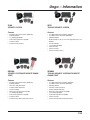
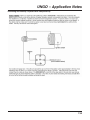
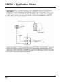
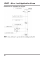
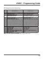
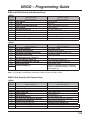
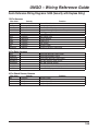
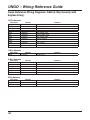
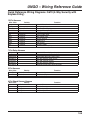
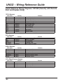
UNGO ProSecurity
121
Ungo – Information
K20
RK1
KEYLESS ENTRY SYSTEM
REMOTE ENGINE START WITH KEYLESS ENTRY
Features
Features
• (2) 4-Button Remote Transmitters (SAA474U)
•
•
•
•
•
•
•
•
•
•
•
• 2 Auxiliary Outputs
• On-Board Relays for Door Locks and Dome Light Supervision
• Horn Honk Output
• Driver’s Door Unlock Priority Compatible
• Comfort Closure
• (+/-) Parking Light Output
• Common Features
(2) 4-Button Remote Transmitters (SAA474U)
2 Auxiliary Outputs
Short Run / Turbo Timer Mode
Compact Satellite Relay Pack
Horn Honk Output
(+/-) Door Lock Outputs
Driver’s Door Unlock Priority Compatible
(+/-) Parking Light Output
ProSecurity Programmer Compatible
Common Features
Common Remote Start Features
RK210
RS10
2-WAY REMOTE START WITH KEYLESS ENTRY
SYSTEM
REMOTE ENGINE START WITH KEYLESS ENTRY
Features
•
•
•
•
•
•
•
•
•
•
•
•
(1) 2-Way LCD Remote Transmitter (SAA477U)
(1) 4-Button Remote Transmitter (SAA474U)
2 Auxiliary Outputs
Short Run / Turbo Timer Mode
Compact Satellite Relay Pack
Horn Honk Output
(+/-) Door Lock Outputs
Driver’s Door Unlock Priority Compatible
(+/-) Parking Light Output
ProSecurity Programmer Compatible
Common Features
Common Remote Start Features
123
Features
•
•
•
•
•
•
(1) 4-Button Remote Transmitter (SAA474U)
1 Auxiliary Output
(-) Door Lock Outputs
Short Run / Turbo Timer Mode
(+/-) Parking Light Output
Comfort Closure
Ungo – Information
S100
S670
SECURITY SYSTEM
TWO-WAY SECURITY SYSTEM
Features
Features
•
•
•
•
•
•
•
•
•
•
(2) 4-Button Remote Transmitters (SAA474U)
2 Auxiliary Outputs
(+/-) Parking Light Output
ProSecurity Programmer Compatible
Common Features
Common Security Features
•
•
•
•
•
(1) 2-Way LCD Remote Transmitter (SAA477U)
(1) 4-Button Remote Transmitter (SAA474U)
3 Auxiliary Outputs
On-Board Relays for Door Locks, Dome Light Supervision, and
Auxiliary 1
Horn Honk Output
(+/-) Parking Light Output
Comfort Closure
Common Features
Common Security Features
SR1000
SR6000
SECURITY SYSTEM WITH REMOTE ENGINE
START
TWO-WAY SECURITY SYSTEM WITH REMOTE
ENGINE START
Features
Features
•
•
•
•
•
•
•
•
•
•
•
•
•
•
•
•
•
•
•
•
(2) 4-Button Remote Transmitters (SAA474U)
3 Auxiliary Outputs
Short Run / Turbo Timer Mode
Compact Satellite Relay Pack
Horn Honk Output
Driver’s Door Unlock Priority Compatible
(+/-) Parking Light Output
ProSecurity Programmer Compatible
Common Features
Common Remote Start and Security Features
(1) 2-Way LCD Remote Transmitter (SAA477U)
(1) 4-Button Remote Transmitter (SAA474U)
3 Auxiliary Outputs
Short Run / Turbo Timer Mode
Compact Satellite Relay Pack
Driver’s Door Unlock Priority Compatible
(+/-) Parking Light Output
ProSecurity Programmer Compatible
Common Features
Common Remote Start and Security Features
124
UNGO – Features and Technologies
Common UNGO Features
Anti-Code Grabbing Technology
Individual Remote Recognition
Keyless Entry*
Remote Enabled Valet
Hyper Blue Status LED
Remote Panic
Selectable Ignition Controlled Door Locks
ProSecurity Starter Disable*
ProSecurity Power Up
Progressive Door Unlock*
Dome Light Supervision Output*
Trunk/Hatch Release Output*
UNGO Feature Descriptions
Anti-Carjacking
The optional anti-carjacking system feature is
designed to ensure that any unauthorized user of
the vehicle (even using the keys and remote control) will not be able to permanently separate the
owner from their vehicle.
This system cannot prevent a carjacking attempt;
however, it does ensure that if an unauthorized
user takes the vehicle, it will be disabled (after
several progressive warnings) as a safely as possible. * May Require Additional Parts & Labor
Common Security Features
Extended Range Antenna
Dual Stage Impact Sensor
Programmable Override Sequence
Remote Silent Arm/Disarm Capability
Event History Diagnostics
Selectable Siren Duration and Tones
False Alarm Prevention Circuitry
Common Remote Start Features
Extended Range Antenna
Anti-Grind Circuitry
Tachometer or Voltage Sensing
Gasoline or Diesel Vehicle Compatible
Over and Under Rev Protection
Built-in Wait-to-Start Timer
Selectable Run Timer
Short Run Timer / Turbo Timer Mode
Rear Defroster Activation
Anti-Code Grabbing Technology (a.k.a. Code
Hopping):
The receiver and remotes use a mathematical
formula called an algorithm to change their code
each time the remote is used. This technology
has been developed to increase the security of the
unit. The control unit knows what the next codes
should be. This helps to keep the remote “in sync”
with the control unit even if you use the remote
control out of range of the vehicle.
Anti-Grind Circuitry
Whenever the vehicle is remote started, advanced
anti-grind circuitry prevents the starter from engaging, even if the key is turned to the start position. This prevents damage to the starter motor if the
key is turned to the start position during remote
start operation.
Built-in Wait-to-Start Timer
Diesel vehicles need adequate time to warm up
the glow plugs prior to starting. When the remote
start is activated, the wait-to-start timer will allow
the glow plugs to properly warm up before engaging the starter circuit. This feature prevents damage to the motor and glow plugs during remote
start operation.
125
UNGO – Features and Technologies
Gasoline or Diesel Vehicle Compatible
Comfort Closure
If programmed ON the door lock output will activate the Comfort Closure output for 20 seconds. This output will begin 200mS after the final door
lock output has completed regardless of the door
lock programming. This feature is designed to
integrate with vehicle that can close the power
windows and sunroof by holding the key in the
driver door lock position, and will operate on both
single input systems and two pulse dead bolt
systems.
Dome Light Supervision Output
The dome light will illuminate for 30 seconds each
time the system is disarmed using the remote
control. This is useful for seeing inside the vehicle
at night prior to entering it.
Dual Stage Impact Sensor
A sensor mounted in the vehicle that is designed to
pick up impacts to the vehicle or glass. Depending
on the strength of the impact, the sensor can
determine whether it’s an accidental contact or
actual violation attempt.
ProSecurity remote start systems can be installed
into either gasoline or diesel vehicles. Hyper Blue LED
A blue LED (light Emmiting Diode) mounted at a
discretionary location inside the vehicle. It is used
to indicate the status of your system.
Individual Remote Recognition (IRR)
Individual Remote Recognition makes it possible
to program different settings for each remote that
is used with the system. Then, whenever a specific remote is used, the system will recall the setting assigned to that remote. IDR lets up to four
users of the system have different settings that
meet their specific needs. It is almost like having
four separate alarms in your vehicle, one for each
user.
Keyless Entry
Allows for easy entry or exiting of the vehicle without having fumbling around for keys. May require
additional parts and labor.
Over and Under Rev Protection
ProSecurity systems can provide notification that
the alarm was previously triggered. The status
LED will indicate which zone was involved. The
system will retain this information in its memory,
until the next time the ignition key is turned ON.
The system monitors the engine speed and will
automatically shut the engine off if the RPMs rise
above or fall below the programmed levels. This
feature prevents damage to the motor due to fuel
delivery system failures or other problems, which
may cause the engine to race.
Extended Range Antenna
Programmable Override Sequence
Event History Diagnostic
An optional external receiver/antenna used to
upgrade the remote/receiver performance in areas
of high radio interference such as military bases,
airports, and hospitals.
ProSecurity systems can be programmed to
respond to one to five pulses of the Valet/Override
Switch for the disarm function.
False Alarm Prevention
For added security, the ProSecurity system can
be configured to unlock the driver’s door only,
leaving the passenger doors locked. Pressing the
UNLOCK button an additional time will unlock the
passenger doors. This option requires additional
parts and labor.
It prevents annoying repetitive sequences due to
faulty door pins switches or environmental conditions such as thunder, jackhammers, airport
noise, etc.
Progressive Door Unlock
126
UNGO – Features and Technologies
ProSecurity Power Up
The ProSecurity system will store its current state
of non-volatile memory. If the power is lost and
then reconnected the system will recall the stored
state from memory. This means if the unit is in
Valet Mode and the battery is disconnected for
any reason, when the battery is reconnected the
unit will still be in Valet Mode. ProSecurity Starter Disable
An automatic switch controlled by your system
that prevents the vehicle’s starter from cranking
whenever the system is armed. The vehicle is
never prevented from cranking when the system is
disarmed, in Valet Mode, or if the starter interrupt
switch itself fails.
Rear Defroster Activation
During remote start operation, the rear defroster
can be activated. This option requires additional
parts and labor.
Remote Enabled Valet (REV)
The security system will not arm, even with
the remote, but all convenience functions (door
locks, trunk release, etc.) will still continue to
work normally. REV allows access to Valet Mode
without having to disclose the location of the Valet/
Override switch.
Remote Panic
If you are threatened in or near your vehicle, you
can attract attention by triggering the system with
your remote control. Just press the “PANIC” or
“LOCK” button for two seconds, and you will enter
Panic Mode. The siren will sound and the parking
lights will flash for the programmed siren duration. To stop Panic Mode at any time, press the “LOCK”
button on the remote.
Remote Silent Arm/Disarm Capability
The siren chirps upon arm or disarm can be
temporarily eliminated for that one operation only. The siren arm/disarm chirps can be turned off
permanently, if desired. The siren chirps will also
be eliminated during the warn-away trigger of the
127
Dual Stage Impact Sensor.
Selectable Ignition Controlled Door Locks
When the ignition is turned ON, the doors will
lock within 3 seconds and unlock when the ignition is turned OFF. Ignition controlled lock and
unlock are independent features are can be programmed separately.
Selectable Siren Duration and Tones
The duration of the siren can be programmed
to either 30 or 60 seconds. Some states have
laws regulating how long a security system
can sound. The multi-tone sirens included with
ProSecurity systems can be easily modified to
select desired tones or single tone.
Short Run Timer / Turbo Timer Mode
Short run turbo mode keeps the engine running
after arriving at your destination for a programmable period of time. Tachometer or Voltage Sensing
ProSecurity remote start systems either use a
tachometer signal or sense the voltage of the
vehicle during remote start activation. These
signals inform the remote start system that the
vehicle has successfully started and is running.
Trunk/Hatch Release Output
The system’s auxiliary output can be programmed to operate a factory power release for
the vehicle’s trunk or hatch. If the factory release
is not power activated, an optional trunk release
solenoid can often be added.
UNGO – Application Notes
Obtaining Optimal Range
Mounting the Extended Range Antenna:
1. Clean the mounting area with a quality glass
cleaner or alcohol to remove any dirt or residue.
2. Plug the receiver/antenna cable into the receiver/antenna.
3. Mount the receiver/antenna vertically using the
supplied double-sided tape.
4. Route the receiver/antenna cable to the control
module and plug it into the four-pin antenna connector.
Important:
• To achieve the best possible range, DO NOT leave
the antenna cable bundled up tightly underneath
the dash. Try to extend the cable the full length
during installation.
• DO NOT mount the control module to close the
vehicle’s Body Control Module and/or Electronic
Control Modules.
Mounting the Standard Antenna:
1. Route the antenna as high up as possible,
extending it to its full length.
2. Secure it in place using a cable tie.
Important:
• DO NOT cut or extend the antenna, as it’s tuned
precisely to the control unit.
• Route the antenna away from moving parts under
the dash and from the vehicle’s Body Control
Module and/or Electronic Control Modules.
Mounting the Control Unit:
• Do not mount or secure the control unit to close
to the vehicle’s Body Control Module and/or
Electronic Control Modules.
• Do not mount or secure the control unit to close
sources of heat, such as the heater core and/or
air ducts.
• Ground the control unit to a clean, paint-free
sheet metal location using a factory bolt that
DOES NOT have any vehicle component grounds
attached to it. A screw should only be used
when in conjunction with a two-sided lock washer. Under dash brackets and door sheet metal are not
acceptable ground points. It is recommended that all security components be
grounded at the same location.
Turning Off the Anti-Code Grabbing Technology
(a.k.a. Code Hopping):
Although this is a feature designed to prevent the
remote transmitters from being cloned and retransmitted to the control unit, it is virtual impossible to do. “Code Grabbers” have a very limited range, usually
required to within 5 feet of the remote transmitter
while the button is being depressed. By turning the
off the Anti-Code Grabbing feature, it can increase
the receiving/transmitting range by 30-35%. Refer to the “System Features Menu” for the Feature
Number and programming instructions.
Double Stacking (2) CR2016 Batteries:
The CR2032 3-volt micro lithium coin cell battery
inside of the SAA474U (4-button) remote transmitter
can be substituted with (2) CR2016 3-volt batteries. This can increase the range between 65-75%,
depending on the surroundings.
Procedure:
1. Insert a small flat head screwdriver into the notch
on the bottom of the remote transmitter.
2. Gently twist the screwdriver to spreading apart the
two halves of the remote transmitter.
3. Open up the remote transmitter exposing the
CR2032 battery and slide it out.
4. Slide (2) CR2016 batteries into the battery holder
with the “+” facing upwards. (It may be easier to
slide one battery in at a time. With the first battery
in place, slide the second battery between the PC
board and battery.)
5. Prior to closing the two halves of the remote
transmitter, verify the batteries are installed correctly
by pressing any of the buttons. The green LED
indicator should illuminate when a button is pressed. If the LED does not illuminate, double-check the
direction of the batteries. The “+” should be facing
upwards matching the “+” on the battery retaining
clip.
6. Snap together the two halves of the remote
transmitter.
128
UNGO – Application Notes
Obtaining a Tachometer
Reference Signal
The tachometer reference signal is an essential
signal for the safe operation of a remote start
system. This signal informs the remote start
module that the vehicle has successfully started
and is running. It can also determine whether the
vehicle is idling at a safe RPM level. In the event
the vehicles idle is racing or below safer operating
level, the remote start module will shut down.
To test for a tachometer wire, a multi-meter
capable of test AC voltage must be used. The
tachometer wire will show between 1V and 6V
AC. In multi-coil systems, the system can learn
individual coil wires. Individual coil wires in a multicoil ignition system will register lower amounts of
AC voltage. Also, if necessary, the system can
use a fuel injector control wire for engine speed
sensing. Common locations for a tachometer wire
are at the ignition coil, back of the gauge cluster,
engine computers, and automatic transmission
computers.
How to Find a Tachometer Wire with a MultiMeter:
1. Set the multi-meter to ACV or AC voltage (12V
or 20V is fine)
2. Attach the (-) probe of the meter to chassis
ground.
3. Start the vehicle and allow it to reach its normal
idle speed.
4. Probe the wire you suspect of being the tachometer wire with the red probe of the meter.
5. If it’s the correct wire the meter will read between
1V and 6V.
Multi-Coil Systems:
1. Examine the individual coils and determine
which wires are common on each coil. (Example:
2002 Chevy Pick-up: Each coil has 4 wires, three
common wires on each coil and the 4th wire
changes.)
2. The “different” colored wire can be used for the
tachometer reference signal for the remote start
module. (Only one coil wire is necessary.)
3. Teach tachometer reference signal to the remote
129
start module.
It is highly recommended to solder this connection, due to the heat generated inside the engine
bay. Using t-taps or scotch-locks are likely to fail
due to the heat.
Fuel Injector Wire:
1. Examine the individual fuel injectors and determine which wire(s) are common on each fuel
injector.
2. The “different” colored wire can be used for
the tachometer reference signal for the remote
start module. (Only one fuel injector wire is
necessary.)
3. Teach tachometer reference signal to the remote
start module.
It is highly recommended to solder this connection, due to the heat generated inside the engine
bay. Using t-taps or scotch-locks are likely to fail
due to the heat.
Tachometer Reference Options
Tachless
If programmed to the voltage sense setting, the
unit will crank the starter for a preset time during. Once the starter has been engaged, the system
will check the voltage level to verify the engine is
running.
When using tachless operation, it is essential to
determine the correct crank time to prevent damage to the starter. It may take several remote start
activations to determine the crank time.
Some vehicles have many accessories, which are
turned on during remote start activation. In these
vehicles, the variation of voltage between the
engine off and the vehicle running is very slight
and the remote start module may “think” the vehicle has not started. This can cause the remote
start module to shut down after the vehicle has
been started. If this is the case, the Voltage Check
Level must be set to the LOW position.
UNGO – Application Notes / Terms
Voltage sensing is not recommended in areas
that experience extreme cold temperatures. The
resistance in the vehicles wiring increases which
can cause intermittent remote start reliability.
454T: Alternator RPM Monitor
The 454T Alternator RPM Monitor is for use with
remote engine starts as an alternative to direct
connection to the vehicle’s tachometer or fuel
injector wire. It detects electrical spikes in the
vehicles electrical system and converts them into
an output that simulates a tachometer.
Passlock 2
The Passlock 2 system must see the correct
resistance code at the correct time. When the
ignition switch is turned to the crank position, the
“Bulb Check” wire is switched to ground. This
starts a time window during which the instrument
cluster panel (IPC) analyzes the resistance code
(R-Code). If the R-Code is valid and is received
in the proper window of time, the IPC sends a
code via data bus to the PCM to enable the fuel
injection system. If the key cylinder itself is pulled
out or damaged, it will not generate the resistance
code and the vehicle will not run.
Passkey 3
The Immobilizer uses an antenna ring around the
ignition cylinder to energize a small transponder
chip hidden in the ignition key. When the ignition is
turned on, the chip is energized and the antenna
rings sends the code to the Immobilizer control
unit. If the code is incorrect the vehicle will not
start. Remote Start Terms and
Definitions
Immobilizer (a.k.a.: Transponder)
The Immobilizer uses an antenna ring around the
ignition cylinder to energize a small transponder
chip hidden in the ignition key. When the ignition is
turned on, the chip is energized and the antenna
rings sends the code to the Immobilizer control
unit. The vehicle will only start if the code matches
the one programmed into the vehicle. Passkey/VATS
The Passkey/VATS system consists of four parts:
the Passkey cylinder, the ignition switch, the
instrument cluster panel (IPC), and the power train
control module (PCM). The system requires that
the key cylinder be mechanically turned using a
key. When the key cylinder is properly turned, it
generates a resistance code (R-Code), which is
sent to the IPC. The vehicle will only start if the
R-Codes match the key and key cylinder.
PATS
Passive Anti-Theft System (PATS) uses a specially
programmed key to start the vehicle, similar to the
Immobilizer. It uses an antenna ring around the
ignition cylinder to energize a small transponder
chip hidden in the ignition key. When the ignition is
turned on, the chip is energized and the antenna
ring sends the code to the PATS control unit. If the
code is incorrect the vehicle will not start.
Resistor
One of the components necessary in interface with
VATS factory anti-theft systems. A resistor(s) are
used in conjunction to reproduce the resistance
code (R-Code) embedded in the vehicle’s key
130
UNGO – Application Notes
131
UNGO – Application Notes
132
UNGO – Application Notes
133
UNGO – Application Notes
Interfacing with Passkey 3 systems with Relays and Key
134
UNGO – Application Notes
135
Ungo – Information
Bypass Modules
556U UNIVERSAL TRANSPONDER BYPASS MODULE
CHRYSLER
457CW DODGE, CHRYSLER JEEP DATA INTERFACE
555C CHRYSLER DODGE JEEP TRANSPONDER BYPASS
556C 2004-UP CHRYSLER DODGE JEEP TRANSPONDER
BYPASS
HONDA / ACURA
556H HONDA AND ACURA TRANSPONDER BYPASS MODULE
FORD
555P FORD PASSIVE ANTI-THEFT SYSTEM BYPASS MODULE
555S FORD SECURELOCK ANTI-THEFT SYSTEM BYPASS
MODULE
556S FORD SECURELOCK ANIT-THEFT BYPASS MODULE
GENERAL MOTORS
CAN2 2005-UP GENERAL MOTORS CAN BUS DATA
INTERFACE
457GW GM DATA BUS INTERFACE
555G GM PASSKEY III REMOTE START INTERFACE MODULE
555L DPASSLOCK BYPASS WITH LEARN ROUTINE
REMOTE CONTROLS
SAA474U 4-BUTTON TRANSMITTER
SAA477U TWO-WAY TRANSMITTER WITH ICONS
SENSORS
507M ELECTRONIC TILT AND MOTION SENSOR
508D INVISIBEAM FIELD DISTURBANCE SENSOR
504D DOUBLE GUARD SHOCK SENSOR
506T GLASS BREAKAGE SENSOR
GENERAL ACCESSORIES
451M DOOR LOCK RELAY ASSEMBLY
515R BACK-UP BATTERY SIREN
528T ADJUSTABLE TIMER RELAY
529T 2-WINDOW ROLL-UP KIT
530T 2-WINDOW AUTOMATION KIT
8632 SUPER BRIGHT RED LED WITH PLUG
SAA998T PROSECURITY PROGRAMMER
SAA988U SOFTWARE UPGRADE FOR PROSECURITY PROGRAMMER
TOYOTA / LEXUS
555X TOYOTA AND LEXUS TRANSPONDER BYPASS MODULE
VOLKSWAGEN
CAN1 VOLKSWAGEN CAN BUS INTERFACE
136
UNGO – Remote Start Diagnostics
Remote Start Diagnostics
In the event that a remote start system fails to start,
or stops running after a short period of time, you can
retrieve the source of the shutdown from the UNGO
ProSecurity system
1. Turn the Ignition off
2. Press and hold the Override switch
3. Turn the ignition on then off
4. Release the Override switch
5. Press and release the Override switch.
The LED will now report the last system shutdown
by flashing one of the following patterns for a period
of one minute.
LED Flashes
One Two Three Four Shutdown Cause
System Timed Out
Over-Rev Shutdown
Low or no RPM
Remote Shutdown or optional but-
ton
Six +/- Shutdown
Seven (-) Neutral Safety Shutdown
Eight Wait-to-Start Timed Out
Remote Start Troubleshooting
The ignition comes on, but the starter will not
crank
1. Does it start with the key in the ignition? If so, does
the vehicle have a VATS Pass-Key system?
2. Will it start with the brake pedal depressed? (Make
sure to disconnect the brake shutdown when performing this test.) If so, it may have a brake/starter
interlock.
3. Is the correct starter wire being energized? Check
by energizing it yourself with a fused test lead.
The starter cranks for six seconds but does not
start.
1. Either the wrong ignition wire is being energized,
the unit’s ignition and accessory wires have been
connected backwards, or the vehicle has two ignition
circuits. Try activating the unit with the ignition key in
the “run” position. If the vehicle then runs normally,
retest your ignition system.
137
The starter continues to crank even though
the engine has started.
1. Has the tach wire been learned? See Tach
Learning section of the installation guide.
2. Is the tach wire receiving the correct information? Either the wrong tach wire has been used,
or a bad connection exists.
The climate control system does not work
while the unit is operating the vehicle.
Either the wrong accessory wire is being energized or more than one ignition or accessory wire
must be energized in order to operate the climate
control system.
The remote start will not activate.
1. Check harnesses and connections. Make sure
the harnesses are fully plugged into the remote
start module. Make sure there are good connections to the vehicle wiring.
2. Check voltage and fuses. Use a meter and
check for voltage between the red wire in the 5 pin
ribbon harness and the black ground wire. If you
have less than battery voltage, check both 30A
fuses on the relay satellite. Also make sure that
the ground wire is going to a chassis ground and
not to something under the dash.
3. Check diagnostics. The diagnostics will tell you
which shutdown is active or not connected.
The remote start will activate but the starter
never engages.
1. Check for voltage on the purple starter wire two
seconds after the remote start becomes active. If
there is voltage present, skip to Step 4. If there is
not voltage present, advance to Step 2.
2. Check the 30A fuses.
3. Check diagnostics. If the gray/black wire is
detecting ground upon activation, the starter will
not crank.
4. Make sure the purple starter wire is connected
to the correct starter wire.
5. Does the vehicle have an immobilizer? Some
immobilizer systems will not allow the vehicle to
crank if active.
6. Check connections. The two red heavy gauge
input wires on the relay satellite should have solid
connections. “T-taps”, or “scotch locks” are not rec-
UNGO – Remote Start Diagnostics
ommended for any high current heavy gauge wiring.
Also, if the vehicle has more than one 12-volt input
wire, then connect one red wire to each.
The vehicle starts, but immediately dies
1. Does the vehicle have an immobilizer? The vehicles
immobilizer will cut the fuel and/or spark during unauthorized starting attempts.
2. Is the remote start programmed for voltage sense?
If so, the start time may not be set high enough,
or you may have to adjust the voltage threshold in
programming. Voltage sense will not work on some
vehicles.
3. Check diagnostics. Sometimes a shutdown will
become active during cranking or just after cranking.
The vehicle starts, but the starter keeps running
1. Is the system programmed for engine checking
off or voltage sense? When programmed for either
of these features, the engine cranks for the preprogrammed crank time regardless of how long it takes
to start the vehicle to actually start. Adjust to a lower
cranking time.
2. Was the Tach Learn successful? The LED must light
solidly and brightly to indicate a successful learn.
3. Make sure that there is a tach signal right at the
purple/white tach input wire of the remote start. If not,
recheck the connection to the vehicle’s tach wire and
make sure the wire is not broken or shorted to ground
leading to the remote start.
The vehicle will start and run only for about 10
seconds
1. Is the remote start programmed for voltage sense?
Try programming the unit for low voltage reference. If
this does not work, a tach wire should be used.
2. Check diagnostics.
138
UNGO – Multiple Vehicle Operation
Technical Information: Multiple Vehicle Operation
Ungo ProSecurity remote transmitters are capable of operating multiple vehicles equipped with ProSecurity
systems. This is beneficial for individuals with multiple vehicles and/or reducing the clutter on a keychain. 1. Follow the remote programming procedure for the particular ProSecurity system and delete all the
remote transmitters for both vehicles.
2. Follow the remote programming procedure for the particular ProSecurity system and program the
desired function to the assigned button. Continue this process until all the button assignments have been
complete on both vehicles.
EXAMPLE: S100 Multiple Vehicle Operation
Programming Vehicle 1.
1. Open the door of the Vehicle 1.
2. Turn the ignition ON
3. Press the Valet/Override button 9 times and then press it one more time and hold it in. The LED
will flash 9 times indicating that selection.
4. Release the Valet/Override button and turn the ignition OFF and then back ON.
5. Press the Valet/Override button 4 times and then press it one more time and hold it in.
6. Press the LOCK button on each remote transmitter. The LED will flash 4 times indicating that
selection.
7. Release the Valet/Override button and press it 1 time and then hold it in. The LED will flash 5
times indicating that selection.
8. Press the UNLOCK button on each remote transmitter. The LED will flash 5 times indicating that
selection.
9. Release the Valet/Override button and turn the ignition OFF and then back ON.
10.Turn the ignition ON.
11.Press the Valet/Override button 2 times and then press it one more time and hold it in. 12.Press both the LOCK and UNLOCK buttons together on each remote transmitter. The LED will
flash 2 times indicating that selection.
13.Release the Valet/Override button and turn the ignition OFF.
139
UNGO – Multiple Vehicle Operation
Vehicle 1:
LOCK: Arm (Lock)
UNLOCK: Disarm (Unlock)
LOCK & UNLOCK: Channel 2 (Auxiliary 1)
Programming Vehicle 2
1. Open the door of the Vehicle 2.
2. Turn the ignition ON
3. Press the Valet/Override button 9 times and then press it one more time and hold it in. The LED will flash 9 times indicating that selection.
4. Release the Valet/Override button and turn the ignition OFF and then back ON.
5. Press the Valet/Override button 4 times and then press it one more time and hold it in.
6. Press the AUX button on each remote transmitter. The LED will flash 4 times indicating
that selection.
7. Release the Valet/Override button and press it 1 time and then hold it in. The LED will
flash 5 times indicating that selection.
8. Press the “*” button on each remote transmitter. The LED will flash 5 times indicating that
selection.
9. Release the Valet/Override button and turn the ignition OFF and then back ON.
10.Turn the ignition ON.
11.Press the Valet/Override button 2 times and then press it one more time and hold it in. 12.Press both the AUX and “*” buttons together on each remote transmitter. The LED will
flash 2 times indicating that selection.
13.Release the Valet/Override button and turn the ignition OFF.
Vehicle 2:
AUX: Arm (Lock)
“*”: Disarm (Unlock)
AUX and “*”: Channel 2 (Auxiliary 1)
140
UNGO – Door Lock Application Guide
Reverse Polarity Door Lock Systems
Aftermarket Door Lock Actuators
141
UNGO – Door Lock Application Guide
Vacuum Door Lock Systems
The lock pulse duration my be programmed to 3.5 seconds
One-Wire Door Lock System
This door lock system requires a negative pulse to unlock the foors , and cutting the wire to lock the
doors.
142
UNGO – Door Lock Application Guide
Multiplexed Door Lock Systems
Multiplexed door lock systems have more than one function on the same wire and require the use of different resistor values. It is necessary to use external relays any time a resistor is used.
Positive Trigger Multiplexed Door Lock System
Test Procedure for Multiplexed Door Lock Systems:
1.
Locate the Lock/Unlock wire in the vehicle.
2.
Cut the wire in half and determine the polarity of the wire.
3.
Using a digital multimeter, measure the resistance for Lock and Unlock. (See Diagram)
Test Configuration for Positive Door Lock Systems
143
UNGO – Door Lock Application Guide
Multiplexed Door Lock Systems
Multiplexed door lock systems have more than one function on the same wire and require the use of different resistor values. It is necessary to use external relays any time a resistor is used.
Negative Trigger Multiplexed Door Lock System
Test Procedure for Multiplexed Door Lock Systems:
1.
Locate the Lock/Unlock wire in the vehicle.
2.
Cut the wire in half and determine the polarity of the wire.
3.
Using a digital multimeter, measure the resistance for Lock and Unlock. (See Diagram)
Test Configuration for Positive Door Lock Systems
144
UNGO – Door Lock Application Guide
Multiplexed Door Lock Systems with On-Board Relays
Reverse Polarity Door Lock Systems with On-Board Relays:
145
UNGO – Door Lock Application Guide
Progressive Door Lock Using Positive Door Lock Trigger
146
UNGO – Door Lock Application Guide
Progressive Door Lock Using Negative Door Lock Trigger
147
UNGO – Programming Guide
Technical Information Module Programming: Models: K10, K20, S670, RS10
System features can also be changed by using the ProSecurity Programmer
148
UNGO – Programming Guide
K10 (Keyless Entry)
Feature
Default LED ON
Number
(Press Channel 1)
1
Active Arming
2
Chirps ON
3
Ignition Control Door Lock ON
4
Ignition Control Door Unlock ON
5
Active Locking
6
Ignition Control Dome Light ON
7
0.8 Second Door Lock Pulse
8
Double Pulse Unlock OFF
9
Security Features ON
10
Code Hopping ON
Note: Factory default settings are shown BOLD.
LED OFF Setting
(Press Channel 2)
Passive Arming
Chirps OFF
Ignition Control Door Lock OFF
Ignition Control Door Unlock OFF
Passive Locking
Ignition Control Dome Light OFF
3.5 Second Door Lock Pulse
Double Pulse Unlock ON
Security Features OFF
Code Hopping OFF
K20 (Keyless Entry with On-Board Relays)
Feature
Default LED ON
LED OFF Setting
Number
(Press Channel 1)
(Press Channel 2)
1
Ignition Control Door Lock ON
Ignition Control Door Lock OFF
2
Ignition Control Door Unlock ON
Ignition Control Door Unlock OFF
3
Ignition Control Dome Light ON
Ignition Control Dome Light OFF
4
0.8 Second Door Lock Pulse
3.5 Second Door Lock Pulse / 0.4 sec.
5
Double Pulse Unlock OFF
Double Pulse Unlock ON
6
Double Pulse Lock OFF
Double Pulse Lock ON
7
Comfort Closure OFF
Comfort Closure ON
8
Code Hopping ON
Code Hopping OFF
Note: Factory default settings are shown BOLD.
Note: For feature 1-4, the 3.5 second door lock pulse setting the siren (or horn)
chirps twice, for the 0.4 second door lock pulse setting for the siren (or horn) chirps three times
S670 (2-Way Security with Keyless Entry)
Feature
Default LED ON
Number
(Press Channel 1)
1-1
Active Arming
1-2
Chirps ON
1-3
Ignition Control Door Locks ON
1-4
Active Locking
1-5
Door Lock Pulse Duration 0.8 Seconds
1-6
Single Unlock Pulse
1-7
Anti-Code Grabbing ON
1-8
Open Zone Bypass Notice ON
1-9
Single Unlock Pulse
1-10 Comfort Closure ON
Note: Factory default settings are shown BOLD.
149
LED OFF Setting
(Press Channel 2)
Passive Arming
Chirps OFF
Ignition Control Door Locks OFF
Passive Locking
Door Lock Pulse Duration 3.5 Seconds
Double Unlock Pulse
Anti-Code Grabbing OFF
Open Zone Bypass Notice OFF
Double Unlock Pulse
OFF
UNGO – Programming Guide
RS10 (Remote Start with Keyless Entry)
Feature
Default LED ON
Number
(Press Channel 1)
1
Engine Check ON
2
Tachometer Sensing
3
12 Minute Run Time (1)*
4
Flashing Parking Light Output
5
Cranking Time 0.6 Sec. (1)*
6
Voltage Check Level High
7
Short Run (Turbo Timer): 1 Min. (1)*
8
Activation Pulse: 1 (1)*
9
Ignition/Accessory Output: Ignition
10
Accessory State During Wait to Start: OFF
11
2nd Status Output: Normal (1)*
12
Diesel Time Wait-to-Start Input (1)*
13
Run Time (Timer Mode) 12 Minutes (1)*
14
Door Lock Pulse Duration 0.8 Sec. (1)*
15
Unlock Output 1 Pulse
16
Lock Output 1 Pulse
17
Ignition Unlock ON
18
Ignition Lock ON
19
Factory Alarm Disarm Function with Unlock
20
Factory Alarm Disarm 1 Pulse
21
Comfort Closure ON
Note: Factory default settings are shown BOLD.
Note: * The number in parentheses indicate the number of
LED OFF Setting
(Press Channel 2)
Engine Checking OFF
Voltage Sensing
24 Min (2)*, 60 Min Run Time (3)*
Constant Parking Light Output
Crank Time 0.8 (2)*, 1.0 (3)*, 1.2 (4)*, 1.4 (5)*,
1.6 (6)*, 1.8 (7)*, 2.0 (8)*, 4.0 (9)*
Voltage Check Level Low
Short Run (Turbo Timer): 3 (2)*, 5 (3)*, 10 (4)*
Activation Pulses: 2 (2)*, 3 (3)*
Ignition/Accessory Output: Accessory
Accessory State During Wait to Start: ON
Rear Defogger Latched (2)*, Pulsed (3)*
Timed 15 (2)*, 30 (3)*, 45 (4)* Seconds
3 (2)*, 6 (3)*, 9 (4)* Minutes
3.5 (2)*, 0.4 (3)* Seconds
Unlock Output 2 Pulses
Lock Output 2 Pulses
Ignition Unlock OFF
Ignition Lock ON
Before Lock (2)*, Remote Start Only (3)*
2 Pulse
OFF
times the LED will flash.
150
UNGO – Programming Guide
Technical Information Module Programming: Models: S100, S400, S660, SR1000, SR5000, SR6000
System features can also be changed by using the ProSecurity Programmer
151
UNGO – Programming Guide
S100 and S400 (Security with Keyless Entry)
MENU 1
Feature
Number
1-1
1-2
1-3
1-4
1-5
1-6
1-7
1-8
1-9
1-10
Default LED ON
(Press Channel 1)
Active Arming
Chirps ON
Ignition Control Door Locks ON
Active Locking
Panic with Ignition ON
Door Lock Pulse Duration 0.8 Seconds
Forced Passive Arming ON
Automatic Engine Disable ON
Armed When Driving
Anti-Code Grabbing ON
LED OFF Setting
(Press Channel 2)
Passive Arming
Chirps OFF
Ignition Control Door Locks OFF
Passive Locking
Panic with Ignition OFF
Door Lock Pulse Duration 3.5 Seconds
Forced Passive Arming OFF
Automatic Engine Disable OFF
Anti-Carjacking System
Anti-Code Grabbing OFF
MENU 2
Feature
Number
2-1
2-2
2-3
2-4
Default LED ON
(Press Channel 1)
Siren Output Constant
30-Second Siren Duration
False Alarm Prevention Circuitry ON
Progressive Door Trigger
LED OFF Setting
(Press Channel 2)
Siren Output Pulsed
60-Second Siren Duration
False Alarm Prevention Circuitry OFF
Instant Door Trigger
Override Switch Input: 2 (2)*, 3 (3)*, 4 (4)*, 5
(5)*
Open Zone Bypass Notice OFF
Ignition Controlled Dome Light OFF
Double Unlock Pulse
Channel 3: Latched/Latched (2)*, Reset with
Ignition (3)*, 30-Second Timed (4)*, Second
Unlock Output (5)*
2-5
Override Switch Input: 1 Pulse (1)*
2-6
Open Zone Bypass Notice ON
2-7
Ignition Controlled Dome Light ON
2-8
Single Unlock Pulse
2-9
Channel 3: Validity (1)*
Note: Factory default settings are shown BOLD.
Note: * The number in parentheses indicate the number of times the LED will flash.
S660 (2-Way Security with Keyless Entry)
MENU 1
Feature
Number
1-1
1-2
1-3
1-4
1-5
1-6
1-7
1-8
1-9
1-10
1-11
Default LED ON
(Press Channel 1)
Active Arming
Chirps ON
Ignition Control Door Locks ON
Ignition Unlock ON
Active Locking
Panic with Ignition ON
Door Lock Pulse Duration 0.8 Seconds
Forced Passive Arming ON
Automatic Engine Disable ON
Armed When Driving ON
Anti-Code Grabbing ON
LED OFF Setting
(Press Channel 2)
Passive Arming
Chirps OFF
Ignition Control Door Locks OFF
Ignition Unlock OFF
Passive Locking
Panic with Ignition OFF
Door Lock Pulse Duration 3.5 Seconds
Forced Passive Arming OFF
Automatic Engine Disable OFF
Armed When Driving OFF
Anti-Code Grabbing OFF
152
UNGO – Programming Guide
MENU 2
Feature
Number
2-1
2-2
2-3
2-4
Default LED ON
(Press Channel 1)
Siren Output Constant
30-Second Siren Duration
False Alarm Prevention Circuitry ON
Progressive Door Trigger
LED OFF Setting
(Press Channel 2)
Siren Output Pulsed
60-Second Siren Duration
False Alarm Prevention Circuitry OFF
Instant Door Trigger
Override Switch Input: 2 (2)*, 3 (3)*, 4 (4)*, 5
(5)*
Open Zone Bypass Notice OFF
Ignition Controlled Dome Light OFF
Double Unlock Pulse
FAD with Channel 2 OFF
Channel 4: Latched/Latched (2)*, Reset with
Ignition (3)*, 30-Second Timed (4)*, 60-Second
Timed (5)*, 90-Second Timed (6)*
Channel 5: Latched/Latched (2)*, Reset with
Ignition (3)*, 30-Second Timed (4)*, 60-Second
Timed (5)*, 90-Second Timed (6)*
2-5
Override Switch Input: 1 Pulse (1)*
2-6
Open Zone Bypass Notice ON
2-7
Ignition Controlled Dome Light ON
2-8
Single Unlock Pulse
2-9
FAD with Channel 2 ON
2-10
Channel 4: Validity (1)*
2-11
Channel 5: Validity (1)*
Note: Factory default settings are shown BOLD.
Note: * The number in parentheses indicate the number of times the LED will flash.
SR1000 (Remote Start with Security Combo)
MENU 1
Feature
Number
1-1
1-2
1-3
1-4
1-5
1-6
1-7
1-8
1-9
1-10
1-11
153
Default LED ON
(Press Channel 1)
Active Arming
Chirps ON
Ignition Control Door Locks ON
Ignition Unlock ON
Active Locking
Panic with Ignition ON
Door Lock Pulse Duration 0.8 Seconds
Forced Passive Arming ON
Automatic Engine Disable ON
Armed When Driving ON
Anti-Code Grabbing ON
LED OFF Setting
(Press Channel 2)
Passive Arming
Chirps OFF
Ignition Control Door Locks OFF
Ignition Unlock OFF
Passive Locking
Panic with Ignition OFF
Door Lock Pulse Duration 3.5 Seconds
Forced Passive Arming OFF
Automatic Engine Disable OFF
Armed When Driving OFF
Anti-Code Grabbing OFF
UNGO – Programming Guide
MENU 2
Feature
Number
2-1
2-2
2-3
2-4
2-5
2-6
2-7
2-8
2-9
2-10
2-11
MENU 3
Feature
Number
3-1
3-2
3-3
3-4
3-5
3-6
3-7
3-8
3-9
3-10
3-11
3-12
Default LED ON
(Press Channel 1)
Siren Output Constant
30-Second Siren Duration
False Alarm Prevention Circuitry ON
Progressive Door Trigger
Override Switch Input: 1 Pulse (1)*
Open Zone Bypass Notice ON
Ignition Controlled Dome Light ON
Single Unlock Pulse
FAD with Channel 2 ON
Channel 4: Validity (1)*
Channel 5: Validity (1)*
LED OFF Setting
(Press Channel 2)
Siren Output Pulsed
60-Second Siren Duration
False Alarm Prevention Circuitry OFF
Instant Door Trigger
Override Switch Input: 2 (2)*, 3 (3)*, 4 (4)*, 5
(5)*
Open Zone Bypass Notice OFF
Ignition Controlled Dome Light OFF
Double Unlock Pulse
FAD with Channel 2 OFF
Channel 4: Latched/Latched (2)*, Reset with
Ignition (3)*, 30-Second Timed (4)*, 60-Second
Timed (5)*, 90-Second Timed (6)*
Channel 5: Latched/Latched (2)*, Reset with
Ignition (3)*, 30-Second Timed (4)*, 60-Second
Timed (5)*, 90-Second Timed (6)*
Default LED ON
(Press Channel 1)
Engine Check ON
Tachometer Sensing
12 Minute Run Time (1)*
Flashing Parking Light Output
Cranking Time 0.6 Sec. (1)*
Voltage Check Level High
Short Run (Turbo Timer): 1 Min. (1)*
Activation Pulse: 1 (1)*
2nd Ignition Output
Accessory State During Wait to Start: OFF
2nd Status Output: Normal (1)*
Anti-Grind ON
LED OFF Setting
(Press Channel 2)
Engine Checking OFF
Voltage Sensing
24 Min (2)*, 60 Min Run Time (3)*
Constant Parking Light Output
Crank Time 0.8 (2)*, 1.0 (3)*, 1.2 (4)*, 1.4 (5)*,
1.6 (6)*, 1.8 (7)*, 2.0 (8)*, 4.0 (9)*
Voltage Check Level Low
Short Run (Turbo Timer): 3 (2)*, 5 (3)*, 10 (4)*
Activation Pulses: 2 (2)*, 3 (3)*
2nd Accessory Output
Accessory State During Wait to Start: ON
Rear Defogger Latched (2)*, Pulsed (3)*
Anti-Grind OFF
154
UNGO – Programming Guide
Note: Factory default settings are shown BOLD.
Note: * The number in parentheses indicate the number of times the LED will flash.
SR5000 (2-Way Remote Start with Security Combo)
MENU 1
Feature
Default LED ON
Number
(Press Channel 1)
1-1 Active Arming
1-2 Chirps ON
1-3 Ignition Control Door Locks ON
1-4 Active Locking
1-5 Panic with Ignition ON
1-6 Door Lock Pulse Duration 0.8 Seconds
1-7 Forced Passive Arming ON
1-8 Automatic Engine Disable ON
1-9 Armed When Driving
1-10 Anti-Code Grabbing ON
Passive Arming
Chirps OFF
Ignition Control Door Locks OFF
Passive Locking
Panic with Ignition OFF
Door Lock Pulse Duration 3.5 Seconds
Forced Passive Arming OFF
Automatic Engine Disable OFF
Anti-Carjacking System
Anti-Code Grabbing OFF
MENU 2
Feature
Default LED ON
Number
(Press Channel 1)
2-1 Siren Output Constant
2-2 30-Second Siren Duration
2-3 False Alarm Prevention Circuitry ON
2-4 Progressive Door Trigger
2-5 Override Switch Input: 1 Pulse (1)*
2-6 Open Zone Bypass Notice ON
2-7 Ignition Controlled Dome Light ON
2-8 Single Unlock Pulse
2-9 FAD with Channel 2 ON
2-10 Channel 4: Validity (1)*
LED OFF Setting
(Press Channel 2)
Siren Output Pulsed
60-Second Siren Duration
False Alarm Prevention Circuitry OFF
Instant Door Trigger
Override Switch Input: 2 (2)*, 3 (3)*, 4 (4)*, 5 (5)*
Open Zone Bypass Notice OFF
Ignition Controlled Dome Light OFF
Double Unlock Pulse
FAD with Channel 2 OFF
Channel 4: Latched/Latched (2)*, Reset with
Ignition (3)*, 30-Second Timed (4)*, 60-Second
Timed (5)*, 90-Second Timed (6)*
MENU 3
Feature
Default LED ON
Number
(Press Channel 1)
3-1 Engine Check ON
3-2 Tachometer Sensing
3-3 12 Minute Run Time (1)*
3-4 Flashing Parking Light Output
3-5 Cranking Time 0.6 Sec. (1)*
3-6 Voltage Check Level High
3-7 Auxiliary Output: Factory Alarm Disarm
3-8 Status Output
LED OFF Setting
(Press Channel 2)
Engine Checking OFF
Voltage Sensing
24 Min (2)*, 60 Min Run Time (3)*
Constant Parking Light Output
Crank Time 0.8 (2)*, 1.0 (3)*, 1.2 (4)*, 1.4 (5)*,
1.6 (6)*, 1.8 (7)*, 2.0 (8)*, 4.0 (9)*
Voltage Check Level Low
Special Accessory
Factory Alarm Rearm
155
LED OFF Setting
(Press Channel 2)
UNGO – Programming Guide
3-9 Anti-Grind ON
Anti-Grind OFF
Note: Factory default settings are shown BOLD.
Note: * The number in parentheses indicate the number of times the LED will flash.
SR6000 (2-Way Remote Start with Security Combo)
MENU 1
Feature
Default LED ON
Number
(Press Channel 1)
1-1 Active Mode
1-2 Chirps ON
1-3 Ignition Lock ON
1-4 Ignition Unlock ON
1-5 Active Locking
1-6 Panic with Ignition ON
1-7 Door Lock Pulse Duration 0.8 Seconds
1-8 Forced Passive Arming ON
1-9 Automatic Engine Disable ON
1-10 Armed When Driving
1-11 Anti-Code Grabbing ON
Passive Mode
Chirps OFF
Ignition Lock OFF
Ignition Unlock OFF
Passive Locking
Panic with Ignition OFF
Door Lock Pulse Duration 3.5 Seconds
Forced Passive Arming OFF
Automatic Engine Disable OFF
Anti-Carjacking System
Anti-Code Grabbing OFF
MENU 2
Feature
Default LED ON
Number
(Press Channel 1)
2-1 Siren Output Constant
2-2 30-Second Siren Duration
2-3 False Alarm Prevention Circuitry ON
2-4 Progressive Door Trigger
2-5 Override Switch Input: 1 Pulse (1)*
2-6 Open Zone Bypass Notice ON
2-7 Ignition Controlled Dome Light ON
2-8 Single Unlock Pulse
2-9 FAD with Channel 2 ON
2-10 Channel 4: Validity (1)*
LED OFF Setting
(Press Channel 2)
Siren Output Pulsed
60-Second Siren Duration
False Alarm Prevention Circuitry OFF
Instant Door Trigger
Override Switch Input: 2 (2)*, 3 (3)*, 4 (4)*, 5 (5)*
Open Zone Bypass Notice OFF
Ignition Controlled Dome Light OFF
Double Unlock Pulse
FAD with Channel 2 OFF
Channel 4: Latched/Latched (2)*, Reset with
Ignition (3)*, 30-Second Timed (4)*, 60-Second
Timed (5)*, 90-Second Timed (6)*
LED OFF Setting
(Press Channel 2)
156
UNGO – Remote Programming
2-11
Channel 5: Validity (1)*
Channel 5: Latched/Latched (2)*, Reset with
Ignition (3)*, 30-Second Timed (4)*, 60-Second
Timed (5)*, 90-Second Timed (6)*
MENU 3
Feature
Default LED ON
LED OFF Setting
Number
(Press Channel 1)
(Press Channel 2)
3-1 Engine Check ON
Engine Checking OFF
3-2 Tachometer Sensing
Voltage Sensing
3-3 12 Minute Run Time (1)*
24 Min (2)*, 60 Min Run Time (3)*
3-4 Flashing Parking Light Output
Constant Parking Light Output
3-5 Cranking Time 0.6 Sec. (1)*
Crank Time 0.8 (2)*, 1.0 (3)*, 1.2 (4)*, 1.4 (5)*,
1.6 (6)*, 1.8 (7)*, 2.0 (8)*, 4.0 (9)*
3-6 Voltage Check Level High
Voltage Check Level Low
3-7 Short Run (Turbo Timer): 1 Min. (1)*
Short Run (Turbo Timer): 3 (2)*, 5 (3)*, 10 (4)*
3-8 Activation Pulse: 1 (1)*
Activation Pulses: 2 (2)*, 3 (3)*
3-9 2nd Ignition Output
2nd Accessory Output
3-10 Accessory State During Wait to Start: OFF Accessory State During Wait to Start: ON
3-11 2nd Status Output: Normal (1)*
Rear Defogger Latched (2)*, Pulsed (3)*
3-12 Anti-Grind ON
Anti-Grind OFF
Note: Factory default settings are shown BOLD.
Note: * The number in parentheses indicate the number of times the LED will flash.
RK1 (Advanced Remote Start with Keyless Entry)
MENU 1
Feature
Default LED ON
Number
(Press Channel 1)
1-1 Active Mode
1-2 Chirps ON
1-3 Ignition Lock ON
1-4 Ignition Unlock ON
1-5 Active Locking
1-6 Panic with Ignition ON
1-7 Door Lock Pulse Duration 0.8 Seconds
1-8 Double Unlock Pulse OFF
1-9 Channel 2 Delayed Validity (1)*
1-10 FAD with Channel 2 ON
1-11 Security Features ON
157
LED OFF Setting
(Press Channel 2)
Passive Mode
Chirps OFF
Ignition Lock OFF
Ignition Unlock OFF
Passive Locking
Panic with Ignition OFF
Door Lock Pulse Duration 3.5 Seconds
Double Unlock Pulse ON
Channel 2 Latched (2)*, Latched Reset with
Ignition (3)*, 30 Second Timed (4)*
FAD with Channel 2 OFF
Security Features OFF (Starter Kill)
UNGO – Remote Programming
1-12
1-13
Code Hopping ON
Channel 4 Validity (1)*
MENU 2
Feature
Default LED ON
Number
(Press Channel 1)
2-1 Engine Check ON
2-2 Tachometer Sensing
2-3 12 Minute Run Time (1)*
2-4 Flashing Parking Light Output
2-5 Cranking Time 0.6 Sec. (1)*
2-6 Voltage Check Level High
2-7 Short Run (Turbo Timer): 1 Min. (1)*
2-8 Activation Pulse: 1 (1)*
2-9 2nd Ignition Output
2-10 Accessory State During Wait to Start: OFF
2-11 2nd Status Output: Normal (1)*
2-12 Anti-Grind ON
Note: Factory default settings are shown BOLD.
Note: * The number in parentheses indicate the number
Code Hopping OFF
Latched (2)*, Latched Reset with Ignition (3)*,
30-Second Timed (4)*
LED OFF Setting
(Press Channel 2)
Engine Checking OFF
Voltage Sensing
24 Min (2)*, 60 Min Run Time (3)*
Constant Parking Light Output
Crank Time 0.8 (2)*, 1.0 (3)*, 1.2 (4)*, 1.4 (5)*,
1.6 (6)*, 1.8 (7)*, 2.0 (8)*, 4.0 (9)*
Voltage Check Level Low
Short Run (Turbo Timer): 3 (2)*, 5 (3)*, 10 (4)*
Activation Pulses: 2 (2)*, 3 (3)*
2nd Accessory Output
Accessory State During Wait to Start: ON
Rear Defogger Latched (2)*, Pulsed (3)*
Anti-Grind OFF
of times the LED will flash.
Remote Programming
158
UNGO – Remote Programming
K10, S100, S400
Channel
Number
1
2
3
4
5
6
7
8
9
Function
Arm/Disarm/Panic
Silent Mode / Channel 2 Output
Channel 3 Output
Arm Only
Disarm Only
Panic Only
Auto-Learn Single Button Arm/Disarm Configuration
Auto-Learn Standard Configuration
Delete All Remotes
Wire Color
Red/White
White/Blue
K20
Channel
Number
1
2
3
4
5
6
7
8
Function
Auto-Learn Standard Configuration
Arm Only
Disarm Only
Silent Mode / Channel 2 Output
Channel 3 Output
Arm/Disarm/Panic
Panic Only
Delete All Remotes
Wire Color
Red/White
White/Blue
RS10
Channel
Number
159
Function
Wire Color
UNGO – Remote Programming
1
2
3
4
5
6
7
8
Auto-Learn
Lock/Unlock
Channel 2 Output
Remote Start
Turbo Timer / Short Run
Turbo Timer / Short Run
Rear Window Defogger Control
Delete All Remotes
Red/White
S660
Channel
Number
1
2
3
4
5
6
7
8
9
10
11
12
Function
Auto-Learn Standard Configuration
Arm Only
Disarm Only
Silent Mode / Channel 2 Output
No Function
Channel 4
Channel 5
No Function
No Function
Arm/Disarm/Panic
Panic Only
Delete All Remotes
Wire Color
Red/White
Violet/Black
White/Black
S670
Channel
Number
1
2
3
4
5
6
7
8
9
10
Function
Arm/Disarm/Panic
Silent Mode / Channel 2 Output
Channel 3
Channel 4
Arm Only
Disarm Only
Panic Only
Auto-Learn (4-Button and LCD 2-Way Remotes)
Auto-Learn (3 Button Optional Remotes)
Delete All Remotes
Wire Color
Red/White
White/Blue
Violet/Black
SR1000, SR6000
Channel
Number
1
2
3
4
Function
Auto-Learn Standard Configuration
Arm Only
Disarm Only
Silent Mode / Channel 2 Output
Wire Color
Red/White
160
UNGO – Wiring Reference Guide
5
6
7
8
9
10
11
12
Remote Start
Channel 4
Channel 5
Turbo Timer / Short Run
Timer Mode
Arm/Disarm/Panic
Panic Only
Delete All Remotes
Violet/Black
White/Black
SR5000
Channel
Number
1
2
3
4
5
6
7
8
9
10
Function
Arm/Disarm/Panic
Silent Mode / Channel 2 Output
Remote Start
Channel 4
Arm Only
Disarm Only
Panic Only
Auto-Learn Standard Configuration
Auto-Learn Single Button Arm/Disarm Configuration
Delete All Remotes
Wire Color
Red/White
Violet/Black
RK1
Channel
Number
1
2
3
4
5
6
7
8
9
10
11
161
Function
Auto-Learn Standard Configuration
Arm Only
Disarm Only
Silent Mode / Channel 2 Output
Remote Start
Channel 4
Turbo Timer / Short Run
Timer Mode
Arm/Disarm/Panic
Panic Only
Delete All Remotes
Wire Color
Red/White
Violet/Black
UNGO – Wiring Reference Guide
Quick Reference Wiring Diagrams: K10 (Keyless Entry)
12-Pin Harness
Wire Color
Orange
White
White/Blue
Black/White
Green
Blue
Violet
Black
Yellow
Brown
Red
Red/White
Polarity
(-) 500mA
(-) 200mA
(-) 200mA
(-) 200mA
(-) Negative
(-) Negative
(+) Positive
(-) 200mA
(+) Positive
(-) 200mA
Function
Ground When Armed
Parking Light Output
Channel 3 Auxiliary Output
Dome Light Supervision Output
Not Used
Second Unlock Output
Not Used
Chassis Ground
Ignition Input
Horn Output
Constant Power
Channel 2 Auxiliary Output
3-Pin Harness
Wire Color
Green
Empty
Blue
Polarity
(-) Lock, (+) Unlock
(-) Unlock, (+) Lock
Function
(-) Lock, (+) Unlock
(-) Unlock, (+) Lock
Quick Reference Wiring Diagrams: K20 (Keyless Entry with On-Board Relays)
18-Pin Harness
Wire Color
Violet
Red/White
Blue/Black
Brown/Black
Violet/Black
Orange
White/Black
Yellow
Green/Black
White/Blue
Black/White
LT. Green/Black
Black/White-1
Brown
Blue
Black
Red
White
Polarity
(-) 200mA
(-) 500mA
(+) Positive
(-) 200mA
(-) 200mA
(-) 200mA
(-) Negative
(-) Negative
(+) Positive
(+) 10 amp /
Function
Unlock #87 Normally Open (Input)
Channel 2 Auxiliary Output
Unlock #30 Common Output
Unlock #87A Normally Open (Input)
Lock #87 Normally Open (Input)
Ground When Armed
Lock #87 Normally Closed
Ignition Input
Lock #30 Common Output
Channel 3 Auxiliary Output
Output of Domelight Supervision Relay #87
Factory Alarm Disarm
Input of Domelight Supervision Relay #30
Horn Output
Second Unlock Output
Chassis Ground
Constant Power
(-) 200mA Parking Light Output
162
UNGO – Wiring Reference Guide
Quick Reference Wiring Diagrams: RS10 (Remote Start with
Keyless Entry)
5-Pin Harness
Wire Color
Blue/White
Gray
Brown
Violet/White
Black/White
Polarity
(-) 200mA
(-) Negative
(+) Positive
(-) Negative
Function
2nd Status Output / Rear Defroster
Hood Pin Shutdown
Brake Shutdown
Tachometer Input
Neutral Safety Shutdown
9-Pin Harness
Wire Color
White
Black
Red/White
White/Red
Gray/Black
White/Blue
Yellow
Green/White
Green/Black
Polarity
(+) 10 amp / (-) 200mA
(-) Negative
(-) 200mA
(+) Positive
(-) Negative
(-) Negative
(-) Negative
(-) 200mA
(-) 200mA
Function
Parking Light Output
Chassis Ground
Channel 2 Auxiliary Output
Activation Input
Wait to Start Input
Activation Input
Ignition Input
Factory Alarm Rearm
Factory Alarm Disarm
4-Pin Harness
Wire Color
Pink
Purple
Orange
Blue
(-)
(-)
(-)
(-)
Polarity
200mA
200mA
200mA
200mA
3rd Ignition Turn Output
2nd Starter Output
2nd Accessory Output
Status Output
Function
Polarity
Positive
Positive
Positive
Positive
Positive
Positive
Function
High Current Constant Power
Programmable Output for Accessory or Ignition 2
High Current Constant Power
Accessory Output
Starter Output
Ignition Output
6-Pin Harness
Wire Color
Red
Pink/White
Red
Orange
Purple
Pink
(+)
(+)
(+)
(+)
(+)
(+)
3-Pin Harness
Wire Color
Polarity
Green
(-) Lock, (+) Unlock
Empty
Blue
(-) Unlock, (+) Lock
163
Function
(-) Lock, (+) Unlock
(-) Unlock, (+) Lock
UNGO – Wiring Reference Guide
Quick Reference Wiring Diagrams: RK1 (Advanced Remote Start
with Keyless Entry)
12-Pin Harness
Wire Color
Orange
White
White/Blue
Black/White
Green
Blue
Violet
Black
Brown
Red
Red/White
Polarity
(-) 500mA
(+) 10 amp / (-) 200mA
(-) Negative
(-) 200mA
(-) Negative
(-) Negative
(-) 200mA
(+) Positive
(-) 200mA
Function
Ground When Armed
Parking Light Output
Activation Input
Dome Light Supervision Output
Not Used
Second Unlock Output
Not Used
Chassis Ground
Horn Output
Constant Power
Channel 2 Auxiliary Output
5-Pin Harness
Wire Color
Blue/White
Gray
Brown
Violet/White
Black/White
Polarity
(-) 200mA
(-) Negative
(+) Positive
(-) Negative
Function
2nd Status Output / Rear Defroster
Hood Pin Shutdown
Brake Shutdown
Tachometer Input
Neutral Safety Shutdown
4-Pin Harness
LT. Green/Black
Gray/Black
Green/White
Violet/Black
(-)
(-)
(-)
(-)
200mA
Negative
200mA
200mA
Factory Alarm Disarm
Wait to Start Input
Factory Alarm Rearm
Channel 4 Auxiliary Output
3-Pin Harness
Wire Color
Green
Empty
Blue
Polarity
(-) Lock, (+) Unlock
(-) Unlock, (+) Lock
Function
(-) Lock, (+) Unlock
(-) Unlock, (+) Lock
4-Pin Harness (Relay Satellite)
Blue
Orange
Purple
Pink
(-)
(-)
(-)
(-)
200mA
200mA
200mA
200mA
Status Output
2nd Accessory Output
2nd Starter Output
3rd Ignition Output
164
UNGO – Wiring Reference Guide
8-Wire Harness (Relay Satellite)
Purple
Green
Red
Orange
Red
Pink
Red/White
Pink/White
(+)
(+)
(+)
(+)
(+)
(+)
(+)
(+)
Positive
Positive
Positive
Positive
Positive
Positive
Positive
Positive
Starter Side Starter Wire
Key Side Starter Wire
High Current Constant Power
Accessory 1 Output
High Current Constant Power
Ignition 1 Output
High Current Constant Power
Ignition 2 Output
Quick Reference Wiring Diagrams: S100 (Security with Keyless
Entry)
12-Pin Harness
Wire Color
Orange
White
White/Blue
Black/White
Green
Blue
Violet
Black
Yellow
Brown
Red
Red/White
Polarity
(-) 500mA
(+) 10 amp / (-) 200mA
(-) 200mA
(-) 200mA
(-) Negative
(-) Negative
(+) Positive
(-) Negative
(+) Positive
(+) Positive
(+) Positive
(-) 200mA
Function
Ground When Armed
Parking Light Output
Channel 3 Auxiliary Output
Dome Light Supervision Output
Door Trigger Input
Instant Trigger Input
Door Trigger Input
Chassis Ground
Ignition Input
Siren Output
Constant Power
Channel 2 Auxiliary Output
4-Pin Shock Sensor Harness
Wire Color
Polarity
Red
(+) Positive
Black
(-) Negative
Blue
(-) Negative
Green
(-) Negative
Function
Constant Power
Chassis Ground
Multiplex Input, Zone 2
Multiplex Input, Zone 4
3-Pin Harness
Wire Color
Polarity
Green
(-) Lock, (+) Unlock
Empty
Blue
(-) Unlock, (+) Lock
165
Function
(-) Lock, (+) Unlock
(-) Unlock, (+) Lock
UNGO – Wiring Reference Guide
Quick Reference Wiring Diagrams: S400 (Security with Keyless Entry)
12-Pin Harness
Wire Color
Orange
White
White/Blue
Black/White
Green
Blue
Violet
Black
Yellow
Brown
Red
Red/White
Polarity
(-) 500mA
(+) 10 amp / (-) 200mA
(-) 200mA
(-) 200mA
(-) Negative
(-) Negative
(+) Positive
(-) Negative
(+) Positive
(+) Positive
(+) Positive
(-) 200mA
Function
Ground When Armed
Parking Light Output
Channel 3 Auxiliary Output
Output of Domelight Supervision Relay #30
Door Trigger Input
Instant Trigger Input
Door Trigger Input
Chassis Ground
Ignition Input
Siren Output
Constant Power
Channel 2 Auxiliary Output #30
8-Pin Relay Harness
Violet
Blue/Black
Brown/Black
Violet/Black
Green/Black
White/Black
Black/White
Red/White
Unlock #87 Normally Open (Input)
Unlock #30 Common Output
Unlock #87A Normally Open (Input)
Lock #87 Normally Open (Input)
Lock #30 Common Output
Lock #87 Normally Closed
Domelight Supervision Relay Input #87
Channel 2 Relay Input #87
4-Pin Shock Sensor Harness
Wire Color
Polarity
Red
(+) Positive
Black
(-) Negative
Blue
(-) Negative
Green
(-) Negative
Function
Constant Power
Chassis Ground
Multiplex Input, Zone 2
Multiplex Input, Zone 4
166
UNGO – Wiring Reference Guide
Quick Reference Wiring Diagrams: S660 (2-Way Security with
Keyless Entry)
12-Pin Harness
Wire Color
Orange
White
White/Blue
Black/White
Green
Blue
Violet
Black
Empty
Brown
Red
Red/White
Polarity
(-) 500mA
(+) 10 amp / (-) 200mA
(-) 200mA
(-) Negative
(-) Negative
(+) Positive
(-) Negative
(+) Positive
(+) Positive
(-) 200mA
Function
Ground When Armed
Parking Light Output
No Function
Output of Domelight Supervision
Door Trigger Input
Instant Trigger Input
Door Trigger Input
Chassis Ground
Siren Output
Constant Power
Channel 2 Auxiliary Output #30
1-Wire Harness
Wire Color
Yellow
Polarity
(+) Positive
Function
Ignition Input
6-Wire Harness
Wire Color
LT. Green/Black
Gray/Black
Green/White
Violet/Black
White/Black
LT. Blue
(-)
(-)
(-)
(-)
(-)
Polarity
200mA
200mA
200mA
200mA
200mA
Function
Factory Alarm Disarm
No Function
Factory Alarm Rearm
Channel 4 Auxiliary Output
Channel 5 Auxiliary Output
2nd Unlock Output
3-Pin Harness
Wire Color
Green
Empty
Blue
167
Polarity
(-) Lock, (+) Unlock
(-) Unlock, (+) Lock
Function
(-) Lock, (+) Unlock
(-) Unlock, (+) Lock
UNGO – Wiring Reference Guide
Quick Reference Wiring Diagrams: S670 (2-Way Security with
Keyless Entry)
12-Pin Harness
Wire Color
Orange
White
White/Blue
Black/White
Green
Blue
Violet
Black
Yellow
Brown
Red
Red/White
Polarity
(-) 500mA
(+) 10 amp / (-) 200mA
(-) 200mA
(-) 200mA
(-) Negative
(-) Negative
(+) Positive
(-) Negative
(+) Positive
(+) Positive
(+) Positive
(-) 200mA
Function
Ground When Armed
Parking Light Output
Channel 3 Auxiliary Output
Output of Domelight Supervision
Door Trigger Input
Instant Trigger Input
Door Trigger Input
Chassis Ground
Ignition Input
Siren Output
Constant Power
Channel 2 Auxiliary Output
7-Pin Relay Harness
Violet
Blue/Black
Brown/Black
Violet/Black
Green/Black
White/Black
Black/White
Unlock #87 Normally Open (Input)
Unlock #30 Common Output
Unlock #87A Normally Open (Input)
Lock #87 Normally Open (Input)
Lock #30 Common Output
Lock #87 Normally Closed
Domelight Supervision Relay Input #87
3-Pin Harness
Wire Color
Polarity
Violet/Black (-) 200mA
Brown/Black (-) 200mA
Blue
(-) 200mA
Function
Channel 4 Output
Horn Honk Output
2nd Unlock Output
4-Pin Shock Sensor Harness
Wire Color
Red
Black
Blue
Green
Polarity
(+) Positive
(-) Negative
(-) Negative
(-) Negative
Function
Constant Power
Chassis Ground
Multiplex Input, Zone 2
Multiplex Input, Zone 4
168
UNGO – Wiring Reference Guide
Quick Reference Wiring Diagrams: SR1000 (Security with Remote
Start and Keyless Entry)
12-Pin Harness
Wire Color
Orange
White
White/Blue
Black/White
Green
Blue
Violet
Black
Empty
Brown
Red
Red/White
Polarity
(-) 500mA
(+) 10 amp / (-) 200mA
(-) Negative
(-) 200mA
(-) Negative
(-) Negative
(+) Positive
(-) Negative
Function
Ground When Armed
Parking Light Output
Activation Input
Output of Domelight Supervision
Door Trigger Input
Instant Trigger Input
Door Trigger Input
Chassis Ground
(+) Positive
(+) Positive
(-) 200mA
Siren Output
Constant Power
Channel 2 Auxiliary Output
Polarity
(-) 200mA
(-) Negative
(+) Positive
(-) Negative
Function
2nd Status Output / Rear Defroster
Hood Pin Shutdown
Brake Shutdown
Tachometer Input
Neutral Safety Shutdown
5-Pin Harness
Wire Color
Blue/White
Gray
Brown
Violet/White
Black/White
6-Wire Harness
Wire Color
LT. Green/Black
Gray/Black
Green/White
Violet/Black
White/Black
LT. Blue
(-)
(-)
(-)
(-)
(-)
Polarity
200mA
200mA
200mA
200mA
200mA
Function
Factory Alarm Disarm
No Function
Factory Alarm Rearm
Channel 4 Auxiliary Output
Channel 5 Auxiliary Output
2nd Unlock Output
4-Pin Shock Sensor Harness
Wire Color
Red
Black
Blue
Green
169
Polarity
(+) Positive
(-) Negative
(-) Negative
(-) Negative
Function
Constant Power
Chassis Ground
Multiplex Input, Zone 2
Multiplex Input, Zone 4
UNGO – Wiring Reference Guide
4-Pin Harness (Relay Satellite)
Blue
Orange
Purple
Pink
(-)
(-)
(-)
(-)
200mA
200mA
200mA
200mA
Status Output
2nd Accessory Output
2nd Starter Output
3rd Ignition Output
8-Wire Harness (Relay Satellite)
Purple
Green
Red
Orange
Red
Pink
Red/White
Pink/White
(+)
(+)
(+)
(+)
(+)
(+)
(+)
(+)
Positive
Positive
Positive
Positive
Positive
Positive
Positive
Positive
Starter Side Starter Wire
Key Side Starter Wire
High Current Constant Power
Accessory 1 Output
High Current Constant Power
Ignition 1 Output
High Current Constant Power
Ignition 2 Output
Quick Reference Wiring Diagrams: SR5000 (2-Way Security with
Remote Start and Keyless Entry)
12-Pin Harness
Wire Color
Orange
White
White/Blue
Black/White
Green
Blue
Violet
Black
Empty
Brown
Red
Red/White
Polarity
(-) 500mA
(+) 10 amp / (-) 200mA
(-) Negative
(-) 200mA
(-) Negative
(-) Negative
(+) Positive
(-) Negative
Function
Ground When Armed
Parking Light Output
Activation Input
Output of Domelight Supervision
Door Trigger Input
Instant Trigger Input
Door Trigger Input
Chassis Ground
(+) Positive
(+) Positive
(-) 200mA
Siren Output
Constant Power
Channel 2 Auxiliary Output
6-Pin Harness
Wire Color
Blue
Blue/Black
Gray
Brown
Violet/White
Black/White
Polarity
(-) 200mA
(-) 200mA
(-) Negative
(+) Positive
(-) Negative
Function
Status / Factory Security Rearm Output
3rd Ignition Output
Hood Pin Shutdown
Brake Shutdown
Tachometer Input
Neutral Safety Shutdown
170
UNGO – Wiring Reference Guide
5-Pin Remote Start Ribbon Harness
Wire Color
Red
Yellow
Pink
Orange
Purple
Polarity
(+) Positive
(+) Positive
(-) 200mA
(-) 200mA
(-) 200mA
Function
Constant Power
Ignition Input
1st and 2nd Ignition Relay Output
Accessory Relay Output
Starter Relay Output
3-Pin Auxiliary Harness
Wire Color
Gray/Black
LT. Green/Black
Violet/Black
Polarity
(-) Negative
(-) 200mA
(-) 200mA
Function
Wait to Start Input
Factory Alarm Disarm / Special Accessory Output
Channel 4 Output
4-Pin Shock Sensor Harness
Wire Color
Red
Black
Blue
Green
Polarity
(+) Positive
(-) Negative
(-) Negative
(-) Negative
Constant Power
Chassis Ground
Multiplex Input, Zone 2
Multiplex Input, Zone 4
Function
Polarity
(-) Lock, (+) Unlock
(-) Unlock, (+) Lock
(-) Lock, (+) Unlock
(-) Unlock, (+) Lock
3-Pin Harness
Wire Color
Green
Empty
Blue
Function
Quick Reference Wiring Diagrams: SR6000 (2-Way Security with
Remote Start and Keyless Entry)
12-Pin Harness
Wire Color
Orange
White
White/Blue
Black/White
Green
Blue
Violet
Black
Empty
Brown
Red
Red/White
171
Polarity
(-) 500mA
(+) 10 amp / (-) 200mA
(-) Negative
(-) 200mA
(-) Negative
(-) Negative
(+) Positive
(-) Negative
Function
Ground When Armed
Parking Light Output
Activation Input
Output of Domelight Supervision
Door Trigger Input
Instant Trigger Input
Door Trigger Input
Chassis Ground
(+) Positive
(+) Positive
(-) 200mA
Siren Output
Constant Power
Channel 2 Auxiliary Output
UNGO – Wiring Reference Guide
5-Pin Harness
Wire Color
Blue/White
Gray
Brown
Violet/White
Black/White
Polarity
(-) 200mA
(-) Negative
(+) Positive
(-) Negative
Function
2nd Status Output / Rear Defroster
Hood Pin Shutdown
Brake Shutdown
Tachometer Input
Neutral Safety Shutdown
6-Wire Harness
Wire Color
LT. Green/Black
Gray/Black
Green/White
Violet/Black
White/Black
LT. Blue
(-)
(-)
(-)
(-)
(-)
(-)
Polarity
200mA
Negative
200mA
200mA
200mA
200mA
Function
Factory Alarm Disarm
Wait to Start Input
Factory Alarm Rearm
Channel 4 Auxiliary Output
Channel 5 Auxiliary Output
2nd Unlock Output
4-Pin Shock Sensor Harness
Wire Color
Red
Black
Blue
Green
Polarity
(+) Positive
(-) Negative
(-) Negative
(-) Negative
Function
Constant Power
Chassis Ground
Multiplex Input, Zone 2
Multiplex Input, Zone 4
3-Pin Harness
Wire Color
Green
Empty
Blue
Polarity
(-) Lock, (+) Unlock
(-) Unlock, (+) Lock
Function
(-) Lock, (+) Unlock
(-) Unlock, (+) Lock
4-Pin Harness (Relay Satellite)
Blue
Orange
Purple
Pink
(-)
(-)
(-)
(-)
200mA
200mA
200mA
200mA
Status Output
2nd Accessory Output
2nd Starter Output
3rd Ignition Output
8-Wire Harness (Relay Satellite)
Purple
Green
Red
Orange
Red
Pink
Red/White
Pink/White
(+)
(+)
(+)
(+)
(+)
(+)
(+)
(+)
Positive
Positive
Positive
Positive
Positive
Positive
Positive
Positive
Starter Side Starter Wire
Key Side Starter Wire
High Current Constant Power
Accessory 1 Output
High Current Constant Power
Ignition 1 Output
High Current Constant Power
Ignition 2 Output
172