1
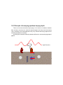
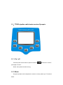
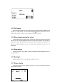
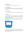
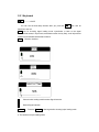
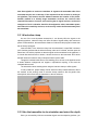
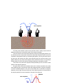
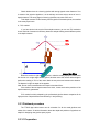
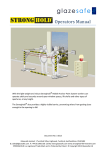
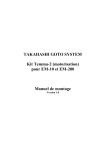
TT 2000 Pipeline & Cable Locator
User Manual
1.1 TT2000 Pipeline & Cable Locator
The TT2000 Pipeline & Cable Locator consists of a Transmitter and a Receiver, used
in the underground utilities route locating, the depth measuring and long distance tracing.
We adopted multicoil electromagnetism technology on TT2000 Pipeline & Cable Locator,
enhanced the pipeline localization to decide the depth precision and the goal pipeline
recognition capability, also could accurately carry on tracing and the localization in the
pipeline crowded complex region to the goal pipeline. Thus TT2000 Pipeline & Cable
Locator is widely used in the telecommunication, electric, tap water, natural gas, physical
prospecting, town planning and so on..
The TT2000 Pipeline & Cable Locator has many optional accessories, thus increased
their use, and expanded their application scope.
Before use TT2000 Pipeline & Cable Locator, please read this handbook carefully.
1.2 Security
The safety comes first, don’t neglect the security problem, and use TT2000 Pipeline &
Cable Locator certainly to have to follow the strict standard.
When uses some special methods, for example sends the transmitter signal directly
in the charged electric cable or poke probe in the pipeline with high pressure, only
personnel who have certain qualifications can do.
The Pipeline & Cable Locator is usually used on the transportation busy road, so
when using it, please be careful all the time and don’t forget Safety Comes First.
Attention: The transmitter has high output pressure (may reach 500V), do not touch
the wire which was stimulated!
1.3 Attentions
1.3.1 Depth survey
When active signal is existed on the simple pipeline ,only then Pinpoint has the
significance in the depth survey, requests not to be able to have the obvious signal on the
neighbor pipelines, the goal pipeline must be straight, moreover in 10 meters does not
have the T shape branch (Three Contacts). In addition, if the transmitter uses the
Induction mode, then when leaves the transmitter in the 20 meters to use the depth survey,
it is unable to obtain the exact result.
1.3.2 Cleanness maintenance
If needs to remove the silt or dirt on the pipeline & cable locator, please use the sponge
and tepid water, also may use the weak basicity soap to remove the stubborn dirt. Don’t
use any solvent to clean.
The TT2000 Pipeline & Cable Locator has certain rainproof function, but strictly
prohibits immerging it in the water, does not guarantee the waterproof and leak-proof
quality.
Do not deposit the instrument in the moist place, especially the place with caustic
gas.
1.3.3 Cell
When the power source is insufficient, charge cells or corresponding dry battery in
time, to guarantee the enough electric power. Do pay attention to the polarity of the cell.
The transmitter uses 10 1.2V 4.5AH Ni-Nh chargeable cell or 10 No.2 alkalescency
batteries, and the receiver uses 10 1.2V Ni-NH cell 1.5 AH Ni-Nh chargeable cell or 10
No.2 alkalescency batteries,. You cannot charge over 8 hours.
1.4 Services
Company to be equipped with the service center in SHANGHAI, it can provide
prompt and high quality service for the customer. When the instrument cannot work
normally, make sure it is the problem of instrument itself first, then please promptly contact
with the service center, and provides the instrument model, the serial number as well as
the detailed accurate breakdown description. The engineer in the service center can
provide some instructions and analyze the preliminary reason for the customer. If the
question still could not be solved, please deliver the instrument to the service center to do
repair.
2.1 Main functions:
1. Detect the underground cable and pipeline route
2. Measure the underground cable and pipeline depth
3. Determine the underground cable and pipeline insulation degree
4. Determine the route and depth of the cable and pipeline without touching the
transmission signal
2.2 Main characteristics
A. Use the newest integrated circuit and signal processing technology to achieve
outstanding test performance
B. The survey signal transmission includes:
1. Direct Inject method: In has Injected the spot on the pipeline to survey the route and
the burying depth, this method measuring accuracy is high, ant jamming ability.
2. Induction coupling method: In the railroad, the coal gas, the physical prospecting, the
line cable and so on does not have pours into the spot on the pipeline to survey the
route and the burying depth.
3.Inductive clamp method: As one of the important accessories, inductive clamp is used
for inflicting the transmitter signals directly onto the objective pipelines.
C. Different localization pattern for user to choose:
70% depth test method , Double loops direct reading method
D. Survey direct detection function
E. Receive survey conditio n automatically control function
F. The user may choose the dry cell or and the rechargeable cell according to the need
G. The signal 10 tiles high efficiency output, guaranteeing the farther probing range and
the detection depth
H. The automatic detection demonstrated the cell voltage
I. Owes the accumulated unsent telegrams police and automatically power off
J. With Inductive clamp and headphone can recognize many same direction pipelines.
2.3 Technical specifications
2.3.1 Technical specification
Technical specification of Transmitter:
Signal frequency:
a. Inject method
480Hz, 7.7KHz, and 31 KHz and CD mode
b. Induct mode
31 KHz
c. Inductive clamp method
31 KHz
Output Pressure
0-400VP-P automatic/manual adjust due to the insulated instance
Output wave shape
sine wave
Power source
12VDC 4.5AH in the Ni-MH cell
Peak output power
10W
Technical specification of Receiver:
Power loss
<1W
Power source
12VDC 1.5AH in the Ni-MH cell or 10 alkalescency batteries
Biggest test burying depth
4.5 meters (normal instance)
≤ 0.05h±5cm (“h” is pipeline depth)
The test burying depth error
≤ 5cm (normal condition)
The test route error
≤25MΩ
The test insulated error
Test the route and the efficient depth with Inject method
≥5Km (normal instance)
Test the route and the efficient depth with Induct method
≥3Km (normal instance)
Note: The objective pipeline has no insulated failure or other interruption in the
above-mentioned range in the normal instances.
2.3.2 Environmental request
-20 ℃ ~
Operating temperature
+
5
Storage temperature
Relative humidity
Atmospheric pressure
Environment noise
0
℃
-40 ℃ ~ +70℃
10%~90%
86~106KPa
≤60dB
2.3.3 Physical property
Name
Weight (Kg)
External Dimensions (mm)
Transmitter
3
348×236×180
Receiver
2.5
645×262×130
Entire machine (gross weight)
13.3
790×415×260
3.1 Transmitter’s principle of work
The transmitter is controlled by the miniature processor chip with large screen LCD in
English, choose function in the menu, when being used, examine the loading state and
the condition of the cell, if the pipeline has the high residual voltage, then cut off the
connection with the pipeline and alarm.
3.2 Receiver’s principle of work
The receiver is controlled by the miniature processor chip with large screen LCD in
English, and it can examine cell status when boot-strap.
3.2.1 Search route
When alternating current through a straight line conductor, it has a coaxial alternating
current magnetic field around this conductor, puts a loop in this magnetic field, it will Induct
the same frequency alternating current in the loop, the Induction tension size is decided
by the position of this loop in magnetic field, when magnetic line direction is parallel to the
loop, the loop Inducts the voltage horizontal ponderance is biggest, like the chart 3.3 left
shows; When the loop is vertical to the magnetic line direction, the Induction voltage
horizontal ponderance is smallest, like the chart 3.3 right shows. From this can judge the
route of a cable.
3.2.2 Principle of surveying pipelines burying depth
There are two same horizontal loops laying in the receiver, the distance between
them is known, sees chart 3.4, obtain the signal strength of the loop over the surveying
route, according to the electromagnetic theory, may calculate the burying depth size of
unknown goal pipeline conversely.
According to the Induction electricity faradism difference to calculate burying depth of
pipeline.
1.2m
Signal Intension
d
4.1 Test
Every TT2000 has to be tested before leaving factory with eligible certificate. 4.2
When using the cell must have sufficient electricity, concrete operation methods as below:
4.2.1 Turns on the instrument to let the cell discharge until the cell symbolize on the menu
into "X", at this moment the terminal voltage of cell is 11V.Attention: don’t let the cell
discharge excessively.
4.2.2 Meets the alternating current, at this moment the indicating lamp is not bright, then
meet the cell, at this moment the green light is bright.
4.2.3 Insert the BNC of the charger into the BNC connector jack, the red light shines.
When charging is over, the red light is bright.
4.2.4 Controls total duration of charging in 5 ~ 6 hours.
4.2.5 When charging, don’t have to separate the alternating current or to insert and pull
out the plug, otherwise must repeat 4.2.1 ~ 4.2.4 processes.
Before use the TT2000 Pipeline & Cable Locator, please read this handbook.
The pipeline& cable locators’ encasement listing:
A Transmitter
One
B Receiver
One
C Take-along bag
One
D User manual
One
E Transmitter charger
One
F Receiver charger
One
G Earthing stick
One
H Output line
One
I Inductive clamp
One
J Headphone
One
5.1、TT2000 pipeline cable locator receiver Synopsis
5.1.1. On / off
Press the power source button to open the receiver,
controls the on and off,
press again to close it.
Notice: don’t press the button too long.
5.1.2. Mode
Key-press operate mode is adopted; the receiver is mainly made up of 7 functional
button.
------------to control on and off
Mode-----------for choosing signal loading mode: Inject/Induct/headphone
↑ --------------- In measuring, plus manual acting to increase.
↓ ------------- --In measuring, plus manual acting to decrease.
Route------------choose peak value/valley value( orientation) to measure, it is tolerated as
automatically
optimize
accommodate
estate,
automatically
plus
accommodation is 1-99, press ↑,↓to enter manual acting accommodation
estate.
Depth--------------to measure the depth of the pipeline.
Light-----------tone up the LCD’s well-regarded tune, press backlight button to tune on/off
5.1.3 Cell status
Show cell states continually, receiver uses picture to show pressure, altogether there
are files, you must recharge it in time when it appears , when it is lower than 10V, the
LCD will give an alarm, and will automatically tune off after 3 seconds.
5.1.4 Route (peak value/valley value)
In Inject/Induct mode to press route to choose plane antenna for peak value response,
and you can also choose uprightness antenna for valley value response. The precision of
peak value is much higher than that of valley value, therefore, peak value response must
be used in ordinary orientation, you can use valley value response to check it, or to do
quick track.
5.1.5 Plus control
Indicating currently signal’s blow up value by amplifier plus percentage to show it on
the top left corner.
5.1.6 Backlight
Press this button to tune on the light, press again to tune off.
5.1.7 Figure display
It shows the response of the signal of the receiver, it can also provide the information
send by other functions.
A
99□
Route
注注注入
2456
45﹪
99:Signal relatively plus value, 1-99, on manual acting, press ↑ -or ↓to amend this value.
A: automatically route measure , press↑ or ↓to enter manual acting to adjust the
measure , M route: currently is measuring,press depth to do depth measure.
: Peak value mode,the value is biggest right over the road. Press route-to enter valley
value measure in route measuring,the symbol change into
:Valley value mode,the value is smallest right over the road, meanwhile it can
do route orientation,
、
means the route is at the left or right side of the measurer.
: Headphone method: the headphone will get the strongest response intensity on
the objective pipeline which has already been inflicted the transmitter signal.
Inject:the current mode is Inject,press mode-to enter Induct, show Induct
: it is the signal’s stick picture,the thicker, the stronger;the shorter, the smaller,
the length is in accordant with the relatively percentage.
2456: Shows the intensity of the route signal.
45%: Use percentage to show the signal.
5.1.8 Depth
Press depth to measure the depth of the objective pipelines, and it shows the test
result by centimeter, place the receiver right over the pipeline and make the surface in
right-angle with the ground, adjust the delicacy to make the reading in the range, press
depth to see the depth and press route to retune to the working mode.
If there is a strong radiate field, maybe there’s a radio station nearby, the measure
method at this time is make the antenna’s underside 5 centimeters’ higher than the ground,
and reduce 5 centimeters from the result, that is just the pipeline depth.
5.1.9 LCD
LCD shows output signal、mode and all kinds of functions.
5.1.10 Keyboard
Control the keyboard to choose operating mode and kinds of functions.
5.1.11 Cell sources
Unscrew the fastening screws of the top of the cell top to open the cell storehouse,
there are 1 cell box contains 10 cells, when it is short of electricity, please recharge it or to
change all the cells.
5.1.12 Accessories
Charger、take-along bag、earthing line、user manual、Inductive clamp and headphone.
5.1.13 Receiver
Inner are the receiver antennas, choose the peak value mode, the machine surface is
in a right angle with the ground, the antenna will give peak value response. Choose valley
value response, whatever the orientation of the machine surface; it can give valley value
response to the objective pipelines.
5.2 TT2000 Pipeline & Cable Locator Transmitter’s Synopsis
Panel interface
The transmitter adopts high capability MPU to control ,easy and convenient to
operate with English menu. It has the function of memorizing the output signal intensity, in
Inject mode you can do real time measure to check the output electric. Press button
requiring 8s backlight to save energy.
5.2.1 Keyboard
------------- On/Off
You can see the boot-strap interface after you press the
and it will do
detection to the cell.
Mode use for choosing signal loading mode: Inject/Induct or back to the signal
accommodate estate; in Inject mode, transmitter test the circuitry firstly, to do left pressure
measure and insulated characteristic measure.
Mode
Diversion interface
↑
Choose Induct loading mode/Increase Signal Intension
↓
Reduce Signal Intension
Transmit
Press the Transmit to load signal after choosing Inject loading mode.
a. The interface at Inject loading mode
b. The interface at Induct loading mode
c. The interface at Inductive clamp loading mode
5. 2.2 LCD
LCD shows output signal、mode and kinds of functions.
5.2.3 Cell
The transmitter can give cell status directions on the LCD, if the cell power is low, the
cell sign will flash and output break off signal before turning off, the transmitter can be
filled with 10 alkalescency cells/rechargeable cells.
5.2.4 Connect cables
Crewel cables with line nip can directly connect the transmitter signals with the
objective pipelines, the red nip link to the pipeline and the black one link to the ground.
5.2.5 Earthing stick
To earthing and to provide signal loop.
5.2.6 Inductive Clamp
It is a good method to recognize many same direction pipelines, especially the lines
in the pipes. You can directly nip the objective lines to load signal.
5.3 Detect methods
The TT2000 Pipeline & Cable Locator uses the power supply to track and orient the
transmitter signals.
5.3.1 Surveys Methods
The transmitter sends the special signals to the pipelines by direct Inject or Induct
coupling, and then do orientation and track.
5.3.1.1 Inflict transmitter signals
The operator must choose the technique to inflict best transmitter signal and the least
coupling domino effect. Guaranteeing send enough track signals, use lowest signal to
save cell power and reduce coupling effect.
Two ways of inflict transmitter signals in common use: direct connection and Induct
divisor.
Whatever way to choose, you must assure that the objective pipelines can distribute
a certain distant signal electric current loop, or the locator cannot detect the objective
pipelines.
The transmitter can contact the capacitance. Earth the pipelines if it is necessary.
Enter into the signal output estate automatically if there’s no remain pressure on the
pipelines, if there’s high pressure, you will hear an alarm, meanwhile the measure will not
continue, please measure again after finding out the causes.
Note: If the pipelines’ which under the transmit point insulated block value is small
(less than 1kΩ, or the measurement is 0Ω) or it is near the cable tie-in box, then the
signal may leak or cannot bring Induct current. So you can properly move the
transmitter to get the strongest Induct coupling signal.
5.3.1.2 Direct connect method
Direct connect method is fit for tracking the cables、water pipes and gas pipes
distribute systems.
Link the connect cables to the transmitter output jack, one (red) line to the objective
pipelines, eliminating the rust if it is necessary to guarantee good electric contact. Another
(black) line link to the grounding point, it may be several meters distant from the objective
pipelines, and had better be in a right angle with the possible route of the objective
pipelines.
The transmitter LCD may show the value of the output electricity.
If the output electricity is too small, you must check the grounding situation of transmitter
and the objective pipelines change the grounding position or water the dry sand if it is
necessary.
5.3.1.3 Induct method
In the transmitter, there’s a transmit loop, you can directly Induct the signals onto the
pipelines under the transmitter, for the deeper objective pipelines, the efficiency is low, this
method is usually used at the place where the depth is less than 2 meters.
What should be attention is the signal can not only Induct the objective pipelines, and
also do to close-by pipelines. Don’t use Induct method to inflict the signal to the
well-insulated pipelines, unless the two ends of the pipelines can effectively ground.
Turn on the transmitter power supply, place the transmitter right over the pipelines,
and make the transmitter in a line with the pipelines. And you can locate the pipeline at
least 30 meters away from the transmitter.
Note: The transmitter will send radiation signal to the air and pipelines. So at a
distance of the shooting near the local workstation machines, there might be some
problems, in order to determine the receivers are positioning themselves rather
than direct pipeline to receive a transmitter air signal to the transmitter side of the
movement may be one or two-step, if the response from the receiver is moving to
see pipelines, said receiver and the distance between the location of fire planes.
Another method is to directly target transmitter receivers, the receivers then
respond if the same or increase, said receiving the air signal receivers, such as the
emergence of such a situation should be investigated to reduce transmitter power,
and reduce the sensitivity receivers, receivers may need to be 50 meters away from
the transmitter.
5.3.1.4 Inductive clamp
As one of the most important accessories, it can directly inflict the signal to the
objective pipelines. Inductive clamp can inflict all kinds of signals safely with continuous
power. Please attention; the transmission distance of Inductive clamp signal is nearer than
that of directly link signal.
Insert the BNC of the Inductive clamp into the transmitter’s output BNC connector
jack. Hitch the pipelines with the Inductive clamp, make sure it’s closed, and then open the
transmitter, link well the pipelines so that the signal can be transmitted to the pipelines. It
is normal that there’s buzzer or shake, it doesn’t do harm to the instrument. Don’t touch
the BNC when the Inductive clamp clamps the electric power cable.
Though the insulated cable has no real earthing point, as lone as the pipeline buried
a certain distance underground can support a capacitance coupling, it can track the
insulated cable as well.
The transmitter cannot earthing when using the Inductive clamp to inflict signals.
In many instances, people always choose Inductive clamp method instead of direct
link method, as the working mode of inductive clamp method is like the pipeline has
already been slice off and link the transmitter to the two incisions.
5.3.2 Use the transmitter to do orientation and orient the depth
Since you successfully inflict the transmitter signal onto the objective pipelines, you
can track and do orientation to the pipelines with the receiver. The position and the depth
are the most important information of underground pipelines.
5.3.2.1 Use the transmitter to do orientation for the objective
pipelines
Transmitter boot-strap interface
TT2000 provides three detect modes: peak value and valley value and headphone.
a. Peak Value Method:
Peak levels in response to two days of receiving a target pipelines signal strength
level, the antenna and top receiver antenna signal intensity for the poor response. Peak
model is the top receivers in the target pipelines will be the largest (peak) response.
Airframe associate transmitters receivers will face, made at the walk along the curve
around, adjust sensitivity to the scale readings remain within. When peak response, local
stop moving back and forth on both sides of the pipelines receiver to identify peak
response. Then receiver local moves in the direction of maximum pause. Raising receiver
lightly back and forth movement of the peak to determine the precise location of pipelines
position in the target for the markings.
The precision and the ability to avoid disturbing of peak value method is much higher
than the valley value method, it must be used in all kinds of works. The response when
receiver is right over the objective pipelines is zero (valley value).
A
zero response
b. Valley Value Method:
The valley value method is quick but the precision is bad, it mainly uses to track the
pipelines and check the correctness of peak value method orientation.
Tune the receiver to the peak value response to speed up tracking the pipelines; you
can hold the receiver at any trend, because the valley value response doesn’t rest on the
orientation of the pipelines. When you walk along the pipeline, you may move the receiver
left and right, and observe the valley value response right over and two sides of the
pipeline. When you use valley value response mode, and as the receiver is in a right angle
with the cables, the LCD may show the left/right arrowhead to the pipeline position.
Tune back to the peak value response mode periodically so as to check the exact
position of the objective pipelines.
Use peak value mode to do orientation and mark it. And then tune back to the valley
value response mode, note down the valley value response position, if they are accordant,
it can be considered pinpoint. If they are not accordant, then it should be not pinpoint.
Attention, the two signs are at the same side of the objective pipeline, the fact position of
the objective pipelines is near the position of the peak value response.
A
zero response
B
Pipeline
c. Headphone method:
It has a good effect to pipelines general cannot be recognized such as many parallel
pipelines, aerial cable.
The headphone will get the biggest response intensity on the objective pipelines
which have been inflicted transmitter signal.
When the direction of the arrowhead of headphone is parallel to the pipeline direction,
the signal is the biggest. The other way round the signal is the smallest.
5.3. 2.2 Depth measure
As long as inflicting the transmitter signal onto the pipelines, you can do depth
measure to objective pipelines. Pay attention to the proceedings hereinafter in operating:
1. Do depth measure in the middle part of the pipeline, the depth of detecting must be
within the depth-detect extension. It’s the sticking point for big-diameter pipelines.
2. Don’t do depth measure at the pipeline crook or nearby the T shape branch pipe, you
can get best precision measure 10 meters depart from the pipeline.
3. The depth measure is unfaithful when there’s intensive interfere or the transmitter
signal has already been coupling on the close-by pipelines.
4. Avoiding inflict signals using Induct divisor in depth measure, if you have no alternative,
the transmitter must leave 30meters away from the depth measure point.
5. If the transmitter signal is transmit to the near-by pipelines, you should inflict the signals
onto the objective pipelines by both sides connect method.
6. Two measure ways: speediness measure and precision measure, press “depth” two
times to enter precision measure. Direct reading divisor is in common use.
7. When detecting depth, the signal value should be over 3000, and the value fluctuate is
small.
a、Direct reading method
It can do depth measure of 4.5 meters. It’s simple and convenient, the precision
measure is high when there’s no interfere. But it has the shortcoming of a sort of
anti-jamming ability.
1.2m
Signal Intension
d
First, use the transmitter to do orientation for the response of the objective pipeline
peak value and peak valley. If the two positions are differ, it shows that the interfere exits,
you may try again by inflicting transmitter signals to eliminate the needless signals, and do
depth measure at the place where the response of two signals are accordant.
Place the receiver right over the pipeline and the machine’s surface must be in a right
angle with the pipelines and the ground, adjusting the sensitivity to make sure that the
number is within the measure range. Press “depth” to show the depth, press again to
return to the former mode.
If it turns out a strong radiate place, then there may be a radio station, meanwhile,
you may measure the depth by making the antenna 5cm higher than the ground, detract
5cm from the depth shown to know the pipeline’s depth.
If you doubt about the result, you may check again by making the receiver 0.5m
higher than the ground, if the result raise 0.5m, it proves the former result right.
The depth measure precision can reach 5% if the situation is proper. But, the
operator is impossible to know whether the situation is proper or not. So, we must adopt
some techniques as follows to check some key reading.
Is the pipeline route straight? At least it must be straight in 5 meters at the both sides
of the measure point. Is the signal stabilizing in 10 meters? If it is stabilizing, you may do
depth measure at the former measure point.
Check whether there is a close-by pipeline with strong signals at the distance of 3 or
4 meters to the objective pipelines. It is the ordinary and most serious cause of error in
depth measure. The strong signal of close-by pipelines may cause 50% error.
To do depth measure a little far away from the pipeline orientation points, the smallest
is the most pinpoint one.
b、70% method
If you have doubt in the result of direct depth measure, you can use 70% method to
check. this kind of measure is efficiency because it adopts reading several different points
to do depth measure.
When the receiver is right over the pipeline, make the reading a proper number while
the receiver is in a right angle with the ground, and then move the receiver left and right to
decline the reading to 70% of the value. Mark the two points and measure the distance.
The distance is right the depth of the pipeline.
Note: Do not use this method when the depth is less than 20cm.
If the results of the two-depth measure are close, it tunes out that the precision of the
depth measure is guaranteed.
70% method is widely adopted by the professional pipeline detect companies for its
high precision of depth measure and efficiency in anti-jamming.
5.3.3 Fieldwork procedure
The TT2000 pipe cable locator can do orientation for all the metal pipelines and
cables of the extent. So all the information about the depth and positions of pipelines are
helpful for designing new pipeline pave project.
5.3.3.1 Preparation
Work over the locale before operating the pipe&cable locator. The well cover, street
lights and all the signs refer to cable and pipes are considerable.
Make sure the extent, including the edge belt of it.
5.3.3.2 Gridding search
Park the transmitter on each point of the extent in reasonable alternation, do gridding
research, in order to detect the ignored pipelines which detected by no-power research
and other pipelines.
5.3.3.3 Track, orientation and depth measure
Inflicting the transmitter signals to the pipelines and the cables, this can be linked. For
example: the container, the valve, the streetlights and so on, track the part out of the
extend and mark it.
For the pipelines need to be identified, you can track them till the well cover,
streetlight and so on, and then you can inflict the transmitter signals, back to the extent.
Do orientation and depth measure to all the key points and characteristic points of
each pipelines of the area, mark them and note the relevant pipeline information and
detect results. And then coordinate the data to do the pipeline-distributing map.
6.1 T shape pipeline detection
As long as you had made tracks for the pipeline and marked, you can track again
along the pipeline with the receiver, but this time you may track one-step distant from one
side of the pipeline, which has already been tracked, and make the receiver run parallel
with the pipeline. The locator cannot detect the signal send by the main pipeline (or the
signal is little), but the response to the branch pipeline is in evidence.
The most reliable method for locating the pipeline is to inflict the transmitter signal to
the end part of the branch pipeline. The signal streams from the branch pipeline to the
main pipeline, and then streams between both sides of the main pipeline’s double
directions. The airframe surface is in a right angle with the main pipeline, you can track the
signal along the main pipeline, the receiver will response to it as zero values (valley top)
right over the tie-in of the T shape branch pipeline. The reverse position of the valley is the
nicety place of the T shape branch pipeline’s tie-in.
6.2 Parallel pipelines detection
In pipeline detection, the parallel pipelines is the sort of universal instance, in the area
where the pipelines are dense, the receiver may always receive the interfere signal from
the close-by pipelines, it may brings us the difficulty in recognizing and tracking the
objective pipelines, and effecting the precision of orientation and depth-fix. Therefore we
must adopt some methods to the best of our abilities to minish the influence of the
close-by parallel pipelines’ coupling signal.
First, we’d better not use the Induct method in the area where the pipelines are dense,
but to use the coupling ability of direct-join method to inflict transmitter signal. In such
instance, we’d better use peak value response mode orientation, measuring the depth by
70% method, so as to reduce the windage.
In commonly instances, the response of the receiver to the objective pipeline should
be bigger than it to the close-by pipeline; we can recognize and track the objective
pipeline by the response of the receiver. But if the close-by pipeline is nearer to the ground
surface, the receiver’s response to the close-by pipelines will surpass it to the objective
pipelines. We cannot recognize and track the objective pipeline only by the receiver’s
response, so we must use direct-join method.
6.3 Ordinary instances in detection
6.3.1 Track the cables from tie-in or connection box
Before inflicting transmitter signal, it is necessary to take the common tie-in apart, in
order to track the objective pipeline. If you want to track all cables start from the
connection box, you may operate the transmitter at the Induct mode, put the transmitter by
one side of the connection box in line with the cables tracked.
6.3.2 Long-distance cable track
In order to transmit the transmitter signal long enough distance, it is necessary to
take the earth connection of the cable off. When the tie-in or connection be earthed
because of the safety or the prevent thunder protection, electric emerge (avoid
overloading) discharge ware is used to replace the earthing of the tie-in or connection so
as to protect the cables, making the uninterrupted orientation possible.
6.3.3 Tie-in pinnacle pulse
Most cable tie-in or connection may produce a pinnacle pulse at the response to the
receiver, working experience and the realization of local situations are helpful for the
operator to distinguish whether the pinnacle pulse figures that there’s a connection box.
6.3.4 Metal protective fence
The cables usually burying under the ground of the outside of the metal protect fence
of the highroad, the signal will coupling to the stretch metal protective fence. It is difficult to
track for the metal protective fence is near from the transmitter under layer antenna.
Taking up the receiver and hold the under layer antenna parallel with the metal protective
fence, overcoming this difficulty is easy.
6.3.6 Street lighting cables
The transmitter signal is always connected to the metal pillar. If it is cement lamp
standard—unless the lighting cables can be grounded via connecting to the examine and
repair shelf, or you need to connect the transmitter signal with the lighting cables’ metal
shield. Knowing the relevant position and depth of the lighting cables (along with the other
street establishment of the same lighting system) is quite helpful for tracking lighting
cables, one connect point may inflict signals to the cables of a large piece of area.
It is viable to inflict signals to other electric power cables by using lamp standard, but
the signal may be very little, for it maybe had transmitted for a long distance before it
returned to the transformer substation, and it must stream again from the system. Here we
can adjust the transmitter to high output power mode and tune up the output power. This
method is viable for the cables which are not convenient or difficult to inflict signals to
locate.
As for the cables taking part from the wooden telegraph pole, cement telegraph pole
or the lighting pillar, you can operate the transmitter at the Induct mode, and put it
alongside the pillar, which is in a right angle with the ground to inflict signals.
6.3.7 Track metal gas pipe
Generate pipeline orientation and track technique can be used to detect the
steeliness gas pipe.
Some gas pipes have insulative tie-in, to offer the inner house an effective earth loop.
Locating the gas pipe under or roadside of the highroad, you can use single end
connect method to connect the transmitter to the valve, and connect the earthing cables to
the valve box’s metal shelf, guaranteeing to nip the line nip well, can offer well electric
connection. You may brush and scrape the oil paint or the rust before connecting if it is
necessary.
Sometimes one section of the pipeline may has some insulated tie-in, you should
inflict the transmitter signal to the far-forth end of every insulated tie-in, and the higher
signal frequency should be adopted. There maybe the tie-in can hardly let the signal go
through in some other iron pipes, you may track the iron pipes in Induct way, and move
the transmitter to the position last detect the signal.
Brand together the techniques as above; you can track the iron pipelines triumphantly
commonly.
If all the tie-in of the metal pipelines are insulative, you cannot locate it by generate
method, one way is to use extend-in method to locate the pipeline tie-in, that is extend the
transmitter’s forepart into the pipeline, in order to locate the pipeline tie-in, and then make
the transmitter perpendicular to the pipeline, searching apex and valley response at every
tie-in to nicety locate to the pipe.
7.1 Check-up
Both the transmitter and receiver have rechargeable batteries inside; you must
recharge it before using.
Note: There are two chargers—one for the transmitter, one for the receiver, the
charging methods are due to the charger instruction.
7.2 Elimination For common malfunction
Examine and Repair for the malfunction
Num.
1
malfunction
No display with “du du” noise.
possibility
solution
low cell
To measure the
pressure of the charger
receptacle with
multimeter (prevents
short circuit) , if it is
lower than 10.5V,it must
be recharged.
2
The display is not clear when
opening or during the operating
process, the light is not enough
or it does not work.
3
The value shown is on the low
side when testing the route.
low cell
As above.
the signal is too feeble
Press ▲
the signal isn’t loaded.
Check the transmitter
output line.
错误!未找到引用源。 The
4
5
Operating with Induct method,
transmitter isn’t placed over
can measure the signal distance
The transmitter should
the pipeline.
from the transmitter within 50
be placed over the
meters, cannot measure the 错误!未找到引用源。 The
pipeline.
signal outta 50 meters.
transmitter isn’t placed
parallel to the pipeline.
The receiver cannot receive
The transmit intensity isn’t
signal when using immit method.
adjusted well.
To adjust to the proper
transmit intensity.
6
As above.
The signal output pin doesn’t
stick in well.
Stick the pin well in.
7
When using Induct method or
immit method, can hardly
receive signal.
When signal outputting,
when it displays or, you
must get it recharged.
Use it after it has been
fully recharged.
7.3 Maintain service
All products and the accessories of our company had been well tested when
designing, producing and before leaving factory, guaranteeing the trustiness of the
performance and the choiceness of the quality. If you have any problem in operating,
please first consult this user manual. If you need more consultation, please contact the
after service department.
7.4 After service promises.
Our products carry out maintaining for life, outer the maintaining period, you only
have to pay for the cost charge.
We respond to the clients’ advices and ideas to the
product quality in 24 hour.