1
MON °
DEL
917.258863
OWNER'SMANUAL
Assembly
Operation
®Customer Responsibilities
®Service and Adjustments
- Repair Parts
For answers to your questions
about this product, Call:
1-800-659-5917
Sears Craftsman Help Line
5 am - 5 pro,Mon- Sat
CAUTION:
Read and follow
all safety rules and instructions
before operating
this equipment.
SAFETY
RULES
Practices for Ride-On
Safe Operation
Mowers
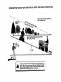
IMPORTANT: THIS CUTTING MACHINE IS CAPABLE OF AMPUTATING HANDS AND FEET AND THROWING OBJECTS
FAILURE TO OBSERVE THE FOLLOWING SAFETY INSTRUCTIONS
COULD RESULT IN SERIOUS INJURY OR DEATH°
I.
•
o
•
•
•
•
•
•
•
•
•
•
•
•
•
II.
Ul. CHILDREN
GENERAL OPERATION
Read, understand, and follow all instructionsin the m_nual
and on the machine before starting..
Only a11owresponsible adults, who are familiar with the
instructions, to operate the machine+
Clear the area of objects such as rocks, toys, wire, etc._,
which could be picked up and thrown by the blade.
Besure the area isclear ofother people beforemowing+ Stop
machine if anyone enters the area.
Never carry passengers°
Do not mow in reverse unless absolutely necessary_+Always
look down and behind before and while backing+
Be aware of the mower discharge direction and do not point
it at anyone. Do not operate the mower without either the
entire grass catcher or the guard in place+
Slow down before turn+ng+
Never leave a running machine unattended Always turn off
blades, set parking brake, stop engine, and remove keys
before dismounting
Turn off blades when not mowing
Stop engine before removing grass catcher or unclogging
chute
Mow only in daylight or good artificial light+
Do not operate the machine while under the influence of
alcohol or drugs
Watch for traffic when operating near or crossing roadways.
Use extra care when loading or unloading the machine into
a traitor or truck+
Tragic accidents can occur if the operator is not alert to the
presence of children.
Children are often attracted to the
machine and the mowing activity+ Never assume that
children will remain where you last saw them.
•
Keep children outof the mowing area and under the watchful
care of another responsible adult
•
Be alert and turn machine off if children enter the area
•
Before and when backing, look behind and down for small
children.
°
Never carry children, They may fall off and be seriousIy
injured or interfere with safe machine operation+
•
Never allow children to operate the machine°
•
Use extra care when approaching btind comers, shrubs,
trees, or+other objects that may obscure vision.
IV.
•
•
•
SLOPE OPERATION
•
Slopes are a major factor related to loss-of-control
and
tipover accidents, which can result in severe injury ordeath+
All slopes require extra caution, tf you cannot back up the
slope or if you feel uneasy on it, do not mow it
•
°
DO:
•
Mow up and down slopes, not across+
•
Remove obstacles such as rocks, tree limbs, etc
•
Watch for holes, ruts, or bumps
Uneven terrain could
overtum the machine. Tall grass can hide obstacles°
•
Use slow speed. Choose a low gear so that youwill not have
to stop or shift while on the slope
•
Follow the manufacturer's recommendations for wheel
weights or counterweights to improve stability.
•
Use extra care with grass catchers or other attachments
These can change the stability of the machine°
•
Keep all movement on the slopes slow and gradual Do not
make sudden changes in speed or direction.
•
Avoid starting or stopping on a slope. If tires lose traction,
disengage the blades and proceed slowlystraight down the
slope
•
•
•
•
SERVICE
Use extracare tnhandllnggasoline and other fuels. Theyare
flammable and vapors are explosive+
Use only an approved container.
Never remove gas cap or add fuel with the engine
running. Allow engine to cool before refueling Do not
smoke.
Never refuel the machine indoors°
Never store the machine or fuel container inside where
there is an open flame, such as a water heater.
Never run a machine inside a closed area.
Keep nuts and bolts, especially blade attachment bolts,tight
and keep equipment in good condition.
Never tamper with safety devices. Check their proper
operation regularly+
Keep machine free of grass, leaves, or other debds build+up.
Clean oil or fuel spillage° Allow machine to cool before
storing.
Stop and inspect the equipment if you strike an objecL
Repair, if necessary, before restarting
Never make adjustments or repairs with the engine running+
Grass catchercomponents are subject to wear, damage, and
deterioration, which could expose moving parts or allow
objects to be thrown. Frequently check components and
replace with manufacturer's recommended parts, when necessary.
Mower blades are sharp and can cut. Wrap the blade(s) or
wear gloves, and use extra caution when servicing them,
Check brake operation frequently. Adjust and service as
required°
LOOk for this Symbol
to point out im-
CAUTIONtt!
BECOMEALERTIH
YOUR
portant safety'
precautions.
It means
SAFETY IS INVOLVED.
DO NOT:
•
Do not turn on slopes unless necessary, and then, turn slowly
and gradually downhill, if possible.
•
Do not mow near drop oils, ditches, or embankments The
mower could suddenly turn over if a wheel is over the edge
of a cliff or ditch, or if an edge caves in+
o
Do not mow on wet grass Reduced traction could cause
sliding.
•
Do not try to stabilize the machine by putting your foot on the
ground
•
Do not use grass catcher on steep slopes.
CAUT'O":
Always--disconnect
spark plug
spark plug in order to prevent accidental
wire and placewire where itcannot contact
starting when setting up, transporting,
adjusting or making repairs.
•_lb
VVARNING
........
................
&_
........
The engine exhaust from this product contains chemicals known to the State of California to cause cancer, birth defects, or other
reproductive harm.
2
............
i
lU ....
........
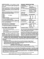
PRODUCT SPECIFICATIONS
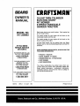
CONGRATULATIONS
on your purchase of a Sears
Tractor.. It has been designed, engineered and manufactured to give you the best possible dependability and
performance.
Should you experience any problem you cannot easily
remedy, please contact your nearest Sears Authorized
Service CentedDepartment.
We have competent welltrained technicians and the proper tools to service or repair
this tractor.
"MODEL
NUMBER
917_258863
SERIAL
NUMBER
DATEOFPURCHASE
THE MODEL AND SERIAL NUMBERS WILL BE FOUND
ON A PLATE UNDER THE SEAT.
YOU SHOULD RECORD BOTH SERIAL NUMBER AND
DATE OF"PURCHASE AND KEEP IN A SAFE PLACE
FOR FUTURE REFERENCE.
AGREEMENT
A Sears Maintenance Agreement is available on this product,. Contact your nearest Sears store for details.
CUSTOMER
RESPONSIBILITIES
=
Read and observe the safety rules_
•
Follow a regular schedule in maintaining, caring for and
using your tractor°
Follow the instructions under "Customer Responsibilities" and "Storage" sections of this owner's manual.
-
................
: .........
LIMITED
GASOLINE CAPACITY
AND TYPE:
3°5GALLONS
UNLEADED REGULAR
OIL CAPACITY:
Wl FILTER: 442PINTS
W/O FILTER: 3.7 PINTS
SPARK PLUG:
(GAP: °030")
CHAMPION RC12YC
VALVE CLEARANCE:
NOT ADJUSTABLE
GROUND SPEED (MPH):
Forward
1st
2nd
3rd
Reverse
TRANSAXLEOIL
CAPACITYAND TYPE:
4 QUARTS
SAE 30 API-SF/SG/SH
TiRE PRESSURE:
FRONT: 14 PS1
REAR: t0 PS1
CHARGINGSYSTEM;
i5 AMPS @3600 RPM
BATTERY:
AMP/HR:
35
MIN. CCA:
280
CASE SIZE: U1R
BLADE BOLTTORQUE:
27-35 FT_LBS.
LO
0.7
1,.4
243
0°9
HI
1.7
3.3
5.4
2ol
with a spark arrester meeting applicable local or state laws
(if any). if a spark arrester is used, itshould be maintained
in effective working order by the operator.
In the state of California the above is required by law
(Section 4442 of the California Public Resources Code)°
Other states may have similar laws. Federal laws apply on
federal lands. A spark arrester for the muffler is available
through your nearest Sears Authorized Service Center/
Department (See REPAIR PARTS section of this manuat)_
WARNING:
This tractor is equipped with an internal
combustion engine and should not be used on or near any
unimproved forest-covered, brush-covered or grass-covered land unless the engine's exhaust system is equipped
i,lll
18.5
OILTYPE (API-SF/SG/SH): SAE 10W30 (above 32°F)
SAE 5W_30(below 32°F)
Please read and retain this manual. The instructions will
enable you to assemble and maintain your tractor properly_
Always observe the "SAFETY RULES".
MAINTENANCE
HORSEPOWER:
Ill
TWO YEAR WARRANTY
ON CRAFTSMAN
RIDING
EQUIPMENT
For two (2) years from the date of purchase,if this CraftsmanRiding Equipment is maintained,lubricated and tunedup according
tothe instructions
in the owner'smanual,Searswillrepairor replace, free of charge,any partsfound to be defectivein material or
workmanship.
ThisWarrantydoes not cover:.
= Expendableitemswhichbecomewornduringnormaluse,suchas blades,spark plugs,air cleaners,belts,etco
•
Tire replacementor repair causedby puncturesfrom outsideobjects,such as nails,thorns,stumps,or glass.
°
Repairs necessary because of operatorabuse, negligence,improperstorageor accidentor thefailure tomaintainthe
equipmentaccording tothe instructions
containedin the owner'smanual°
= Ridingequipmentusedfor commercialor rentalpurposes°
LIMITED
90 DAY WARRANTY
ON BATTERY
For ninety (90) days from date of purchase, if any battery included with this riding equipment proves defective In matedal or
workmanship and our testing determinesthe battery wtl!not hold a charge, Searswillreplacethe battery at nocharge_
IN-HOME WARRANTY SERVICE ON YOUR CRAFTSMAN RIDING EQUIPMENT IS AVAILABLE AT NO-CHARGE FOR 30
DAYS FROM THE DATE OF PURCHASE° PLEASE CONTACT YOUR NEAREST SERVICE CENTER_ AFTER 30 DAYS FROM
THE DATE OF PURCHASE, WARRANTY SERVICE IS AVAILABLE BY TAKING YOUR CRAFTSMAN RIDING EQUIPMENT TC
YOUR NEAREST SEARS SERVICE CENTER. (IN-HOME WARRANTY SERVICE WILL STILL BE AVAILABLE AFTER 30 DAYS
FROM THE DATE OF PURCHASE BUT A STANDARD TRIP CHARGE WILL APPLY°) THIS WARRANTY APPLIES ONLY
WHILE THIS PRODUCT lS IN THE UNITED STATES°
This Warranty gives you specific legal rights, and you may also have other rights which may vary from state to state.
SEARS, ROEBUCK AND CO., D/817 WA, HOFFMAN ESTATES, IL 60179
3
INDEX
E
A
Accessories ................................................5
Adjustments:
Brake ................................................ 22
Carburetor .........................................27
Clutch Pulley .......................................
22
Gauge Wheels ....................................
14
Mower
Front-To-Back ............................21
Side-To-Side ............................ 20
Throttle Control Cable ................... 26
Air Filter, Engine ......................................19
Air' Screen, Engine ...................................19
Assembly ..............................................7-10
Electdcak
Interlocks and Relays .....................25
Schematic ...........................................
31
Wiring Diagram ............................. 32
Engine:
Air Filter ................................................
19
Air Screen ............................................
19
Cooling Fins ...............................................
18
Oil Change ............................................
18
Oil Level ..................................................
t8
Oil Type .............................................
14,18
Preparation .......................................15
Repair Parts ...............................50-57
Starting ....................................................
15
Storage ..............................................
28
B
Battery:
Charging .............................................8
Cleaning ............................................18
Starting with Weak Battery .......... 24
Storage ........................................... 28
Terminals ......................................... 18
Belt:
Motion Drive
Removal/Replacement .............23
Mower Ddve
Removal/Replacement ........... 21
Mower Blade Drive
Removal!Replacement ............ 22
Blade:
Sharpening .......................................17
Replacement ................................... 17
Brake Adjustment .....................................22
C
Carburetor Adjustment ..............................
27
Clutch Pulley .............................................
22
Controls, Tractor ................................... 12
Customer Responsibilities ............. 16-19
Engine:
Air Filter,.........................................19
Air Screen ....................................19
Cooling Fins ...................................
18
Engine Oil ............................. !4,18
Fuel Filter .................................. 19
Spark Plug(s) .................................
19
Tractor:.
Battery ............................................18
Blade .............................................17
Lubrication Chart .........................16
Maintenance Schedule ............ t6
Tire Care ............................ 8,17,24
Transaxle .....................................17
Cutting Height, Mower .......................... 13
Storage ................................................
28
Operation ........................................... 11-15
Operating Mower ................................. 14
Options:
Accessories ..........................................
5
Spark Arrester ............................. 3,40
P
Parking Brake .......................................
12-13
Parts Bag ......................................................
6
Parts, Replacement/Repair ...............32-47
Product Specifications
3
.................................
R
Repair Parts .........................................
32-47
F
S
Filter:
Safety Rules ..................................................
2
Air Filter....................................................
19
Fuel ...........................................................
19
Seat ............................................................. 8
Oil ..........................................................
19
Service and Adjustments .................20-27
Fuel:
Carburetor ........................................ 27
Storage .................................................
28
Clutch Pulley ................................ 22
Type ..........................................................
14
Fuse ..................................................25
Fuse ..................................................................
25
Hood RemovaVlnstaHat[on ............ 25
Motion Drive Belt
Removal/Replacement ............ 23
H
Mower Drive Belt
Headlights .....................................................
25
Removal/Replacement ........... 21
Hood RemovaVInstallatlon .......................
25
Mower Blade Drive Belt
Removal/Replacement ............ 22
Mower Adjustment
L
Front-to-Back ..............................21
Leveling Mower Deck .............................20
Side-to-Side .................................20
Lubrication:
Mower Removal/Installation ......... 20
Chart ....................................................
16
Tire Care ..................................8,17,24
Engine .....................................................
18
Slope Guide Sheet ..................................59
Spark Plug(s) ........................................ 19
M
Specifications
Maintenance Schedule ...........................16
Starting the Engine ............................. 15
Mower:
Steering Wheel ................................... 7,23
Adjustment, Front-to-Back .............21
Stopping the Tractor .............................. 15
Adjustment, Side-to-Side .................
20
Blade Replacement ........................17
Storage ........................................................
28
Blade Sharpening ............................17
Cutting Height ..................................13
T
Installation ....................................... 20
Throttle
Control
Cable
Adjustment ........26
Operation ........................................ 14
Removal ...........................................20
Tires
Mowing Tips .......................................... 15
Troubleshooting Chart ................... 29-30
Muffler ...................................................... 19
Transaxle .................................... 17,48-49
Spark Arrester ............................. 3,40
...........................................
3
...............................................
8,17,24
W
0
Warranty
Wiring Diagram ..................................... 32
Wiring Schematic ....................................31
....................................................
Oit:
Cold Weather Conditions ......... 14,18
Engine ................................................I8
4
3
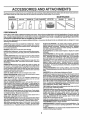
ACCESSORIES AND ATTACH
i
i Hi,ll=ll, ii ii
=,,H,i=,=,L,,
These accessories and attachments were available throughmost Sears retail outletsandservice centers when the tractorwas purchased_
Most Sears stores can order these items for you when you provide the model number of your tractor.,
ENGINE
SPARK PLUG
MAINTENANCE
GAS CAN
ENGINE OIL
FUELSTABILIZER
AIR FILTER
BLADES
BELTS
PERFORMANCE
Sears offers a wide variety of attachments that fit your tractor..Many of these are listed below with brief explanations of how they can help
you, This list was current at the time of publication;however, it may change in future years - more attachments may be added, changes
may be made in these attachments, or some may no longer be available or tit your model,. Contact your nearest Sears store for the
accessories and attachments that are available for your tractor.
Most of these attachments do not require additional hitches or conversion kits (those that do are indicated) and are designed for easy
attaching and detaching.
SLEEVE CULTIVATOR is 43 inches wide, Prepares ground for
seeding,helpsweed control.Steel frame holds5 adjustablesweeps.
Adjustsverttcaly, horizontaHyo(Requires sleeve hitch,) Optional
accessory: steel furrow opener for wider openings for potatoes,
corn, and other deep-seeded crops_
SLEEVE HITCH for use with master lift system,, Single pln couples/
uncouples,
SNOWTHROWER has 42-inch swath° Drum-type auger handles
powdery andwet/heavysnow_ Mounts easily with slmple pin arrangement. Discharge chute adjusts from tractor seat° 6-tnch diameter
spout discharges snow 10 to 50 feet. Lift controlled at tractor seat°
(Use with chains and wheel weightsand/or rear drawbar weighL)
SPRAYERS use 12-volt DC electric motor that connectsto the tractor
battery or other 12-volt source, Includes booms for automatic
spraying and hand held wand for spot spraying. Wand has adjustable
spray pattem_ For applying herbicides, insecticides, fungicides and
liquid fertiitzerso
SPREADER/SEEDERS make seeding,fertilizing, and weed killing
easy. Broadcastspreadersare also usefulfor granular de-icers and
sand.
SWEEPERS let you collect grass clippings and leaves.
TILLER has 8 hp engineto prepare seed beds, cultivate, andcompost
garden residue, Chain-drivetransmlssion_Six 1l-inch diameterone
piece heat-treated steel tines. -riits 30-inch path. (Requires sleeve
hitch°) Or use 5 hp tow-behind TILLER with 36-inch swath to prepare
seed beds, cultivate and compostgarden residue. Tiller has its own
built-in lift and depth control system and does NOT require a sleeve
hitch. Fits any lawn, yard or garden tractor, Simply hook up to the
tractor drawbar and gol Optional accessories for 5 hp tiller convert
unit for dethatching, aerating, hilling,oowithout tools.
TIRE CHAINS are heavy duly; closely spacedextra-largecrosslinks
give smoothride, outstandingtraction,
TRACTOR CAB has heavy dulyvinylfabric over tubular steel frame,
ABS plastictop; clear plasticwindshieldoifers 360 degree visibility.
Hinged metal doors with catch, Keeps operator warm and dry.
Remove vinyl sides and windshields for use as sun protector in
summer. Optional accessories Include: tinted/tempered solid
safety glass windshield with hand operated wiper;, 12-volt amber
cautionlightfor mounting on cab top.
VACS for powerfulcollectionof heavy grass clippings and leaves.
Optional wand attachment to pickupdebrisin hard-to-reach places.
VACICHIPPER includesa chipper-shredder_
WEIGHT BRACKET for drawbar for snowremovalapplications. Can
be mountedon front of tractorfor plowingapplications, Uses (1) 55
IboweighL
WHEEL WEIGHTS for rear wheels provideneeded tractionfor snow
removal or dozing heavy materials,
AERATOR promotesdeep rootgrowth for a healthy lawn,.Tapered
2o5-inchsteel spikes mounted on 10-inch diameter discs puncture
holesin soilat closeintervalstoretmoisture soakin. Steelweighttray
for increasedpenetration.
BUMPER protectsfront end of tractorfrom damage.
CARTS make haulingeasy. Varietyof sizes available, plusaccessories such as sidepanel kits,toolcaddy,cartcover,protectivematand
dolly_
CORING AERATOR lakes small plugs out of soil to allow moisture
and nuldents to reach grass roots, 30-inch swath, 24 hardened steel
codng tips, 150 Ib, capacity weighttray,
DISC HARROW has 2 gangs of 4 steel blades that angle from 10 to
20 degrees, 40 incheswide° Can hook 2 unitsin tandem, (Requires
sleeve hitch°)
DOZER BLADE removes snow; grades dirt, sand and gravel 48
incheswide, 17 incheshigh, clears 44*inch path when angled. Master
lift control lever for operator ease, Spring trip for snow removal on
uneven pavement; built-in float for blade to fotlow ground contour,
Reversible, replaceable scraper bar. (Use withtire chains and wheel
weights and/or rear drawbar weighL)
EASY OIL DRAIN VALVE makes oil changes easier, faster,,
FRONT NOSE ROLLER canters in front of mower deck to reduce
chances of"scalping" on uneven terrain
GANG HITCH lets you tow 2 or 3 pull-behind attachments at
once, such as sweepers, dethatchers, aerators (not lot use with
rollers, carts or other heavy attachments).
MULCH RAKE/DETHATCHER loosens soil and flips thatch and
matted leaves to lawn surfacefor easy pickup_Twenty springtine
teeth. Usefulto preparebare areasfor seeding. Availablefor front or
rear mounting. HIGH PERFORMANCE REEL-ACTION SPRING
TINE DETHATCHER covers36*inchwidepathand tossesthatch into
large hopper, Mounts behind tractor.
PLOW turns soil 6 inches deep, cuts 10-inch furrow_ Crank adjustment controlsdepth, 3-position yoke sets width. Heavy steel landsfde
for straight furrowing, (Requires sleeve hitch,)
RAMP TOPS AND FEET let you load and unload tractor from a
pickup truck. Use with 2 x 8 or 2 x t0 lumber,,
REARGRADER BLADE ts42incheswide andoperated frbm ddvefs
seat° Reversible steel blade can be angled at 30 degrees for grading.
Reverses for pushing snow backwards. (Requires sleeve hitch.)
ROLLER for smootherlawn surface. 36-Inch wide, 18-inch diameter
water-tight drum holds up to 390 lbso of weight, Rounded edges
prevent harm to turf° Adjustable scraper automatically cleans drum,,
5
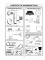
CONTENTS
OF HAR
PACK
i
ijl
, iiiiiilllJl
i
i iilllll]ll
i iiiiii
link
J/
_uIII
ii
Parts Bag contents shown full size
Parts packed separately
in carton
(1) Shoulder Bolt 5/16-18
Seat
Steering
Wheel
Mufcher
Plate
O
Video
Cassette
(1) Knob
(1) Washer 17/32 x 1_3/16 x 12 Gauge
(2) Screws #10 x5/8
(2) Lock Washers #10
Manual
'
Parts Bag
i,ijl,llJlllll
illlllll
Parts bag contents
(2) Weld Nuts #10
................................
not shown full size
Wheels
(2) Shoulder
Bolts
_(2)
(2) Washers 3/16 x 3/4 x 16 Gauge
Gaug_
(2) Washers 3/8
x 7/8 x 14 Gauge
Wheel
teering
Insert
O
(2)lock
CenterNuts
_"'(2)
:...............................
(2) Hex Bolts
1/4.20 x 3/4
/,._--_.
(2) Washers__
9/32 x 5/8 x 16 Gauge
:.
Front Link Assembfies
ii
_
(2) Hex
(2) Keys
(2)Lock
_
_...
_Hook
Assemblies
Slope Sheet
Washers 1/4
i i iiii
6
I
iii
Steering
Sleeve
II
iiii
LY
Your new tractor has been assembled at the factory with exception of those parts left unassemb_ed for shipping purposes.
To ensure safe and proper operation of your tractor all parts and hardware you assemble must be tightened securely. Use
the correct tools as necessary to insure proper tightness°
TOOLS
REQUIRED
FOR ASSEMBLY
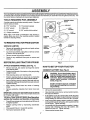
STEERING WHEEL
INSERT
A socket wrench set will make assembly easier, Standard
wrench sizes are listed.
(2) 7/16" wrenches
(1) Tire pressure gauge
(1) 9/16" wrench
(1) Utility knife
(1) 112"wrench
(1) 3/4" socket w!drive ratchet
(t)
HEX BOLT
_,_
Phillips screwdriver
When right or left hand is mentioned in this manual, it
means when you are in the operating position (seated
behind the steering wheel).
STEERING
UNPACK
CARTON
o
Remove all accessible loose parts and parts cartons
from carton (See page 6).
°
Cut, from top to bottom, along lines on all four corners
of carton, and lay panels flaL
Remove mower and packing materials.
°
_WASHER
WHEEL
TO REMOVE TRACTOR FROM CARTON
•
STEERING
STEERING
WHEEL
ADAPTER
STEERING
SLEEVE
I/
Check for any additional loose parts or cartons and
remove.
I
I
ATTACH
•
STEERING
WHEEL (See Fig. 1)
Slide steering sleeve over steering shafL
Position steering wheel so cross bars are horizontal
(left to right) and slide onto steering wheel adapter.
°
Secure steering wheel to steering shaft with hex bolt,
lock washer and large flat washer previouslyremoved.
Tighten securely.
,
CONNECT
L tl
•
°
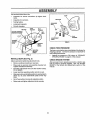
BATTERY (See Fig. 2)
....it
,,
Llll
i
,,,,
o
Lift hood to raised position,
°
Open terminal access doors, remove terminal protective caps and discard_
•
If this battery is put into service after month and year
indicated on label (label located between terminals)
charge battery for minimum of one hour at 6-10 ampso
First connect RED battery cable to positive (+) battery
terminal with hex bolt, flat washer, lock washer and hex
nut as shown. Tighten securely.
Connect BLACKgroundingcable to negative (-) battery
terminal with remaining hex bolt, flat washer, lock
washer and hex nut° Tighten securely.
Close terminal access doors.
TO ROLLTRACTOR OFFSKID (See Operation
section for location and function of controls)
Release parking brake by depressing clutch!brake
pedal.
Place gearshift lever in neutral (N) position.
Roll tractor backwards off skid.
I
Positive terminal must be connected
first to prevent sparking from accidental grounding.
Remove protective materials from tractor hood and
gdllo
IMPORTANT: CHECK FOR AND REMOVE ANY STAPLES
IN SKID THAT MAY PUNCTURE TIRES WHERE TRACTOR
IS TO ROLL OFF SKID.
°
i//
CAUTION: Do not short battery terminals by allowing a wrench or any other
object to contact both terminals at the
same time. Before connecting battery,
remove metal bracelets, wristwatch
bands, rings, etc.
•
Press liftlever plunger and raise attachment lift lever to
its highest position.
/
HOW TO SET UP YOUR TRACTOR
Snap steering wheel insert into center of steering
wheel.
o
/
FIG. 1
Remove hex bolt, lock washer and large flat washer
from steering shall
Positionfront wheels of the tractorso they are pointing
straight forward°
°
,
_ _t"
/
BEFORE ROLLING TRACTOR OFF SKID
=
LOCK
•
°
-
7
ASSEMBLY
: ...::
i
,i,,,,,:,, :....
Use terminal access doors for:
•
°
Inspection for secure connections (to tighten hardware).
Inspection for' corrosion°
o
Testing battery.
•
°
Jumping (if required).
Periodic charging°
HF..XNUT'
SEAT
SEAT PAN
\
SHOULDER
BOLT
LOCK
WASHER
FLAT
DISCARD TERMINAL
PROTECTIVE CAPS
HEX
BOLT
FLAT
WASHER
ADJUSTMENT
KNOB
TERMINAL
ACCESS
DOOR
....
FIG. 3
',
POSITIVE
(RED)
CABLE
CHECK TIRE PRESSURE
NEGATIVE
The tires on yourtractor'were overinflated at the factory for
shipping purposes. Correct tire pressure is important for
best cutting performance°
(BLACK)
CABLE
FIG. 2
°
INSTALL SEAT (See Fig. 3)
CHECK BRAKE SYSTEM
Adjust seat before tightening adjustment knob°
•
Remove cardboard packing on seat pan.
•
Place seat on seat pan and assemble shoulder boil
Tighten shoulder bolt securely.
°
°
=
Assemble adjustment knob and fiat washer loosely.
Do not tighten_
Lower seat into operating position and sit on seal
Slide seat until a comfortable position is reached which
allows you to press clutch/brake pedal all the way
down,
•
Get off seat without moving its adjusted position.
•
Raise seat and tighten adjustment knob securely.
Reduce tire pressure to PSI shown in "PRODUCT
SPECIFICATIONS" on page 3 of this manual,
After you learn how to operate your tractor, check to see
that the brake is properly adjusted. See 'q'O ADJUST
BRAKE" in the Service and Adjustments section of this
manual.
8
ASSEMBLY
i
,i,,ii,,,,ii,,i,l,_UU_ll,,ll,,
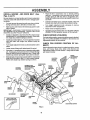
INSTALL MOWER
Figs. 4 and 7)
....
AND DRIVE BELT
(See
Be sure tractor is on level surface and mower suspension
arms are raised with attachment lift control° Engage parking brake,
•
Cut and remove ties securing anti-sway bar and belts,
Swing anti-sway bar to left side of mower deck,.
° Slide mowerundertractorwith discharge guardto right
side of tractor.
IMPORTANT: CHECK BELT FOR PROPER ROUTING IN
ALL MOWER PULLEY GROOVES. INSTALL BELT INTO
ELECTRIC CLUTCH PULLEY GROOVE,
•
Install second front linkin L,,H.front suspension bracket
only and retain with single loop retainer spring as
shown.
.
Turn height adjustment knob counterclockwise until it
stops.
Lower mower linkage with attachment lift control°
Place the LHo suspension arm on inward pointing deck
dPin,if necessary, rock and raise front of mower to align
eck pin with the hole in suspension arm. Retain with
double loop retainer spring with loopsdown as shown.
Slide left side of mower back and install the unattached
front link in top hole of the L.Ho front mower bracket.
Retain with single loop retainer spring as shown.
o
.
°
CHASSIS
BRACKET
DOUBLE LOOP
RETAINER SPRING
(Inward pointing
deck pins)
Piace the Roll,, suspension arm on inward pointing
deck pin° If necessary, rock and raise front of mower
to align deck pin with the hole in suspension arm_
Retainwith double loop retainer spring with loops down
as shown°
°
Connect anti-sway bar to chassis bracket under left
footrest and retain with double loop retainer spring.
°
Turn height adjustment knob clockwise to remove
slack from mower suspension,
°
°
Raise mower to highest position.
AssembIe gauge wheels (See "TO ADJUST GAUGE
WHEELS" in the Operation section of this manual)°
CHECK MOWER LEVELNESS
Install one front link in top hole of the R,H. front mower
bracket and R.Hofront suspension bracket. Retain with
two single loop retainer springs as shown.,
=
°
For best cuttingresults, mower should be properly leveled.
See '3"0 LEVEL MOWER HOUSING" in the Service and
Adjustments section of this manual.
CHECK
BELTS
FOR PROPER
POSITION
OF ALL
See the figures that are shown for replacing motion, mower
drive, and mower blade drive belts in the Service and
Adjustments section of this manual Verify that the belts
are routed correctly°
FRONT
SUSPENSION
BRACKETS
ELECTRIC
CLUTCH
PULLEY'
SUSPENSION
ARMS
FRONT
MOWER
BRACKET
FRONT
, LINK
SHOULDER
BOLT
SINGLE
LOOP
RETAINER
SPRINGS
GAUGE
WHEEL
/
3/8 WASHER
3/846
CENTER
LOCKNUT
DOUBLE LOOP
RETAINER
SPRING
ANTI-SWAY
BAR
USE PLIERS FOR
RETAINER SPRINGS
IDLER /
PULLEY
DISCHARGE
FIG, 4
9
GUARD
......
x
ii
, i,ii,i
IHIIll
:
................................................................
I Illlll
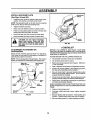
INSTALL MULCHER PLATE
(See Figs. 5A and 5B)
•
DEFLECTOR
SHIELD
Install two fatch hooks to mulcher plate using screw,
washer', lock washer, and weld nut as shown.
NOTE: Pre-assemble weld nut to tatch hook by inserting
weld nut from the top with hook pointingdown_
•
Tighten hardware securely.
-
Raise and hold deflector shield in uprightposition.
•
Place front of mulcher plate over front of mower deck
opening and slide into place, as shown°
Hook front latch into hole on front of mower deck.
Hook rear latch into hole on back of mower deck.
°
HOOKS
guard from mower. Raise and hold
CAUTION:
not remove
discharge
guard whenDoattaching
mutcher
plate
and allow it to rest on plate while In
operation.
ill
ii
FIG. 5B
...............
TO CONVERT TO BAGGING
DISCHARGING
,/"CHECKLIST
OR
BEFORE YOU OPERATE AND ENJOY YOUR NEW
TRACTOR, WE WISH TO ASSURE THAT YOU RECEIVE
THE BESTPERFORMANCE AND SATISFACTION FROM
THIS QUALITY PRODUCT.
Simply remove mulcher plate and store in a safe place.
Your' mower is now ready for' discharging or installation of
optional grass catcher accessory.
PLEASE REVIEW THE FOLLOWING CHECKLIST:
NOTE; it is not necessary to change blades. The mulcher
blades are designed for discharging and bagging also.
WELD NUT
FROM THE "fOP
HOOKPOINTS
DOWN
,/
/
All assembly instructions have been completed.
No remaining loose parts in carton.
v"
Battery is properly prepared and charged,
1 hour at 6 amps)o
#'
Seat is adjusted comfortably and tightened securely.
(Minimum
#" All tires are properly inflated. (For shipping purposes,
the tires were overinflated at the factory).
LOCK
WASHER
LATCH
HOOK
SCREW
/
Be sure mower'deck is properly leveled side-to-side/
front-to-rear for best cutting results. (Tires must be
properly inflated for leveling).
#" Check mower and drive belts. Be sure tt_eyare routed
propertyaround pulleys and inside att bett keepers.
/
Check wiring. See that all connections are stillsecure
and wires are properly clamped.
WHILE LEARNING HOW TO USE YOUR TRACTOR, PAY
EXTRA ATTENTION TO THE FOLLOWING IMPORTANT
ITEMS:
WELD
NUT
LATCH
HOOK
LOCK
WASHER
v" Engine oil is at proper level.
,/" Fuel tank is filled with fresh, clean, regular unleaded
gasoline.
4" Become familiar with all controls - their location and
function. Operate them before you start the engine.
MULCHER
PLATE
FIG. 5A
,/
10
Be sure brake system is in safe operating condition.
i
...........
i
,rv...............
_.........
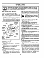
OPERATHON
These symbols may appear on your tractor or in literature supplied with the product.
Learn and understand
FAST
SLOW
CLUTCH
LIGHTS ON
OVER TEMP
LIGHT
DIFFERENTIAL
LOCK
PARKING BRAKE
LOCKED
UNLOCKED
FORWARD
BATTERY
CAUTION OR
WARNING
REVERSE
ENGINE ON
ENGINE OFF
OIL PRESSURE
FUEL
CHOKE
MOWER HEIGHT
their meaning.,
L
REVERSE
MOWER LIFT
NEUTRAL
ATTACHMENT
CLUTCH ENGAGED
HIGH
LOW
ATTACHMENT
CLUTCH DISENGAGED
PARKING BRAKE
IGNITION
HYDROSTATIC FREEWHEEL
(Hyd_ Modelsonly)
DANGER, KEEP HANDS AND FEETAWAY
'11
KNOW YOUR TRACTOR
READ
THIS
OWNER'S
MANUAL
AND SAFETY
RULES
BEFORE
OPERATING
YOUR
TRACTOR
Compare the illustrations with yourtractortofamiliarize yourself withthe locationsof various controlsand adjustments, Save
this manual for future reference,
ATTACHMENT CLUTCH swrI'CH
_,%\
LIGHT SWITCH
LIFT
LEVER
PLUNGER
_
CHOKE CONTROL
LIFT LEVER
CLUTCH/BRAKE
PEDAL
PARKING BRAKE
LEVER
THROTTLE
CONTROl,,
RANGE SHIFT
LEVER
HEIGHT
ADJUSTMENT
KNOB
GEARSHIFT LEVER
FIG. 6
Our tractors conform to the safety standards of the American National Standards institute,
ATTACHMENT CLUTCH SWITCH- Used toengage mower
blades or other attachments mounted to your tractor,
LIFT LEVER- Used to raise and lower mower deck or other
attachments mounted to your tractor.
LIFT LEVER PLUNGER- Used to release attachement lift
lever when changing its position°
RANGE SHIFT LEVER - Allows high (H) or low (L) speed
for' all forward and reverse gears,
CLUTCH/BRAKE PEDAL - Used for deciutching and
braking the tractor and starting the engine.
PARKING BRAKE LEVER- Locks clutch/brake pedat into
the broke position,
GEARSHIFT LEVER - Selects the speed and direction of
tractor°
CHOKE CONTROL- Used when starting a cold engine.
IGNITION SWITCH - Used to start and stop the engine,
AMMETER - Indicates battery charging (+) or discharging
LIGHT SWITCH - Turns the headlights on and off,
HEIGHT ADJUSTMENT KNOB- Used to adjust the mower
height,,
THROTTLE CONTROL-, Used to control engine speed°
12
OPEBATRON
i1,111,11[_1,11 _
,i,,i,1,,,,,,i,, i,i
.... 1,1,,11,1
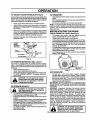
The operation of any tractor can result in foreign objects thrown into the eyes, which can
result in severe eye damage. Always wear safety glasses or eye shields while operating
your tractor or performing any adjustments or repairs. We recommend a wide vision safety
mask over the spectacles or standard safety glasses.
NOTE: Under certain conditions when tractor is standing
idle with the engine running, hot engine exhaust gases may
cause "browning" of grass. To eliminate this possibility,
always stop engine when stopping tractor on grass areas.
HOW TO USE YOUR TRACTOR
TO SET PARKING
BRAKE (See Fig, 7)
Your tractoris equipped with an operator presence sensing
switch. When engine is running, any attempt by the
operator to leave the seat without first setting the parking
brake will shut off the engine,
•
Depress clutch/brake pedal into full "BRAKE" position
and holdo
,
Place parking brake lever in "ENGAGED" position and
release pressure from clutch/brake pedal Pedal should
remain in "BRAKE" position. Make sure parking brake
will hold tractor secure°
IGNITION
KEY
PUSH IN TO
CAUTION: Always stop tractor completely, as described above, before leaving the operator's position; to empty
grass catcher, etc.
TO USE THROTTLE
ATTACHMENT
CLUTCH SWITCH
PULL OUT TO
"ENGAGE"
TO USE CHOKE CONTROL
THROTTLE
CONTROL
LEVER
TO MOVE FORWARD
(See Fig, 7)
RANGE
LEVER
"DISENGAGED"
POSITION
HEIGHT
ADJUSTMENT
KNOB
GEARSHIFT
LEVER
TO ADJUST MOWER
(See Fig. 7)
•
Move throttle control to slow position.
NOTE: Failure to move throttle control to stow position and
allowing engine to idle before stopping may cause engine
to "backfire".
°
CUTTING HEIGHT
(See
The cutting heightis controlledby turning the height adjustment knob in desired direction°
•
Turn knob clockwise ((-_) to raise cutting height.
Turn knob counterclockwise (P_)to
lower cutting
height.
The cutting height range is approximately 1-1/2" to 4-1/2'L
The heights are measured from the ground to the blade tip
with the engine not running. These heights are approximate and may vary depending upon solt conditions, height
of grass and types of grass being mowed,
° The average lawn shouldbe cut toapproximately 2-1/2
inches during the cool season and to over 3 =nches
during hot months, For healthier and better looking
lawns, mow often and after moderate growth,
•
For best cutting performance, grass over 6 inches in
height should be mowed twice_ Make the first cut
relatively high; the second to desired height.
MOWER BLADES *
° Move attachment clutch switch to "DISENGAGED"
position.
GROUND DRIVE•
Depress clutch/brake pedal into full "BRAKE" position.
o Move gearshift lever to neutral (N) position.
ENGINE -
Turn ignition key to "OFF" position and remove key.
Always remove key when leaving tractor to prevent
unauthorized use,
Never use choke to stop engine,
AND BACKWARD
Fig. 7)
FIG. 7
°
(See Fig. 7)
The direction and speed of movement is controlled by the
gearshift lever,
° Start tractor with clutch/brake pedal depressed and
gearshift lever in neutral (N) position°
•
Move gearshift and range shift levers to desired positiono
° Slowly release clutch/brake pedal to start movement,
IMPORTANT: BRING TRACTOR TO A COMPLETE STOP
BEFORE SHIFTING OR CHANGING GEARS. FAILURE
TO DO SO WILL SHORTEN THE USEFUL LIFE OF YOUR
TRANSAXLE,
POSITION
STOPPING
(See Fig. 7)
Use choke controlwhenever you are starting a cold engine,
Do not use to start a warm engine,
° To engage choke control, pull knob out° Slowly push
knob in to disengage.
CHOKE
CONTI
CLUTCH/
BRAKE
PEDAL
"DRIVE"
POSITION
CONTROL
Always operate engine at full throttle.
= Operating engine at less than full throttle reduces the
battery charging rater
°
Full throttle offers the best mower performance.
13
OPERATION
TO ADJUST GAUGE WHEELS (See Fig. 8)
TO TRANSPORT
Gaugewheels arepropedyadjustedwhen theyareslightlyoffthe
ground when mower is at the desired cutting height in operating
position. Gauge wheels then keep the deck inproper position to
help prevent scalping in most terrain cond_ionSo
•
•
Adjust gauge wheelswith tractoron a flat level surface.
=
Adjust mower to desired cutting height (See 'q*OADJUST
MOWER CUTTING HEIGHT" in the OperaUonsection of
this manual)°
o
With mower in desired height of cut POSition,gauge wheels
should be assembled so they are slightly off the ground°
lns_l gauge wheel in appropriatehole with shoulder bolt, 3/
8 washer, and 3/8-16 Iocknutand tighten securely.
°
Raise attachment lift to highest position withattachment lift
control.
° When pushingor towing your tractor',be sure gearshiftlever
is in neutral (N) position.
°
Do not push or tow tractorat more than five (5) MPH.
NOTE: To protect hood from damage when transporting your'
tractor on atruckor a trailer, be sure hood is closed and secured
to tractor. Use an appropriate means of tying hood to tractor
(rope, cord, etcJ.
BEFORE STARTING THE ENGINE
CHECK ENGINE OIL LEVEL (See Fig. 9)
•
Repeat for opposite side installing gauge wheel in same
adjustment hole.
The engine in your tractor has been shipped, from the
factory, already filled with summer weightoil.
Check engine oit with tractor on level ground.
Unthread and remove oil fill cap/dipstick; wipe oil off. Reinsert the dips'_ckintothe tube and rest oil fill cap on the tube.
Do not thread the cap onto the _be. Remove and read oil
level. If necessary, add oil until FULL_ mark on dipstick is
reached. Do not overfill.
°
•
•
For cold weather operation you should change oil for easier
starting (See _31LVISCOSITY CHART" in the Customer
Responsibil_es section of this manual)°
To changeengine oil, see the Customer' Responsibilities
section in this manual.
•
FIG. 8
TO OPERATE MOWER (See Rgs. 6 and 7)
Your tractor is equipped with an operator presence sensing
switch. Any attempt by the operator to leavethe seat w_ththe
engine runningand the attachment clutch engaged will shut off
the engine.
•
Select desired height of cut.
•
Lower mower with attachment lift control.
•
Start mower blades by engaging attachment clutch controI.
•
TO STOP MOWER BLADES- disengage attachment
clutch control.
OIL FILL CAP/
.'K
FIG. 9
ADD GASOLINE
•
H
without either the entire grass catcher,
CAUTION:
operate or
thethe
mower
on mowers Do
so not
equipped,
discharge guard in place.
TO OPERATE ON HILLS
ii
oo°=0r,
•
•
•
°
•
•
•
J
with slopes greater than 15° and do not
drive across any slope.
Choose the slowest speed before starting up or down hills°
Avoid stopping orchangingspeed on hiHs_
If slowing isnecessary, move throttle control leverto slower
pos_ono
tfstoppingisabsolutely'necessary, pushclutch/brake
pedal
quickly to brake pos_on and engage partdngbrake_
Move gearshiftlever to 1stgearand rangeshiftlever to low
(L)position. Be sureyou haveallowedroomfortractortoroll
slightly as you restartmovement.
To restart movement,slowly release parkingbrake and
clutch/brakepedal.
Make all turnsslowly°
14
Fill fuel tank. Use fresh, clean, regular' unleaded
gasoline with a minimum of 87octane. (Use of leaded
gasoline will increase carbon and lead oxide deposits
and reduce valve life). Do not mix oil with gasoline.
Purchase fuel in quantities that can be used within 30
days to assure fuel freshness.
IMPORTANT" WHEN OPERATING IN TEMPERATURES
BELOW 32QF(0°C), USE FRESH, CLEAN WINTER GRADE
GASOLINE TO HELP INSURE GOOD COLD WEATHER
STARTING.
WARNING: Experience indicates that alcohol blended
fuels (called gasohol or using ethanol or methanol) can
attract moisture which leads to separation and formation of
acids during storage° Acidic gas can damage the fuel
system of an engine while in storage° To avoid engine
problems, the fuel system should be emptied before storage of 30 days or longer. Drain the gas tank, start the
engine and let it run until the fuel lines and carburetor are
empty. Use fresh fuel next season. See Storage instructions for additional information.
Never use engine or
carburetor cleaner products in the fuel tank or permanent
damage may occur.
filler neck. Do not overfill. Wipe off any
spilled
oil orFill
fuel.
not store,
spill
or
CAUTION:
to Do
bottom
of gas
tank
use gasoline near an open flame.
L
ILl
I
UIII
Jllll'llllllll
OPERATmON
,rlH"l"ln,,'lL _
•
TO START ENGINE (See Fig. 7)
When startingtheengine for thefirsttimeor iftheenginehasrun
outoffuel,itwilltakeextracrankingtimetomovefuelfromthetank
to theengine°
•
•
Siton seatinoperatingposition,depressclutch!brake
pedal
and set parkingbrake°
o
o
Placegear shift lever in neutral(N) position.
Move attachment clutchto"DISENGAGED" position.
o
•
Movethrottle controltofast position
o
°
PullchokecontroIout for a coldenginestart attempt. Fora
warm engine start attempt the chokecontrolmay not be
needed.
Note: Before starting, read the warm and cold starting procedures below.
•
=
Insert key into ignitionand turn key clockwise to "START"
positionand releasekeyassoon asenginestarts. Donotrun
starter continuously for more than fifteen seconds per
minute. If the engine does not start after several attempts,
push choke control in, wait a few minutes and try again. If
engine stilldoes notstart,pull the choke controlout and retry.
WARM WEATHER STARTING (50° F and above)
° When engine starts, slowIy push choke control in until the
engine begins to mn smoothly. If the engine starts to run
roughly, pullthe choke control out slightlyfor a few seconds
and then continue to push the control in slowly_
•
FIG. 10
MULCHING
The attachments and ground drivecan now be used. If the
enginedoes not accepttheload, restartthe engine and allow
itto warm up for one minute using the choke as described
above.
•
When engine starts, slowly push choke control in until the
engine begins to runsmoothly_Continue to push thechoke
control in small steps allowing the engine to accept small
changes in speed and load, untilthe choke control isfully in.
If the engine starts to run roughly, pull the choke control out
slightly for a few seconds and then continue to push the
controlinslowly.This mayrequire anenginewarrn-up period
from several secondsto severalminutes, depending on the
temperature.
o
The attachments can be used during the engine warm-up
period and may require the choke control be putled out
slightly°
o
NOTE: Ifat a high altitude (above3000 feet) or in cold temperatures (below 32 F) the carburetor fuel mixture may need to
beadjustedfor bestengine performanceoSee"TOADJUST
CARBURE-I'OR" inthe Service and Adjustments section of
this manual.
°
MOWING TIPS
o
•
o
°
MOWING TIPS
IMPORTANT;
FOR BEST PERFORMANCE,
KEEP
MOWER HOUSING FREE OF BUILT-UP GRASS AND
TRASH. CLEAN AFTER EACH USE.
o The special mulching blade will recut the grass clippings many times and reduce them in size so that as
they fall onto the lawn they will disperse into the grass
and not be noticed. Also, the mulched grass will
biodegrade quickly to provide nutrients for the lawn.
Always mulch with your highest engine (blade) speed
as this will provide the best recutting action of the
blades°
COLD WEATHER STARTING (50° F and below)
o
I 'J,l,II
When mowinglarge areas, start bytuming tothe rightso that
clippings will discharge away from shrubs, fences, driveways, etc. After one or two rounds, mow in the opposite
direction making lefthand turns untilfinished(See F3g.10)_
ifgrass isextremelytall, itshould be mowed twiceto reduce
load and possiblefire hazard from dried clippings. Make first
cut relatively high; the second to the desired height.
Do not mowgrasswhen itiswet. Wet grass wiIlplug mower
and leave undesirable clumps. Allow grass to dry before
movang.
Alwaysoperateengine atfullthrottlewhen mowingto assure
better mowing performance and proper discharge of mate_
daL Regulate ground speed by selectinga Iowenoughgear
to give the mower cutting performance as well as the quality
of cut desired.
When operatingattachments,select agroundspeedthatwill
suit the terrainand give best performance of the attachment
being used.
•
Tire chains cannot be used when the mower housing is
attached to tractor.
Mower should be properly leveled for best mowing performance. See "TO LEVEL MOWER HOUSING" in the
Service and Adjustments section of this manual.
The left hand side of mower shouldbe used for trimming.
Drive so thatclippings are discharged onto the area that has
been cut. Have the cut area tothe rightofthe machine. This
wilt result in a more even distribution of clippings and more
uniform cutting.
15
Avoid cutting your lawn when itis wet. Wet grass tends
to form clumps and interferes with the mulching action°
The best time to mow your lawn is the early afternoon.
At this time the grass has dried and the newly cut area
will not be exposed to the direct sun.
For best results, adjustthe rnowercutting height so that
the mower cuts off only the top one-third of the grass
blades (See Fig. 11). For extremely heavy mulching,
reduce yourwidth of cut on each pass and mow slowly.
Certain types of grass and grass conditlons may require that an area be mulched a second time to completely hide the clippings° When doing a second cut,
mow across or perpendicular to the first cut path.
Change your cutting pattern from weekto week. Mow
north to south one week then change to east to west the
next week. This will help prevent matting and graining
of the lawn.
FIG. 11
CUSTOMER
II
IIIIIII
II
I
LIIIIII
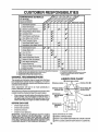
MAINTENANCE
AS YOU
IIIIIIIIII
I
lUlU
............
SCHEDULE
................................................
___
_._'__
COMPLETE
CheckBrakeOperation
V#
CheckTirePressure
iV _' If
V F
Check for Loose Fasteners
IV _
I _##7
R. Sha_e,_Rep_ace
MowerBia,_es
if
_,
c Lu, catiOncha. ...........€:
T
0
............
CheckBatteryLeve!/Recharge
CleanBatteryandTerminals
:
i .....
i€ :
....
L_
Ik
j
R
AdjustBlade Belt(s)Tension
.....
_5
AdjustMotion DriveBelt(s)Tension
V_e ,,., :'................ , ..........
Check Engine 0ii Level
ChanE"gioe
e O,
.........
.........
CleanAirFilter ...........
EN CleanAir Screen
G
|
............
1 234-
.
_nspect
iu.ier!SparkArresier
V'
.....1_2.................
V_2
....
_ ...........
ReplaceOil Filter(ff equipped)
V_t.2
Replace Air Fitter Paper Cartridge
_/2
ReplaceFuelFilter
,,,
, ,,,, ,, ,,,,,,,,,
if
,,, ,,,
Change more often when operating under a heavy load or In high ambient temperatures
Service more often when operating in dirty or dusty conditions.
if equipped with oil filter, change oil every 50 hours,
Replace blades more often when mowing In sandy soil,.
GENERAL
,
' '" ....
RECOMMENDATIONS
.
5 - if equipped with adjustable system,
6 - Not requited it equipped with maintenance-free battery,
7 - Tighten front axle pivot bolt to 35 fL.lbs, maximum,
Do not oved]gh_en
LU BRIOATION
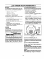
The warranty on this tractor does not cover items that have
been subjected to operator abuse or negligence. To receive
full value from the warranty, operator must maintain tractor as
instructed in this manual.
CHART
(_ TIE ROD BALL JOINTS
Some adjustments will need to be made periodically to
properly maintain your' tractor.
@ FRONT WHEEL _..:_-_-_.
-_1
_ FRONT WHEEL _)
All adjustments in the Service and Adjustmentssection of this
manual should be checked at least once each season.
Once a year you should replace the spark plug, clean or
replace air filter, and check blades and beltsfor wear. A
new spark plug and clean air filter' assure proper air-fuel
mixture and help your engine run better and last longer:
BEFORE EACH USE
•
Check engine oil level.
-
Check brake operation.
•
Check tire pressure.
Check for loose fasteners.
(bCHEC_'ADD'-._
( _',
IMPORTANT: DO NOT OIL OR GREASE THE PIVOT POINTS
WHICH HAVE SPECIAL NYLON BEARINGS.
VISCOUS
LUBRICANTS WILL ATTRACT DUST AND DIRT THAT WILL
SHORTEN THE LIFE OF THE SELF-LUBRICATING BEARINGS.
tFYOU FEEL THEY MUST BE LUBRICATED, USE ONLY A DRY,
POWDERED GRAPHITE TYPE LUBRICANT SPARINGLY.
5"1
(3:) SAE 30 MOTOR OIL API _ SF/SG
(_ GENERAL PURPOSE GREASE
REFER TO CUSTOMER RESPONSIBILITIES
"ENGINE" SECTION
(_) SPRAY SILICONE LUBRICANT (MOVE BOOTS TO LUBR|CATE)
16
CUSTOM
LITIES
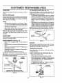
TO SHARPEN
BLADE (See Fig. 13)
Always observe safety rules when performing any maintenanceo
Care should be taken to keep the blade balanced.. An
unbalanced blade willcause excessive vibration and eventual damage to mower and engine,
BRAKE OPERATION
°
If tractor requires more than six (6) feet stopping distance
at high speed in highest gear, then brake mustbe adjusted.
(See "TO ADJUST BRAKE" in the Service and Adjustmerits section of this manual).
The blade can be sharpened with a file or on a grinding
wheel Do not attempt to sharpen while on the mower.
=
To check blade balance, you will need a 5/8" diameter
steel bolt, pin, or a cone balancer. (When using a cone
balancer, follow the instructions supplied with balancer),
•
Slide blade on to an unthreaded portion ofthe steel bolt
or pin and hold the bolt or pin parallel with the ground.
If blade is balanced, it should remain in a horizontal
position. If either end of the blade moves downward,
sharpen the heavy end until the blade is balanced°
TIRES
•
o
i
Maintain proper air pressure in all tires (See "PRODUCT SPECIFICATIONS" on page 3 of this manual).
Keep tires free of gasoline, oil, or insect control chemicals which can harm rubber.
NOTE: Do not use a nail for balancing blade. The lobes of
the center hole may appear to be centered, but are not°
Avoid stumps, stones, deep ruts, sharp objects and
other hazards that may cause tire damager
NOTE: To seal tire punctures and prevent fiat tires due to
slow leaks, tire sealant may be purchased from your local
parts dealer. Tire sealant also prevents tire dry rot and
corrosion°
.
CENTERHOLE
/
/
BLADE CARE
For best results mower blades must be kept sharp° Re_
place bent or damaged blades.
BLADE REMOVAL
(See Fig. 12)
FIG. 13
•
Raise mower to highest position to allow access to
blades°
V-BELTS
=
Remove hex bolt, Iockwasher and flat washer securing
blade_
°
Install new or resharpened blade with trailing edge up
towards deck as shown.
Check V-belts for deterioration and wear after 100 hours
and replace if necessary. The belts are not adjustable.
Replace belts if they begin to slip from wear,.
°
Reassemble hex bolt, lock washer and flat washer in
exact order as shown°
TRANSAXLE
Keep transaxle free from build-up of dirt and chaff which
can restrict cooling.
° Tighten bolt securely (30-35 Ft. Lbs. torque).
IMPORTANT: BLADE BOLT IS GRADE 8 HEAT TREATED.
CHECK TRANSAXLE OIL LEVEL (See Fig, 14)
NOTE: We do not recommend sharpening blade- but ifyou
do, be sure the blade is balanced.
MANDREL
BLADE
COOLING
°
Block up rear axle securely_
°
•
Remove left rear wheel by removing hub bolts_
Remove filler plug from transaxleo Oil level must be
even with plug threads° If necessary, fill with SAE 30
motor oil, API-SF, SG or SH. Replace filler plug.
Reassemble wheel to hub.
ASSEMBLY
°
TRAILING
-
EDGE UP
For approximate capacity see "PRODUCT SPECIFICATIONS" on page 3 of this manual.
TRANSAXLE
o
HEX BOLT
oo
(GRADE
FILLER PLUG
*A GRADE 8 HEAT TREATED BOLT CAN BE
IDENTIFIED BY SIX LINES ON THE BOLT HEAD.
FiG. 12
17
FIG. 14
CUSTOM
R
..........
ii
r
NSIBILITIES
Ullll
u
ii ii,llUllll
BATTERY
i
H_.,,,,
, ,, ,,,,,,,,,,,,
_,,.,,
,,,
Your tractor has a battery charging system which is sufficient for normal use° However, periodic charging of the
battery with an automotive charger will extend its life,,
TO CHANGE ENGINE OIL (See Fig. 15)
Determine temperature range expected before oil change.
All oil must meet API service classification SF, SG or SH.
•
Be sure tractor is on level surface.
•
•
Keep battery and terminals clean.
Keep battery bolts tight.
•
-
Oil will drain more freely when warm.
Catch oil in a suitable containen
•
Keep small vent holes open.
•
•
Recharge at 6-10 amperes for I hour.
Remove oil fill cap/dipstick. Be careful not to allow dirt
to enter the engine when changing oil.
Remove drain plug.
TO CLEAN BATTERY AND TERMINALS
•
Corrosion and dirt on the battery and terminals can cause
the battery to "leak" power.
•
After oil has drained completely, replace oil drain plug
and tighten securely.
•
Remove terminal guard.
•
•
Disconnect BLACK battery cable first then RED battery cable and remove battery from tractor.
Rinse the battery with plain water and dry.
Refill engine wittl oil through oil fill dipstick tube. Pour
slowly. Do not overfill. For'approximate capacity see
PRODUCT SPECIFICATIONS' on page 3 of this
manual.
•
Use gauge on oil fill cap/dipstick for checking level.
Insert dipstick into the tube and rest the oil fill cap on tite
tube. Do not thread the cap onto tile tube when taking
reading_ Keep oil at "FULL" line on dipstick° Tighten
cap onto the tube securely when finished.
•
•
Clean terminals and battery cable ends with wire brush
until bright.
•
Coat terminals with grease or petroleum jelly.
•
Reinstall battery (See "CONNECT BATTERY" in the
Assembly section of this manual).
ENGINE
OIL
DRAIN
PLUG
LUBRICATION
Only use high quality detergent oil rated with API service
classificationSF, SG, orSH. Select the oil s SAE viscosity
grade according to your'expected operating temperature.
SAEVIscosITY GRADES
AIR
°F
°C
-20 =
-30 °
0_
-20"
TEMPERATURE
3{);
-I0"
RANGE
32 °
40"
0=
ANTICIPATED
60"
tO =
BEFORE
8(}"
20"
NEXT
FIG, 15
100 _
30"
L FILL
CAP/DIPSTICK
40 _
OIL CHANGE
CLEAN AIR SCREEN
Change the oil after every 50 hours of operation or at least
once a year if the tractor isnot used for 50 hours in one year.
(See Fig. 15)
Air screen must be kept free of dirt and chaff to prevent
engine damage from overheating. Clean with a wire brush
or compressed air to remove dirt and stubborn dried gum
fibers.
Check the crankcase oil level before starting the engine
and after each eight (8) hours of operation_ Tighten oil fill
cap/dipstick securely each time you check the oil level.
CLEAN AIR INTAKE/COOLING
AREAS
To insure proper cooling, make sure the grass screen,
cooling fins, and other external surfaces of the engine are
kept clean at all times.
Every 100 hours of operation (more often under extremely
dusty, dirty conditions), remove the blower housing and
other cooling shrouds. Clean the cooling fins and external
surfaces as necessary. Make sure the cooling shrouds are
reinstalled.
NOTE: Operating the engine with a blocked grass screen,
dirty or plugged cooling fins, and/or cooling shrouds removed will cause engine damage due to overheating,
18
PONSIBIL
CUSTOMER R
E$
AIR FILTER (See Fig. 16)
MUFFLER
Your engine will not run properly using a dirty air filter_
Clean the foam pre-cleaner after every 25 hours Ofoperation or every season, Service paper cartridge even./100
hours of operation or every season, whichever occurs first.,
Inspect and replace corroded muffler and spark arrester (if
equipped) as it could create a fire hazard and/or damage°
SPARK
PLUGS
Service air cleaner more often under dusty conditions,.
•
Loosen knob and remove cover.
TO SERVICE PRE-CLEANER
Replace spark plugs at the beginning of each mowing
season or after every 100 hours of operation, whichever
comes first. Spark plug type and gap setting are shown in
"PRODUCT SPECIFICATIONS" on page 3 of this manual.
o
Slide foam pre-cleaner off cartridge.
ENGINE OIL FILTER
=
Wash it in liquid detergent and water.
Replace the engine oil filter every'season or every other oil
change if the tractor is used more than 100 hours in one
year°
•
•
Squeeze it dry in a clean cloth. Allow it to dry°
Saturate it in engine oil. Wrap it in clean, absorbent
cloth and squeeze to remove excess oil.
TO SERVICE CARTRIDGE
IN-LINE FUEL FILTER
•
Replace a dirty, bent, or damaged cartridge.
NOTE: Do notwash the papercartridge oruse pressurized
air, as this will damage the cartridge,
°
Remove nut and cartridge plate.
°
Reinstall the pre-cleaner (cleaned and oiled) over the
paper cartddge.
Check rubber seal for damage and proper position
around stud. Replace if necessary.
°
°
-
(See Fig. 17)
The fuel filter shouldbe replaced once each season. If fuel
filter becomes clogged, obstructingfuel flow to carburetor,
replacement is required°
.
With engine cool, remove filter and plug fuel line
sections.
°
Place new fuel filter in position in fuel line with arrow
pointing towards carburetor.
° Be sure there are no fuel line leaks and clamps are
properly positioned.
°
Immediately wipe up any spilled gasoline.
Reassemble air cleaner, cartridge plate, and nut.
Reinstall air cleaner cover and secure by tightening
knob.
CLAMP _
_
MP
CARTRIDGE
FOAM
PRE_CLEANER
\
FUEL RLTER "
FIG. 17
CARTRIDGE
PLATE
",-_
\._
RUBBER
SEAL
CLEANING
NUT
-
Clean engine, battery, seat, finish, etc. of all foreign
matter.
°
Keep finished surfaces and wheels free of all gasoline,
oil, etco
°
Protect painted surfaces with automotive type wax,
We do not recommend using a garden hose to clean your
tractor unless the electrical system, muffler, air filter and
carburetor are covered to keep water out. Water in engine
can result in a shortened engine life_
FIG. 16
19
SE
................
.
....... : ......
CAUTION:
g
•
o
i
AND ADJUSTMENTS
; ..............
..i.
iiiii
iii
HIHll ,,,,_
i UUlLil[,,,,,, ................
BEFORE PERFORMING ANY SERVICE OR ADJUSTMENTS:
Place gearshift lever in neutral (N) position.
Depress
clutch/brake
pedal
and set parking
brake.
Place attachment
clutch
in fully
"DISENGAGED"
position°
Turn ignition key "OFF" and remove key.
Make sure the blades and all moving parts have completely stopped.
Disconnect spark plug wire from spark plug and place wire where it cannot come in contact
with plug.
I
II
IIIIIIIII
iiiiiii
I
IIIIII
II
IIIllllllllll
III
IIIII
IIII
II
..
i"i'
i.......
i L I I Ill
II
IIII
g[
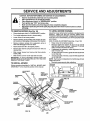
TO REMOVE MOWER (See Fig. 18)
TO LEVEL MOWER HOUSING
•
o
Place attachment clutch in "DISENGAGED" position_
Turn height adjustment knob to lowest setting°
•
Lower' mower to its lowest position.
•
Remove retainer spring holding anti-swaybar to chas*
sis bracket and disengage anti-swaybar from bracket°
°
Remove retainer' springs from suspension
deck and disengage arms from deck..
°
•
Raise attachment lift to its highest position.
Remove two retainer' springs from each front link and
remove links.
Adjust the mower whiletractor is parked on level ground or
driveway. Make sure tires are properly inflated (See
"PRODUCT SPECIFICATIONS" on page 3 ofthis manual).
If tires are over or underinflated,you will not properly adjust
your mower.
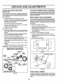
SIDE-TO-SIDE ADJUSTMENT (See Figs. 18 and 19)
•
Raise mower to its highest position.
° Measure height from bottom of deck curl to ground
level at front corners of mower. Distance "A" on both
sides of mower should be the same.
•
If adjustment is necessary, make adjustment on one
side of mower only.
To raise one side of mower, tighten lift link adjustment
nut on that side.
•
To lower one side of mower, loosen lift link adjustment
nut on that side=
NOTE: Each full turn of adjustment nut will change mower
height about 3/16".
o Recheck measurements after adjusting.
arms at
°
Slide mower forward and remove belt from electric
clutch pulley.
°
Slide mower out from under right side of tractor'.
IMPORTANT; IF AN ATTACHMENT OTHER THAN THE
MOWER DECK IS TO BE MOUNTED ON THE TRACTOR,
REMOVE THE FRONT LINKS.
TO INSTALL MOWER
BOTTOM
OF CURL
Follow procedure described in "INSTALL MOWER AND
DRIVE BELT" in the Assembly section of this manual.
ADJUSTMENT
NUTS
LIFT
LINKS
BOTTOM
OF CURL
FRONT
SUSPENSION
SUSPENSION
ARMS
FIG. 19
BRACKET
CHASSIS
LINKS
FRONT
SUSPENSION
BRACKET
RETAINER
SPRING
ANTI-SWAY
BAR
FRONT MOWER
BRACKET
RETAINER
SPRINGS
FIG. 18
20
1,1,1,1
SERVnCE AND ADJUSTMENTS
,I,ii1_,,_l_ _i,
TO REPLACE
FRONT-TO-BACK ADJUSTMENT (See Figs. 20 and 21) IMPORTANT . DECK MUST BE LEVEL SIDE-TO-SIDE. IF
THE FOLLOWING FRONT-TO-BACK ADJUSTMENT IS
NECESSARY, BE SURE TO ADJUST BOTH FRONT LINKS
EQUALLY SO MOWER WILL STAY LEVEL SIDE-TO-SIDE.
To obtain the best cutting results, the mower housing
should be adjusted so the front is approximately 1/8" to 1/2"
lower than the rear when the mower is in its highest
position.
Check adjustment on right side of tractor. Measure distance "F" directly in front of and behind the mandrel at
bottom edge of mower housing as shown.
= Before making any necessary adjustments, check that
both front links are equal in length.
o If links are not equal in length, adjust one link to same
length as other link.
•
To iowerfrontof mowerhousing, toosen nut"G"on both
front links an equal number of turns.
•
When distance "F" is 1/8" to I/2" lower at front than
rear, tighten nut"H" against trunnion on both front linkso
= To raise front of mower housing, loosen nut "H" from
trunnion on both front links, Tighten nut "G" on both
front links an equal number of turns°
°
When distance "F' is 1/8" to 1/2" lower at front than
rear, tighten nut "H" against trunnion on both front
links.
NOTE= Each full turn of nut "G" will change dim. "F" by
approximately 3/8"o
°
Recheck side-to-side adjustment,
iil,ll,,i i,,,ii,i ,ill i i i,
_,
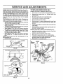
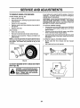
MOWER DRIVE BELT REMOVAL(See Fig° 22) ,
Park tractor on a level surface° Engage parking brake.
°
Remove four screws from LoHomandrel cover and
remove cover.
,
Roll belt over the top of L.H. mandrel pulley,
°
Remove belt from electric clutch pulley.
=
=
Remove belt from idler pulleys.
Remove any dirt or grass clippings which may have
accumulated around mandrels and entire upper deck
surface.
•
Check primary idler arm and two idlers to see that they
rotate freely.
Be sure spring is securely hooked to primary idler arm
and bolt in mower housing°
=
MOWER DRIVE BELT INSTALLATION (See Fig, 22) °
Install belt in both idlers. Make sure belt is in both belt
keepers at the idlers as shown°
•
Install new belt onto electric clutch pulley.
°
°
Roll belt into upper groove of LH. mandrel pulley°
Carefully check belt routing making sure belt is in the
grooves correctly and inside belt keepers,
Reassemble LHo mandrelcover.
•
MANDREL
LH.
MANDREL
SCREWS
IDLER
PULLEYS
MOWER
DRIVE
FIG. 20
BOTH FRONT LINKS SHOULD BE EQUAL IN LENGTH
PRIMARY
IDLER
BELT
ARM
KEEPERS
FIG. 22
TRUNNION
FIG. 21
:
MOWER DRIVE BELT
21
ELECTRIC
CLUTCH
PULLEY
S
TO REPLACE
AND ADJUSTMENTS
MOWER
BLADE DRIVE BELT
°
(See Fig. 23)
Park the tractor on level surface. Engage parking brake.
•
Remove mowerddve belt (See'TO REPLACE MOWER
DRIVE BELT" in this section of this manual).
Remove mower (See "TO REMOVE MOWER" in this
section of this manual).
°
Remove four' screws from Roll. mandrel cover and
remove cover. Unhook spring from bolt on mower
housing.
•
Carefully roll belt off R.H. mandrel pulley.
°
Remove belt from center mandrel pulley, idler pulley,
and L.Ho mandrel pulley°
•
Remove any dirt or grass which may have accumulated around mandrels and entire upper deck surface.
,
Check secondary idler arm and idler to see that they
rotate freely°
°
Be sure spring is hooked in secondary idler arm and
sway-bar bracket.
•
Install new belt in lower groove of L.Ho mandrel pulley,
idler pulley, and center mandrel pulley as shown.
= Roll belt over Roll. mandrel pulley. Make sure belt is in
all grooves properly.
,
Reconnect spring to bolt in mower housing and reinstall R.H. mandrel cover.
°
Reinstall mower to tractor (See'q'O INSTALL MOWER"
in the Assembly section of this manual).
.
Reassemble mower' drive belt (See "TO REPLACE
MOWER DRIVE BELT' in this section of this manual).
L.H,
MANDREL
MOWER
BLADE
DRIVE BELT
Make sure attachment clutch and tgnitionswitches are
in "OFF" position.
°
Adjust the three nylon locknuts until space between
clutch plate and rotor measures .012' at alt three slot
locations cut inside of brake plate.
NOTE-" After installinga new electric clutch, run tractor at
full throttle and engage and disengage electric clutch 10
cycles to wear in clutch plate.
CLUTCH PLATE
.012"
NYLON LOCKNUT (3)
BRAKE PLATE
FIG. 24
TO ADJUST
BRAKE
(See Fig. 25)
Your tractor is equipped with an adjustable brake system
which is mounted on the left side of the transaxle_
If tractor requires more than six (6) feet stopping distance
at high speed in highest gear',then brake must be adjusted.
°
•
CENTER
MANDREL
Depress clutch/brake pedaland engage parking brake.
Measure distance between brake operating arm and
nut "A" on brake rod.
tf distance isother than 1-3/4", loosen jam nut arid turn
nut "A" until distance becomes 1-3/4". Retighten jam
nut against nut "A".
IDLER
PULLEY
Road test tractor for proper stopping distance as stated
above. Readjust if necessary. If stopping distance is
still greater than six (6) feet in highest gear, further
maintenance is necessary. Contact your nearest authorized service center/department.
R_H_
MANDREL
COVER
SECOI
IDLER ARM
WITH PARKING BRAKE "ENGAGE"
SPRING
SWAY-eAR
BRACKET
SCREW
FIG. 23
TO ADJUST ATTACHMENT
(See Fig. 24)
CLUTCH
OPERATING
ARM
NUT
The electric clutch should provide years of service. The
clutch has a built-in brake that stops the pulley within 5
seconds. Eventually, the internal brake will wear' which
may cause the mower blades to not engage, or, to not stop
as required, Adjustments shouldbe made by your nearest
authorized service center/department,,
FIG. 25
22
;TMENTS
VnCE AND A
TO REPLACE
(See Fig. 26)
MOTION
DRIVE BELT
TO ADJUST STEERING
If steering wheel crossbars are not horizontal (left to right)
when wheels are positionedstraightforward, remove steering wheel and reassemble per instructions in the Assembly
section of this manual°
Park the tractor on level surface. Engage parking brake.
Forease of service there is a belt installationguide decal on
bottom of leftfootrest, itis not necessaryto remove mower,
BELT REMOVAL •
Engage parking brake (creates slack in belt)_
°
Remove mower drive belt from electric clutch pulley
only (See TO REPLACE MOWER DRIVE BELT" in
this section of this manual)°
Roll motion drive belt off transaxie pulley°
•
FRONT WHEEL TOE-IN ADJUSTMENT
Frontwheel toe-in is required for propersteering operation,,
Toe-in ,wasset at the factory and adjustment should not be
necessary, If parts in the front axle or steering mechanism
have been replaced or damaged, check toe-in and adjust
if necessary.
TO CHECK TOE-IN (See Fig,,27) ° Position front wheels straight ahead°
° Measure distance between wheels at front and rear of
tires (dimensions "A" and "B").
°
Front dimension "A" should be 1/8" to 1/4" less than
rear dimension "B".
°
Roll belt off clutching idler pulleys, then off engine
pulley and front V-idler pulley.
°
Pull belt out of all belt keepers.
BELT INSTALLATION o
=
Place V part of belt into grooves on engine pulley and
front V-idler, making sure to route belt inside of belt
keepers_
Put belt coming from V-idler above mldspan belt keeper,
then onto clutching idler pulleys as shown.
•
Make sure V part of belt engages V-idler.
•
Place belt around transaxle pulley, beginning at top.
V part of belt should engage transaxle pulley.
TO ADJUST TOE-IN (See Figs. 27 and 28) .
Loosen jam nuts at adjustment sleeves on tie rod_
°
Adjust tie rodunti]dimension "A" is 1/8" to 1/4" less than
dimension "B".
•
Tighten jam nuts securely.
=
Place long lowersection of belt through loop in midspan
belt keeper_
° Check to be sure belt is on proper side of all belt
keepers°
°
Reinstall mower drive belt onto electric clutch pulley.
IMPORTANT: CHECK BRAKE ADJUSTMENT.
B
CLUTCHING
IDLER
\
_.
FRONT OF TRACTOR
TRACTOR V-BELT DRIVE SCHEMATIC
VIEWED FROM L.H° SIDE OF TRACTOR
CLUTCHING
FLATIDLER
WHEEL ALIGNMENT
FIG. 27
BELT
ADJUSTMENT
SLEEVES
ENGINE
PULLEY
V-IDLER
BELT
KEEPER
BELT
TWISTS
BELT
KEEPER
TRANSAXLE
PULLEY
JAM NUTS
FIG. 28
AS VIEWED FROM BOTTOM
FRONT WHEEL CAMBER
FIG. 26
The frontwheel camber is not adjustable on your tractor. If
damage has occurred to affect the front wheel camber,
contact your nearest authorized service center/depart_
menL
23
EAND A
:.....
t ,,ti,
till,
_:
TO REMOVE WHEEL FOR REPAIRS
If your battery is too weak to start the engine, it should be
recharged°
If "jumper cables" are used for emergency
starting, follow this procedure:
IMPORTANT: YOUR TRACTOR iS EQUIPPED WITH A 12
VOLT NEGATIVE GROUNDED
SYSTEM.
THE OTHER
VEHICLE
MUST ALSO BE A 12 VOLT NEGATIVE
GROUNDED SYSTEM. DO NOT USE YOUR TRACTOR
BATTERY TO START OTHER VEHICLES°
FRONT WHEEL (See Fig. 29) •
Block up axle securely.
,
Removeaxlecover,
wheel removal.
retaining ringandwasi_erstoaltow
•
Repair tire and reassemble.
°
Replace washers and snap retaining ring securely in
axle groove°
•
Replace axle cover.
TO ATTACH JUMPER CABLES • Connect each end of the RED cable to the POSITIVE
(+) terminal of each battery, taking care not to short
against chassis.
•
Connect one end of the BLACK cable to the NEGATIVE (-) terminal of fully charged battery.
REAR WHEEL =
Block rear axle securely.
°
°
Remove five (5) hub bolts to allow wheel removal.
Repair' tire and reassemble. Replace and tighten hub
bolts securely.
•
NOTE: To seal tire punctures and prevent flat tires due to
slow leaks, tire sealant may be purchased from your local
parts dealer. Tire sealant also prevents tire dry rot and
corrosion,
Connect the other end of the BLACK cable to a panel
bolt on the left side of the tractor, away from fuel tank
and battery.
TO REMOVE CABLES, REVERSE ORDER o
°
BLACK cable first from chassis and fully charged
battery.
•
RED cable last from both battedes_
WASHERS
RETAINING
RING
AXLE
COVER
FIG. 29
TO START
ENGINE
WITH
A WEAK
BATTERY
(See Figs. 30)
BOLT
PANEL
CAUTION:
0 !
Lead-acid batteries gener-
and smoking materials away from batateexplosivegases.
Keep
sparks,
flame
teries.
Always wear
eye
protection
when around batteries.
FIG, 30
24
........................
SERVHCE
TO REPLACE
HEADLIGHT
Raise hood.
Pull bulb holder out of the hole in the backside of the
grill.
°
Replace bulb in holder and push bulb holder securely
back into the hole in the backside of the grill,,
Close hood.
°
INTERLOCKS
ADJUSTMENTS
BULB
•
•
ADJUSTMENT
Replace with 30 amp automotiveotypeplug-in fuse° The
fuse holder is located behind the dash.
LIFT SPRING
•
While holdingspring bushing with wrench, loosen jam
nut.
°
Turn adjustment bolt clockwise to extend spring and
reduce lift effort (for heavier attachments)°
Turn adjustment bolt counterclockwisefor lighter attachments.
°
ATTACHMENT
LIFT SPRING
/
TO REMOVE HOOD AND GRILL ASSEMBLY
(See Fig. 32)
FUSE
TO ADJUST ATTACHMENT
(See Fig. 31)
NUT
FIG. 31
Check wiring° See electrical wiringdiagram in Repair
Parts section of this manual
TO REPLACE
SPRING BUSHING
JAM
AND RELAYS
Loose or damaged wiring may cause your tractor to run
poorty,stop running, or prevent it from starting.
o
....._..i,,i ,
°
Raise hood.
.
°
Unsnap headlight wire connector,
Stand infront oftractor. Grasp hood at sides, tilt toward
engine and lift off of tractor.
°
To replace, reverse above procedure,
HEADLIGHT
WIRE
CONNEC_ON
•
Retighten jam nut against spring bushing.
IMPORTANT: DO NOT ADJUST FOR MAXIMUM SPRING
TENSION WHEN USING LIGHT ATTACHMENTS SUCH
AS A MOWER° ADJUST LIFT LEVER SPRING TO AID IN
LIFTING ATTACHMENT. DO NOT OVERPOWER SPRING.
WHEN REMOVING ATTACHMENT, ALWAYS ADJUST
SPRING TENSION TO ITS LOWEST POSITION°
HOOD
FIG, 32
25
AND ADJ
ENGINE
TO ADJUST THROTTLE
(See Fig. 33)
CONTROL
TO ADJUST CHOKE CONTROL
(See Figs. 33 and 34)
CABLE
The choke control has been preset at the factory and
adjustment should not be necessary, check adjustment as
described below before loosening cable. If adjustment is
necessary, proceed as follows:
The throttle control has been preset at the factory and
adjustment should not be necessary° Check adjustment as
described below before loosening cable. If adjustment is
necessary, proceed as follows:
•
.
With engine not running, move throttle control lever to
fast position.
Checkthat speed control lever is against stop screw. If
it is not, loosen casing clamp screw and pull throttle
cable until lever is against screw. Tighten clamp screw
securely.
IDLE FUEL
ADJUSTING
NEEDLE
ENTS
•
With engine not running, move choke control (located
on dash panel) to full choke position.
•
Remove air cleaner cover, filter and cartridge plate to
expose carburetor choke (See "AIR FILTER" in the
Customer Responsibilities section of this manual).
°
Choke should be closed, if it is not, loosen casing
clamp screw and move choke cable until choke is
completely closed_ Tighten casing clamp screw securely.
Reassemble air cleaner.
•
IDLE SPEED
ADJUSTING
SCREW
CLOSED FOR
FULLCHI
THROTTLE
CONTROL
CABLE
FIG. 34
STOP
SCREW
CLAMP
SCREW
CHOKE
CONTROL
CABLE
FIG. 33
26
$ERWCE
TO ADJUST
CARBURETOR
AND ADJUSTMENTS
(See Fig. 33)
The carburetor has been present at the factory and adjustment should not be necessary. However, minor adjustment
may be required to compensate for differences in fuel,
temperature, altitude or Ioado If the carburetor does need
adjustment, proceed as follows:
In general, turning the adjusting needles in (clockwise)
decreases the supply of fuel to the engine giving a leaner
fuel/air mixtureo Turning the adjusting needles out (counterclockwise) increases the supply of fuel to the engine
giving a richer fue!/air mixture.
IMPORTANT: DAMAGE TO THE NEEDLES AND THE
SEATS IN CARBURETOR MAY RESULT IF SCREW IS
TURNED IN TOO TIGHT.
PRELIMINARY SETTING
,
The high idle is set at the factory and cannot be
adjusted.
°
Idle fuel needle setting _With throttle control lever in
slow position, turn idle fuel adjusting needle in (clockwise) until engine speed decreases and then turn out
(counterclockwise) approximately 3/4 turn to obtain the
best low speed performance..
=
Be sure you have a clean air filter, and the throttle
control cable is adjustedproperly (see "TO ADJUST
THROTTLE CONTROL CABLE' in the Service and
Adjustments section of this manual).
o With engine off turn idlefuel adjusting needle in (clockwise) closing it finger tight and then turn out (counterclockwise) 1 turn°
FINAL SETTING Start engine and allow to warm for five minutes_ Make
final adjustments with engine running and shift!motion
control lever in neutral (N) position_
Idle speed setting - With throttle control lever in slow
osition, engine should idle at 1200 RPM. If engine
Ies too slow or fast, turn idle speed adjusting screw in
or out until correct idle is attained°
° Recheck idle speed° Readjust if necessary°
ACCELERATION TEST -
•
=
•
Move throttle control lever from slow to fast position. If
engine hesitates or dies, turn idle fuel adjusting needle
out (counterclockwise) 1/8 turn. Repeat test and continue to adjust, if necessary, until engine accelerates
smoothly.
High speed stop is factory adjusted, Do not adjust-damage
may resulL
IMPORTANT:
NEVER TAMPER WITH THE ENGINE
GOVERNOR,
WHICH iS FACTORY SET FOR PROPER
ENGINE SPEED. OVERSPEEDING
THE ENGINE ABOVE
THE FACTORY
HIGH SPEED
SETTING
CAN BE
DANGEROUS._ IF YOU THINK THE ENGINE-GOVERNED
HIGH SPEED NEEDS ADJUSTING,
CONTACT
YOUR
NEAREST
AUTHORIZED
SERVICE
CENTER/
DEPARTMENT, WHICH HAS PROPER EQUIPMENT AND
EXPERIENCE
TO
MAKE
ANY
NECESSARY
ADJUSTMENTS,.
27
STORAGE
ENGINE
Immediately prepare your tractor for storage at the end of
the season or if the tractor will not be used for 30 days or
more.
FUEL SYSTEM
IMPORTANT:
IT IS IMPORTANT
TO PREVENT GUM
DEPOSITS
FROM FORMING
IN ESSENTIAL
FUEL
SYSTEM PARTS SUCH AS CARBURETOR, FUEL FILTER,
FUEL HOSE, OR TANK DURING STORAGE.
ALSO,
EXPERIENCE
INDICATES THAT ALCOHOL BLENDED
FUELS (CALLED GASOHOL OR USING ETHANOL OR
METHANOL) CAN ATTRACT MOISTURE WHICH LEADS
TO SEPARATION AND FORMATION OF ACIDS DURING
STORAGE,
ACIDIC GAS CAN DAMAGE THE FUEL
SYSTEM OF AN ENGINE WHILE IN STORAGE_
gasoline in the tank inside a building
where
fumes
may store
reachthe
an tractor
open flame
CAUTION:
Never
with
or spark. Allow the engine to cool
before storing in any enclosure.
TRACTOR
Remove mower from tractor for winter storage. When
mower is to be stored for a period of time, clean it thoroughly, remove aft dirt, grease, leaves, etc. Store in a
c|ean, dry area.
•
Clean entire tractor (See"CLEANING"in the Customer'
Responsibilities section of this manual).
•
Inspect and replace belts, if necessary (See belt replacement instructions in the Service and Adjustments
section of this manual).
•
Lubricate as shown in the Customer Responsibilities
section of this manual.
°
Be sure that all nuts, bolts and screws are securely
fastened. Inspect moving parts for damage, breakage
and wear. Replace if necessary,
Touch up all rusted or chipped paint surfaces; sand
lightly before painting.
•
Fully charge the battery for storage.
After a period of time in storage, battery may require
recharging.
•
To help prevent corrosion and power leakage during
long periods of storage, battery cables should be
disconnected and batten]cleaned thoroughly (see "TO
CLEAN BATTERY AND TERMINALS' in the Customer Responsibilities section of this manual)°
Drain the fuel tank.
•
Start the engine and let it run until the fuel lines and
carburetor are empty.
Never use engine or carburetor cleaner products in the
fuel tank or permanent damage may occur.
Use fresh fuel next season.
•
°
NOTE: Fuel stabilizer is an acceptable alternative in
minimizing the formation of fuel gum deposits during storage. Add stabilizerto gasoline in fuel tank or storage
container. Always follow the m_x ratio found on stabilizer
container. Run engine at least 10 minutes after adding
stabilizer to allowthe stabilizer to reach the carburetor, Do
not drain the gas tank and carburetor if using fuel stabilizer.
ENGINE OIL
Drain oil (with engine warm) and replace with clean engine
oil
(See "ENGINE" in the Customer Responsibilities
section of this manual).
BATTERY
•
°
•
CYLINDERS
,
Remove spark plug(s).
•
Pour'one ounce of oil through spark plug hole(s) into
cylinder(s).
°
Turn ignition key to"START" positionfor a few seconds
to distribute oi!,
•
Replace with new spark plug(s),
°
After cleaning, leave cables disconnected and place
cables where they cannot come in contact with battery
terminals.
•
Be sure battery drain tube is securely attached.
=
°
If battery is removed from tractor for storage, do not
store battery directly on concrete or damp surfaces.
•
OTHER
Do not store gasoline from one season to another.
Replace your gasoline can if your can starts to rust,
Rust and/or dirt in your gasoline wilt cause problems,
°
If possible, store your tractor'indoors and cover it to
give protection from dust and dirt=
° Cover yourtractor with a suitable protective cover that
does not retain moisture, Do not use plastic, Plastic
cannot breathe which allows condensation to form and
will cause your tractor to rust.
IMPORTANT: NEVER COVERTRACTOR WHILE ENGINE
AND EXHAUST AREAS ARE STILL WARM,
28
POHNTS
TROUBLESHOOTING
PROBLEM
CAUSE
CORRECTION
Will not start
t.
2,,
3.
4.
5,,
6o
7,
Out of fuel,,
Engine not "CHOKED" properly,
Engine flooded.
Bad spark plug,
Dirty air fitter,,
Dirty fuel filter.
Water in fuel
2.
3o
4.,
5°
6.
7.
8.
9.
Loose or damaged wiring,
Carburetor out of adjustment,
8,
9-
10.
Hard to start
Engine will not turn over
1.. Fill fuel tank,,
Engtne valves out of adjustment,
See "TO START ENGINE" tn Operation section.,
Wait several minutes before attempting to sled,
Replace spark plug.
Clean/replace air fitter.
Replace fuel fitter,,
Drain fuel tank and carburetor, refill tank with fresh
gasoline and replace fuel fitter.
Check eli wiring,
See "To Adjust Carburetor" tn Service Adjustments
section,
t0o
Contact an authorized service center/department.,
!.
2,,
3,,
4.
5.
6.
7.
Dirt,] air filter.
Bad spark plug,,
Weak or dead battery.
Dirty fuel filter.,
Stale or dirty fuel.
Loose or damaged wiring,
Carburetor out of adjustment.
1.
2.
3_
4.
5.
6,
7.
Clean/replace air filter,,
Replace spark plug,
Recharge or replace battery,
Replace fuel filter°
Drain fuet tank and refill with fresh gasoline.
Check el! wiring.
See "To Adjust Carburetor" In Service Adjustments
section,,
8o
Engine valves out of adjustment,.
8
Contact an authorized service center/department.
1_
2.
3,
4,,
Clutch/brake pedal not depressed
Attachment clutch ts engaged.
Weak or dead battery.
Blown fuse.
5_
6,
7_
8,
9..
Corroded battery termlnats_
Loose or damaged wiring,
Faulty ignition switch.
Faulty solenoid or starter°
Faufty operator presence switch(as),
1.
2.
3,
4.,
5.
6.
7_
8,
9..
Depress clutcl-ffbrake pedal.
Disengage attachment clutch,
Recharge or reptace battery°
Replace fuse°
Clean batterytermtnals,
Check all wiring,
ChecPJraplace Ignition switch,
Check/replace solenoid or starter_
Contact an authorized service center/department,
Recharge or replace battery°
Clean battery termlnalso
Check all wiring,,
CheckJreplace solenold or stader,,
Engine cltcks but will not
start
1. Weak or dead battery_
2o Corroded battery terminals.
3o Loose or damaged wiring.
4_ Faulty solenoid or starter..
1.
2.
3,
4.
Loss of power
1.
2.
3.
4.
5.
6.
7,,
8.
9,
1_
2_
3,
4.
5.
6,
7,
8,
9-
Cutting too much grass/too fast.,
Throttle tn "CHOKE" position.
Build-up of grass, leaves and trash under mower,
Dirty air filter.
Low oil leve!/dirty oIL
Faulty spark plug,
Dkty fuel fflter_
State or dirty fuel
Water In fuel
10.
! 1.
12_
t3,
I4
Spark plug wireloose.
Dirty engine afr screen/fins.
Dirty/clogged muffler,.
Loose ordemaged w[ring_
Carburetor out of adjustmenL
15,,
Engtne valves out of adjustmenL
Set In "Higher Cut" position/reduce speed.
Adjust throttle control.
Clean underside of mower housing
Clean/replace air filter.
Check oil level/change oil
Clean and regap or change spark plug,
Replace fuel filter.
Drain fuel tank and reliJlwith fresh gasoline,,
Drain fuel tank and carburetor, refill lank with fresh
gasoline and replace fuel fitter_
I 0o Connect and lighten spark ptug wire.
11,, Clean engine atr screen/tins,,
12. Ciean/raplace muffler
13. Check all wiring.
14. See "To Adjust Carburetor" in Service Adjustments
section,
15. Contact an authorized service center/departmento
JIIIILILILIUIJ/Jl
IlJl/J/
IIII
Excessive vibration
1o
2,
3.
Worn, bent or loose blade.
Bent blade mandrel.
Loose!damaged pad(s),
1.
2,
3.
29
Replace blade_, Tighten blade bolt.
Replace blade mandrel.
Tighten loose part(s),, Replace damaged parts_
TROUBLESHOOTING
ill lllllll,
PROBLEM
i
lllll
POINTS
i
CAUSE
N,
ii
ii ill
ij
i
.
llll
CORRECTION
,
,, ,,,,,,,
,,,,,,
.....
,,,
,_,,,,
,,,
,,,,
_,,,,,,
,
i
N,
ill
llllllll
llll
m ill
L ill,ill,
Engine continues to run
when operator leaves seat
with attachment clutch
engaged
1, Faulty operator-safety presence control system,.
1,
Check wiring, switches and connecttons_ Ifnot
corrected, contact an authorized service center/
dapartment_
Poor cut - uneven
I. Worn, bent or loose blade.
2, Mower deck not level.
I,
2.
3.
4.
5.
Replace blade. Tighten blade bolt,
Level mower deck.
Clean underside of mower housing.
Replace blade mandrel,
Clean around mandrels to open vent holes.
1,
2,
3.
4.
Remove
Replace
Replace
Replace
3.
4,
5,
Buildup of grass, leaves, and trash under mower_
Bent blade mandrel,
Clogged mower deck vent holes from buildup ef
grass, leaves, and trash around mandrels
Mower blades wUI not
rotate
1.
2.
3.
4,
Obstruction in clutch mechanism
Worn/damaged mower drive belt
Frozen idler pulley.
Frozen blade mandreL,.
Poor grass discharge
i,
2.
3_
4,
Engine speed too slow.
Travel speed too fast
Wet grass,_
Mower deck not level.
5,
6_
7.
8,
Lowluneven tire air pressure.
Worn, bent or loose blade,.
Buildup of grass, leaves and trash under mower
Mower drive belt worn.
9.
10r
11.
Blades tmpropedy Installed,
Improperb!ades used.
Clogged mower deck vent holes from buildup of
grass, leaves, and trash around mandrels,
Headlight(s) not working
(if so equipped)
Battery will not charge
Englne "backfires"
when turning engine
"OFF"
ii.,
obstruction.
mower drivebelt.
Idler
pulley,
blade mandrel,
PlacethrottlecontrolIn "FAST"posi_on,.
Shift tosIowerspeed,
3
Allow grassto drybeforemewing,
4. Levetmower deck,
5,. Checktiresfor properatr pressure.
6.
Replace/sharpen
blade. Tighten bladebolt,
7. Cleanundersideof mowerhousing.
8, Replacemowerdrivebell
9, RelnstaJl
blades sharpedgedowm
10 Replacewithblades listed in thismanual,
11. Cleanaround mandrelsto openventholes,
2,.
t.
Switch is "OFF",
1,.
Turn switch "ON"
2.
3
4.
5,
Bulb(s) burned out
Faulty light switch,
Loose or damaged wiring,
Blown fuse,
2,
3.
4.
5_
Replace bulb(s).
Checldraplace light switch.
Check w[dng and connections_
Replace fuse_
1,
Replace battery.
Check/clean all connect{ons.
Replace regulator.
Replace alternator,
1° Bad battery cell(s).
2. Poor cable connections.
2.
3,
4.
Faulty regulator (if so equipped),
Faulty a|temator°
3,*
1
Engine throttle control not set at "SLOW"
position for 30 seconds before stopping engine
1,
4.
30
Move throttle control to "SLOW" position and aflow
to idle for 30 seconds before stopping engine.
TRACTOR - MODEL NUMBER 917.258863
SCHEMATIC
RED
l
l
(OPTIONAL)
IGNMON
SWITCH
q
NOTE
YOUR TRACTOR IS
EQUIPPED WITH A SPECIAL
ALTERNATOR SYSTEM
THE LIGHTS ARE NOT
CONNECTED TO THE
RELAY
HEADLIGHTS
G F C
BATTERY, BUT HAVE THEIR
OWN ELECTRICAL SOURCE,
PTO SWITCH
BECAUSE OF THIS, THE
BRIGHTNESS OF THE LIGHTS
OFF
C+G,B+H
WiLL CHANGE WITH ENGINE
ON
C+F, B+E+A+D
SPEED+ AT IDLE THE LIGHTS
DA
WILL DIM, AS THE ENGINE IS
©
tt
SPEEDED UP, THE LIGHTS
WILL BECOME THEIR BRIGHTEST,
REMOVABLE
NON-REMOVABLE
_o%o, .........
cmcuiT
IGNITION SWITCH
POSITION!
CIRCUIT
"MAKE"
OFF
RUNiUGH-[
G+ M + L
B+ L
NOllE
A + Y
RUN
B +L
NONE
START
B+L + S
NONE
WIRING INSULATED CLIPS
NOTE: IF WIRING INSULATED
CLIPS WERE REMOVED FOR
SERVICING OF UNIT, THEY
SHOULD BE REPLACED TO
PROPERLY SECURE YOUR
WIRING
CONNECTIONS
ENGINE CONNECTOR
REGULATOR
_
(PURPLE WIRE+ \
RED WIRE)
CARBURETOR
SOLENOID
(RED WIRE,
BLUE WIRE)
F
/
ENGINE
SHORTING
_
(WHITE WIRE)
lf____J1c3Gll
1f_tI
.J_L--_f
OIL SENTRY
_'_ _
_" (GREEN WIRE)
31
H
OEIt
IB
CONNECTIONS
TRACTOR CONNECTOR
IGNITION SWITCH
"M" FOR ENGINE "_
BATTERY
CHARGING
(BLACKWIRE)SHORTING
ll_
_]_
OILSENTRYII _-t
_
OPTION
_
(YELLOW WIRE
TO LIGHT PKG )
u---,-_
I1 (RED WIRE)
Ii SWITCHED
+12V
t_LUE WIRE)
REPAIR PARTS
TRACTOR
- - MODEL
NUMBER
917.258863
ELECTRICAL
22
4O
19
33
2O
32
31
t
I
I
I
I
1
25
t
I
I
!
I
I
I
I
I
I
I
l
I
11
I
1
I
I
t
|
\
I
I
\
J
I
I
,
|
I
/
t
t
I
I
/
I
|
51
/
\
t
Il
/
/
,,
i
/
x/
I
J 26
I
i
!
I
I
I
!
I
I
12 t
I
29
't
\
\
\
-r
I
I
I
1
!
jP
I
x
32
REPAIR PARTS
TRACTOR
-- MODEL
NUMBER
917.258863
ELECTRICAL
KEY
NO.
PART
NO.
1
2
3
4
6
8
10
11
12
16
19
20
21
22
24
25
26
28
29
30
31
32
33
40
41
42
43
45
50
51
52
8t
144927
74760412
STD551125
STD551025
STD541025
7603J
145211
150109
145769
153664
STD551125
73350400
136850
4152J
4014J
146686
108824X
157899
160784
140301
124211X
141226
109310X
160732
17720408
131563
145673
122822X
154963
140405
141940
I09748X
DESCRIPTION
Battery
Bolt Hex Head 1/4-20 x 3/4
Washer, Lock 1/4
Washer 9/32 x 5/8 x 16 Ga
Nut Fin Hex 1/4-20
Tray, Battery
Bolt 1/4-20 x 7.5 Zinc
Hold down Battery Dash Mount
Nut Push Nyton 1/4"
Switch Interlock Push-ln
Washer, Lock 1/4
Nut, Jam Hex 1/4-20
Harness Socket Light Wi4152J
Bulb Light
Cable, Battery
Cable, Battery
Fuse
Cable, Ground
Switch, Plunger
S_vitch, lgn
Nut, Ignition Switch
Cover Switch Key
Key, Ignition
Harness lgn.
Screw 114-20 x 1/2
Cover, Terminal
Solenoid
Ammeter
Switch, PTO
Ring Retainer PTO
Protection Wire Loop
Relay Asm.
NOTE: All component dimensions given in U.S inches
1 inch = 25°4 mm
33
REPAIR PARTS
TRACTOR--
MODEL NUMBER 917.258863
CHASSIS AND ENCLOSURES
18
38
59
11
92
47120
56
91
,
17
19
67
86
34
15
REPAIIR PARTS
TRACTOR
- .. MODEL
NUMBER
917,258863
CHASSIS AND ENCLOSURES
KEY
NOo
1
2
3
4
5
6
7
8
9
10
11
12
13
14
15
16
I7
18
19
20
21
22
23
24
28
29
30
31
32
33
34
35
36
37
38
39
PART
NO.
150253
140506
136671X558
73800700
145203
157882
17720408
145166
108067X
19092016
t37270
t37269
t37271
136673X558
136374
121794X
17490612
136373X428
19131312
STD523710
STD541437
136670X558
17490616
145243X558
I45244X558
145349
145051X014
161419
141315
141314
142131
19111116
74780512
t21642X558
19091216
136961
DESCRIPTION
KEY
NO.
Rail, Frame RH
Drawbar, Gt
PanelAsmo, Side LH
Nut, Lock Hex 7/16 Unc
Dash, Plastic Black
Dash, Lower Vgt One Piece
Screw, Thd Cut 1/4-20 x 1/2
Support, Battery
Nut, Pal
Washer 9/32 x 1-1/4 x 16 Gao
Rivet, Ratchet Male
Washer, Nylon
Rivet, Ratchet Female
Hood Asm., Pnt
Lens, Bar Clear
Cover, Access
Screw, Thdrol 3/8-16 x 3/4
Gdlle
Washer 13/32x 13/16 x 12 Ga.
Bolt, Fin Hex 3/8-16 x 1
Nut Crownlock 3/8-16 Unc
Panel Asm., Side RH
Screw Thdrol 3/8-16 x 1 Ty-Tt
Footrest, RH
Footrest, LH
Bracket, Support Dash
Saddle, Slkscr Vgt
Brace, Supt 1-pc VGT Steering
BracketAsm., Frame PivotLh
Bracket Asm., Frame Pivot Rh
Bracket, Engine Support Rear
Washer 11/32x11/16x16Ga_
Bolt, Fin Hex 5/16-18 x 3/4
Fender, Pnto
Washer 9/32x3!4x
16 Gao
Bracket, Axle Front
40 156111
Bracket, Support Axle/Engine
42 72140608
Bolt, Carriage 3/8-16 x 1
43 136939
Bracket, Spnsn Front Lh
44 136940
Bracket, Spnsn Front Rh
45 154913
Bracket Asm., Susp Chassis Rh
Screw Thdrol. 3/8-16 x 1/2
47 17490608
48 157105
Bracket Asm., Pivot Hood Lh
49 157107
Bracket Asm, Pivot Hood Rh
50 152728
Bracket, Chassis Front
52 STD541431
Nut, Crownlock 5116-18 Unc
56 155914
Bracket Asm., Susp Chassis Lh
57 73640400
Nut, Keps, Blk Hex 1/4-20 UNC
58 137113
Bracket Asm., Fender
59 741804!2
Screw, Mach Cr 1/4-20 x 3/4
60 17490620
Screw Thdrol. 3/8-16 x 1-1/4
Washer 13/32 x 1 x 14 Ga.
63 19131614
64 144283
Washer, Serrated Disc 13/32 x 1
67 156793
Guide, Belt Gear Drive
68 17490508
Screw ThdroL 5/16-18 x I/2
70 137159
Guide, Belt Mid Span
84 142992
Stop, Over Center Mower
85 144911
Bracket, Support Transaxle
Bolt Fin Hex 7/!6-14 UNC x 1
86 74760716
88 STD551143
Washer, Lock Hvy Hlcl Spr 7/16
90 STD55t237
Washer, Lock External Tooth 3/8
Rail, Frame Lh
91 156586
92 156281X011
Plate, Silkscreen Dash
94 100207K
Clip, Fuel Line
95 105531X
Push Nut, Nylon
106 138776
Screw, Thdrol Hex Head Zinc Mwr
Washer 13/32 x I x 16 Ga.
120 19131616
130 17521312
Screw Sftd Hex Hd W/PIn Washer
137 74780616
Bolt Fin Hex 7/16-14 x 1 Gr, 5
-8022J
Plu.clrHole
NOTE: All component _hmensions given in U.S. inches
1 inch = 25.4 mm
35
PART
NO.
DESCRIPTION
REPAIR PARTS
TRACTOR
- - MODEL
NUMBER
917.258863
GROUND DRIVE
40
39_
41
42_
I
15
47
.,_
48
48
54
66
57
22
24
67
25
/
7
4
69
3
12
62
36
5
REPAIR PARTS
TRACTOR
- - MODEL
NUMBER
917.258863
GROUND DRIVE
KEY
NO.
PART
NO.
1
3
4
5
6
7
8
9
10
11
12
13
'14
t5
16
17
18
19
21
22
23
24
25
26
27
9858M1
7563R
17490508
STD541437
STD5612t0
149176
12000034
140080
142509
136927
73750800
139419
138901
8TD551037
143012
126909X
137104
136926
23260412
633A109
106932X
136925
136923
137552
17490528
28
29
30
34
35
36
73350600
137213
19131616
124236X
137648
149412
DESCRIPTION
Key, Woodruff
Washer, Thrust, Axle
Screw Thdrol 5/16-18 x 3/4
Nut, Crownlock 3/84 6
Pin, Cotter
Wheel, Hub Assembly
Klip, Ring
Bolt, Hub
Disc, Brake
Yoke, Brake Disc
Nutlock 1/2-20 Unf
Washer, Special
Bushing
Wahser 13/32x 13/16 x t6 Ga.
Set, Screw 1/4-28 x 3/4
Spring
Lever, Brake
Cam, Brake Disc
Screw, Fiat Head 1/4-28 x 3/4
Gearshift, Lever Assembly
Knob
Support, Puck Brake
Puck, Brake Top
Spring, Return
Screw, Hex Wsh Th&
5/16-18x 1-3/4
Nut, Hex Jam 3/8-16
Brake, Rod
Washer 13/32 x 1 x 16 Ga.
Cap, Plunger
Rod, Parking Brake
Spring, Drive Ground
KEY
NO.
PART
NO.
37
38
39
40
41
42
46
47
48
50
51
52
53
54
55
56
57
59
60
61
62
63
64
65
66
67
68
69
117
121749X
150035
74321016
5304J
73661000
8883R
145170
138228
72110612
131494
STD541437
139123
207J
156563
105706X
137153
141756
122253X
122268X
137524
8TD551143
74760720
154752
67609
140296
19131312
5142H
136327
73900600
NOTE:
37
DESCRIPTION
Washer 25/32 x 1-1/4 x 16 G&
Nyliner
Screw, Fin. #10-24 x 1
Actuator, Interlock Switch
Locknut #10-24
Cover, Pedal
Retainer, Spring
Clutch Rod
Boft, Carriage 3/8-16 x 1-1/2 Gr. 5
Pulley, Idler, Flat
Nut, Crownlock 3/8-16 UNC
Pulley, idler, Grooved
Washer, Hardened
Clutch, Arm Assembly
Bearing, Idler
V-Belt
Bracket, Shift Rod, HI-Lo
Shift Rod, Hi-Lo
Spring Clip, Connecting Link
Pulley, Transaxle
Washer, Lock 7/16
Bolt, Fin Hex 7/16-14 x 1-1/4
Shaft, Clutch/Brake Pedal
Bolt, Shoulder
Washer, Hardened
Washer, Flat
Pin, Roll
Hub, Cover
Nut, Lock Fig. 3/8-16 Unc
All component dimensions given in U.S. inches
1 inch = 25.4 mm
REPAIR PARTS
TRACTOR
STEERING
- - MODEL
NUMBER
ASSEMBLY
21
14
2O
23
22
31
34
33
32
6
27
42
19
27
6
/
1
1
1
/
/
16
/
\
\
15
\
_
35
14
18 ,....__
38
917.258863
REPAIR PARTS
TRACTOR
STEERING
- - MODEL
NUMBER
917.258863
ASSEMBLY
KEY
NO.
PART
NOo
1
2
3
4
5
6
7
8
9
10
11
12
13
14
15
16
17
121472X
137094
6855M
161849
161848
6266H
121748X
12000029
121232X
74781O44
136518
73901000
121749X
STD551137
STD541537
145103
137347
18
19
20
21
22
23
24
25
26
27
26
29
30
31
32
33
34
35
36
37
38
39
40
41
42
137155
156011
145182
1007tlL
155105
152927
19133808
STD523710
126805X
3366R
17490612
t04239X
12000034
138136
19111610
STD551131
STD523107
138059
137156
73360600
109850X
73700600
109851X
155246
17490508
DESCRIPTION
Wheel, Steering
Axle Asm. Front
Fitting, Grease
Spindle Asm, LH
Spindle Asm. RH
Bearing, Race Thrust Harden
Washer 25/32 x 1-5/8 x 16 Ga.
Ring, Ktip #T5304_75
Cap, Spindle
Bolt, Fin Hex 5/8-11 x 2-3/4
Spacer Bearing Axle Front
Nut, Lock Flange 5/8-! 1 Unc
Washer 25/32 x 1-1/4 x 16 Ga.
Washer, Lock Hvy Hlcl Spr 3/6
Nut, Lock Center 318-24 UNF
Shaft Asm., Steering
Rod Asm., Tie Ball J Ball Vgt (lnCo
Key No. 36-40)
Draglink, Ball Joint Solid Vgt
Support Asm., Steering Vgt
Column, Steering
Adapter, Wheel Steering
Bushing, Strgo BIk
Screw
Washer 13/32 x 2-3/8 x 8 Gao
Bolt, Fin Hex 3/8-16 x I Gro 5
Cap, Wheel Steering
Bearing, CoL Strg.
Screw, Thrdrol 3/8-16 x 3/4
Bearing, Flange
Ring, Klip Truarc #5304-75
Bushing, Nyliner Snap
Washer 11/32 x I x 10 Ga.
Washer, Lock Hvy Hlcl Spr 5/t6
Bolt, Hex Hd 5/t6-18 x 3/4
Gear, Sector Steering
Tie Rod
Jam Nut RH Thread
Joint Asmo Ball RH Thread
Jam Nut LH Thread
Joint Asm. Ball LH Thread
Bracket Switch Interlock VGT 97
Screw Thdrol 5/16_18 x 1/2 Tyt
NOTE: All component dimensions given in U.So inches
1 inch = 25.4 mm
39
REPAIR PARTS
TRACTOR - - MODEL NUMBER 917.258863
ENGINE
39
63
19
7
11
41
18
15
42
43
©
33
54
38
29
16
8
26
40
40
\
spARK
AR.ES'T_RK,
REPAIR PARTS
TRACTOR
-- MODEL
NUMBER
917,258863
ENGINE
KEY
NO.
PART
NO.
2
5
7
8
9
10
11
12
15
16
17
18
19
161062
13200300
151396
t21361X
150828
105432X
140923
143996
151346
109227X
t06082X
161493
13290300
20
21
22
23
24
25
26
27
28
29
33
37
38
39
40
41
42
43
45
47
48
50
51
53
54
55
64
65
74
162147
17720410
132779
19132616
STD551237
73920600
3645J
139277
7834R
132920
STD541437
123487X
74780624
17490636
17490664
126197X
STD551143
*150280
128861
'142040
19132007
161862
161230
161829
19131414
13280336
"17490612
19131614
162295
DESCRIPTION
Engine (See Breakdown)
Kohler Model No, CV20PS-61555
Muffler Side 1-1/8" 98
Elbow STD 90 Degree 3/8 - 18 NPT
Muffler Asm Guard
Pulley V-Idler
Keeper Asm. Belt Engine
Bushing
Clutch Electric
Pulley Engine VGT Elect Clutch
Tank Fuel Rear 3.50 Yt/Gt 96
Pad Spacer
Pad Spacer
Cap Asm Fuel W/Gauge
Plug Oil Drain (Order From Engine
Manufacturer)
Control Throttle
Screw Hex Thd Cut 1/4 - 20 X 5/8
Control Choke
Washer t3/32 X 1 - 5/8 X 16 Ga
Washer Ext Tooth 3/8
Nut Keps 3/8 - 24 UNF
Bushing
Stem Tank Fuel
Fuel Line
Spark Arrester Kit
Nut Lock Hex w/Inso 3/8 - 16
Clamp Hose
Bolt Fin Hex 3/8 - 16 x 1-1/2
Screw TT 3/8-16 x 2-1/4 UNC
Screw TT 3/8-16 x 4 UNC
Washer 1-1/20D X 15/32 ID X ,250
Washer Lock 7/16
Bolt Hex 7/16 - 20 X 4 - 1/4 Ga 5
Nut Flange I/4-20 Starter Nut
Spacer Engine
Washer 13/32 x t-1/4 x 7 Ga,
Duct Air Intake GT CVll
Manifold Pipe VGT CV 1-1/8"
Rod Support Hood Duct CV Twin
Washer Flat 13/32 x 7/8 x 14 Ga.
Nipple Pipe 4-1/2
Screw Thdrol 3/8-16 x 3/4 Ty-TT
Washer 13/32 x 1 x 14 Ga.
Elbow Street Brass
NOTE: All component dimensions given in U.S, inches
1 inch = 25°4 mm
41
REPAIR PARTS
TRACTOR
-- MODEL
NUMBER
917.258863
SEAT ASSEMBLY
14
7._,_
,
4
5
19
12
KEY
NO,
1
2
3
4
5
6
7
8
10
12
13
PART
NO.
14O124
140551
140675
127018X
145006
STD541437
12418tX
150176
155925
121246X
121248X
KEY
NO.
DESCRIPTION
Seat
Bracket, Pivot Seat
Strap, Fender
Bolt, Shoulder 5/16-18 x _62
Clip, Push In, Hinged
Nut, Crownlock 3/8-16 Unc
Spring, Seat Cprsn
Bolt 5/16-18 Unc x 3/4 w!Seres
Pan, Seat
Bracket, Mounting Switch
Bushing, Snap
14
15
16
17
18
19
20
21
22
PART
NO.
72050412
121249X
123740X
123976X
19171912
120068X
124238X
153236
STD541431
DESCRIPTION
Bolt, Carriage 1/4-20 X 1-1/2
Spacer', Split
Spring, Cprsn
Nut, Lock 1/4 Lge Fig Gr. 5
Washer 17/32 x 1-3/16 x 12 Ga.
Knob, Seat 1/2-13 Unc
Cap, Spring Seat
Bolt, Shoulder 5116-18
Nut, Crownlock 5/16-18 Unc
NOTE: All component dimensions given in U.S. inches
1 inch = 25.4 mm
42
REPAIR PARTS
TRACTOR
- - MODEL
NUMBER
917.258863
DECALS
18
6
3
7
7
4
13
8
10
5
21
11
12
17
t4
KEY PART
NO. NO.
1
2
3
4
5
156834
151448
160294
160295
149516
6
7
8
9
10
11
12
133644
138048
142241
146709
156439
4900J
146047
KEY PART
NO. NO.
DESCRIPTION
Decal,
Decal,
Decal,
Decal,
Decal,
Asm
Decal,
Decal,
Decal,
Decal,
Decal,
Decal,
Decal,
Operating instruction
Grill
Hood, Craftsman, RH
Hood, Craftsman, LH
Battery DNGWPSN ENG
Maintenance
Side Panel
Side Panel
Fender, Craftsman
Fender Danger
Clutch/Brake
V-Bert Drive Schematic
5
13
14
16
17
18
19
21
23
--
151452
160397
150333
158255
146710
138047
156787
106202X
t38311
*---
157199
163170
163171
DESCRIPTION
Decal, Chassis, 6 Speed!46"
Decal, V-Belt Schematic
Decal, Cap CNSMR Help Line SRS
Decal Engine
Decal, Insert Strg
Decal, Battery
Deca_, Mower EZ3
Reflector, Taillight
Decal, Handle Lft Height Adjust
(Lift Handle)
Pad, Footrest
Manual, Owner's (Eng)
Manual, Owner's (Span)
KEY PART
NO. NO=
DESCRIP_ON
1
2
3
11
4
10
5
9
6
12
7
8
-_
Cap, Valve, Tire
Stem, Valve
Rim Assembly, Front
Rim Assembly, Rear
Tube, Front (Service Item Only)
Tube, Rear (Service Item Only)
Tire, Front
Tire, Rear
Fitting, Grease (Front Wheel Only)
Fitting, Grease
Bearing, Flange (Front Wheel Only)
Cap, Axle (Front Wheel Only)
Sealant, Tire (10 ozoTube)
59192
65139
106228X427
106277X427
8134H
7154J
106230X
105588X
278H
6856M
9040H
104757X
144334
NOTE: All component dimensions given in U.S_ inches
1 inch = 25.4 mm
43
REPAIR PARTS
TRACTOR - MODEL NUMBER 917.258863
LIFT ASSEMBLY
34
29
72
33
4
2
25 26
24
12
12
22
12
2O
44
19
18
15
REPAIR PARTS
TRACTOR--
MODEL
NUMBER
917.258863
LIFT ASSEMBLY
KEY
NO.
1
2
3
4
5
6
7
8
9
10
11
12
t3
14
t5
t6
17
18
19
20
21
22
23
24
25
26
29
30
31
32
33
34
35
38
39
40
41
42
43
70
72
PART
NO.
121006X
154389
121002X
12000022
19292016
74780624
125631X
122365X
122364X
2876H
146704
STD624008
139868
140302
STD541437
674A247
STD541237
143363
STD551037
5328J
STD523710
t272!8
STD624008
73350800
130171
73800800
150233
110807X
19131016
137150
76020308
137167
138057
155097
123935X
!7490512
73540600
19112410
123934X
145212
1 i0452X
DESCRIPTION
Rod Asm., Lever
Shaft Asmo, Lift Vgt
Lever Asm., Lift Rh
E-Ring Truarc #5133-87
Washer 29/32 x t-1/4 x 16 Ga.
Bolt, Fin Hex 3/8-16 x 1-1/2
Grip, Handle Fluted
Button, Plunger
Plunger, Lever Lift
Spring 2-1/8
Link Lift
Retainer, Spring
Arm, Suspension Vgt
Bearing
Nut, Crownlock 3/8.'I6 Unc
Spring Asm., Assist Lift
Nut, Hex Jam 3/8-16 Unc
Bracket, Spring Assist
Washer 13/32 x 13/16 x 16 Ga.
Bolt, Adjust Spring Assist
Bolt, Fin Hex 3/8-16 x 1
Link, Front
Retainer, Spring
Nut, Jam Hex 1/2-13 Unc
Trunnion
Nut, Lock W/Wsh 1/2-13 Unc
Trunnion, Infin Height
Nut, Special
Washer 13/32 x 5/8 x 16 Ga.
Spring, Compression Inf Hgt
Pin, Cotter 3/32 x t/2
Rod, Adj Lift
Knob, lnf 3/8-I6 Uric
Pointer, Height Indicator
Plug, Hole
Screw Hex Wsh 5/16-18 x 3/4
Nut, Crownlock 3/8-24
Washer 1t/32 x 1-1/2 x 10 Gao
Scale, Indicator Height
Nut Hex Flange Lock
Nut Push Phos & Oil
NOTE: All component dimensions given in UoS. inches
1 inch = 25.4 mm
45
REPAIR PARTS
TRACTOR - - MODEL NUMBER 917.258863
MOWER DECK
46
46
41
I tA
t
\
45
32
116
117
119
21
21
22
25
26
5
27
19
15
103102
12
11
9
8
18
1
101
46
1
._,_f 102
106
REPAIR PARTS
TRACTOR
- - MODEL
NUMBER
917.258863
MOWER DECK
KEY
NO.
PART
NO.
1
3
5
6
8
9
10
156948
138457
STD624008
130832
850857
STD551137
140296
11
12
13
152443
129895
137553
14
15
16
18
19
20
21
22
23
24
25
26
27
28
29
30
31
32
33
34
35
36
37
38
137152
110485X
140329
STD533106
132827
145055
STD541431
134753
131267
105304X
149287
110452X
157788
19111016
13'1491
157722
129963
153531
137266
144945
17490628
STD551037
13'1494
156086
KEY
NO.
DESCRIPTION
Deck Weldment
Bracket Asm., Sway Bar
Retainer Spring
Arm, Suspension, Rear (Sway Bar)
Bolt, Patched 3/8-24 x 1-1/4 Gro 8
Washer, Lock Hvy., Unplated 3/8
Washer, Hard Blade, Mower
Vented
Blade, 46" Mower Deck Mulching
Bearing, Ball, Mandrel #6204
Shaft Asm. w/Lower Bearing
(Includes Key No. 12)
Housing, Mandrel
Bearing, Ball, Mandrel
Stripper, Mower Round
Bolt, Carriage 5/16-18 x 5/8
Bolt, Hex Head, Shoulder 5/16-18
Baffle, Vortex Mower 46"
Nut, Crownlock 5116-t8 UNC
Stiffener, Bracket
Bracket, Deflector
Cap, Sleeve
Spring, Torsion, Deflector
Nut, Push
Shield, Deflector Mower
Washer 11/32 x 5/8 x 16 Gao
Rod, Hinge
Screw, Thd Rolling Washer Head
Washer, Spacer Mower Vented
Pulley, Mandrel
Nut, Fig. Top Lock Cntr. 9/16
Anchor, Sprmg Deck 46
Screw, Thdroll 3/8-16 x 1-3/4 Tytt
Washer 13/32 x 13/16 x 16 Ga.
Pulley, Idler, Flat
Keeper, Belt, Idler
39
40
41
42
43
44
45
46
47
48
49
50
51
52
72
101
102
103
104
105
106
116
117
118
119
126
127
--
PART
NO.
1449't7
137273
17490620
122052X
144949
133943
145O59
137729
144959
139573
STD541437
72110612
153390
156493
19131616
145579
71161010
STD551110
19061216
160793
2029J
137644
133957
7393060O
19121414
144948
146763
157251
DESCRIPTION
Pulley, Idler, Driven
Spring, Secondary 44/46/50 Vent
Screw, Thdroll 3/8-16 x 1-1/4 Tytt
Spacer, Retainer
Arm, Idler Secondary
Washer, Hardened
Cover, Mandrel Deck
Screw, ThdrolL 1/4-20 x 5/8
V-Belt, Mower, Secondary
V-Belt, Mower, Primary
Nut, Crowniock 3/8-16 UNC
Bolt, Carriage 3/8-16 x 1-1/2 Gr. 5
Washer Felt
Pulley Idler 46" Prim. Drive
Washer 13/32 x 1 x 16 Ga.
Cover, Mulching
Screw
Washer, Lock #10
Washer
Latch Asm. Bagger
Nut, Weld
Bolt, Shoulder
Gauge Wheel
Nut, Centerlock 3t8-16 UNC
Washer 3/8 x 7/8 x 14 Ga.
Arm, Idler, Primary Deck 46"
Pulley, Idler, V-Groove Dim. 4.25
Mower Service 46" (Standard Deck
Order separately mulching
components Key Nos. 101-106)
143651
Mandrel Asm 44/50 Service
(Includes Key Nos. 8-10, 12-15, 31
and 33)
NOTE: All component dimensions given in U_Soinches
1 inch = 25_4 mm
47
REPAIR PARTS
TRACTOR - - MODEL NUMBER 917.258863
TRANSAXLE
2
4
7
5
23
2
2O
7
9
10
80
74
70
54
3
_,_
,
25
24
89
97
i
48
RIEPAIlRPARTS
TRACTOR
- - MODEL
NUMBER
917.258863
TRANSAXLE
KEY PART
NO. NO.
I
2
3
4
5
6
7
8
4197R
12000034
4199R
4216R
4215R
4217R
6256H
74020652
9
10
11
!2
13
14
15
16
!7
18
19
20
21
22
23
24
25
26
27
28
29
30
31
7392M
137261
4985R
6266H
4212R
137125
6276H
633A63
8118M
8740H1
122238X
4218R
6252H1
7810H
6262H
7393R
992R!
139111
4986R
122254X
6269H
5855H
139538
32
33
34
35
36
37
39
6277H
4225R
7396H
4198R
4200R
7395H
139536
4O
41
45
46
49
5O
51
13320400
17580520
6271H
13060200
4895H
4222R
1529R
KEY PART
NO. NO.
DESCRIPTION
Axle Shaft
Retaining Ring
Final Drive Gear
Differential Gear
Differential Pinion
Differential Carrier
Axle Thrust Washer
Bolt, Hex Head 3/8-24 x 3-1/4
(1" Thread Length)
Steel Ball
Spring Shift Fork Detent
Shift Fork, High-Low Range
Thrust Beating Race
4th Reduction Pinion
Shaft, Brake
Snap Ring, Crescent Type
High-Low Range Gears
Needle Bearing
Sintered Iron Bearing
Shift Fork Shaft, High-Low Range
Differential Pinion Spacer
Differential Pinion Bushing
Gtipco Centeriock Nut 3/8-24
Shift Fork, Roll.
Oil Seal
Sintered iron Bearing
Shift Fork Shaft
Shift Fork, L.H.
Shift Shaft, High-Low Range
Oil Seal
Pressure Relief Valve
Gearcase, Reverse Idler Shaft and
Beatings, R.Ho (Includes Key No/s
17,18, 25, 33, 50, 63, 77 and 82)
Dowel Pin
Needle Bearing
Thrust Bearing Race
4th Reduction Gear Shaft
4th Reduction Gear Spacer
Thrust Bearing Race
Gearcase and Bearings, Loll.
(Includes Key Numbers i 8, 25, 49,
50 (2), 51 and 52)
Pipe Plug 1/2-14 N_P.T.
Bolt, Hex 5116-18 UNC x 1-1/4
Oil Seal
Pipe Plug 1/4-18 N.PoT.
Needle Bearing
Needle Bearing
Needle Bearing
52
53
54
55
56
57
58
59
60
61
62
63
64
8119M
4220R
4209R
4213R
4442R
4195R
4214R
4194R
7528R
4208R
4207R
7398H
4203R
65
66
67
68
69
70
71
4204R
2898J
12000033
4205R
4206R
1370H
633A69
72
73
74
75
77
79
80
81
82
84
85
86
87
88
89
90
91
92
93
94
95
96
97
98
139120
4201R
12OO0008
1153R
6803J
1167R
73360700
6270H
136984
5384J
2978J
633A85
8739H1
4924H
19151516
110542X
19181511
75J
6274H
76020412
1OO405OO
74760514
633At09
14O332
DESCRIPTION
Needle Bearing
Thrust Bearing Race
3rd Reduction Pinion, Low
4th Reduction Gear
3rd Reduction Pinion Spacer
2nd Reduction Gear Shaft
Final Drive Pinion
1st Reduction Gear Shaft
1st Reduction Shaft Spacer
3rd Reduction Pinion High
2nd Reduction Gear
Needle Bearing
Low Speed Gear and 2nd
Reduction Pinion Cluster
Reverse Gear
Key, Hi-Pro 1/8 x 17/32
Klip Ring
Intermediate Speed Gear
High Speed Gear
Thrust Bearing Race
Intermediate and High Speed
Cluster Pinions
Input Shaft
Low Speed Pinion
E-Ring
Reverse Idler Gear
Needle Bearing
Sealing Washer
Nut, Hex, Jam 7/16-20
Oil Seat
Reverse Idler Shaft
Gearshift Lever, Bent
Gearshift Ca D
Gearshift Ball Cover and Pin
Shift Lever Guide Ball, Keyed
Spring
Washer 15/32 x 15/16 x 16 Gauge
Shift Mechanism Seal
Washer 9/16 x 15/16 x 12 Gauge
Gearshift Gate and Reinforcement
Shift Ball Cover Gasket
Cotter Pin 1/8 x 3/4
Washer, Lock 5/16
Bolt, Hex Head 5/16-18 UNC x 7/8
Gearshift Lever Assembly
Transaxle, 6 Speed,
Complete Assembly
NOTE: All component dimensions given in U.S. inches
1 inch = 25°4 mm
49
REPAIR PARTS
TRACTOR--
MODEL NUMBER 917.258863
KOHLER ENGINE - MODEL NUMBER CV18S, TYPE NUMBER 61555
.......
CYLtNDER HEAD, VALVE ANI3rBREATHER
_./9
7.,_J
19.
,
11 1213_4 15
i
-"21
---.24
L
!--24
38 37
t
T
,_
32-Pi'_
'1 Iffl'llll
IIII
_
--28
i
III '1 I_IIJ%PII
......
:
50
REPAIR PARTS
TRACTOR
-- MODEL
NUMBER
917.258863
KOHLER ENGINE - MODEL NUMBER CV18S, TYPE NUMBER 61555
CYLINDER HEAD/VALVE/BREATHER
CRANKCASE
KEY PART
NO. NO.
KEY PART
NO. NO.
1
2
24-318-11
24-755-76
3
4
25-313-02
24-033-03
5
6
7
24-041-23
24_096-15
M-O645020
8
9
10
11
12
13
14
15
17
18
19
20
2'1
22
23
24
X-75-23
X-426-9
24-326-14
12-755-03
12_173-01
24-089-02
235011
24-016-01
24-016-02
24_017-01
24-0't 7-02
24-032-05
24-294-06
24-326-13
12-351-01
24-411-05
24-041-08
24-318-12
24-755-66
25
26
27
25-186-01
24-599-01
M-0640034
28
24_55-74
29
30
31
24-153-12
24-086-32
12-086-16
32
33
24-445-01
24,.755-57
34
35
36
37
38
24-112-12
24-126-44
25-313-02
24-445-02
M-0545016
16
DESCRIPTION
Head Assembly, #1 Cylinder
Kit, Valve Cover, Breather
ncludes Key #3, 29 thru 30)
rommet, Rubber
Kit, Breather Cover with Gasket
ncludes Key Numbers 5 and 6)
asket, Breather
Cover, Breather
Screw Hex Flange M6 x 1o0x 20
1
2
3
4
5
6
(4)
7
Plug, Allen head, 1/8 Pipe
Clamp, Hose (2)
Hose, Breather
Kit, Retainer (4)
Cap, Valve Spdng (4)
Spring, Valve (4)
Retainer, Spring (4)
Valve, Exhaust, Standard Size (2)
Valve, Exhaust, ,25 Oversize (2)
Valve, Intake, Standard Size (2)
Valve, Intake, .25 Oversize (2)
Seal, Valve Stem (2)
Fitting
Hose, Breather
Lifter, Valve (4)
Rod, Push (.4)
Gasket, Cyhnder Head (2)
Head Assembly, #2 Cylinder
Kit, Valve Train
(Includes Key Numbers 21,25-26)
Arm, Rocker (4)
Pivot, Rocker Arm (4)
Screw Hex Flange M6 x 1.0 x 34
8
9
24_782-05
24_94-03
24-067-05
24-067-06
12-380-03
52-139-09
24=874-01
24-874-02
24-874-03
24-108-01
24-t08-02
24-108-03
24-018-01
I2-422-10
12-422-09
12-422-13
12-422-07
i2-422-08
12-422-11
12-422-12
(4)
Kit, Valve Cover, Plain
(includes Key Numbers 29 thru 30)
O-Ring
Screw, Shoulder (4)
Screw Hex Flange M10 x 1o5x 90
(8)
Strap, Lifting
Kit, Breather Separator
(includes Key Numbers 34 thru 38)
Spacer
Bracket, Breather Separator
Grommet, Rubber
Strap, Breather Separator
Screw Hex Flange
M5 x 0,8 x 16 (2)
10
11
12
13
14
15
16
24-010-03
24-144o01
M0631005
12-032-01
X-25-102
12-380-04
M-0545010
17
18
19
20
21
22
23
24-018-04
24-402-05
24-032_01
12-153-01
! 2-123-04
24-126-19
M-0545016
24
25
26
27
12-153-02
24-038-04
24-755-46
12-153-03
DESCRIPTION
Cylinder Block (Use Mini Block)
Fitting
Connecting Rod (Standard) (2)
Connecting Rod (.25) (2)
Pin, Dowel Locating (6)
Plug, cup.
Piston with Ring Set (Standard) (2)
Piston with Ring Set (.25) (2)
Piston with Ring Set (.50) (2)
Ring Set (Standard) (2)
Ring Set (.25) (2)
Ring Set (.50) (2)
Retainer, Piston Pin (4)
Shim, Camshaft, Yellow
Shim, Camshaft, Red
(As Required)
Shim, Camshaft, Black
As Required)
im, Camshaft, White
(As Required)
Shim, Camshaft, Blue
(As Required)
Shim, Camshaft, Green
As Required)
im, Camshaft, Grey
(As Required)
Camshaft
Shaft, Governor Cross
Washer, Plain 6ram
Seal, Governor Cross Shaft
Washer, Plain 1/4
Pin, Hitch
Screw, Hex Flange
M5 x 0.8 x 10 (2)
Retainer, Reed (2)
Reed, Breather (2)
Seal, Oil, Front
O-Ring, Lower Oil Fill Tube
Tube, OilFill
Bracket,
OilFill
Tube
Screw, Hex Flange
M5x0.8 x 16
O-Ring, upper Oil Fill Tube
Dipstick Assembly (Includes 26-27)
Kit, Oil Fill Cap (Includes 27)
O-Ring, Dipstick
NOTE: All component dimensions given in U.S.
inches
1 inch = 25,4 mm
51
RIEPAIR PARTS
TRACTOR
KOHLER
ENGINE
- MODEL
NUMBER
-- MODEL
CV18S,
NUMBER
TYPE
917.258863
NUMBER
61555
BL0WER HOUSING AND BAFFLES
I
20 19 18 17 16
13 1
17
_8
11
9
4
2
6
8
3
12
52
REPAIR PARTS
TRACTOR -- MODEL NUMBER 917.258863
KOHLER ENGINE - MODEL NUMBER CV18S, TYPE NUMBER 61555
tl
12
13
14
t5
t6
17
18
19
20
NOT
- -
IGNITION/ELECTRICAL
KEY PART
NOo NOo
1
2
24-162-17
M-0403025
3
4
5
6
7
8
9
10
11
12
X-25,92
24-112_04
24-157-03
M-06390t6
12-112-01
24`025-04
X-42_15
25-403-03
24-086-18
236602
13
14
15
16
12-t32-02
48-t54-02
12-468-03
12-086-t4
17
18
24-085-01
M-0548025
19
20
21
22
23
NOT
----
X-25,63
X-25-92
235173
24-584-01
SM-0545020
ILLUSTRATED
24_176-t2
25-518-28
24-113-18
DESCRIPTION
Screen,
Grass
Screw, Hex, Cap
M4 x 0_7 x 24 (4)
Washer, Plain 3/16 (4)
Spacer, Fan (4)
Fan
Screw Hex, Flange M6 x 1..0x !6 (4)
Spacer, Fan (4)
Flywheel Assembly
Key
Rectifier-Regulator
Screw, Phillips (2} Hd. 11_16 x 7/8
Connector, Rectiher-Regulator,
3 Contact
Spark Plug (2)
Clip, Cable
Washer, Plain 3/8
Screw, Hex, Flange
M10x 1o5x46
Stator, t5 Amp
Screw, Hex, Cap
MS x 0o8 x 25 (2)
Washer, Plain 1/4 (2)
Washer, Plain 8/8 (2)
Clip, Cable
Module, Ignition (2)
Screw, Hex, Flange M5 x 0°8 x 20 (4)
1
2
3
4
5
6
7
8
9
10
24-027-20
M-0545016
M-0645016
24-314-05
24-146-02
M-0545020
M-0551016
24-063-20
24`063-14
Mo0545010
--
24`100-02
--
25-t39-16
Baffle, Valley, # 1 Side
Screw, Hex Flange M5 x 0.8 x 16 (2)
Baffle, Cylinder Barrel, # 1 Side
Screw, Hex Flange M6 x 1,.0x 16 (2)
Plate, Backlng, # 1 Side
Nut, Plastic (2)
Spacer
Bracket, Breather Separator
Strap, Breather
Screw, Hex Caps 8-18 x 1/2 (2)
Nut, Plastic (3)
(Included with Blower Housing)
Nut, Plastic (2)
(included with Blower Housing)
Plug, Button 9/16
(Included with Blower Housing)
AIR INTAKE
KEY PART
NQ NO.
Harness, Wire
Lead, Black (4", 18 Gauge, insulated
Grip Barrel Eyelets)
Decal, Grass Screen
!
24-743-05
2
24-755-91
3
4
5
6
7
8
9
10
11
12
25.341-02
24-096-24
12-100-0t
24-096-01
24*032-03
24`083-02
47-083-03
24-126-21
24-126-43
24-755-86
13
14
15
t6
17
18
19
20
21
22
23
NOT
--
BLOWER HOUSING & BAFFLES
KEY PART
NO.. NO.
24`063-23
M-0545016
24`063-30
M-0645016
24-146-08
24-100-02
24-i12-12
24-!26-44
24-445-02
24-086-27
ILLUSTRATED
24-100-0t
DESCRIPTION
Housing, Blower
Screw, Hex Flange M5 x 0°8 x 16 (3)
Screw, Hex Flange M6 x t,0 x 16 (4)
Guard, Flywheel
Plate, Backing, # 2 Side
Screw, Hex Flange M5 x 0°8 x 20 (2)
Screw, Hex Flange M5 x 08 x 16
Baffle, Cylinder Barrel, # 2 Side
Baffle, Valley, # 2 Side
Screw, Hex Flange M5 x 0°8 x 10 (2)
24-326-13
X-426-9
24-294-06
24-326-14
24-109-06
24-04t-!3
24`094-04
24-041-14
24-164`06
24-041-01
M-065t055
ILLUSTRATED
12-113-53
DESCRIPTION
Kit, Air Cleaner Cover (Includes Key
Numbers 2-4, I0-11)
Kit, Knob w/Gasket (Includes Key
Number 3)
Knob, Cover
Cover, Air Cleaner
Wing Nut
Cover, Inner Air Cleaner
Seal, Air Intake
Element, Pre-Cleaner
Element, Air Cleaner
Bracket, Air Cleaner
Bracket, Air Cleaner
Kit, Air Cleaner Base (Includes Key
Numbers 13-20)
Hose, Breather
Clamp, Hose (2)
Fitting
Hose, Breather
Cup, Fuel Spttback
Gasket, Fuel Spitback Cup
Base, Air Cleaner
Gasket, Air Cleaner Base
Manifold, Intake
Gasket, intake Manifold (2)
Screw, Hex Flange M6 x to0 x 55 (4)
Decal, Atr Cleaner
NOTE: All component dimensions given in U_Soinches
t inch= 25..4 mm
53
REPAIR PARTS
TRACTOR
-- MODEL
KOHLER ENGINE - MODEL NUMBER
STA'R'Ti'NG
SYSTEM
I........................
NUMBER
917.258863
CV18S, TYPE NUMBER 61555
ENGINE......................
CONTROLS ,ii ill ,11,/,/11J1,1
3
2
23-,,,."
5
/
22.
18
19
21
8_
111
54
_ %14
15
),o
REPARR PARTS
TRACTOR
-- MODEL
NUMBER
917.258863
KOHLER ENGINE - MODEL NUMBER CV18S, TYPE NUMBER 61555
STARTING SYSTEM
ENGINE CONTROLS
KEY PART
NO. NO.
KEY PART
NO. NO,
1
2
3
4
5
6
7
8
9
10
11
M-0839070
M-0839080
24-096-05
25-098-03
12-468-0t
12-755-54
12-227-06
45-170-03
82-755-28
12-227_11
12-086-25
DESCRIPTION
Screw, Hex Flange M8 x 1.25 x 70
Screw, Hex Flange M8 x t.25 x 80
Cover, Pinion
Starter Assembly (Includes 6-11 )
Washer, Plain tl/32 (3)
Kit, Drive End
Cap, Drive End
Armature
Kit, Brush and Spring
Cap, Commutator End
BoIt, Hex Flange 1/4-20x4-5/8 (2)
t
2
3
4
5
6
7
8
9
10
11
12
13
14
15
16
17
18
19
20
21
22
23
24
OIL PAN/LUBRICATION
KEY PART
NO. NO.
24-199-07
3
4
5
6
7
8
9
10
11
12
13
X-75-32
24-136-01
12-050-01
52-032-08
24-086-17
24-086-t6
X-75-10
24-153-08
12-144-02
52-448-02
24-043-12
14
15
•t6
17
18
19
12-380-01
M-0645025
M_0631005
24-393-08
24-123-05
25-162-07
DESCRIPTION
Oil Pan Assembly (includes Key
Numbers 11-14 and 17-19)
Plug, Hex, Countersunk, 3/8
Nipple, Oil Filter
Filter, Oil
Seal, Oil (PTO End)
Screw, Hex Flange M8 x 1.25 x 45
Screw, Hex Flange M8xlo25x45 (9)
Plug, Solid, Square Head, 3/8
O-Ring
Shaft, Governor Gear
Tab, Locking
Kit, Governor Gear with Pin
(Includes Key Number t4)
Pin, Governor Regulating
Screw,Hex Flange M6 x 1nOx 25 (2)
Washer, Plain 6ram (2)
Oil Pump Assembly (includes 17)
Tube, Oil Pickup
Screen, Oil
SM-0642025
24-090-14
M_0641060
24-089-01
25-158-08
24-079-04
25-158-11
24-126-13
24-089-03
M-0547050
M-0545016
M-0446030
M=0645016
12-237.O1
M-0545016
24-090-07
24-468-0t
24-090-13
24-090-05
24-079-05
M-0545020
41-468-03
M-0403025
24-089-18
DESCRIPTION
Screw, Hex Flange M6 x 1.0 x 25
Lever, Governor
Nut, Hex Flange M6 x 1.0
Spring, Linkage
Bushing, Linkage Retaining
Linkage, Throttle
Bushing, Throttle Linkage
Bracket, Control
Spring, Choke Return
Locknut, Hex M5 x 0.8
Screw, Hex Flange M5 x 0.8 x 16
Nut, Hex M4 x 0.7
Screw, Hex Flange M6xl o0 x 16 (4)
Clamp, Cable (2)
Screw, Hex Flange M5x0.8 x t6 (2)
Lever, Throttle Actuator
Washer, Plain 5.5ram (3)
Lever, Throttle Control
Lever, Choke
Linkage, Choke
Screw, Hex Flange M5 x 0.8 x 20
Washer, Spdng 1/4
Screw, Hex Cap M4 x 0.7 x 24
Spring, Governor 25
NOTE: All component dimensions given in U.So inches
1 inch = 25.4 mm
55
REPAIR PARTS
TRACTOR -- MODEL NUMBER 917.258863
KOHLER
ENGINE - MODEL NUMBER
CV18S, TYPE NUMBER 61555
CRANKSHAFT 1
,11,11]]1111,11
11
24
6
5
16 17
e"-_38
7
o-40
-41 --39
56
REPAIR PARTS
TRACTOR
-- MODEL
NUMBER
917.258863
KOHLER ENGINE - MODEL NUMBER CV18S, TYPE NUMBER 61555
FUEL SYSTEM
KEY PART
NO. NO.
1
24-853-41
2
3
24-041-15
24-053_19
4
5
6
7
8
9
10
11
12
13
14
t5
16
17
18
19
20
21
22
23
24
25
26
27
28
29
30
31
32
33
34
35
36
37
38
39
NOT
24-041-14
X-426-9
24-353-O3
SM-064106
M-06290950
47-154-01
24-086-12
CRANKSHAFT
KEY PART
NO. NO.
DESCRIPTION
Kit, Carburetor with Gasket
(Includes Key Numbers 2 thru 4)
Gasket, Carburetor
Carburetor Assembly (For
Information Only, Not Available
Separately) (Includes 15-37)
Gasket, Air Cleaner Base
Clamp, Hose (6) .
Line, Fuel, 10-5/8 (2)
Nut Hex, Flange M6 x 1o0 (2)
Stud M6 x 1.0 x 95 (2)
Clip, Cable
Screw, Hex Cap Head
M6x1.7x18 (2)
Pump, Fuel, Pulse
Nut, Plastic (2)
Line, Fuel, 13-1/2"
Filter, Fuel
Shaft, Choke
Washer, Felt 5.7 mm
Collar, Choke
Spring, Choke Return
Ring, Choke Lever
Lever, Choke
Spring, Throttle Adjust Screw
Screw, Throttle Adjust
Choke Plate
Screw, Throttle and Choke Shaft (4)
Jet, Air Bleed
Jet, Slow
Screw, Idle Adjust
Spring, Idle Adjust Screw
Screw, Sems, Pan Hd M4xO.7x8 (3)
Cover, Passage
Gasket, Passage Cover
Gasket, Float Chamber
Kit, Float Repair
Nozzle, Main
Chamber, Float
Kit, Solenoid Valve (Includes 37)
Gasket, Chamber Screw
Bracket, Throttle, Stop
Screw, Thread Forming
1
2
24-014-72
52-139-09
DESCRIPTION
Crankshaft
Plug, Cup
EXHAUST
KEY PART
NO. NO.
2
M-0829033
DESCRIPTION
Stud
M8 x 1.25 x 33 (4)
NOT ILLUSTRATED
24-393-04
24-100-01
25-353-03
25-050_03
24-144-15
24-468-05
24_24t o01
24-089_22
24-141-04
24_090-10
24-089-24
24-086-19
24-146-13
24-086-20
24 -337-27
24-337-11
24-086-22
24-089-23
24-086-21
24-096-13
24-041-18
24-041-19
24-757-05
24-369-01
24-234-01
24-755-15
24-041-21
24-126_29
M-259005
ILLUSTRATED
24-041-15
Gasket, Carburetor
24-757-06
Kit, Carburetor Repair
KEY PART
NO. NO.
24-522-16
- - 24-755-03
24-782_05
DESCRIPTION
Short Block
Gasket Set
Miniblock
RPM Settings: Low Speed: 1150-1650
High Speed: 3200-3400
NOTE: All component dimensions given in UoSoinches
1 inch = 25.4 mm
57
58
SUGGESTED GUIDE FOR SiGHTiNG SLOPES FOR SAFE OPERATION
ONLY RIDE UP AND DOWN HILL,
NOT ACROSS HILL
SIGHTING
GUIDE
SIGHT AND HOLD THIS LEVEL WITH
SKY LINE OR TREE.
15 ° MAX.
i ,A.
A_
Operate your Tractor up and down the face of slopes (not
greater than 15°), never across the face. Make turns gradually to prevent tipping or loss of control. Exercise extreme
caution when changing direction on slopes.
CRAFTSMAN°
OWNER'S
MANUAL
18.5 HP TWIN CYLINDER
ELECTRIC START
46" MOWER
6 SPEED TRANSAXLE
GARDEN TRACTOR
MODEL NO.
917.258863
Each tractor has its own model number. Each engine has
its own model number,
The model number for your tractor will be found on the
model plate located under the seat°
The model number for your engine will be found on the
blower housing of the engine_
All parts listed herein may be ordered from any Seam,
Roebuck and Co. Service CentedDepartment and most Retail Stores.
IF YOU NEED
REPAIR SERVICE
OR PARTS:
WHEN ORDERING REPAIR PARTS, ALWAYS GIVE THE
FOLLOWING INFORMATION:
FOR REPAIR SERVICE, CALL
THIS TOLL FREE NUMBER:
" PRODUCT" TRACTOR
1-800-4-REPAIR
• MODEL NUMBER - 917.258863
(1-800-473-7247)
,, ENGINE MODEL NO. - CV18S-PS61555
° PART NUMBER
FOR REPLACEMENT PARTS
INFORMATION AND
ORDERING, CALL THIS
TOLL FREE NUMBER:
• PART DESCRIPTION
1-800-FON-PART
(1-800-366-7278)
FOR CONSUMER ASSISTANCE
HOT LINE, CALL THIS
TOLL FREE NUMBER:
Your Sears merci_andise has added value when you
consider Sears has service units nationwide staffed with
Sears trained technicians._ professional technicians
specifically trained to insure that we meet our pledge to
you, we service what we sell.
1-800-659-5917
163170
........
REV. 1 11.14.97
RD
Printedin U.S.A.
I111111
IIIIIIIIIIIIIII
IIIIIII IIIIII