1
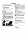
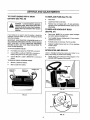
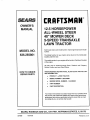
MODEL NO.
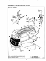
536°255861
®
12.5 HORSEPOWER
AL
L STEER
40" MOWER
5=SI
TRANSAXLE
LAWN TRACTO
Caution:
Read and follow
all Safety Rules
and Instructions
Before Operating
This Equipment
i
illlllll,llllllllll
i
i
ill
l
i i
,
=
=
,
®
Assembly
Operation
Customer Responsibilities
Service and Adjustment
Repair Parts
SEARS, ROEBUCK AND CO., HOFFMAN ESTATES, IL 60179
SAFETY RULES
THESE INSTRUCTIONSARE FOR YOUR PROTECTION.PLEASE READTHEM CAREFULLY.
IMPORTANT
THIS CUTTING MACHINE tS CAPABLE OF AMPUTATING HANDS AND FEET AND THROWING OBJECTS+ FAILURE 'TO OBSERVE THE
FOLLOWING SAFETY INSTRUCTIONS COULD RESULT IN SERIOUS INJURY OR DEATH.
L
GENERAL
e
•
Know controls and how to stop qutcl_tyo
Reed, understand, and foUow all Instructions
In the manual and
on the machine before starting.
Only allow
responsible
adults,
who are familiar
with
instructions, to operate the machine.
Wear safety
glasses or eye shields
when assembling
or
operating the machine.
Do not operate
machine
when barefooted+
Always
wear
substantial footwear, preferably
steel-toed shoes.
Do not wear loose fitting cfothing
that could get caught in
moving parts.
Clear the area of objects such as rocks, toys, wire, etc., which
could be picked up and thrown by the blade(s)+
Be sure the area is clear of other people before mowing. Stop
machine if anyone enters the area.
Never carry passengers_
Do not mow in reverse unless absolutely
necessary. Always
look down and behind before and while backing.
Be aware of the mower discharge direction and do not point it at
anyone+ Do not operate the mower without either the entire
grass catcher or the guard in place+
Slow down before turnlng_
Never leave a running machine unattended_ Always
turn off
blades, set parking brake, stop engine, and remove keys before
dismounting.
Turn off blade(s) when not mowing+
Stop engine before removing
grass catcher or unclogging
chute°
Mow only in daylight or good artificial |fghL
Do not operate the machine while under the influence of alcohol
or drugs.
Watch for traffic when Operating near or crossing roadways
Use care when mowing
around a fixed object to prevent the
blade(s) from striking It. Never deliberately
run over any foreign
objecL
Usa extra care when loading or unloading the machine into a
belier or truck.
Use care when putllng loads or using heavy equipmenL
e.
Use only approved drewbar hitch points.
b_ Limit loads to those that you can safely control.
c+ Do not turn sharply. Use care when backing.
do Use counterweight(s),
wheel weight or tire chains when
suggested in attachment(s)
instructions.
•
•
e
•
•
•
•
•
•
•
•
•
•
•
•
•
•
•
•
IL
SLOPE
Tregtc accidents
can occur if the operator is not alert to the presence
of children. Children are often attracted
to the machine and the
mowing activlty_ Never assume that children will remain where you
lest saw them.
•
Keep children out of the mowing area and under the watchful
care of another responsible adult.
e
Be alert and turn machine off if children enter the area.
•
Before end when becking, look behind and down for small
children+
•
Never carry children. They may fail off and be seriously +nJured
or Interfere with safe machine operation.
•
Never allow children to operate the machine.
•
Use extra care when approaching
blind corners, shrubs, trees,
or other objects that may obscure vision.
IV,
SERVICE:
•
Use extra care in handling gasoline and other fuels. They are
flammable and vapors are explosive.
a.
Use only an approvedcontatner_.
b.
Never remove gas cap or add fuel with the engine running+
AIIow engine to cool before re-fueling. Do not smoke.
c,
Never re-fuetthe machtneindoors.
d.
Never store the machine or fuel container
inside where
there is an open flame, such as in e water heater.
Check
fuel suppty
before
each use allowing
space for
expansion
as the heat of the engine and/or sun can cause
gasoline to expend end overflow the tank,
Use extra care when handling battery acid+ Acid contact with
skin may cause severe
burns.
Eye contact
may cause
blindness.
Use extra care when servicing
the battery. Explosive gas ts
produced
[n the battery.
Do not service
the battery while
smoking or near an open spark or f!ame+ This may cause the
battery to explode causing serious injury.
Never run a machine
Inside a closed area. Exhaust
fumes
contain CARBON
MONOXIDE,
an ODORLESS
and DEADLY
GAS.
Keep nuts and bolts, especially blade attachment
bolts, tight
and keep equipment in good condition°
Never' tamper
with safety devices+ Check their operation
regulariy_
Do not change the engine governor
settings or over speed
engine.
Reduce fire hazards. Keep machine free of grass, leaves, or
other debris build-up.
Clean up oil or fuel spillage+ Allow
machine to coot before storing,
Stop end inspect the equipment If you strike an object. Repair, if
necessary, before restarting.
Never make adjustments
or repairs with the engine running+
Grass catcher components
are subject to wear, damager and
deterioration,
which could expose
moving parts or allow
objects to be thrown+ Frequently
check components
end
replace
with manufacturer's
recommended
parts, when
necessary.
Mower blade(s) are sharp end can cuL Wrap the blade(s) or
wear gloves, and use extra caution when servicing them.
Check brake operation
frequently,
Adjust and service
as
required.
•
•
e
e
OPERATION:
•
•
•
•
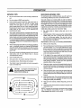
Mow up and down slopes, not across°
Remove obstacles such as rocks, tree limbs, etc.
Watch for holes, ruts, or bumps. Uneven terrain couid overturn
the rrachlne. Tall grass can hide obstacles.
•
Use slow speed, Choose a low gear so that you w_lI not have to
stop or shift while on the stops+
•
Follow the manufacturer's
recommendations
for wheel weights
or counterweights
to improve stability+
•
Use extra care w_th grass catchers or other attachments. These
can change the stability of the machine.
•
Keep el! movement
on the slopes slow end gradual
Do not
make sudden changes in speed or direction.
•
Avoid starting or stopping on a slope. If tires toss traction, turn
off the blade(s) and proceed slowly straight down the slope+
DO NOT
l_k
CHILDREN:
•
•
•
•
•
lU.
e
Slopes are o major factor related to loss*of*control
and tip-over
accidents,
which can result in severe injury or death, Aft slopes
require extra caution. If you cannot back up the slope or if you feel
uneasy on it, do not mow tL
DO
•
•
mower could suddenly turn over if a wheel is over the edge of a
cliff or ditch, or If an edge caves In+
Do not mow on wet grass. Reduced
traction
could cause
sliding.
Do nor try to stabilize the machine by puffing your foot on the
ground.
Do not use grass catcher on steep slopes.
OPERATION:
•
•
•
•
•
Do not turn on slopes unless necessary, end then slowly and
gradually downhill, If possible+
Do not mow near dtopoffs,
ditches or embankments.
The
LOOK FOR
BECOME
ALERT!!!
THIS SYMBOL
YOUR SAFETY
TO POINT
IS INVOLVED.
OUT IMPORTANT SAFETY PRECAUTIONS. IT MEANS-ATTENTIONtI[
2
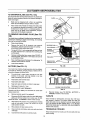
CONGRATULATIONS on your purchase of a Sears
Craftsman Tractor. It has been designed, engineered
and manufactured to give you the best possible dependability and performance
Should you experience any problem you cannot easily
remedy, please contact your nearest Sears Service
CenterlDepartment, We have competent, well-trained
technicians and the proper
unit..
Please read and retain this
enable you to assemble
properly_ Always observe
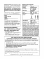
HORSE POWER:
12.5
i GALLONS
UNLEADEDREGULAR
OIL (1 Quart)
SAE 30 - above32°F.
5W - 30"- below32°F.
too!s to service or repair this
SPARKPLUG :
manual. The instructions will
and maintain your tractor
the "SAFETY RULES.."
VALVE
CLEARANCE:
GROUND
SPEED:
ChampionN*4C
(GAP .030 in.)
Intake: ,004 -,,006 In,
Exhaust:.007- .009 ln.
FORWARD
MPH
1st
1,52
2nd
2 30
MPH
3rd
292
MPH
MPH
4th
3.44
5th
5,.16
MPH
MPH
REVERSE:
2.45
SERIAL
NUMBER
DATE OF
PURCHASE
TIRE PRESSURE:
THE MODEL AND SERIAL NUMBERS WILL BE
FOUND ON A PLATE UNDER THE SEAT
CHARGING SYSTEM:
YOU SHOULD RECORD BOTH SERIAL NUMBER
AND DATE OF PURCHASE AND KEEP IN A SAFE
PLACE FOR FUTURE REFERENCE_
MAINTENANCE
BLADEBOLT TORQUE:
AGREEMENT
A Sears Maintenance Agreement is available on this
product. Contact your nearest Sears Store for details,,
CUSTOMER RESPONSIBILITIES
Read andobservesafety rules,
Followa regularschedulein maintaining,caringfor and
using yourunit,,
Followthe instructionsunder "Customer Responsibilities" and "Storage" sections of this manual
o
CRAFTSMAN
LIMITED
SPECIFICATIONS
GASOLINE
CAPACITY:
MODEL
NUMBER 536.255861
=
e
PRODUCT
TWO
YEAR
ELECTRIC
WARRANTY
FRONT: 14 PSI
REAR:
10 PSI
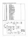
3 AMPS DC: 5AMP AC
@ 36O0RPM
30-35 FT., LBS.
WARNING: This unit is equipped with an internal combustion engine and should not be used on or near any
unimproved forest-covered, brush-covered or grass_
covered land unless the engine's exhaust syste_m is
equipped With a spark arrester meeting applicable local
or state laws (if any). If a spark arrester is used, it should
be maintained in effective working order by the operator.
In the state of Califomia the above is required by law
(Section 4442 of the Califomia Public Resources Code).
Other states may have similar laws. Federal laws apply
on federal lands_ A spark arrester for the muffler is
avaitablethrough your nearest Sears Authorized Service
Center (See REPAIR PARTS section in this manual),
START RIDING EQUIPMENT
ON ELECTRIC
START
RIDING
EQUIPMENT
For two (2) yearsfrom the dateof purchase,ifthisridingequipment ismaintained,lubricated andtuned-upaccordingto the
instructions
in the owner's manual, Searswillrepairor replace, any partsfoundto be defective in material or workmanship..
This warranty does not cover:
•
•
Expendable items which become worn during normal use, such as blades, spark plugs, air cleaners and bettso
Tire replacement or repair caused by punctures from outside objects, Such as nails, thorns, stumps, or glass_
e
Repairs necessary be_,ause of operator abuse, negligence, improper storage or accident or the failure to maintain the
equipment according to the instructions contained in the operator's manual_
Riding equipment used for commercial or rental purposes.
•
LIMITED 90 DAY WARRANTY ON BATTERY
For 90 days from the date of purchase, if any battery included with this ridingequipment proves defective in material or
workmanship and our testing determines the battery will not hold a charge, Sears wiltreplace the battery at no charge,,
WARRANTY SERVICE IS AVAILABLE BY RETURNING THE RIDING EQUIPMENT TO THE NEAREST SEARS SERVICE
CENTER/DEPARTMENT IN THE UNITED STATES.
This warranty gives you specific legal rights,and you may also have other rights which may vary from state to
state.
SEARS, ROEBUCK AND COo, D/817WA, HOFFMAN ESTATES, IL 60179
TABLE OF CONTENTS
ASSEMBLY ..............................................
OPERATION ..........................................
SERVICE AND ADJUSTMENTS ...........
TROUBLE SHOOTING ..........................
STORAGE ...................................................
REPAIR PARTS ................ ;....................
PARTS ORDERING/SERVICE
..... Back
SAFETY RULES ...........................................
2
PRODUCT
SPECIFICATIONS
......................
3
CUSTOMER
RESPONSIBILITIES
.... 3, 16-22
WARRANTY
...................................................
3
TABLE OF CONTENTS
................................
4
INDEX ...................................
.........................
4
TRACTOR
ACCESSORIES
..........................
5
CONTENTS
OF HARDWARE
PACK ............ 6
7-10
11-15
23-32
33-34
35
36-69
Cover
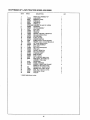
INDEX
E
A
Options:
Accessories .....................................................
5
Electrical:
Accessories ................................................
5
Interlocks and Relays ..................... 31
Spark Arrester ........................................
3, 21
Adjustments:
P
Blade Brake ..............................................
26
Brake .....................................................................
29
Parking Brake ...............................
12-13
Engine:
Air Cleaner ............................................
21
Carburetor ..................................................
33
Parts Bag ..................................
6
Air Intake Screen ..................................
20
Mower Deck Leveling:
Product Specifications ..................................
3
R
Front-To-Rear ...............................................
25
Cooling Stysem ...................................
21
Side-To-Side ...............................................
24
Oil Change ................................................
20
Repair Parts ................................
36-69
Tractor .........................................36-63
OilLevel ..............................................
14, 20
Mower Deck Height .............................
25
Seat .................................................................
28
Oil Type ............................................
3, 20
Engine .....................................................
64-67
Throttle Control Cable .....................
:.32
Transmission .............................
68-69
Preparation ..........................................
14
S
Air Cleaner, Engine .................................
21
Starting ..........................................................
14
Storage ...............................................
35
Safety Rule .........................................................
2
Air Intake Screen, Engine ....................
20
F
Service and Adjustments ................
23-32
Assembly ....................................................
7-10
B
Filter:
Blade Brake...................................................
26
AirCleaner...................................................
21
Carburetor ..................................................
32
Battery:
Fuel ....................................................................
22
Control Lever .............................
30
Charging ..................................................
9
Fuel:
Fuse ..............................................................................
31
Cleaning ..........................................................
19
Hood Rem0val/InstaUation ...............32
Installation ...............................................
10
Type .......................................................
3, 14
Traction Ddve Belt:
Levels ...................................................
9, 19
Storage ..............................................................
35
H
Removal/Replacement .............................
28
Preparation ....................................................
8
Mower Blade Drive Belt:
Starting with Weak Battery ...............
31
Headlights
.....................................................
31
Hood Removal/Instatfaltion .......................
32
Removal/Replacement ..................
27
Storage .....................................................
35
L
Terminals ..................................................
19
Blade Brake Adjustment ....................
26
Belt:
Leveling, Mower Deck .....................
24-25
Mower Deck Adjustment:
Front-To-Rear ........................................
25
Traction Drive
Lubrication:
Chart..............................................................
17
Side-To-Side ........................................
24
Removal!Replacement .................. 28
Mower Blade Drive
M
Mower Deck Height .........................25
Mower Deck Removal ....................
23-24
Mower:
Removal/Replacement ....................27
Mower Deck installation ........... 23-24
Blade:
Adjustment, Front-To-Rear ...................
25
Seat ................................................ 28
Blade Care .........................................
18
Adjustment, Side-To-Side ......................
24
Adjustment, Deck Height .....................
25
Steering Gear ................................ 29
Sharpening ...........................................
19
T_reCare .....................................
9, 18, 30
Blade Sharpening ...................................
19
Replacement .....................................t8
Throttle
Control
............................
32
Blade Replacement ...............................
18
Brake Adjustment..........................................
29
C
Wheel Repair ......................................
30
Brake Adjustment ..............................
29
CuttingHeight...................................
13
Spark Plugs ...................................... 21
Carburetor Adjustment ..........................
32
Installation ............................................
23-24
Controls, Tractor,,.................................11
Specifications ..............................................
3
Operation ..................................................
13
Starting the Engine ............................. 14
Customer Responsibilities .......3, 16-22
Removal ...........................................
23-24
Steering Wheel
7
Air Cleaner, Engine ................................
21
Air Intake Screen, Engine ...............20
Mowing/Mulching Tips ................................
15
Stopping the Tractor ........................................
12
Muffler
...............................................................
21
Storage ......................................................
35
Battery ..........................................................
19
T
Blade ....................................................
18-19
Mulching Plug Removal ......................19
Table of Contents ................................ 4
Spark Arrester .....................................
3, 21
Brake Operation .......................................
18
O
Throttle Control Cable
Cooling Systems, Engine ...............20
Oil:
Adjustment ....................................... 32
Engine Oil ......................................3, 20
Fuel Fifter ..................................................
22
Cold Weather Conditions ..........13, 20
Tires .......................................................
9, 18, 30
Lubrication Chart ...............................17
Tire Pressure ..............................
3, 9, 16
Engine .........................................................
20
Transaxle:
Schedule ..............................................
16
Storage .........................................................
35
Type .................................................
3, 17, 20
Cooling.................................
19
Spark Plugs ........................................21
Operation ........................................11-t5
Troubleshooting Points
:33-34
Tire Care ..................................
9, 18, 30
W
Operating Your Mower ...............................
13
Cutting Height, Mower ..............................
13
Warranty..................................
3
................................................
....................
4
ACCESSORIES
AND ATTACHMENTS
These accessories and attachments were available when the unit was purchased. They are also available at most Sears retail
outlets, catalog and service centers, Most Sears stores can order these items for you when you provide the model number of your
tractor
ENGINE
CUSTOMER
RESPONSIBILITIES
SPARK PLUG
MUFFLER
_lR FILTER
GAS CAN
ENGINE OIL
STABILIZER
BLADES
BELTS
PERFORMANCE
Sears offers a wide variety of attachments that fit your vehicle.. Many of these are listed below with brief explanations of holythey
can help you. This list was current at the time of publication;however, it may change in future years - more attachments may be
added, changes may be made in these attachments, or some may no longer be available or fit your model, Contact your nearest
Sears store for the accessories and attachments that are avaflable for your unit.
Most of these attachments do not require additional hitches or conversion kits (those that do are indicated) and are designed for
easy attaching
GRASS
and deattaching.
CATCHER
lets
you
collect
grass
leaves for a healthier,
nearer looking lawn,
LAWN SWEEPERS
leaves°
lets you
collect
grass
clippings
and
GAUGE WHEEL KIT helps to eliminate lawn scalping in
rough or hilly terrain,
clippings
and
SPRAYERS use 12-voft DC electric motor that connects to
the tractor battery or other 12-volt source. Includes booms for
automatic spraying when pulling, and hand wand lot spot
spraying° Wand has adjustable spray pattern, For applying
herbicides, insecticides,fungicides, and liquid fertilizers,,
LAWN VACS for powerful collections of heavy grass
clippings and leaves Wand attachment to pick up debris in
hard-to-reach places,
CARTS make hauling easY_Variety of sizes available.
ROLLER for smoother lawn surface. 36-inch wide, 18 inch
diameter water-tight drum holds up to 390 lbs,, ol weight,
Rounded edges prevent harm to turf. Adjustable scraper automatically cleans drum.,
SPREADER/SEEDERS make seeding, fertilizing, and weed
killing easy,,Broadcast spreaders are also useful for granular
de-icers and sand,
CORING AERATOR takes small plugs out of soil to afiow
moisture and nutrients to reach grass roots, 36-inch swath, 24
hardened steel coring tips, 150 lbs, capacity weight tray,,
AERATOR promotes deep root growth for a healthy lawn,.
Tapered 2.5 inch steel spikes mounted on 10-inch diameter
discs puncture holes in soil at intervals to let moisture soak in,
Steel weight tray for increased penetration.
48" SNOW BLADE has a rugged, heavy gauge steel blade,
Spring loaded blade glides over uneven surfaces, Can be adjusted from seat for straight position, or 35 degrees left or
fight, Locks in raised position for traveling Wheel and tire
chains are recommended.
SINGLE-STAGE SNOW THROWER has a 42-inch swath
capable of moving more than 70 tons of snow per hour and
throwing it accurately in any direction you choose. Driver controlled discharge chute turns a 160 degree arc. Wheel
weights and tire chains are recommended
TIRE CHAINS are heavy duty for added traction, Specify tire
size when ordering
WHEEL WEIGHTS for front and rear wheels, provide needed
traction for snow removal or dozing heavy materials In pairs
(30 lbs each,)
Jl_,
i
i iil,ii
i ill ill ii
i
iii iiiiii
illllll
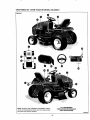
Parts packed separately in carton
,IJII
II Ill
IIIIllllll
i i illll Hlll,ll,ll,iH,H,ILI1,1,,/
,,,,lllllll Illlll
1
© ==
t1'
i
!
I
1
....
Steering Wheel
Parts Bag
'"
Seat
L
Battery Acid
i
•Owner's Manual
Parts Bag contents shown actual size unless noted
Steering Wheel Assembly Parts
1 - Spring Pin
1 - Spare Key
1 - Mower Clutch Lever Knob
4 - 5/16 x 3/4 tnch Hex Head Screws
4- 5/16 Inch Split Lockwashers
6
4 - 11/32 Inch Flatwashers
ii ii ii illllllll
ASSEMBL Y
TOOLS REQUIRED FOR ASSEMBLY
STEERING
A socket wrench wifl make assembly easier Standard wrench
sizes are listed,
(t) Pliers
(!)
NGPIN
Utility knife
(1) Screwdriver (Small Phillips with a 1/4 inch shank)
(1) Hammer
(1) Tire pressure gauge
STEERING
SHAFT
(2) 7/16 inch wrenches
(1) 3/8 inch wrench
(t)
t/2 inch wrench
(1) Tape measure
When right and left hand is mentioned in this manual, it
means when you are in the operating position (seated behind
the steering wheel),
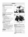
TO REMOVE
TRACTOR
FROM
CUTTING
HEIGHT
ADJUSTMENT
LEVER
CARTON
UNPACK
FIG. 1
BRAKE-CLUTCH
PEDAL
CARTON
e
Remove cardboard from top of wood crate
e
Remove top frame from carton.
e
Carefully remove contents of parts box (see CONTENTS
OF HARDWARE PACK on page 6),
•
Cut down corners of panels with a utility knife and lay
panels down,
o
Remove cardboard from chute deflector on deck_
e
Remove protective plastic wrap from hood°
TO INSTALL
STEERING
CHLTrE DEFLECTOR
WHEEL
VIEW FROM RIGHT SIDE OF TRACTOR
(See FIG. 1)
e
Position front wheels straight forward,
e
Place steering
wheel
on
steering wheel down firmiy,
e
Align cross holes in steering wheel with holes in
steering shaft° NOTE; Use a small Phillips screwdriver with a 114 inch shaft to align the holes,, Keep
screwdriver in place as you drive the spring pin inn
®
SHIFT CONTROL
LEVER
steering
FtGo2
shaft,
Push
BEFORE
From the left side, drive spring pin (found in parts bag)
throughopposite side with a hammer,
TO INSTALL ATTACHMENT
LEVER KNOB
CLUTCH
(See FIG. 1)
•
lnstall knob (found in parts bag) onto atta_;hment clutch
lever.
ROLLING
TRACTOR
OFF SKID
(See FIG. 2)
IMPORTANT: CHECK FOR AND REMOVE STAPLES tN
SKID THAT MAY PUNCTURE TIRES OF TRACTOR BEFORE
ATTEMPTING TO ROLL OFF SKID
e
Carefully cut wire ties (front and back) holding tractor to
skid,
e
Release
pedal,
e
Place shift control lever in NEUTRAL position.
e
Place cutting height adjustment lever into highest cut
position,
e
Carefully
roll tractor
backwards
off
(ASSISTANCE MAY BE REQUIRED )
IMPORTANT:
FENDER,
parking
brake by depressing
DO NOT LIFT TRACTOR
brake-clutch
wood
skid,
BY HOOD OR
ASSEMBLY
HOW TO SET UP YOUR TRACTOR
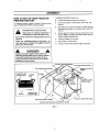
PREPARE BATTERY
TO REMOVE BATTERY (See FIG, 3) •
Cut Wire tie holding seat plate to seat spring,,
For shipping purposes, battery is installed, Remove battery
(see TO REMOVE BATTERY instructions below),
•
Disconnect negative (-) black battery cable using 7t16"
wrenchs,
•
Slide battery boot away from positive(+) battery terminal
and disconnect positive (+) red battery cable using 7/t6"
wrenchs,
e
Remove bolt from battery hold-down bracket with a 3t8"
wrench, NOTE: Lay battery hold-down bracket and bolt
aside for battery installationlater
•
Carefully lift battery out ot tractor,,
•
Place battery on level surface,
•
Proceed TO ACTIVATE THE BATTERY instructions.
CAUTION:
Wear
and face
shield.
Wash hands
or eye
clothing
Immediately
if
accidentallyIn contact with battery acid.
Do not smoke. Fumes from charged battery acid are
explosive.
Follow the CAUTIONS located on the battery. Always wear gloves, clothing and goggles to protect
your hands, skin and eyes.
DANGER
Always disconnect negative (black) cable first.
Removing positive cable first can result In sparks if
the wrench touches any metal surface. Be sure
battery hold-down bracket does not touch battery
terminals and cause a spark.
BATTERY HOLD-DOWN
BRACKET
1t4 X 314 iNCH HEX HEAD SCREW
1/4 X 3/4 INCH HEX HEAD SCREW
NEGATIVE BLACK
BATTERY CABLE
NEGATIVE 1-) BATTERY
TERMINAL
BATTERY
BATTERY
BOOT
NEGATIVE (-) BLACK
BATTERY CABLE
BATTERY
POSITIVE
(+) RED
BATTERY
CABLE
POSITIVE 1+) RED BATTERY CABLE
POSITIVE (*)
CUT-AWAY
ViEW FROM RIGHT-HAND
FIG. 3
SIDE OF TRACTOR
ASSEMBL Y
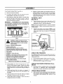
TO ACTIVATE THE BATTERY
(See FIG 4) -
e
Removevent
e
Fill battery with battery acid. Fitl each celf until it
reaches bottom of vent wells.. Do not over flit
e
Allow battery to stand and settle for at least thirty
minutes and then check level of acid.. If acid is
below level outlined on electrolyte package, add more
acid until correct level is reached.
Dispose of excess battery acid, Neutralize acid for disposal by adding it to four inches of water in a five (5} gallon plastic container, Stir with a wooden or plastic paddle
while adding baking soda until the addition of more soda
causes no more foaming.
caps from battery,
TO INSTALL SEAT
(See FIG. 5)
e
IMPORTANT:
TO MAXIMIZE LIFE OF YOUR BA'I3-ERY,
tT IS NECESSARY THE BATTERY BE CHARGED BEFORE
USE. FAILURE TO CHARGE BATTERY CAN RESULT IN
SHORTENED BATFERY LIFE
VENT
WELL
Raise seat plate and secure seat to plate with four 5/16
x 3/4 inch hex head screws, four 5/16 inch split
Iockwashers and four 11132inch t_atwashers
NOTE: Seat may be adjusted forward or rearward to desired
operator's position° Tighten mounting screws securely with a
t/2 inch wrench.
e
Connect seat switch to wire harness NOTE: If seat
sw_tch is not connected to wire harness, engine will stop
when mower clutch Iever is placed in ON (engaged)
position
BATTERY
CELL ACiD
LEVEL
FIG. 4
11t32 iNCH
FLATWASHER
\
itCAUTION:
Is an acid Handle
and poison,.
Always
wear
eye
electrolyte
with
care,
shtelds, and protect skin when handling
acid or battery,.
POISON - CAUSES SEVERE BURNS
Contains sulfuric acid,
Avoid contact with skin, eyes or clothing.
To prevent accidents, neutralize excess acid with
baking soda and rinse empty container with water°
5116 INCH SPLIT
LOCKWASHER
5/76 X 3/4 iNCH
HEX HEAD SCREW
iEAT PLATE
WiRE HARNESS
FIG,, 5
TREATMENT:
EXTERNAL - Flush with water..
CHECK
INTERNAL - Drink large quantities of water or milk.
Follow with milk of magnesia, beaten eggs or
vegetable oil, Call physician immediately°
For shipping purposes, the tires on your tractor were over-ira
flated at the factory..Correct tire pressure is importantfor best
cutting performance
EYES -_Flush with water for 15 minutes and get
prompt medical attention,.
e
Use tire pressure gauge to check amount of air in tires
e
Reduce tire pressure to PSI shown in _PRODUCT
SPECIFICATIONS" on page 3 of this manual
KEEP OUT OF THE REACH OF CHILDREN
O
o
Charge battery at a rate of six (6) amps for I hour
Use a 12-volt battery charger. Observe aft safety
.precautions required for battery charging Complete assembly section of this manual while waiting for battery to
charge°
Check acid level after the battery is charged. If
acid has fallen below correct level, add distilled or iron
free water.
e
Install vent caps to cover vent wells Wash top of battery
with water to remove any acid, then wipe dry
•
Check battery case for leakage to make sure that no
damage has occurred in handling,
TIRE
PRESSURE
CHECK FOR PROPER POSITION OF ALL
BELTS
e
See figures shown for replacing motion and mower blade
drive belts in SERVICE
AND ADJUSTMENTS
section of this manual, Verify be_ts are routed correctly
CHECK
•
BRAKE
SYSTEM
After you Iearn how to operate your tractor, check opera*
lion of tractor brake (see BRAKE OPERATION
in
CUSTOMER
RESPONSIBILITIES
section o! this
manuaE),
ASSEMBLY
DANGER
•
Position battery hold-down bracket onto top left edge of
battery (opposite terminals).
•
Reinstall bolt. Tighten bolt to secure battery,
•
Attach positive (+) red battery cable to positive (+)
terminal on battery with a 1/4 X 3/4 inch head screw and
a 1/4 inch keps nut, Tighten nut securely,
•
Place battery boot over positive(+) battery terminal (see
Fig, 6 inset).
•
Attach negative (.) black battery cable to negative (*)
terminal on battery with a 1/4 X 3/4 inch hex head screw
and a 1/4 inch keps nut. Tighten nut securely.
Always connect positive (red) cable firsL Connecting negative cable first can result In sparks if the
wrench touches any metal surface. Be sure battery
hold-down bracket does not touch battery terminals
and cause a spark_
REINSTALL
CHARGED
BATTERY
(See FIG. 6)
•
Raise seat and place battery
back in tractor
with positive(+) terminal toward rear of tractor. NOTE: Be
sure ignition key is in OFF position,
BATTERY HOLD.DOWN
BRACKET
BOLT
%
114 X 3/4 INCH HEX HEAD SCREW
114 X 3/4 INCH HEX HEAD SCREW
NEGATIVE BLACK
BATTERY CABLE
NEGATIVE(-] BATTERY
TERMINAL
BATTERY
BATTERY
BOOT
NEGATIVE (-) BLACK
BATTERY CABLE
\
PoSrrlVE (+) RED
BATTERY
BATTERY CABLE
POSITIVE (+) RED BATTERY CABLE
POSITIVE (,,) BATTERY TERMINAL
CUT-AWAY VIEW FROM RIGHT-HAND
SIDE OF _ RACTOR
FIG. 6
,/
CHECKLIST
BEFORE YOU OPERATE AND ENJOY YOUR NEW
TRACTOR, WE WISH TO ASSURE THAT YOU RECEIVE
THE BEST PERFORMANCE AND SA TISFACTfON FROM
THtS QUALITY PRODUCT,
/
Check mower and drive befts. Be sure they are routed
properly around pulleys and inside aUbelt guides.
!/'
Check wiring. See that atl connections are secure and
wires are properly clamped_
WHILE LEARNING HOW TO USE YOUR TRACTOR,
PAY EXTRA
ATTENTION
TO THE FOLLOWING
IMPORTANT ITEMS:
PLEASE REVIEW THE FOLLOWING CHECKLIST:
/
AU assembly instructionshave been compteted_
,/'
No'remaining loose parts in carton.
/,f
Engine oil is at proper level.
4"
Battery is property prepared and charged. (Minimum 1
hour at 6 amps),,
,//
Fuel tank is filled with fresh, clean, regular Unleaded
gasoline,
,t'
Seat is adjusted comfortably and tightened securely
,/#" Become famitiar with all controls-their location and
function, Operate controls before starting engine,
/
All tires are properly inflated_(For shipping purposes, the
tires were over-inflated at the factory),
//
.t"
Be sure mower deck is propedy leveied side-to-side/
front-to-rear for best cutting resuitso (Tires must be properly inflated for leveling)
10
Be sure brake system is in safe operating condition,
" OPERATION
KNOW YOUR TRACTOR
READ THIS OWNER'S
TRACTOR
MANUAL AND SAFETY RULES BEFORE OPERATING
YOUR
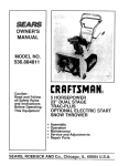
Compare illustrations (see FIG, 7) with your tractorto familiarize yourself with locations of various controlsand adjustments,
Save this manual for future reference,
ATTACHMENT
CLUTCH LEVER
MOVE THROTTLE
HERE FOR
SHIFTCONTROL
"rHROTTLE
CONTROL
LEVER
i:ii
LEVER
cU'rTING HEIGH'r
ADJUSTMENT LEVER
SW_CH
BRAKE,_LUTCH
PEDAL
SEARS LAWN TRACTORS conform to the safety standards of THE+AMERICAN NA,T_NAL STANDARDS INSTITUTE
Ignition Switch - Used to start and stop engine,,
Throttle
choke_
Control Lever.
"_ltlft ControlLever - Used to select ground speed ranges
and direction of motion (forward-neutral-reverse).
Controls speed of engine and
Parking Brake Latch. Used to lock brake.cfutchpedat down
in park position.,
Headlight Switch - Turns headlights on or off
Cutting Height Adjustment lever - Used to change heightof
cut,
Ammeter * Shows battery is being charged when engine is
running.,
Brake-Clutch
Pedal - Used to ctutch and brake
tractor and start engine.
Attachment Clutch Lever - Used to engage or disengage
power to mower deck blades+
11
........... ..........................
OPERATION
I
IIIII
I
I
III
IIIII
The operation of any tractor can result in foreign objects being thrown into the eyes, which can result in
severe eye damage.. Always wear safety glasses or eye shields white operating your tractoror performing
any adjustments or repairs.
We recommend standard safety glasses, available at SEARS Retail or Catalog Stores, or a wide vision
safety mask for over your glasses,
ENGINE -
HOW TO USE YOUR TRACTOR
TO SET PARKING
•
BRAKE
e
Move throttle control to SLOW position.
•
Turn ignition key to OFF position and remove key Always
remove key when leaving vehicle to prevent unauthorized
Depress brake-clutch pedal fully (all the way down) and
hold_
•
Reach forwardwithhand and push parkingbrake latch
forward to set parking brake.
•
To release parking brake, apply pressure to brake-clutch
pedal and spring will automatically retease parking brake
latch,,
USe,
NOTE: Under certain conditions when unit is standing
idle with engine running, hot engine gases may cause "browning" of grass To eliminate this possibility, always stop engine
when stopping tractor on grass areas.
TO USE THROTTLE
STOPPING
FAST throttle position is necessary for best bagging and
mowing performance,
MOWER BLADES •
Pull the attachment clutch lever rearward to the DISEN-
o
Operating engine at other than FAST position reduces
battery charging rate and the engine cooling air flow
Q
Choke is necessary whenever you are starting a cold
engine Do not use to start a warm engine
o
Toengage CHOKE, move throttle control lever past detent
position (arrowpointstothis positon). Move throttle control
lever out of CHOKE position as engine warms.,
GAGED position,.
CAUTION: Blades wilt not stop immediately. Keep hands and feet from under
mower deck and away from discharge
chute.
TRACTOR
Depress brake-clutch pedal fuliy (all the way down)
•
Place shift control lever in NEUTRAL position.
•
Set parking brake before leaving tractor.
CONTROL
12
OPERATION
TO MOVE BACKWARD
TO OPERATE
AND FORWARD
The direction of motion (forward - reverse) and ground
speed ranges (1-2-3-4-5) are controlled by shift control
lever,,
e
e
e
MOWER
Your tractor is equipped with an operator presence sensing
switch, Any attempt by the operator to leave the seat with engine running and attachment clutch lever engaged, wilf shut
off engine,,
Start tractor with brake-clutch pedat depressed and shift
control lever in NEUTRAL position.
e
Move shift control leverto reverse or forward speed range.
NOTE: Always come to a full stop before changing direction
of motion.,
Select desired height of cut with cutting height adiustment
lever_
e
TO STARTMOWER - Slowly move attachment clutch lever
to ENGAGED position_
Slowly release brake-clutch pedal to start movement.
e
TO STOP MOWER - Move attachment clutch lever to
DISENGAGED position_
TO SELECT MOWER CUTTING HEIGHT
(SEE FIG. 7A)
CAUTION: Do not operate the mower
without either discharge chute deflector,
or entire grass catcher, on mowers so
equipped, in place.
The cutting height is selected by placing cutting height
adjustment lever in the desired height position,.The bottom
position of lever is the lowest cutting height (1) and the top
position is the highest cutting height (5)° Other positions
change height of cut approximately 1!2 inch each.
e
..........
TO OPERATE
Grasp lever with left hand and pullupward to raise mower
deck You will hear a click sound as lever passes to next
height positiom
ON HILLS
CAUTION: On slopes, be very cautious
and avoid sharp turns to prevent tipping
or loss of control. NEVER carry passengers.
Grasp teverwith left hand and pullupward slightly Depress
button on end of lever with thumb to release height adjustment lever latch and lower mower deck to desired height.,
Release latch button and allow lever to latch in place.
tf cutting blades do not cut evenly, go to "TO ADJUST
MOWER DECK HEIGHT" and "TO LEVEL MOWER DECK"
instructions.
•
Choose slowest speed before starting up or down hills.
e
Avoid stopping, starting or changing speed on hills_
e
If slowing is necessary, move throttle conlrol lever to slower
position°
e
If stopping is necessary,push brake-clutch pedal fuity (all
way down) and engage parking brake.
e
Move shift control lever to NEUTRAL position.
e
To restart movement,release parking brake and move shift
contro! lever to 1st gear. Be sure you have allowed
enough room for unit to roll slightly as you restart
movement.
e
Make all turns slowly,
TO TRANSPORTTRACTOR
e
Place cutting height adjustment lever into highest cut
position,
e
When pushingor towingyour unit, be sure shift control lever
is in NEUTRAL position,,
e
Slowly release parking brake and brake-clutch pedal.
e
Do not push or tow tractor at more than five (5) MPH
FIG. 7A
13
OPERATION
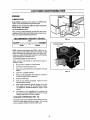
BEFORE STARTING THE ENGINE
TO START ENGINE
CHECK ENGINE OIL LEVEL
When starting engine for first time or if engine has run out of
fuel, it will take extra cranking time to move fuel from tank to
engine.
Your tractor has two lockoutswitches that connect solenoid to
brake-clutch pedal and attachment clutch lever. When starting engine, brake-clutch pedal must be fully depressed and
attachment clutch lever must be in DISENGAGED position to
engage lockout switches,,
Read OPERATION and CUSTOMER RESPONSIBILITIES
sections of this manual before tryingto start the engine.
e
Check to make sure engine crankcase is full of oil Never
run engine unless crankcase is full of oil and dipstick is
tightened securely into oil tube,,
•
To change engine ell, see ENGINE LUBRICATION in
CUSTOMER
RESPONSIBILITIES
section of this
manual°
ADD GASOLINE
•
Fill tank (see FIG 8). Use fresh, clean, regular Unleaded
gasoline. (Use of leaded gasoline willincrease carbon and
lead oxide deposits and reduce valve fife),
Your tractor is equipped with an operator presence sensing
switch. The engine will stop if operator is not firmly seated in
operator's seat when attachment clutch lever is engaged.
Leaning forward or to one side on the seat may cause the
engine to stop.
IMPORTANT': WHEN OPERATING IN TEMPERATURES BELOW 32 ° F (0 ° C), USE FRESH, CLEAN WINTER GRADE
GASOLINE TO HELP INSURE GOOD COLD WEATHER
STARTING.
WARNING: Experience indicates that a_cohol blended fuels
(called gasohol or using methanol) can attract moisture which
leadsto separation and formation of acids during storage_ Acidic
gas can damage the fuel system of an enginewhile in storage,
To avoid engine problems, the fuel system should be emptied
before storage of 30 days or ionger,_Drain fueltank, start engine
and letit run until fuel linesand carburetor are empty, Use fresh
fuel next season. See Storage Instructionsfor additional infer*
mation Never use engine or carburetor cleaner productsin the
fuettank or permanent damage may occur.
•
Depress brake-clutch pedal and set padding brake,,
e
Place the shift control lever in NEUTRAL position,
®
Move attachment clutch lever to DISENGAGED position,
o
To start a cold engine move throttle control past detent
postion for CHOKE position. For warm engine start, do not
use CHOKE position.
®
To start a warm engine move throttle control to midway
between FAST and SLOW positions
®
Turn ignitionkey clockwise to STARTposition and release
key as soon as engine starts Do not run starter
continuously for more than 15 seconds per minute_ If
engine does not start after several attempts, move throttle
to FAST position,wait a few minutes and try again,_
ALL-WHEEL
FUEL CAP
STEERING
FEATURE
Because both front and rear wheels turn, an all-wheel steering
tractor is very maneuverable, if the tractor becomes wedged
against a wa{I, fence or other obstruction,do the following:
FUEL 'TANK
®
Move shift controt lever to No, t position.
•
Turn steering wheel slightly away from obstruction,
NOTE: If you turn steering wheel sharply,rear wheels wilf
turn in opposite direction of front wheels (turning into
obstructionyou are tryingto move away from).
•
Move shift control tever to reverse position to back out of
dead ends, Be sure tractor is completely stopped before
shiftinginto reverse.
FIG. 8
CAUTION: Look down and behind before and
while backing°
CAUTION: Fill to bottom of gas tank filler
neck. Do not over fill, Wipe off any spilled
oil or fuel. Do not store, spill or use gasoline near an open flame,
14
OPERATION
MOWING TIPS
MULCHING
e
Do not use tire chains when mower housing is attached to
unit..
To mulch grass with a mulching mower, you will need to do
several thingsdifferentlythan with a conventional mower,.
e
Run the engine at FAST speed position.
o
Control forward ground speecl with shift control lever in
accordance with type and quantity of grass being
mowed.. The more grass to be cut, a slower forward
ground speed should be used. When cutting light grass,
forward ground speed can be increased. By observing
cutting action of your mower, you can determine the
forward ground speed.
You must change your mowing habits in order to maximize
effectiveness ofyour miJIching mower. This could mean slowing
down the pace that you currently use to mow your lawn to allow
the mulcher extra time to cut and recur the clippings into a fine
mulch,, The volume of grass that is under the deck of a mulcher
is greater at any time than it is with a conventionallawn mower_
e
e
e
WHEN MULCHING LAWN FOR THE FIRST TIME-
Your mower may tend to leave unmowed strips when tong
and tender grass isbeing mowed,. Tendergrass has a high
internal moisture content and is easily depressed by lawn
tractor wheels, and may not always springback in time to
be cut,To overcome this condition,we advise mowinglawn
in a counterclockwise direction,overlapping previouscut,
which allows lifting action of rotatingbladesto liftgrass into
cutting path.
e
Set cutting height at highest setting and mow in one
direction°
o
Upon completion of first mowing, lower the cutting height to
middle setting and mow a second time at 90° to first
cut or in a criss-cross pattern° You can also recut in
same direction by overlapping the center ofthe mower over
the wheel tracks of the first cut°
RETRAINING LAWN TO BE CUT WITH MULCHING MOWER-
When mowing large areas (withoutmulching pluginstalled),
start in a clockwise direction so clippings will discharged
away from shrubs, fences, driveways, etc.,After one or two
rounds, mow in coun-terclockwisedirection until finished
(see FIG 9)_
O
Mow your lawn frequently.
e
For a mulching mower to performbest, we recommend that
you remove about 1"to 1-1t2" of grasswith each cut.. Ifyour
grass is very thick or lush, you may want to remove as tittle
as 1/2" on final cut to produce the best possible result.This
could mean that you must mow your lawn every 3-5 days
under certain growing conditions.
Be sure your mower is adjusted properly,fronHo-rear and
side-to-side, (see To Level Mower Deck in Service
and Adjustments section).
e
Only cut grassthat is dry
e
Mow grass often. Short grass clippings will decay fast,
e
Keep blades sharp.. Sharp blades will cut better..
e
Your tractoris very maneuverable and can be reversedto
back out of dead ends.
MOWING TIPS
If the height of the grass should get out of control, we
recommendthatyou follow instructionsfor first time mulching to bring lawn back to a manageable height,The optimumgrassheight isdependent on grasstypeandimmediate
local growing conditions, Consult your local agricultural
extensionofficefor this information.
CAUTION:
Look down and behind before
and while backing,, Disengage mower
blades before backing up,
e
Keep your engine running at full speed (throttle at fast). If
youslow down the engine runningspeed youwillslow blade
speed as well, which will impair the ability ot the mower to
cut grass properly.
e
After mowing your lawn, check underthe mower deck to be
sure it is clean and free ot grass buildup. Do not allow the
grassto buildupbecause itwillimpair abilityof mower to cut
properly.
®
Keepthe blades sharp. They need tobe kept sharp andfree
from nicks to keep from damaging the grass tips while
cuttinggrass quicklyand efficiently.
®
Keep your lawn watered, fertilized frequently, and free of
debris.
e
Mulching mower wiltnot perform properly in wet grass_Cut
only when it is dry,
NOTE: To convert from mulching to conventionallawn mowing
see TO REMOVE MULCHING PLUG in CUSTOMER
RESPONSIBILITIES section of this manual,
.........................
FIGo9
15
CUSTOMER RESPONSIBILITIES
GENERAL RECOMMENDATIONS
BEFORE EACH USE
The warranty on this tractor does not cover items that have
been subjected to operator abuse or negligence.
To
receive full value from warranty, opera!or must maintain lawn
tractor as instructed in this manual.
•
Check engine oil level
•
Check brake operation.
o
•
Check tire pressure.
Check for loose fasteners.
Some adjustments will need to be made periodically
properly maintain your unit,,
to
All adjustments in the SERVICE AND ADJUSTMENTS
section of this manual should be checked at least once each
season.,
e
A new spark plug and clean dir cleaner assure proper
air-fuel mixture and help your engine run better and last
longer,,
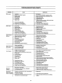
CUSTOMER
RESPONSIBILITIES
BEFORE EACH USE
AFTER FIRST 5 HOURS
FILL IN SERVICE DATES
AS YOU COMPLETE
REGULAR SERVICE
I
:_
'
_
EVERY
8 HOURS
EVERY
25 HOURS
EVERY 50 HOURS
i
ti
_
i
II
i
BEGINNING
SEASON
BEFOREEACH
STORAGE
*i
i i
.'i
i.'
......
uCheckTire Pressure
I
T ujCh,ecklor Loose Fasteners
R
Sha_en or Replace Mower Blades
A ,Lu,,bricationChart
C
Check Battery Level/Recharge
T
O Clean Batten! and Terminals
R Check Transmission Cooling
!
_
!
.....
Check Brake Operation
EVERY 100 HOURS
SERV,OE
OATES
i ! i i 1
I
•
i
I
i
i
!
..... i
!
_
!
:
:
:
!/
i/
I
"
!
:
_I
[
i /
I..... '_
i
! 4'
|....
t
i
.-,.,
..........,
i
===
i
.....
_,
"=
Adjust Blade Belt(s) Tension _
!
Adjust Motion Drive Belt(s) Tension
Check Engi,ne oil Level
change Engine Oil
....
Clean Air Cleaner (foam fi!ter)
Clean Air Intake Screen
G
Inspect Muffler/SparkArrester
I
N
E
"i i'li
/
E
N
Replace Oil Filter (il equipped)
I
.....
ij,t,
i/,.
|
,i
|j'
!
t
!
_/2
i
21
'
i
I
!
;
.....
i
:
i
I
i
/2i
i
: .............
......
I
I
i
i
i
C!eanEngine Cooling Fins
Replace Spark Plug
...............
!
1
*"
i,
!
J
;_
!
;
Roplace
Fue,
Filter
I
I
I
i
I
i
; i I
I I
_ i
i
i
/i/
; ....... i .........
Replace Air Cleaner Paper Cartridge
........................
m
.............
i
/2J
I."
I
I
i
i
i
:
E
I
(_) Change more often when opetafing under a heavy toad or in high ambient temperaLures
(2) Service more often when operaling in dirly ot dusk/conditions
(3) - Replace I_lades more often when mowing in sandy soil,
16
I
I
I
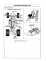
,CUSTOMER
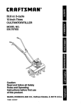
LUBRICATION
RESPONSIBILiTiES
CHART
Orientation view only_ Do Not stand on end.
PINION
Q
FRONT
AXLE
PIVOT POINTS
WHEEL
BEARINGS
END OF
DRAG LINK
) SECTOR GEAR
AND BOTTOM OF
STEERING SHAFT
,SECTOR GEAR
(_END
OF
DRAGLINK
MOWER DECK HITCH
PIVOT POINTS
Q
NWERSAL
JOINT
(SAME ON
BOTH SIDES)
STEERING
PIVOT POINTS
(SAME ON
BOTH SIDES)
Q
SAE 30 OR 10W30 MOTOR OILAPI - SG
Q
GENERAL PURPOSEGREASE
17
CUSTOMER RESPONSIBILITIES
TRACTOR
Always observe
maintenance.
safety
rules when performing
any
BENT TIP
,EDGE
BLADE
MOUNTING
SCREWS
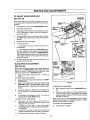
BRAKE OPERATION
Your tractor is equipped with an adjustable disc brake, To
check brake operation do the following:
•
Stop tractor on a level surface and place shift control
lever in NEUTRAL position,
e
Depress brake-clutch pedal enough to latch parking
brake in tst notch,
e
Try to push tractor. If you are unable to push tractor,
brake is too tight and should be loosened (see TO ADJUST TRACTOR BRAKE in SERVICE AND ADJUST=
MENTS section of this manual.
o
Depress brake-clutch
brake in 3rd notch_
e
Try to push tractor_If you are able to push tractor, brake
is too loose and should be tightened (see TO ADJUST
TRACTOR BRAKE in SERVICE AND ADJUSTMENTS
section of this manual
SHARP EDGE
RG.10
pedal enough to latch parking
BENT TIP EDGE
BLADE
During tractoroperation, check for stopping distance. If tractor
requires more than six (6) feet stopping distance at high
speed in highest gear, the brake must be adjusted (see to
ADJUST TRACTOR BRAKE in SERVICE AND ADJUSTMENTS section of this manua!).
SPRING
WASHERS
TIRES
•
Maintain proper air pressure
"PRODUCT SPECIFICATIONS"
manual)_
in all tires,. (See
on page 3 of this
e
Keep tires free of gasoline, oil, or insect
chemicals which can harm rubber_
control
BOLT SHOWN
GRADE 5
Avoid stumps, stones, deep ruts, sharp objects and
other hazards that may Cause tire damage.
•
•
•
•
e
BLADE
SCREW
FIG. 11
CAUTION: BEFORE PERFORMING ANY
SERVICE OR ADJUSTMENTS
•
ING
Q
Fultydepress brake-clutch pedal and set
parking brake,
Place shift control lever in NEUTRAL
position.
Place attachment clutch lever in DISENGAGED position,
Turn ignition key OFF and remove key_
Make sure the blades and all moving
parts have completely stopped,
DO NOT handle blades with bare hands.
Wear gloves or wrap blade with newspaper or other materia! while removing
or installing blade.
•
Do not attempt to sharpen blades while they are on
mower_
•
Replace bent or damaged blades.
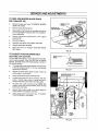
BLADE
CARE
For best results mower blades must be kept sharp. The
blades can be sharpened with a file or on a grinding
wheel We suggest they be sharpened or replaced after every
25 hours or mowing. Check blades more often if mowing in
sandy conditions.,
REMOVAL
(See FIGS. 10 and 11)
•
Remove mower deck
DECK in this section)_
(see TO REMOVE
MOWER
•
Remove blade mounting hardware securing blade..
•
Install
new blade with bent tip edges
up.
Blade will not cut if bent tip edges are not up toward top
of mower deck..
•
Secure blade to mower deck with mounting hardware
removed earlier. Be sure all parts are re-assembled in
proper order as shown.,
•
Tighten blade mounting bolts securely_ We recommend
using a 10 inch wrench or torque wrench. If a torque
wrench is used, torque bolts to between 30 -35 ft lbs).,
IMPORTANT: Blade mounting bolts ate Grade 5 heat treated
as shown in FIG. 11 inset.
18
CUSTOMER
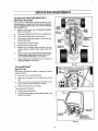
TO SHARPEN
RESPONSiBiLITIES
BLADE (See FIG. 12A)
Care should be taken to keep blade balanced An unbalanced
blade wilt cause excessive vibration and eventual damage to
mower and engine_
e
Blade can be sharpened with a file or on a grinding
wheel, Do not attempt to sharpen while on mower..
e
Place center hole of brads over head of the nail or end
of a screwdriver clamped horizontally in a vice. If blade
is balanced, _tshould remain in a horizontal position. If
either end of the blade moves downward, sharpen
heavy end until the blade is balanced.,
TO REMOVE
129)
MULCHING
cENTER HOLE
BLADE
PLUG (See FIG.
Yourtractorhas a mulching k_tinstalledon the mower deck. To
Convert from mulching to regular lawnmowing, the mulching
plug may be removed as follows:
e
Raise chute deflector°
e
Remove the two 5116-18 wingnuts, two external
tockwashers0 and two spacers from atop of mulching
plug installedinside mower deck chute°
e
The two 5/16-18 x 1 inch carriage bolts will drop and can
be easily removed from underneath the mulching ptug
and toe guard°
e
Remove mulching plug from mower chute° DO NOT remove toe guai*d, Your tractor is now ready to be used as
a conventional mower°
e
FIG. 12A
_16-18 WINGN_
EXTERNAL
LOCKWASHER
SPACER
Store mulching plug and hardware for safekeeping.. To
reinstall, reverse order of removal,
Lower Chute deflector.,
5/t6-18 X 1 INCH
CARRIAGE BOLTS
FIGo12B
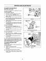
BATTERY (See FIG. 13)
Your tractor has a battery charging system which is sufficient
for normal use. However, periodic charging of battery with an
automotive charger wi!l extend its fife,
e
The acid level in each battery should be even with
bottoms of vent wells. Add only distilled or iron free
water if necessary, Do not over fill
e
Keep battery and terminals clean
•
Keep battery bolts tight,,
e
Keep vent caps and small vent holes in caps open.
e
Recharge at 6 amps for 1 hour.,
VENT CAP
VENT
BATTERY
CELL ACID
LEVEL
IIIIIII1111t_
II11t
II!1
CUT-AWAY
Ii111_1
VIEW OF BATTERY
TO CLEAN BATTERY AND TERMINALS FIG, 13
Corrosion and dirt on battery and terminals can cause slow
battery power drain.
Reinstall battery (see TO INSTALL
ASSEMBLY section of this manual),,
® - Remove terminat guard (if so equipped),
Disconnect BLACK battery cable first then RED battery
cable and remove battery from tractor (see TO REMOVE BATTERY in ASSEMBLY section of this' manuat).,
Wash battery with solution of four tablespoons of baking
soda to one gallon of water. Be careful not to get
soda solution into ceils,
e
Rinse battery with plain water and dry,,
e
Clean terminals and battery cable ends with wire brush
until bright,
•
Coat terminals with grease or petroleum jelly,
in
V-BELTS
•
®
BATTERY
Check V-belts for deterioration and wear after 100 hours
and replace if required,, The mower blade drive belt and
tractor drive belts can be adjusted to provide longer belt life
(see TO ADJUST BLADE DRIVE BELT or TO ADJUST
TRACTOR DRIVE BELT in SERVICE AND ADJUSTMENTS
section of this manual).
TRANSAXLE
COOLING
Keep transaxle free from build-up of dirt and chaff which can
restrict cooling,
19
CUSTOMER
RESPONSIBILITIES
ENGINE
OIL RLL CAP/
D1PSTICK
LUBRICATION
Read ENGINE instructions in this section and OPERATION
section of this manual before trying to _tart engine,
NOTE: Be sure oil has been added to engine crankcase
before trying to start engine,
OIL RECOMMENDATIONS
Only use high quality detergent oil rated with AP! service
classificationSO. Select the oil's SAE viscosity grade according to your expected operating temperature:
RECOMMENDEDVISCOSITY
i._
,
coLoE.,,_€_=
GRADES
32OF
5W30
FIG. 14
,,w.=.Mj.
AIR INTAKE SCREEN
SAE30
NOTE: Although multi-viscosity oils (5W30, 10W30, etco) improve starting in cold weather, these muiti_viscosity oils will
result in increased oil consumption when used above 32°Fo
Check your engine oil level more frequently to avoid possible
engine damage from running low on oil.
TO CHANGE ENGINE OIL, (See FIG. 14)
Raise and lower hood slowly to avoid personal
damage to tractor,.
injury or
•
Be sure tractor is parked on a level surface.
•
Oil wit! drain more freely when warm
•
Clean area around oil filldrain and cap before removing
dipstick.
•
Catch oil in a suitable container.
•
Remove oil fill cap/dipstick. Be careful not to aIlow dirt
to enter the engine when changing oil
•
Remove oil drain plug.
•
After oil has drained completely, replace oil drain
plug and tighten securely,
•
Refill engine crankcase with oil through oil fill tube.
Pour slowly,, Do not over fill. For approximate capacity
see PRODUCT SPECIFICATIONS on page 3 of this
manual.
•
Use gauge on oil fill capldipstick for checking level,
Be sure oil fill cap is tightened securely for accurate
reading., Keep oil at FULL line on dipstick_
FIG. 15
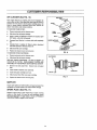
COOLING SYSTEM (See FIG. 15)
Frequently remove grass clippings, dirt and debris from cooling fins, air intake screen, levers and linkage_ This will help
ensure adequate cooling and correct engine speed.
2O
CUSTOMER
RESPONSIBILITIES
AIR CLEANER (See FIG. 16)
WING NUTS
Your engine will not run properly and may be damaged by
using a dirty air filter,, Clean loam filter after every 25 hours of
operation or every season. Service paper cartr!dge every 100
hours or every season, whichever+occurs first. Service air
cleaner more often under dusty conditions.
COVER
TO SERVICE FOAM FILTER +
e
Remove wing nuts and air cleaner cover.
e
Slide foam filter off paper cartridge,,
e
Wash in water and detergent solution and squeeze (DO
NOT twist) until all dirt +isremoved.,
e
Squeeze foam filter dry in a clean cloth until completely
dry+.
e
Saturate foam in engine oil,, Wrap in clean, absorbent
cloth and squeeze to remove excess oito
e
Slide foam filter over cartridge.
e
Replace air cleaner cover and wing nuts.
FOAM
FILTER
NUTS
PAPER CARTRIDGE
BODY
FIG. 16
TO SERVICE PAPER CARTRIDGE.
e
Remove wing nuts and air cleaner cover.
e
Slide foam filter off paper cartridge+
ELECTRODES
REPLACE PAPER CARTRIDGE. DO NOT ATTEMPT TO
CLEAN OR OIL FILTER.. REPLACEMENT FILTERS ARE
AVAILABLE AT THE NEAREST SEARS SERVICE CENTER,
e
Remove nuts and paper filler,
filter+
Discard nuts and paper
e
Clean inside air cleaner cover and body+,
e
Install new paper cartridge and nuts,,
e
Slide cleaned foam filler over paper cartridge+
•
Replace air cleaner cover and wing nuts,
PORCELAIN
+030 GAP
FIG. 17
MUFFLER
Inspect and replace corroded muffler and spark arrester (if so
equipped) as it could create a fire hazard andlor damage.
SPARK
PLUG
( See FIG. 17)
Replace spark plug at the beginning of each mowing
season or alter every 100 hours of use, whichever comes
first. Spark plug type and gap setting is shown in PRODUCT
SPECIFICATIONS on page 3 of this manual,
21
CUSTOMER RESPONSIBILITIES
IN-LINE
FUEL
FILTER
(See FIG, 17A)
Fuel filter should be replaced once each season,, tf fuel filter
becomes clogged, obstructing fuel flow to carburetor, replacement is required.. Make sure new filter is installedwith the IN
marking toward the tank and the OUT rnarking toward the engine. Check fuel system components frequently and replace
any parts showing wear or cracks.
•
With engine cool, remove filter and plug fuel line sections_
•
Place new fuel filter in position infuel line with arrow pointing
towards carburetor.
•
Be sure there are no fue!line leaks and clamps are properly
positioned.
i
Immediately wipe up any spilled gasoline.
FUEL FILTER
CLAMP
CLAMP
CLEANING
•
Clean engine, battery, seat, transaxte, finish, etc. of all
foreign matter.
•
Keep finished surfaces and wheels free of altgasoline, oil,
etc.
•
Protect painted surfaces with automotive type wax.
Flg. 17A
We do not recommend using a garden hose to clean your
tractor unless electrical system, muffler, air filter and
carburetor are covered to keep water out. Water in engine can
shorten engine life.
22
SERVICE AND ADJUSTMENTS
CAUTION: BEFORE PERFORMING ANY SERVICE OR ADJUSTMENTS
e
Depress brake-clutch pedal and Set parking brake.
e
Place shift control lever in NEUTRAL position.
•
Place attachment clutch lever In DISENGAGED position.
e
Turn ign!tlon key OFF and remove key.
®
Make sure the blades and all movtng parts have completely stopped.
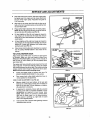
TRACTOR
!
TO REMOVE MOWER DECK
MOUNTING
BRACKET
Remove mower dec=kfrom right side of tractor+,
e
Place cutting height adjustment lever in lowest cutting
position,,
e
Remove hairpin cotter from mower deck hitch and
remove deck hitch rod from front hole of the front mounting bracket (see RG. 18),,
O
Lower deck hitch.
O
Turn front wheels all the way to the left to allow mower
deck hitch to slide past right front wheel,.
e
e
COTTER
Remove hairpin cotter and flatwasher from hanger pin of
right rear lift arm and slide off right mower deck lift
bracket (see FIG. 19),
VIEW FROM FRONT OF TRACTOR
FIG. 18
Remove hairpin cotter and flatwasher from hanger pin of
left rear lift arm and slide off left mower deck lift
bracket
(see FIG, 19)+
•
Flex lower engine pulley belt guide away from puitey (see
FIG. 20),,
e
Move mower deck forward and remove mower deck drive
belt from lower engine pulley+ Reposition belt guide_
e
Remove hairpin cotter and ftatwasher from hanger pin on
mower clutch lever betcrank strap assembty.,
e
Disconnect
mower deck engagement
belcrank strap assembly (see FIG. 21),
e
Place cutting height adjustment lever in highest cutting
position,+
e
Slide mower deck out from under right side ot tractor.
spring
_ECKHRCH
ROD
MOWER DECK
LIFT BRACKET
HAF_._-,R
PIN
(RIGHT SIDE)
REAR LIFT ARM
(RIGHT SIDE)
FLATWASHER
from
VIEW FROM RIGHT SIDE OF TRACTOR
FIG. 19
TO INSTALL MOWER DECK
e
Place cutting height adjustment lever in highestcutting
position, If cutting height is not in highest position, the
deck brackets will hit the lift arms white slidingthe deck
under the tractor.
e
Place mower deck on right side
chute deflector away from tractor..
e
Turn front wheels of tractor to maximum left turn,
•
Liftdeck hitchand slidedeck undertractor to a centered
position+
e
From left side of tractor, slide deck rearward_ Then connect mower deck engagement spring to hanger pin on
the mower clutch lever beicrank strap assembly, and
reinstall flatwasher and hairpin cotter on hanger pin
(see FIG. 21)+
LOWER ENGINE
PULLEY BELT GUIDE
of tractor with
FIG. 20
23
SERVICE AND ADJUSTMENTS
•
Slide deck toward front of tractor_ Pull lower engine pulley
belt guide away from engine and slip mower deck drive
belt onto _ower engine pulley. Reposition belt guide to
1!16" from pulley..
•
Align holes in the mower deck hitch with the front set of
holes in the front mounting bracket and reinstall the hitch
rod and hairpin cotter,
•
Place cutting height adjustment lever in lowest position.
NOTE: Be sure left and right lift arms are to the inside of
left and right deck lift brackets (see FIG. 19),
•
Lift deck slightly and flex left rear hanger pin inward to
snap hanger pin into left deck lift bracket hole, Secure
hanger pin in place with flatwasher and hairpin cotter re*
moved earlier,
•
....
,H,,llll,llll,
IDLER PULLEY
MOWER
DECK
DRIVE
BELT
MOWER DECK
SPRING
Check mower deck leveling and adjustment as required
See TO LEVEL MOWER DECK in this section of the
manual.
HANGER PIN
TO LEVEL MOWER DECK
& FLATWASHER
Adjust mower deck while tractor is parked on level ground
or driveway Make sure tires are properly inflated (see
PRODUCT SPECIFICATIONS on page 3 of this manual) if
tires are over or under inflated, you wiif not properly adjust
your mower deck.
DECK
ENGAGEMENT
SPRING
The tractor main frame should be level across front from left
side to right side_If main frame will not sit level, two outside
axle mountingscrews may be too tight. The outside mounting
screws must be loose enough to allow front axle to pivot.
NOTE: Do Not loosen center mounting screw.
•
Check and adjust height of mower deck (see TO
ADJUST MOWER DECK HEIGHT in this section)
•
Place mower deck cutting height adjustment lever in
mid-cut position for all adjustments,
FIG. 21
SIDE-TO-SIDE ADJUSTMENT ( See FIG. 22)
•
Measure height, from level surface, of left and right
blade tips at outside edge of mower deck. If blades are
equal or not more than 1t8 inch difference, no side-toside adjustment is necessary,
•
If adjustment is necessary, loosen right side eccentric
mounting screw and turn eccentric clockwise or counterclockwise as required to level mower deck_
NOTE: When groove on eccentric is pointing down,
ri_lht side of mower deck is at its lowest position
When groove is pointing up, right side of mower
deck is at its highest position,
•
Hold eccentric with a wrench while tightening eccentric
mountingscrews securely.
MOWER DECK
BELt" GUARD
DECK
HITCH
Lift deck slightly and flex right rear hanger pin inward to
snap hanger pin into right deck lift bracket slot. Secure
hanger pin in ptac e with flatwasher and hairpin cotter
removed earlier (see FIG. 19),,
•
i, i, Jl,
FIG. 22
24
SERVICE AND ADJUSTMENTS
FRONT-TO-REAR ADJUSTMENT ( See FIG. 23)
e
e
Measure height, from level surface, of right side blade
tips at front and rear of mower deck, if distances are
equal or not more than 1/8 inch lower in front, no
adjustment is necessary°
GROOVE_O_
"
-ECCENTRIC
.,_TT__
MOUNTING
•
/
J! a_=l
SCREW
FRONT ADJUSTMENT /_
_[..,,_.,,,,.,,,,,_
if adjustment is necessary, loosen front eccentric
mounting screws and turn front adjustment eccentric
clockwise or counterclockwise
as required_ NOTE:
When groove on eccentric
is pointed straight
forward,i front of mower deck is at lowest point.
Turn both eccentrics so grooves
are pointing
same direction (up or down).
ECCENTRIC /
MOWER
DECK
BRACKET
L,.-,_
|
|
_,
\ DECK
.OW
R LEVELi.G
ADJUSTMENT HOLES
FIG, 23
If more adjustment is necessary, frontof mower deck may be
raised or lowered by relocating eccentric mountingscrews in
higher or lower position on mower deck mounting bracket.
•
...... ,_"
-
Hold eccentric with a wrench while tightening eccentric
mounting screws securely,
•
Measure height of mower deck from bottom of the left
hand blade mounting screw to ground..Height should be
4 inches with mower deck set in high cut..
®
tf adjustment is necessary, block up mower deck with a
2 x 4 and set cutting height adjustment lever to tbw cut
position.,
e
Loosen hairpin cotter (see inset) from clevis pin. Remove
clevis pin_
Loosen t!4-20 hex nut on cable above clevis° Turn clevis
clockwise to raise mower deck. Turn counterclockwise to,
lower d_ck. Each 1-I/2 complete turn of clevis represents
approximately 1/8 inch change in the height of mower
deck°
TO ADJUST MOWER DECK HEIGHT
(See FIG. 24)
Before making any mower deck height adjustments check air
pressure in all four tires, All tires must be properly inflated for
mower deck height to be properly adjusted., For recommended air pressure, see "Product Specifications" on page 3,,
The main frame on the lawn tractor should be level across the
front from left side to right side. If main frame will not sit level,
the two outside axle mounting screws may be too tight. The
two outside mounting screws must be loose enough to airow
front axle to pivot, NOTE: Do Not loosen center mounting
screw_
e
o
Tighten 1/4-20 hex nut on cabte above c_eviso
o
Reinstall clevis and clevis pin, Return cutting height adjustment lever to high cut position and remove wood
block from under deck°
e
Park tractor on firm level surface, such as a driveway or
garage f!oor_
Recheck height of mower deck. Height should be 4
inches with mower deck set in high cut,, Readjust if nec-
e
Place mower deck cutting height adjustment lever in
high cut position.
es.sary,
114-20 HEX NUT k
SQUARE JAM NUT
CLEVIS PIN
MOWER DECK MOUNTING
S RACKET
HAIRPIN COTTER
VIEW FROM LEFT REAR OF TRACTOR
FIG. 24
25
SERVICE AND ADJUSTMENTS
TO ADJUST
BLADE DRIVE BELT
MOWER DECK
BELT GUARD
(See FIG. 25)
When mower btade drive belt slips and blades will not turn
at full speed when mowing, the blade drive belt should be
tightened_
•
Place attachment clutch lever in DISENGAGED position.
o
Loosen idler pulley hex nut.
o
Note position of belt retainer on idler puUey so it can be
can be repositioned properly after belt installation.
Loosen idler pulley°
•
Slide idler pulley toward rear of mower deck to tighten
bell NOTE: Only a small amount of movement should be
required.
•
Re-tighten hex nut on idler pulley
•
To check adjustment:
a.. Start engine and place throttle
position FAST_
MOWER
SPRING
BELT RETAINER
IDLER ARM
EXTENSION
IDLER PULLEY
HEX NUT
LOCKNUT
control lever in
b. Place attachment clutch lever in ENGAGED position
and allow sufficient time for blades to run to full speed,
then place attachment clutch lever in DISENGAGED position. Blades should stop within a few seconds and remain stopped. It blades do not stop or tend to creep, adjustment is too tight°
•
To loosen blade drive belt, loosen idler pulley and move
toward front of mower deck_
BLADE
BRAKE
MOWER
CLLI'TcH
SPRING
ADJUSTMENT
(See FIG. 25)
IDLER ARM
EXTENSION
Blade brakes should stop mower blades when attachment
clutch lever is in DISENGAGED position. Blade brake pads
should not come in contact with quill assemblies when
attachment clutch lever is in ENGAGED position.
IDLER PULLEY
HEX NUT
•
Place cutting height adjustment lever in lowest cut
position.
TO CHECK RIGHT HAND BRAKE •
Move attachment clutch lever backward to DISENGAGED position..
•
INSET R
FIG, 25
Begin to move attachment clutch lever forward toward
ENGAGED position and check distance lever moves
before brake pad, on right hand quill assembly, begins
to move.
TO CHECK LEFT HAND BRAKE -
Attachment clutch lever should move at least 3/4 inch,
but not more than 1 inch, before brake pad begins to
move.
•
Place attachment clutch lever in DISENGAGED position.
•
Locknut, on end of brake rod, should be approximately
1/8 inch from brake pad mountingbracket with left hand
brake pad against pulley of left hand quill assembly
(See FIG.. 25, inset A).
if the distance is not between 3/4 and 1 inch, (see TO
ADJUST RIGHT HAND BRAKE below).
NOTE: Brake pad must clear left hand quill assembly when
attachement clutch lever is in 'ENGAGED position° Tighten
locknuton end of brake rod if needed,
TO ADJUST RIGHT HAND BRAKE •
•
•
•
Note which one of five holes on front of idler arm
extension is used for attaching
mower clutch
spring (see FIG_ 25, {nset B).
If distance
is more than 1 inch, move mower
clutch cable spring to a hole toward bolts holding idler
arm extension.
If distance is less than 314 inch, move mower clutch
springto a hole toward free end of idler arm extension_
Re-check right hand brake and adjust if required.
TO ADJUST LEFT HAND BRAKE •
26
Adjust locknutif necessary°
SER V!CE A ND_A DJUSTMENTS
TO REPLACE
MOWER
BLADE
DRIVE
BELT (See FIG. 26)
MOWER DECK
BELT GUARD
e
Remove mower deck (se_ TO REMOVE
DECK Jnthis section.,
e
Remove mower deck belt guard,,
e
Note position of belt retainer on idler pulley so it can be
can be repositioned properly after belt installation,
Loosen idler pulley..
e
Remove old belt and replace with a new original
equipment belt.,
e
Reinstall belt guard
e
Reposition belt retainer and re-tighten idler pufieyo
e
Reinstall mower deck assembly..
e
Adjust belt (see TO ADJUST
BELT below).
MOWER CLUTCH
SPRING
MOWER
IDLER PULLEY
IDLER PULLEY
TRACTOR
DRIVE
FIG, 26
TO ADJUST TRACTOR DRIVE BELT
(See FIGS. 27A and 27B)
BRAKE.CLUTCH
PEDAL
The drive belt is kept tight by a spring attached to the brakeclutch pedal assembly. When the drive belt is properly
adjusted, the brake-clutch pedal should appear as shown in
fully released position
e
I
The brake-clutch pedal should appear as shown when
in the fully released position If not, then the following
adjustment .is necessary.
e
Depress the brake*c]utch pedal enough to latch the
parking brake in the 3rd notch,.
e
Loosen clutching idter pulley mounting screw.
e
if brake-clutch pedal was too far forward, slide idler
pulley in toward engine pulley. If pedal was too far
rearward, slide idler pulley away from engine pulley
e
Re-tighten idler pulley mounting screw° NOTE: Belt
retainer should point toward position where running
board meets main frame
e
Release brake_clutch pedal and re-check pedal |or
proper position and readjust if necessary,,
e
Check tractor brake adjustment (see TO ADJUST
TRACTOR BRAKE in this section)
FIG. 27A
CLUTCHING IDLER PULLEY
MOUNTING SCREW
BR,
PEDAL
%3rd
NOTCH
FIG, 27B
27
MOWER DECK
DRIVE BELT
SERVICE AND ADJUSTMENTS ..............
TO REPLACE TRACTOR
(See FIGS. 28 and 29)
DRIVE BELT
Orientation vlBwonly+ Do Not stand on end+
LOWER ENGINE PULLEY
BELT GUIDE
Your tractor uses v-belts made o! special compounds_ If any
belt becomes worn or breaks, replace with original equipment
belt (see REPAIR PARTS section of "this manual). NEVER
USE A SUBSTITUTE.
e
Remove mower deck (see TO REMOVE
DECK in this section),
LOWER
ENGINE
PULLEY
MOWER
•
Fully depress brake-clutch pedal and set parking brake,
•
Loosen clutching idler pulley mounting screw,
•
Pul! belt retainer away from pulley and remove belt from
clutching idler pulley.
•
Remove belt from transaxle pulley+,
•
Remove belt from engine put{ey+
•
Replace belt by reversing above instructions. Be sure
belt is installed to inside of upper engine pulley bett
guide,
•
Before repositioning and tightening clutchingidler pulley
and belt retainer, adjust tractor drive belt (see TO ADJUST TRACTOR DRIVE BELT in this section)_
•
Check tractor brake adjustment (see TO ADJUST
TRACTOR BRAKE in this section),
UPPER
BELT
RETAINER
PULLEY
UPPER ENGINE
PULLEY
BELTGUIDE
CLUTCHING
IDLER
PULLEY
TRANSAXLE
BELT
FIG. 28
TO ADJUST SEAT
(See FIG. 30)
The seat can be adjusted forward or rearward to desired
operator's position.
•
Raise rear of seat to horizontal position+
•
Loosen (do not remove) four hex head screws in seat
plate,
•
Pull up on seat to move it toward rear of tractor, or push
down on seat to move to toward front of tractor+
•
CLUTCHING
IDLER
Tighten hex head screws in seat plate.
PULLEY
if more adjustment is required:
•
Remove seat and seat plaie+
•
Install seat and seat plate in either forward, center or rear
holes of seat support+
,...:
FIG. 29
SEAT,
SEAT PLATE
BRACKET
FIG. 30
28
SERVICE AND ADJUSTMENTS
TO ADJUST TRACTOR
(See FIGS. 31A & 31B)
BRAKE
Your tractor is equipped with an adjustable
mounted on the transa.xleo
disc brake
TO CHECK BRAKE OPERATIONe
Stop tractor on a hard flat surface and turn off engine.
•
Place shift control lever in NEUTRAL posilion_
e
Depress brake-clutch
brake in 1st notch.
e
Try to push tractor,. If you are unable to push tractor,
brake is too tight and should be loosened (see TO
ADJUST TIGHT BRAKE below)..
BRAKE
ADJUSTING
NUT
pedal enough to latch parking
e
Depress brake-clutch
brake in 3rd notch.
e
Try to push tractor_ If you are able to push tractor, brake
is too loose and should be tightened (see TO ADJUST
Loose BRAKE below).
FIG. 31A
pedal enough to latch parking
PARKING BRAKE
LATCH
TO ADJUST LOOSE BRAKE -
NOTCHES
o
Place shift control lever in NEUTRAL position and
depress brake-clutch pedal enough to latch parking
brake in 4th notch
e
Turn brake adjusting nut clockwise until you cannot
push tractor.
e
Re-check tractor brake adjustment as outlined above_
BRAKE/CLUTCH
PEDAL
VIEW FROM RIGHT SIDE OF TRACTOR
FIG. 31 B
TO ADJUST TIGHT BRAKEPlace shift control lever in NEUTRAL position and
depress brake-clutch pedal enough to latch parking
brake in 1st nolch.
e
Turn brake adjusting nut counter-clockwise until you
can push tractor.
e
Re-check tractor brake adjustment as outlined above..
STEERING
MOUN3"|NG
SCREWS
During tractoroperation, check for stopping distance. If tractor
requires more than six (6) feet for stopping distance at high
speed in highest gear, the brake must be adjusted (see TO
ADJUST TRACTOR BRAKE as described above).
TO ADJUST STEERING
GEAR
GEAR
(See FIG. 32)
If excessive play develops
sector gears as follows:
•
•
in steering, adjust pinion and
LOWER STEERING
SHAFT BEARING
Position front wheels straight forward_
. Slightly loosen mounting
shaft bearing.
screws
FIG. 32
in lower steering
•
Move lower steering bearing forward as needed.
•
Hold bearing in place, tighten mount}ng screws
securely. Torque mounting screws to between !_ and
!8 foot pounds.
2g
SERVICE AND ADJUSTMENTS
TO ADJUST SHIFT CONTROL
LEVER
TO REMOVE WHEEL FOR REPAIRS
(See FIG. 33)
(See FIGS. 34A and 34B)
Adjustment is only required if neutral is not obtained when
shift control lever is in neutral sloL
e
Block up axle securely-.
•
On front wheels, remove dust cap, retaining ring and
washer(s) to remove wheel.
•
Place shift control lever in NEUTRAL position..
•
Release brake clutch pedal,
•
On rear wheels, remove screws to remove wheel.
•
Try to push tractor, You should be able to push
when shift control lever is in neutral position.. If you
cannot push tractor, adjust as follows,
•
Repair tire and re-assemble.
•
On rear wheels, align holes and reinstallscrews+
•
On front wheels, replace washer(s), and retaining ring.
•
Replace dust caps.
•
Disconnect ball joint from shift lever bracket by removing bail joint nut. Be careful not to move shift lever
bracket,
• ' FRONT
o
Loosen jam nut on connecting rod.
o
Place sh_ftcontrol lever in neutral slot+
O
Thread ball joint on or off connecting rod until the stud
on the ball joint goes vertically through hole in shift lever
bracket
o
install batt joint nut and tighten,
o
Tighten jam nut,
e
Check the shift control lever adjustment by pushing the
tractor, Place shift control lever in neutral slot+ You
should be able to push tractor, You should not be able to
push the tractor when shift control lever is in reverse or a
forward range position,
TIRE AND RIM ASSEMBLY
FELT WASHER
FLATWASHER
SPINDLE
FLATWAEHERS
DUST CAP
SHIFt CONTROL
LEVER
RETAINER RING
CONNECTING
RG. 34A
ROD
REAR TIRE AND RIM ASSEMBLY
NEUTRAL
SLOT
REAR
AXLE
JAM NUT
BALL JOINT
SHIFT
LEVER
BRACKET
HUB
SCREWS
FIG. 33
FIG. 34B
30
IL
+SERVICEAND ADJUSTMENTS
TO START ENGINE WITH A WEAK
TO REPLACE FUSE (See FIG. 36)
BATTERY (See FIG. 35)
e
Raise hood+
•
Locate fuse holder under dash°
e
Remove fuse and replace with a t5 amp automotive+
type plug in fuse (see REPAIR PARTS section for more
information).
+
CAUTION:
Lead-acid batteries generate
explosive gases. Keep Sparks, flame and
smoking materials away from batteries.
Always wear eye protection when around
batteries+
TO REPLACE HEADLIGHT
+
BULB
(See FIG. 37)
if your battery is too weak to start the engine, it should be
recharged. If "jumper cables" are used for emergency starting
follow this procedure+
IMPORTANT: YOUR TRACTOR IS EQUIPPED WITH A t2
VOLT NEGATIVE GROUNDED SYSTEM. OTHER VEHICLE
MUST ALSO BE A 12 VOLT NEGATIVE GROUNDED
SYSTEM. DO NOT USE YOUR TRACTOR BATTERY TO
START OTHER VEHICLES.
e
Raise hood. NOTE: Do not remove plastic headlight
lens when replacing headlight bulb,,
e
Turn headlight harness (holding butb) 1/4 turn counterclockwise and remove.
e
Pull buIb out (do not unscrew),, Push in new bulb,
e
Replace headlight harness and turn 1/4 turn clockwise
to lock in place.
e
Close hood.
TO ATTACH ;JUMPER CABLES +
INTERLOCKS
AND RELAYS
e
Push battery boot away from POSITIVE (+) terminal
e
Connect RED (+) cable to POSITIVE (+) terminal on
battery, taking care not to short against chassis+
Loose or damaged wiring may cause your tractor to run
poorly, stop running, or prevent it from starting°
e
Connect BLACK (-) cable to NEGATIVE (*) terminal on
battery.
e
Chec k wiring. See electrical wiring diagram in the
REPAIR PARTS section of this manual
TO REMOVE CABLES, REVERSE ORDER e
BLACK (°) cable from battery.
e
RED (+) cable from battery..
FUELTANK
NEGATIVE(,)
POSITIVE(,)
TERMINAL
TERMINAL \\,_
RUBBER BOOT
DASH
FIG. 36
FIG. 35
TO REMOVE,
r
S_._._I
)TO
REFNSTA\,b.
iL
HEADLIGHT
BULB
HARNESS
FIG. 37
31
SERVICE AND ADJUSTMENTS
TO REMOVE HOOD (See FIGS. 38 and 39)
ENGINE
•
Reach under front of hood and disconnect hood latch
spring,
TO ADJUST THROTTLE
•
Raise hood.
e
Disconnect headlight wire harness
•
Remove screw used to attach hood lanyard to front of
engine+ Hotd hood securely to prevent hood from falling
e
Remove hairpins and clevis pins used to attach hood to
mountingbrackets+
e
To reinstall, reverse above procedure.
CONTROL
CABLE
(See FIG. 40)
The throttle control has been preset at factory and adjustment
should not be necessary if adjustment is necessary, proceed
as +otlows:
e
With engine not running, move throttle control lever to
FAST positionor detent postion
•
Loosen clamp screw so throttle cable can be moved Jn
cable clamp. (Do not remove cable clamp trom control
bracket or disconnect remote control cable from controt
lever,)
•
Move control lever to FAST position and hold in this position,.
•
Tighten clamp screw securely so cable clamp wili hotd re+
mote control cable in place when remote equipment is
used,
The engine controls should now be adjusted corretly
HOOD
,LATCH
SPRING
HEADLIGHT
WIRE HARNESS
A
CONTROL LEVER - IN '*FAST"
POBMON ,HOLE IN LEVER
MOUNTING
BRACKET
HOOD
LANYARD
\
FIG. 38
FIG,. 40
TO ADJUST
CARBURETOR
The carburetor has been preset at the factory and adjustment
should not be necessary However if you think your carburetor
needs adjusting
see your nearest SEARS SERVtCE
CENTER.
CLEVIS
VIEW FROM RIGHI" SIDE OF TRACTOR
FIG+ 39
,
32
!
TROUBLESHOOTING
PROBLEM
Will not start
CORRECTION
CAUSE
out,;ffuet.,
1,
Fill fuel tank,
Engine not "CHOKED" properly
3,,
Engine flooded
4, Bad spark plug
5o Dirty
_r filter,
6. Dirty fuel filter.
7. Water in fuel
2,
3,,
4,
5o
6,
7.,
See TO START ENGINE in Operation section
Wait severe} minutes before attempting to start,
Replace spark plug
Clean/replace air filter,
Replace fuel filter
Drain fuel tankand carburetor, refill tank with fresh
8,
gasoline and replace fuel filter
8. Check all wiring.
9_ Contact Sears Service Department,
1.,
2,,
Loose or damaged wiring
9.
Carburetor out of adjustment,
10_ Engine vaJvesout of adjustment=,
Hard tO start
1. Dirty air filter,
2
Bad spark plug
3,
Weak or dead battery,
4
Dirty fuel filter,
5. Stale or dirty luel
6. Loose Or damaged wiring,
7 Carburetor out of adjusLment
8. Engine valves out of adjustment.
Engine will not
turn over
1
2
3
4
Brake-clutch pedal not depressed,
5-
Corroded battery terminals
Loose or damaged wiring
Faulty ignition switch
Fautty solenoid
Faulty operator presence _itch(es).
10, Contact Sears Service Department.
1,
2,
3
4,,
5,
6,
9,
10.
Mower clutch lever.is engaged.
Weak or dead battery
Blown fuse
6_
7.
8
9,
1, Weak or dead battery.
Eng]ne clicks but
will net start
2,
3.
4,
Corroded battery terminals
Loose or damaged wiring
Faulty solenoid or starter,
Cutting too much grasstloo fast
2. Throttle in "CHOK E" position.
3.,
Build-up of grass, leaves and rash under mower,
4 Dirty air filter,
5,.
Low oil levelldirty oil
6. Faulty spark plug
7 Dirty fuel filter
B Stale or dirty fuel
9 Water in fuel
10,
!1
12,
13,
14,,
15.
Spark plug wire loose,
Dirty engine air screen/fins
Dirty clogged mulffer
Loose or damaged widng
Carburetor out el adjustment.
Engine valves out of adjustment.
Depress brake_utch pedal.
Disengage mower clutch lever.
Recharge or replace battery.
Replace fuse
Qean battery terminals
Check all wiring,
Check/replace ignition switch
Check/replace solenoid or starter
Contact Seaxs Service DepallmenL
t,
3.
Recharge or replace battery,
Clean battery terminals
Check all wiring.
Checldreplace solenoid or starter,
I.
2
3
4
5.
6,
7,
B,
9_
Set in "Higher Cut" position#educe speed
Adjust throttle control
Clean underside of mower housing
Clean/replace air filter,
Check oil levellchange oil
Clean and re-gap or change spark plug
Replace fuel filter,
Drein fuel tank and refill tank with Iresh gasoline.
Drain fuel tank and carburetor, refill tank with fresh
10,
11
12
t3,
t4,
t5
I
Clean/replace air filter
Replace spark plug,
Recharge or replace battery.
Replace fuel filter.,
Drain rue! tank and refill tank with fresh gasoline •
Check aliwtring
Contact Sears Service Department,
Contact Sears Service Department,
1,
2.
3.
4,
5.
6,,
7,
8.
g.
2
lr
LOSS of power
POINTS
gasoline and replace fuel filter
Connect and tighten spark plug
Clean engine air screen/fins
Clean/replace muffler,
Check all wiring
Contact Sears Service Department.,
Contact Sears Service Department.
Excessive
vibration
Worn, bent or loose blade
2. Clutching idler assembly worn _r damaged
3 Loosefdamaged parts
1, Replace blade Tighten blade boll
2 Replace clutching idler assembly,
3 Tighten loose part(s) Replace damaged parts.
Unit wilt not
I,
1
propel itself when
clutch isengaged
2.
3
Sheared or missing engine,whee!, transmission or
transaxle pulley(s) key
Transaxte not operable
Relief valve rod incorrectly positioned (Units with
hydrostatic drive transmissions only)
33
Replace key
2, Contact Sears Service Department
3,, Stop unit and place relief valve rod in NORMAL
position
TROUBLESHOOTING
PROBLEM
Unit Will not shift
or shifts hard
Engine continues
to run when
operator leaves
seat with mower
POINTS
CQRRECI"ION
CAUSE
1. Shifting procedure incorrect
1,
Check shifting procedure, Unit MUST come to a
2,
Tractor drive belt ahd/er brake out of adjustment
2,
3
Transaxle not operating properly,
3,
1.
Faulty operator-safety presence control system
1. Check widng, switches and connections If not
corrected, contact Sears Service Oepartment
complete stop before changing directions,
Check adjustment of tractor drive belt and/or brake
Adjust if necessary.
Contact Sears Service Department
clutch engaged
POOrcut.uneven
1_ Worn bent or loose blade
2. Mower deck not level,
2.
3,
Replace blade 3'ighten blade bait
Replace blade mandrel.
Clean underside of mower housing
1, Obstruction in clutch mechanism
1,
Remove obstn_ction
2. Mower drive belt out of adjustment
3_ Worn/damaged mower ddve belt
4, Frozen idler puUey
2
3.
4
Adjust mowerddve belt
Replace mower ddve belt
Replace idler pulley,
3.
Mower blades
wilt not rotate
1.
Build-up of grass, leaves and trash under mower
1, Build-up of grass, leaves and t_ash under mower.
Poor or no
grass discharge
2
3
4,
5,
Wetgrass,
Enginespeed toostow
Travelspeedtoofast.,
Mowingto muchgrass.
2.
3,
4
5,
6,
Mower deck not level..
6
Low/uneven tire air pressure.
Worn. bent or loose blade..
Mower drive bett worn or out of adiusLment,
Blades improperly installed,
Improper blades used,.
7,
8,
7.
8,
9_
tO,
1t.
Clean underside of mower housing.
Allow grass to dry before mowing.
Place throttle control in "FAS't'_ position
Shift to slower speed,.
Set cutting height to higher setting Then re-cut at
normal setting.
Level mower deck
Check tires for proper air pressure.
Replace/sharpen blade, Tighten blade boil
9,
ReplaceJadjus! mower drive belt
10 Reinstall blades sharp edge down
11, Replace w_th btades listed in this manual
Mower leaves
unmowed strip
between blades
t_
2,
3.
4
5,_
6,
7
Mowing we_igh moisture content grass,
Mowing too much grass,
Mowing too fast..
Biades are worn or require sharpening
Blade drive belt out of adjustment
Worn or damaged quillassembly(s)
Damaged mower deck housing
i
2
3,
4
5
6
7
Headlight(s) not
working (tf so
equipped)
I,
Switch is "OFF*
2.
3
4,
5
Bulb(s) burned out
Faulty light switch
Loose or damaged wiring
Blown fuse.
1 Turn switch "ON _,
2, Replace bath(s).
3 ChecWrepface light switch.
4 Check wiring and connections
5, Replace fuse
Batterywill not
charge
1. Bad battery cells.
2o Poor cable connections
3,, Faulty regulator (if so equipped).
.......
, ,, , ,
t.
2
3
Allow grass to dry before mowing
Set cutting height to higher setting,
Place transmission centre1lever in lower setting
Sharpen or replace blades if necessary,
Check tension of blade drive belt Adjust if necessary
Replace quill assembly(s)
Repair of replace mower deck housing
Replace battery
Check/clean all connections
Replace regulator,
,,, ....
Steering erratic
I
2,
Steering
d!ffioulty
1 Steedng sector gear and pinion tight
2o Steering pivot points dry
1 Check steering sector gear,.Adjust if necessary
2, Check ball joints. Reptace if necessary
Steering sector gear and pinion loose
Worn ball
joints,
t
2,
34
Checksteeringsectorgear,Adjustif necessary
See Lubrication
Chert
ENGINE
FUEL SYSTEM
Immediately prepare your unit for storage at the end of the
season or if the unit will not be used for 30 days or more°
IMPORTANT:
DANGER
Never store the engine with fuel indoorsor in a poorly
ventilated enclosure, where fuel fumes may reach an
open flame, spark or pilot light as on a furnace, water
heater, clothes dryer, etc_
Handle the gasoline carefui]y_ It is highlyflammable and
careless use could result in sedous fire damage to your
person andlor property,
Drain the fue! into an approved container outdoors away
from an open flame.
TRACTOR
Remove mower deck from tractor for winter storage. When
mower deck is to be stored for aperiod of time, clean it thoroughly, remove all dirt, grease, leaves, etc° Give blades and
underside of mower deck housing a good coat of grease or
rust preventative+ Store in a clean, dry area_
e
Clean entire tractor (See CLEANING in CUSTOMER
RESPONSIBILITIES section of this manual),
e
Inspect and replace belts, if necessary (See bett
replacement
instructions in the SERVICE AND
ADJUSTMENTS section of this manual).
e
Lubricate (see CUSTOMER
section of this manual).
e
Be sure all nuts, bolts and screws are securely fastened,
inspect moving parts for damage, breakage and wear+
Replace if necessary+
e
IT IS IMPOR]:ANT TO PREVENT GUM
DEPOSITS FROM FORMING IN ESSEN+
TIAL FUEL SYSTEM PARTS SUCH AS
THE CARBURETOR, FUEL FILTER, FUEL
HOSE, OR TANK DURING STORAGE.
ALSO, EXPERIENCE INDICATES THAT
ALCOHOL-BLENDED
FUELS (CALLED
GASOHOL OR USING ETHANOL OR
METHANOL) CAN ATTRACT MOIS'P,JRE
WHICH LEADS TO SEPARATION AND
FORMATION OF ACIDS DURING STORAGE. ACIDIC GAS CAN DAMAGE THE
FUEL SYSTEM OF AN ENGINE WHILE tN
STORAGE.
®
Drain fuel tank.
O
Start engine and let it run until the fuel lines and
carburetor are empty_
e
Never use engine or carburetor c}eaner productsin fuel
tank or permanent damage may occur,
e
Use fresh fuel next season+
NOTE; Fuel stabilizer (such as STA-BIL) is an acceptable
alternative in minimizingformation of fuel gum depositsduring
storage. Add stabilizer to gasoline in fuel tank or storage
container. Always follow mix ratiofound in stabilizer container_
Run'engine as least 10 minutes after adding stabilizerto allow
stabilizer to reach the carburetor,, Do not drain gas tank and
carburetor if using stabilizer,
RESPONSIBILITIES
ENGINE OIL
Drain oil (withengine wa,rm) and replace with clean engine oil
(See ENGINE IN CUSTOMER RESPONSIBILITIES section
of this manual),
Touch up all rusted or chipped paint surface; sand
lightly before painting,
CYLINDER
BATTERY
e
Remove spark plug,,
e
Fully charge battery for storage,
•
•
After a period of time in storage, battery may require
recharging°
Pour one ounce of oil through spark plug holes into
cylinderA
•
e
To help prevent corrosion and power leakage during
long periods of storage, battery cables should be
disconnected and battery cleaned thoroughly (see TO
CLEAN BATTERY AND TERMINALS in CUSTOMER
RESPONSIBILITIES section of this manual),
Turn ignition key to START position for a few seconds to
distribute oil
•
Replace with new spark plug.,
o
OTHER
After cleaning, leave cables disconnected and place
cables where they cannot come in contact with battery
terminals,
•
Do not store gasoline from one season to another°
•
Replace your gasoline can if your can starts to rust,
Rust andlor dirt in your gasoline will cause problems,
e
If possible, store your tractor indoors and cover it to give
protection from dust and dirL
O
Cover tractor with a suitable protective cover that does
not retain moisture,, Do not use plastic. Plastic cannot
breathe which allows condensation to form and will
cause your tractor to rust
IMPORTANT:
35
NEVER
COVER
TRACTOR
WHILE
ENGINE AND EXHAUST AREAS ARE
STILL WARM,,
CRAFTSMAN
40" LAWN
TRACTOR
MODEL
536.255861
CHASSIS & HOOD ASSEMBLY
REF:
FRONT STEERING
PAGE FRONT AXLE ASSY
NOTE: ALWAYS USE ORIGINAL
EQUIPMENT PARTS. Use of service/replacement parts other than
originat equipment parts may void
yourwarranty,
ALL UNNUMBERED
ITEMS ARE INTERCHANGEABLE
Wt'[H OPPOSITE SIDE
36
329043A
CRAFTSMAN
40" LAWN TRACTOR
MODEL 536.255861
KEY#
PART#
DESCRIPTION
QTY.
1.
2.
3. _
4_
5.
6o
7,.
8o
9o
10
1I.
t2.
13.
t4o
15.
16.
17.
18.
19.
20_
21..
22°
23.
24.
25.
26.
27.
28.
29.
30,
31,
32
327076-829
327061-829
180079
120.393
1498
48148
310003
310004
309235
324815-829
57081
1499
324816-829
1"22007
1498
123567
_1282
326297
1499
326296-829
180077
120393
!498
122201
2483
1499
29616
274654
326873-853
326874-853
328154
55273
FRAME, MAIN
HITCH, SEARS
SCREW, 5/16-t8X1o00 HHC
WASHER, FLAT ,344X .69X,,065
NUT, 5/16;18 REGHEXCTRLK
.SCREW, 3/8-16Xl .00 HXWAHD TAP
FOOT PAD, LH SF MOLDED
FOOT PAD, RH SF MOLDED
FASTENER, RATCHET
BRACKET, FRONT XL UP SUPP
BOLT, 3/8o16X.75 CARR
NUT, 3/8-i 6 REGHXCTRLK
BRACKET, FRONT XL LO SUPP
SCREW, 5/t6-18 REGHCCTRLK
NUT, 5/16-18 REGHEXCTRLK
SCREW, 7/16-20XI.00 HHC
NUT, 7/16-20 WDFLLK
ROD, SUPPORT FRAME
NUT, 3;/8-16REGHXCTRLK
BRACKET FRONT HANGER
SCREW, 5/16-18X75 HHC
WASHER, FLAT.344X.69X_065
NUT, 5/16-18 REGHEXCTRLK
SCREW, 3/8-16X2o75 HHC
WASHER, .391DX1.25DX.O7 BELLVIL
NUT, 3/8-16 REGEFiXCTRLK
BOLT, .625Xt.890HHSH 1/2-20
NUT, 1/2-20 REGHXCTRLK
BRACKET GRILLE LH
BRACKET GRILLE RH
SCREW, 5/16-18X1,0 WDFLLK
NUT,5/16-HXWDFLLK
ENGLISH OWNER'S MANUAL
(NOT ILLUSTRATED)
SPANISH OWNER'S MANUAL
(NOT ILLUSTRATED)
1
1
2
2
2
2
t
1
12
1
2
2
1
2
2
2
2
2
2
1
4
4
4
2
2
2
1
1
1
1
4
4
3_,7585
329820
37
CRAFTSMAN
40" LAWN TRACTOR
MODEL 536.255861
HOOD AND CHASSIS ASSEMBLY
Key #50
REF_
KEY # 31
KEY # 32
REF°
FRONT STEERING
PAGE FRONT AXLE AShY
NOTE: ALWAYS USE ORIGINAL
EQUIPMENT PARTS, Use of serv*
icelrep_acement parts other than
original equipment parts may void
your warranty
ALL UNNUMBERED
ITEMS ARE INTERCHANGEABLE
WITH OPPOSITE SIDE
38
329043C
CRAFTSMAN
40" LAWN TRACTOR MODEL
536.255861
KEY# PART#
DESCRIPTION
OTY°
38.
39_
40.
4t.
42.
43.
44.
45,
46°
47.
48°
49.
50.
51_
52.
53.
54.
55.
56.
57.
58,
59°
60.
61..
62_
63.
64,.
65,
66°
67,,
CONSOLE, MOLDED DASH
CONSOLE, REAR COVER
SCREW, I/4-20)(30 WAHHATP
DASH, W/AMP, W/O CHK
SCREW, 1/4_20X.50 PHPNTAP
MP SUPPORT, MLD DASH
MP SUPPORT, MLD DASH GAS TANK
SCREW, 114_20Xo50WAHHTAP
BRNG, FL ,7551D,.226 MTNG HOLES
NUT, 1/4-20 REGHEXCTRLK
BRNG, FL 3601D,.228 MTG HOLES
SCREW, 1/4-20 X .75
STRAP, DASH SUPPORT SF
SCREW, t/4-20X.50 WAHHTAPZ
SCREW, 10-24X.63 PHFLTMA
NUT, #10-24 HXHDNYLK
CONSOLE SUPPORT BRKT
SCREW, 1/4_20X_50 WAHHTAP
BUMPER, HOOD/DASH TOP & CORNER
BUMPER, HOOD/DASH SIDE STRIP
HOOD, MOLDED, LOUVERS
'S' GRILLE, MOLDED PLSTK
RIVET, POP 3/16 DIAX °75 LG FLG
PIN, CLEVIS °500 X o491.51LGTH
.BRNG HOOD 3051DX o625ODXl .12 FL
PIN, HAIR ..091 DIA_X t,.66LG Z
LANYARD, HOOD 15.00LG H15 VANG.
SCREW, ,25 X .75 PLASTITE
SPRING, HOOD LATCH
LENS FOR 'S' GRILLE
1
1
15
1
4
1
2
6
1
4
1
4
1
2
2
2
2
2
2
2
1
t
4
2
2
2
1
1
1
1
324996-829
56235
995346
327340,.630
318304
327583.:853
327584-853
995346
327444
1502
327390
121887
327078.853
995346
1,5594!
30.8459
328924-853
995346
328141
328142
3_29063-629
329064-629
329238
323,O44
326522
826O
315899
300303
304784
325198
39
CRAFTSMAN
40" LAWN TRACTOR
MODEL 536,255861
HOOD AND CHASSIS ASSEMBLY
REF. SEAT
CUSTOMER
ASSEMBLY VIEW
J
REF.
...... K_
/
NOTE: ALWAYS USE ORIGINAL
EQUIPMENT PARTS. Use of servicelreplacement parts other than
original equipment parts may void
your warranty.
ALL UNNUMBERED
ITEMS ARE INTERCHANGEABLE
WITH OPPOSITE SIDE
4O
329043C
CRAFTSMAN
40" LAWN TRACTOR
MODEL 536.255861
KEY# PART#
DESCRIPTION
QTY.
74
75.
76.
77..
77A
78_
79.
80.
8!..
82.
83_
84.
85°
86._
87.
88.
89°
9'0
91,
92,
93.
94..
95.
96.
97..
98..
PLATE, SEAT
BOLT, 437X156 HHSH 5/16-18
NUT, 5/16-18 REGHEXCTRLK
SPRING, SEAT 1.50ODX2.25 LG BLK
WASHER, ..281X_63X065
SCREW, I/4-20X.50 WAHHTAP
ASSEMBLY, FENDER
FENDER
CLEVIS
SCREW, 5/16-18X56PHPNMA
WASHER, .3441DXl .50 DX09 CU
NUT, 5/16-18 SQ
SCREW, 1t4-20Xo50 WAHHTAP
SCREW, 5t16.-18X75 HHC
WASHER .375X.88X.082
NUT, 5/16_18 REGHEXCTRLK
TRIM, STRIP, BLACK---SMALL. W/ADH
ROD, UPSTOP
NUT, 3/8-16 REGHXCTRLK
PIN, 5116-18 HOOD LATCH
NUT, 5/t6-18 HEXKEPS
BRACKET, SWITCH MOUNTING
SCREW, 1t4-20X,50 WAHHTAP
GUIDE, BELT
NUT, 3/8-16 HXCTRLKJAM
NUT, 318-16 HEXKEPS
1
2
2
2
2
2
1
1
1
1
1
1
4
2
4
2
75"
1
2
2
2
1
1
1
1
1
58367-829
20507
1498
305520
120392
995346
"
321156
9239
439455
301551
12O373
995346
122007
446363
1498
55023
329197
1499
53446
271184
302610-853
995346
50653
41529
271190
" ORDER INDIVIDUAL PARTS.
41
CRAFTSMAN
40" LAWN TRACTOR
MODEL 536.255861
VIOWER SUSPENSION ASSEMBLY
REF_
CHASSIS & HOOD PG.
FENDER ASM,
REF, CHASSIS &
HOOD PG
,,"
REF_
CHASSIS &
HOOD PG_
REF,
CUSTOMER
ASSY. PO_
REF.
/
REF, TENSION SPRING
t"
MOWER FINAL ASSY. PG.1
tt
REF_
REF,
UPSTOP BOLT
NOTE: ALWAYS USE ORIGINAL
EQUIPMENT PARTS. Use of service/replacement parts other than
original equipment parts may void
your warranty
ALL UNNUMBERED
ITEMS ARE INTERCHANGEABLE
WITH OPPOSITE SIDE
42
REF;
CHASSIS & HOOD PG
MAIN FRAME
329040A
CRAFTSMAN
40" LAWN TRACTOR
MODEL 536.255861
KEY#
PART#
DESCRIPTION
1
2
3
325593
22265
305225
4
@26386
5
6
7
8
9
10
11
12
13
14
15
16
17
18
19
20
2t
22
23
24
25
26
27
28
29
30
31
32
33
34
35
36
37
38
39
40
41
42
43
44
45
46
47
48
49
5O
51
52
53
54
55
56
57
325587
325590
274517
8260
25210
325802
326114-853
325130853
180079
58247
1498
417098
8260
325495-85-3
330967
1498
58333
180077
1498
301238
180077
1498
322292_53
300171
996418
44108
301239
300171
44108
9435
138479
35287
303027
58326
58325
58329
9149
48306
58336
1502
321430
300310
300311
48308
300317
8260
12O375
9405
120372
39522
121222
300335
3O0340
HANDLE, RH PTO H-25
WASHER, FLAT .515X1.38X,1 t9PL
STOP, PTO ENGAGEMENT
PIN, SPRING. 187DIAX1.00LG HVPL
STRAP ASSY, PTO BELCRANK
ROD, BELCRANK LINK
FLAT WASHER 408X 73X063
HAIR PiN
FLAT WASHER, ,392X t. 25Xo09
SPRING, .63X7 75X 0897 TENSION
WP LIFT ASSY, LH
WP LIFT ASSY, RH
SCREW, 5/16 18Xt.00 HHC
NUT, ADJUST
NUT, 5/16-18 REGHEXCTRLK
WASHER, FLAT 5331XI.06X O63Z
PIN, HAIR ..091 DIAX1,66LG
BRACKET, REAR HANG SUSP
i
i
w
BOL T, 5t16-18Xl.00 CARRGR5 BLZ
NUT, 5/16-18 REGHEXCTRLK
BRACKET, HEIGHT ADJUST
SCREW, 5/16-18X 75 HHC
NUT 51t6_18 REGHEXCTRLK
QUADRANT, HEIGHT ADJUST
SCREW, 5t16-18X 75 HHC
NUT, 5t16-18 R EGHEXCTRLK
HANDLE, UFT SHORT(30" S F )
BOLT, ,500X 270 HHSH 5/16-18
WASHER, FLAT ,506X .75X 024
NUT, 5!16:18 HWDFLCTRLK
PAWL, SQUARE HTTR955
BOLT, 500X ,270 HHSH 5/16-18
NUT, 5/16-18 HWDFLCTRLK
POINTER
WASHER, EXLK .195)( 41X.03Z
SCREW, #8.32X _38 HHWATAP
ROD ACTUATOR-SHORT
SPRING, HEIGHT ADJUST
KNOB, HEIGHT ADJ PUSH BUTTON
GRIP, #50 OD W/HOLE BLACK
CABLE RETAtlNING BRACKET
PULLEY, POWDER METAL
BOLT, 375X .375 HHSH 114-20
NUT, 1/4-20 REGHEXC'rRLK
CABLE, LIFT 21 50-30" S.Fo
PIN, CLEVIS 310 DIA + .475 LG ZPL
RING, RET E .31X .25TRUX5133-31
PULLEY, POWDER METAL
PiN, CLEVIS .375 DIA. X ..8I LG
PiN, HAIR .091 DIA. X 1.66 LG
NUT, I/4-20 REGHEX
CLEVIS, LIFT CABLE
NUT. 1t4-20 REGSQ
PIN. CLEVIS .312 X .812
PiN, COTTER .090t 086X75LG
LIFT COVER-39"
SCREW, #10 X 75 HHPLAST BLK
"STANDARD HARDWAREITEMS
43
QTY,_
t
1
t
t
1
1
3
4
1
1
1
t
1
1
1
2
"2
2
4
4
I
4
4
1
2
2
1
1
1
1
1
1
1
I
I
3
CRAFTSMAN
40" LAWN TRACTOR
FRONT STEERING
MODEL 536.255861
ASSEMBLY
REF.
CUSTOMER ASSYoPG.
STEER!NGWHEEL
& HARDWARE
Rd,
ROOD PG
DASH
Ref.
KEY =13
REFER TO
CHASSIS & HOOD PG,
EXTENDED
FRAME BRKT,,
PAGE
NOTE: ALWAYS USE ORIGINAL EQUIPMENT
PARTS. Use of service/replacement parts other
than original equipment parts may void your
warranty,,
ALL UNNUMBERED
ITEMS ARE INTERCHANGEABLE
WITH OPPOSITE SIDE
44
327096C
CRAFTSMAN
40" LAWN TRACTOR
KEY#
1.
2.
3,
4
5`
6
7
8.
9.
10.
1t.
12
13
14o
15.,
16.
17,,
18
18A
19,,
20,,
21_
22.,
23.
24,
25
26.
27.
28
29.
30.
31,
32,
33.
PART#
•
•
•
34.
35.
36.
37.
38,
39,
40
"ORDER
MODEL 536.255861
QTY
DESCRIPTION
*
312280
50546
325585
36625
325586
327619-85,3
454565
329459
21275
FRONT AXLE ASSEMBLY SF
AXLE FRONT
BEARING FLANGE
SP|NDLE,RH
RING,RETEX
SPINDLEoLH
ARM,ASSY, SF 4WS FRT STEER
PIN,SPRING
TIE ROD ASSEMBLY
BALL JOINT
124925
.325225
120382
120369
324752
327833
324753
47665
2483
412349
329458
57158
124925
325228
120382
120369
327395
325692
326505
46931
20864
*
24167
321908
N UT, 318..24
DRAGLINK
WASHER, .393X.68XJO REGSPTLK
NUT, 3/8-24 REGHCTRLK
SECTOR GEAR
PLATE, SECTOR
BUSHING, SECTOR
SCREW, 3/8-24 xl.25 NYLHHCGR5
WASHER, .:391 X 1.25 X ,07 BELLV|LLE
NUT 3/8_24 REGHX CTRLK
DRAG LINK ASSEMBLY
BALL JOtNT
NUT, 318-24 REGHEXJAM
DRAG UNK
WASHER, REGSPTLK
NUT, 318-24 REGHEX
STEERING SHAFT
BRNG FLANGE
SCR 114-20X,75
NUT 1/4-20 WDFL MAC LOCK
RING.RETEX .39X,O4TRU5133
ASSEMBLY, TIRE & RIM
VALVE STEM
WHEEL WIBEARING
31441,6
642
73840
3185,50
36625
40394
BEARING, 1,380DX.753|D FLANGE
REFER'TO TIRE TREAD PAGE
WASHER.FLAT .755X 1 31X.075
WASHER, FLAT .765Xt.12X 06
SEAL, FELT 1,560 D.XII8 THK
RING,RE'rEX 57X 05
HUB CAP
INDIVIDUAL PARTS
45
t
1
4
1
1
1
1
1
1
2
2
I
2
2
t
2
1
t
2
1
1
2
2
1
2
2
1
1
2
2
1
2
1
1
2
2
6
2
2
2
CRAFTSMAN
40" LAWN TRACTOR
MODEL 536.255861
REAR STEERING ASSEMBLY
REFo
FRONT
STEERING
REF_
REAR
_)
\
.:,
NOTE: ALWAYS USE ORIGINAL EQUIPMENT
PARTS. Use of servicetreplacement parts other
than original equipment parts may void your
warranty,
ALL UNNUMBERED
ITEMS ARE INTERCHANGEABLE
WITH OPPOSITE SIDE
46
,÷
325256D!
CRAFTSMAN
40" LAWN TRACTOR
MODEL 536.255861
KEY#
PART#
DESCRIPTION
QTY,
1
2
3
4
327793
325791
36625
326906
SF ASSY, CAM PLATE SUPPORT
ASSY, CAMARM
RING, RETEX .57X.05TRU5133-75
WS 4WS DRAG LINK ASM SF
PIN, HAIR
BEAR!NG, CAM ROLLER SF4WS
BOLT, ,625X .442 HHSH 3/8-16Z
NUT, 3/8-16 REGHXCTRLK
1
2
2
1
I
3
3
3
2
2
2
3
3
3
1
2
1
1
1
1
2
1
1
1
2
1
I
2
1
2
1
1
1
2
1
1
3
6
12
6
1
s
3 68
6
7
8
9
t0
11
12
13
14
15
16
17
18
19
20
21
22
23
24
25 26
27
28
29
30
31
32
33
324742
0 325128
0 1499
329268
0 46824
0 1498
0 126216
0 120393
0 1498
329266
0 39728
0 46824
0 4230
0 44108
329267
0 39728
0 46824
0 4230
0 44108
328263
324755
325282-853
0 35498
324754
12325
32998t-830
320531
36311
34
35
36
37
38
39
40
41
0 21682
325220
325221
36625
0 180079
0 120393
0 1498
326871
LINK, REAR STEER TIE SF 4WS
BOLT, 500X .188 HHSH 5/t6-18
NUT, 5/16-18 REGHEXCTRLK
BOLT, 5/16-18X .75 CARR
WASHER, FLAT, 344X .69X.065
NUT, 5116-18 REGHEXCTRLK
MP ARM REAR WHL STR SF4WS R.H,
SCREW, 3/8-16X ,75 WAHHTAP BK P
BOLT1.500X ..188 HHSH 5/16-t8Z
WASHER, FLAT .328X o68X .104
NUT, 5/16-18 HWDFLCTRLK
ARM REAR WHL STR SF 4WS LH
SCREW, 3/8-t 6X .75 WAHHTAP BK P
BOLT, .500X. !88 HHSH 5!16-18Z
WASHER, FLAT .328X .68X .104
NUT, 51t6-18 HWDFLCTRLK
ASSY, REAR STEER, INNEPJOUTER
YOKE, SF4WS tNNER
BRACKET, INNER YOKE SUPPORT
SCREW, 5/I6-18X .75 WAHHTAP
YOKE , REAR STEER OUTER SF 4WS
BRNG, BALL .750tDXI 575ODX 472
HUB ASSEMBLY
UMO1NT ASSEMBLY Wl ZERKS (LONG)
PIN, GROOVED .250DIAX 1.50LG
WASHER, FLAT ,765X1.25X 042
PIN, REAR STRNG HINGE LOWER SF
PIN, REAR STRNG HINGE UPPER SF
RING, RETEX 57X .05 TRU5133-75
SCREW, 5/16_t8X1.00 HHC GR5
WASHER, FLAT 344X +69X.065
NUT, 5/16-18 REGHEXCTRLK
COVER, PLASTIC
0 Indicates STAND,_RD HARDWARE ITEMS
47
CRAFTSMAN
40" LAWN
TRACTOR
MODEL
536.255861
MOTION DRIVE ASSEMBLY
\
ALL UNNUMBERED
ITEMS ARE INTERCHANGEABLE
WITH OPPOSITE SIDE
NOTE: ALWAYS USE ORIGINAL EQUIPMENT PARTS,
Use of service/replacement parts other than original equipment parts may void your warranty.
48
326619D
CRAFTSMAN
KEY#
40" LAWN TRACTOR
PART#
'w
TRANSAXLE P930-045 5SP4WSSF
SCREW, 5/16-18X2 75 HHC GR5
WASHER, FLAT .344X .69X 065
NUT, 5/1'6-18 REGHEXCTRLK
PULLEY. 6.60D V4L T/A
KEY, WDRF 606.750X. 187X,312
RING, RETEX .58X035TRU5100-62
BELT,V 4L 63,50
BRKT,STABILIZER 920 4360 SF
SCREW, 5/16-18X ,75 WAHHTAP
WASHER, HVSPTLK .328X,60X ,09
SCREW, 5/16-1BXI.00 HHC
WASHER,
EXL:K 320X.61XO3
NUT, 5/16-18 REGHEXCTRLK
LEVER, SHIFT LOWER SF FENSHIFT
CLAMP ,625DIA
27,,
28.
29,
30.,
31,
32,
311209
3t 1257-853
1341
311331
304260
57158
329056
_r
124925
18O112
120393
1498
303109
302t
22053
5332O
323126
35498
1206.38
122017
138485
t498
319113
302760
180075
1498
310356
180018
1502
309635
310265
137185
304729
120235
_r
2.
3,
4,
5,
6,
7.
8,
9,
10.,
1 t ,,
12
13,,
14o
15.,
16,
17.
t8
19_
20
2122
23
24.=
25
26.,
180124
120382
120369
t499
309637
57157
56255
" SEE TRANSAXLE
QTYo
DESCRIPTION
1,
35°
36.
37
38
39
40
41,
MODEL 536.255861
SCREW, 5/I_18X °63 HHC
NUT, 5/16-18 REGHEXCTRLK
BRACKET, PIVOT SHIFT LEVER
SCREW, 1/4-20X _.62HHC
NuT, 1/4-20 RE(_HEXCTRLK
LEVER, SHIFT UPPER SOF 1/2.13
SPR!NG,, TORSo .58X,,95X,095
PIN, COTTER 125 DIAXl OOLG
HANDLE, i/2-13
NUT, 112-13 HEXJAM
COVER PLASTIC p930/F4360-,6
BRACKET COVER FNDR SHIFT
CLAMP, SPRING 1.,17"1D
SCREW, l/4-15X,44L53 HILOHHWA
BALL JOINT, RH 3/8-24
BALL JOINT 3/8 THD SHORT STUD
NUT; 318.24 REGHEXJAM
SHIFT ROD P930 4WS
SCREW, 3/8-16Xl ,25 HHC
. WASHER, REGSPTLK,393X68X 10
NUT, 3t8_24 REGHEX
NU]_L3/8*16 REGHXCTRLK
BRACKET,SHIFT 5SP SF FENDER
WASHER, ,750X 250 SP_'TRANSAXLE
SCREW, I14-28X ,75 NYLHHC
BREAKDOWN PAGES.
49
t
4
8
4
1
i
1
1
I
1
1
1
t
1
1
2
4
4
1
2
2
1
1
1
1
1
1
1
2
4
t
1
2
1
2
1
I
1
1
1
1
CRAFTSMAN
40" LAWN TRACTOR
MODEL 536.255861
MOTION DRIVE ASSEMBLY
REF.
ENGINE PG
ENGINE
_PG
ENGINE
DETAIL A
i:i!_
FRAME
(SEE DETAIL A)
FOR ASSEMBLY
TO FRAME
"_
REFER TO
TiRE TREAD
PAGE
ALL UNNUMBERED
ITEMS ARE INTERCHANGEABLE
V_TH OPPOSITE SIDE
NOTE: ALWAYS USE ORIGINAL EQUIPMENT PARTS.,
Use of servicetreptacement parts other than original equip_ent parts may void your warranty,
50
326619D
CRAFTSMAN
KEY#
51.
52,,
53,
54,
55,
56°
57,
58,
59.,
60.
61,
62,,
63,
64,,
65.
66_
67,
68°
69
70_,
71,.
72,,
73
74,
75,
76,
77,
78,
79_
80,
61,
82°
83°
40" LAWN TRACTOR
PART#
329055
45602
329232
319676
302601
56180
302335
321969
41890
4107
45602
1498
56359
39659
35374
327611
57325
1499
43980
50562
323127
2O507
4230
1498.
323222
120393
121222
271184
1498
35410
24167
321915
8'4.
85.,
123418
MODEL 536.255861
DESCRIPTION
QTY_
BELT GUIDE TEG FAN SEARS
WASHER, FLAT .333 X _87 X ..119
ASSY,BRAKE PEDAL
PIN, CLEVIS .500DX4,87LG
SPACER, SLEV .53 X _62X1.,406
PIN, HAIR ,091 DIAX162LG
PAD;CLUTCWBRAKE
IDLER ARM BRKT TRACTION
BOLT, .625X 2t8 HHSH 5/16-18
WASHER, FLAT _635X1 31X.,07
WASHER, FLAT .333X ,87X t 19
NUT,. 5/16-18 REGHEXCTRLK
SPRING,. 113X ,750X 875 TENSION
RETAINER,BELT
PULLEY, IDLER V4L 3.66X .62
WASHER, FLAT .391 x1.000 xJ94
BOLT, 3/8-16X2.00 CARR
NUT, 3/8-16 REGHXCTRLK
ROD .268 DIA CLUTCH
SPR1NG,3/8ODX1,6257_055 TENSION
BRACKET, BRAKE ROD
BOLT, ,43TX ,t56 HHSH 5/16_18
WASHER, FLAT .328X .68X,,104
NUT. 5/16-18 REGHEXCTRLK
MF BRAKE ROD RIDER
WASHER FLAT .344X.69X 065Z
PIN, COTTER :,090/.086X 75 LG Z
NUT, 5!16-tB HEXKEPS
NUT, 5!16-t8 REGHEXCTRLK
SPRING, ,,071X62X437
TIRE & RIM PU 20X8-8 TURFWHI
VALVE STEM
HUB, WHEEL
REFER TO TIRE TREAD PAGE
SCREW, 1/2-20)(, 50 HHC
* ORDER INDIVIDUAL PARTS..
51
1
1
t
I
t
1
t
I
t
1
1
1
1
1
I
1
1
1
1
1
1
1
t
1
t
t
t
1
1
1
2
1
1
1
6
CRAFTSMAN
40" LAWN
TRACTOR
MODEL
536.255861
ENGINE & CONTROL ASSEMBLY
REF_,
CHASSIS &
HOOD PG
DASH
REF. ITEM
ENGINE
BOLT
REF. ITEM
ENGINE
REF_
CHASSIS & HOOD PG
MAIN FRAME
REF,
MOTll
DRIVEPG
NOTE: ALWAYS USE ORIGINAL
EQUIPMENT PARTS° Use of serv.
icelreplacement parts other than
original equipment parts may void
your warranty
ALL UNNUMBERED
ITEMS ARE INTERCHANGEABLE
WITH OPPOSITE SIDE
52
3279700
CRAFTSMAN
40" LAWN TRACTOR
MODEL 536.255861
key#
part#
description
qty,
1
2
v
3
4
5
6
7
8
9
10
11
12
13
!38,,
14
t5
16 v
17
18
19
20
2t
22
23
24
25
26
27
28
29
30
31
32
33
34
327730
50947
44108
180083
138485
54766
328706
173063
46708
56472
35287
327418
120380
i20638
120613
314989
300303
47452
47345
47345
56679
46704
315716
155941
308459
300508
159585
120622
574444
43989
23700
328942
328685
300303
274707
ENGINE 12,5 HP TEC OHVXL
SCREW, 318-16X1 25 WAHHTAP
NUT, 5/16-18 REGHEXCTRLK
SCREW, 5/16-18X1.50 GR5
WASHER,
EXLK ,.320X_.61X03
MUFFLER_ROUND DOMESTIC USE
PLATE MUFFLER LOCKING
SCREW, 5/16-18X3.50 HHC GR2
GASKET, MUFFLER
DEFLECTOR SIDE OUT
SCREW, #8.-32X.38 HHWATAPGR2
SHIELD ASSY HEAT SF TEC 12
WASHER, REGSPTLK ..263X 49X.D7
WASHER, REGSPTLK 393X68X.10
NUT, 1/4-28 HEXJAM
TANK, FUEL 1 GALLON
SCREW, 114X,75PLASTITE
GAS LINE ,251D BULK LENGTH
CLAMP, GAS LINE (I/2 DIA HOSE}
CLAMP HOSE SCREW
FUEL FILTER
GAS CAP
THROTTLE CONTROL
SCREW, 10.24X.63 PHPLMTA
NUT, #10-24 HXHDNYLK
KNOB THROTTLE CONTROL GP STYLE
SCREW, #8-32X.38 PHPNMA
NUT, #8-32X .38 PHPNMA
TIE, CABLE
DRAIN OIL, SF 11 B&S
PLUG, 3/8 SQ 1t4-7/16 PIPE
CENTER SUPPORT, PLASTIC DASH
T!NNERMAN CLiP
SCREW, 25Xo75X.51 HHWAPLASTITE
SCREW, 10-24X 50
1
3
1
1
1
t
1
2
1
1
3
1
2
1
1
1
4
7.5"
2
i
1
t
1
2
2
1
I
1
1
1
1
1
2
2
2
¥ Indicates STANDARD HARDWARE ITEMS
53
CRAFTSMAN
PRE-PAINTED
40" LAWN TRACTOR
MODEL 536.255861
DECK ASSEMBLY
REF. ITEM 21
IDLER BRI,
REF,
KEY#'37
!
I
I
KEY#48
i
t
!
REF,
KEY#26
REE
KEY#46
NOTE: ALWAYS USE ORIGINAL
EQUIPMENT
PARTS, Use of service/replacement parts other than
original equipment parts may void your warranty
ALLUNNUMBERED
]TEMSAREINTERCHANGEABLE
WfTHOPPOS_ESIDE
54
327QSOA
CRAFTSMAN
40" LAWN TRACTOR
KEY#
1
2_
3
4
5
6
7..
8+
9.
10
11
12
13
I4
t57
16
17.
!8+
19
20+
21+
PART#
•
•
,
•
•
,+
•
22+
23,
24+
25
26
27,
28
29°
30,
31_
32
33
327453-853
326480
180075
1498
122007
1498
327280-853
122027
1498
317017
180075
1498
325652
180077
120393
1498
325653-853
180077
120393
1498
326893-853
306231
•
34,
35
36
37
38 _'
39
40_
41 ..
.
42
43_
•
44_
45,
46
47
•
48
49
50
51
52
5-3,
54
55
56
57
55
59
60
61
62
•
63
•
64
65
66
.
67
+
68
69
70
71
72.,
73
• indicates
180077
120393
44108
320576-853
322116-553
41601
306973
304420
996307
996416
45171
MODEL 536.255861
DESCRIPTION
MOWER DECKS, RIDER 40"
TOE GUARD.MULCHER
SCREW, 5/t6-18X +63 HHC
NUT, 51i6-18 REGHEXCTRLK
SCREW, 5116-18X 75 HHC
NUT, 5/t_18
REGHEXCTRLK
BRACKET MOWER CHL_rE
SCREW, 5,'16-18X1+25
NUT, 5/t6-18 REGHEXCTRLK
BRACKET CHUTE MOUNT
SCREW, 5/16-18X 63 HHC
NUT, 5/t6-18 REGHEXCTRLK
BRACKET RH LIFT REAR
SCREW, 5/16-18X 75 HHC
WASHER. FLAT .344X o69X 005
NUT. 5/16-18 REGHEXCTRLK
BRACKET,LH
LIFT REAR
SCREW, 5/16-18X 75 HHC
WASHER, FLAT 344X .69X005
NUT, 5/16-18 REGHEXCTRLK
BRACE IDLER
SCREW, 1/4-20XI 25
SCREW. 5/16-18X 75 HHC
WASHER+ FLAT 344X 69X005
NUT. 5116-18 HWDFLCTRLK
IDLER ARM ASSEMBLY
ARM IDLER 40"DECK EURO
RIVET, OVSET, 187DIAX. 50
BRAKE PAD = HARD
BOLT, .500X2.I5 HXHDCPSH
WASHER, FLAT 391X1 OOX.209
WASHER, FLAT _391Xl+OOX.125
NUT, 3.t6-16 HWDFL WHIZ-LOCK
BRACKET, EXTENSION
IDLER
SCREW. 5/16+18X ,63 HHC
NUT. 5/16-18 REGHEXCTRLK
BLADE BRAKE ASSY..
RIVET, TRSET. 185DfAX 41LG
BRAKE ARM
BRAKE PAD
SCREW, 5/16-18X .63 HHC
WASHER, FLAT .344X .69X 065
NUT, 5/16-18 REGHEXCTRLK
ROD. BRAKE
NUT, 1/4-20 REGHEXCTRLK
SPRING .071 X .62 X 4,37
NUT, 5t16-16 REGHEXCTRLK
QUILL ASSY,.36/39140t43
SHAFT/SADDLE
36"
BRNG. BALL ,6691DX1 575ODX.472
DUST SHIELD
326249-853
180075
1495
321528
135624
304i 19-853
306973
120228
120393
1495
302714
1502
35410
1498
56424*553
56425
49562
50616
55547
QUILL CASTING (1046)
49562
BRNG, BALL .6691DX! 5750DX 472
50818
SPACER, SLEV 669X 88X3797
51449
SPACER, SLEV 672X 93X 438PM
313898
PULLEY,26/36* QUILL
56365
WASHER, SPECIAL QUILL
1282
NUT, 7/16-20 WDFLLK
50534
SCREW, 5t16-18X 88 WAHHTAP
300345
SCREW. 5/16+18X1 38 WATAP
318445
BRACKETAO LF FRONT DECK
180075
SCREW, 5/16-18X 63 HHC
1498
NUT, 5tt6-15 REGHEXCTRLK
58305-653
BRACKET+LINK DECK FRONT
58247
ADJUSTING NUT
122017
SCREW, 5f16-18Xl.00
HHC
1498
NUT, 5/16-18 R EGHEXCTRLK
325761
BLADE, 40" STD-LIFT 20.324
2483
WASHER, 39_DX1 25DX.07 BELLVIL
47665
SCREW, 3/8-24Xl 25 NYLHHC
327570-553
KICKER MULCHER
126216
BOLT, 51t6-18X.75 CARR GR2
1498
NUT. 5/16-15 REGHEXCTRLK
STANDARD HARDWARE EEMS
55
QTY_
1
I
t
1
1
1
1
I
1
2
2
1
2
2
2
1
2
2
2
1
1
2
2
2
1
1
2
1
1
1
2
1
1
2
2
1
2
1
1
1
I
1
1
1
1
1
2
1
1
1
1
1
1
1
I
1
1
7
1
1
4
4
1
2
2
2
2
6
2
1
I
1
CRAFTSMAN
40" LAWN TRACTOR
MODEL 536.255861
FINAL DECK ASSEMBLY
PRE-PAINTED
ASSY,
NOTE: ALWAYS USE ORIGINAL EQUIPMENT PARTS,
Use of service/replacement parts other than original equipment parts may void your warranty°
ALL UNNUMBERED
ITEMS ARE INTERCHANGEABLE
WITH OPPOSITE SIDE
56
32708 ! ¢
CRAFTSMAN
40" LAWN TRACTOR
KEY#
PART#
2,
3,
4,
5,.
6,
7+
8+
9.
10.
11
12.
13.,
14.
15+
16
t7.
18.
19
20+
21_
22
23
24.
25
26
27
28
29.
30
31
32..
33
58306
8260
57326
25210
1346
310326
996307
120382
120377
325773
300680
328257
120228
120393
1498
329007
50748
327855
56432
304246
56431
120383
433146
304422
314975
304424
3535
=
"
=
MODEL 536.255861
DESCRIPTION
ASSY DECK 40* MOWER DOM
ROD, DECKHITCH
+
PiN, HAIR +091 DlAXl..66LG
BOLT, 3/8+16X2.00 CARR
WASHER, FLAT .392Xt+25X09
RETAINER,BELT
PULLEY, IDLER BFF 4.00 WIDE FL
WASHER, FLAT .391Xl ,00X209
WASHER, REGSPTLK .393X_68X.t0
NUT, 3/8-!6 REGHX
SPRING,TENStON .75X11.0X.105
BELT, V 5L 77.75 DECK 40 LF
GUARD, BELT LH PLASTIC
SCREW, 5/t6;18X .63 HHC
WASHER, FLAT .344X .69X,065
NUT, 51t6-16 REGHEXCTRLK
PULLEY,ENG+ V3L 3.75 OFFSET
WASHER, FLAT I..03X I. 37X.074
ENGINE FAN
KEY SQUARE ,249 SO X 4.25 LG
SPACER SLEEVE 1.O1X! 484X
WASHER ,98OIDXL1 38XA37 PILOT
WASHER REGSPTLK +459X.78X t2
SCREW, 7t16-20X4 25 HHG
CHUTE DEFLECTOR 40",42" & 43"
SPRING TORiSON CHUTE DEFLECTOR
ROD PIVOT DECK .312 X 7 25
NUT PUSH ON CAP
326405-853 MULCHER+ PLUG
126360
BOLT, 5f16-18Xl 00 CARR GR2
327457
NUT, WING 5/16+18
327613
SPACER 344X 63X 500
138485
WASHER
"ORDER
INDIVIDUAL PARTS
= Indicates STANDARD HARDWARE ITEMS
57
OTY,
1
1
1
i
1
I
1
I
1
I
1
1
1
3
3
3
t
2
1
I
1
1
1
1
I
1
1
1
t
2
2
2
2
CRAFTSMAN
40" LAWN TRACTOR
MODEL 536.255861
ELECTRICAL ASSEMBLY
REF.
HOLE IN
DASH
REF.
MOTION DRIVE PGo
STABIUZER
BRACKET SCREW
REF,,
KEY #5
REF.
Engine
Bolt
NOTE: ALWAYS USE ORIGINAL EQUIPMENT PARTS.
Use of servicetteplacement parts other than original equipment parts may void your warranty°
REF.
KEY #5
ALLUNNUMBERED
ITEMS AREINTERCHANGEABLE
WITH OPPOSITE SIDE
58
329042E]
CRAFTSMAN
KEY#
I
2.
3
4
5
6
7
8
9
10
11
12,
t3
1415
16.
17.
18.
19.
20,
21.
22.
23
24
25.
26
27,
28,
29
30
31
32,
33
34
35
40" LAWN TRACTOR
PART#
MODEL 536.255861
DESCRIPTION
329117
41482
303064
52572
57444
41482
327355
321692
327238
327352
327350
328826
315902
57476
57220
326653
53716
187745
t084
1502
271172
271 t87
57444
55511
271184
57547
160505
302257
329715
995346
120854
27t t72
120706
46931
302031
QTY.
WIRE HARNESS SF
PRESS CLIP, 1 380LG .2551D
ASSY,UGHT WIRE_II4 TURN
BULB, HEADLAMP
"_TIE. CABLE BLACK NYLON 562L
PRESSCLIP,t 380LG .2551D
SW1TCH-IGN (AFTER FIRE) 3 POSN
CUP-IGNITION (OFF.ON-START}
CAP-IGN INSIDE
NUT, 518-SACME DELTA FOR BOOT
KEY,IGNITION SWITCH STL DELTA
LIGHT SWITCH ONIOFF PANEL MNT
AMMETER ASSY=>309373,121685,
SWITCH,SCR MNT DP NC NO BLK
SCREW, #12 X .50 PHPNHTAP BLK
SWITCH,SNAPMNT NO .055L.116BLK
SOLENOID
SCREW, 1/4-20)( ..75 HXSEMMA
WASHER, FLAT .281XI.00XO63PL
NUT, I/4-20 REGHEXCTRLK
NUT, tL4-20 REGHEXKEPS
NUT, 5116_24 HKEPS
TIE, CABLE BLACK NYLON 5 62L
WIRE, GROUND, 12.5"
NUT, 5116-18 HEXKEPS
SWITCH, SEAT
SCREW, 1t4-20X ,38PHPNHMA
BATTERY 12V 7 PLATE
MF BATTERY BRACKET
SCREW, I14-20X 50 WAHHTAP
SCREW, t14-20X 63 HHC
NUT, 1/4-20 REGHEXKEPS
SCREW, 114-20X +50 HHC
NUT, 1/4-20 WDFL MAC-LOCK
FUSE, 15 AMP SPADE TYPE
1
2
1
2
t
2
1
1
1
1
1
1
I
1
2
1
1
2
1
2
I
2
1
i
1
1
2
1
1
1
2
2
1
1
1
WIRING SCHEMATIC
m+
o
+
"+{_-_-_W-+-_- "o.m_-_
v
mmmmm
_®I.t
"
%rtt,
......tl,:ilrr:
o
_
<'/-'-i-' L_ ..,,<,<
1
I _i_,<,-,;_
'---'P _,_ t_
t--i
I
m
t
i +
'_
_,
=u_
, =_
=m_ m=__m.-_r_
...........
_
,
,=_"
J
i.-..-7;F',L;;;'"
!
............................
I
......
®
,.,,,.,.=,
t
n_
_
I r,_
59
,=.,,.,
i i:°-i÷' i
IPOSmoi,,il_l_l_
i OFF
f o.
i_l-l--r--
Is"rm i t1_
CRAFTSMAN
40" LAWN TRACTOR
MODEL 536.255861
DECALS
O
ALL UNNUMBERED
ITEMS ARE INTERCHANGABLE
WITH OPPOSITE SIDE
NOTE: ALWAYS USE ORIGINAL EQUIPMENT PARTS.,
Use of service/replacement parts other than original equipment parts may void your warranty.
329393B
6O
CRAFTSMAN
KEY#
1.
2
3.
4.
5
6.
7
8
9.
10
11
12,
13,
14,
15
16.
17.
!8.
19,,
20,
21
40;' LAWN TRACTOR
PART#
322896
320860
320861
402220
32289B
320870
402212
320862
320863
402213
32O868
311394
321842
320869
402214
322897
322901
402210
402211
402157
MODEL 536.255861
QTY,
DESCRIPTION
DECAL. V-BELT SCHEMATIC, MOWER
DECAL. AWS HOOD RH SF
DECAL, AWS HOOD LH SF
DECAL. FOIL LENS REFLECTOR
DECAL CUSTOMER
RESPONSIBILITY
DECAL, GRILLE(WHITE) SF
DECAL DASH, CRAFTSMAN SF 93
DECAL CONSOLE RH SF
DECAL CONSOLE LH SF
DECAL CONSOLE WARNING SF(RED)
DECAL FENDER(WHiTE) EURO/SF
DECAL SHIFT REV/NEUTRAL
DECAL SHIFTER POSITION P930-5
REFERENCE ONLY
DECAL AWS FENDER SF
DECAL, HEIGHT ADJUST
DECAL V-BELT SCHEMATIC, DRIVE
DECAL CR/_FTSMAN WHEEL
DECAL BATTERY RATING SRPB
DECA_ BATTERY REQUIRED
DECAL, 3 'N' 1 MOWER DECK
61
1
1
1
t
1
I
t
1
1
1
1
I
I
1
1
1
1
1
1
1
1
CRAFTSMAN
40" LAWN TRACTOR MODEL .536.255861
CUSTOMER ASSEMBLY
KEY#
PART#
DESCRIPTION
QTY,
t_
2_
3o
4.
5.
6o
7
8
329054
306654
120393
120368
122007
456378
321837
327350
SEAT, V340 CRAFTSMAN WIRED TRIM
WHEEL, STEERING 14" LONG 4WS LT BLK
WASHER, FLAT .344 X .69 X 065
WASHER, HVSPTLK 328 X .60 X ..('"
SCREW, 5/t6-18 X _75 HHC
PIN, SPRING 250 DIA X 2.00 LG
KNOB, ROUND 1.50 DIA
EXTRA KEY
BATTERY ACID PACK
1
1
4
4
,,
" MAY BE PURCHASED LOCALLY.
A
1
1
1
327102/
62
CRAFTSMAN
40" LAWN TRACTOR
MODEL 536.255861
TREAD PATTERNS
TIRE SIZE
"A"
"B"
11 X 4.00 * 5
42295
319679
13 X 5.00 - 6
41060
319680
15 X 6,00 - 6
39830
316702
16 X 6.50 - 8
18 X 8.50 - 8
41081
319683
319682
317400
!8 X 9.50 - 8
20 X 8.00 - 8
41106
319685
316701
319684
58276
319686
55893
53655
319687
319690
20 X 10.00
- 8
20 X 1&O0 - 10
23 X 9°50- 12
"C"
"D"
301140
313952
314539
57164
313950
314584
313654
319689
314370
....
63
3167ttB
ENGINE MODEL 143.436092
Refo
No.
1
2
14
15
16
17
18
19
20
25
26
30
31
35
36
37
38
39
40
40
4o
4t
41
41
42
42
42
4.3
45
46
47
48
5O
5t
52
6O
64
65
66
69
7O
72
75
8O
81
82
83
64
86
88
89
° 90
91
92
93
100
101
102
103
110
1t9
120
Part
No.
FOR 40" TRACTOR
Ref.
No.
Part Name
35843
27652
28277
35324
36284
29916
650548
35945
35319
35326
650561
35336B
35327
29826
29918
29216
29642
30322
35776
Cytinder Assyo (IncL Nos° 2 8. 20)
Pin, Dowel
Washer, Flat
Rod, Governor
Laver, Gdvemor
Clamp, Governor lever
Screw, 8-32 x 5/16"
Spring° Extension
Seal, Oil
Baffle, Blower housing
Screw, 174-20 x 5/8"
Crankshaft Assy. (Counterbalance)
Gear, Counterbalance
Screw, 10-32 x 3/4'"
Washer, F_T. Lock
Nut _ Lockwasher, 10-32 Keps
Ring, Retaining
Locknut Hex "Keps", 8-32
Piston, Pin Et Ring Assy. (Std.)(Incl.
Nos. 41, 42 _ 43)
....
35777
Piston, Pin _ Ring Assy. (.010" oversize) (inclo Nos. 41, 42 8. 43)
35778
Piston, Pin _ Ring Assy. (.020" oversize) (Incl. Nos,,41, 42 _ 4.3)
35773
Piston 8. Pin Assy. (Std,)(IncL No. 43)
35774
Piston Et Pin Assy. (o010" oversize)
(IncL No. 43)
35775
Piston Et Pin Assyo (.020" oversize)
(Incl, No. 43)
35779
Ring Set, Piston (Std,)
35780
Ring Set, Piston {.0t0" oversize)
35781
Ring Set, Piston (.020" oversize)
35772
Ring, Piston pin retaining
35330A Rod Assy., Connecting (Incl. Noso48
8. 47)
650908
Bolt, Connecting rod
Bolt, Connecting rod
35313
Lifter, Valve
35939
Camshaft Assy. (Mecho Compression
Relese}
35315A Weight Assy,, Counterbalance
31356
Pump Assy., Oil
35316A E_ension, Blower housing
30063
Screw, %30, 1/4-20 x !12"
650128
Screw, 10-24 x 1/2"
Screw, 1/4-20 x 1/2"
3OO63
"353!7
Gasket, Mounting flange
3571!A
Flange, Mounting (Incl. Nos. 72, 75 8*
80)
31927
Plug, Oil drain
Seat, Oil
35319
35712
Shaft, Governor
35479
Washer, Fiat
35321
Gear Assy_, Governor
35322
Spool, Governor
29193
Ring, Retaining
65O833
Screw, 114-20 x 1-3116"
3t707A
Spacer. Governor gear
32589
Key, Flywheel
611094
Ftywheet47 amp, wiring gear)
35935
Fan, Crankshaft
650880
Washer, Lock
650881
Nut, Flywheel
35135
Solid State Assy.
610118
Cover, Spark plug
650872
Stud, Solid state ass,/.
650814
Screw, Torx %15, 10-24 x 1"
36225
Wire Assy., Ground
"35945
Gasket, Cylinder head
35948
Head Assy., Cylinder
......
MODEL 536.25586'1
123
124
125
125
126
126
127
!28
130
135
150
151
153
154
155
155
157
158
159
160
161
169
t70
t71
172
173
174
180
18t
t82
184
185
!86
186A
200
203
204
209
210
211
212A
223
224
234
237
239
240
243
245
246
250
251
260
261
262
253
264
265
266
270
270A
271
Part
No.
Part Name
35288
650738
353O8
35433
35309
35432
65O691
Brace, Intake pipe
Screw, 1/4-20 x 5/8"
Valve, Exhaust (Std.)
Valve, Exhaust (1t32" oversize)
Valve, intake (Std.)
Valve, Intake (1/32" oversize)
Washer, Flat
5506S0 Washer, Betleville
65O946
Screw, 5/16.18 x 2_5/64"
34645
ResistorSpark Plug (Champion RN-4C
or equivalent)
335O7
Spring, Vatve
335O8
Cap, Valve spring keeper
35949
Guide, Push rod
650945
Stud, Rocker arm
Arm, Rocker
3._5o
65O89O
Washer, Intemat
650947
Nut, Hex
35951
Rod, Push
-359r,_,_ Gasket, Rocker Arm Cover
35953A Cover, Rocker arm housing
3OO63
Screw, Torx %30, 1/4.20 x 1/2"
"27896A Gasket, Breather cover
'28423
Body, Breather
28424
Element, Breather
28425
Cover, Vatve spring box
35350
Tube, Breather
650128
Screw, t0-24 x 1/2"
35954
Extension,Blower housing
30200
Screw, 10.24 x 9/t6"
650517 Screw, I/4.20 x 27/32"
"33263
Gasket, Carburetor to intake pipe
35955
Pipe, Intake
36285
Link, Governor
_..
35957
Link, Choke
35956
Bracket Assy., Control {IncloNos. 203
8. 204}
33802
Spring, Compression
650777
Screw, 6-32 x 21132"
650902
Screw, 10-32 x 7/16"
27793
Clip, Conduit
28942
Screw, 10-32 x 3!B"
36288
Link, Bushing
650981 Stud, Intake pipe
Gasket, Intake pipe
,35959
65O825 Nut 8 Lockwasher, t/4-20 (Sealing)
35286
Adapter, Air cleaner
"33629
Gasket, Air cleaner elbow
35960
Body Assy,, Air cleaner(IncL No. 239)
65O875 Screw, 10-32 x 5-1/4"
35403
Element, Air cleaner (Incl. Noo 251)
354O4 Filter, Poly Pre-cleaner
35961
Cover, Air cleaner
65O886 Nut, Wing, 1/4.20
35964
Housing, Blower
30O63 Screw, Torx %30, 1t4.20 x 1/2"
29747B Screw, 5/16-24 x 21/32"
35963 Ring, Blower Housing
650273 Screw, 5116-18 x 51B"
35959 Cover, Cylinder head
65O876 Screw, 5/16-t8 x 1-1/4"
35870
Manifold Assy_, Exhaust
35829A Liner, Exhaust Port
35293
Plate, Lock (Manifold)
"Indicates Part included in
Gasket Set, RefoNoo 400.
,,
65
ENGINE MODEL 143.436092
Ref.
No.
Part
No.
290
292
305
307
308
308A
310
314
315
30705
26460
35574
35499
33397
35437
35576
650873
611104
321
322B
323A
325
326
6t 1161
611142
611118
34246
36210
650949
30O63
47
361
FOR 40" TRACTOR
PartName
Line, Fuel
Clamp, Fuel line
Tube, Oit filt
"0" Ring
Clip, Oil fill tube
Clip, Oil fill tube
Dipstick, Oil
Screw, 1/4-20 x 3/4"
Coil Assy., Attemoator (3 Amp D.Co, 5
Amp A.Co (Incl. Nos. 321, 322B
323A)
Diode Assy.
Connector Body
Terminal, Pin
Clip, Wire
Plug, Screen
Screw, 10-32 x 9/16"
Screw, Torx T-30, 1/4-20 x 112"
MODEL 536.255861
ReL
No.
Part
No.
363
370
370A
370B
38O
393
394
395
4OO
34148
36261
36287
35274
632684
35962
650948
35763A
3,_947
Part
Name
Spring, Coil
Decal, Lubrication
Decal, Insu_ction
Decal, Instruction
Carburetor (Inci. No. 184)
Cup _ Screen
Washer, Flat
Starter Motor (12 Volt)
Gasket Set (Incl.
items marked °)
RPM Settings:
High Speed: 3150 - 3450
Low Speed: t950 - 2250
"Indicates Parts included in
Gaske._t._Set=
Refo No, 400.
66
ENGINE MODEL 143.436092
STARTER
MOTOR
NO.
FOR 40" TRACTOR
MODEL 536.255861
35763A
Ref.]
15
1'_0. I
18
Part Name
35763[
1
2
12
3
4
5
6
7
8
9
10
t2
14
19
t5
16
17
18
19
6
Part
No.
33451
33842
33430
33854
33432
35893
3345O
35894
3_
3590O
35896
35897
35898
35899
650168
650864
590500
Starting Motor, Complete
Cover, Dust
Ring, Retainer
Retainer, Spring
Spring, Anti-drift
Gear
Nut _t Retainer (Incl, No, 2)
Nut, Lock
Cap Assy,, Drive end
Armature
Housing Assy,
Brush _- Spring Kit
Washer, Thrust
Bolt, 10-32 x 4-11164
Cap
Et Brush
Card
Assy,,
Commutator End (Incl. Nos. 12, 14,
17 _ 18)
Washer, Rat
Nuz, Hex
:Washer, Thrust
8
5
4
3
1
CARBURETOR
NO. 632684
No.
I
2
4
5
6
7
10
11
12
13
14
16
t7
18
20
21
22
23
25
27
28
29
30
31
40
41
42
43
N_
=
632512
&'_3'244
631184
631183
.63_517
_66O6O6
632472
632473
631184
631183
632514
631775
650417
:
Pazt Name
IThrotl!a Shaft _ Lever As,W.
I Throffie Return Spring
I Dust Seal Washer (Thmrtle)
I Dust Sea! [Throttle)
I Thmttte Shutter
IThroffie _ Choke Shutter Screw
I Choke Shaft _ Lever Assy,
I Choke Return Spring
I Dust Seal Washer (Choke)
IOust Seal (Choke)
lChoke Shutter
]Fuel F_'dng
tIdle Speed Screw
°632281
I Idle Mixture Screw
630739
"620740
631867
*631024
632019
I Washer, idle Screw
I O Ring, idle Screw
( Roar Bowl
( Shaft, Roar
] Roar
Tension
630766I Idle
*m_028 1O
67
Tension Spring
Ring,
Roar Bowl to Body
*631021 I Infer Needle, Seat _ CUp (Inc(_ No, 31)
631O221 Spring Clip
°632239 i Main Ad), Screw Assyo (_ncL Nos. 41
! thru 441
"63o74oI O Ring, High
630739; Washer,
630738 ; Tension
31
44
47
48
6O
Spring
"27110
"630748
*631027
632347
Speed Mixture Screw
High Speed Mixture Screw
Spring,
High Speed Mixture
Screw
Bowl Nut Washer
Welch Plug, idle Mixture Well
Welch Plug, Atmospheric
Vent
Repa!r Kit (lncL Parts Marked with ")
TRANSAXLE
PEERLESS
TRANSAXLE
REPAIR PARTS
MODEL 930-045 FOR 40" TRACTOR
MODEL 536,255861
43
6B
PEERLESS
Key
Noo
1
2
3
4
5
6
7
8
9
10
11
12
13
14
15
17
18
2O
21
22
23
25
26
27
28
29
30
31
32
33
34
35
36
37
38
39
40
41
42
42A
TRANSAXLE
Part No.
772t08A
780086
770102A
776260
776219A
778139
778136
792136
784352
784355
778229
778113A
778221
778068
778260
786139
786102
792O77
792078
792O79
788061
792O73
792125
792035
788040
780072
780108
78OOO1
792OO1
788051
780105A
780118A
790003
790007
79021
786026
792076A
790023A
792073
792085
MODEL 930-045 FOR 40" TRACTOR
Description
Cover, Transaxle
Bearing, Needle
Case, Transaxie
Shaft, Counter
Shaft & Pinion Assembly, Output
Gear, Output
Gear, Spur (15 teeth)
Key
Collar, Shifter
Rod & Fork Assembly, Shift
Gear, Bevel (42 teeth)
Bevel Pinion, Input
Gear, Bevel (16 Teeth)
Gear, Bevel Pinion
Gear, Ring
Pin, Drive
Spacer
Bail, Steel (5/16" Die.)
Set Screw, 318-16 x 3t8
Spring
Ring, Seal
Screw, Flanged Hex Hd,
Thread forming, 1/4-20 x 1-t/4
Ring, Retainer (Pkg, of 2)
Ring, Retainer
Ring, Retainer
Washer, Thrust
Washer, Thrust
Washer
"O" Ring
Seal, Square cut
Bushing, Flanged
Bushing, Flanged
Disk, Brake
Plate, Brake pad
Pad, Brake (Pkg, of 2)
Pin, Dowel
Washer, Flat
Lever, Brake
Screw, 1/4-20 x 1-114"
Screw, Flanged Hex Hd,
Thread forming, 1/4-20 x 2-1/4
43
44
45
46
47
48
49
50
51
52
53
56
57
58
59
6O
63
64
65
66
67
68
69
70
71
72
76
77
81
82
83
90
150
• THIS TRANSAXLE'S CAPACITY IS 24 OZ,
69
MODEL 536.255861
Part No.
Description
792075
790025
786066
786086
774951
774952
778183
778124A
776250
778123A
778121A
778193
778!26A
778249
778127A
778129A
786071
786O72
78O1O9
776135
776315A
786116
780051
786118
788069
792O74
780O9O
788078A
786062A
786061
786124
788067B
51O334
Nut, Lock, 5/16-24
Holder, Brake pad
Spacer
Brake Lever Bracket
Axle (8-15116" long)
Axle (13-17/32" long)
Gear, Spur (35 teeth)
Gear, Spur (30 teeth)
Gear, Spur (27 teeth)
Gear, Spur (25 teeth)
Gear, Spur (20 teeth)
Gear, Spur (15 teeth steel)
Gear, Spur (20 teeth)
Gear, Spur (23 teeth)
Gear, Spur (25 teeth)
Gear, Spur ( 30 teeth)
Countershaft Spacer
Output Shaft Spacer
Washer
Input Shaft
Shifter & Brake Shaft
Disk
Washer
Spacer
Square Cut Ring
Threaded Plug
Washer
Inverted Retaining Ring (pkg, of 2)
Roller Chain (No, 41 chain, 22 links)
Sprocket (10 teeth)
Reverse Sprocket (14 teeth)
Grease (32 oz btL Bentonite grease)
Gasket Eliminator (Loctite #515)
NOTES
70
NOTES
CRAFTSMAN
OWNER'S
MANUAL
MODEL NO.
536.255861
12.5 HORSEPOWER
ALL-WHEEL
40" MOWER DECK
ED TRANSAXLE
LAWN TRACTOR
Eachtractor has itsown model number. Each engine has itsown model
number.
The Mode! Number for your tractor will be found on the model plate
located under the seat.
The mode! number for your engine willbe found on the blower housing
of the engine,
All parts may be ordered through Sears, Roebuck and Company
Service Centers and most Retail Stores,_
HOW TO ORDER
REPAIR PARTS
WHEN ORDERING REPAIR PARTS, ALWAYS GIVE THE FOLLOWING INFORMATION:
•
PRODUCT- LAWN TRACTOR
•
MODEL NUMBER- 536,255861
•
ENGINE MODEL NUMBER-
=
PART NUMBER
•
PART DESCRIPTION
143.436092
Your Sears merchandise has added value when you consider Sears
has service units nationwide staffed with Sears trained technicians,.
professional technicians specifically trained to insure that we meet
our pledge to you, we service what we sell
SEARS,
ROEBUCK
AND CO., D/817WA,
HOFFMAN
ESTATES,
IL 60179
. / ui/i,iui
327585
10/01/93
Printed in U S A