1
®
ODEL
917.251492
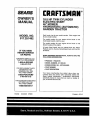
OWNER'S MANUAL
®Assembly
Operation
Customer Responsibilities
®Service and Adjustments
®Repair Parts
CAUTION:
Read and follow
all safety rules and instructions
before operating
this equipn
FOR CONSUMER ASSISTANCE HOT LINE, C_LL THIS TOLL FREE NUMBER: 1,800-659-5917
IIIIIIIIIIIIIIIIIIIIIIIIIIIIIII
................................................
i_':
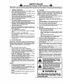
SAFETY RULES
_
Safe Operation Practices for Ride-On Mowers
IMPORTANT: THIS CUTTING MACHINE IS CAPABLE OF AMPUTATING HANDS AND FEET AND THROWING OBJECTS,
FAILURE TO OBSERVE THE FOLLOWING SAFETY INSTRUCTIONS COULD RESULT 1N SERIOUS INJURY OR DEATH.
!.
'
•
•
•
•
°
°
•
•
•
°
•
•
•
•
II,
GENERAL OPERATION
Read, understand, .and follow all Instruct_on_-_the manual
and on the mach{he before starting.
_.
Only allow responsible adu{ts, who are familiar with the
Instructions, to operate the machine_
,.
Clear the area of objects such as rocks, toys, wire, etc.,
which could be picked up and thrown by the blade.
Be sure the areaisclear of otherpeople before mowing Stop
machine if anyone enters the area.
Never carry passengers.
Do not mow in reverse unlessabsolutely necessary. Always
look down and behind before and while backing,
Be aware of the mower discharge direction and do not point
It at anyone. Do not operate the mower without either the
entire grass catcher or the guard in place.
Slow down before turning.,
Never leave a running machine unattended, Always turn off
blades, set parking brake, stop engine, and remove keys
before dismounting.
"rum off blades when not mowing.
Stop engine before removing grass catcher or' unclogging
chute.
Mow only in daylight or good artificiallight.
Do not operate the machine while under the influence of
alcohol or drugs.
Watch for traffic when operating near or crossing roadways.
Use extra care when loading or unloading the machine Into
a trailer or truck
ill.
_r_gtc accidents can occur if the operator is not alert to the
presence of children.
Children are often attracted to the
machine and the mowing activity.
Never assume that
children will remain where you last saw them.
•
Keep children out of the mowing area and underthe watchful
care of another responsible adulL
•
Be alert and turn machine off if children enter the area_
•
Before and when backing, look behind and down for small
children_
•
Never carry children., They may fall off and be seriously
injured or interfere with safe machine operation°
•
Never allow children to operate the machine,.
°
Use extra care when approaching blind corners, shrubs,
trees, or other objects that may obscure vision.
IV. SERVICE
•
•
°
•
•
•
Use extra care in handlinggasoline and other fuels.. They are
flammable and vapors are explosive_
Use only an approved container.
Never remove gas cap or add fuel with the engine
running, Allow engine to cool before refueling, Do not
smoke.
Never refuel the machine indoors.
Never store the machine or fuel container inside where
there is an open flame, such as a water heater.
Never run a machine inside a closed area_
Keep nuts and bolts, especially blade attachment bolts, tight
and keep equipment in good conditlon_
Never tamper with safety devices. Check their proper
operation regularly
Keep machine free ofgrass, leaves, or other debris build-up.
Clean 0il or fuel spillage.. Allow machine to cool before
storing_
Stop and inspect the equipment if you stdke an object.
Repair, if necessary, before restarting.
Never make adjustments or repairs with the engine running.
Grasscatcher componentsare subject towear, damage, and
deterioration, which could expose moving parts or allow
objects to be thrown. Frequently check components and
replace with manufacturer's recommended parts, when necessary.
Mower blades are sharp and can cuL Wrap the blade(s) or
wear gloves, and use extra caution when servicing them.
Check brake operation frequently_ Adjust and service as
required_
•
°
SLOPE OPERATION
°
Slopes are a major factor related to loss-of-control
and
tipover accidents, which can result in severe injury or death.
All slopes require extra caution, if you cannot back up the
slope or if you feel uneasy on it, do not mow it.
DO:
•
°
•
CHILDREN
°
•
Mow up and down slopes, not across.
Remove obstacles such as rocks, tree limbs, etc.
Watch for holes, ruts, or bumps. Uneven terrain could
overturn the machine. Taft grass can htde obstacles.
Use slow speed. Choose a !ow gear so that you wilfnot have
to stop or shift while on the slope.
Follow the manufacturer's recommendations for wheel
weights or counterweights to improve stability,.
Use extra care with grass catchers or other attachments.
These can change the stability of the mactltne.
Keep all movement on the slopes slowand gradual Do not
make sudden changes In speed or direction.,
Avoid starting or stopping on a slope. If tires lose traction,
disengage the blades and proceed slowly straight down the
slope,
•
•
•
•
DO NOT:
°
Do not turn onslopes unlessnecessary and then, turnslowly
and gradual y downhil, if possible.
°
Do not mow near' drop-oils, ditches, or embankments. The
mower could suddenly turn over if a wheel is over the edge
of a cliff or ditch, or if an edge caves in.
•
Do not mow on wet grass. Reduced traction could cause
sliding..
•
Do not try to stabilize the machine by putting your foot or} the
ground.
°
Do not use grass catcher on steep slopes.
I
"
i
!
&
Look for this symbol to point out im"'
I
I
CAUTION!!!
portant
safetyBECOMEALERTt!!
p_ecautions.
It means
YOUR
SAFETY IS INVOLVED.
.....................
,iHi,Ui/.==l
I=l =l= I=l
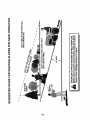
CAUTION: Always disconnect spark plug
spark plug In order to prevent accidental
wireand place wirewhereit cannot contact
starting when setting up, transporting,
adjusting or making repairs.
& WARNING A
2
.....
The engine exhaust from this product contains ct_emicals known to the State of California to cause cancer, birth defects, or other
reproductive harm.
........................................
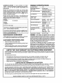
PRODUCT SPECIFICATIONS
CONGRATULATIONS
on your purchase
of a Sears
Tractor.
It has been designed, engineered and manufactured to give you the best possible dependability
and
performance.
HORSEPOWER:
GASOLINE CAPACITY
AND TYPE:
Should you experience
any problem you cannot easily
remedy, please contact your nearest Sear_ Authorized
Service Center/Department
Department.
V_h.ave competent, well-trained
technicians
and the prol_ertools
to
service or repair this tractor.
,;.
Please read and retain this manual. The instructions wil!
enable you to assemble and maintain your tractoi-properly.
Always observe the "SAFETY RULES".
MODEL
NUMBER
DATEOFPURCHASE
THE MODELAND SERIALNUMBERS WILLBE FOUND
ON A PLATE UNDER THE SEAT.
YOU SHOULD RECORD BOTH SERIAL NUMBER AND
DATE OF PURCHASE
AND KEEP IN A SAFE PLACE
FOR FUTURE REFERENCE.
MAINTENANCE
AGREEMENT
RESPONSIBILITIES
o
Read and observe the safety rules°
°
Foltow a regular schedule in maintaining, caring for and
using your tractor.
Follow the instructionsunder "Customer Responsibilities" and "Storage" sections of this owner's manual°
°
SAE30 (above 32°F)
SAE 5W_30 (below 32°F)
OiL CAPACITY:
W/FILTER:
4.0 PINTS
W/O FILTER: 3_5 PINTS
SPARK PLUG:
(GAP: ,025")
CHAMPION RV17YC
VALVE CLEARANCE:
INTAKE:
_003"- _006"
EXHAUST: ,.013" - ,016"
GROUND SPEED (MPH):
FORWARD;
REVERSE:
TIRE PRESSURE:
FRONT:
REAR:
CHARGING SYSTEM:
15 AMPS @ 3600 RPM
BATTERY:
AMP/HR:
MIN_ CCA:
CASE SIZE:
BLADE BOLT TORQUE:
30-35 FT. LBS.
0- 5,7
0- 2_t
14 PSt
10 PSI
30
240
U _R
WARNING: This tractor is equipped with an internal
combustion engine and should not be used on or near any
unimproved forest-covered, brush-covered or grass-cow
ered land unless the engine's exhaust system isequipped
with a spark arrester meeting applicable local or state laws
(if any)° If a spark arrester is used, it should be maintained
in effective working order by the operator.,
In the state of California the above is r_.quired by law
(Section 4442 of the California Public Resources Code)°
Other states may have similar laws. Federal laws apply on
federal lands. A spark arrester for the muffler is available
through your nearest Sears Authorized Service Center/
Department (See REPAIR PARTS section of this manual)..
A Sears Maintenance Agreement is available on this product. Contact your nearest Sears store for details°
CUSTOMER
, 3.5 GALLONS
UNLEADED REGULAR
OIL TYPE (API_SF/SG):
917.251492
SERIAL
NUMBER
185
LIMITED TWO YEAR WARRANTY ON CRAFTSMAN RIDING EQUIPMENT
For two (2) years from the date of purchase, if thisCraftsman Riding Equipmentis maintained, lubricatedand tuned up according
to the instructions in the owner's manual, Sears will repair or replace, free of charge, any parts found to be defective in material
or workmanship.
This Warranty does not cover:
°
o
°
°
Expendable items which become worn during normal use, such as blades, spark plugs, air cleaners, belts, etc.
Tire replacement or repair caused by puncturesfrom outside objects,such as nails,thorns, stumps, or glass.
Repairs necessary because of operator abuse, negligence, improper storage or accidentor the failure to maintain the
equipment according to the instructions contained in the owner's manual..
Riding equipment used for commercial or rental purposes.
LIMITED 90 DAY WARRANTY ON BATTERY
For ninety (90) days from date of purchase, if any battery included wilh this riding equipment proves defective in material or
workmanship and our testing determines the battery will not hold a charge, Sears will replace the battery at no charge.
IN-HOME WARRANTY SERVICE ON YOUR CRAFTSMAN RIDING EQUIPMENT iS AVAILABLE AT NO-CHARGE FOR 30
DAYS FROM THE DATE OF PURCHASE. PLEASE CONTACT YOUR NEAREST SERVICE CENTER, AFTER 30 DAYS
FROM THE DATE OF PURCHASE, WARRANTY SERVICE IS AVAILABLE BY TAKING YOUR CRAFTSMAN RIDING EQUIPMENT TO YOUR NEAREST SEARS SERVtQE CENTER. (IN-HOME "WARRANTY SERVICE WILL STILL BE AVAILABLE
AFTER 30 DAYS FROM THE DATE OF PURCHASE BUT. A STANDARD TRIP CHARGE WILL APPLY.) THIS WARRANTY
APPLIES ONLY WHILE THIS PRODUCT IS IN THE UNITED STATES.
Thts Warranty gives you speciftc legal dghts, and you may also have other rights which may vary from state to state.
SEARS, ROEBUCK
AND CO., D/817 WA, HOFFMAN
3
ESTATES,
IL 60179
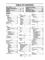
TABLE OF CONTENTS
MAINTENANCE SCHEDULE ..................................... 17
SERVICE AND ADJUSTMENTS .......... ................. 21-27
STORAGE ............. ;..................................................... 28
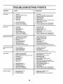
I_'TROUBLESHOOTING ........................................... 29-30
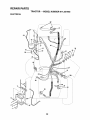
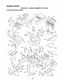
REPAIR PARTS - TRACTOR ................................ 32-47
REPAIR PARTS - ENGINE .................................... 51-60
RARTS ORDERINGtSERVICE ............... BACK COVER
SAFETY RULES ............................................................
2
PRODUCT SPECIFICATIONS
......................................
3
CUSTOMER
RESPONSIBILITIES
................ .:.. 3, 17-20
WARRANTY
...........................
,........ :........... _;., ....... ,..3
TRACTOR ACCESSORIES
.......................... _. ............. 5
ASSEMBLY ...................................................
_........ 7-10
OPERATION .....................................
,; .......... ._,.=... 11-16
INDEX A
E
Operation ..................................................
11-16
Electrical:
Accessories ..........................................................
5
Operating Mower ........................................
14
Interlocks and Relays ..........................
26
Adjustments:
Options:
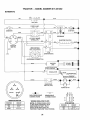
Schematic ..................................... 31
Brake .................... _........................ 23
Accessories ..................................................
5
Wiring Diagram ............................. 32
Carburetor .........................................27
Spark Arrestor ............................ 3,40
Engine:
Clutch Pulley .................................. 23
Air Filter........................................ 19
Gauge Wheels ...... ............................
14
P
Air Screen .......................................
L............19
Mower
Parking
Brake
.........................................
12
Front-To-Back ......................... 22
Cooling Fins ................................. 20
Parts Bag ................................................. 6
Side-To-Side ............................ 21
Oil Change ........................................19
Oil Level .......................................... 15
Throttle Control Cable .................. 27
Parts, Rep[acemenURepair °........... 31-47
Oil Type ..............................................
19
Air Filter; Engine ......................................20
Product Specifications ...............................3
Preparation .................................. 14
Air Screen, Engine ....................................
20
Repair Parts .....................................
51-60
R
Assembly ............................................. 7-10
Starting..........................................................
15
Repair Parts ........................................31-47
Storage ......................................... 28
B
F
S
Battery:
Charging ...................................................
8
Filter:.
Safety Rules .............................................. 2
Cleaning .......................................... 20
Air Filter ...................................................................
_ 20
Seat ...................................................................
8
Starting with Weak Battery .......... 25
Fuel .................................................. 20
Service
and
Adjustments
.................2t-27
Oil .............................................................
20
Storage ..............................................27
Carburetor ..................................... 27
Terminals ...................................... 18
Fuel:
Clutch Pulley .............................................
23
Belt:
Storage ............................................28
Fuse .............................................................
26
Motion Drive
Type ..............................................................
t5
Hood Removal/Insta_|ation ................
26
RemovatlReplacement .............24
Fuse ............................................................
26
Motion Drive Belt
Mower Drive
Removal/Replacement ............ 24
Removal/Replacement ........... 22
Mower Ddve Belt
H
Mower Blade Ddve
Removal/Replacement ............ 22
Headlights ............................................... 26
Removal/RePlacement .............23
Mower Blade Drive Belt
Blade:
Hood Removal/Installation ...........................
26
Removal/Replacement ...............
23
Sharpening ...................................................
18
Mower Adjustment
Replacement ................................... t8
L
Front-to-Back ........................... 22
Side-to-Side ...................................
21
Brake Adjustment ................................. 23
Leveling Mower Deck .............................21
Mower Removal/installation .......... 21
Lubrication:
Tire Care .................................... 8,25
C
Chart ............................................ 17
Slope Guide Sheet .............................. 63
Carburetor Adjustment .............................
27
Engine ......................................................
19
Spark Plug(s) ........................................ 20
Clutch Pulley .......................................... 23
Specifications
M
Controls, Tractor ......................................12
Starting the Engine
15
Maintenance
Schedule
...........................
17
Customer Responsibilities ............. 17-20
Steering Wheel ................................ 7,24
Mower:.
Engine:
Air Filter ................................................
20
Adjustment, Front-to-Back ........... 22
Stopping the Tractor ................................
13
Air Screen ................................... 19
Adjustment, Side-to-Side ................21
Storage ................................................... 28
Blade ReplacEment ..................... 18
Cooling Fins ................................ 20
Blade Sharpening ......................... 18
Engine Oil ............................ 15,19
T
Fuel Filter ........................................
20
Cutting Height .........................................
13
Throttle
Control
Cable
Adjustment .......27
installation ...............................................
21
Spark Plug(s) ..................................
20
Tractor:
Operation ...................................... 14
Tires ....................................................................
8,18,25
Removal ....................................... 2t
Battery ....................................... 18
Troubleshooting Chart .................... 29_0
Blade ............................................ 18
Mowing Tips ......................................... I6
Transaxle ...................................................
i19
Lubrication Chart ....................... 17
:
Muffler
........................
. ............._................ 20
Maintenance Schedule ............ 17
Spark Arrester':_...................................
3,40
W
Tire Care .................................
8,18,25
TransaxIe ...........................................
19
Warranty .................................................... 3
0
Cutting Height, Mower ................................
13
Widng Diagram ...................................... 32
Oil:
Wiring Schematic .................................. 31
Cold Weather Conditions ........ 15,19
.............................................................
3
..................................
Engine .....................................................
19
Storage
...................................................
28
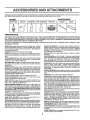
4
AND ATTACHMENTS
These accessories and attachments were available throughmost Sears retail outlets and service centers when the tractor was purchased
Most Sears stores can order these items for you when you provide the model number of your tractor.
_AINTENANCE
ENGINE
GAS CAN
SPARK PLUG
PERFORMANCE
ENGINEOIL
FUEL STABILIZER
AIR FILTER
BLADES
BELTS
r'
Sears offersawide variety of attachments that fit yourtractor.,Many of these are listed below with brief explanations of how they can heiR
you° This list was current _t the time of publication;however, it may change tnfuture yea_ _more attachments may be added, change_
may be made in these attachments, or some may no longer be available or fit your model, Contact your nearest Sears store for the
accessories and attachments that are available for your tractor°
Most of these attachments do not require additional hitches or conversion kits (those that do are indicated) and are designed for easy
attaching and detaching_
SLEEVE CULTIVATOR Is 43 Inches wide. Prepares ground for
seeding, helpsweed control,Steel frame holds 5 adjustable sweeps.
Adjusts vertically,horizontally, (Requires sleeve hitch,) Optional
accessory: steel furrow opener for wider openings for potatoes,
corn,and other deep-seeded crops,
SLEEVE HITCH for use withmasterliftsystem Single pin couples/
uncouples,
SNOWTHROWER has 42-_nch swath, Drum-type auger handles
powderyandwet/heavy snow. Mountseasilywithsimple pin arrangement, Dischargechute adjustsfrom tractor seat, 6-inch diameter
spoutdtschargessnow 10 to 50 feet,, Liftcontrolledat tractorseat,
(Use with chainsand wheel weightsand/or rear drawbar weight.)
SPRAYERS use 12-voltDC electricmotor that_onnectstothe tractor
battery or other 12wolt soume, Includes booms for automatic
spraying and hand held wandfor spot spraying° Wand has adjustable
spraypattern. For applying herbicides, insecticides, fungicides and
liquid fertilizers°
SPREADER/SEEDERS make seeding, fertltiztng, and weed killing
easy. Broadcast spreaders are also useful for granular de-icers and
sand.
AERATOR promotes deep root growth for a healthy lawn.. Tapered
2,5-inch steel spikes mounted on lO-inch diameter discs puncture
holes insoll at close intervals to let moisture soak in Steelwetght tray
for increasedpenetration,
BUMPER protects front end of tractor from damage.
CARTS make haultng easy. Variety of sizes available, plus accessories such as side panel kits, tool caddy, cart cover, protectivemat and
dolly.
CORING AERATOR takes small plugs out of soil to allow moisture
and nutrients to reach grass roots. 36-inch swath. 24 hardened steel
coring tips. !50 tb. capacity weight tray.
DISC HARROW has 2 gangs of 4 steel blades that angle from 10 to
20 degrees, 40 inches wide Can hook 2 units in tandem. (Requires
sleeve hitch,)
DOZER BLADE removes snow; grades dirt, sand and gravel, 48
incheswide, 17 incheshigh, clears44-tnch pathwhenangled,Master
liftcontrol lever for operatorease, Spring trip for snow removal on
uneven pavement; built-in float for blade to follow groundcontour.
Reversible,replaceablescraper bar, (Use withtire chainsend wheel
welghtsand/or rear drawbar welghto)
EASY OIL DRAIN VALVE makes oil changes easier, faster.
FRONT NOSE ROLLER canters in front of mower deck to reduce
chances of "scalping" on uneven terrain.
GANG HITCH lets you tow 2 or 3 pull-behind attachments at
once, such as sweepers, dethatchers, aerators (not for use with
rollers, carts or other heavy attachments)_
MULCH RAKE/DETHATCHER loosens soi! and flips thatch and
matted leaves to lawn surfacefor easy pickup Twentyspringline
teeth°Usefulto preparebare areas for seeding. Available forfront or
rear mounting. HIGH PERFORMANCE REEL-ACTION SPRING
TINE DETHATCH ER covers36-inchwidepath andtossesthatchinto
large hopper, Mounts behind tractor
PLOW turnssoil 6 inchesdeep, cuts 10-]nch furrow, Crank adjustmentcontrolsdepth, 3-positionyokesetswidth. Heavysteel landside
for straightfurrowing° (Requiressleeve hitch,)
RAMP TOPS AND FEET let you load and.unload tractorfrom a
_.pickuptruck, Use with 2x 8 or2 x 10 lumber,
REAR GRADER BLADE is42 Inches wideand operatedfrom driver's
seal Revers_le steelblade can be angled at 30 degreesforgrading_
Reversesfor pushingsnow backwards, (Requiressleeve hitch)
ROLLER for smootherlawn surface. 36-1nchwide, 18-inchdtameter
water-tightdrum holds up to 390 lbs_ of weight. Rounded edges
preventharm to turf, Adjustable scraper automaticallycleans drum
SWEEPERS let you collect grass clippings and leaves.
TILLER has 8 hp engine to prepare seed beds, cultivate, and compost
garden residue. Chain-drive transmission.Six 11-inch diameterone
piece heat-treated steel tines. T_lls 30-inch path. (Requires sleeve
hitch°) Oruse 5 hp tow-behind TILLER with 36-Inch swath to prepare
seed beds, cultivate and compost garden residue. Tiller has its own
built-in itff and depth controlsystem and does NOT require a sleeve
hitch. Fits any lawn, yard or garden tractor, Simply hook up to the
tractor drawbar and go! Optional accessories for 5 hp tiller convert
unit for dethatchtng,aerating, htllingo..without
tools,
TIRE CHAINS are heavyduty; closelyspacedextra-largecrossIinks
give smooth ride, outstandingtraction,
TRACTOR CAB has heavydutyvinylfabric over tubularsteelframe,
ABS plasttctop; clear plasticwindshieldoffers360 degree visibility
Hinged metal doors with catch. Keeps operator warm and dry
Remove vinyl sides and windshieldsfor use as sun protector in
summer. Optional aocessorles Include: tinted/tempered solid
safety glass windshieldwith hand operated wiper;, 12-volt amber
cautionlight for mounting on cab top,
VACS for powerfulcollectionof heavy grassclippingsand leaves
Optional wand attachment topickupdebrisin hard-to.reachplaces,
VAC/CHIPPER includesa chipper-shredder,
WEIGHTBRACKET for drawbarforsnow removalapplications,Can
be mounted on front of tractorfor plowlngapplications, Uses (1) 55
Ib°weight,
WHEEL WEIGHTS for rear wheelsprovideneeded tractionfor snow
removalor dozing heavy materials
5
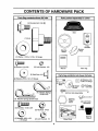
CONTENTS OF HARDWARE PACK
'
iiiii i
..............................
IIIIIIIIjIUlUlLUJ[[IJIIIILIJ
[
Parts Bag contents shown fu!l size
iii
iii
LIIIIII
II1'
ii
Parts packed separately
i
I
I
in carton
,,,,,,,,,,,,,,,,,,,,,,,,,,,,,,, ,,,,,,,,,,,,,,,,,,,,,
(1) Shoulder Bolt 5/16-"_
Seat
Knob!iiY !
Video
Cassette
q
Steering
Wheel
Plate
Mulcher
_
(1) Washer 17/32 x 1-3/16 x 12 Gauge
(2) Lock Washers #10
(2) Screws #10 x5/8
Manual
(2) Weld Nuts #10
(2) Washers 3/16 x 3/4 x 16 Gauge
i
Parts Bag
Parts bag contents not shown full size
J
x 718 x 14 Gauge
\
t_wm(2)
_///(2)
Gauge
Wheels
Q
(2) Centerlock Nuts
Front Link Assemblies
(3) Retainer Springs (double loop)
_/_
u
I_lltlltil{!i!llilllililitf0
u
Wheel
Steering
Insert
(2) Latch Hook
Assemblys
(2) Hex Bolts 1/4-20 x 3/4
(2) Keys
(2) Hex:Nuts 1/4-20
(2) Washers 9132 x 5/8
x 16 Gauge
(2) Lock Washers 1/4
Slope Sheet
6
Steering
Sleeve
LY
....
i1,, ,i,,
=H
,...
i,,
i,,i
inlnmm
,.,,,,,.,.,
..........
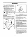
Your new tractor has been assembled at the factory with exception of those parts left unassembled for shipping purposes,,
To ensure safe and proper operation of your tractor all parts and hardware you assemble must be tightened securely. Use
the correct tools as necessary to insure prop_ertightness.
TOOLS
REQUIRED
FOR ASSP_._BLY
&
.-_ STEERtNG WHEEL
A socket wrench set wi!l make assembly easie_i, Standard
wrench sizes are listed.
(2) 7/16" wrenches
(1) Tire pressure gauge
(1) 9/16" wrench
('1) t/2" wrench
(1) Utility knife
(1) 3/4" socket w/drive ratchet
INSERT
.,_p HEX
BOLT
LOCK
,_._ WASHER
LARGE FLAT
When right or left hand is mentioned in this manual, it
means when you are in the operating position (seated
behind the steering wheel)_
TO REMOVE
UNPACK
TRACTOR
FROM CARTON
CARTON
o
Remove all accessible loose parts and parts cartons
from carton (See page 6).
o
Cut, from top to bottom, along lines on all four comers
of carton, and lay panels flat.
°
Remove mower and packing materials°
°
Check for any additional loose parts or cartons and
remove.
wttt=P..LADAPTER
_
/
/
|
__.__
/
t
_/ I
/
t
BEFORE ROLLING TRACTOR OFFSKID
/
t
ii
_,
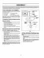
ATTACH STEERING
°
°
SLEEVE
/
!
/
I
WHEEL (See Fig. 1)
FIG. 1
Remove hex bolt, lock washer and large flat washer
from steering shaft°
Position front wheels of the tractor so they are pointing
straight forward_
TO ROLL TRACTOR OFF SKID (See Operation section for location and function of controls)
°
Slide the steering sleeve over the steedng shaft°
°
Position steering wheel so cross bars are horizontal
(left to right) andslide onto steering wheel adapter.
•
°
Secure steering wheel to steering shaft with hex bolt,
lock washer and large fiat washer previously removed.
Tighten securely.
-
°
/ STEERING
, ;;o'
•
Snap steering wheel insert into center of steering
wheel.
°
°
Remove protective plastic from tractor hood and grill
IMPORTANT: CHECK FOR AND REMOVE ANY STAPLES
IN SKID THAT MAY PUNCTURE TIRES WHERE TRACTOR
IS TO ROLL QFF SKID,
7
Press lift lever plunger and raise attachment lift lever to
its highest position.
Release parking brake by depressing clutch/brake
pedal.
Place freewheel control in freewheeling position to
disengage transmission (See 'q'O TRANSPORT" in
the Operation section of this manual).
Roll tractor backwards off skid.
ASSEMBLY
HOW TO SET UP YOUR TRACTOR
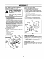
INSTALLSEAT (See Fig. 3)
CONNECT
Adjust seat before tightening adjustment knob.
Remove cardboard packing on seat pan_
ii_
BATTERY
(See Fig. 2)
nals. Before connecting batte_, reCAUTION:
move
metalDo bracelets,
not short battery_ermiwristw_t¢h
bands, rings, etc.
=
Place seat on seat pan and assemble shoulder bolt.
Assemble adjustment knob and flat washer ioosely,
Do not tighten_
o
Tighten shoulder bolt securely.
Positive te_-minal must be connected
first to prevent sparking from accidental grounding.
°
°
Lower seat intooperating position and sit on seat°
Slide seat until acomfortable position is reached which
allows you to press clutch/brake pedal all the way
down,
•
Get off seat without moving its adjusted position,
HIIH III
I
LI
I I
II
•
Lift hood to raised position_
•
Open terminal access doors, remove terminal protective caps and discard;
°
if this battery is put into service after month and year
indicated on label (label located between terminals)
charge battery for minimum of one hour at 6-10 amps.
•
Raise seat and tighten adjustment knob securely°
SEAT
First connect RED battery cable to positive (+) battery
terminal with hexbolt, flat washer, lock washer and hex
nut as shown. Tighten securely.
SEAT PAN
SHOULDER
BOLT
•
Connect BLACK grounding cable to negative (-) battery terminal with remaining hex bolt, flat washer, lock
washer and hex nut. Tighten securely.
Close terminal access doors.
Use terminal access doors for:
°
Inspection for secure connections (to tighten hardware).
°
°
Inspection for corrosion.
Testing battery°
°
Jumping (if required).
•
Periodic charging.
,\
FLAT
WASHER
ADJUSTMENT
KNOB
FIG. 3
LOCK
WASHER
HEX NUT
DISCARD TERM,NAL
PROTECTIVE CAPS
"\.
TERMINAL .... ",_
!_/_
\
._
_ "'=""'_/
ACCESS
.'FL.. jj_'J!_,
DOOR _. __<:_
_.._.._/__
.._.JL.=_e
_
v
CHECK TIRE PRESSURE
FLAT
WASHER
The tires on your tractorwere overinflated at the factory for
shipping purposes, Correct tire pressure is important for'
best cutting performance.
•
Reduce tire pressure to PSI shown in "PRODUCT
SPECIFICATIONS" on page 3 of this manual
HEX
BOLT
CHECK BRAKE SYSTEM
_
After you learn how to operate your tractor, check to see
that the brake is properly adjusted. See "TO ADJUST
BRAKE" in the Service and Adjustments section of this
manual
PosmvE
- (RED)
FIG. 2
8
LY
i
rl
II
(See
"
Be sure tractor is on level surface and mowe_suspension
arms are raised with attachment lift control. E_gage parking brake.
'_:
o Cut and remove ties securing anti-sway barand belts°
Swing anti-sway bar to left side of mower deck
Place the R°H_ suspension arm on inward pointing
deck pin. If necessary', rock and raise front of mower
to align deck pin with the hole in suspension arm
Retain with double loop retainer spring with loops
down as shown.
.
Connect anti-sway bar to chassis bracket under left
footrest and retain with double loop retainer spring°
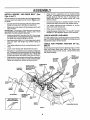
INSTALL MOWER _'_
AND DRIVE BELl:
Figs. 4 and 7)
=
Slide mower undertractorwith discharge guardto right
side of tractor,
IMPORTANT: CHECK BELt FOR PROPER ROUTING IN
ALL MOWER PULLEY GROOVES. INSTALL BELT INTO
ELECTRIC CLUTCH PULLEY GROOVE,
Turn height adjustment knob clocl_vise to remove
slack from mower suspensiono
°
°
Raise mower to highest position°
Assemble gauge wheels (See "TO ADJUST GAUGE
WHEELS" In the Operation section of this manual).
°
CHECK MOWER LEVELNESS
•
o
Install one front link in top hole of the R.H. front mower
bracket and R.H. front suspension bracket° Retain with
two single loop retainer springs as shown.
tnstail secondfront linkin L,H. front suspensionbracket
only and retain with single loop retainer spring as
shown°
=
Turn height adjustment knob counterclockwise until it
stops.
°
°
Lower mower linkage with attachment lift control.
Placethe L.H. suspension arm on inward pointing deck
pin. If necessary, rock and raise front of mower to align
deck pin with the hole in suspension arm° Retain with
double loop retainer spring with loops down as shown.
Slide left Side of mowerback and install the unattached
front link in top hole of the L.H, front mower bracket_
Retain with single loop retainer spring as shown.
=
CHASSIS
BRACKET
DOUBLE LOOP
RETAINER SPRING
(inward pointing
deck pins)
For best cuttingresults mower should be properly leveled,
See 'qrO LEVEL MOWER HOUSING" in the Service and
Adjustments section of this manual.
CHECK
BELTS
FOR PROPER
POSITION
OF ALL
See the figures that are shown for replacing motion, mower
ddve, and mower blade drive belts in the Service and
Adjustments section of this manual Verify that the belts
are routed correctly.
FRONT
SUSPENSION
BRACKETS"
ELECTRIC
CLUTCH
PULLEY'
SUSPENSION
ARMS
FRONT
MOWER
BRACKET
FRONT
LINK
SHOULDER
BOLT
GAUGE
WHEEL
SINGLE
LOOP
RETAINER
SPRINGS
/
3/8 WASHER
USE PLIERS FOR
RETAINER SPRINGS
31846
CENTER
LOCKNUT
DOUBLE LOOP
RETAINER
SPRING
ANTI-SWAY
BAR
IDLER /
PULLEY
DISCHARGE GUARD
FIG. 4
9
INSTALL MULCHER PLATE (See Figs. 5 and 6)
DEFLECTOR
SHIELD
*
Install two latch hooks to mulcher plate using screw,
washer, !ock washer, and weld nut as sho_n.
NOTE: Pre-assembIe weld nut to latch hook b_ inserting
weld nut from the top with hook pointingdown_
,
Tighten hardware securely.
o
Raise and hold deflector shield in upright position.
*
=
Place front of mutcher plate over front of mower deck
opening and slide into place, as shown.
Hook front latch into hole on front of mower deck°
°
Hook rear latch into hole on back of mower deck.
LATCH
HOOKS
guard from mower. Raise and hold
CAUTION:
not remove
discharge
guard whenDoattaching
mulcher
plate
and allow it to rest on plate whde in
operation.
FIG. 6
,/CHECKLIST
TO CONVERT TO BAGGING
DISCHARGING
BEFORE YOU OPERATE AND ENJOY YOUR NEW
TRACTOR, WE WISH TO ASSURE THAT YOU RECEIVE
THE BEST PERFORMANCEAND SA TISFA C TION FROM
THIS QUALITY PRODUCT.
OR
Simply remove mulcher plate and store in a safe place.
Your' mower is now ready for discharging or installation of
optional grass catcher accessory.
PLEASE REVIEW THE FOLLOWING CHECKLIST:
NOTE: It is not necessary to change blades. The mulcher
blades are designed for' discharging and bagging also_
HOOK POINTS
DOWN
WELD NUT
FROM THE TOP,
,/
All assembly instructions have been compietedo
v"
,/
No remaining loose parts in carton.
Battery is properly prepared and charged° (Minimum
1 hour at 6 amps).
Seat is adjusted comfortably and tightened securely.
,/
LOCK
WASHER
v"
All tires are properly inflated. (For shipping purposes,
the tires were overinflated at the factory)_
,/
Be sure mower' deck is properly leveled side-to-side/
front-to-rear for' best cutting results_ (Tires must be
properly inflated for leveling),
Check mowerand drive belts. Be sure they are routed
properly around pulleys and inside all belt keepers.
Check widngo See that all connections are still secure
and wires are properly clamped.
SCREW
,f
LATCH
,/
HOOK
J"
\
WASHER
LOCK
WASHER
Before driving tractor, be sure freewheel control is in
drive position.
WHILE LEARNtNG HOW TO USE YOUR TRACTOR, PAY
EXTRA A TTENTION TO THE FOLLOWING IMPORTANT
ITEMS:
WELD
NUT
WASHER
MULCHER
PLATE
,/ Engine oil is at proper level.
4" Fuel tank is filled with fresh, clean, regular unleaded
gasoline.
€" Become familiar with all controls - their location and
function. Operate them before you start the engine.
,/ Be sure brake system is in safe operating condition° _
'_'-'--SCREW
FIG. 5
#"
10
It is importantto purge the transmission before operatingyourtractorfor the first time. Follow proper starting
and transmissionpurginginstructions(See "TO START
ENGINE and PURGE TRANSMISSION in Operation section of this manual),.
............................
.....................................................................
i
i i ,,,ll,,i,,r,jl/,i,j
OPERATm
.....
i,i
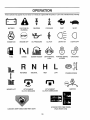
These symbols may appear
ii, ,llullllull,,,,,ill,
:
............................
on your tractor or in 5terature supplied with the product° Learn and understand
they meaning.
BATTERY
CAUTION OR
WARNING
REVERSE
FORWARD
FAST
SLOW
ENGINE ON
ENGINE OFF
OIL PRESSURE
CLUTCH
LIGHTS ON
LIGHTS OFF
FUEL
CHOKE
MOWER HEIGHT
DIFFERENTIAL
LOCK
PARKING BRAKE
LOCKED
UNLOCKED
L
REVERSE
MOWER LIFT
HIGH
NEUTRAL
ATTACHMENT
CLUTCH ENGAGED
LOW
ATTACHMENT
CLUTCH DISENGAGED
PARKING BRAKE
IGNITION
HYDROSTATIC FREE WHEEL
(Hyd_ Modelsonly)
DANGER, KEEP HANDS AND FEET AWAY
11
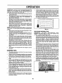
OPERATION
KNOW YouR TRACTOR ...............................................................................
READ THIS OWNER'S
MANUAL AND SAFETY RULES BEFORE OPERATING
YOUR TRACTOR.
Compare the illustrations with your tractor to fa_liarize yourself _ith the location of various controls and adjustments. Save
this manual for future reference.
THROTTLE CONTROL
AMMETER
ATTACHMENT
CLUTCH SWITCH
LIFT LEVER
PLUNGER
CHOKE CONTROL
LIGHT SWR"CH
CLUTCWBRAKE
PEDAL
LIFT LEVER
HEIGHT ADJUSTMENT
KNOB
IGNITION SWITCH
PARKING BRAKE
LEVER
MOTION
CONTROL
LEVER
SPEEDS:
3
2
FREE WHEEL CONTROL
FIG. 7
Our tractors conform to the safety standards of the American National Standards institute°
AMMETER - Indicates charging (+) or discharging (-) of
battery=
HEIGHT ADJUSTMENT KNOB- Used to adjust the mower
cutting height,
ATTACHMENT CLUTCH SWITCH - Used to engage the
mower blades or other attachments mounted to yourtractor.
IGNITION SWITCH - Used for starting and stopping the
engine,
LIFT LEVER PLUNGER - Used to release attachn'lertt
I[_
]ever when changing its position,
CHOKE CONTROL - Used when starting a cold engine.
LIGHT SWITCH - Turns the headlights on and off.
CLUTCH/BRAKE PEDAL - Used for declutching and
braking the tractor and starting the engine,
MOTION CONTROL LEVER - Selects the speed and
direction of the tractor,
FREEWHEEL CONTROL - Disengages transmission for
pushing or slowly towing the tractor with the engine off.
PARKING BRAKE LEVER - Locks clutch/brake pedal into
the brake position.
12
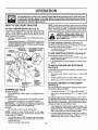
O
The operation of any tractor can result in foreign objects thrown into the eyes, which can result
in severe eye damage. ALways wear safe_y glasses or eye shields while operating your tractor
or performing any adjustments or repair_ We recommend a wide vision safety mask over the
spectacles or standard s_ty glasses.
HOW
TO USE YOUR
TO SET PARKING
NOTE: Under certain conditions when tractor is standing
idle with the engine running, hot engine exhaust gases may
cause "browning" of grass. To eliminate this possibility,
always stop engine when stopping tractor on grass areas.
TRACTOR'
BRAKE (See Fig, 8)
Your tractoris equipped withan operator presencesensing
switch. When engine is running, any attempt by the
operator to leave the seat without first setting the parking
brake will shut off the engine°
.
Depress clutch!brake pedal intofull "BRAKE" position
and hold.
o Place parking brake lever in ,ENGAGED" position ancl
releasepressure from clutch/brake pedal. Pedalshouid
remain in"BRAKE" position,. Make sure parking brake
witl hold tractor secure°
PUSH IN TO
THROTTLE
"DISENGAGE"
CONTROL LEVER
i
pletely, as described above, before leaving the operator's position; to empty
CAUTION:
Always
grass catcher,
etc. stop tractor com-
TO USE CHOKE CONTROL
(See Fig. 8)
Use choke control whenever you are starting a cold engine_
Do not use to start a warm engine.
° To engage choke control, pull knob out Slowly push
knob in to disengage.
ATTACHMENT CLUTCH
SWITCH PULL OUT TO
TO USE THROTTLE
CHOKE
CONTROL
(See Fig. 8)
Always operate engine at full throttle.
,, Operating engine at less than full throttle reduces the
battery charging rate.
o Full throttle offers the best bagging and mower performance°
CONTROL..,_
CLUTCH/BRAKE
PEDAL "BRAKE"
POSITION
TO MOVE FORWARD
IGNITION
AND BACKWARD
(See Fig. 8)
The directionand speed of movement is controlled by the
motion control lever°
MOTION
CONTROL
LEVER
"DRIVE"
POSITION
HEIGHT
ADJUSTMENT
KNOB
"DISENGAGED ....
POSITION
PARKING
BRAKE
ENGAGED"
POSITION
°
Turn ignition key to "OFF" position and remove key.
Always remove key when leaving tractor to prevent
unauthorized use.
Never use choke to stop engine.
-
Release parking brake and clutch/brake pedal.
Slowly move motion control lever io desired position,.
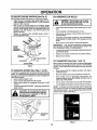
HEIGHT
The cutting height is controlledby turning the height adjustment knob in desired direction.
(See Fig. 8)
MOWER BLADES °
Move attachment clutch switch to "DISENGAGED"
position.
GROUND DRIVE = Depress clutch/brakepedal into fu]I"BRAKE" position,
° Move motion controllever to neutral (N) position_
IMPORTANT: THE MOTION CONTROL LEVER DOES
NOT RETURN TO NEUTRAL (N) POSITION WHEN THE
CLUTCH/BRAKE PEDAL IS DEPRESSED,
i_ENGINE °
Move throttle control to slow (.ga_) position,.
NOTE: Failure to move throttle contr'0l to slow (._)
position and allowing engine to idle before stopping may
cause engine to "backfire".
•
Start tractor with motion control lever in neutral (N)
position°
TO ADJUST MOWER CUTTING
(See Fig. 8)
FIG. 8
STOPPING
o
•
Turn knob clockwise (f-_) to raise cutting heighL
-
Turn knob counterclockwise
height.
(l,'_)to
lower cutting
The cut'dng height range is approximately 1°1t2" to 4°1/2".
The heights are measured from the ground to the blade tip
with the engine not running. These heights are approximate and may vary depending upon soit conditions, height
of _rass and types of grass being mowed,,
= The average tawn should be cut to approximately 2-1!2
inches during the cool season and to over 3 inch_s
_lbring hot months° For healthier and better Iookihg
lawns, mow often and 'after moderate growth.
°
'13
For best cutting performance, grass over 6 inches in
height should be mowed twice. Make the first cut
relatively high; the second to desired heighL
OPERATION
ii
TO ADJUST
GAUGE WHEELS
Adjust gauge wheels with tractor on a flat level surface.
= Adjust mower to desired cutting height (S_e '_,O ADJUST MOWER CUTTING HEIGHT" in the*Operation
section of this manual)_
° With mower in desired height of cut position, gauge
wheels should be assembled so they are slightl_ off the
ground. Install gauge wheel in appropriate hole with
shoulder bolt, 3/8 washer, and 3/8-16 locknut and
tighten securely.
•
Repeat for opposite side installing gauge wheel in
same adjustment hole.
QUAKE
WHEEL
,_..\__//
318-16
LOCKNUT
3/8WA
_,_,_
H
hills with slopes greater than 15° and
...............
CAUTION: Do not drive up or down
do not drive across any slope.
I
•
Choose the slowest speed before starting up or'down
hills.
•
Avoid stopping or changing speed on hills.
•
If slowing is necessary, move throttle control lever to
slower position.
•
If stoppingis absolutely necessary, push clutch/brake
pedal quickly to brake position and engage parking
brake.
I!
°
To restart movement,slowlyrelease parking brakeand
clutch/orake pedal.
°
Slowly move motion controllever to slowest setting,
°
Make all turns slowly.
(See Figs. 7 and 11)
When pushing or towing yourtractor, be sure to disengage
transmissionby placingfreewheel contro! in freewheeling
position_Free wheel controlis located at the rear drawbar
of tractor.
FIG. 9
MOWER (See Figs. 7 and 8)
•
Your tractor is equipped withan operatorpresencesensing
switch. Any attempt by the operator'toleave the seat with
the engine runningand the attachment ciutchengaged will
shut off the engine_
° Select desired height of cut.
° Lower mower with attachment lift control,
•
Start mower btades by engaging attachment ctutch
control°
° TO STOP MOWER BLADES_ disengage attachment
clutch control
J '&
li_
TO TRANSPORT
/_----/"'_
GAUGE WHEEL
TO OPERATE
II
°
Move motion control lever to neutral (N) position°
IMPORTANT: THE MOTION CONTROL LEVER DOES
NOT RETURN TO NEUTRAL (N) POSITION WHEN THE
CLUTCH/BRAKE PEDAL IS DEPRESSED,
'(
/I
im
TO OPERATE ON HILLS
(See Fig. 9)
°
Raise attachment lift to highest position with attachment lift control.
Remove retainer spring from freewheel control rod
°
Push control rod in to disengage transmission and
reinsert retainer spring into control rod hole now on
back side of the bracket.
•
•
Do not push or tow tractor at more than two (2) MPH.
To reengage transmission, reverse above procedure,
NOTE: To protect hood from damage when transporting
your tractor on a truck or a trailer, be sure hood ts closed
and secured to tractor. Use an appropriate means of tying
hood to tractor (rope, cord, etc.).
without either the entire grass catcher,
on
mowers Do
so not
equipped,
or the
discAU'T1ON:
opera't'ethe
mower
i
............
charge'guard in place.
. ...
_DISCHARGE
/
//
GUARD
FIG. 10
FIG. 11
14
0
EBATmON
BEFORE STARTING THE ENGINE
TO START ENGINE (See Fig. 8)
When starting the engine for the first time or if the engine
has run out of fuel, it will take extra cranking time to move
fuel from the tank to the engine.
= Depress clutch/brake pedal and set parking brake_
°
Place motion control lever in neutral (N) position_
°
Move attachment clutch to "DISENGAGED" position°
•
Move throttle control to choke (N) position
Note: Before starting, read the warm and cold starting
procedures below.
°
Insert keyinto ignitionand turn keyclockwiseto"START"
position and release key as soon as engine starts. Do
not run starter continuously for more than fifteen seconds per minute_ If the engine does not start after
several attempts, move throttle control to fast (,,_)
position, wait a few minutes and try again. If engine still
does not start, move the throttle control back to the
choke (N) position and retry.
WARM WEATHER STARTING (50° F and above)
° When engine starts, move the throttle control to the fast
(,_) position.
° The attachments and ground drive can now be used_ If
the engine does not accept the load, restart the engine
and allow it to warm up for one minute using the choke
as described above°
COLD WEATHER STARTING ( 50 ° F and below)
° When engine starts, allow engine to run with the throttle
control in the choke (N) position untit the engine runs
roughly, then move throttle Control to fast (,_) position.
This may require an engine warm-up period from
several second._to several minutes, depending on the
temperature.
HYDROSTATIC TRANSMISSION WARM UP
CHECK ENGINE OIL LEVEL (See Fig_,12)
=
The engine in your tractor has been shipped, from the
factory, already filled with summer weight oil
•
Check engine oil with tractor on level ground.
°
Remove oil fill cap/dipstick and wipe clean, reinsert the
dipstick and push it all the way down into the tube, wait
for a few seconds, remove and read oil level. If
necessary, add oil until "FULL" mark on dipstick is
reached_ Do not overfill.
°
For cold weather operation you should change oil for
easier starting (See OIL VISCOSITY CHART" in the
Customer Responsibilities section of this manual).
=
To change engine oil, see the Customer ResponsibiliL
ties section in this manual.
ENGINE OIL
FILL CAP/DIPSTICK
FIG. 12
ADD GASOLINE
°
Fill fuel tank. Use fresh, clean, regular unleaded
gasoline with a minimum of 87 octane. (Use of leaded
,gasoline witt increase carbon and lead oxide deposits
and reduce valve life). Do not mix oil with gasoline.
Purchase fuel in quantities that can be used within 30
days to assure fuel freshness.
IMPORTANT: WHEN OPERATING IN TEMPERATURES
BELOW 32°F(0°C), USE FRESH, CLEAN WINTER GRADE
GASOLINE TO HELP INSURE GOOD COLD WEATHER
STARTING.
,,
Before driving the unit in cold weather, the transmission should be warmed up as follows:
° Be sure the tractor is on level ground_
• Place the motion control lever in neutral°
Release the parking brake and let the clutch/brake
slowly return to operating position.
• Allow one minute for transmission to warm upo
This can be done during the engine warm up
period.
° The attachments can also be used during the engine
warm-up period afterthe transmission has been warmed
up.
NOTE: If at a high altitude (above 3000 feet) or in cold
temperatures (below 32 F) the carburetor fuel mixture may
need to be adjusted for best engine performance. See "TO
ADJUST CARBURETOR" in the Service and Adjustments
section of this manual
WARNING: Experience indicates that alcohol blended
fuels (called gasohol or using ethanol or methanol) can
attract moisture which leads to separation and formation of
acids during storage. Acidic gas can damage the fuel
system of an engine while in storage. To avoid engine
problems, the fuel system should be emptied before storage of 30 days or longer. Drain the gas tank, start the
engine and let it run until the fuel lines and carburetor are
empty. Use fresh fuel next season. See Storage Instructions for additional information.
Never use engine or
carburetor cleaner products in the fuel tank or permanent
damage may occur.
i
i
ill
ii
i
PURGE TRANSMISSION
i
filler neck. Donotoverfill. Wipeoffany
CAUTION:
to Do
bottom
of gas
tank
spilled oil orFill
fuel.
not store,
spill
or
use gasoline near an open flame°
15
To ensure proper operation and performance, it is recommended that the transmission be purged before operating
tractor for the first time. This procedure will remove any
trapped air inside the transmission which may have developed during shipping of your tractor.
......................................................
:
ii ii ii
illllllll
IL
OPERATION
--
_
7 ;
II,N
III
II III
ll'l
,.,.,.,
, ,, ......
IMPOR;rANT: SHOULD YOUR TRANSMISSION REQUIRE
REMOVAL FOR SERVICE OR REPLACEME:NT, IT
SHOULD BE PURGED AFTER REINSTALUATION
BEFORE OPERATING THE TRACTOR.
•
Place tractorsafely on level surface.withengine off and
parking brake set.
°
Disengage transmission by placing freewheel,control
in freewheeling position (See "TO TRANSPORT" in
this section of manual).
= Sitting inthe tractorseat, startengine. Aftertheengine
!s running,move throttlecontrolto slow (,g_) position,
With motion controllever in neutral (N) position,slowly
disengage clutch/brake pedal.
Move motion control lever to full forward position and
hold for five (5) seconds. Move lever to full reverse
position and hold for five (5) seconds. Repeat this
procedure three (3) times,
NOTE; Duringthis procedure there willbe no movement of
drive wheels. The air is being removedfrom hydraulicdrive
system.
•
Move motion controllever to neutral (N) position. Shutoff engine and set parking brake.
° Engage transmission by placing freewheel control in
drivingposition(See "TO TRANSPORT" inthis section
of manual).
.
Sittingin the tractor seat, start engine. After the engine
is running, move throttle control to half (1/2) speed
With motion controllever in neutral (N) position, slowly
disengage clutch/brake pedal.
°
Slowly_move motion control lever' forward, after' the
tractor moves approximately five (5) feet, slowly move
motion control lever to reverse position.. After' the
tractor moves approximately five (5) feet return the
motioncontrollever tothe neutral (N) position. Repeat
this procedure with the motion controllever three (3)
times,
•
Your tractor is now purged and now ready for normal
operation°
•
Always operate engine at full throttle when mowing to
assure better mowing performance and proper discharge of material. Regulate ground speed by selecting a low enough gear to give the mower cutting
performance as well as the quality of cut desired.
° • When operating attachments, select a ground speed
that will suit the terrain and give best performance of
the attachment being used°
f
t
FIG. 13
MULCHING
MOWING TIPS
IMPORTANT:
FOR BEST PERFORMANCE, KEEP
MOWER HOUSING FREE OF BUILT-UP GRASS AND
TRASH, CLEAN AFTER EACH USE.
•
The special mulching blade will recut the grass clippings many times and reduce them in size so that as
they fall onto the lawn they will disperse into the grass
and not be noticed. Also, the mulched grass will
biodegrade quickly to provide nutrients for the lawn.
Always mulch with your•highest engine (blade) speed
as this will provide the best recutting action of the
blades.
= Avoid cutting your lawn when it iswet. Wet grass tends
to form clumps and interferes with the mulching action.
The best time to mow your' lawn is the early afternoon.
At this time the grass has dried and the newly cut area
will not be exposed to the direct sun.
° For best results, adjust the mower cutting height so that
the mower cuts off only the top one-third of the grass
blades (See Fig. 14). For extremely heavy mulching,
reduce your widthof cut on each pass and mow slowly.
° Certain types of grass and grass conditions may require that an area be mulched a second time to completely hide the clippings. When doing a second cut,
mow across or perpendicular to the first cut path,
° Change your cutting pattern from week to week. Mow
northto south one week then change to east to west the
next week. This will help prevent matting and graining
of the lawn.
MOWING TIPS
°
Tire chains cannot be used when the mower housing
is attached to tractor'.
= Mower should be properly leveled for best mowing
performance. See "TO LEVEL MOWER HOUSING" in
the Service and Adjustments section of this manual.
•
The left hand side of mower should be used for trim_
ruing.
•
Drive so that clippings are discharged onto the area
that has been cut, Have the cut area to the right of the
tractor This will result in a more even distributionof
clippingsand more uniformcutting_
•
When mowing large areas, startby turningto the right
so that clippings will discharge away from shrubs,
fences, driveways, etco After one or two rounds, mow
in the opposite direction making left hand turns until
, finished (See Fig. 13).
= tf grass is extremely tail; it should be mowed twice t'o
reduce load and possible fire hazard from dried clippings. Make first cut relatively high; the second to the
desired height.
o, Do not mow grass when it is wet. Wet grass will plug
mo_ver and leave undesirable clumps. Allow grass to
dry before mowing.
MAX 1/3
FIG. 14
16
CUSTOMER
RESPONSmBmLBTIES
AS YOU COMPLETE
REGULARSERVICE
Check BrakeOperation
CheckTire Pressure
T Check
forLoose
Faster,
e,s
__.._"
f
_1'
_1'
_.._ _,_'._ SERVICE
DATES
V _'
°_ ......
_,:
j
v",
v"
C
Check Battery
0
LeveVRecharge
......
v"
CleanBattery and Terminals
Adjust
[
v'
v'
R Check TransaxleCooling
Adjust Blade Belt(s)Tension
......................
V'5
Motion Drive Belt(s) Tension
Check Engine Oil Level
ChangeEngineOil
Clean Air Filter
tb/
V"
_2._
v"
v"2
NEi c{eanA=r
Scree"
G ,,,,,,!,nSPe
ct Muffler/SPark Arrester
IN
E
Replace Oil Ftlter (if equipped)
Clean Engine Cooling Fins
Replace Spark Plug
v' v"
ReplaceAir Filter PaperCartridge
v'
ReptaceFuel Filter
12 3 4 -
Change more often when operating under e heavy load or in high ambient temperatures
Se_cB more often when operating in ditty or dusty conditions
If equipped with oil filter, change oi1every 50 hours
Replace blades more often when mow_ng in sandy soil.
5 - If equipped wilh adjustable system
6 - Not mqutred if equipped with maintenance-free battery.
7 _ Tighten front axle pivot belt to 35 ft -Ibs,, maximum
Do net over_lghten_
GENERAL RECOMMENDATIONS
LUBRICATION
The warranty on this tractor does not cover itemsthat have
been subjected to operator abuse or negligence. To
receive full value from the warranty, operator must maintain
tractor as instructed in this manual
(_)TIE ROD BALL JOINTS
®
Some adjustments will need to be made periodically to
properly maintain your tractor_
®
All adjustments in the Service and Adjustments section of
this manual should be checked at least once each season.
FRONT
BEARING ZERK
®
Once a year you should replace the spark plug, clean
or replace air filter, and check blades and belts for
wear. A new spark plug and clean air filter assure
proper air-fuel mixture and help your engine run better
andlast longer°
BEFORE
CHART
SECTOR GEAR
TEETH
EACH USE
,
Check engine oil level°
o
o
°
Check brake operation.
Check tire pressure.
Check for loose fasteners°
(_) SPRAY SILICONE LUBRICANT (MOVE BOOTS TO LUBRICATE)
IMPORTANT;
DO NOT elL OR GREASE THE PIVOT POINTS
WHICH HAVE SPECIAL NYLON BEARINGS_
VISCOUS LUBRICANTS WILL ATTRACT DUST AND DIRT THAT WILL SHORTEN
THE LIFE OF THE SELF-LUBRICATING
BEARINGS.
IF YOU
FEEL THEY MUST BE LUBRICATED,
USE ONLY A DRY, POWDERED GRAPHITE TYPE LUBRICANT SPARINGLY.
17
®
GENERAL PURPOSE GREASE
®
REFER TO CUSTOMER RESPONSIBILITIES
"ENGINE"
SECTION
CUSTOMER
RESPONSIB!
TRACTOR
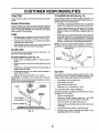
TO SHARPEN
BLADE (See Fig. 16)
_Care should be taken to keep the blade balanced, An
unbalancedblade willcause excessive vibration and eventual damage to mower and engine.
Always observe safety rules when performing any maintenance°
BRAKE OPERATION
=
tf tractor requires more than six (6) feet stoppingdistance
at high speed in highest gear, then brake must be adjusted.
(See "TO ADJUST BRAKE" in the Service and Adjustments section of this manual).
Thebladecanbesharpenedwithafileoronagrinding
wheel. Do not attempt to sharpen white on the mower,
°
TIRES
°
To check blade balance, you will need a 5/8" diameter
steel bolt, pin, or a cone balancer. ('When using a cone
balancer, follow the instructions supplied with balancer).
Slide blade on to an unthreaded portionofthe steel bolt
or pin and hold the bolt or pin parallel with the ground.
If blade is balanced, it should remain in a horizontal
position° If either end of the blade moves downward,
sharpen the heavy end until the blade is balanced.
Maintain proper air pressure in all tires (See "PRODUCT SPECIFICATIONS". on page 3 of this manual)°
Keep tires free of gasoline, oil, or insectcontrol chemicals which can harm rubber.
i
NOTE: Do not use a nail for balancing blade. The lobesof
he center hole may appear to be centered, but are noL
Avoid stumps, stones, deep ruts, sharp objects and
other hazards that may cause tire damage.
o
BLADE CARE
CENTERHOLE
/
/
For best results mower blades must be kept sharp_ Replace bent or damaged blades°
BLADE REMOVAL
(See Fig. 15)
•
Raise mower to highest position to allow access to
blades.
I
Remove hex boIt, tock washer and flat washer securing
blade.
o
Install new or resharpened blade with trailing edge up
towards deck as shown.
=
FIG. 16
Reassemble hex bolt, lock washer and flat washer in
exact order as shown°
BATTERY
Your' tractor has a battery charging system which is sufficient for normal use. However, periodic charging of the
battery with an automotive charger will extend its life.
° Keep battery and terminals clean.
° Tighten bolt securely (30-35 Ft. Lbs. torque),.
IMPORTANT: BLADE BOLT IS GRADE 8 HEATTREATED_
NOTE: We do not recommend sharpening blade- but if you
do, be sure the blade is balanced,
B,
,_
_)_
MANDREL
°
Keep battery bolts tight.
•
°
Keep small vent holes open.
Recharge at 6-10 amperes for 1 hour.
TO CLEAN BATTERY AND TERMIN_ALS
Corrosion and dirt on the battery and _terminalscan cause
the battery to "leak" power.
= Remove terminal guard.
•
-
Disconnect BLACK battery cable first then RED
batter,] cable and remove battery from tractor.
•
°
Rinse the battery with plain water and dry.
Clean terminals and battery cable ends with wire brush
until brighL
Coat terminals with grease or petroleum jelly.
*A GRADE 8 HEAT TREATED BOLT CAN BE
IDENTIFIED BY SIX LINES ON THE BOLT HEAD.
°
FIG. 15
,;
18
Reinstall battery (See "CONNECT BATTERY" in the
Assembly section of this manual)°
,'
CUSTOME
TRANSAXLE
BULUTmES
COOLING
TO CHANGE ENGINE OIL (See Figo17)
Determine temperature range expected before oil change.
All oil must meet API service classification SF or SG
The fan and cooling fins of transmission should be kept
clean to assure proper coolfng_
Do not attempt to clean fan or transmissionwhile engine is
running or while the transmission is hot. To prevent
possibledamage to seals, no not use high pressure water
or steam to clean transaxle.
o
Inspect coolingfan to be sure fan bTadesare intact and
clean.
o
Inspect cooling fins for dirt, grass clippings and other
materials, To prevent damage to seals, do not use
compressed air or high pressure sprayer,
TRANSAXLE
PUMP FLUID
The transaxle was sealed at the factory and fluid maintenance is not required for the life of the transaxte. Should
the transaxle ever leak or require servicing, contact your
nearest authorized service center/department.
V-BELTS
•
Be sure tractor is on level surface°
•
•
Oil wil! drain more freely when warm.
Catch oil in a suitable container°
o
Remove oil fill capidipstick_ Be careful not to allow dirt
to enter the engine when changing oil,
°
°
Remove drain plugo
After oil has drained completely, replace oil drain plug
and tighten securely.
°
Refill engine with oil through oil fill dipstick tube. Pour
slowly. Do not overfill For approximate capacity see
"PRODUCT SPECIFICATIONS" on page 3 of this
manual.
°
Use gauge on oil fill cap!dipstick for checking level. Be
sure dipstick is in all the way for accurate reading,
Keep oil at "FULL" line on dipstick.
OIL DRAIN PLUG
Check V-belts for deterioration and wear after 100 hoursof
operation and replace if necessary. The belts are not
adjustable. Replace belts if they begin to slip from wear.
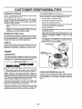
ENGINE
ENGINE OIL
FILLER CAP/DIPSTICK
LUBRICATION
Only use high quality detergent oil rated with API service
classificationSF orSG. Select theoil'sSAE viscositygrade
according to your expected operating temperature°
SAE VISCOSITY
GRADES
FIG. 17
°c -3o
o
-2o"
.........TEMPERATURE
.Io
o
o°
RANGE ANTICIPATED
_o"
2o_
3o•
40'
BEFORE NEXT OIL CHANGE ...........
CLEAN AIR SCREEN
NOTE: Although multi-viscosity oils (5W30, 10W30 etc°)
improve starting in cold weather, these multi-viscosity oils
will result in increased oil consumptionwhen used above
32°F. Check your engine oil level more frequently to avoid
possible engine damage from runninglow on oil.
(See Fig. 18)
Air screen must be kept free of dirt and chaff to prevent
engine damage from overheating. Ctean with a wire brush
or compressed air to remove dirt and stubborn dried gum
fibers°
Change the oil after the first two hours of operation and
every 50 hours thereafter or at least once a year if the
tractor is not used for 50 hours in one year,
Check the crankcase oil level before starting the engine
and after each eight (8) hours of operation, Tighten oil fill
cap/dipstick securely each time you check the oil level
19
i i,
CUSTOMER
[
ENGINE COOLING
III
R
IIIIIIII
,,,, ,,,,
......
..
NSIBiLITIES
II
FINS (See Fig. 18)
Remove any dust, dirt or oil from engine cooling fins to
prevent engine damage from overheating. Engineblower
housing must be removed. Remove side panels and hood
(See "TO REMOVE HOOD AND GRILL ASSEMBLY" inthe
Service and Adjustments section of this manual.)._
AIR SCREEN
COOLING FINS
(BOTH SIDES)
FIG. 19
ENGINE OIL FILTER
Replace the engine oilfilterevery season or every other oil
change if the tractor is used more than 100 hours in one
year.
MUFFLER
\
Inspect and replace corroded muffler and spark arrester°(if
equipped) as it could create a fire hazard and/or damage°
SPARK PLUGS
Replace spark plugs at the beginning of each mowing
season or after every 100 hours of operation, whichever
occurs first. Spark plug type and gap setting are shown in
"PRODUCT SPECIFICATIONS" on page 3 of this manual
FIG, 18
AIR FILTER (See Fig. 19)
Your engine will not run properly using a dirty air fiiten
Clean the foam pre-cleaner after every 25 hours of operation or every season. Service paper cartridge every 100
hours of operation or every season, whichever occursfirst.
IN-LINE
FUEL
FILTER
(See Fig. 20)
The fuel filter shouldbe replaced once each season. Iffuel
filter becomes clogged, obstructingfuel flow to carburetor,
replacement is required.
Service air cleaner more often under dusty conditions.
•
Remove wing nut and cover°
°
With engine cool, remove filter and plug fuel line
sections.
,
°
Place new fuel filter'in position in fuel line with arrow
pointingtowards carburetor.
°
Be sure there are no fuel line leaks and clamps are
properly positioned,
•
Immediately wipe up any spilled gasoline.
Remove seal and cartridge plate.
TO SERVICE PRE-CLEANER
•
•
Slide foam pre-cleaner off cartridge.
Wash it in liquid detergent and water.
•
•
Squeeze it dry in a clean cloth°
Saturate it in engine oil. Wrap it in clean, absorbent
cloth and squeeze to remove excess oil,
TO SERVICE CARTRIDGE
•
Gently tap the flat side of the paper cartridge to dislodge dirt. Do not wash the paper cartridge or use
pressurized air', as this wil! damage the cartridge.
Replace a dirty, bent, or damaged cartridge.
•
Reinstall the pre-cleaner (cleaned and oiled) over the
paper'cartridge.
•
•"
Reassemble air cleaner, cartridge plate, and seal.
Install the air cleaner'cover and wing nut. Tightenwing
nut 1/2 turn to 1 full tdm after nut contacts cover. Do not
overtighten.
FIG. 20
CLEANING
•
Clean engine, battery, seat, finish, etc. of all foreign
matter.
°
Keep finished surfaces and wheels free of all gasoline,
oil, etc.
°
Protect painted surfaces with automotive type wax.
4
We do not recommend using a garden hose to clean your
tractor unless the electrical system, muffler, air fiiter and
carburetor are covered to keep water out, Water in engine
can result in a shortened engine life.
20
SERVICE AND A
:::::::
ill,ii,ii,i,i
i,ii
USTMENT$
.........................................
i i i,ii1,1, i,
CAUTION: BEFORE PERFORMING ANY SERVICE OR ADJUSTMENTS:
,
Depress clutch!brake pedal fully and set_arking brake.
•
Place motion control lever in.neutral (N) position.
= Place attachment clutch in "DISENGAGED" position.
,
Turn ignition key "OFF" and remove key.
,
Make sure the blades and all moving parts have completely stopped.
o Disconnect spark plug wire from spark plug and ptacewire where it cannot come in contact with
plug.
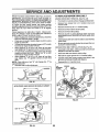
TO REMOVE MOWER
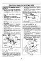
TO LEVEL MOWER HOUSING
(See Fig. 21)
.
Place attachment clutch in "DISENGAGED" position,
o
o
Turn height adjustment knob to lowest setting°
Lower mower to its lowest position,
o
Remove retainer spring holding anti-swaybar to chassis bracket and disengage anti-swaybar from bracket.
=
Remove retainer springs from suspension arms at
deck and disengage arms from deck.
Raise attachment lift to its highest position°
°
o
Remove two retainer springs from each front link and
remove links,
°
Slide mower forward and remove belt from electric
clutch pulley.
Adjust the mower whiletractor is parked on level ground or
driveway. Make sure tires are properly inflated (See
"PRODUCT SPECIFICATIONS" on page 3 of this manual).
If tires are over or underinflated, you will not properly adjust
your mower.
SIDE-TO-SIDE ADJUSTMENT (See Figs° 21 and 22)
° Raise mower to its highest position°
° Measure height from bottom of deck curl to ground
level at front comers of mower. Distance "A" on both
sides of mower should be the same,.
= If adjustment is necessary', make adjustment on one
side of mower only.
o To raise one side of mower, tighten lift link adjustment
nut on that side.
° To lower one side of mower, loosen lift link adjustment
nut on that side.
= Slide mower out from under right side of tractor,
IMPORTANT: IF AN ATTACHMENT OTHER THAN THE
MOWER DECK IS TO BE MOUNTED ON THE TRACTOR,
REMOVE THE FRONT LINKS.
TO INSTALL
NOTE: Each halfturn of adjustment nut wiFlchange mower
height about 3/16'L
Recheck measurements after adjusting,
MOWER
BOTTOM OF
BOTTOM OF
CURL
Follow procedure described in "INSTALL MOWER AND
DRIVE BELT" in the Assembly section of this manual.
ADJUSTMENT
NUTS
GROUND LINE
LIFT
LINKS
FRONT
SUSPENSION
FIG. 22
SUSPENSION
ARMS
BRACKET
CHASSIS
FRONT
SUSPENSION
BRACKET
LINKS
RETAINER
RETAINER
SPRING
ANTI-SWAY
BAR
FRONT MOWER
BRACKET
RETAINER
SPRINGS
FIG. 21
21
E AND ADJUSTM
,,llllll ,i ii
TO REPLACE
FRONT-TO-BACK ADJUSTMENT (See Figs° 23 and 24)
IMPORTANT; DECK MUST BE LEVEL SIDE-TO-SIDE,. IF
THE FOLLOWING FRONT-TO-BACK ADJUSTMENT IS
NECESSARY, BE SURE TO ADJUST B'OTHFRONT':C.INKS
EQUALLY SO MOWER WILL STAY LEVEL SIDE-TO-SIDE,
To obtain the best cutting results, the mower housing
should be adjusted so the front s app rox mately 1/8'_to1/2"
lower than the rear when the mower is in its highest
position..
Check adjustment on right side of tractor. Measure distance "F" directly in front of and behind the mandrel at
bottom edge of mower'housing as shown.
Before making any necessary adjustments,checkthat
:, both front links are equal in length.
•
If linksare not equal in length, adjust one linkto same
length as other fink_
•
•
T0 Iowerfront of mowerhousing, loosen nut"G" on both
front links an equal number of turns.
•
When distance "F" is 1/8" to t/2" _ower at front than
rear, tighten nut"H" against trunnion on both front links.
•
To raise front of mower housing, loosen nut "H" from
trunnion on both front links.. Tighten nut "G" on both
front links an equal number of turns,
•
When distance "F" is 1/8" to 1/2" lower at front than
rear, tighten nut "H" against trunnion on both front
links.
NOTE= Each full turn of nut "G" wilt change dim. "F" by
approximately 3/8",
•
Recheck side-to-side adjustrnenL
MOWER DRIVE BELT
MOWER DRIVE BELT REMOVAL (See Fig° 25)
Parktractor on a level surface. Engage parking brake_
Remove four screws from L.H. mandrel cover and
remove cover.
•
•
Rolt belt over the top of LHI, mandrel pulley.
Remove belt from electric clutch pulley.
•
Remove belt from idler pulleys.
•
Remove any dirt or grass clippings which may have
accumulated around mandrels and entire upper deck
surface_
•
Check primary idler arm and two idlersto see that they
rotate freely_
Be sure spring is securely hooked to primary idler arm
and bolt in mower' housing.
•
MOWER DRIVE BELT INSTALLATION (See Figo25)
•
Install belt in both idlers, Make sure belt is in both belt
keepers at the idlers as shown.
•
install new belt onto electric clutch pulley.
-
Roll belt into upper groove of LoHomandrel pulley.
•
Carefully check belt routing making sure belt is in the
grooves correctly and inside belt keepers.
Reassemble L,H. mandrel cover',
•
LH,
SCREWS
IDLER
PULLEYS
MANDREL
COVER_\_
ELECTRIC
CLUTCH
PULLEY
•
FIG. 23
MOWER
DRIVE
BELT
BOTH FRONT LINKS SHOULD BE EQUAL IN LENGTH
IDLER ARM
BELT
KEEPERS
FIG. 25
=_G=_
NUT "H
FRONT LINKS
FIG. 24
22
SERVICE AND ADJUSTMENTS
BLADE DRIVE BELT
=
Make sure attachment clutch and ignitionswitches are
in "OFF' position.
Park the tractor on level surface. Engage parking brake_
°
Remove mower ddve belt (See''TO REPLACE MOWER
DRIVE BELT" in this section of this manual)°
o
Adjust the three nylon locknuts until space between
clutch plate and rotor measures .012" at all three slot
locations cut in side of brake plate.
TO REPLACE
(See Fig. 26)
o
°
MOWER
•
Carefully roll belt off R.H, mandrel pulley.
°
Remove belt from center mandrel pulley, idler pulley,
and LH. mandrel pulley.
o
Remove any dirt or grass which may have accumulated around mandrels and entire upper deck surface.
°
Check secondary idler arm and idler to see that they
rotate freely°
.
o
=
Reconnect spring to bolt in mower housing and reinstall Roll. mandrel cover.
°
Reinstall mower to tractor (See "INSTALL MOWER
AND DRIVE BELT" in the Assembly section of this
manual).
Reassemble mower drive belt (See 'q_O REPLACE
MOWER DRIVE BELT" in this section of this manual).
L.H.
MANDREL
MOWER
BLADE
DRIVE BELT
CLUTCH PLATE
_
"
l_ t.........
\,
_
_
_--_
I_ '
...............
.012"
J
,',
1
_
NYLON LOCKNUT 131
Be sure spring is hooked in secondary idler arm and
sway-bar bracket.
Install new belt in lower groove of L,H_mandrel pulley,
idler pulley, and center mandrel pulley as shown°
Roll belt over Roll. mandrel pulley_ Make sure beit is in
all grooves properly.
_f
ROTOR k
SLOT (3)-_
.
=
NOTE= After installinga new electric clutch, run tractor at
full throttle and engage and disengage electric clutch 10
cycles to wear in clutch plate.
Remove mower (See "TO REMOVE MOWER" in this
section of this manual).
Remove four screws from R_H,, mandrel cover and
remove cover. Unhook spring from bolt on mower
housing.
\
BRAKE PLATE
FIG. 27
TO ADJUST
BRAKE
(See Fig. 28)
Your tractor is equipped with an adjustable brake system
which is mounted on the side of the transaxle_
If tractor requires more than six (6) feet stopping distance
at high speed in highest gear, then brake must be adjusted.
°
u
o
Depress clutch/brake pedal and engage parking brake.
Measure distance between brake operating arm and
nut 'W' on brake rod°
If distance is other than 1-1/2", loosen jam nut and turn
nut "A" until distance becomes 1-1/2", Retighten jam
nut against nut "A"o
Road test tractor for proper stopping distance as stated
above. Readjust if necessary. If stopping distance is
still greater than six (6) feet in highest gear, further
maintenance is necessary. Contact your nearest au thorized service centeridepartment_
CENTER
MANDREL
IDLER
PULLEY
R_H.
MANDREL
COVER
WITH PARKING BRAKE "ENGAGED"
,NUT "A"
NUT
SECONDARY
IDLER ARM
OPERATING
ARM
SPRING
SWAY-BAR
BRACKET
SCREW
FIG. 26
TO ADJUST ATTACHMENT
(See Fig. 27)
CLUTCH
_
The electric clutch should provide years of service. The
clutch has a built-in brake that stops the pulley within 5
seconds,, Eventually, the internal brake will wear which
may cause the mower blades to not engage, or, to not stop
as required. Adjustments should be made by your nearest
authorized service center/departmenL
FIG. 28
23
AND ADJUSTMENTS
TO REPLACE
(See Fig. 29)
MOTION
DRIVE BELT
TO ADJUST MOTION CONTROL
Fig. 30)
Park the tractor on level surface. Engage parkin_b_'ake_
For ease of service there is a belt Installation guide decal on
bottom of left footrest.
,
The motion controllever has been preset at the factory and
adjustment should not be necessary,
If for any reason the motion control lever will not hold its
positionwhileat a selected speed, it may be adjusted at the
friction pack located on the right side of chassis.
Remove mower (See "TO REMOVE MOWER '_in this
section of this manual.)
BELT REMOVAL •
Engage parking brake (creates slack in belt).,
•
°
Remove belt from clutching and fan idler pulleys°
Remove belt from transaxle pulley.
=
Remove belt from engine pulley and front V-idter
puitey.,
°
Pull belt out of alt belt keepers and remove fromtractor.
Place V part of beft into grooves on engine pulley and
front V-idler, making sure to route belt inside of all belt
keepers,
°
Route belt on left side, coming from engine pulley,
towards back of tractor and through loop in midspan
belt keeper..
o
Place V part of belt into grooves on transaxle and fan
idler pulleys, making sure to route belt inside of all belt
keepers.
°
Park tractor on level surface, Stop tractor by turning
ignition key to "OFF" position and engage parking
brake,
°
-
Place motion control lever in neutral (N) position.
While holding Iocknut, loosen jam nut
°
°
Tig!!ten !ocknut1/4 turn.
While holding tocknut, tighten jam nut securely.
Road test tractorafter adjustment and repeat procedure if
necessary.
Route belt on right side, coming from V-idler, towards
back of tractor, above midspan belt keeper and to top
of transaxle pulley.
°
•
NOTE: If for any reason the effort to move the motion
control lever becomes too excessive, reverse the above
adjustment procedure by loosening Iocknut 1/4 turn.
BELT INSTALLATION •
LEVER (See
TRANSMISSION
REMOVAUREPLACEMENT
Should your transmission require removal for service or
replacement, it should be purged after' reinstailation and
before operating the tractor. See "PURGE TRANSMISSION" in the Operation section of this manual.
.
_
i i lll
i llllllllll
LOCKNUrr
JAM
NUT
Place belt around clutching idlers as shown, making
sure to route belt inside of all belt keeper's.
CheCk to be sure belt is positioned correctly and is on
proper side of alt belt keepers.
°
Reinstall mower.
IMPORTANT: CHECK BRAKE ADJUSTMENT.
°
TRACTOR V-BELT DRIVE SCHEMATIC
VIEWED FROM L.H. SIDE OF TRACTOR
CLUTCHING
CLUTCHING
BELT
TRANSAXLE
FIG. 30
ENGINE
PULLEY
I
ABOVE BELT
V-IDLER
TO ADJUST
KEEPER
STEERING
WHEEL
ALIGNMENT
If steering wheel crossbars are not horizontal (left to right)
when wheels are positionedstraight forward, remove steer..
ingwheel and reassemble per instructionsin the Assembly
section of this manual.
BELT
"t3NISTS
BELT
KEEPER
FAN
IDLER
ASvIEWED FROM BOTTOM
FIG. 29
24
$ERVmCE AN
ADJU
ENTS
FRONT WHEEL TOE-IN ADJUSTMENT
Front wheel toe-in is required for propersteering Operation°
Toe-in was set at the factory and adjustment should not be
necessary If parts [n the front axle or steering mechanism
have been replaced or damaged, check toe-in and adjust
if necessary_
RETAINING
RING
AXLE
COVER
TO CHECK TOE-IN (See Fig° 31)
= Position front wheels straight ahead.
°
Measure distance between wheels at front and rear of
tires (dimensions 'W' and "B").
°
Front dimension "A" should be 1/8" to 1/4" less than
rear dimension "B".
FIG, 33
REAR WHEEL -
TO ADJUST TOE-IN (See Figs 3t and 32)
°
°
Loosen jam nuts at adjustment sleeves on tie rod°
Adjusttle rod until dimension "A" is 1/8" to 1/4" _essthan
dimension "B"_
°
Tighten jam nuts securely.
°
o
Block rear axle securely.
Remove five (5) hub bolts to allow wheel removal.
=
Repair tire and reassemble° Replace and tighten hub
bolts securelyo
TO START ENGINE WITH A WEAK BATTERY
(See Fig. 34)
I
Hill
iii
CAUTION: Lead-acid batteries generate explosive gases. Keep sparks, flame
and smoking materials away from batteries. Always wear eye protection
when around batteries.
If your battery is too weak to start the engine, it should be
recharged,
If "jumper cables" are used for emergency
starting; foIlow this procedure:
FIG. 31
IMPORTANT: YOUR TRACTOR IS EQUIPPED WITH A 12
VOLT NEGATIVE GROUNDED
SYSTEM.
THE OTHER
VEHICLE
MUST ALSO BE A 12 VOLT NEGATIVE
GROUNDED SYSTEM.
DO NOT USE YOUR TRACTOR
BATTERY TO START OTHER VEHICLES
ADJUSTMENT
ISLEEVES
TO ATTACH JUMPER CABLES °
Connect each end of the RED cable to the POSITIVE
(+) terminal of each battery', taking care not to short
against chassis.
° Connect one end of the BLACK cable to the NEGATIVE (-) terminal of fully charged battery°
° Connect the other end of the BLACK cable to good
CHASSIS GROUND, away from fuel tank and battery.
JAM
/
TIE ROD
FIG. 32
TO REMOVE CABLES, REVERSE ORDER = BLACK cable first from chassis and then from the fully
charged battery.
RED cable last from both batteries.
FRONT WHEEL CAMBER
The front wheel camber is not adjustable on your tractor° If
damage has occurred to affect the front wheel camber,
contact your nearest authorized service center/department.
TO REMOVE
WHEEL FOR REPAIRS
FRONT WHEEL (See Fig° 33)
Block up axle securely.
•
Remove axle cover, retaining ring and washers to atlow
wheel removal.
•
•
°
"POSITIVE"
(+)
"NEGATIVE"
Repair tire and reassemble°
Replace washers and snap retaining ring securely in
axle groove.
Replace axle cover
25
FIG. 34
(-)
S
AND ADJUSTMENTS
III
TO REPLACE
8
O
HEADLIGHT
III
IIIIiiiiiiiii
II
I
III
IIIIIIIIIIIII
BULB
IIII
ADJUSTMENT
Raise hood_
II
III
IIIII
II
i
I
SPRING BUSHING
Pull bulb holder out of the hole in the backside_of the
grill,,
Replace bulb in holder and push bulb holder securely
back into the hote in the backside of the grill _:
Close hood,
INTERLOCKS
AND RELAYS
Loose or damaged wiring may cause your tractor to run
poorly, stop running, or prevent it from starting.
•
Check wiring. See electrical wiring diagram in the
Repair Parts section of this manual.
TO REPLACE
FIG. 35
TO REMOVE
FUSE
Replace with 30 amp automotive-type plug-in fuse° The
fuse holder is located behind the dash.
TO ADJUST ATTACHMENT
ATTACHMENT
LIFT SPRING
JAM NUT
LIFT SPRING
•
Unsnap headlight wire connector;
•
Stand in front of tractor. Grasp hood at sides, tilt toward
engine and lift off of tractor.
•
To replace, reverse above procedures.
(See Fig. 35)
•
While holding spring bushing with wrench, loosen jam
nut°
•
Turn adjustment bolt clockwise to extend spring and
reduce lift effort for heavier attachments_
°
Turn adjustment bolt counterclockwise for lighter attachmentso
HOOD AND GRILL ASSEMBLY
(See Fig. 36)
I
Raise hood.
HEADLIGHT
WIRE
CONNECTOR
HOOD
•
RetJghten jam nut against spring bushing.
IMPORTANT:
DO NOT ADJUST FOR MAXIMUM SPRING
TENSION WHEN USING LIGHT ATTACHMENTS
SUCH
AS A MOWER. ADJUST LiFT LEVER SPRING TO AID IN
LIFTING ATTACHMENT.
DO NOT OVERPOWER SPRING.
WHEN REMOVING
ATTACHMENT,
ALWAYS ADJUST
SPRING TENSION TO ITS LOWEST POSITION_
FIG. 36
SERVmCEA
AD, USTMENTS
ENGINE
ACCELERATION
TO ADJUST THROI-rLE
(See Figs. 37 & 38)
CONTROL
°
GABLE
The throttle control has been preset at the factory and
adjustment should notbe necessary. Checkadjustment as
described below before loosening cable. If adjustment is
necessary, proceed as follows:
°
With engine not running, move throttle controllever to
fast (,_) position.
°
Check that speed controllever is against stop screw. If
it is not, loosen casing clamp screw and pui! throttle
cable untillever is against screw. Tightenclamp screw
securely.
TO ADJUST
CARBURETOR
TEST -
Move throttte control lever from slow (,e_) to fast (,_)
position. If engine hesitates or dies, turn idle mixture
screw out (counterclockwise)
1/8 turn° Repeat test and
continue to adjust, if necessary, until engine accelerates smoothly.
High speed stop is factory adjuste& Do not adjust-damage
may result.
IMPORTANT;
NEVER TAMPER WITH THE ENGINE
GOVERNOR, WHICH tS FACTORY SET FOR PROPER
ENGINE SPEED.. OVERSPEED_NGTHE
ENGINE ABOVE
THE FACTORY
HIGH SPEED
SETTING
CAN BE
DANGEROUS.. IF YOU THINK THE ENGINE-GOVERNED
HIGH SPEED NEEDS ADJUSTING,
CONTACT
YOUR
NEAREST
AUTHORIZED
SERVICE
CENTER/
DEPARTMENT, WHICH HAS PROPER EQUIPMENT AND
EXPERIENCE
TO
MAKE
ANY
NECESSARY
ADJUSTMENTS.
(See Fig, 39)
The carburetor has been preset at the factory and adjustment should not be necessary, However, minor adjustment
may be required to compensate for differences in fuel,
temperature, altitude or load,,If the carburetor does need
adjustment, proceed as follows:
CASING
CLAMP.
SCREW \
In genera!, turning the adjusting needles in (clockwise)
decreases the supply of fuel to the engine givinga leaner
fuel/air mixture° Turning the adjusting needles out (coun.,
terclockwise) increases the supply of fuel to the engine
giving a richer fue!!air mixture,,
IMPORTANT: DAMAGE TO THE NEEDLES AND THE
SEATS IN CARBURETOR MAY RESULT IF SCREW IS
TURNED IN TOO TIGt4T,,
STOP SCREW
SPEED CONTROL
LEVER
THROTTLE
CONTROL
CABLE
PRELIMINARY SETTING •
Be sure you have a clean air filter, and the throttle
control cable is adjusted properly (see above)°
o
With engine off turn idlefuel adjusting needle in (clockwise) closing it finger tight and then turn out (counterclockwise) 1-'1/4 turns.
•
Turn main fuel adjusting needle in (clockwise) closing
finger rig ht and then turn out (counterclockwise) 1 turn.
' FIG. 37
STOP
SPEED
CONTROL
LEVER
FINAL SETTING •
Start engine and allow to warm for five minutes. Make
final adjustments with engine running and shift/motion
control lever in neutral (N) position.
•
Withthrottle control leverin fast (,_) position, turn main
fuel adjusting needle in (clockwise) until engine begins
to die then turn out (counterclockwise) until engine
runs rough. Turn needle to a point midway between
those two positions.
°
FIG. 38
Idle speed setting - With throttle control lever in slow
(,_)
position, engine should idle at 1400 RPMo If
engine idles too stow or fast, turn idle speed adjusting
screw in or out until correct idle is attained.
,,
idle fuel needle settinq - With throttle control lever in
slow (,_) position, turn idle fuel adjusting needle in
(clockwise) until engine begins to die and then turn out
(counterclockwise) until engine runs rough. Turn needle
to a point midway between those two positions.
o
Recheck idle speed. Readjust if necessary.
IDLE FUEL
IDLE SPEED
ADJUSTING
SCREW
NEEDLE
MAIN FUEL
ADJUSTING
NEEDLE
27
FIG. 39
STORAGE
ENGINE
Immediately prepare your'tractor for storage at the,;,endof
the season or if the tractor will not be used for 30 days or
more.
FUEL SYSTEM
llLu
IMPORTANT: IT IS iMPORTANT TO PREVENT GUM
DEPOSITS FROM FORMING IN ESSENTIAL FUEL
SYSTEM PARTS SUCH AS CARBURETOR, FUEL FILTER,
FUEL H_)SE, OR TANK DURING STORAGE. ALSO,
EXPERIENCE INDICATES THAT ALCOHOL BLENDED
FUELS (CALLED GASOHOL OR USING ETHANOL OR
METHANOL} CAN ATTRACT MOISTURE WHICH LEADS
TO SEPARATION AND FORMATION OF ACIDS DURING
STORAGE. ACiDiC GAS CAN DAMAGE THE FUEL
SYSTEM OF AN ENGINE WHILE IN STORAGE.
•
Drain the fuel tank,
CAUTION: Never store the tractor with
where
fumes
may
reach
an open
flame
gasoline
in the
tank
inside
a building
or spark. Allow the engine to cool
before storing in any enclosure,
.....................
II1'1III
TRACTOR
Remove mower from tractor for winter storage. When
mower is to be stored for a period of time, clean it thoroughly, remove all dirt, grease, leaves, etc. Store in a
clean, dr,' area.
° Clean entire tractor (see"CLEAN1NG" in the Customer
Responsibilities section of this manual).
°
Inspect and replace belts, if necessary (See belt replacement instructions in the Service and Adjustments
section of this manual).
•
Lubricate as shown in the Customer Responsibilities
section of this manual,
°
Be sure that all nuts, bolts and screws are securely
fastened, inspect moving parts for damage, breakage
and wear. Replace if necessary.
•
Touch up all rusted or' chipped paint surfaces; sand
lightly before painting.
Fully charge the battery for storage.,
•
After a period of time in storage, battery may require
recharging.
To help prevent corrosion and power leakage during
long periods of storage, battery cables should be
disconnected and battery cleaned thoroughly (see'frO
CLEAN BATTERY AND TERMINALS in the Customer Responsibilities section of this manual).
After cleaning, leave cables disconnected and place
cables where they cannot come in contact with battery
terminals.
°
•
•
•
Start the eng!ne and let it run until the fuel lines and
cai;buretor are empty_
°
Never use engine or carburetor cleaner products in the
fuel tank or permanent damage may occur.
Use fresh fuel next season.°
,
NOTE: Fuel stabilizer is an acceptable alternative in
minimizing the formation of fuel gum deposits during storage. Add stabilizer to gasoline in fuel tank or storage
container, Always follow the mix ratio found on stabilizer
container. Run engine at least 10 minutes after adding
stabilizer to allow the stabilizer to reach the carburetor. Do
not drain the gas tank and carburetor if using fuel stabilizer_
ENGINE OIL
Drain oil (with engine warm) and replace with clean engine
oil. (See =ENGINE" in the Customer Responsibilities
section of this manual),
BATTERY
°
°
CYLINDERS
•
•
°
=
Remove spark plug(s),
Pour one ounce of oil through spark plug hole(s) into
cylinder(s)o
Tumignitionkeyto"START"positionforafewseconds
to distributeoil,
Replace with new spark plug(s),
OTHER
Be sure battery drain tube is securely attached.
°
Do not store gasoline from one season to another,
if battery is removed from tractor for storage, do not
store battery directly on concrete or damp surfaces.
°
Replace your gasoline can if your can starts to rust.
Rust and/or dirt in your gasoline will cause problems,.
°
If possible, store your tractor indoors and cover it to
give protectionfrom dust and dirt°
°
Cover your tractorwith a suitable protective coyer'that
does not retain moisture_ Do not use plastic. Plastic
cannotbreathe whicha;llowscondensation toform and
will cause your tractor to rust,
IMPORTANT: NEVER COVER TRACTOR WHILE ENGINE
AND EXHAUST AREAS ARE STILL WARM°
28
T
UBLESHOOTING
-
,,,i,l,,,ll,i ii,i ii
PROBLEM
Will not start
lll l
POnNTS
ii
................................
CAUSE
CORRECTION
1.
2.
3.
4.
5.
6_
7.
Io
Out of fuel.
2..
3.
4.
5.
6.
7..
Engine not "CHOKED" propedy
Engine flooded.,
Bad spark plug_
Dtrbj air filter..
Dirty fuel filter.
Water In fuel.
8_
9.,
10..
Loose or damaged wtdngr
Carburetor out of adiustrnent
Engine valves out of adjustment.
Fill fuet tank.
See "TO START ENGINE" ]n Operation section.
Waft several minutes before attempting to start
Replace spark plug.
Clear#replace air filler
Replace fuel filter_
Drain fuel tank and carburetor, refill tank with fresh
gasoline and replace fuel filter.
8. Check all wiring
9. Contact an authodzed service center/department.
10., Contact an authorized servtce centerfdepartment..
Hard to start
1. Dirty air filter.
2. Bad spark plugo
3.. Weak or dead battery.
4o Dirty fuel filter.
5. Stale or dirty fuel
6. Loose or damaged widng.
7. Carburetor out of adtusb'nent.
8. Engine valves out of adjustment
1..
2.
3.
4.
5.
6.,
7r
B.
Clean/replace air filler
Replace spark plug.
Recharge or replace battery.
Replace fuel fitter.
Drain fuel tank and refll with fresh gasollne_
Check all wtdng.,
Contact an authorized service center!department.
Contact an authodzed service center/depertmenL
Engine Will not turn over
1..
2.
3.
4_
5.
6.
7..
8.
9.
C{utchibrake pedal not depressed.
Attachment c{utch fs engaged.
Weak or dead battery.
Blown fuse.
Corroded battery terminals.
Loose or damaged widng
Faulty ignition switch.
Faulty solenoid or starter.
Faulty operator presence switch(as).
1.
2.
3,
4.
5.
6.
7.
8.
9.
Depress clutch/brake pedal.
Disengage attachment clutch.
Recharge or replace battery..
Replace fuse.
C{ean battery terminals.
Check all widng..
Check/replace Ignition switch
Check/replace solenoid or starter_.
Contact an authorized service center/departmenl.
Engine clicks but will not
start
1.
2.
3.
4.
Weak or dead battery_
Corroded battery terminals.
Loose or damagedwldng.
Faulty solenoid or starter.
t.
2,
3.
4..
Recharge or replace battery_
Clean battery terminals
Check atl widng..
Check/replace solenoid or starter..
Loss of power
!4
1.
2_
3.
4o
5
6.
7.
8.
9.
Set in "Higher Cut" poslfer#reduce speed.,
Adjust throtlla control.
Clean underside of mower housing.
Clear#replace air ll{ter_
Check oil level/change oil.
Clean and regap or change spark plug_
Replace fuel filter
Drain fuel tank and refill with fresh gasoline.
Drain fuel tank and carburetor, refll tank with fresh
gasoline and replace fuel filter.
Connect and fighlen spark plug wire
Clean engine air screer#fins.
Clean/replace muffler.
Cheek all widng
Contact an authorized service centerldepartment_
Contact an authorized service tenter!department.
i
i
Cutting too much grass/too fast.
2. Throtl!e In "CHOKE" position.
3
Build-up of grass, leaves and trash under mower..
4. Dirty air filter.
54 Low ott leveVdirty oil
6. Faulty spark plug.
7_ Dirty fuel filler.
8o Stale or dirty fue!.
9_ Water in fuel.
_0.
!1.
!2_
13.
t4_
15..
i
Excessive vibration
III
i
Spark plug wire loose..
Dirty engine air screenJtins.
Dirtylclogged muffler
Loose or damaged wtdng.
Carburetor out of adjustmenL
Englne valves out of adjustment.
i
i
10
11.
!2..
13,
14.
15.
L
1.
2.
Wom,:berj.t or loose blade.
Bent blad'_'_mandrel.
3.
Loose/damaged
1.. Replace blade° Tighten blade boil
2. Replace blade mandrel.
3. Tighten loose part(s)o Replace damaged pads.
pad(s).
29
IIIIIIIHII
i::................................
ill
i,illll,
,JlJl,Jl,,i,,,i,,ll
iillll
ii
ii i
ill
i/
TROU
Engine continues to run
when operator leaves seat
with attachment clutch
.
.........
POINTS
CAUSE
PROBLEM
................
CORRECTION
1_
Faulty operator-safety !orese'_ce control system,
1.
Check wiring, switches and con_ectionso If not
corrected, contact an authorized _ervtce center/
department
1.
2.
3
4.
Wom, bent or loose blade.
Mower deck not level.
Buildup of grass, leaves, and trash under mower,
Bent blade mandrel,
5,.
Clogged mower deck vent holes from buildup of
grass, leaves, and trash around mandrels,
1,
2
3,
4.
5
Replace blade,, Tighten blade bolt.
Level mower deck.
Clean underside of mower housing.
Replace blade mandrel,
Clean around mandrels to open vent holes,
engaged
Poor cut _ uneven
........
, , ,
Mower blades will not
rotate
Poor grass discharge
,,,
1.
Obstruction in c_utchmechanism,
!.
Remove obstructio'_
2
3.
4.
WOrn!damaged mower drive belt.,
Frozen Idler putiey.
Frozen blade mandrel.
2,
3
4,
Replace mower drive belt
Repface idler pulley.
Replace blade mandrel.
1.
2,
3.
4.
Engine speed too slow.
Travel speed toofast,,
Wet grass,
Mower deck not level,
5,
6.
7,,
8.
9,
10
11.
Lowluneven tire air pressure,.
Worn, bent or loose blade.
Buildup of grass, leaves and trash under mower
Mower drive belt worm
Blades Improperly Installed.,
Improper bfades used,,
Clogged mower deck vent holes from buildup of
grass, leaves, and trash around mandrels,
1,
2,
3,.
4.
5
6
7
8,
9,
10
11.
Place throttle control in "FAST" position.
Shift to slower speed.
Allow grass to dry before mowing,
Level mower deck,
Check tires for proper air pressure.
Replacefsharpen blade. Tighten blade bolt,
Clean underside of mower housing,.
Replace mower ddv_ belt,
Reinstall blades sharp edge down
Replace with blades listed tn this manual.
Clean around mandrels to open vent holes.
Headlight(s) not working
(if so equipped)
I.
2_
3_
4.
5,
Swltch ts"OFP_
Bulb(s) bumed out
Faulty light switch,
Loose or damaged wldng
Blown fuse.,
1,
Turn switch "ON",
2,
3,,
4.
5,
Replace bulb(s).
Check/replace light switch
Check wiring and connections,
Replace fuse.
Battery will not charge
t.
2.
Bad battery celt(s).
Poor cable connect!ons
3_
4
Faulty regulator (if so equipped)
Faulty altemator,_
1.
2,
3,
4,.
Replace battery.
Check/clean all connec_ons,
Replace regulator.
Replace alternator.
Loss of drive
t.
2.
3.
Freewheel control in "disengaged" position.
Motion drive belt worn, damaged or broken.
Air trapped in transmission during shpment
or servicing,,
1.
2,,
3,
Place freewheel control tn "engaged" position.
Replace motion ddve belt.
Purge transmission,,
Engine "backfires"
when turning engine
"OFF"
1.
Engine throttle control not set at "SLOW"
position for 30 seconds before stopping engtne.
30
Move throttle control to "SLOW" position and allow
to idle for 30 s_conds before stopping engtne_
TRACTOR
- - MODEL
NUMBER
917.251492
SCHEMATIC
RED
BLACK
BATTERY
FUSE 30 AMP°
RED
U",.D
AMMETER
WHITE
S
WHrt_
BLACK
J
IGNITION
SWITCH
SEAT SWITCH
(NOT OCCUPIED)
1 ....
,_/
4 ....
2 J_Z_
1
_
1
_
l
l
f._ i
_ '.
BLACK
t3
o-111 '--_6
-_
_ _ LL
1{DISENGAGED)
GROUNDING CONNECTOR
@
BLACK
UNIT
IGNITION
CHARGING
PLUGS
SPARK
_
SYSTEM OUTPUT
_ AMP
pce 3600
nPM
(_
REGULATOR
I
YELLOW
28 VOLTS AO '8 3600 RPM
(REGULATOR
DISOONNEOTED)
RED
ORANGE
I ......
1
HEADL'(_I_T
__
SWITCH (OFF)
HEADLIGHTS
M
/-
7
rT---T1
---O-REMOVABLE
O
NON-REMOVABLE
CONNECTIONS
IGNITION
SWITCH
POSITION
CIRCUIT
OFF
ON
START
M+G
B+L
B+S+L
CONNECTIONS
WIRING INSULATED CLIPS .
NOTE: IF WIRING INSULATED
CLIPS WERE REMOVED FOR
SERVICING OF UNIT, THEY
SHOULD BE REPLACED TO
PROPERLY SECURE YOUR WIRING
31
GFC
_Bn
E _nB
D _nA
PTO SWITCH
OFF
POStTION
ON
}
_
CIRCUIT
C+F,B+E,A+DJ
I1
REPAIR PARTS
TRACTOR
-- MODEL
NUMBER
917.251492
ELECTRICAL
22
t
l
I
I
I
I
I
I
I
i
2O
"i
I
/
//
//
/
/
/
11
1
1
32
REPAltR PARTS
TRACTOR -- MODEL NUMBER 917.251492
ELECTRICAL
KEY
NO.
PART
NO/'
1
2
3
4
6
7
8
9
10
11
12
19
20
21
22
24
25
26
28
29
30
31
32
33
34
39
40
41
42
43
45
49
50
51
53
54
146140
74760412
STD551125
STD551025
STD541025
7697J
7603J
109596X
145211
145209
145769
STD551125
73350400
136850
4152J
4799J
146149
108824X
4207J
121305X
144921
140400
141226
140403
1107t2X
109553X
146065
17720408
131563
145673
122822X
153249
146283
140405
71031008
73951000
DESCRIPTION
Battery
Bolt Hex Head 1/4-20 x 3/4
Washer, Lock 1/4
Washer 9/32 x 5/8 x 16 Ga
Nut Fin Hex 1/4-20
Tube Plastic
Tray, Battery
Clamp, Hose
Bolt Wet BTR 1/4-20 x 7.5 Zinc
Hold down Battery Dash Mount
Nut Push Nylon 1/4" Wet Battery
Washer, Lock 1/4
Nut, Jam Hex 114-20
Harness Socket Light Wi4152J
Bulb Light
Cable, Battery
Cable 6 Gao Red 12o5"W 16 Wire
Fuse
Cable, Ground
Switch, Plunger
Switch, lgn
Nut, IgnitionSwitch
Cover Switch Key
Key
Switch, Light
Intlk Switch
Harness Ign.
Screw 1/4-20 x 1/2
Cover, Terminal Red
Solenoid
Ammeter
Washer Pinned Delta
Switch, PTO
Ring Retainer PTO
Screw Hex Washer Hd #t0-32 x 1
Nut Keps #10-32
NOTE: All component dimensions given in UoSoinches
1 inch = 25A mm
33
REPAIR PARTS
TRACTOR
CHASSIS
- - MODEL
NUMBER
917.251492
AND ENCLOSURES
18
38
59
2
102
7
101
86
34
15
REPAUR PARTS
TRACTOR - - MODEL NUMBER 917,251492
CHASSIS AND ENCLOSURES
KEY
NO.
PART
NO.
1
2
3
4
5
6
7
8
9
10
11
'12
13
14
15
16
17
18
19
20
21
22
24
26
28
29
30
31
32
33
34
35
36
37
38
39
40
41
42
150253
140506
136671X558
73800700
145203
150273
17720408
145166
108067X
19092016
137270
t37269
137271
136673X558
136374
121794X
17490612
136373X428
19131312
74760616
73680600
136670X558
145243X558
17490512
145244X558
145349
145052
t45183
!41315
141314
142131
19111116
74780512
140002X558
19091216
!36961
142132
17580408
72140608
DESCRIPTION
Rail, Frame RH
Drawbar, Gt
Panel Asm., Side LH
Nut, Lock Hex 7/16 Unc
Dash, Plastic Black
DashAsm., Lower
Screw, Thd Cut 1/4-20 x 1/2
Support, Battery
Nut, Pal
Washer 9/32x 1-t/4x t6 Ga.
Rivet, Ratchet Male
Washer, Nylon
Rivet, Ratchet Female
Hood Asm., Pnt
Lens, BarClear
Cover, Access
Screw, Thdrol 3/8-16 x 3/4
Gdlle
Washer 13/32 x t3/16x 12 Ga.
Bolt, Fin Hex 3/8-16 x 1
Nut, Crowntock 3/8-16 Unc
Panel Asm., Side RH
Footrest, RH
Screw, Thdrol 5/16-18x3/4
Footrest, LH
Bracket, Support Dash
Saddle, Hydro 1995
Brace, Support Steering
Bracket Asmo, Frame Pivot Lh
Bracket Asm., Frame Pivot Rh
Bracket, Engine Support Rear
Washer 11/32x11/16x16Gao
Bolt, Fin Hex 5/16-18 x 3/4
Fender, Pnt.
Washer 9i32x3/4x16Ga.
Bracket, Axle Front
Bracket, Support AxlelEngine
Screw Tap Tile 1/4-20 x 1/2
Bolt, Carnage 3/8-16 x I
KEY
NO.
PART
NO.
43
44
45
47
48
49
50'
52
53
56
57
58
59
60
63
64
68
69
70
77
84
86
90
9t
92
94
95
98
99
100
10I
102
103
106
120
---
136939
136940
138460
17490608
136814
.136813
152728
73680500
137304
138461
73640400
137t13
74180412
17490620
19131614
144283
17490508
153991
137159
137308
142992
74760716
t1050600
150851
143485X013
100207K
105531X
140503
140871
124236X
17490628
4497H
142273
138776
19131616
8022J
DESCRIPTION
Bracket, Spnsn Front Lh
Bracket, Spnsn Front Rh
Bracket Asm., Susp Chassis Rh
Screw Thdrol 3/8-16 x 1/2
Bracket Asm., Pivot Hood Lh
Bracket Asm., Pivot Hood Rh
Bracket, Chassis Front
Nut, Crown!ock 5/16-18
Rod, Support Hood
Bracket Asm., Susp Chassis Lh
Nut, Keps Hex 1/4-20
Bracket Asm., Fender
Screw, Mach Cr 1/4-20 x 3/4
Screw Thdrol 3/8-16 x 1-1/4
Washer 13/32 x I x t4 Ga..
Washer, Serrated Disc 13/32 x t
Screw, Thd 5/16-I8 x 1/2
Shield, Heat
Guide, Belt Mid Span
Shield, Front
Stop, Over Center Mower
Bolt, Fin Hex 7/16-14 Unc x 1
Washer, Lock External Tooth 3t8
Rail, Frame Lh
Plate, Silkscreen Dash
Clip, Fuel Line
Push Nut, Nylon
Bracket SkidChassis
Rod By Pass
Cap By Pass Rod
Screw Thdrol 3/8-16 x 1-3/4
Retainer, Spring
Lock, By Pass
Bolt 5116-18 Type TT
Washer 13/32 x I x 16 Ga.
Plug, Hole
NOTE: All componer_t dimensions given in U.So inches
1 inch = 25°4 mm
35
TRACTOR
" " MODEL NUMBER 917,251492
46
64
37
38
8O
49
47
87
\
72
109
|
/
I
g9
75
/
10_
I
97
,101
100
107
72
103
36
REPAUR PARTS
TRACTOR
GROUND
KEY
NO.
2
3
5
6
7
9
15
17
20
22
23
28
29
30
32
33
34
35
36
37
38
39
40
41
42
43
44
45
46
47
48
49
50
51
52
53
54
55
56
58
6!
64
65
66
67
- - MODEL
NUMBER
917.251492
DRIVE
PART
NO.
7070E
7563R
STD541437
STD5612!0
140507
140080
STD551037
140921
73940800
140498
106933X
STD541237
140494
19131616
73220700
12000053
124236X
137648
149412
121749X
150035
74321016
5304J
73631000
8883R
74760412
104601X
73800400
14517O
138228
72110614
19131413
131494
STD541437
139123
207J
138390
105706X
140218
74760724
140488
154752
67609
140296
19131312
KEY
NO.
DESCRIPTION
Key 1/4 x 2.5
Washer Thrust Axle Harden
Nut Crownlock 3/8-16
Pin Cotter 1/8 x 3/4
Wheel Hub Asm.
Bolt Hub
Washer 13/32 x t3/16 x 16 Ga
Spring Rod Brake
Nut Hex Jam Toplock 1/2-20
Shaft Arm Asm
Knob
Nut
Brake Rod
Washer 13/32 x 1 x 16 G&
Nut Hex 7/16-14
Ring E
Cap Plunger
Rod Parking Brake
Spring, Drive Ground
Washer 25/32 x 1-1/4 x 16 Gauge
Nyliner
Screw Fin #10-24 x t
Actuator Interlock Switch
Nut Lock #10-24
Cover Pedal
Bolt Hex Head 1/4-20 x 3/4
Bracket interlock
Nut Lock W/Insert 1/4-20
Retainer Spring
Clutch Rod
Bolt Carriage 3/8-16 x 1-3/4 Gr 5
Washer 13/32 x 7/8 x 13 Ga
Pulley Idler Flat
Nut Crownlock 3/8-16 UNC
Pulley Idler Grooved
Washer Hartdened
Clutch Arm Asm
Bearing, Idler
V-Belt
Bolt Fin Hex 7116-14 x !-1/2
Puller.v"Transaxle
Shaft Asm Brake Parking Clutch
Bolt Shoulder
Washer Hardened
Washer 13/32 x 13/16 x 12 Ga
68
69
70
71
72
73
74
75
.. 76
77
78
79
80
81
82
83
84
85
86
87
88
89
90
91
92
93
94
95
96
97
98
99
t00
t01
102
103
104
105
106
107
108
109
110
--
PART
NO.
5I42H
123800X
151146
151179
STD54t431
74780548
142432
73800700
140481
74760716
19111212
72110505
140484
17490612
150586
140479
140490
17541020
140462
140491
140492
73680700
140489
17490644
74760520
140502
133835
23200528
141103
126874X
141004
17490624
126881X
59285
73560500
73350500
140480
17580408
142918
154739
142917
140929
88652
150073
DESCRIPTION
Pin Roll
Washer
Console Hydro Fender
Plate Console Shift
Locknut Hex WfWasher insert
Bolt Fin Hex 5/16-18 x 3
Screw Hex Wsh. Hi-Lo 1/4-1/2
Nut Lock Hex 7/16
Bracket Transaxle
Bolt Fin Hex 7/16-14 x 1
Washer 11/32 x 3/4 x 12 G a
Bolt Carriage 5/16-t8 x 5/8
Bracket Torque RH
Screw Thdrol 3/8-16 x 3/4
Bracket Mount Torque/Fan
Strap Torque Mid
Spacer
Screw#10_24x 1-1/4
Fan 7" Hydro
Adapter Fan
Pulley Idler
Nut Crownlock 7/'16-14 UNC
Keeper Belt
Screw Thdrol 3/8-I6 x 2-3/4
Bolt Fin Hex 5/16-18 x 1o25
Link Shift Asm
Fastner Christmas Tree
Screw Set 5/16_18 x 1o5
Washer Nickel Plated
Bearing Trust
Bracket Shift
Screw Thdrol 3/8-16 x 1-1/2
Washer Compression
Washer Bellville
Nut Hex Nylok
Nut Hex Jam 5/16-18
Bracket Idler
Screw Tap 1/4-20 x 1/2
O-Ring Asm Hydro Gear 70110
Line Fuel Hydro 15" VGT Sew.
Cap Asm Vent Hydro Gear 70109
Spring Return Brake
Bolt
Transaxle Hydro
NOTE: All component dimensions given in U°S. inches
1 inch = 2&4 mm
37
REPAIR PARTS
TRACTOR
STEERING
- - MODEL
ASSEMBLY
21
20
34
33
32
6
27
t9
38
NUMBER
917.251492
REPAIR PARTS
TRACTOR
STEERING
- - MODEL
NUMBER
917,251492
ASSEMBLY
KEY
NO.
PART
NO°
1
2
3
4
5
6
7
8
9
t0
11
12
13
14
15
16
17
121472X
137094
6855M
13696,0
136959
6266H
121748X
12000029
121232X
74781044
136518
73901000
124749X
STD551t37
STD54t537
145103
137347
18
19
2O
21
22
23
24
25
26
27
28
29
30
31
32
33
34
35
36
37
38
39
4O
137155
146611
145182
100711L
t554J
152927
19133808
747806"t6
126805X
3366R
17490612
104239X
12000034
138136
1911161O
STD551131
74760512
138059
137156
73360600
109850X
73700600
109851X
DESCRIPTION
Wheel, Steering
Axle Asm. Front
Fitting, Grease
Spindle Asm, LH
Spindle Asrno, RH
Bearing, Race Thrust Harden
Washer 25/32 x 1-5/8 x 16 Ga.
Ring, Kiip #T5304-75
Cap, Spindle
Bolt, Fin Hex 5/8-! 1 x 2-3t4
Spacer, Brg. Axle Front
Nut, Lock Flange 5/8-11 Unc
Washer 25/32 x 1-1/4 x 16 Ga.
Washer, Lock Hvy Hicl Spr 3/8
Nut, Lock Center 3/8-24 Unf
Shaft Asm., Steering
Rod Asm., Tie Ball J Bali Vgt (Inc.
Key No. 36-40)
Draglink, Ball ,Joint Solid Vgt
Support Asm,, Steering Vgt
Column, Steering
Adapter, Wheel Steering
Bushing, Strgo Blk
Screw
Washer 13/32 x 2o3/8 x 8 Ga.
Bolt, Fin Hex 3/8-16 x 1 Gr. 5
Cap, Wheel Steering
Bearing, CoL Strg.
Screw, Thrdrol 3/8-16 x 3/4
Bearing, Flange
Ring, Klip Truarc #5304-75
Bushing, Nyliner Snap
Washer 11/32x i x 10Ga.
Washer, Lock Hvy HIcl Spr 5/I6
Bolt, Hex Hd 5/16-18 x 3/4
Gear, Sector Steering
Tie Rod
Jam Nut RH Thread
Joint Asm. Bali RH Thread
Jam Nut LH Thread
Joint Asm,. Ball LH Thread
NOTE: All component dimensions given in U.S. inches
1 inch = 25.4 mm
39
REPAIR PARTS
TRACTOR
- - MODEL
NUMB ER 917.251492
ENGINE
1
\
3O
62
34
32
39
24
39
13
12
14
11
18
15
17
41
42
37
43
/5
28
29
/
37
16
I SPARK ARRESTER KIT ]
4O
REPAIR PARTS
TRACTOR -- MODEL NUMBER 917.251492
ENGINE
KEY
NO.
PART
NO.
1
14t948
2
144110
3
4
5
6
8
9
10
11
12
13
14
15
16
17
18
19
13240300
13280328
13200300
138129
121361X
150828
105432X
137140
136907
154575
154574
151346
t09227X
106082X
151296
132903O0
20
2t
22
23
24
25
26
27
28
29
30
32
34
35
36
37
39
40
41
42
43
45
62
133439
17720410
138672
191326'16
STD551237
73920600
3645J
139277
7834R
132920
105037X
1749O5O8
17720408
STD551131
74570512
I23487X
17490624
17490652
126197X
STD551143
15028O
128861
137373
DESCRIPTION
Engine Koh{er
Model MV18S-58560
Muffler Asm Kohler VGT
(Inc, Key No. 34)
Etbow Street 3/8 NPT
Nipple Pipe 3/8NPT X 3 - 1/2
Elbow STD 90 Degree 3/8 - 18 NPT
Clamp Tube Double Engine
Pulley V-idler '
Keeper Asm Belt Engine
Bushing
Clutch Electric
Pulley Engine VGT Elect Clutch
Baffle Air LH Koh VGT
Baffle Air RH Koh VGT
Tank Fuel Rear 3°50 YT/GT
Pad Spacer
Pad Spacer
Cap Asm Fuel W/Gauge Vented
Ptug Oil Drain
Order From Engine Manufacturer)
ontrol Throttle
Screw Hex Thd Cut 1/4 - 20 X 5/8
Control Choke
Washer 13/32 X 1 - 5/8 X 16 Ga
Lock"washer Ext Tooth 3/8
Nut Keps 3/8 - 24 UNF
Bushing
Stem Tank Fuel
Fuel Line
Spark Arrester Kit
Strip Foam
Screw Thdrol 5/16 - 18 X 1/2
Screw Thd Cut 1.4 - 20 x 1/2
Washer Lock 5/16
Screw Hex 5/16 - 16 UNC X 3/4
Clamp Hose
Screw Thdrol 3/8 - 16 X 1 - 1/2 TT
Screw Thdrol 3/8 - 16 X 3 - 1/4
Washer 1-1/20D X 15/32 ID X °250
Washer Lock 7/16
Bolt Hex 7/16-20 X 4-1/4 Ga 5
Nut Flange 1/4-20 Starter Nut
Shield Heat
NOTE: All component dimensions given in U.S, inches
1 inch = 25°4 mm
41
REPAIR PARTS
TRACTOR
46" MOWER
- - MODEL
NUMBER
917.251492
DECK
46
49
127
t
45
\
i
126
!
32
116
31
117
119
21
21
3
24
25
26
27
18
103102
106_.._ I/
104 105
9
8
1_
101
42
1
._,,,.102
lO6
REEPAIIRPARTS
TRACTOR - - MODEL NUMBER 917.251492
46" MOWER DECK
KEY
NO.
PART
NO.
1
3
5
6'
9
10
153125
138457
4939M
130832
850857
STD551137
140296
tl
t2
13
152443
129895
137553
14
15
16
18
19
20
21
22
23
24
25
26
27
28
29
30
31
32
33
34
35
36
37
137152
110485X
140329
72140505
132827
145055
STD54!431
134753
131267
105304X
123713X
110452X
145325
19111016
131491
138776
129963
153531
137266
144945
1749O628
STD551037
131494
DESCRIPTION
Deck Asm., Mower 46"
Bracket Asm., Sway Bar
Retainer Spring
Arm, Suspension, Rear (Sway Bar)
Bolt, Patched 3/8-24 x 1-1/4 Gr. 8
Washer, Lock Hvy., Unplated 3/8
Washer, Hard Blade, Mowe_"
Vented
Blade, 46" Mower Deck
Bearing, Ball, Mandrel #6204
Shaft Asm. w/Lower Bearing
(Includes Key No. 12)
Housing, Mandrel
Bearing, Ball, Mandrel
Stripper, Mower Round
Bolt, Carriage 5/16-18 x 5/8
Bolt, Hex Head, Shoulder 5/16-18
Baffle, Vortex Mower 46"
Nut, Crownlock 5/t6-18 UNC
Stiffiner, Bracket
Bracket, Deflector
Cap, Sleeve
Spring, Torsion, Deflector
Nut, Push
Shield, Deflector Mower
Washer 11/32 x 5/8 x 16 Ga.
Rod, Hinge
Screw, Hex Head, Thdroil
Washer, Spacer Mower Vented
Pulley, Mandrel
Nut, Fig. Top Lock Cntr. 9/16
Anchor, Spring Deck 46"
Screw, Thdroli 3/8-16 x t-3/4 Tytt
Washer 13/32 x 13/16 x 16 Gao
Pulley, idler, Flat
KEY
NO.
PART
NO.
38
39
4O
41
42
43
44
45
46
47
48
49
50
51
101
102
103
104
105
106
116
117
118
119
126
127
--
137554
144917
137273
1749062O
!22052X
144949
133943
145059
137729
144959
148763
STD541437
72110612
153390
145579
71161010
STD5511t0
19061216
130758
2029J
137644
133957
73930600
19121414
144948
146763
143651
147401
DESCRIPTION
Keeper, Belt, Idler
Pulley, Idler, Driven
Spring, Secondary 44/46/50 Vent
Screw, Thdroll 3/8-16 x 1-1/4 Tytt
Spacer, Retainer
Arm, Idler Secondary
Washer, Hardened
Cover, Mandrel Deck
Screw, ThdrolL 1/4-20 x 5/8
V-Belt, Mower, Secondary
V-Belt, Mower, Primary
Nut, Crownlock 3/8-16 UNC
Bolt, Carriage 3/8-16 x 1-1/2 Gr. 5
Washer Felt
Cover, Mulching
Screw
Washer, Lock #10
Washer
Latch Asm. Bagger
Nut, Weld
Bolt, ShouTder
Gauge Wheel, Wide
Nut, Centerlock 3/8-16 UNC
Washer 3/8 x 7/8 x 14 Ga.
Arm, idler, Primary Deck 46"
Pulley, Idler, V-Groove Dim.. 4°25
Mandret Asm 44'/50" Service
(Includes Key Nos, 8-10; 12-15, 31
and 33)
Deck Complete (Std. Deck-Order
separately mulcher plate and gauge
wheel components Key Nos. 101t06 and 116-118)
NOTE =.All component dimensions given in U.So inches
"I inch = 25°4 mm
43
REPAIR PARTS
TRACTOR
- - MODEL
NUMBER
917.251492
SEAT ASSEMBLY
21
KEY
NO.
PART
NO.
t
2
3
4
5
6
7
_8
10
12
13
14
140124
140551
140675
127018X
145006
STD541437
124181X
150176
14O552
121246X
121248X
72050411
KEY
NO.
DESCRIPTION
Seat
Bracket, Pivot Seat
Strap, Fender
Bolt, Shoulder 5/16-18 X 62
Clip, Push In Hinged
Nut,Crowntock 3/8-16 Unc
Spring, Seat Cprsn
Bolt 5/16-18 UNC x 3/4 w/Seres
Pan, Seat
Bracket, Mounting Switch
Bustling, Snap
Bolt, Carriage 1/4-20 X T-_3/8
15
16
t7
18
19
20
21
22
PART
NO.
121249X
123740X
123976X
19171912
120068X
124238X
153236
STD541431
NOTE:
44
DESCRIPTION
Spacer, Split
Spring, Cprsn
Nut, Lock 1/4 Lge Fig Gr, 5
Washer 17/32 X 1-3/16 X 12 Ga+
Knob, Seat 1/2-13 Unc
Cap, Spring Seat
Bolt, Shoulder 5/16-18 Unc
Nut, Crowntock 5/16+18 Unc
Atl component dimensions given in U+S,,inches
1 inch = 25.4 mm
REPAIR PARTS
TRACTOR - - MODEL NUMBER 917.251492
DECALS
18
6 3
7 15
15 7
8
4
21
t3
8\
9
2O
22
5
24
2
11
12
17
14
KEY
NO.
t
2
3
4
5
6
7
8
9
10
11
12
t3
'14
15
16
PART
'NO.
138955
149516
146705
146706
140837
133644
138048
151441
146709
137537
4900J
146790
151401
139346
142243
151302
WHEELS
16
DESCRIPTION
Decal,
Decal,
Decal,
Decal,
Decal,
Decal,
Decal,
Decal,
Decal,
Decal,
Decal,
Decal,
Decal,
Decal,
Decal,
Decal,
Operating Instruction
Battery DNGR/PSN/Acme
Hood, Craftsman, RH
Hood, .Craftsman, LH
Brake Parking Saddle
Maintenance
Side Panel
Ins. Hood
Fender, Craftsman
Caution
ClutchJBrake
V-Belt Drive Schematic
Chassis, Hydro 46"
V-Belt Schematic
Hood Insert Hd GT
Deck Mower EZ3 Polo
& TIRES
4,10
t,9
11
45
KEY
NO.
PART
NO.
17
18
19
20
21
22
23
24
25
--
52-113-54
146710
138047
'151448
142336
142342
106202X
150333
149918
138311
-----
145245
145247
154342
154343
KEY
NO.
PART
NO.
i
2
3
4
5
6
7
8
9
10
11
---
59192
65139
106230X
8134H
106228X427
6856M
9040H
t06277X427
t05588X
7154J
104757X
278H
144334
DESCRIPTION
Decal, Koh 18.5 Mag Sears
Decal, Insert Strg
Decal, Battery
Decal, Grille GT IPC
Decal, SDL Cold Start
Decal, Drawbar CNTRL
Reflector, Taillight
Decal, Cap Cnsmr Help Line
Decal, Fend Auto Trans Srs Gold
Decal, Handle LFT Hieght Adj. (Lift
Handle)
Pad Fqotrest
Fastener Pop-in Footrest
Manual, Owner's (Eng)
Manual, Owner's (Span)
DESCRIPTION
Cap, Valve, Tire
Stem, Valve
Tire, Front
Tube, Front (Service Item Only)
Rim Assembly, Front
Fitting, Grease
Bearing, Flange (Front Wheel Only)
Rim Assembly, Rear
Tire, Rear
Tube, Rear
Cap Hub Axle BLK 1°50 x 1.00
Fitting Grease
Sealant, Tire ( 10 oz_Tube)
NOTE: All component dimensions given in UoSoinches
1 inch = 25.4 mm
REPAIR PARTS
TRACTOR -- MODEL NUMBER 917,251492
LIFT ASSEMBLY
35 17
34
7_
33
31
8
9
10
\
70
"!
,
1
29
4
2
26
12
12_
2425
16
12
21
22
12
2O
46
19
18
15
REPAIR PARTS
TRACTOR - - MODEL NUMBER 917.251492
LIFT ASSEMBLY
KEY
NO.
PART
NO.
1
2
3
4
5
6
7
8
9
10
11
I2
13
14
t5
16
17
18
19
20
21
22
23
24
25
26
29
30
31
32
33
34
35
36
37
38
39
40
41
42
43
7O
121006"X
145542
121002X
12000022
19292016
74780624
125631X
122365X
122364X
2876H
146704
3146R
139868
14O3O2
STD541437
674A247
73350600
143363
STD551037
5328J
STD523710
127218
4939M
73350800
130171
73800800
150233
110807X
19131016
13715O
760203O8
137167
138057
17490612
120529X
123933X505
123935X
17490512
735406OO
1911241O
123934X
145212
DESCRIPTION
Rod Asm. Lever
Shaft Asm, Lift Vgt
Lever Asm. Lift Rh
E-Ring Truarc #5133-87
Washer 29/32 x 1-1/4 x 16 Gao
Bolt, Fin Hex 3/8-16 x 1-1/2
Grip, Handle Fluted
Button, Plunger
Plunger, Lever Lift
Spring 2-1/8"
Link Lift
Retainer, Spring
Arm, Suspension Vgt
Bearing, Pvto Lift Spherical
Nut, Crownlock 3/8-16 Unc
Spring Asm.., Assist Lift
Nut, Hex Jam 3/8-16 Unc
Bracket, Spring Assist
Washer 13/32 x 13/16 x 16 Ga.
Bolt, Adjust Spring Assist
Bolt, Fin Hex 3/8-16 × 1
Link, Front
Retainer, Spring
Nut, Jam Hex 1/2-13 Unc
Trunnion
Nut, Lock WiWsh 1/2-13 Unc
Trunnion tnfin. Height
Nut, Special
Washer 13/32 x 5/8 x 16 Ga_
Spring, Compression inf Hgt
Pin, Cotter 3/32 x 1/2
Rod, Adj Lift
Knob, Inf 3/8-16 Unc
Screw, Thdrol 3/8-16 x 3/4
Washer, Nylon
Pointer, Pnt Height Indicator
Plug, Hole
Screw Thdrol 5/16-18 x 3/4
Nut, Crownlock 3/8-24
Washer 11/32 x 1-!/2 x 10 Gao
Scale, Indicator Height
Nut, Hex Flange Lock
NOTE: AIIcomponentdimensions
linch = 25.4mm
47
givenln U.S_inches
REPAIR PARTS
TRACTOR
HYDRO GEAR TRANSAXLE--
- - MODEL
NUMBER
917.251492
MODEL NUMBER 218-3010L
7t
7,.
(2)
48
REPAIR PARTS
TRACTOR
HYDRO
GEAR
KEY PART
NO. NO.
1
2
7
16
20
2I
22
33
35
36
37
38
39
40
41
42
43
45
46
47
49
63
64
142874
142875
153765
142876
142877
142878
142879
142929
142880
142882
142883
142884
142885
142886
142887
142888
142889
142890
142891
142892
153766
142894
150818
65
67
68
69
7O
71
142897
142898
142899
142900
142901
142902
TRANSAXLE
- - MODEL
- - MODEL
NUMBER
NUMBER
DESCRIPTION
Assembly, Housing, LH
Assembly, Housing, RH
Oi! Seal .984 x 1.5 x .25
Brake Shaft Assembly
Axle Mounting Hom Assembly
Washer 1.0 x 1.63 x .08
Washer 1.0 x 2.06 x .09
- Brake "Yoke Assembly
Brake Arm
_'Puck Plate
-_Brake Puck
Washer 7/80.Do x 7/I6 x .060
Nut, Castle 5/16-24
Cotter Pin
Brake Actuating Pin
Hi Pro Key
Spacer
Brake Disc
Bolt 1/4-20 x 1-1/2
Bolt 1/4-20 x 1
Differential Assembly
Dowel Pin
Reduction Gear,
14 Teeth to 38 Teeth
Ftnal Dri_,e Pinion Assembly
Jackshaft
O-Ring
Washer 5/8 X 1-5/32
Washer 7/8 X 1-!/2
Bolt, Hex 5/t6-18 x 3,5
917.251492
218-3010L
KEY PART
NO. NO.
DESCRIPTION
72
73
74
76
77
78
79
81
82
89
91
95
96
103
104
106
108
109
110
11t
112
113
117
123
124
129
Locknut, Hex 5/16-18
Bolt, Hex 5/16-18 x 1-t/2
Hex Cap Screw 5/16-18 x 1
Shoulder Bolt
Freewheel Actuating Arm
Oil Seal .625 x 1.0 x .25
Grease (10 oz. Tube)
Bolt, Hex 5/16_18 x 1-3/4
Bolt 5/16-18 x 4-1/2
Filter, Spin On
Pump, BDUol 0L-122
P_ug, Straight Thread
60 ° 7/18 SAE x 5/16 Fitting
Washer
Vent Cap Assembly
Fitting O-Ring Assembly
Controt Arm
Set Screw
Fflter Head
Hose 1/2"
Fitting, 1/2" Beaded 90° 7/8 SAE
Fitting, 1/2" Beaded 60° 9/16
Fitting, 1/2" Beaded 90° 9/16
O Ring
Pinch Clamp
Spring, Long
153767
142904
142905
142907
142908
142909
153768
142910
142911
142912
t53769
142914
153770
142916
1429!7
142918
142919
142920
142921
150820
150823
150821
150822
150824
150825
153771
NOTE: Air component dimensions given in U.S. inches
1 inch = 25.4 mm
49
REPAIR PARTS
TRACTOR
HYDRO
- - MODEL
NUM BER 917.251492
GEAR PUMP - MODEL NUMBER BU-10L-122
17
38
KEY PART
NO, NO.
DESCRIPTION
1
2
3
4
5
6
8
12
13
t4
t5
t7
19
21,,
22
23
Shaft, Pump
Ring, Retaining
Bearing, Ball
Spacer
Seal, Lip
Ring, Retaining
Bearing, Cradle
Seal, Lip
Arm, Trunnion
Guide, Slot
Housing Kit, Transmission
Bearing, Thrust, Ball
Center Section Kit
Seal, Lip
Shaft, Motor'
Washer, Block Thrust
144569
122716X
t 22745X
122715X
122700X
122699X
122767X
122717X
122748X
122749X
144571
122770X
1538O1
122722X
144573
142978
5O
KEY PART
NO. NO.
DESCRIPTION
25
32
37
38
42
43
44
47
53
60
62
63
64
67
127148X
142938
122786X
t22718X
144578
144578
144579
122752X
127153:>(
142977
144581
144582
144583
144584
Swashplate, Variable
Block Assembly
Pin, Stainless, Headless
Gasket, Center Section
Check Valve Kit
Check Valve Kit
Charge Relief Kit
Screw, Socket Head, Cap
Bypass Valve Kit
Block Spring
O-Ring
Charge Pump Kit
Gerotor Assembly
Screw, Socket Head, Cap
153769
Pump Assembly, Complete
REPAIR PARTS
TRACTOR -- MODEL NUMBER 917.251492
KOHLER ENGINE - MODEL NUMBER MV18S, TYPE NUMBER 58560
.,
AIR INTAKE I
,.o_,,Ou.,..i
.......................................
/
]
8
7
m
_5
!
1
!
L
0--5
4
6
2
3
BREATHER AND VENT
_12
I ............................
II/'_3
18
.....13
(.-1415
16
51
21
REPAIR PARTS
TRACTOR -- MODEL NUMBER 917.251492
KOHLER
ENGINE - MODEL NUMBER MV18S, TYPE NUMBER
AIR INTAKE
KEY PART
NO. NO.
1
2
X-276-7
52 755 83
3
4
5
6
7
8
9
10
52 096 35
52 123 21
23!032
52 082 04
45 083 01
45 083 02
237423
X-67-98
11
t2
13
14
15
52 201 06
277093
52 05439
X-25-79
X-50-37
t6
X-50-57
17
X-22-9
18
25 041 06
58560
BAFFLES & SHROUD
DESCRIPTION
KEY PART
NO. NO.
Wing Nut 1/4-20
Kit, Covet and Tube
(Includes Key Numbers 3 and 4)
Cover, Air Cleaner'
Tube, Air Intake
Seal, Element Cover
Cover', Air Cleaner Element
Pre-Cleaner
Element
Seal, Air' Cleaner Cover
Screw, Hex Washer Head
#10-32 x 9/16 (4)
Base, Air Cleaner
Gasket, Air Cleaner (2)
Elbow, Air Intake
Washer', Plain #10
Screw, Slotted Pan Head
#10-32 x 2-1/4
Screw, Slotted Pan Head
#10-32 x 1-3/4 (2)
Washer', Lock, Internal Tooth
#10 (2)
Gasket, Air Cleaner Elbow
1
2
3
4
52 063 41
52 313 05
52 063 42
X-67-83
5
52 755 70
6
7
8
9
52
52
52
52
217 01
46816
086 11
124 23
DESCRIPTION
Baffle, #2 Cylinder Head
Grommet (2)
Baffle, Fuel Pump
Screw, Hex Washer Head
1/4-20 x 7/16 (14)
Kit, Blower Housing
(Includes Key Numbers 6 thru 8)
Support, Upper Housing
Washer, Flat (2)
Screw 1/4-20 x 5/8 (6)
Baffle, #1 Cylinder Head
NOT ILLUSTRATED
- - 52 113 46
Decat, Horsepower (3)
BREATHER & VENT
KEY PART
NO. NO.
NOT ILLUSTRATED
- - 25 113 15
Decal, Air Cleaner
-52 113 30
Decal
1
2
3
4
5
X-81-1
X-25-12
52 096 18
5205501
X-352-39
6
7
8
9
10
11
52 326 12
52 096 08
52 032 04
52 462 01
52 096 22
275220
DESCRIPTION
Nut, Hex 1/4-20 (2)
Washer, Plain 1/4 (2)
Cover, #2 Cylinder Valve
Gasket, Cover (3)
Stud, #2 Cylinder Valve Cover
t/4-20 x 2-1/4
Hose, Breather
Cover, #1 Upper' Cylinder Valve
Seal, Breather
Valve, Umbrella
Cover, #1 Lower Cylinder Valve
Stud, #1 Cylinder Valve Cover
1/4-20 x 3-1/4
NOTE: All component dimensions given in U.S° inches
1 inch = 25_4 mm
52
REPAIR PARTS
TRACTOR
- - MODEL
KOHLER ENGINE - MODEL NUMBER
NUMBER
917.251492
MV18S, TYPE NUMBER 58560
€,A,;C'sE
! ......................
.... i,,_ ....
i illlll
i
i
iillll,ii ,I,I_L,,,,
,,ii,i
4
i9--
17
14
t3
3
\
12
9
24
17
/
/
g4
9
_8
13
7
/_
3
11
53
14
12
/
16
23
28
REPAIR PARTS
TRACTOR - - MODEL NUMBER 917.251492
KOHLER ENGINE - MODEL NUMBER MV18S, TYPE NUMBER 58560
CRANKCASE
KEY PART
NO. NO.
1
2
3
X-82-2
52 468 12
82 755 16
4 _ 52 016 05
5 52 031 01
6 52 316 06
7 52 755 50
8 52 072 12
9
10
11
12
13
25 086 t2
X-269-43
52 078 05
52 030 10
52 030 tl
52 030 12
25 086 10
14
25 086 13
15
16
17
52 141 02
52 139 08
25 086 11
18
19
52 032 10
82 755 17
0
_ -
-
CARBURETOR
DESCRIPTION
KEY PART
NO. NO.
Nut, Hex 5/16-18 (12)
Washer, Fiat 5/16 (12)
Kit, #1 Cylinder Barrel
(Includes Key Numbers 4 thru 6)
Valve, Exhaust
insert, Valve Seat (2)
Guide, Valve (2)
Kit, Oil Relief
Step Stud 5/16-18 x 3/4,
3/8-16 x 5/8, 2" Long (12)
Screw, Hex Flange 5/16-18 x 2 (2)
,,Ring, Retaining
Shaft, Governor
Bearing, Sleeve, Standard (2)
Bearing, Sleeve .010" (2)
Bearing, Sleeve .020" (2)
Screw, Hex Flange
5/16-18 x 1-1/2 (3)
Screw, Hex Flange
3/8-16 x 3-5/8 (2)
O-Ring
Plug
Screw, Hex Flange
5/16-18 x 3-1/2 (8)
Seal, Oil, Front
Kit, #2 Cylinder Barrel
(Includes Key Numbers 4 thru 6)
Crankcase (Service with Short
Block, Part Number' 82 522 30)
DESCRIPTION
1
2
52 041 09
52 755 91
3
4
5
6
52 164 15
X-21-1
X-6-29
X-75-23
7
8
2357-78
X-67-97
9
10
11
12
41
52
25
52
072
063
155
853
19
40
02
25
13
14
271030
52 053 54
15
16
17
18
25 041 06
X-77-2
232867
X-67-62
19
20
21
22
23
24
25
26
27
28
29
30
31
32
33
34
35
36
25
25
52
25
25
25
25
25
25
52
25
25
25
25
25
25
25
25
O86 27
146 O3
144 24
368 01
089 02
086 26
089 04
368 03
089 02
O90 13
089 03
194 01
146 02
041 O4
757 09
104 01
041 O3
100 05
Gasket, Intake (2)
Kit, Manifold
(Includes Key Numbers 3 thru 8)
Manifold, Intake
Washer, Lock 5/16 (4)
Screw, Hex Cap 5/16-18 x 2 (4)
Plug, Hex, Countersunk
1/8 NoP.T.F.
Clamp, Cable (2)
Screw, Hex Washer Head
#10-24 x 3/8 (2)
Stud 5/16-18 x I (2)
Baffle, Carburetor
Connector, Hose
Kit, Carburetor' with Gasket
(includes Key Numbers 12 thru 14)
Gasket, Carburetor' (2)
Carburetor Assembly (Information
Only - Not Available Separately)
(Includes Key Numbers 18 thru 35)
Gasket, Air Cleaner
Nut 5/16 (2)
Strap, Lifting
Screw, Hex Washer Head
1/4_20 x 3/4
Screw, Throttle and Choke Plate (4)
Plate, Choke
Shaft, Throttle with Lever and Seal
Needle, Idle Fuel Adjust
Spring, Idle, Fuel
Screw, Idle Speed Adjust
Spring, Idle Speed
Needle, Main Fuel
Spring, Main Fuel
Lever, Choke
Spring, Choke, Friction
Ball, Choke, Friction
Plate, Throttle
Gasket, Bowl
Kit, Float
Bowl, Fuel
Gasket, Bowl Retainer Screw
Screw, Bowl Retainer'
NOT ILLUSTRATED
- - 25 757 11
Kit, Carburetor Repair
- - 25 757 23
Kit, Bowl Baffle
NOTE: All component dimensions given in U.S_ inches
1 inch = 25.4 mm
54
REPAIR PARTS
TRACTOR
- - MODEL
NUMBER
917,251492
KOHLER ENGINE - MODEL NUMBER MV18S, TYPE NUMBER 58560
CRANKSHAFT
CYU.OER
HEAD
I
t
5
_6
7
_2
EX"AUS,T,,,,,,I
ELECTRIC STARTER J
ii
4a
@
@
_
0
9
_6
55
4
REPAIR PARTS
TRACTOR
KOHLER ENGINE - MODEL NUMBER
- - MODEL
1
2
52
52
52
52
01493
468 03
468 04
468 05
ELECTRIC STARTER
DESCRIPTION
1
52 038 14
2
3
4
5
6
7
X-25-44
52032 14
41 15301
52 126 11
52 123 20
47 139 01
Crankshaft
Washer, Thrust _119L122 (A.R.)
Washer, Thrust o128/.131
Washer, Thrust .137L140 (A.R.)
DESCRIPTION
1
2
3
4
52 041 20
52 015 08
22O534
41 086 02
1
52 098 12
2
3
4
5
6
7
8
9
X-20-1
X-81-1
82 755
52 081
52 170
52211
52 227
82 755
26
07
05
01
10
28
Starter Assembly
(Includes Key Numbers 4 thru 9)
Washer, Lock 1/4 (2)
Nut, Hex 1/4-20 (2)
Kit, Drive
Cap, Drive End
Armature
Bolt, Thru (2)
Cap, Commutator' End
Kit, Brush
NOT ILLUSTRATED
o,. 25 450 03
Tag, Caution
Dipstick Assembly
(Includes Key Numbers 2 and 3)
Washer, Plain 5/16
Seat, Rubber
O-Ring
Bracket, O[1Tube Support
Tube, Oil Fill 11-7/8
Plug, Hex, Countersunk
3/4N.PoT.F.
EXHAUST
KEY PART
NO. NO.
1
2
3
4
CYLINDER HEAD
KEY PART
NO. NO.
DESCRIPTION
KEY PART
NO. NO.
DIPSTICK
KEY PART
NO. NO.
917.251492
MV18S, TYPE NUMBER 58560
CRANKSHAFT
KEY PART
NO. NO.
NUMBER
DESCRIPTION
52 126 12
X-25-72
52 086 11
52 041 14
DESCRIPTION
Bracket
Washer, Plain (3)
ScTew 1/4-20 x 5/8 (3)
Gasket, Exhaust (2)
NOTE: All component dimensions given in U.S. inches
1 inch = 2&4 turn
Gasket, Head (2)
Cylinder Head (2)
Washer, Plain 5/16 (18)
Screw, Hex Head
5/16-18 x 1-1/2 (18)
56
REPAIR PARTS
TRACTOR
- - MODEL
NUMBER
917.251492
KOHLER ENGINE - MODEL NUMBER MV18S, TYPE NUMBER 58560
GOVERNOR
I
FUEL PUMP ]
3
\
27
5
29
23
\
10
17
14
,,,,,,
,,,,,,,,,,,I,IIHI,lll
FLYWHEEL
II Iu IIIIUII
'--15
11
4
l
9
8
57
:
I
I
REPAIR PARTS
TRACTOR -- MODEL NUMBER 917.251492
KOHLER
ENGINE - MODEL NUMBER MV18S, TYPE NUMBER 58560
FLYWHEEL
KEY PART
NO. NO.
I
2
25 162 01
25 086 21
3
4
5
6
7
8
2511204
25 157 01
25 086 24
521468 15
X-286-17
52 025 36
FUEL PUMP
DESCRIPTION
KEY PART
NO. NO.
Screen, Grass
Screw, Hex Washer Head
1/4-.20 x 5/8 (4)
Spacer (4)
Fan
Screw, Hex Machine 3/8-24 x !-1/4
Washer, Plain
Key, Square 3/16 x 7/8
Flywheel
GOVERNOR
KEY PART
NO. NO.
1
2
3
4
5
6
7
8
9
10
!1
12
231355
X-25-12
237022
A-235743-S
52 078 04
X-25-102
X-269-28
X-25-72
52 090 23
277341
52 158 07
25 086 15
13
14
15
16
17
52 089 07
X-81-1
X_5-63
5218609
52 211 04
18
19
20
21
22
23
24
25141 03
2515808
52 07907
52 079 06
52 090 14
52 089 08
25 086 21
25
X-67-97
26
27
28
29
235778
25 431 01
X_70-3
52 086 05
1
47 086 08
2
52 559 01
3
4
5
6
7
8
9
10
X-380_1
X-25-63
25 04t 09
25 15502
X-426-9
52 353 18
25 050 03
15 353 04
DESCRIPTION
Screw, Pozidriv, Truss Head
1/4-20 x 5/8 (2)
Pump, Fuel Assembly
clnCludes Key Numbers 3 thru 6)
onnector, Straight
Washer, Plain 1/4 (2)
Gasket, Fuel Pump
Connector, Hose
Clamp, Hose (4)
Line, Fuel, 8"
Filter, Fuel
Line, Fuel, 11-1/2"
DESCRIPTION
IGNITION
KEY PART
NO. NO,
Pin, Governor Stop
Washer, Plain 1/4
Washer, Thrust
Kit, Governor Gear
Shaft, Governor Cross
Washer, Plain 1/4 (2)
Retainer', Governor
Washer', Plain 1/4 (2)
Lever, Speed Control
Washer, Tension
Bushing, Throttle Control Lever
Screw, Hex Washer Head
1/4-20 x 1
Spring, Governor
Nut, Hex 1/4-20
Washer, Plain 1/4
Arm, Governor
Screw, Round Head, Square Neck
1/4-20 x 1
Ring, Retaining (4)
Bushing, Linkage Retaining (4)
Linkage, Governor
Linkage, Throttle
Lever, Throttle
Spdng, Torsion
Screw, Hex Washer Head
1/4-20 x 5/8
Screw, Hex Washer Head
#10-24 x 3/8 (3)
Clamp, Cable (3)
Bushing, Speed Control Lever
Nut, Hex #10-32
Screw, Hex Head #10-32 x 7/8
25 755 03
2
3
4
5
6
7
X432_5
236602
237878
X-67-51
210281
X-67-64
8
9
10
1!
12
13
41 155 O3
220297
52 313 O2
52 13202
52 126 08
25 08615
14
15
52 584 02
25 086 16
DESCRIPTION
Kit, Rectifier-Regulator
(Includes Key Number 2)
Screw, Hex Cap 1/4-20 x 5/8 (2)
Connector, 3 Contact
Kit, Stator (Includes Key Number' 5)
Screw, Hex Cap #10-24 x 3/4 (2)
Clip (2)
Screw, Hex Washer Head
#10-32 x 7/16
Connector, 2 Contact
Grommet, Rubber
Grommet
Spark Plug (2)
Bracket, Module
Screw, Hex Washer Head
1/4-20 x 1 (2)
Module, Ignition
Screw, Hex Washer Head
1/4-20 x 7/8 (2)
NOT ILLUSTRATED
47 518 33
Lead, Violet, Rectifier-Regulator
(11", 14 Gauge, Uninsulated Push
On Tab Terminals)
52 518 19
Lead, White, Module To Connector
(19-1/2", 14 Gauge, Insulated Push
On Tab, Uninsulated Push On Tab
Terminals)
NOTE: All component dimensior_s given in U.S. inches
1 inch = 25.4 mm
58
REPAnR PARTS
TRACTOR-KOHLER ENGINE - MODEL NUMBER
MODEL NUMBER 917.251492
MV18S, TYPE NUMBER
58560
alL FILTER i
[
I
_3
[
7
3
l
2
OIL SWITCH i
OIL PUM P
i
i
i
4
CAMSHAFT
.............
AND VALVES
I
lliHll
2
9
3
5
8
s
2
3
4
7_
6
59
m6
REPAIR PARTS
TRACTOR - - MODEL NUMBER 917.251492
KOHLER ENGINE - MODEL NUMBER
MV18S, TYPE NUMBER 58560
OIL PAN
LOW OIL PRESSURE SWITCH
KEY PART
NOo NO.
DESCRIPTION
1
X-67-64
2
3
4
5.
6
52 050 03
52 199 14
X-702-14
52 054 07
X-75-38
7
8
X-75-10
52 086 12
9
52 032 10
KEY PART
NO. NO.
Screw, Hex Washer Head
#10-32 x 7/16 (2)
Filter, Oil Pickup
Oil Pan (includes Key #4 thru 6)
Plug, Cup 1-1/16
Elbow,. Street
Plug, Hex, Countersunk
1/4 N.P.T_F.
Plug, Square Head 3/8 NoPoToFo
(2)
Screw, Hex Washer Head
5/16-18 x 1-1/4 (9)
Seal, Oil, Rear
t
KEY PART
NO. NO.
52 050 02
82 755 23
3
X°55-15
4
X-75-23
5
52 041 16
2
3
4
5
6
7
8
9
*
1
2
Oil Filter
Kit, Oil Filter Adaptor
(Includes Key Numbers 3 thru 5)
Screw, Hex Socket Head
5/16-18 x 1-1/4 (2)
Plug, Hex, Countersunk
118 N.,P_T.F.
Gasket, Oil Filter
1
2
3
4
52 067
52 067
52 874
52 874
52 874
52 874
52 874
230004
52 108
52 108
52 108
52 108
KEY PART
NO. NO.
DESCRIPTION
67
68
11
12
13
14
15
09
10
11
12
* Camshaft
52 019 03
* Tappet (4)
41 755 10
Kit, Retainer (4)
52 41301
Rotator, Exhaust Valve (2)
25 089 01
Spring, Valve (4)
52 016 05
Valve, Exhaust (2)
52 017 08
Valve, Intake (2)
52 032 13
Seal, Intake Valve Stem (2)
230011
Retainer, Intake Valve (2)
After'serial no_ 24082000 use:
52 012 11
Camshaft
52 019 02
Tappet
OIL PUMP
PISTON & ROD
KEY PART
NO. NO.
DESCRIPTION
1 52'01209
DESCRIPTION
1
2
Plug, Pipe !/8 N.P.T.F.
CAMSHAFT & VALVES
OIL FILTER
KEY PART
NO. NO.
X-75-23
DESCRIPTION
Connecting Rod, Standard (2)
Connecting Rod .010" (2)
Piston with Ring Set, Standard (2)
Piston with Ring Set .003" (2)
Piston with Ring Set 010" (2)
Piston with Ring Set _020" (2 )
Piston with Ring Set .030" (2)
Retainer, Piston Pin (4)
. .
Ring Set, Standard and .003 (2)
1
2
3
X-280-25
52 144 05
52 422 01
4
5
6
7
52 043 05
52 393 09
52 096 03
X-67-64
DESCRIPTION
Pin, Roll
Shaft, Oil Pump
Spacer, Shim
(As Required, Maximum of 2)
Gear, Oil Pump
Rotor Set
Cover, Oil Pump
Screw, Hex Washer Head
#10-32 x 7/16 (4)
NOTILLUSTRATED
---
82 522 30
52 755 94
Short Block
Gasket Set
RPM Settings; Low Speed: 1150-1650
High Speed: 3200-3400
Ring Set .020"
Ring Set .010" iit
Ring Set .030"
NOTE: All component dimensions given in U,S. inches
1 inch = 25.4 mm
6O
SERVICE
NOTES
61
62
0
E
F.I
W
I
I
0
r_
0
ii_
r_
LIJ
0
,.,.,!1
r,_
o
tO
X
I.,-.
m
r,.p
0
m
r_
0
LI.,
ill
/
I
r,,p
I
/
uJ
I-..
r,.p
r,.p
I
//
I
Or)
68
_
I:RnFTSHoN°
B1
_-
!
OWNER'S
MANUAL
MODEL NO.
917.251492
l
|._
18.5 HP TWIN CYLINDER
ELECTRIC START
46" MOWER
HYDROSTATIC (AUTOMATIC)
GARDEN TRACTOR
Each tractor has its own model nurnber. Each engine has
its own model number.
The model number for your tractor will be found on the
model plate located under the seat.
The model number for your engine will be found on the
blower housing of the engine°
IF YOU NEED
REPAIR SERVICE
OR PARTS:
FOR REPAIR SERVICE, CALL
THIS TOLL FREE NUMBER:
1-800-4-REPAIR
(1-800-473-7247 )
FOR REPLACEMENT PARTS
INFORMATION AND
ORDERING, CALL THIS
TOLL FREE NUMBER:
1-800-FON-PART
(1-800-366-7278)
FOR CONSUMER ASSISTANCE
HOT LINE, CALL THIS
TOLL FREE NUMBER:
All parts listed herein may be ordered from any Sears,
Roebuck and Co. Service Center/Department and most Retail Stores,
WHEN ORDERING REPAIR PARTS, ALWAYS GIVE THE
FOLLOWING INFORMATION:
• PRODUCT- TRACTOR
° MODEL NUMBER - 917.251492
• ENGINE MODEL NO. - MV18S-58560
,, PART NUMBER
o PART DESCRIPTION
Your Sears merchandise has added value when you
consider Sears has service units nationwide staffed with
Sears trained technicians.., professional technicians
specifically trained to insure that we meet our pledge to
you, we service wb;at we sell.
1-800-659-5917
154342
03,2&96
KFSW
Printed in U,SoA,
IIIIIIHIIIIIIIIIIIIIIII
1
1_.-