1
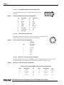
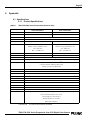
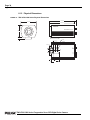
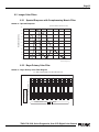
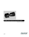
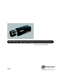
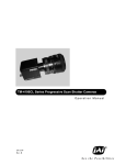
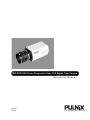
TMC-6700/1000 Series Progressive Scan CCD Digital Color Camera
Operation Manual
69-0117
Rev. A
Imaging Products
Page i
Notice Page
Notice
The material contained in this manual consists of information that is proprietary to PULNiX America, Inc., and may only be
used by the purchasers of the product. PULNiX America, Inc. makes no warranty for the use of its product and assumes no
responsibility for any errors which may appear or for damages resulting from the use of the information contained herein.
PULNiX America, Inc. reserves the right to make changes without notice.
Warranty
All of our solid-state cameras have a full three-year warranty. If any such product proves defective during this warranty
period, PULNiX America, Inc. will repair the defective product without charge for parts and labor or will provide a replacement in exchange for the defective product. This warranty shall not apply to any damage, defect or failure caused by improper
use or inadequate maintenance and use.
Certifications
CE Compliance
The TMC-6700/1000 series has been certified to conform to the requirements of Council Directive 89/336/EC for electromagnetic compatibility and to comply with the following European Standards:
Immunity:
EN500082-2/1995
Emissions:
EN55011:1991 Class A / CISPR 11
All PULNiX products bearing the CE mark have been declared to be in conformance with the applicable EEC Council Directives. However, certain factory-installed options or customer-requested modifications may compromise electromagnetic compatibility and prohibit use of the CE mark. Please note that the use of interconnect cables that are not properly grounded and
shielded may affect CE compliance.
Contact PULNiX Applications Engineering Department for further information regarding CE compliance.
FCC
This equipment has been tested and found to comply with the limits for a Class A digital device, pursuant to Part 15 of the
FCC Rules. These limits are designed to provide reasonable protection against harmful interference when the equipment is
operated in a commercial environment. This equipment generates, uses and can radiate radio frequency energy and, if not
installed and used in accordance with the instruction manual, may cause harmful interference to radio communications. Operation of this equipment in a residential area is likely to cause harmful interference in which case the user will be required to
correct the interference at his own expense.
WARNING
Changes or modifications to this unit not expressly approved by the party responsible for
FCC compliance could void the user’s authority to operate the equipment.
TMC-6700/1000 Series Operation Manual
PULNiX America, Inc.
1330 Orleans Drive
Sunnyvale, CA 94089
Tel: (408) 747-0300
Tel: (800) 445-5444
Fax: (408) 747-0880
E-mail: [email protected]
www.pulnix.com
TMC-6700/1000 Series Progressive Scan CCD Digital Color Camera
Page ii
Table of Contents
1 Introduction . . . . . . . . . . . . . . . . . . . . . . . . . . . . . . . . 1
1.1
1.2
1.3
1.4
Product Description and Applications . . . . . . . . . . . . . . .
Features . . . . . . . . . . . . . . . . . . . . . . . . . . . . . . . . . . . . .
Functional Options. . . . . . . . . . . . . . . . . . . . . . . . . . . . . .
System Configuration . . . . . . . . . . . . . . . . . . . . . . . . . . .
1
1
3
4
2 Installation . . . . . . . . . . . . . . . . . . . . . . . . . . . . . . . . . 6
2.1 Getting Started. . . . . . . . . . . . . . . . . . . . . . . . . . . . . . . . . 6
2.1.1 Unpacking Instructions . . . . . . . . . . . . . . . . . . . . . . . . . . . . . . . .6
2.1.2 Components List . . . . . . . . . . . . . . . . . . . . . . . . . . . . . . . . . . . .6
2.1.3 Accessories and Options . . . . . . . . . . . . . . . . . . . . . . . . . . . . . .6
2.2 Camera Setup . . . . . . . . . . . . . . . . . . . . . . . . . . . . . . . . . 7
2.2.1
2.2.2
2.2.3
2.2.4
2.2.5
2.2.6
2.2.7
Connector Pin Configurations . . . . . . . . . . . . . . . . . . . . . . . . . .7
Power Supply and Power Cable Setup . . . . . . . . . . . . . . . . . . .9
RS-232C Communication Cable and Connector . . . . . . . . . . . 11
Digital Output Cables . . . . . . . . . . . . . . . . . . . . . . . . . . . . . . . . 11
Analog Output Cable (CBL-2R-15) . . . . . . . . . . . . . . . . . . . . .12
Camera Link Cable (Camera Link models only) . . . . . . . . . . .12
Back-Focusing the Lens. . . . . . . . . . . . . . . . . . . . . . . . . . . . . .13
3 Operation . . . . . . . . . . . . . . . . . . . . . . . . . . . . . . . . . 14
3.1 Camera Rear Panel-Base Only . . . . . . . . . . . . . . . . . . . 14
3.1.1
3.1.2
3.1.3
3.1.4
3.1.5
3.1.6
Shutter Mode Switch . . . . . . . . . . . . . . . . . . . . . . . . . . . . . . . .14
Shutter Speed Control Dial. . . . . . . . . . . . . . . . . . . . . . . . . . . .14
White Balance Control Switch . . . . . . . . . . . . . . . . . . . . . . . . .15
IWB Reset Button. . . . . . . . . . . . . . . . . . . . . . . . . . . . . . . . . . .15
Gamma Control Switch . . . . . . . . . . . . . . . . . . . . . . . . . . . . . .15
Bank Switch . . . . . . . . . . . . . . . . . . . . . . . . . . . . . . . . . . . . . . .15
3.2 Camera Rear Panel Switches and Connectors . . . . . . . 16
3.3 Color Balance Adjustment . . . . . . . . . . . . . . . . . . . . . . . 17
3.3.1
3.3.2
3.3.3
3.3.4
White Balance . . . . . . . . . . . . . . . . . . . . . . . . . . . . . . . . . . . . .17
Camera Gain . . . . . . . . . . . . . . . . . . . . . . . . . . . . . . . . . . . . . .17
Color Matrix . . . . . . . . . . . . . . . . . . . . . . . . . . . . . . . . . . . . . . .17
User-Programmable Functions . . . . . . . . . . . . . . . . . . . . . . . .18
3.4 Camera Link Rear Panel . . . . . . . . . . . . . . . . . . . . . . . . 19
3.5 Asynchronous Reset Full Frame Shutter
Camera Operation . . . . . . . . . . . . . . . . . . . . . . . . . . . . . 19
3.5.1 Asynchronous Shutter . . . . . . . . . . . . . . . . . . . . . . . . . . . . . . .19
3.5.2 Asynchronous Reset and Shutter Speed . . . . . . . . . . . . . . . . .20
4 TMC-6700/1000 Series RS-232C Control . . . . . . . . 22
4.1 RS-232C Control Introduction . . . . . . . . . . . . . . . . . . . . 22
4.1.1 RS-232C Communication Defaults . . . . . . . . . . . . . . . . . . . . .22
4.1.2 RS-232C Command . . . . . . . . . . . . . . . . . . . . . . . . . . . . . . . . .22
4.1.3 RAM Memory Map . . . . . . . . . . . . . . . . . . . . . . . . . . . . . . . . . .22
4.2 Basic Command Code. . . . . . . . . . . . . . . . . . . . . . . . . . 23
4.2.1
4.2.2
4.2.3
4.2.4
Set/Refresh RAM Bank . . . . . . . . . . . . . . . . . . . . . . . . . . . . . .23
Get RAM Bank . . . . . . . . . . . . . . . . . . . . . . . . . . . . . . . . . . . . .23
Save RAM Data Into EEPROM . . . . . . . . . . . . . . . . . . . . . . . .24
Load RAM Data From EEPROM . . . . . . . . . . . . . . . . . . . . . . .24
TMC-6700/1000 Series Progressive Scan CCD Digital Color Cameras
Page iii
Table of Contents
4.2.5 Write 1 Byte Into RAM Bank . . . . . . . . . . . . . . . . . . . . . . . . . . 24
4.2.6 Read 1 Byte From RAM Bank . . . . . . . . . . . . . . . . . . . . . . . . . 25
4.3 Camera Control . . . . . . . . . . . . . . . . . . . . . . . . . . . . . . . .25
4.3.1 VCA Gain . . . . . . . . . . . . . . . . . . . . . . . . . . . . . . . . . . . . . . . . . 25
4.3.2 ADC Offset . . . . . . . . . . . . . . . . . . . . . . . . . . . . . . . . . . . . . . . . 26
4.3.3 ADC Ref. Top . . . . . . . . . . . . . . . . . . . . . . . . . . . . . . . . . . . . . . 26
4.3.4 White Balance . . . . . . . . . . . . . . . . . . . . . . . . . . . . . . . . . . . . . 27
4.3.5 Edge Enhancement . . . . . . . . . . . . . . . . . . . . . . . . . . . . . . . . . 27
4.3.6 RGB to YCrCb Conversion . . . . . . . . . . . . . . . . . . . . . . . . . . . 28
4.3.7 Shutter . . . . . . . . . . . . . . . . . . . . . . . . . . . . . . . . . . . . . . . . . . . 28
4.3.8 Gamma Conversion . . . . . . . . . . . . . . . . . . . . . . . . . . . . . . . . . 29
4.3.9 Color Matrix . . . . . . . . . . . . . . . . . . . . . . . . . . . . . . . . . . . . . . . 29
4.3.10Black Level Reference. . . . . . . . . . . . . . . . . . . . . . . . . . . . . . . 30
5 Troubleshooting . . . . . . . . . . . . . . . . . . . . . . . . . . . . 31
5.1 Problems and Solutions . . . . . . . . . . . . . . . . . . . . . . . . .31
5.1.1
5.1.2
5.1.3
5.1.4
Symptom: No Video . . . . . . . . . . . . . . . . . . . . . . . . . . . . . . . . . 31
Symptom: Dark Video . . . . . . . . . . . . . . . . . . . . . . . . . . . . . . . 31
Symptom: Non-synchronized Video. . . . . . . . . . . . . . . . . . . . . 31
Symptom: Bright Video . . . . . . . . . . . . . . . . . . . . . . . . . . . . . . 31
5.2 Information and Support Resources . . . . . . . . . . . . . . . .32
6 Appendix . . . . . . . . . . . . . . . . . . . . . . . . . . . . . . . . . 33
6.1 Specifications . . . . . . . . . . . . . . . . . . . . . . . . . . . . . . . . .33
6.1.1 Product Specifications . . . . . . . . . . . . . . . . . . . . . . . . . . . . . . . 33
6.1.2 Physical Dimensions . . . . . . . . . . . . . . . . . . . . . . . . . . . . . . . . 34
6.2 Imager Color Filters. . . . . . . . . . . . . . . . . . . . . . . . . . . . .35
6.2.1 Spectral Response with Complementary Mosaic Filter . . . . . . 35
6.2.2 Bayer Primary Color Filter . . . . . . . . . . . . . . . . . . . . . . . . . . . . 35
6.3 TMC-6700/1000 Series Control Parameter
Address Map . . . . . . . . . . . . . . . . . . . . . . . . . . . . . . . . . .36
6.4 Digital Output Wave Forms . . . . . . . . . . . . . . . . . . . . . . .37
TMC-6700/1000 Series Progressive Scan CCD Digital Color Cameras
Page iv
List of Figures
FIGURE 1.
TMC-6700/1000 (Base models only) Series System Configuration . .4
FIGURE 2.
TMC-6700CL/1000CL (Camera Link models only)
Series System Configuration . . . . . . . . . . . . . . . . . . . . . . . . . . . . . . .4
FIGURE 3.
12P-02S Interface Cable (optional) . . . . . . . . . . . . . . . . . . . . . . . . .10
FIGURE 4.
CBL-RS232-9 Cable. . . . . . . . . . . . . . . . . . . . . . . . . . . . . . . . . . . . . 11
FIGURE 5.
Direct Channel Link Cable (15CL-02-15) (base only) . . . . . . . . . . . 11
FIGURE 6.
Analog Output Cable (CBL-2R-15). . . . . . . . . . . . . . . . . . . . . . . . . .12
FIGURE 7.
TMC-6700/1000 Series Rear Panel . . . . . . . . . . . . . . . . . . . . . . . . .14
FIGURE 8.
Camera Link Rear Panel . . . . . . . . . . . . . . . . . . . . . . . . . . . . . . . . .19
FIGURE 9.
Asynchronous Reset . . . . . . . . . . . . . . . . . . . . . . . . . . . . . . . . . . . .20
FIGURE 10. External Pulse Width Control . . . . . . . . . . . . . . . . . . . . . . . . . . . . . .21
FIGURE 11. TMC-6700/1000 Series Physical Dimensions . . . . . . . . . . . . . . . . .34
FIGURE 12. Spectral Response . . . . . . . . . . . . . . . . . . . . . . . . . . . . . . . . . . . . . .35
FIGURE 13. Bayer Primary Color Filter Diagram . . . . . . . . . . . . . . . . . . . . . . . . .35
FIGURE 14. Line Data Valid (TMC-1000/1000CL) . . . . . . . . . . . . . . . . . . . . . . . .37
FIGURE 15. Frame Data Valid (TMC-1000/1000CL) . . . . . . . . . . . . . . . . . . . . . .37
FIGURE 16. Line Data Valid (TMC-6700/6700CL) . . . . . . . . . . . . . . . . . . . . . . . .37
FIGURE 17. Frame Data Valid (TMC-7600/6700CL) . . . . . . . . . . . . . . . . . . . . . .38
TMC-6700/1000 Series Progressive Scan CCD Digital Color Camera
Page v
List of Tables
TABLE 1.
15-Pin SVGA Output Connector Configuration . . . . . . . . . . . . . . . . . 8
TABLE 2.
6-Pin Connector Pinout Configuration . . . . . . . . . . . . . . . . . . . . . . . . 8
TABLE 3.
26-Pin CL Connector Pinout Configuration . . . . . . . . . . . . . . . . . . . . 8
TABLE 4.
Shutter Speed Control Settings (Factory Default) . . . . . . . . . . . . . . 15
TABLE 5.
Camera Rear Panel Switches . . . . . . . . . . . . . . . . . . . . . . . . . . . . . 16
TABLE 6.
Camera Rear Panel Connectors . . . . . . . . . . . . . . . . . . . . . . . . . . . 17
TABLE 7.
TMC-6700/1000 Series Product Specifications Table . . . . . . . . . . . 33
TMC-6700/1000 Series Progressive Scan CCD Digital Color Camera
August 14, 2003
TMC-6700/1000 Series Progressive
Scan CCD Digital Color Camera
Operation Manual
Models:
TMC-1000, TMC-1000CL,
TMC-6700, TMC-6700CL
1
Introduction
1.1 Product Description and Applications
The TMC-6700/1000 series* cameras are digital process and output color video cameras which use a
1"(TMC-1000) and 1/2" (TMC-6700) high-resolution progressive scan interline transfer CCD. This
camera series is specially designed to capture images in progressive scan (non-interlace) format,
producing a full frame of electronic shutter image as well as normal images.
The TMC-6700/1000 series cameras are excellent in applications such as dynamic motion capturing,
still-picture storage, on-line inspection, gauging, printing, high-definition graphics and high-resolution
surveillance where high-quality color images are required.
1.2 Features
•
RGB primary color 1" (TMC-1000/CL) 1/2" (TMC-6700/CL) progressive scanning interline
transfer CCD imager
The TMC-1000/6700 series has a color filter array (CFA) called a “Bayer CFA.” It comprises a
ratio of two green pixels for every one red or blue pixel. This staggered structure results in color
that is perceptually true to the human eye. The primary color Bayer CFA progressive scan interline
transfer CCD combines excellent resolution (1008 H x 1018 V) and color fidelity with superb
electronic shutter capability.
•
Full digital processing using real-time DSPs
PULNiX’s state-of-the-art DSP technology offers increased speed, greater efficiency and
specialization of function.
•
RS-232C external control
*. Unless specified, all references to the TMC-1000 and TMC-6700 are relevant to the CL versions of
those cameras as well.
TMC-6700/1000 Series Progressive Scan CCD Digital Color Camera
Page 2
Introduction
The built-in Digital Signal Processor (DSP) is controlled via RS-232C communication for remotely
adjusting color matrix, white balance, gain, edge enhancement, and other functions.
•
Progressive Scanning
The TMC-6700/1000 series uses a state-of-the-art progressive scanning interline transfer CCD,
which scans all lines sequentially from top to bottom at one frame rate (15Hz in TMC-1000, 60Hz
in TMC-6700). In comparison, conventional “TV-format” scanning captures every other horizontal
line (ODD and EVEN lines) at a 60Hz rate per field, completing the scanning with two fields (one
frame) at a 30Hz rate. Like a non-interlace computer screen, progressive scanning generates a crisp,
stable image without alternating lines and provides full vertical resolution. The interline transfer
architecture is essential in generating simultaneous shuttering, as compared with full-frame
architecture which requires mechanical shuttering or a strobe light to freeze the object motion.
•
Progressive scan output in 24-bit LVDS Channel Link™* Digital and RGB analog format
(TMC-1000 nd TMC-6700 base models only)
The digital output is 24-bit LVDS Channel Link output. Channel Link is a transmitter/receiver
chipset pair developed by National Semiconductor for high-speed data transmission. Originally
designed for flat-panel display technologies, Channel Link lends itself to digital video transmission
and has been adopted by PULNiX in their latest cameras. Visit PULNiX’s website at
www.pulnix.com for information on Channel Link-compatible frame grabbers.
Channel Link offers two main advantages:
- Smaller cables
A Channel Link transmitter converts 28 bits of data into four LVDS parallel data streams.
A transmit clock is transmitted with the data over a fifth line. So during every clock
cycle, 28 bits of data are transmitted over only 5 LVDS lines.
As an example, for a 24-bit RGB camera, at least 27 pairs of wires (data and timing) are
needed to transfer the data. The required cable, with 54 wires, would be bulky, heavy, and
expensive.
Using Channel Link technology, the same data can be transferred using only 11 conductors (4 data pairs, one clock pair, and a minimum of 1 ground). This provides an 80%
reduction in cable width, reducing the connector size and cost, as well as requirements
for shielding.
- Higher data rates
A Channel Link transmitter can send data rates up to 2.38GB/sec, (depending on the
transmitter) more than satisfying what is available with today’s camera technology and
offering compatibility with the solutions of the future.
•
Camera Link Digital Output
Camera Link is a camera-to-frame grabber interface specification based on an implementation of
Channel Link technology. The Camera Link standard includes data transmission, hardware (cable
connectors), camera control, and asynchronous serial communications, all on a single cable.
•
*Built-in YCrCb 4:4:4 and 4:2:2 converter
The TMC-6700/1000 series cameras can output three different digital video outputs: 24-bit RGB,
24-bit 4:4:4 YCrCb, and 16-bit 4:2:2 YCrCb.
•
Full-frame electronic shutter, 1/15 sec. to 1/16,000 sec.
The substrate drain-type shutter mechanism provides a clear, crisp image without smearing.
Progressive scanning permits a full frame of image resolution (1008 lines TMC-1000; 484 lines
*. Channel Link is a trademark of National Semiconductor.
TMC-6700/1000 Series Progressive Scan CCD Digital Color Camera
Page 3
Introduction
TMC-6700) per shutter or integration. The user can assign any shutter speed to any of the preset
shutter positions.
•
Asynchronous reset and shutter
The TMC-6700/1000 series cameras asynchronous reset operates with internal sync or external HD
for phase locking. There are three modes to control the asynchronous reset and shutter speed.
•
Integration
The CCD imager of the TMC-6700/1000 series can be exposed for longer than one frame duration
(1/15 sec. TMC-1000; 1/60 sec. TMC-6700). This feature provides sensitivity for low-light
application environments.
•
External Sync Control
The TMC-6700/1000 series cameras accept HD and VD inputs from an external sync generator.
•
Anti-smear filter
Like all PULNiX color cameras, the TMC-6700/1000 series cameras contain a filter to minimize
smear that can result when shooting a very bright object. Smear should only occur under extremely
bright and pointed light source conditions.
•
Three-Year Warranty
The CCD solid-state image sensor allows the camera to maintain a superior performance level
indefinitely while requiring virtually no maintenance. PULNiX backs all of the TMC Series
cameras with a three-year warranty.
Warning:
Unscrewing the camera cover or opening the camera in any
way without prior written permission will void this warranty.
1.3 Functional Options
Contact factory for information on current options.
TMC-6700/1000 Series Progressive Scan CCD Digital Color Camera
Page 4
Introduction
1.4 System Configuration
Figure 1(below) presents a typical system configuration for the base model.
FIGURE 1.
TMC-6700/1000 (Base models only) Series System Configuration
15CL-02 or 15CL-02-15
MAN ASY
SHUTTER
78
IWB G1.0 BANK1
EWB 0.45 BANK2
2 34
9 01
IWB
RST
56
POWER
Power Supply
PD-12UUP
DIGITAL
RS
232
CBL-RS232-C9
ANALOG
CBL-2R-15
Or
Power and
Sync
CBL-2R-15 or 15-pin SVGA cable*
12P-02S
SVGA
Color Monitor
Or
Computer with
Frame Grabber
Board
*TMC-6700 series only
FIGURE 2.
TMC-6700CL/1000CL (Camera Link models only) Series System Configuration
26CL-02-26
CAMERA LINK
POWER
ANALOG
Power Supply
PD-12UUP
CBL-2R-15
or
Power and
Sync
12P-02S
CBL-2R-15 or 15-pin SVGA cable
(TMC-6700CL series only)
SVGA
Color Monitor
or
Computer with
Frame Grabber
Board
TMC-6700/1000 Series Progressive Scan CCD Digital Color Camera
Page 5
Introduction
•
Power supply
Use the optional PD-series power supply or use cable 12P-02S (optional) that connects to the
camera’s 12-pin Hirose connectors on one end and has flying heads for power and sync signals on
the other end.
•
Display monitor
Use cable CBL-2R-15 (optional) or a 15-pin SVGA cable to connect to an SVGA color monitor.
•
Digital output
Use cable 15CL-02 (optional) to connect the camera to a Channel Link™-input frame grabber, or
use cable 15CL-02-15 (optional) connect the camera to a TTL-input frame grabber. (TMC-6700
series only)
•
Analog output
Use cable CBL-2R-15 (optional) to connect the camera to an analog frame grabber.
•
Serial communication
Use cable CBL-RS232-C9 (optional) to connect the camera to a PC for setup.
TMC-6700/1000 Series Progressive Scan CCD Digital Color Camera
Page 6
Installation
2
Installation
The following instructions are provided to help you to set up your video camera system quickly and
easily. We suggest that you read through these instructions prior to unpacking and setting up your
camera system.
2.1 Getting Started
2.1.1 Unpacking Instructions
We recommend that you save the original packing cartons for the cameras and lenses in case you need to
return or exchange an item. We also recommend that any equipment being sent to another location for
field installation be bench-tested to assure that everything is fully operational as a system.
2.1.2 Components List
Please begin by checking your order against the Components List (below) to assure that you have
received everything as ordered, and that nothing has been overlooked in the packing materials. If any
item is missing, please contact your PULNiX representative immediately.
•
TMC-6700 or 1000 series camera
•
TMC-6700 or 1000 data sheet
•
TMC-6700/1000 series operation manual
•
TMC-6700/1000 series software manual
2.1.3 Accessories and Options
Following is a list of additional accessories and options that may be recommended or required for your
particular application. Please check with your PULNiX representative prior to the installation of your
video system to determine what you might need.
•
Direct Channel Link cable: 15CL-02-15 (base TMC-1000 and TMC-6700 only).
•
RS-232 controller set: CS-232C (base only)
•
RGB cable: CBL-2R-15
•
Power supply and power cables: please refer to Section 2.2.2 on page 9.
TMC-6700/1000 Series Progressive Scan CCD Digital Color Camera
Page 7
Installation
2.2 Camera Setup
2.2.1 Connector Pin Configurations
2.2.1 (a)
12-Pin Connector
1
The TMC-6700/1000 series has a 12-pin connector (PC-12P) on the
rear panel for power input and integration control.
2.2.1 (b)
Pin
Description
Pin
Description
1
GND
7
VD In
2
+12V DC
8
GND
3
GND
9
HD In
4
N/C
s10
N/C
5
GND
11
Integ Cont
6
Vinit
12
GND
2
3
9
11
4
8
10
7
12
5
6
15-Pin Digital Connector (base only)
The TMC-6700/1000 series has a 15-pin digital connector (MP221015-243-2200) on the rear panel to output 24-bit digital video and
other digital sync signals via Channel LinkTM.
Pin
Description
Pin
Description
1
CH CLK+
9
CH CLK-
2
CH0+
10
CH0-
3
CH1+
11
CH1-
4
CH2+
12
CH2-
5
CH3+
13
CH3-
6
D_VINIT+
14
D_VINIT-
7
D_INTEG+
15
D_INTEG-
8
GND
pin 8
pin 15
TMC-6700/1000 Series Progressive Scan CCD Digital Color Camera
pin 1
pin 9
Page 8
Installation
2.2.1 (c)
15-pin SVGA Output Connector (base only)
pin 1
The analog RGB output connector is a high-density D-Sub 15-pin
connector.
TABLE 1.
pin 6
15-Pin SVGA Output Connector Configuration
pin 11
2.2.1 (d)
Pin
Description
Pin
Description
1
Red
9
N/C
2
Green
10
N/C
3
Blue
11
GND
4
GND
12
N/C
5
GND
13
H Sync
6
Red GND
14
V Sync
7
Green GND
15
N/C
8
Blue GND
6-Pin Connector (base only)
The TMC-6700/1000 series has a 6-pin connector for RS-232C communication. A
mating 6-pin connector (PC-6P) can be obtained from PULNiX.
TABLE 2.
6-Pin Connector Pinout Configuration
6
5
Pin
Description
1
RS-232 RX
2
RS-232 TX
3
reserved
4
GND
5
GND
6
GND
2
4
Standard
2.2.1 (e)
1
3
26-Pin CL Connector Pinout (CL Models)
The TMC-1000/6700 series has a 26-pin MDR26 connector (3M part number 10226-6212VC) on the
rear panel to output Camera Link data. The connector pin-out is shown in Table 3 below.
TABLE 3.
26-Pin CL Connector Pinout Configuration
Camera Link Connector MDR 26-Pin Connector 10226-6212VC
Pin #
Description
1
GND
2
Tx OUT 0-
3
4
I/O
Pin #
Description
I/O
14
GND
(Shield)
Out
15
Tx OUT 0+
Out
Tx OUT 1-
Out
16
Tx OUT 1+
Out
Tx OUT 2-
Out
17
Tx OUT 2+
Out
TMC-6700/1000 Series Progressive Scan CCD Digital Color Camera
Page 9
Installation
TABLE 3.
26-Pin CL Connector Pinout Configuration (Continued)
Camera Link Connector MDR 26-Pin Connector 10226-6212VC
Pin #
Description
I/O
Pin #
Description
I/O
5
Tx CLK OUT -
Out
18
Tx CLK OUT +
Out
6
Tx OUT 3 -
Out
19
Tx OUT 3+
Out
7
SerTC+
In
20
SerTC -
In
8
SerTFG-
Out
21
SerTFG+
Out
9
VINIT - (CC1-)
In
22
VINIT + (CC1+)
In
10
INTEG + (CC2+)
In
23
INTEG- (CC2-)
In
11
N/C
24
N/C
12
N/C
25
N/C
13
GND
26
GND
2.2.2 Power Supply and Power Cable Setup
2.2.2 (a)
Power Supplies
The TMC-6700/1000 series requires 12V DC. Power is obtained through the 12-pin connector located
at the rear of the camera. PULNiX recommends the following power supplies:
K25-12
110V AC/12V DC
2.1A power supply
K50-12
110V AC/12V DC
4.2A power supply
PD-12UU
110V AC/12V DC
0.5A power supply
PD-12UUP
12-pin connector
US plug
PD-12UE
110V AC/12V DC
0.5A European power supply
PD-12UEP
12-pin connector
European plug
For users providing power through the 12-pin connector, the PD-12P, PD-12UUP, and PD-12UEP
power supplies are available with the 12-pin mating connector already attached to the leads from the
power supply. The PD-12 power supply can be connected to the PULNiX power cable via a terminal
strip or directly.
When wiring the PD-12 power supply directly, please note the following:
•
The lead ends must be twisted together and tin-soldered for strength and electrical continuity.
•
Shrink tubing or a similar insulator should be used to prevent exposed leads from touching and
shorting.
•
The +12V lead is marked with a red stripe or white lettering; be sure not to reverse the leads.
•
All connections must be properly insulated to prevent shorting.
TMC-6700/1000 Series Progressive Scan CCD Digital Color Camera
Page 10
Installation
2.2.2 (b)
PULNiX Power Cables
If you are using PULNiX power cables, such as the 12P-02S, please refer to the12-pin connector pin-out
diagram in Section 2.2.1 on page 7. The cable pin-out diagram is shown below in Figure 3. The colorcoded leads use Gray for Ground and Yellow for +12V DC.
WARNING: When applying power to the camera, using one of the 12-P
series cables, make sure that none of the exposed leads on the
multiple conductor cables are touching, as this may cause damage to the camera.
FIGURE 3.
12P-02S Interface Cable (optional)
+12 V
GND (Gray)
Power (Yellow)
Video Out (Red Coax)
HD In (White Coax)
VD In (Black Coax)
12P-02S Interface Cable
Note:
Pin#
Lead Color
Function
Pin#
Lead Color
Function
1
Gray
GND
7
Black coax signal
VD IN
2
Yellow
+12V DC
8
White shield
GND
3
Red shield
GND
9
White coax signal
HD IN
4
Red coax signal
N/C
10
Brown
N/C
5
Orange shield
GND
11
Blue
INTEG CONT
6
Orange coax signal
VINIT
12
Black shield
GND
Make sure that the unused leads are not touching and that there is no possibility that the
leads could short due to exposed wires.
2.2.2 (c)
Building Your Own Power Cable
Please refer to the 12-pin connector (PC-12P) pin-out in Section 2.2.1 on page 7. Connect the Ground
lead to Pin #1, and the +12V DC (0.5A) lead to Pin #2 of the 12-pin connector.
2.2.2 (d)
Attaching the Power Cable to the Connector
The 12-pin connector is keyed and will fit in only one orientation. Follow these directions to properly
attach the power cable to the camera connector:
1.
Rotate the connector while applying slight pressure until the keyway lines up.
2.
Press the connector into place until it is firmly seated.
3.
Plug the power cord into the 110V AC socket. This will power up the camera.
TMC-6700/1000 Series Progressive Scan CCD Digital Color Camera
Page 11
Installation
2.2.3 RS-232C Cosmmunication Cable and Connector
FIGURE 4.
CBL-RS232-9 Cable
6 1
5
1
6
5
9
2
4 3
2,000.0mm ±25mm (2 meters)
The RS-232 controller set CS-232C includes CBL-RS232-9 interface cable, software diskette, and a
quick-start card. The TMC-6700/1000 series camera’s built-in DSP chip can be controlled by an
external RS-232C interface. The camera settings can be programmed or changed using the
communication cable and software. Please refer to the software manual for details on the graphical user
interface.
2.2.4 Digital Output Cables
The selection of an appropriate digital output cable depends on whether you are using a Channel Link
frame grabber or a non-Channel Link frame grabber. PULNiX offers two digital output cables. The
Channel Link/TTL Adapter cable (15CL-02) provides 24 bit TTL output for use with a non-Channel
Link frame grabber. The Direct Channel Link cable (15CL-02-15) should be used with a Channel Link
frame grabber. Please check PULNiX’s website (www.pulnix.com) for a list of compatible Channel
Link frame grabbers.
2.2.4 (a)
FIGURE 5.
Direct Channel Link Cable
Direct Channel Link Cable (15CL-02-15) (base only)
6
15
8
9
1
1
11
15
5
25.0mm±2mm
10
2,000mm ± 10mm(2 meters)
This cable is for use with Channel Link frame grabbers. It has a 15-pin Airborne connector on the
camera end and a 15-pin high-density, D-sub connector on the frame-grabber end.
Not all Channel Link frame grabbers have a 15-pin input connector, in which case a custom adapter
cable will be needed. The pin assignment for the digital connector is show in Section 2.2.1 (b on page 7.
Contact your PULNiX representative if you need assistance.
TMC-6700/1000 Series Progressive Scan CCD Digital Color Camera
Page 12
Installation
2.2.5 Analog Output Cable (CBL-2R-15)
FIGURE 6.
Analog Output Cable (CBL-2R-15)
6 FEET REF.
(1.83 METERS)
6 INCHES (REF.)
(15.9 CM)
RED
HDB15 MALE
HIGH DENSITY
D-SUB CONNECTOR
GREEN
PIN 1
BNC
PLUGS
(5)
BLUE
PIN 14
BLACK
AY
V
GR
OR
W
HI
TE
VERT.
SYNC
1
H
HORIZ.
SYNC
The RGB analog cable has a 15-pin high-density D-sub connector on the camera end, and five BNC
connectors on the frame-grabber end.
Not all frame grabbers have BNC analog input connectors, in which case a custom adapter cable will be
needed. Contact your PULNiX representative if you need assistance.
2.2.6 Camera Link Cable (Camera Link models only)
The MDR26 cable assembly (26CL-02-26) from 3M (part number 10226-6212VC) has been
standardized as the Camera Link cable. This cable has the 26-pin MDR26 connector on both ends. This
is a straight-through cable. The pin-out configuration is shown in Table 3 on page 8.
2
16
3
17
4
18
5
19
6
20
7
21
8
22
9
23
10
24
11
25
12
26
13
11
24
23
8
21
20
6
19
5
3
16
2
15
1
14
4
18
7
9
10
12
13
15
25
1
22
14
2X
Thumbscrews
26
26 Position
High Density
Mini D Ribbon
(MDR) Male Plug
Cable
17
26 Position
High Density
Mini D Ribbon
(MDR) Male Plug
2X
Thumbscrews
TMC-6700/1000 Series Progressive Scan CCD Digital Color Camera
Page 13
Installation
2.2.7 Back-Focusing the Lens
Follow these directions to back-focus the TMC6700/1000 series camera.
1.
Attach a C-mount lens to the camera. Be sure
that the lens is properly mounted.
2.
Loosen the three miniature set screws holding
the focus ring.
3.
Set the lens focus to infinity.
4.
Point the camera at a distant object and turn
the focus ring to obtain the best possible focus.
5.
Set Screws (quantity 3)
Lens
Back-Focus Ring
Tighten the focus-ring set screws. Your backfocus is now set.
TMC-6700/1000 Series Progressive Scan CCD Digital Color Camera
Page 14
Operation
Operation
3.1 Camera Rear Panel-Base Only
FIGURE 7.
TMC-6700/1000 Series Rear Panel
White Balance Reset
IWB RST (3)
Shutter Mode Switch (2)
White Balance Control (4)
Gamma Control Switch (5)
MAN ASY
IWB
RST
78
9 01
Bank Switch (6)
2 34
Shutter Dial (1)
IWB G1.0 BANK1
EWB 0.45 BANK2
SHUTTER
56
POWER
DIGITAL
RS-232 (7)
RS
232
Power (10)
Analog (8)
ANALOG
Digital (9)
3.1.1 Shutter Mode Switch
The Shutter Mode Switch selects between Manual (MAN) Shutter Mode and Asynchronous (ASY)
Shutter Mode. Table 4, “Shutter Speed Control Settings (Factory Default),” on page 15 lists shutter
speeds for Manual and Async Modes. When Async (ASY) Mode is selected, live image data is not sent
out except with Asynchronous Reset. See Figure 9 on page 20 for more information.
3.1.2 Shutter Speed Control Dial
78
9 01
TMC-6700/1000 Series Progressive Scan CCD Digital Color Camera
2 3
Shutter speed can be selected by switching the shutter dial to the appropriate
setting (0 through 9). In the factory default value, the settings correspond to
the shutter speeds as follows in Table 4 on page 15. Each position can have
any shutter speed by assigning a value to the proper register address, using the
RS-232 software control.
4 56
3
Page 15
Operation
Note:
TABLE 4.
In order to avoid video problems, make sure that you turn the shutter-speed control dial
quickly. If you turn the dial too slowly, the shutter may not expose for the proper period of
time, resulting in either no video or bright video. If this happens, push the IWB RST switch
on the rear panel or repeat the dial change at a faster speed.
Shutter Speed Control Settings (Factory Default)
Position
Manual (MAN) Shutter
Async (ASY) Shutter
0
no shutter
no shutter with VINIT reset
1
256H
1/60
1.0H
1/16,000
2
128H
1/125
2.0H
1/8,000
3
64H
1/250
4.0H
1/4,000
4
32H
1/500
8.0H
1/2,000
5
16H
1/1,000
16H
1/1,000
6
8H
1/2,000
32H
1/500
7
4H
1/4,000
64H
1/250
8
2H
1/8,000
128H
1/125
9
1H
1/16,000
Pulse Width Control
3.1.3 White Balance Control Switch
The IWB/EWB switch selects between Internal White Balance (IWB) mode and External White
Balance (EWB) mode. When the IWB RST button is pressed, white balance is calibrated. When the
IWB RST button is released, the last calibration value is held internally. EWB preset values can only be
changed via RS-232C control.
3.1.4 IWB Reset Button
When held down, the IWB reset button calibrates the white balance so that the selected object appears
to be white. After it is released, the camera maintains the last white balance values.
3.1.5 Gamma Control Switch
The gamma control switch selects between gamma 1.0 and gamma 0.45.
3.1.6 Bank Switch
The camera features four memory banks that store camera configuration parameters such as shutter
speed, color matrix, white balance, gain, and edge enhancement. The first two banks, Bank1 and Bank2,
can be selected via the Bank Switch on the back panel of the camera. Bank3 and Bank4 can be selected
via RS-232C control. This feature allows easy switching between different camera-control parameters
as application needs change. Please refer to Section 4.1.2 on page 22.
TMC-6700/1000 Series Progressive Scan CCD Digital Color Camera
Page 16
Operation
3.2 Camera Rear Panel Switches and Connectors
The following two charts list and describe the features of the camera rear panel illustrated in Figure 7.
Table 5 on page 16 contains information on the switches on the rear panel and Table 6 on page 17
contains information on connectors on the rear panel.
TABLE 5.
Camera Rear Panel Switches
#
Switch
Mode
Description
Action
1
Shutter dial
0 to 9 positions,
Manual (MAN)
Mode
Shutter speed
control dial for
manual shutter
mode
Please refer to Table 4 on page 15 for shutter
speeds.
0 to 9 positions.
Asynchronous
(ASY) Reset
Mode
Shutter speed
control dial for
asynchronous
shutter mode.
MAN
Manual Shutter
Mode
Camera continuously outputs video at 15FPS.
ASY
Asynchronous
Shutter Mode
Camera resets on Vinit signal: pin 6 of 12-pin
connector.
Held down
White Balance
Reset switch
Calibrates the white balance so that the selected
object appears to be white.
2
3
4
5
6
Shutter Mode
Switch
White Balance Reset
IWB RST
White Balance Control
Released
Camera maintains the last white balance values
and holds the calibration internally.
IWB
Internal White
Balance
Selects Internal White Balance mode. In the
IWB mode, when the IWB reset RST button is
pushed, the camera internally adjusts R and B
white balance so that the white object is viewed
as white under particular light conditions.
EWB
External White
Balance
Selects External White Balance mode. When
EWB mode is set, the external WB-R and WBB offsets are loaded from RAM. EWB preset
values can be changed via RS-232C only, i.e,
WB-R and WB-B offsets in RAM can be
updated by software.
Gamma Control Switch
G1.0
Gamma 1.0
Selects Gamma 1.0
G0.45
Gamma 0.45
Selects Gamma 0.45
Bank Switch
Bank1
Bank1 selection
switch
Selects Bank1 camera parameter set.
Bank2
Bank2 selection
switch
Selects Bank2 camera parameter set
NOTE: Bank3 and Bank4 can be selected via
RS-232C control.
TMC-6700/1000 Series Progressive Scan CCD Digital Color Camera
Page 17
Operation
TABLE 6.
Camera Rear Panel Connectors
#
Connector
Type
Cable Needed
Cable Information
7
RS-232
6-pin female connector
CBL-RS232-C9
Connect PC to the camera using
the RS-232C control cable (CBLRS232-C9). This cable is a part of
the communication kit (CS-232C).
8
Analog
15-pin High Density
D-sub female connector
CBL-2R-15
If you are using a monitor or frame
grabber that needs Red, Green,
Blue, Vertical Sync, and Horizontal Sync, then use the RGB analog
cable (CBL-2R-15).
9
Digital
15-pin female Airborne
connector
15CL-02 or 15CL02-15
Use the Channel Link/TTL adapter
cable (15CL-02) if you are using a
non-Channel Link frame grabber
that needs TTL input. Use the
Direct Channel Link cable (15CL02-15) if you are using a Channel
Link frame grabber.
10
Power/Sync
12-pin Hirose male
connector
12P-02S cable or
PD-12P power
supply
Connect a 12V DC power supply
(K25-12V or PD-12) using power
cable 12P-02S* or connect power
supply PD-12P.
*See Figure 3 on page 10 for Sync, VD, HD, and VINIT pinout.
3.3 Color Balance Adjustment
3.3.1 White Balance
Internal WB and External WB modes are available either via the rear panel switch or through RS-232
software control. In internal WB mode when the IWB Reset Button is pushed, the TMC-6700/1000
series internally adjusts R and B white balance so that the white object is viewed as white under the
particular light conditions. When external WB mode is set, the external WB-R and WB-B offset are
loaded from RAM. WB-R and WB-B offsets in RAM can be updated by software.
3.3.2 Camera Gain
The TMC-6700/1000 series supports VCA (Voltage Controlled Amplifier) gain control and DSP
(Digital Signal Processing) gain control. DSP gain is supplementary control for users requiring fine
tuning.
3.3.3 Color Matrix
Color matrixing is an operation designed to improve the color rendition and color saturation of the
image. The matrixing corrects the spectral sensitivities of the image sensor for the chromaticities of the
display. This significantly improves the subjective quality of the image, since it allows the tone and
color reproduction to be optimized, which also improves the apparent contrast and sharpness of the
system.
TMC-6700/1000 Series Progressive Scan CCD Digital Color Camera
Page 18
Operation
The mathematical transformation is a linear-space 3 x 3 matrix operation, as shown below.
1.75 – 0.25 – 0.5 Ri
Ro
Go = – 0.1875 1.3125 – 0.125 Gi
– 0.125 – 0.5 – 1.625 Bi
Bo
The coefficients have been optimized for the spectral sensitivities of a Bayer CFA (color filter array).
For camera systems, a linear-space color correction matrix is used. The coefficients are programmable
through the serial interface.
3.3.4 User-Programmable Functions
3.3.4 (a)
Edge Enhancement (Sharpness)
Edge enhancement is set by RS-232 control. Horizontal, vertical, and both H and V enhancement are
selectable. The DSP mathematically manipulates the horizontal and vertical edge information to
sharpen the image. The intensity of the enhancement can be set by Edge Enhancement Level.
3.3.4 (b)
Gamma Selection
You can toggle between 0.45 (default) and 1.0 (linear output) by either the switch on the rear panel or
RS-232 control.
3.3.4 (c)
Shutter Selection
The TMC-6700/1000 series provides manual shutter and asynchronous shutter with external trigger
(VINIT). Each mode is selectable up to 1/16,000 sec. By selecting the shutter dial setting (0 to 9), the
preset shutter duration is loaded from RAM.
The TMC-6700/1000 series also supports Direct shutter mode. In Direct shutter mode, the user can
control any exposed line count within the shutter time range.
3.3.4 (d)
RGB to YCrCb Conversion
The TMC-6700/1000 series can output three different digital video outputs, 24-bit RGB, 24-bit 4:4:4
YCrCb, and 16-bit 4:2:2 YCrCb. Output can be selected by software interface only.
YCrCb conversion is expressed in the following formula:
Y = 0.257R + 0.504G + 0.098B + 16
Cr = 0.439R + 0.368G - 0.071B + 128
Cb = -0.148R - 0.291G + 0.439B + 128
3.3.4 (e)
User Parameter Saving and Loading
User parameters can be stored in EEPROM. However, the user has no direct read/write access to the
EEPROM. RS-232 software permits read/write of the parameters to RAM. Four RAM banks are
available; if the user needs to save the data permanently into EEPROM, then all of the data in the four
TMC-6700/1000 Series Progressive Scan CCD Digital Color Camera
Page 19
Operation
RAM banks can be saved by the EEPROM save command (Section 4.2.3, “Save RAM Data Into
EEPROM,” on page 24).
3.3.4 (f)
Black Level Control
The TMC-6700/1000’s DSP has independent red, green and blue offset controls, and black level
control. The user can calibrate these under specific lighting conditions by using the RS-232 control.
3.3.4 (g)
RS-232 External Communication
The TMC-6700/1000 series is capable of being controlled by external communication via RS-232. This
communication overrules the preset data in the memory pages and the back panel switch settings.
Please refer to Section 4 on page 22 for detailed instructions.
3.4 Camera Link Rear Panel
FIGURE 8.
Camera Link Rear Panel
CAMERA LINK
POWER
ANALOG
3.5 Asynchronous Reset Full Frame Shutter Camera Operation
The TMC-6700/1000 series is designed to accommodate an ON-LINE inspection reset mechanism with
full frame shutter. The shutter speed can be controlled by either an external pulse width or internal
shutter speed control.
3.5.1 Asynchronous Shutter
For the asynchronous shutter mode, async mode needs to be selected either from the rear panel (ASY)
or by RS-232. When the negative reset pulse (VINIT) is applied, the camera will latch the falling edge
to its next horizontal drive and immediately reset the vertical sync timing (Figure 9, “Asynchronous
Reset,” on page 20). The TMC-6700/1000 series asynchronous cameras output a full frame of shuttered
video in progressive format.
TMC-6700/1000 Series Progressive Scan CCD Digital Color Camera
Page 20
Operation
FIGURE 9.
Asynchronous Reset
ASYNC RESET
VINIT
VD
SG (TRANSFER GATE)
DISCHARGE PULSES
VIDEO
Async Image
Stand-by Image
3.5.2 Asynchronous Reset and Shutter Speed
The TMC-6700/1000 series asynchronous reset operates with internal sync or external HD for phase
locking. When VINIT pulse is applied, it resets the camera’s scanning and purges the CCD. There are
three modes to control the asynchronous reset and shutter speed:
•
External VINIT with pulse width control
•
Internal shutter speed with fast mode
•
Internal shutter speed with slow mode
3.5.2 (a)
External Pulse Width Control Mode
To select the external pulse width control mode, set the shutter dial switch to “9.” Apply a VINIT signal
with controlling pulse width, which can be generated from an external event trigger to the camera. The
internal reset pulse will latch to HD. The duration from the first VINIT pulse leading edge to rising
edge, X, controls the shutter speed as follows:
Shutter speed ts = X (1H resolution)
1H = 63.5 µsec.
Min. pulse width = 1H
TMC-6700/1000 Series Progressive Scan CCD Digital Color Camera
Page 21
Operation
FIGURE 10. External Pulse Width Control
External
Pulse
Width
X
(min. 1H)
Hd
Internal Vinit
9H
Transfer Gate
Pulse
18H
Exposure Time
Discharge
pulse
Composite
Video
3.5.2 (b)
Long Integration
With pulse-width control, long integration is possible up to a few seconds besides integration control
(pin #11 of the 12-pin connector).
3.5.2 (c)
Internal Fast Reset Mode (1H~8H, or 1/16,000~1/2,000)
When fast reset mode is selected, the camera resets with internal VINIT timing which is latched to HD.
Video output is also synchronized with internal VINIT timing without further delay. The shutter speed
is controlled by the shutter dial.
3.5.2 (d)
Internal Slow Reset Mode (9H~1048H, or >1/2,000~1/15)
With the Internal Slow Reset mode selected, the camera operates the reset and shutter by the same
means as the wide pulse width control mode. When external VINIT pulse is applied, internal VINIT is
latched to HD and the second internal VINIT signal is generated to set up the shutter speed period.
Video output timing starts right after the second internal VINIT.
TMC-6700/1000 Series Progressive Scan CCD Digital Color Camera
Page 22
TMC-6700/1000 Series RS-232C Control
4
TMC-6700/1000 Series RS-232C Control*
4.1 RS-232C Control Introduction
The TMC-1000’s DSP parameters and operation mode can be controlled by an external RS-232C
interface. The camera features four memory banks that store camera configuration parameters such as
shutter speed, color matrix, white balance, gain, and edge enhancement. The first two banks, Bank1 and
Bank2, can be selected via the Bank Switch on the back panel of the camera. Bank3 and Bank4 can be
selected via RS-232C control. This feature allows easy switching between different camera-control
parameters as application needs change. Each time the camera is turned on, saved data is loaded from
EEPROM to RAM Bank1.
The RS-232C control software does not have direct access to the EEPROM. Users can program the
EEPROM via the RAM banks. For instance, in order to change the gain value, it is necessary to access
the RAM address that holds the gain parameter to send new data to it. The RAM address is shown in
Section 6.3, “TMC-6700/1000 Series Control Parameter Address Map,” on page 36. Section 4.1.3
through Section 4.2.4 explains the following:
•
how to set the RAM bank
•
how to get the current RAM bank number
•
how to save into and load from EEPROM.
Section 4.2.5 and Section 4.3.10 show how to write and read new camera parameters to and from the
RAM bank.
4.1.1 RS-232C Communication Defaults
Parity
Data
Stop
Baud rate
:
:
:
:
None
8-bit
1-bit
9600 bps
If other communication conditions are required, please contact PULNiX.
4.1.2 RS-232C Command
The TMC-6700/1000 series command packet is in 8-bit binary code. When a packet is received by the
TMC-1000, it reads the internal packet of the received buffer. If it is the correct packet, then it processes
the parameters based on the commands detailed in Section 4.2.
4.1.3 RAM Memory Map
Each of four user’s RAM banks is mapped in the Appendix, Section 6.3, “TMC-6700/1000 Series
Control Parameter Address Map,” on page 36.
*. Note: for information on the GUI software, see the TMC-1000/6700 camera control software manual.
TMC-6700/1000 Series Progressive Scan CCD Digital Color Camera
Page 23
TMC-6700/1000 Series RS-232C Control
4.2 Basic Command Code
4.2.1 Set/Refresh RAM Bank
Function:
Set or refresh the RAM bank.
Four user’s RAM banks are available from Bank 1 to Bank 4. Typical situations in
which you may want to use this command are when you want to change to another
RAM bank, and when you want to reflect changes after sending the shutter command,
WB command, etc.
TX Command Code
MSB
7
1
6
0
D3
5
1
4
0
3
D3
2
D2
1
D1
LSB
0
D0
0 : Override Rear Panel Flag Off
1 : Override Rear Panel Flag On
Ram Bank Number -1 (0, 1, 2 or 3) Ex: Bank 1: 00
D2:0
If the “Override Rear Panel” flag is on, the rear panel settings are overwritten by the
software settings. If the flag is off, the rear panel settings reflect on the image.
Note:
The rear panel setting gets priority. Once you change any rear panel setting on the back of
the camera, the parameters reflect the new rear panel setting.
Example:
follows:
Set RAM bank 1 with override panel flag on. The command code packet is sent as
10101000 (BIN) or 168 (DEC)
4.2.2 Get RAM Bank
Function:
Get the number of the RAM bank currently being used.
The current RAM bank number is returned from the camera in response to the
following command code:
TX Command Code
MSB
7
1
6
1
5
1
4
0
3
X
2
X
1
X
LSB
0
X
Bits 3 to 0 are no-care bits. The camera responds as the following 8-bit binary data:
RX Response Code
MSB
7
0
6
0
5
0
4
0
3
D3
2
D2
1
D1
LSB
0
D0
TMC-6700/1000 Series Progressive Scan CCD Digital Color Camera
Page 24
TMC-6700/1000 Series RS-232C Control
D3
D2:0
Rear Panel Override Flag
Ram Bank Number -1 (0, 1, 2 or 3)
D3 is the rear panel override flag, indicating whether the software or the rear panel
has priority regarding parameter control.
Note:
Once any rear panel switch is changed, rear panel control will take priority, and the
configuration of all the rear panel switch settings will apply to the current image:
4.2.3 Save RAM Data Into EEPROM
Function:
Save all four RAM data banks into EEPROM.
All of the data in the four RAM banks can be saved into EEPROM by sending the
following command code:
TX Command Code
MSB
7
1
6
0
5
0
4
0
3
1
2
0
1
1
LSB
0
0
4.2.4 Load RAM Data From EEPROM
Function:
Load config data from EEPROM to all four RAM banks.
Data saved in EEPROM can be loaded from EEPROM into four RAM banks by
sending the following command code:
TX Command Code
MSB
7
1
6
1
5
0
4
0
3
0
2
0
1
0
LSB
0
0
4.2.5 Write 1 Byte Into RAM Bank
Function:
Write 1 byte of data into the location of a specific address in a RAM bank.
After the RAM bank is selected, new 8-bit data can be written to the desired location
of a specific address by sending the following command code:
TX Command Code 1
MSB
7
0
6
1
A5:0
5
A5
4
A4
3
A3
2
A2
1
A1
LSB
0
A0
1
LSB
0
RAM address
TX Command Code 2
MSB
7
6
5
4
3
2
TMC-6700/1000 Series Progressive Scan CCD Digital Color Camera
Page 25
TMC-6700/1000 Series RS-232C Control
D0
D1
D7:0
D2
D3
D4
D5
D6
D7
8-bit data to update
The first command code specifies the RAM address to write. The RAM address is shown in the
Appendix, Section 6.3, “TMC-6700/1000 Series Control Parameter Address Map,” on page 36.
The second command code specifies the new 8-bit data to overwrite.
4.2.6 Read 1 Byte From RAM Bank
Function:
Read 1 byte of data from the location of a specific address in the RAM bank.
8-bit data saved in the RAM bank can be read by sending the following command:
TX Command Code
MSB
7
0
6
0
5
A5
4
A4
3
A3
2
A2
1
A1
LSB
0
A0
1
D1
LSB
0
D0
A5:0RAM Address
R X Response Code
MSB
7
D7
D7:0
6
D6
5
D5
4
D4
3
D3
2
D2
8-bit data received from the camera
The command code to transmit specifies the address of the location from which to
read the data. Please refer to the RAM address map (Section 6.3, “TMC-6700/1000
Series Control Parameter Address Map,” on page 36). If the address is accepted by
the camera, the camera sends the data stored in the address.
4.3 Camera Control
4.3.1 VCA Gain
Saved address:
Representation:
Value:
1
8-bit normal binary
80~100
Write Example: (Write VCA 25 to address 1)
Tx1
01000001
Tx2
10011000 *
Tx3
Refresh RAM Bank
Read Example: (Read address 1, and receive 67)
Tx1
00000001
Rx1
11000010 *
TMC-6700/1000 Series Progressive Scan CCD Digital Color Camera
Page 26
TMC-6700/1000 Series RS-232C Control
*Note: The byte order of the ADC offset, VCA gain and ADC Ref. Top is opposite to that which is
actually seen. For instance, if the user needs to write 48 (00110000 in binary code) as the
new VCA gain, the code for 48 must be sent (00001100).
Note:
The particular RAM bank may be set prior to write or read. The image will not be updated
until you set (refresh) the RAM bank after the write or read operation.
4.3.2 ADC Offset
Saved address:
Representation:
Value:
2
8-bit normal binary
220~240
Write Example: (Write ADC offset 34 to address 2)
Tx1
01000010
Tx2
01000100 *
Tx3
Refresh RAM Bank
*Note: The byte order of the ADC offset, VCA gain and ADC reference data is opposite to that
which is actually seen. Unlike all other data, ADC offset, ADC Ref. Top and VCA gain
have the opposite byte order. For instance, if the user needs to write 48 (00110100 in
binary code) as the new ADC offset, the code for 52 must be sent (00101100).
4.3.3 ADC Ref. Top
Saved address:
Representation:
Value:
3
8-bit normal binary
0~255
Write Example: (Write ADC ref top 25 to address 3)
Tx1
01000011 (address 3, write)
Tx2
10011000 *
Tx3
Refresh RAM Bank
Read Example: (Read address 3, and receive 67)
Tx1
00000011 (address 3, read)
Rx1
11000010 *
*Note: The byte order of the ADC offset, VCA gain and ADC Ref. Top is opposite to that which is
actually seen. For instance, if the user needs to write 48 (00110000 in binary code) as the
new VCA gain, the code for 48 must be sent (00001100).
Note:
The particular RAM bank may be set prior to write or read. The image will not be updated
until you set (refresh) the RAM bank after the write or read operation.
TMC-6700/1000 Series Progressive Scan CCD Digital Color Camera
Page 27
TMC-6700/1000 Series RS-232C Control
4.3.4 White Balance
The white balance mode is saved in address 6 in RAM. If the internal WB mode is set, then the TMC6700/1000 series internally accumulates R and B white balance. If the external WB mode is set, then
the external WB-R and WB-B offset are loaded from address 2B (hex) and 2A (hex) respectively. WBR and WB-B offsets can be updated by accessing addresses 2B and 2A (hex). WB-R and WB-B in these
addresses are 2’s complement representation.
Address 6
MSB
7
Y1
Y1:0
EL1:0
EM1:0
W1
W0
6
Y0
5
EL1
4
EL0
3
EM1
2
EM0
1
W1
LSB
0
W0
RGB to YCrCb Conversion Mode
(0: RGB, 1: 4:4:4 YCrCb, 2: 4:2:2 YCrCb)
Edge enhancement level
(0: max enh. level, 3: min. enh. level)
Edge enhancement mode
(0: Bypass, 1: H, 2: V, 3: H&V)
Hold when Int. WB is selected
(0: Reset, 1: Hold)
White balance mode
(0: Int. WB, 1: Ext. WB)
Example 1
Set Internal Autotracking WB (RGB, Edg Enh Bypass)
Tx1
01000110 (address 6, write)
Tx2
00000010
Tx3
Refresh RAM Bank
Example 2
Set External WB (RGB, H Edge, level 2)
Tx1
01000110 (address 6, write)
Tx2
00100100 (Ex WB, H Edge, level 2, RGB)
Set External WB-R (-30) and WB-B (-20)
Tx3
01101010 (address 0 x 2A)
Tx4
11101100 (WB-B, -20)
Tx5
01101011 (address 0 x 2B)
Tx6
11100010 (WB-R, -30)
Tx7
Refresh RAM Bank
4.3.5 Edge Enhancement
The Edge Enhancement mode is saved in address 6 (please refer to Section 4.3.4 on page 27). The
TMC-6700/1000 series supports Bypass, Horizontal Enh (H), Vertical Enh (V) and H&V mode. Please
refer to Section 4.3.4, “White Balance,” on page 27.
Example
TMC-6700/1000 Series Progressive Scan CCD Digital Color Camera
Page 28
TMC-6700/1000 Series RS-232C Control
Set V Enh and level 3 (RGB, Int. WB)
Tx1
01000110 (address 6, write)
Tx2
00111000
Tx3
Refresh RAM Bank
4.3.6 RGB to YCrCb Conversion
RGB to YCrCb Conversion mode is saved in address 6. The TMC-6700/1000 series supports RGB,
4:4:4 YCrCb and 4:2:2 YCrCb. Please refer to Section 4.3.4, “White Balance,” on page 27.
Example
Set 4:2:2 YCrCb (Edge Enh Bypass, Int. WB)
Tx1
01000110 (address 6, write)
Tx2
10000000
Tx3
Refresh RAM Bank
4.3.7 Shutter
Shutter mode is saved in address 7 in the RAM bank.
In Normal shutter mode (DS=0), Manual and Async can be selected. The shutter speed can be changed
by setting the proper value on the Shutter Dial (0 through 9). If a value is set on the Shutter Dial, then
the preset values for this dial are loaded from different locations of the address in RAM.
Address 7
MSB
7
X
G
DS
AS
D3:0
6
G
5
DS
4
AS
3
D3
2
D2
1
D1
LSB
0
D0
Gamma Conversion Mode
(0: off (1.0), 1: on (0.45))
Direct Shutter Flag
(0: Normal Shutter, 1: Direct Shutter)
Async Shutter Flag
(0: Manual, 1: Async)
Shutter Dial
(0 to 9)
In Direct Shutter mode (DS=1), Manual and Async mode can be selected. In Direct Shutter mode, the
Shutter Dial has no effect; the preset shutter speed value is loaded from address A, B (hex) or 3E, 3F
(Hex) (Async). Users can upload the Direct Shutter preset value by accessing these direct shutter preset
addresses.
In order to convert the exposing line count (H) to direct shutter speed, the following formula is applied:
Direct Shutter Manual:
Shutter Speed = 1049 (dec) - n ------>TMC-1000
524 (dec) - n ------>TMC-6700
Direct Shutter Async:
Shutter Speed = 8-n when n=1H~8H
TMC-6700/1000 Series Progressive Scan CCD Digital Color Camera
Page 29
TMC-6700/1000 Series RS-232C Control
n-1
when n is exposing line count.
when n=9H~1048H----> TMC-1000
when n=9H-523
----> TMC-6700
Example 1
Set Normal Manual Shutter Dial 5 (Gamma on)
Tx1
01000111 (address 7, write)
Tx2
01000101
Tx3
Refresh RAM Bank
Example 2
Set Direct Shutter Async mode (n=1030H, Gamma on)
Tx1
01000111 (Address 7)
Tx2
01110000 (Shutter Mode)
Tx3
01111110 (Address 3E)
Tx4
00000101 (Direct Shutter LSB)
Tx5
01111111 (Address 3F)
Tx6
00000100 (Direct Shutter MSB)
Tx7
Refresh RAM Bank
4.3.8 Gamma Conversion
The Gamma Conversion mode is saved in address 7. The TMC-6700/1000 series supports 1.0 Gamma
mode and 0.45 Gamma mode. Please refer to Section 4.3.6, “RGB to YCrCb Conversion,” on page 28.
Example
Set Gamma on (0.45) (Normal Async Dial 5)
Tx1
01000111 (Address 7)
Tx2
01000101 (Gamma mode)
Tx3
Refresh RAM Bank
4.3.9 Color Matrix
Color Matrix data are saved in the RAM address from 1E to 26 (hex). As discussed in Section 3.3.3,
“Color Matrix,” on page 17, the Color Matrix has 9 coefficients of floating point value. Each (RR,
RG,....BB) is converted into 8-bit 2’s complement representation by first multiplying 32, then extracting
the integer, and finally 2’s complementing the negative number.
Example
Write Default Matrix
CMTX= [ 1.75
-0.1875
-0.125
Tx1
Tx2
Tx3
Tx4
Tx5
-0.25
1.3125
-0.5
-0.5
-0.125
1.625]
01011110 (Address of BB)
00110100
01011111 (Address of BG)
11110000
01100000 (Address of BR)
TMC-6700/1000 Series Progressive Scan CCD Digital Color Camera
Page 30
TMC-6700/1000 Series RS-232C Control
Tx6
Tx7
Tx8
Tx9
Tx10
Tx11
Tx12
Tx13
Tx14
Tx15
Tx16
Tx17
Tx18
Tx19
11111100
01100001 (Address of GB)
11111100
01100010 (Address of GG)
00101010
01100011 (Address of GR)
11111010
01100100 (Address of RB)
11110000
01100101 (Address of RG)
11111000
01100110 (Address of RR)
00111000
Refresh RAM Bank
4.3.10 Black Level Reference
Saved address:
Representation:
Value:
27, 28, 29 (hex)
8-bit 2’s complementary binary
-128~127
Example: Update new Black Level offset values (Rof=-10, Gof=-20, and Bof=-10)
Tx1
01100111 (Address of B offset)
Tx2
11110110
Tx3
01101000 (Address of G offset)
Tx4
11101100
Tx5
01101001 (Address of R offset)
Tx6
11110110
Tx7
Refresh RAM Bank
TMC-6700/1000 Series Progressive Scan CCD Digital Color Camera
Page 31
Troubleshooting
5
Troubleshooting
5.1 Problems and Solutions
Following are troubleshooting tips for common problems. In general, problems can easily be solved by
following these instructions. If the following remedies fail to offer a solution to your problems, please
contact a PULNiX representative.
5.1.1 Symptom: No Video
Remedies: Check that the following are properly operational.
•
Power supplies
•
Power cables
•
Main power source
•
Shutter mode switch (Please refer to the note under Section 3.1.1 on page 14.)
•
Shutter speed control dial (Please refer to the note under Section 3.1.2 on page 14.)
•
Lens
5.1.2 Symptom: Dark Video
Remedies: Check that the following are properly connected and operational.
•
Shutter mode switch (Please refer to the note under Section 3.1.1 on page 14.)
•
Iris opening on the lens
5.1.3 Symptom: Non-synchronized Video
Remedies: Check that the following are properly connected and operational.
•
Proper mode output
•
Frame grabber software camera selection
5.1.4 Symptom: Bright Video
Remedies: Check that the following are properly connected and operational.
•
Shutter speed control dial (Please refer to the note under Section 3.1.2 on page 14.)
•
IWB RST switch
TMC-6700/1000 Series Progressive Scan CCD Digital Color Camera
Page 32
Troubleshooting
5.2 Information and Support Resources
For further information and support:
Phone:
(408) 747-0300
(800) 445-5444
(800) 3-PULNIX (24-hour message access)
Fax:
(408) 747-0660
E-mail:
[email protected]
Mail:
PULNiX America, Inc.
Sales Department
1330 Orleans Drive
Sunnyvale, CA 94089
ATTN: Video Applications
Web Site:
www.pulnix.com
TMC-6700/1000 Series Progressive Scan CCD Digital Color Camera
Page 33
Appendix
6
Appendix
6.1 Specifications
6.1.1 Product Specifications
TABLE 7.
TMC-6700/1000 Series Product Specifications Table
TMC-1000/1000CL
TMC-6700/6700CL
Imager
1” progressive scanning interline transfer CCD
1/2” progressive scanning interline transfer CCD
Pixels
1008 (H) x 1018 (V)
648 (H) x 484 (V)
Cell size
9.0µm x 9.0µm
Color filter
Bayer Primary RGB color filter
Scanning
Sync
Data clock output
Resolution
Progressive, 1050 lines @ 15Hz
Progressive, 525 lines @ 60Hz
Internal/external auto switch
Internal/external auto switch
HD/VD, 4.0 Vp-p impedance 4.7k¾
HD/VD, 4.0 Vp-p impedance 4.7k¾
VD = 15Hz ±5%
VD = 60Hz ±5%
HD = 15.75KHz ±3%
HD = 31.47KHz ±3%
20.034MHz
25.49MHz
Digital: 1006 (H) x 1016 (V)
S/N Ratio
Digital: 646 (H) x 482 (V)
50dB min., 56dB typical
Min. illumination
Video output
10 lux, f = 1.4 9AGC off); Sensitivity: 10µV/eDigital: 24-bit LVDS Channel LinkTM*
Camera Link (TMC-1000CL/6700CL only)
Analog: 0.66 Vp-p 75¾ RGB video
Gamma
0.45 or 1.0 (0.45 standard)
Lens mount
C-mount
Power requirement
Operating temp.
Shock
-10°C to 50°C
Shock: 70G, 10-11msec
Vibration
Vibration: 7Grms, 10-2000Hz
Size (W x H x L)
Weight
51mm x 67mm x 116.5 mm (2.01" x 2.64" x 4.58")
374g (13.2 oz.) without tripod mount
Power cable
12P-02S
Power supply options
Accessories
12V DC 450±50mA
PD-12UP, PD-12UU
Channel link/TTL Adapter cable: 15CL-02
Direct Channel Link cable: 15CL-02-15
Power supply for 15CL-02: PD-5
RS-232 controller set: CS-232C
RGB cable: CBL-2R-15
*Channel LinkTM is a National Semiconductor trademark.
TMC-6700/1000 Series Progressive Scan CCD Digital Color Camera
Page 34
Appendix
6.1.2 Physical Dimensions
FIGURE 11. TMC-6700/1000 Series Physical Dimensions
116.5 (4.58)
67.0 (2.64)
112.5 (4.43)
PULNiX
PROGRESSIVE SCAN
51.0
(2.01)
7.0 (.28)
11.0
1/4"-20
11.0
2XM6
2x ø5/50
22.0
CL
11.5
40.0
TMC-6700/1000 Series Progressive Scan CCD Digital Color Camera
Page 35
Appendix
6.2 Imager Color Filters
6.2.1 Spectral Response with Complementary Mosaic Filter
FIGURE 12. Spectral Response
(RGB PRIMARY COLOR FILTER)
1.0
GREEN
0.9
RED
Relative S ensitivity
0.8
BLUE
0.7
0.6
0.5
0.4
0.3
0.2
0.1
0
300
400
500
600
700
800
900
1000
1100
Wave Length (nm)
6.2.2 Bayer Primary Color Filter
FIGURE 13. Bayer Primary Color Filter Diagram
3 G, R/B STAGGERED FILTER, BAYER CFA
V SHIFT REGISTER
OUTPUT
B
G
B
G
G
R
G
R
B
G
B
G
G
R
G
R
B
G
B
G
G
R
G
R
B
G
B
G
G
R
G
R
B
G
B
G
G
R
G
R
G
B
G
R
G
R
G
B
G
R
G
R
G
B
G
R
G
R
G
B
G
R
G
R
G
B
G
R
G
R
HORIZONTAL SHIFT REGISTER
TMC-6700/1000 Series Progressive Scan CCD Digital Color Camera
Page 36
Appendix
6.3 TMC-6700/1000 Series Control Parameter Address Map
FPGA RAM
Dec Addr. Hex Addr.
000
0
008
8
010
16
018
24
020
32
028
40
030
48
038
56
040
64
048
72
050
80
058
88
060
96
068
104
070
112
078
120
080
128
088
136
090
144
098
152
0A0
160
0A8
168
0B0
176
0B8
184
0C0
192
0C8
200
0D0
208
0D8
216
0E0
224
0E8
232
0F0
240
0F8
248
100
256
108
264
110
272
118
280
120
288
128
296
130
304
138
312
140
320
148
328
150
336
158
344
160
352
168
360
170
368
178
376
180
384
188
392
190
400
198
408
1A0
416
1A8
424
1B0
434
1B8
440
1C0
448
1C8
456
1D0
464
1D8
472
1E0
480
1E8
488
1F0
496
1F8
504
Bin Addr.
000000000
000001000
000010000
000011000
000100000
000101000
000110000
000111000
001000000
001001000
001010000
001011000
001100000
001101000
001110000
001111000
010000000
010001000
010010000
010011000
010100000
010101000
010110000
010111000
011000000
011001000
011010000
011011000
011100000
011101000
011110000
011111000
100000000
100001000
100010000
100011000
100100000
100101000
100110000
100111000
101000000
101001000
101010000
101011000
101100000
101101000
101110000
101111000
110000000
110001000
110010000
110011000
110100000
110101000
110110000
110111000
111000000
111001000
111010000
111011000
111100000
111101000
111110000
111111000
Parameter
none
VCA gain
ADC offset
ADC reference top
WB, edge enh. mode/level, ycc
shutter dial/mode, gamma
direct shutter manual
direct shutter manual
preset shutter manual 9
preset shutter manual 9
preset shutter manual 8
preset shutter manual 8
preset shutter manual 7
preset shutter manual 7
preset shutter manual 6
preset shutter manual 6
preset shutter manual 5
preset shutter manual 5
preset shutter manual 4
preset shutter manual 4
preset shutter manual 3
preset shutter manual 3
preset shutter manual 2
preset shutter manual 2
preset shutter manual 1
preset shutter manual 1
color matrix BB
color matrix BG
color matrix BR
color matrix GB
color matrix GG
color matrix GR
color matrix RB
color matrix RG
color matrix RR
black level offset B
black level offset G
black level offset R
white balance offset B
white balance offset R
DSP gain
LSB
MSB
LSB
MSB
LSB
MSB
LSB
MSB
LSB
MSB
LSB
MSB
LSB
MSB
LSB
MSB
LSB
MSB
LSB
MSB
preset
preset
preset
preset
preset
preset
preset
preset
preset
preset
preset
preset
preset
preset
preset
preset
direct
direct
LSB
MSB
LSB
MSB
LSB
MSB
LSB
MSB
LSB
MSB
LSB
MSB
LSB
MSB
LSB
MSB
LSB
MSB
shutter
shutter
shutter
shutter
shutter
shutter
shutter
shutter
shutter
shutter
shutter
shutter
shutter
shutter
shutter
shutter
shutter
shutter
async
async
async
async
async
async
async
async
async
async
async
async
async
async
async
async
async
async
8
8
7
7
6
6
5
5
4
4
3
3
2
2
1
1
EIA-232 Control
Dec Index Hex Index
000
0
001
1
002
2
003
3
004
4
005
5
006
6
007
7
008
8
009
9
00A
10
00B
11
00C
12
00D
13
OOE
14
00F
15
010
16
011
17
012
18
013
19
014
20
015
21
016
22
017
23
018
24
019
25
01A
26
01B
27
01C
28
01D
29
01E
30
01F
31
020
32
021
33
022
34
023
35
024
36
025
37
026
38
027
39
028
40
029
41
02A
42
02B
43
02C
44
02D
45
02E
46
02F
47
030
48
031
49
032
50
033
51
034
52
035
53
036
54
037
55
038
56
039
57
03A
58
03B
59
03C
60
03D
61
03E
62
03F
63
TMC-6700/1000 Series Progressive Scan CCD Digital Color Camera
Page 37
Appendix
6.4 Digital Output Wave Forms
FIGURE 14. Line Data Valid (TMC-1000/1000CL)
0
HD
128N
1N = 49.91 nsec
25.5N
LDV
H-SYNC
52.5N
50N
206N
42.5N
10N
DATA
266N
1006N (active data)
1272N
FIGURE 15. Frame Data Valid (TMC-1000/1000CL)
VD
1H
1H = 1272N
3H
FDV
V-SYNC
2H
DATA
2H
43H
1016H (active data)
FIGURE 16. Line Data Valid (TMC-6700/6700CL)
0
HD
105N
2.5N
52.5N
LDV
H-SYNC
1N = 39.23 nsec
50N
154N
42.5N
10N
DATA
164N
646N (active data)
810N
TMC-6700/1000 Series Progressive Scan CCD Digital Color Camera
Page 38
Appendix
FIGURE 17. Frame Data Valid (TMC-7600/6700CL)
VD
1H
1H = 810N
3H
FDV
V-SYNC
DATA
2H
2H
43H
482H (active data)
TMC-6700/1000 Series Progressive Scan CCD Digital Color Camera
Imaging Products
www.pulnix.com
PULNiX America, Inc.
1330 Orleans Drive
Sunnyvale, CA 94089
Tel: 408-747-0300
Tel: 800-445-5444
Fax: 408-747-0660
Email: [email protected]
69-0117
Rev. A