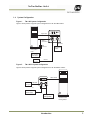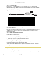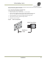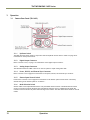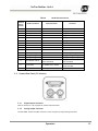
1
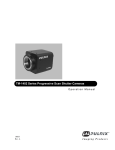
TM-1402 Series
Digital Monochrome/Color
Progressive Scan, Interline-Transfer Camera
Document Version: D
Document P/N: 10053
TM/TMC/RM/RMC-1402 Series
Notice
The material contained in this manual consists of information that is proprietary to JAI, Inc., and may only be
used by the purchasers of the product. JAI, Inc. makes no warranty for the use of its product and assumes no
responsibility for any errors which may appear or for damages resulting from the use of the information
contained herein. JAI, Inc. reserves the right to make changes without notice.
Microsoft, Windows 95, 98, NT, 2000, XP, and Windows Explorer are either registered trademarks or trademarks
of Microsoft Corporation in the United States and/or other countries.
Warranty
Please contact your factory representative for details about the warranty.
Certifications
CE Compliance
The TM-1402 series of cameras has been certified to conform to the requirements of Council Directive
89/336/EC for electromagnetic compatibility and to comply with the following European Standards:
EMC
EN55022: 1998 + A1: 2000 CLASS A
EN55024: 1998 + A1: 2001
All JAI Inc. products bearing the CE mark have been declared to be in conformance with the applicable EEC
Council Directives. However, certain factory-installed options or customer-requested modifications may
compromise electromagnetic compatibility and affect CE compliance. Please note that the use of interconnect
cables that are not properly grounded and shielded may affect CE compliance.
Contact the JAI, Inc. Applications Engineering Department for further information regarding CE compliance.
FCC
This equipment has been tested and found to comply with the limits for a Class A digital device, pursuant to
Part 15 of the FCC Rules. These limits are designed to provide reasonable protection against harmful
interference when the equipment is operated in a commercial environment. This equipment generates, uses
and can radiate radio frequency energy and, if not installed and used in accordance with the instruction
manual, may cause harmful interference to radio communications. Operation of this equipment in a residential
area may cause harmful interference, in which case the user will be required to correct the interference at his
own expense.
WARNING
Changes or modifications to this unit not expressly approved by the party responsible for FCC compliance could
void the user’s authority to operate the equipment.
TM-1402 Series Operation Manual
JAI Inc.
625 River Oaks Parkway
San Jose, CA 95134
Tel:(408) 383-0300
Tel:(800) 445-5444
Fax:(408) 383-0301
Email: [email protected]
www.jai.com
September 22, 2009
Disclaimer
iii
TM/TMC/RM/RMC-1402 Series
iv
Disclaimer
TM/TMC/RM/RMC-1402 Series
Table of Contents
Disclaimer Notice ................................................................................................... iii
Table of Contents ................................................................................................... v
List of Figures ....................................................................................................... vii
List of Tables ......................................................................................................... ix
Introduction............................................................................................. 1 1 1.1 Product Description ................................................................................... 1 1.2 Features ................................................................................................. 1 1.3 Functional Options ..................................................................................... 2 1.4 System Configuration.................................................................................. 3 2 Installation .............................................................................................. 4 2.1 Getting Started ......................................................................................... 4 2.1.1 Unpacking Instructions ................................................................................ 4 2.1.2 Components List ....................................................................................... 4 2.1.3 Accessories and Options .............................................................................. 4 2.2 Camera Setup........................................................................................... 4 2.2.1 Heat Dissipation ........................................................................................ 4 2.2.2 Connector Pin Configurations ........................................................................ 5 2.2.3 Shutter Speed Control Dial (TM-1402 only) ........................................................ 7 2.2.4 RS-232 Communication Cable (TM-1402 only) ..................................................... 7 2.2.5 Digital Output Cable (TM-1402 only) ................................................................ 8 2.2.6 Camera Link Cable (CL Versions Only) .............................................................. 9 2.2.7 Power Supplies and Power Cable Setup ............................................................ 9 2.2.8 Attaching the Analog Video Output ................................................................ 10 2.2.9 Attaching the Camera Lens.......................................................................... 10 2.2.10 Back Focus Adjustment (CL Models Only) ....................................................... 11 3 Operation .............................................................................................. 12 3.1 Camera Rear Panel (TM-1402) ...................................................................... 12 3.1.1 Up/Down Switch ...................................................................................... 12 3.1.2 Digital Output Connector ............................................................................ 12 3.1.3 Analog Output Connector ............................................................................ 12 3.1.4 Power, RS-232, and External Sync Connector .................................................... 12 3.1.5 Shutter Speed Control Switch ....................................................................... 12 3.1.6 Mode Selection Switch ............................................................................... 12 3.2 Camera Rear Panel (CL Versions)................................................................... 13 3.2.1 Digital Output Connector ............................................................................ 13 3.2.2 Analog Output Connector ............................................................................ 13 3.2.3 Power and External Sync Connector ............................................................... 14 3.3 Progressive Scanning ................................................................................. 14 3.4 Electronic Shutter .................................................................................... 14 3.5 Asynchronous Reset................................................................................... 14 3.5.1 External VINIT With Pulse Width ................................................................... 15 3.5.2 Internal Shutter Speed Control ..................................................................... 16 3.6 Programmable Look-Up Table (LUT) and Knee Control ......................................... 16 3.7 Scan Modes ............................................................................................. 17 3.7.1 Full Progressive Scan ................................................................................. 17 3.7.2 Partial Scan ............................................................................................ 17 3.8 External Sync .......................................................................................... 17 3.9 Bayer Color Filter (Color Versions) ................................................................. 17 Table of Contents
v
TM/TMC/RM/RMC-1402 Series
3.9.1 3.9.2 3.9.3 3.9.4 3.9.5 3.9.6 3.9.7 3.10 3.11 Color Filter Array ..................................................................................... 17 Bayer Color Filter Array (CFA) ...................................................................... 18 Starting Pixel Configuration ......................................................................... 18 Sync and Data ......................................................................................... 19 Camera Functions ..................................................................................... 19 Interpolation Software ............................................................................... 20 Color Interpolation ................................................................................... 20 Camera Timing Charts ............................................................................... 21 Serial Communication Kit CS-232C (not required for “CL” version) .......................... 27 4 Troubleshooting ....................................................................................... 28 4.1 Problems and Solutions .............................................................................. 28 4.1.1 Symptom: No Video................................................................................... 28 4.1.2 Symptom: Dark Video ................................................................................ 28 4.1.3 Symptom: Non-Synchronized Video ................................................................ 28 4.2 Information and Support Resources ................................................................ 28 5 Appendix ............................................................................................... 29 5.1 Specifications.......................................................................................... 29 5.2 Physical Dimensions .................................................................................. 30 5.3 Spectral Response .................................................................................... 31 vi
Table of Contents
TM/TMC/RM/RMC-1402 Series
List of Figures
Figure 1. Figure 2. Figure 3. Figure 4. Figure 5. Figure 6. Figure 7. Figure 8. Figure 9. Figure 10. Figure 11. Figure 12. Figure 13. TM-1402 System Configuration....................................................................... 3 TM-1402CL System Configuration.................................................................... 3 12-Pin Connector on Rear Panel of Camera ....................................................... 5 31-Pin Digital Connector on Rear Panel of Camera (TM-1402 only)............................ 5 Serial Communication Cable RS-232B-12 ........................................................... 7 Pinout Configuration for Digital Output Cable .................................................... 8 12P-02S Interface Cable (optional) ................................................................ 10 Back Focus Adjustment .............................................................................. 11 Pulse Width Async Shutter Timing ................................................................. 15 Physical Dimensions (TM-1402) ..................................................................... 30 Physical Dimensions (TM-1402CL) .................................................................. 30 Monochrome Spectral Response .................................................................... 31 Color Spectral Response ............................................................................. 31 List of Figures
vii
TM/TMC/RM/RMC-1402 Series
List of Tables
Table 1 Table 2 Table 3 Table 4 Table 5 Table 6 Table 7 Table 8 viii
12-Pin Connector (TM-1402) ......................................................................... 5 12-Pin Connector (TM-1402CL) ...................................................................... 5 31-Pin Connector (MP211-031-113-4300)........................................................... 6 Connector Pinout Configurations .................................................................... 6 Shutter Speed Control Dial ........................................................................... 7 Mode Selection Switch ............................................................................... 13 External Sync .......................................................................................... 17 TM-1402 Series Product Specifications Table .................................................... 29 List of Tables
TM/TMC/RM/RMC-1402CL
TM-1402 Series Operation Manual
1
Introduction
1.1
Product Description
The JAI, Inc. TM-1402 series consists of high-resolution, high-speed progressive scan CCD cameras.1 The
progressive interline-type CCD permits full vertical and horizontal resolution of very high speed shutter images
and applications. The electronic shutter, which has speeds to 1/16,000 sec., can be reset asynchronously by
external pulse control. Several frame rates are available: 15, 30, 56, 98 fps. On-chip micro lenses provide
increased sensitivity.
The TM-1402 has a full dynamic range control function, which can be set at externally selectable lookup-table
(LUT) knee slopes to convert 10-bit input to 8-bit output, thereby optimizing the CCD’s full dynamic range in
the normal output signal range. The camera has an 8-bit, RS-644 digital signal output for interfacing with
external image-processing systems. All the key functions are externally controlled via RS-232C. The TM-1402CL
model has a Camera Link output and its key functions are externally controlled via differential serial
communication of Camera Link.
Applications for the TM-1402 include machine vision, medical imaging, intelligent transportation systems, highdefinition graphics, on-line inspection, gauging, character reading, archiving, and high security surveillance.
1.2
Features
•
Miniature size and light weight
The printed circuit boards in the TM-1402 have been arranged based on a design philosophy that creates
modular electronics for the camera, giving it flexibility. In addition, the use of miniature solid-state
components results in a compact, lightweight camera that is 44mm x 44mm x 64mm in dimensions, and weighs
only 138 grams.
•
Imager
The TM-1402 uses a progressive scan interline transfer CCD that has the following features:
−
−
−
−
−
−
Resolution of 1392 x 1040 active pixels for excellent image quality.
4.65 x 4.65 μm square pixels for precise dimensional measurement.
High-speed electronic shutter capability for high dynamic resolution of moving objects and electronic
iris control that eliminates the need for a mechanical shutter.
Progressive scan CCD eliminates interlace deterioration of image and increases ease of computer
interface.
High sensitivity and low noise at fast scanning. The CCD can drive faster than 50 MHz pixel clock rate
and has an excellent S/N ratio that is greater than 52dB.
- The CCD for the TM-1402 has built-in microlenses.
1
*. Unless specifically mentioned, all information in this manual is relevant to all cameras in the TM-1402
series, including the TM-1402, TMC-1402, RM-1402, RMC-1402, TM-1402CL, TMC-1402CL, RM-1402CL and RMC1402CL.
Introduction
1
TM/TMC/RM/RMC-1402 Series
•
Electronic shutter
The TM-1402 has a substrate drain-type shutter mechanism which provides superb pictures at various speeds
without smearing. A built-in manual shutter speed control selects the electronic shutter rate of 1/60 (nonasync mode only), 1/125, 1/250, 1/500, 1/1,000, 1/2,000, 1/4,000, 1/8,000, or 1/16,000 second.
With VINIT high (5V), the CCD keeps discharging. With a negative pulse to VINIT, the camera resets and purges
the charge momentarily. Then it starts integrating for the period of shutter control set by either an external
pulse width or internal shutter control. Progressive scanning permits a full 1040 lines of vertical resolution, as
compared to a conventional CCD camera which captures only half the vertical lines per shutter.
•
Asynchronous reset (VINIT)
The TM-1402’s asynchronous reset is flexible and accepts external horizontal drive (HD) for phase locking.
When the VINIT pulse is applied, it resets the camera's scanning and purging of the CCD. There are two modes
to control the asynchronous reset and shutter speed:
−
External VINIT with pulse width. The duration between pulse edges controls the shutter speed
externally.
− Internal shutter control mode. The speed control varies from 1/125 to 1/16,000 sec. The video signal
starts with internal V reset timing related to shutter speed.
•
Output
The TM-1402 has an 8-bit RS-644 (LVDS) digital output for interfacing with external image processing systems.
The TM-1402 camera is also available with RS-422 digital output as an option (OP-93). The TM-1402CL has a
Camera Link output. The analog output is 1.0 Vp-p composite video (75 Ω).
•
Asynchronous image capturing
The TM-1402 captures async reset images and provides single-shot video output with single FDV.This makes it
simpler for an ordinary frame grabber to capture the async reset images.
•
Warranty
The CCD solid-state image sensor allows the camera to maintain a superior performance level indefinitely while
requiring virtually no maintenance. Please contact your factory representative for details about the warranty.
Warning: Unscrewing the camera cover or opening the camera in any way will void the
warranty unless prior written approval is obtained from the factory.
1.3
Functional Options
•
•
2
RS-422 (digital) output (OP93) (TM-1402).
10-bit output (OP93-1).
Introduction
TM/TMC/RM/RMC-1402CL
System Configuration
Figure 1.
TM-1402 System Configuration
Figure 1 below presents a typical system configuration for the TM-1402 camera.
CDE
AB
3 45 6
23
45
Digital cable
UP
F0 1
2
8
67 9
01
78 9
1.4
SHUTTER MODE
DOWN
DIGITAL
1 9
2
3
RS-232B-12
cable in
CS-232E kit
11
4
8
10
7
12
5
6
POWER
VIDEO
BNC cable
12-pin
connectors
analog frame
grabber
Computer with
frame-grabber
board
PD-12 (series)
power supply
OR
12P-02S
Power and
Ext. Sync
Figure 2.
TM-1402CL System Configuration
Figure 2 below presents a typical system configuration for the TM-1402CL camera.
26CL-02-26
CAMERA LINK
Power and
Ext. Sync
12P-02S
POWER
VIDEO
or
PD-12P (series)
power supply
Analog
frame grabber
Introduction
Computer with
Camera Link™
frame grabber
3
TM/TMC/RM/RMC-1402 Series
2
Installation
The following instructions are provided to help you to set up your camera quickly and easily. We suggest that
you read through these instructions before you unpack and set up your camera system.
2.1
Getting Started
2.1.1
Unpacking Instructions
We recommend that you save the original packing cartons for the cameras and accessories in case you need to
return or exchange an item.
We also recommend that you bench-test any equipment being sent to another location for field installation to
assure that everything is fully operational as a system.
2.1.2
Components List
Please begin by checking your order against the Components List shown below to assure that you have received
everything as ordered, and that nothing has been overlooked in the packing materials. If any item is missing,
please contact your JAI, Inc. representative immediately.
•
•
TM-1402 camera
Document download card (includes instructions on how to download the necessary documentation and
software)
2.1.3
Accessories and Options
Following is a list of additional accessories and options that may be required for your application. Please check
with your JAI, Inc. representative before you install your camera to determine what you might need.
•
−
−
•
Note:
•
•
•
2.2
Digital output cable (not required for “CL” version)
30DG-02 (for standard model only)
26CL-02-26 (for Camera Link model only)
Serial Communication Kit CS-232E (not required for “CL” version)
For CL models, the control software is downloadable. Serial communication is through the Camera Link
cable. No additional accessories are required.
PD-12UUP series power supply (see Section 2.2.6 on page 11)
12P-02S power cable
Tripod Mounting Kit: TP-20
(for dimensions go to: www.jai.com/EN/CameraSolutions/Products/Accessories/Pages/Home.aspx)
Camera Setup
2.2.1
Heat Dissipation
The TM-1402 camera is a compact 1.4 megapixel camera. Since all the electronics have been packed in a very
small package, the outer case of the camera gets hot due to heat dissipation. JAI. Recommends using a cooling
fan to set up a positive air flow around the camera, and following the precautions below:
•
•
•
4
Mount the camera on a large heat sink (camera bracket) made out of a conductive material such as
aluminum.
Make sure the flow of heat from the camera case to the bracket is not blocked by a non-conducting
material like plastic.
Make sure the camera has enough open space around it to facilitate the free flow of air.
Installation
TM/TMC/RM/RMC-1402CL
2.2.2
Connector Pin Configurations
1
2.2.2 (a) 12-Pin Connector (TM-1402)
Figure 3.
2
3
12-Pin Connector on Rear Panel of Camera
Table 1
11
4
The TM-1402 has a 12-pin Hirose connector for power input,
serial communication, and signal integration. Pin #1 is Ground
and Pin #2 is +12V DC. Other pins handle a number of input
and output functions, as shown in Table 1 below.
9
8
10
7
12
5
6
12-Pin Connector (TM-1402)
Pin
Description
Pin
Description
1
GND (power)
7
VD In
2
+12V DC
8
Reserved
3
GND (analog)
9
HD In
4
Video Out
10
RXD (RS-232)
5
GND (digital)
11
N/C
6
VINIT In
12
TXD (RS-232)
2.2.2 (b) 12-Pin Connector (TM-1402CL)
The TM-1402CL has a 12-pin Hirose connector for power input and signal integration. Pin #1 is Ground and pin
#2 is +12V DC. The pinout table is shown below. For the TM-1402CL, serial communication camera control is
done via the MDR26 Camera Link connector on the rear panel of the camera.
Table 2
12-Pin Connector (TM-1402CL)
Pin
Description
Pin
Description
1
GND (power)
7
VD in
2
+12V DC
8
Reserved
3
GND (analog)
9
HD in
4
Video out
10
N/C
5
GND (digital)
11
N/C
6
N/C
12
N/C
2.2.2 (c) Digital Output Connector (TM-1402 only)
The TM-1402 has a 31-pin AirBorn connector (MP211-031-113-4300) on the rear panel to output 8-bit, RS-644
video data. The connector pin-out is shown in the figure below.
Figure 4.
31-Pin Digital Connector on Rear Panel of Camera (TM-1402 only)
1
16
17
31
Note:
CLK: data clock, LDV: Line Data Valid, FDV: Frame Data Valid, INTEG: Integration control, EXT CLK:
external pixel clock, []: Differential input option.
Installation
5
TM/TMC/RM/RMC-1402 Series
Table 3
31-Pin Connector (MP211-031-113-4300)
Pin #
Description
I/O
Pin #
Description
I/O
1
CLK+
Out
17
CLK-
Out
2
LDV+
Out
18
LDV-
Out
3
FDV+
Out
19
FDV-
Out
20
VINIT (TTL)
N/C
In
4
GND
5
EXT HD
(TTL)
[EXT CLK+]
In
21
EXT VD
(TTL)
[EXT CLK-]
In
6
N/C
[HD+]
In In
22
N/C
[HD-]
In
7
N/C
[VINIT+/(VD+)]
In
23
GND
[VINIT-/(VD-)]
In
8
D0+
Out
24
D0-
Out
9
D1+
Out
25
D1-
Out
10
D2+
Out
26
D2-
Out
11
D3+
Out
27
D3-
Out
12
D4+
Out
28
D4-
Out
13
D5+
Out
29
D5-
Out
14
D6+
Out
30
D6-
Out
15
D7+
Out
31
D7-
Out
16
GND
2.2.2 (d) Camera Link Connector
The TM-1402CL has a 26-pin connector on the rear panel to output Camera Link data. The connector pin-out is
shown in Table 4 below.
13
1
26
Table 4
14
Connector Pinout Configurations
Camera Link Connector
Pin #
6
Description
I/O
Pin #
Description
I/O
1
GND
14
GND
(Shield)
2
Tx OUT 0-
Out
15
Tx OUT 0+
Out
3
Tx OUT 1-
Out
16
Tx OUT 1+
Out
4
Tx OUT 2-
Out
17
Tx OUT 2+
Out
5
Tx CLK OUT-
Out
18
Tx CLK OUT+
Out
6
Tx OUT 3-
Out
19
Tx OUT 3+
Out
7
SerTC+
In
20
SerTC-
In
8
SerTFG-
Out
21
SerTFG+
Out
9
VINIT- (CC1-)
In
22
VINIT+ (CC1+)
In
10
INTEG+ (CC2+)
In
23
INTEG- (CC2)
In
11
N/C
In
24
N/C
In
Installation
TM/TMC/RM/RMC-1402CL
Note:
Pin #
Description
I/O
Pin #
Description
I/O
12
N/C
In
25
N/C
In
13
GND
26
GND
SerTC: Differential Serial Communication to camera; SerToFG: Differential Serial Communication to
frame grabber.
2.2.2 (e) Analog Output Connector
The TM-1402 has a BNC connector on the rear panel
to output non-standard analog video.
2.2.3
Shutter Speed Control Dial (TM-1402 only)
8
7
Shutter speed can be selected by switching the shutter dial
to the appropriate setting (0 through 9). The factory default
settings correspond to the shutter speeds as shown in below.
Table 5
9 0 1
2
3
6 5 4
Shutter Speed Control Dial
Shutter Exposure Time (Seconds)
Normal
Async
no shutter (1/30)
no shutter (1/30)
1
1/60
1/16,000
2
1/125
1/8,000
3
1/250
1/4,000
4
1/500
1/2,000
5
1/1,000
1/1,000
6
1/2,000
1/500
7
1/4,000
1/250
8
1/8,000
1/125
9
1/16,000
Ext. pulse width control
0
2.2.4
RS-232 Communication Cable (TM-1402 only)
Figure 5.
Serial Communication Cable RS-232B-12
2000±20mm
40±3mm
1925±10mm
Receptacle
75mm±5mm
1
6
5
9
Jack
190±5mm
The RS-232 controller set CS-232E includes cable RS-232B-12 interface cable, software disk, and a quick-start
card. The TM-1402 camera’s built-in look-up table (LUT) can be controlled by an external RS-232 interface. The
camera settings can be programmed or changed using the communication cable and software. Commands from
the RS-232 interface will override the rear panel switch settings of the camera. Please refer to the AccuPiXEL
Series Camera-Control Software manual for details on the graphical user interface.
Installation
7
TM/TMC/RM/RMC-1402 Series
2.2.5
Digital Output Cable (TM-1402 only)
Male
Female
17
1
31
16
25.0mm
1.00 in
20
1
37
19
78.74 in (2 meters)
The TM-1402 camera uses the cable 30DG-02 from JAI, Inc. as a digital output cable. This cable has a 31-pin
AirBorn connector on the camera end and a 37-pin D-sub male connector on the other end. Contact your JAI,
Inc. representative regarding availability of interface cables for specific frame grabber models. Pinout
configuration for the digital cable is shown below.
Figure 6.
FROM 31 PIN CONN.
8
Pinout Configuration for Digital Output Cable
TO 37 PIN CONN
WIRE COLOR
FROM 31 PIN CONN
TO 37 PIN CONN
WIRE COLOR
PIN 1
CLK+
PIN 1
CLK+
ORG
1RED
PIN 19
FDV-
PIN 22
FDV-
WHT
1BLU
PIN 2
LDV+
PIN 2
LDV+
GRY
1RED
PIN 20
VINIT
PIN 17
VINIT
YLW
1BLU
PIN 3
FDV+
PIN 3
FDV+
WHT
1RED
PIN 21
VD
PNK
1BLU
PIN 4
GND
PIN 16
GND
YLW
1RED
PIN 22
NC
PIN 18
NC
ORG
2BLU
PIN 5
HD
PNK
1RED
PIN 23
GND
PIN 23
GND
GRY
2BLU
PIN 6
INTEG
PIN 37
INTEG
ORG
2RED
PIN 24
D0-
PIN 27
D0-
WHT
2BLU
PIN 7
NC
GRY
2RED
PIN 25
D1-
PIN 28
D1-
YLW
2BLU
PIN 8
D0+
PIN 8
DO+
WHT
2RED
PIN 26
D2-
PIN 29
D2-
PNK
2BLU
PIN 9
D1+
PIN 9
D1+
YLW
2RED
PIN 27
D3-
PIN 30
D3-
ORG
3BLU
PIN 10
D2+
PIN 10
D2+
PNK
2RED
PIN 28
D4-
PIN 31
D4-
GRY
3BLU
PIN 11
D3+
PIN 11
D3+
ORG
3RED
PIN 29
D5-
PIN 32
D5-
WHT
3BLU
PIN 12
D4+
PIN 12
D4+
GRY
3RED
PIN 30
D6-
PIN 33
D6-
YLW
3BLU
PIN 13
D5+
PIN 13
D5+
WHT
3RED
PIN 31
D7-
PIN 34
D7-
PNK
3BLU
PIN 14
D6+
PIN 14
D6+
YLW
3RED
PIN 15
D7+
PIN 15
D7+
PNK
3RED
PIN 35
GND
SHIELD
PIN 16
NC
NC
PINS 4, 5, 6, 7, 19,
24, 25, 26, AND 36
NC
PIN 17
CLK-
PIN 20
CLK-
ORG
1BLU
PIN 18
CDV-
PIN 21
LDV-
GRY
1BLU
Installation
TM/TMC/RM/RMC-1402CL
2.2.6
Camera Link Cable (CL Versions Only)
The MDR26 cable assembly (26CL-02-26) from 3M (part number 10226-6212VC) has been standardized as the
Camera Link cable. This cable has the 26-pin MDR26 connector on both ends. This is a straight-through cable.
The pin-out configuration is shown in Table 4 on page 8.
Note:
For TM-1402CL, serial communication for camera control is done via the Camera Link connector on the
rear panel of the camera.
Cable assemblies and boardmount receptacles can be ordered from 3M.
2.2.7
Power Supplies and Power Cable Setup
2.2.7 (a) Power Supplies
The TM-1402 requires 12V DC power that is obtained through the 12-pin connector located on the rear panel of
the camera. JAI, Inc. recommends the following power supplies:
PD-12UU
100-240V AC/12V DC
(No 12-pin connector)
1.2A universal voltage power supply with US plug
PD-12UUP
100-240V AC
1.2A universal voltage power supply with US plug
and 12-pin connector
PD-12UE
100-240V AC/12V DC
1.2A universal power supply with European plug
(No 12-pin connector)
PD-12UEP
100-240V AC/12V DC
1.2A universal power supply with European plug and
12-pin connector
If you are providing power through the 12-pin connector, the PD-12UUP and PD-12UEP power supplies are
available with the 12-pin mating connector already attached to the leads from the power supply. The PD-12UU
or PD-12UE power supply can be connected to the JAI, Inc. power cable either directly or via a terminal strip.
When wiring the PD-12UU power supply directly, please note the following:
•
The lead ends must be twisted together and tin-soldered for strength and electrical continuity.
•
Shrink tubing or a similar insulator should be used to prevent exposed leads from touching and shorting.
•
The +12V lead is marked with a red stripe or white lettering; be sure not to reverse the leads.
•
All connections must be properly insulated to prevent shorting.
Installation
9
TM/TMC/RM/RMC-1402 Series
2.2.7 (b) JAI, Inc. Power Cables
If you are using JAI, Inc. power cables such as the 12P-02S, please refer to the 12-pin connector pin-out
diagram in “12-Pin Connector (TM-1402)” on page 6. The cable pin-out diagram is shown in Figure 7 below. The
color-coded leads use Gray for Ground and Yellow for +12V.
Figure 7.
12P-02S Interface Cable (optional)
+12 V
GND (Gray)
Power (Yellow)
Video Out (Red Coax)
HD In (White Coax)
VD In (Black Coax)
Jack
}
Analog
Frame Grabber
12P-02S Interface Cable
Pin#
Lead Color
Function
Pin#
Lead Color
Function
1
Gray
GND
7
Black coax
VD Input
2
Yellow
+12V DC
8
White coax shield
Reserved
3
Red coax shield
GND
9
White coax
HD Input
4
Red coax
Video
10
Brown
RXD
5
Orange coax shield
GND
11
Blue
Integration
6
Orange coax
VINIT IN
12
Black coax shield
TXD
Note: Make sure that the unused leads are not touching and that there is no possibility that exposed wires
could cause the leads to short.
2.2.7 (c) Building Your Own Power Cable
Refer to the 12-pin connector pin-out in Section 2.2.2 (a on page 6. Connect the Ground lead to pin #1, and the
+12V DC lead to pin #2 of the 12-pin connector. Power must be DC-regulated, and of sufficient current to
properly power the camera.
2.2.7 (d) Attaching the Power Cable to the Connector
The 12-pin connector is keyed and will only fit in one orientation. Follow these directions to properly attach
the power cable to the camera connector:
1.
Rotate the connector while applying slight pressure until the keyways line up.
2.
Press the connector into place until firmly seated.
3.
Plug the power cord into the AC socket. This will power the camera up.
2.2.8
Attaching the Analog Video Output
When connecting the TM-1402 to an analog frame grabber or a multisync monitor, use the BNC connector on
the rear panel of the camera. The input of the monitor should be balanced for 75Ω termination. Standard RG59 type coaxial cable should carry a full video signal for up to 100 feet.
The multi-conductor cable 12P-02S from JAI, Inc. can be used to transmit analog video, power, sync. signals,
and serial communication. The mini coaxial leads in JAI, Inc. multi-conductor cables are designed for short runs
of no longer than 100 feet.
Note:
Make sure that no extraneous wires are visible which could cause a short.
2.2.9
Attaching the Camera Lens
The TM-1402 camera accepts 1/2" or larger format size C-mount lenses. To attach the C-mount lens to the
camera, carefully engage the threads and rotate the lens clockwise until it firmly seats on the mounting ring.
10
Installation
TM/TMC/RM/RMC-1402CL
Do not force the lens if it does not seat properly. Please note that some lenses with extremely long flangebacks
may exceed the mounting depth of the camera.
2.2.10
Back Focus Adjustment (CL Models Only)
To adjust the back focus, follow the steps below:
1.
Mount the manual lens (e.g. Cosmicar 25mm, F=1.4) on the camera.
2.
Open the lens iris completely and set lens focal length to minimum for the lens used
(e.g. 2 ft.). If the image is not focused properly, set the back focus as follows.
3.
Unscrew the M2x3 hex screw on the Front Panel until the focus ring is loose.
4.
Adjust the silver back focus ring until the image is focused.
5.
Repeat steps 3 and 4 as needed.
Figure 8.
Back Focus Adjustment
Back Focus Ring
Backfocus
2 feet
Installation
11
TM/TMC/RM/RMC-1402 Series
3
Operation
3.1
Camera Rear Panel (TM-1402)
3.1.1
Up/Down Switch
The Mode Selection switch works in conjunction with the Up/Down switch. Refer to Table 6 on page 15 for
information on the Up/Down switch.
3.1.2
Digital Output Connector
Refer to Section 2.2.2 (c on page 7 for information on the digital output connector.
3.1.3
Analog Output Connector
The TM-1402 camera has a BNC connector on the rear panel to output analog video data.
3.1.4
Power, RS-232, and External Sync Connector
Refer to Section 2.2.2 on page 6 for information on the power, RS-232, and external sync connector.
3.1.5
Shutter Speed Control Switch
Please refer to Section 2.2.3 on page 9 for information on the Shutter Speed Control switch. The factory
default setting to the shutter speeds is “no shutter.”
3.1.6
Mode Selection Switch
Various modes can be implemented with the rear panel Mode Selection switch. The Mode Selection switch
works in conjunction with the Up/Down switch and RS-232 external control. Commands from the RS-232
interface will override the rear panel switch settings of the camera. The table below shows details on various
modes.
12
Operation
TM/TMC/RM/RMC-1402CL
Table 6
Mode
Selection
Switch
Position
Up/Down Switch
Functions
0
Switch Disabled
Switch Disabled
None
1
Set Gain
Up / Down
Change gain
2
Set Vtop (A/D)
Up / Down
Change A/D ref. top
3
Set Vbottom (A/D)
Up / Down
Change A/D ref. bottom
4
Gain Selection #1
Up: 9dB, Down: 12dB
Lower gain selection
5
Gain Selection #2
Up: 18dB, Down: 22dB
Higher gain selection
6
Linear LUT
Up
Back to linear table
7
Knee Selection
Up / Down (Scroll)
Scroll 8 different LUTs
8
Async Reset Mode
Up: Normal, Down: Async
Async and normal shutter
9
Factory Default Recall
Up / Down: Recall
Factory setting
A
3.2
Mode Information
Mode Selection Switch
Up: Recall, Down: Save
Power up page setting
B
User Page Storage #1
Power Up Setting
Up: Recall, Down: Save
User page storage setting
C
User Page Storage #2
Up: Recall, Down: Save
User page storage setting
D
Direct Shutter Control
Up: Increment
Down: Decrement
Change Direct shutter speed
in 1H increments
E
Scan Format2
Up: PS500L Down: PS250L
Partial Scan 500L
Partial scan 250L
F
Scan Format1
Up: 30fps, Down: 15fps
30 fps, 15 fps
Camera Rear Panel (CL Versions)
3.2.1
Digital Output Connector
Refer to Section 2.2.2 (d on page 8 for Camera Link information.
3.2.2
Analog Output Connector
The TM-1402CL camera has a BNC connector on the rear panel to output analog video data.
Operation
13
TM/TMC/RM/RMC-1402 Series
3.2.3
Power and External Sync Connector
Refer to Table 2 on page 6 for information on the power and external sync. connectors.
3.3
Progressive Scanning
Standard TV-system scanning is 525 lines interlace scanning as specified in the RS-170 protocol. Every other
horizontal line (odd lines and even lines) is scanned at a 60Hz rate per field, and the scanning is completed
with two fields (one frame) at 30Hz rate. Because of the interlace scanning, the vertical resolution of CCD
cameras is limited at 350 TV lines, regardless of the horizontal resolution. When electronic shutter is applied,
the CCD can hold only one field of charge at each exposure. Therefore, the vertical resolution of the
electronic-shutter camera is only 244 TV lines. The situation is the same for an HDTV-format camera, since it
has interlaced scanning and the vertical resolution of the shuttered image is 500 lines.
The TM-1402 uses a state-of-the-art progressive scanning interline transfer CCD which scans all lines
sequentially from top to bottom at one frame rate (30Hz). Like a non-interlace computer screen, it generates a
stable, crisp image without alternating lines and provides full vertical TV resolution of 1040 lines (a normal TV
monitor display may not be able to show images due to monitor scanning).
The interline transfer architecture is also important to generate simultaneous shuttering. This is different from
full frame transfer architecture which requires a mechanical shutter or strobe light in order to freeze the
object motion.
The TM-1402 outputs the progressive scan image with an electronic shutter in two different formats:
•
Progressive scanning digital and analog output
The CCD signal goes through A/D and D/A converters and through 10-bit in, 8-bit out look-up table (LUT).
The digital output is available from 31-pin connector with RS-644 format (50MHz clock rate).
The analog output is the same as 75Ω, 1Vp-p format at 30Hz rate available from BNC and 12-pin
connector.
•
Partial scan output (display output)
− Partial scan: 500 lines at 56 frames per second.
− Partial scan: 250 lines at 98 frames per second.
Note: Minimal blooming may occur under partial scanning mode due to the nature of the CCD.
3.4
Electronic Shutter
For more information about the electronic shutter, please see Section 1.2 on page 2.
3.5
Asynchronous Reset
For more information about Asynchronous Reset, please see Section 1.2 on page 2.
14
Operation
TM/TMC/RM/RMC-1402CL
3.5.1
External VINIT With Pulse Width
The TM-1402 can be reset with external reset pulse (VINIT). Set the dial switch to “9”. Apply a pulsewidth
control VINIT signal generated from an external event trigger to the camera. The internal reset pulse will be
latched to HD and at the first HD timing from the external pulse leading edge (negative going edge). The CCD
discharge pulse will be generated to clear the images. The internal VD will be generated at the following edge
(positive going edge) of the external pulse, resetting the internal timing including the video sync. The shutter
speed is the same as the external pulse width, but the integration delays 1H from the leading edge. For the
immediate reset option, please contact JAI, Inc.
For the progressive format, one frame of video output will start from the rising edge of the pulse width control.
In async mode with external pulse input high, the video output will be disabled as the camera continues
discharging the CCD image, providing black video only.
Figure 9.
Pulse Width Async Shutter Timing
No-Delay Shutter
EXT. VINIT (Pulse width control)
HD
INT. VD after trailing edge of EXT. VINIT
Discharge
Exposure time set by pulse width
Transfer Gate
13H
FDV
Vsync
Analog Video Sync
Operation
15
TM/TMC/RM/RMC-1402 Series
3.5.2
Internal Shutter Speed Control
The video signal starts with internal VD. The camera operates the reset and shutter in the same way as the
external pulse width control mode. When the external VINIT pulse is applied, internal VD is latched to HD and
the internal VD is delayed to set up the shutter speed period. The shutter speed is controlled by the dial switch
from “1” to “8.” Video output timing starts right after the internal VD and single shots, FDV is output at the
internal VD timing.
3.6
Programmable Look-Up Table (LUT) and Knee Control
The TM-1402 has a built-in LUT (look-up table) for dynamic range control.
At a specific gain setting, the offset (minimum level.... dark point) and A/D reference top voltage (maximum
level... saturation point) are set to 10-bit A/D input so that the full dynamic range of the CCD is utilized at 10bit references as the input and the LUT output is converted into 8-bit to adjust the gamma correction.
The 10-bit input is segmented into two or more regions by the knee-point settings as variable gamma selection.
LUT selections: (a standard LUT is 10 sets of knee-control LUT)
16
•
Variable Gamma
•
Variable knee curve
•
Direct input LUT
Operation
TM/TMC/RM/RMC-1402CL
3.7
Scan Modes
The TM-1402 supports the following scan modes:
3.7.1
Full Progressive Scan
The normal scan mode progressively scans a full frame of 1392 x 1040 pixels at 15/30 frames per second using
the standard 25MHz/50MHz pixel clock and a single channel output. In contrast to interlace-scan cameras, all
of the 1040 lines in the frame are exposed simultaneously per image capture.
3.7.2
Partial Scan
Partial scan is a standard feature in the TM-1402. The TM-1402 has two types of partial scan modes: 500 and
250 lines. Both modes can be selected through software control. The video image in partial scan mode is the
center 500 or 250 lines of video. The maximum frame rate at 500 lines is 56 fps. The maximum frame rate at
250 lines is 98 fps.
3.8
External Sync
The TM-1402 accepts an external sync of standard HD and VD at TTL level for general locking to a system sync
and clock. The external sync frequency requirement is as follows:
Table 7
External Sync
30 FPS
15 FPS
fHD = 31.1 KHz ±2%
fHD=15.55 KHz±2%
fVD = 29.53 Hz ± 2%
fVD=14.8 Hz±2% for 15 fps
Pixel clock = 50.00 MHz
3.9
Pixel clock = 25.00 MHz
Bayer Color Filter (Color Versions)
JAI, Inc. AccuPiXEL series color cameras are high-resolution, high-speed progressive scan CCD cameras. The
interline transfer, progressive scan CCD permits full vertical and horizontal resolution of images acquired at
very high shutter speeds. The electronic shutter, which has speeds to 1/16,000 sec., can be reset
asynchronously by external pulse control. Uniform square pixels provide superior image definition in any
orientation. On-chip micro lenses mean increased sensitivity.
3.9.1
Color Filter Array
JAI, Inc. AccuPiXEL cameras use Bayer CFA (color filter array) as their standard primary color filter. This filter
provides the most popular color interpolation supported by numerous software suppliers. The digital format,
either Camera Link or RS-644, allows the camera to output accurate pixel data, including the color information.
When the data is stored in the frame buffer of a frame grabber or computer, the color information is easily
manipulated to restore the original color images. Because the color filter array contains only a single R, G or B
color in each pixel, the restored image has to fill in colors in the missing pixel locations. The software uses
neighboring pixel information to “guess” the missing colors to make smooth, clear images. This is called “color
interpolation.” Today's high-speed computers allow such color interpolation to be done almost in real time.
Operation
17
TM/TMC/RM/RMC-1402 Series
Because these cameras do not contain internal color-processing circuitry, they are smaller and less expensive
than full-function color cameras.
3.9.2
Bayer Color Filter Array (CFA)
The Bayer CFA is an R, G, B primary color filter array. This is the most widely accepted CFA for the single-chip
CCD progressive scan format. This type of array layout has a specific order for each color’s pixels. Since the
human eye’s resolution and color recognition are highest at green, the CFA contains two greens per each red
and blue.
It is critical for the frame grabber and color interpolation to know where the individual color pixels exist
relative to sync (LDV and FDV) timing.
This requirement makes digital output the preferred choice, because the timing relationships are very
accurate.
3.9.3
Starting Pixel Configuration
All manufacturers produce identical Bayer CFAs, but there are slight differences between the CCDs produced by
different manufacturers. The first line is generally R and G. The Sony CCD starts with R. The camera timing can
be adjusted to start with either G or R by skipping the very first pixels at each lines. The majority of color
interpolation software can select between a variety of pixel relations, such as R/G start or G/R start, as well
as G/B start and B/G start. Once the correct scanning is configured, the rest of the interpolation will be
exactly the same. Please contact JAI. Inc. for further information regarding CCD manufacturers.
18
Operation
TM/TMC/RM/RMC-1402CL
3.9.4
Sync and Data
The individual color data is exactly the same as the pixel data. This means that the timing relationships of the
color cameras are also the same as of the B/W cameras. For a detailed timing chart, please refer to each B/W
camera’s data sheet and manual.
If the frame grabber has a standard B/W configuration file, then AccuPiXEL color cameras can use that
configuration file to operate. The configuration file may vary, depending on whether the output is standard
(RS-644) or Camera Link. Please consult JAI, Inc., or your frame grabber supplier for compatibility information.
The following diagram is an example of the TMC-1402 (same as TM-1402).
It is important to meet the exact starting pixel at LDV and the starting line of FDV. If the starting pixel or line
is shifted due to the image capture configuration, then the interpolation software can be adjusted for the
correct starting point. In figure A, if the first pixel is shifted (missed), the color interpolation should start with
G-R. If the first line is missed in A, the interpolation order will be B-G.
3.9.5
Camera Functions
AccuPiXEL color cameras perform all functions the same way as B/W cameras. However, because of color
characteristics, the following issues are different:
•
LUT (Look-up Table)
LUT is a powerful tool to adjust the dynamic range as well as color dynamic range. Since human color
perception is non-linear, LUT selection can help optimize color contrast by selecting the LUT value. Gamma
0.45 is logarithmic and is closed to human perception.
When LUT is selected, black-level adjustment must be more accurate than for B/W cameras.
For a detailed timing chart, please refer to the standard AccuPiXEL camera data sheet, or contact JAI, Inc.
Operation
19
TM/TMC/RM/RMC-1402 Series
3.9.6
Interpolation Software
The color interpolation can be performed in the frame grabber or by using the host computer’s CPU. Most
major frame grabbers with processing capability provide tools for color interpolation. Software vision packages
also provide color interpolation capability, but speed and performance may be determined by the PC’s
resources and by the complexity of the interpolation routine.
3.9.7
Color Interpolation
The Bayer pattern color filter array (CFA) consists of R, G, and B primary colors. Each pixel represents one of
three colors. In order to display or print color images, the signal has to be converted to RGB output, which has
three independent channels (outputs) and sync signals.
Color interpolation software or firmware performs the color preprocessing by
filling the missing color pixels with neighboring pixels. It then separates the
stream of data, (8-bit or 10-bit) into 3 (RGB) data (8-bit x 3) and adds the
color matrix to adjust and balance each of the R,G, and B channels (white
balance or color balance).
The image quality depends on the camera’s own pixel data (including pixel
data independency from neighboring pixels, noise and color filter), and
interpolation of the software algorithm such as 3 x 3 interpolation, 2 x 2
interpolation, color matrix, white balance capability, etc.
All AccuPiXEL color cameras are carefully designed for maximum color performance. JAI, Inc. strongly suggests
that you use digital output for the best performance.
Some software is used on board (FPGA or DSP) to perform the interpolation. Other software simply uses the
host computer’s memory and CPU. The process speed may vary depending on the architecture and speed of the
computer.
20
Operation
TM/TMC/RM/RMC-1402CL
3.10 Camera Timing Charts
Model: TM-1402
Operation Mode: 30 Frame /sec
Master Clock: 100 MHz, M=10 nsec
Pixel Clock: 50 MHz, P= 20 nsec
ec
1. Pixel Clock and Digital Data
Pixel Clock
A
Data
Tcd
TdcT
hd
Tcd: Clock to Data Ready
Tdc: Data Ready to Next Clock
Thd: Data Hold Time
Tcc =14 nsec, Tdc = 6 nsec, Thd = 5 nsec.
2. Horizontal Signals
fHD = [ 31.09KHz]
tHD = [ 32.16 µs]
External HD
[ 3 P], (60 ns)
A [ 1447 P], (28.94 µs)
Internal HD
B [ 1608 P], (32.16 µs)
C [12 P], (240 µs)
D [ 216 P], (4.32 µs)
E [ 1392 P], (27.84 µs)
LDV
F [ 1608 P], (32.16µs)
Digital Data
G [ 1392 P], (27.84 µs)
H [ 216 P], (4.32 µs)
Analog Video
K [ 1392 P], (27.84 µs)
I [ 48 P], (960 ns)
L [ 61 P], (1.22µs)
J [ 168P], ( 3.36 µs)
Operation
21
TM/TMC/RM/RMC-1402 Series
CAMERA TIMING CHARTS
Model: TM-1402
Operation Mode: 30 Frames/Second
Master Clock: 100.00MHz, M = 10 nsec
Pixel Clock:
50 MHz, P = 20 nsec
Horizontal Frequency: 31.09KHz
1H = 32.16 usec
3. External Reset Timing
External VD
A [1053 H], (33.86 msec)
B [1 H], (32.16 us)
C [9 H], (289.44 us)
Internal VD
D [1044 H], (33.58 ms)
E [ 1053 H], (33.86 ms)
F [13 H], (418.08 us)
FDV
G [1040 H], (33.45 ms)
Digital Data
H [13 H], (418.08 us)
I [1040 H], (33.45 ms)
Analog Video
J [10 H], (321.60 us)
K [3 H], (96.48 us)
M [1040 H], (33.45 ms)
L [3 H], (96.48µs)
4. Async Shutter Reset Timing
VINIT Trigger
N [Variable H],(µs)
Internal VD
O [9 H], (289.44 us)
P [1044 H], (33.58 ms)
R [1 H], (32.16 us)
Q [ 1053 H], (33.86 ms)
S [13 H], (418.08 us)
FDV
T [13 H], (418.08 us)
Digital Data
U [1040 H], (33.45 ms)
V [9 H], (289.44 us)
Analog Video
X [1040 H], (33.45 ms)
W [3 H], (96.48µs)
22
Operation
TM/TMC/RM/RMC-1402CL
CAMERA TIMING CHARTS
Model: TM-1402
Operation Mode: 15 Frame /sec
Master Clock: 50 MHz, M= 20 nsec
Pixel Clock: 25 MHz, P= 40 nsec
1. Pixel Clock and Digital Data
Pixel Clock
A
Data
Tcd
TdcT
hd
Tcd: Clock to Data Ready
Tdc: Data Ready to Next Clock
Thd: Data Hold Time
Tcd = 28 nsec, Tdc = 12 nsec, Thd = 10 nsec.
2. Horizontal Signals
fHD = [ 15.55 KHz]
tHD = [ 64.32 µsec]
External HD
[ 3 P], (120 ns)
A [ 1447 P], (57.88 µs)
Internal HD
B [ 1608 P], (64.32 µs)
C [12 P], (480 ns)
D [ 216 P], (8.64 µs)
E [ 1392 P], (55.68 µs)
LDV
F [ 1608 P], (64.32 µs)
Digital Data
G [ 1392 P], (55.68 µs)
H [ 216 P], (8.64 µs)
Analog Video
I [ 48 P], (1.92 µs)
K [ 1392 P], (55.68 µs)
L [ 61 P], (2.44 µs)
J [ 168 P], (6.72 µs)
Operation
23
TM/TMC/RM/RMC-1402 Series
CAMERA TIMING CHARTS
Model: TM-1402
Operation Mode: 15 Frames/Second
Master Clock: 100.00 MHz, M = 10 nsec
Pixel Clock:
25 MHz, P = 40 nsec
Horizontal Frequency: 15.55 KHz
1H = 64.32 usec
3. External Reset Timing
External VD
A [1053 H], (67.73 ms)
B [1 H], (64.32 us)
C [9 H], (578.88 us)
Internal VD
D [1044 H], (67.15 ms)
E [ 1053 H], (67.73 ms)
F [13 H], (836.16 us)
FDV
G [1040 H], (66.89 ms)
Digital Data
H [13 H], (836.16 us)
I [1040 H], (66.89 ms)
J [10 H], (643.20 us)
Analog Video
K [3 H], (192.96 us)
M [1040 H], (66.89 ms)
L [3 H], (192.96 µs)
4. Async Shutter Reset Timing
VINIT Trigger
N [Variable H], (µs)
Internal VD
O [9 H], (578.88 us)
P [1044 H], (67.15 ms)
R [1 H], (64.32 us)
FDV
Q [ 1053 H], (67.73 ms)
S [13 H], (836.16 us)
T [13 H], (836.16 us)
Digital Data
U [1040 H], (66.90 ms)
V [9 H], (578.88 us)
Analog Video
X [1040 H], (66.89 ms)
W [3 H], (192.96 µs)
24
Operation
TM/TMC/RM/RMC-1402CL
CAMERA TIMING CHARTS
Model: TM-1402
Operation Mode: 56.5 Frames/Second
Master Clock: 100 MHz, M= 10 nsec
Pixel Clock: 50 MHz, P = 200nsec
Horizontal Frequency: 31.09 KHz
1H = 32.16 usec
3. External Reset Timing (Partial Scan 500 Lines)
External VD
A [550 H], (17.69 ms)
B [1 H], (32.16 us)
Internal VD
C [9 H], (289.44 µs)
D [541 H], (17.40 ms)
E [550 H], (17.69 ms)
F [50 H], (1.61 ms)
FDV
G [500 H], (16.08 ms)
H [50 H], (1.61 ms)
Digital Data
I [500 H], (16.08 ms)
J [47 H], (1.51 ms)
Analog Video
K [3 H], (96.48 us)
M [500 H], (16.08 ms)
L [3 H], (96.48 µs)
4. Async Shutter Reset Timing (Partial Scan 500 Lines)
VINIT Trigger
N [Variable H], ( µs)
Internal VD
O [9 H], (289.44 µs)
P [541 H], (17.40 ms)
R [550 H], (17.69 ms)
S [50 H], (1.61 ms)
T [500 H], (16.08 ms)
Note: For color camera, FDV=503H (async only)
U [50 H], (1.61 ms)
FDV
Digital Data
V [500 H], (16.08 ms)
W [47 H], (1.51 ms)
Analog Video
X [3 H], (96.48 µs)
Z [500 H], (16.08 ms)
Y [3 H], (96.48 µs)
Operation
25
TM/TMC/RM/RMC-1402 Series
CAMERA TIMING CHARTS
Model: TM-1402
Operation Mode: 98.7 Frames/Second
Master Clock: 100 MHz, M= 10 nsec
Pixel Clock:
50 MHz, P = 20 nsec
Horizontal Frequency: 31.09 KHz
1H = 32.16 usec
3. External Reset Timing (Partial Scan 250 Lines)
External VD
A [315 H], (10.13 ms)
B [1 H], (32.16 us)
Internal VD
C [9 H], (289.44 µs)
D [306 H], (9.84 ms)
E [ 315 H], (10.13 ms)
F [65 H], (2.09 ms)
FDV
G [250 H], (8.04 ms)
H [65 H], (2.09 ms)
Digital Data
I [250 H], (8.04 ms)
J [62 H], (1.99 ms)
Analog Video
K [3 H], (96.48 us)
M [250 H], (8.04 ms)
L [3 H], (96.48 µs)
4. Async Shutter Reset Timing (Partial Scan 250 Lines)
VINIT Trigger
N [Variable H], (µs)
Internal VD
O [9 H], (289.44 µs)
P [306 H], (9.84 ms)
Q [3 H], ( 96.48 µs)
R [ 315 H], (10.13 ms)
S [65 H], (2.09 ms)
T [250 H], (8.04 ms)
Note: For color camera, FDV=252H (async only)
FDV
U [65 H], (2.09 ms)
Digital Data
V [250 H], (8.04 ms)
W [62 H], (1.99 ms)
Analog Video
X [3 H], (96.48 µs)
Y [250 H], (8.04 ms)
Z [3 H], (96.48 µs)
26
Operation
TM/TMC/RM/RMC-1402CL
3.11 Serial Communication Kit CS-232C (not required for “CL” version)
The TM-1402’s functions can be controlled by a PC via RS-232C communication using the CS-232E serial
communication kit. This kit consists of the RS-232B-12 cable, software disk, and quick-start card. The software
disk contains setup files for the graphical user interface (GUI) program. Refer to the camera-control software
manual for information on the GUI.
Note:
For CL models, the control software is downloadable. Serial communication is through the Camera Link
cable. No additional accessories are required.
Operation
27
TM/TMC/RM/RMC-1402 Series
4
Troubleshooting
4.1
Problems and Solutions
Following are troubleshooting tips for common problems. In general, problems can easily be solved by following
these instructions. If the following remedies fail to offer a solution to your problems, please contact a JAI, Inc.
representative.
4.1.1
Symptom: No Video
Remedies: Check that the following are properly connected and operational.
•
Power supplies
•
Power cables
•
Main power source
•
Shutter control
•
Async mode
•
Lens
•
Digital output cable
•
Analog video cable
4.1.2
Symptom: Dark Video
Remedies: Check that the following are properly connected and operational.
•
Shutter selection
•
Iris opening on the lens
4.1.3
Symptom: Non-Synchronized Video
Remedies: Check that the following are properly connected and operational.
•
Proper mode output
•
Frame grabber software camera selection
Note:
4.2
Breaking the factory seal without prior approval from the factory will void the product warranty
Information and Support Resources
For further information and support:
Phone:
Fax:
E-mail:
Mail:
Web Site:
28
(408) 383-0300
(800) 445-5444
(408) 383-0301
[email protected]
JAI, Inc.
Sales Department
625 River Oaks Parkway
San Jose, CA 95134
ATTN: Video Applications
www.jai.com
Troubleshooting
TM/TMC/RM/RMC-1402CL
5
Appendix
5.1
Specifications
Table 8
TM-1402 Series Product Specifications Table
Model
TM-1402 Series
Imager
1/2" progressive scan interline transfer CCD
Active Area
6.47mm (H) x 4.84mm (V)
Active Pixels
1392 (H) x 1040 (V)
Cell size
4.65μm x 4.65μm
Scanning
(Active Pixels)
1392 (H) x 1040 (V) @ 30 Hz/15 Hz selectable
1392 (H) x 500 (V) @ partial scan
1392 (H) x 250 (V) @ partial scan
Sync
Internal/external auto switch
HD/VD, 4.0 V impedance 4.7KΩ
30Hz±2%, non-interlace
HD= 15.55/31.1 kHz±2%
Data Clock Output
50.00 / 25.00 MHz
Resolution
Digital: 1392 (H) x 1040 (V)
Analog; over 900 TV lines (H) x 800 TV lines (V)
S/N Ratio
52dB min.
Min. Illumination
1.0 lux, f=1.4 (no shutter) @ 30fps
Video Output
Analog: 714mV, 75 Ω (900 mV white clip)
Digital output: 8-bit RS-644 output (TM-1402)
Camera Link (TM-1402CL)
Gamma
Programmable LUT (1.0 std.)
Lens Mount
C-mount (use 1/2" format lenses or larger)
Power Req.
12V DC±10%, 380 mA (typical at 25° C)
Operating Temp.
-10° C to 45° C (refer to section 2.2 for info on camera heat dissipation)
Random Vibration
7Grms (10Hz to 2000Hz)
Shock
70G, 10-11msec
Size (W x H x L)
44mm x 44mm x 64mm (1.75" x 1.75" x 2.51")
Weight
133 g, 4.7 oz. (TM-1402),
138 g, 4.9 oz. (TM-1402CL)
144.5 g, 5.1 oz. (TM-1402)
149.5 g, 5.3 oz. (TM-1402CL)
w/o tripod
with tripod
Optional Functions
Optional Accessories
I/O
CL
RS-644
Power cable
Power supply
Tripod Mounting Kit
OP3-1, Internal IR Cut Filter added;
OP3-2, Optical Filter Removal (color only);
OP21-1UV, Ultraviolet Imager (mono only); OP80, Strobe Output;
OP93-1, 10-bit output
26CL-02-26 digital output cable (TM-1402CL)
30DG-02 digital output cable, CS-232E serial communication kit (TM-1402)
12P-02S power cable with open leads
PD-12UUP series (includes power connector)
TP-20
Appendix
29
TM/TMC/RM/RMC-1402 Series
5.2
Physical Dimensions
Figure 10.
Physical Dimensions (TM-1402)
UP
SHUTTER MODE DOWN
DIGITAL
POWER
Figure 11.
VIDEO
Physical Dimensions (TM-1402CL)
CAMERA LINK
POWER
VIDEO
TYP
R4.5
[0.23]
Caution: When mounting the camera to any fixture, do not use screws that extend more than 5 mm into the
camera housing to avoid possible damage to the internal circuitry. For attaching the tripod
mounting plate, only the supplied screws should be used.
30
Appendix
TM/TMC/RM/RMC-1402CL
5.3
Spectral Response
Figure 12.
Monochrome Spectral Response
Figure 13.
Color Spectral Response
Appendix
31
TM/TMC/RM/RMC-1402 Series
32
Appendix
Europe, Middle East & Africa
Phone +45 4457 8888
Fax +45 4491 3252
Asia Pacific
Phone +81 45 440 0154
Fax +81 45 440 0166
Americas
Phone (Toll-Free) 1 800 445-5444
Phone +1 408 383-0301
www.jai.com