1
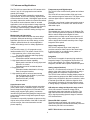
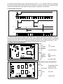
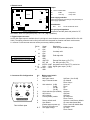
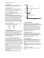
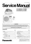
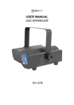
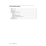
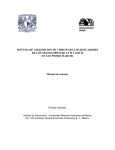
TM-1010
PROGRESSIVE SCANNING
HIGH RESOLUTION CAMERA
(REV. 2)
OPERATIONS &
MAINTENANCE MANUAL
JUN 1996
Covered by U.S. Pat. # 6259478 B1
1.1 Features and Applications
Frame memory and Digital output
The TM-1010 has a built-in frame grabber and a frame
memory.
The 10-bit A/D converter provides 1024 gray levels
with maximized signal-to-noise ratio. The output can be
real time digital output or captured image (frozen
picture).
The digital output format is always progressive scan at
the maximum rate of 15 frames / sec. and is RS-422
differential output.
The TM-1010 is a state-of-the-art CCD camera which
uses a 1 inch 1K x 1K progressive scan interline
transfer CCD imager.
This CCD camera offers outstanding compactness,
high resolution, built-in frame memory, asynchronous
reset and electronic shutter, 10-bit digital output as well
as analog video and a number of technical innovations.
The camera's various features allow for versatile
applications, such as high resolution image capturing,
machine vision, computer graphics, gauging, avionics,
microscopy, medical imaging, character and fine
pattern recognition, document reading and high end
surveillance.
Variable clock rate
The standard pixel clock frequency is 20 MHz but TM1010 can be programmed to operate at 10 MHz and 5
MHz in ordet to adapt various higher bit frame
grabbers which normally runs at slower speed for 10bit processing. Also, lower speed reduces the system
noise to degree and increase sensitivity due to longer
integration at the speed.
Miniaturized and light weight
All PULNiX cameras are built with the same design
principles: Solid state technology; miniaturization;
application specific such as custom design, remote
imagers, special functions for various application
needs; robust design even for military applications.
Async image capturing
The TM-1010 captures async reset image and
provides continuous video output of the same image.
It makes simpler for an ordinary frame grabber to
capture the async reset images.
Imager
The TM-1010 uses a 1K x 1K progressive scan
interline transfer CCD. The reason of such CCD is,
1. High resolution (1024 x 1024 active pixels)
For very high resolution and image quality.
2. Square pixel (9.0 x 9.0 µm)
Precise dimensional measurement ability.
3. High speed electronic shutter capability
High dynamic resolution of moving object and
electronic iris control.
Eliminates a need of mechanical shutter.
4. Progressive scan
Eliminates interlace deterioration of image.
Ease of computer interface.
5. High sensitivity and low noise at fast scanning
Can drive faster than 20 MHz x 2 pixel clock
rate. (40 MHz output clock)
Excellent S/N ratio (>50 dB).
Micro lens built-in.
Integration
The TM-1010 is capable of capturing high resolution
integration images. The integration can last from 1/15
sec to a few seconds. For uniform and low noise
integration, PULNiX offers a peltier cooled CCD option.
Analog output (interlace)
Since 1K x 1K cameras are no longer in TV format, the
display of the video signal is only achieved by using a
frame grabber and computer or special monitor.
The TM-1010 has a feature of analog display output for
signal monitoring purpose from BNC connector but the
signal is not processed for the scan conversion in order
to maintain good S/N ratio. While the digital is 10-bit
non-interlace, the analog is 8-bit non-interlace output.
If analog display is important, PULNiX offers TM-1040.
Asynchronous reset
The TM-1010 can be reset with external reset pulse
(VINIT).When VINIT is enabled at Async mode, the
camera keeps discharging from CCD and with VINIT
leading edge (negative going pulse), it resets the
internal timing and starts integrating the image for the
preset period of shutter timing and outputs the async
shutter video.
This feature is especially important to capture moving
objects at the precise location of the field of view such
as belt conveyer, fast event observation and still
picture capturing.
A/D reference voltage and dynamic range control
10-bit A/D converter’s reference voltage can be
controlled by back panel switches or RS-232C. The
high reference and low reference variation provides
A/D or signal processing dynamic range to maximize
CCD characteristics.
Remote RS-232C copntrol
The back panel mode switch, gain control, shutter
speed, A/D reference functions and the data preset are
controlled by RS-232C communication.
NOTE: TM-1010 has a microlens CCD.
2
2. SPECIFICATIONS
Imager
Imager
Total pixels
Photosensitive pixels
Photosensitive area
Pixel size
Output sensitivity
Micro lens
1" Progressive scan interline transfer CCD
1024 (H) x 1024 (V)
1008 (H) x 1018 (V)
6 + 10 ob(H), 4 + 2 ob (V)
9.1 (H) x 9.2 (V) mm
9.0 (H) x 9.0 (V) µm
12 µV/eBuilt-in
Blemish
Point defect
No defect
<5
<10
<20
Class 0
Class 1
Class 2
Class 3
Cluster
0
0
<4
<8
Column
0
0
<2
<4
Peak quantum efficiency: 38%
1.0
O.9
TM-1001
0.8
0.7
Relative Sensitivity
0.6
0.5
0.4
0.3
TM-1000
0.2
0.1
0
300
400
500
600
700
800
900
1000
1100
Wave Length (nm)
TM-1001 SPECTRAL RESPONSE
Camera
Scanning
Sync
Pixel clock
TV resolution
Minimum illumination
S/N ratio
Video output
Display mode video
AGC
MGC
Gamma
Lens mount
Power requirement
Operating temperature
Vibration and shock
Size
Weight
Power cable
Digital cable
Power supply
1024 lines 15 Hz ( Single channel output from CCD, single channel
output for read out)
Internal / External auto switch
HD / VD, 4.0 Vp-p impedance 4.7 KΩ
fHD = 15.75 KHz
fVD = 15 Hz
20.034 MHz, output clock: selectable 20 MHz, 10 MHz and 5 MHz
Analog :700 (H) x 800 (V) , Digital: 1008 (H) x 1018 (V) pixel resolution
2.0 lux, f = 1.4 without IR cut filter
50 dB min. AGC = Off
Analog
1.0 Vp-p composite video, 75 Ω , sync negative
Digital
10-bit RS-422 differential output
Data clock = 20.034 MHz (10 MHz, 5 MHz)
Analog only fHD = 15.75 KHz, fVD = 15 Hz, Non-interlace
Off
Manual gain adjustable ( 6 dB to 26 dB )
1.0
C-mount........1" lens format
12 V DC 500 mA (700 mA for driving RS-422)
-10° C to 50° C
Vibration: 7G (200Hz to 2000Hz), shock: 70G
51mm (H) x 67 (W)mm x 152mm (L) (2.01" x 2.64" x 5.98" )
330 grams ( 11.6 oz )
12P-02
30DG-02-10 (10-bit cable)
K25-12V or PD-12
3
TM-1010 1K X 1K HIGH RESOLUTION ASYNCHRONOUS RESET FULL FRAME SHUTTER CAMERA
The TM-1010 is designed to accommodate a high resolution, ON-LINE inspection reset mechanism with full
frame shutter. It takes external horizontal sync to lock the camera and VINIT pulse for resetting the camera
asynchronously.
The shutter speed can be controlled by either an external double pulse or internal shutter speed control with a
10-position dial switch on the back panel.
1. Discharge Principle of CCD
1.1 Substrate Drain Shutter Mechanism
Normal operation requires the CCD chip to construct an individual potential well at each image cell. The potential
wells are separated from each other by a barrier. The barrier is sequentially removed to transfer the charge from
one cell to another by pixel clock. This is the basic principle of the CCD operation for charge transfer.
The substrate drain vertically moves the charges. When excess potential is applied to substrate underneath each
cell, a potential barrier is pulled down to release the charge into the drain. This can happen to all the cells
simultaneously, whereas normal CCD shuttering is achieved with a horizontal charge shift to the drain area by
interline transferring or reverse transferring of the frame transfer chip.
Photo cell potential distribution
Surface
CCD surface
+
Potential barrier
Si substrate
Vsub = normal mode
Charge drain to substrate
Vsub = shutter mode
1.2 Asynchronous shutter
For Async Shutter mode, set jumper W5 of bottom board open and provide external Hd for phase locking. When
the negative going reset pulse is applied, the camera will latch the falling edge to its next horizontal drive and
reset vertical sync timing immediately. Therefore, the horizontal phase won't be interrupted. The TM-1010
asynchronous camera outputs a full frame of shuttered video in progressive scanning format from a frame buffer.
The frame buffer is updated upon receiving negative reset pulse.
ASYNC RESET
VINIT
VD
SG (TRANSFER GATE)
DISCHARGE PULSE
PROGRESSIVE OUTPUT
VIDEO
OLD VIDEO
IN MEMORY
SHUTTER
VIDEO
4
SAME VIDEO FROM
FRAME MEMORY
2. Shutter Speed Control
2.1 External pulse width control mode
X
External
Double
pulse
Hd
Internal Vinit
9H
Transfer Gate
Pulse
9H
X
Exposure Time
Discharge pulse
Composite
Video
For External Pulse Mode, set dial switch to "9". Apply a pulse width control VINIT signal, which can be generated
from an external event trigger, to the camera. Internal reset pulse will be latched to Hd and at 9th HD timing from
external pulse leading edge ( negative going edge ), CCD discharge pulse is generated to clear the images.
The internal VINIT is generated at the following edge ( positive going edge ) of the external pulse and it resets
internal timing including the video sync.
The shutter speed is the same as the external pulse width but the integration delays 9H from the leading edge.
For immediate reset option, please contact PULNiX.
One frame of video output will start from the rising edge of the pulse width control for progressive format.
The camera will output the same video from memory when VINIT is kept high (5V) and update the image upon
receiving next pulse. At async mode, with external pulse input high, the video output is disabled as the camera
keeps discharging CCD image and only provides black video.
2.2 Internal Fast reset mode
External pulse
min. 2H
Hd
Internal Vinit
9H
Transfer Gate
Pulse
Exposure Time
Purge pulse (discharge)
Composite
Video
5
For Internal Fast Reset Mode, set the 10-position dial switch from "1" to "4". When fast reset mode is selected,
the camera resets with internal VINIT timing, which is latched to Hd, and video output is also synchronized with
internal VINIT timing without further delay. The shutter speed is controlled by the dial switch.
2.3 Internal Slow reset mode
External pulse
min. 2H
Hd
Internal Vinit
9H
Transfer Gate
Pulse
9H
Discharge pulse
EXPOSURE TIME
Composite
Video
With the Internal Slow Reset mode selected, the camera operates the reset and shutter in the same means as
the external Double Pulse mode. When external VINIT pulse is applied, internal VINIT is latched to Hd and the
second internal VINIT signal is generated to set up the shutter speed period. The shutter speed is controlled by
setting the dial switch from "5" to "8". Video output timing starts right after the second internal VINIT. For the
timing of the second internal reset, LPULSE output of 31-pin connector can be used.
3. Top Board Layout and Adjustment
Preset
AGC
MGC
J1
W1
1
VR1 AGC
2.0 V
17
J4
W5
VR2 AGC MAX
1.5 V (22 dB)
W6
VR5
VR3
No
mount
VR1
12
1
W3
VR2
VR4 No mount
VR5 VR
mechanical center
ON
J1
J3
W2
OFF
1
2
J2A
1
15
W8
W7
1
J8
18
TM-1010 SIGNAL BOARD TOP
Jumpers
W1 AGC/MGC
W2 Gamma
W3 Down load
W4 CAL
w5 - W8
MGC
Set to 1.0 (OFF)
Open
for chassis GND
Middle boards Layout and Adjustment
TP1
VR1
J10
W5
W4
Preset
VR2 PED
VR1
W3
W2
W7
J5
W1
ON
OFF
VR2
11
1
20
10
W6
TM-1010 MEMORY BOARD BOTTOM
6
D/A reference
Jumpers
W1
Gamma
W2
DL
W3
ER
W4 - W7
Set pedestal at 50 mV
of video (analog)
TBD (Vin = V out)
Set to OFF
Chassis GND
4. Bottom board
Jumper
XTAL
W1
VR1
W9
W2
DC-DC
W1 - W4 for chassis GND
W9
5VDR
W17
+10V adj
Keep short
Keep I side
1
TP1
Power supply selection
J7
W17
10
W3
W4
J5
11
10
Select internal jumper W10 through W16 (back side) for
power supply optimization.
Potentiometer
20
1
VR1
PLL
Set at mechanical center
Ext. sync input impedance
Jumpers W5 and W6 (back side) select for 75 Ω
termination. When it is open (factory set), it is 4.7 KΩ (high impedance).
TM-1010 POWER BOARD TOP
5. Digital output connector
An EIA-422 digital output is available from 31-pin high-rel, micro-miniature connector (Airborn MP221-031-2432200). The mating connector can be firmly secured to the receptacle for vibration and shock environments.
A common D-sub connector was not used to prevent any vibration problems.
1
16
31
17
6. Connector Pin Configurations
C DE
AB
5
DWN
RS-232
F01 2
89
8
MODE
3
Gain selection (6 dB)
“
(9 dB)
“
(12 dB)
“
(16 dB)
Clock selection (20,10,5MHz)
A/D Vref low
A/D Vref high
Freeze (ENINT) enable
4
POWER
VIDEO
DIGITAL
External Vinit input or VD (TTL)
Ext. HD sync input (TTL)
Integration control input (TTL), active low
Digital video output ( 10-bit )
"
Mode control switch
Normal mode
MGC gain control
Async / Manual shutter
34 5
67
UP
2 34
901
Description
Pixel clock(20.034MHz) output
"
Line data valid
"
Field data valid
"
6-1.
0
1
2
67
SHUTTER
Pin No
Signal
1
CLK+
17
CLK2
LDV+
18
LDV3
FDV+
19
FDV4
GND
20
VINIT/VD
5
EXT. HD
21
INTEG. CONT
6 - 15
DO0+ - DO9+
22 - 31 DO0 - - DO916
GND
5
6
7
8
9
A
TM-1010 Back plate
B-F
Factory default recall
User default
(Default page at power up)
Press Up and power on
User page storage
7
Up/Down (6 to 22 dB)
Up: Manual
Down: Async
Up to set
Down
Up
Down
Up/down
Up/Down
Up/Down
Up: Real time
Down: Freeze
Up/down: recall factory default
Up: save data (latest data)
Down: Load user default data
Calibration mode
Up: save
Down: Recall
9
1
2
3
11 12
4
SH CONTROL
8
10
9 0 1
7
8
7
6
5
2
3
6 5 4
12-PIN Connector
1. GND
7. VD In
2. +12V DC
8. GND
3. GND
9. HD In
4. Video Out
10. GND
5. GND
11. Integration Control
6. VINIT In
12. GND
NOTE: TM-9700, TM-540, TM-720, TM-745,
TM-1001 pin compatible.
Shutter Control Switch
Manual shutter mode
Async reset mode
0
no shutter
no shutter
1
1/60
1.0H 1/16000
2
1/125
2.0H 1/8000
3
1/250
4.0H 1/4000
4
1/500
8.0H 1/2000
5
1/1000
16 H 1/1000
6
1/2000
32 H
1/500
7
1/4000
64 H
1/250
8
1/8000
128H
1/125
9
1/16000 Shutter determined by pulse width
Mode 0:
Mode1-4:
Mode5-8:
Mode 9:
Normal mode
Fast mode
Slow mode
Pulse width mode
3.4.4 6-pin RS-232C Connector (HR10A-7P-6P)
RS-232
PC-6P
1
2
3
4-6
RXD
TXD
RTS
GND
RS-232
CABLE
TM-1040
TM-1010
TMC-9700
RxD
1
TxD
2
RTS
3
IBM-PC
9-pin c
red
white
green
GND 4
GND 5
black
GND 6
shield
HR10A-7P-6P
6 pin connector
7. Monitor display mode
For the monitor information connect BNC output to multiscan or equivalent video equipment.
Since the frame rate is 15 Hz, it is not easy to see the detail on a monitor. The analog output of TM-1010 is more
likely to be monitored by oscilloscope for the waveform analysis. Analog signal monitoring is not using the full
advantage of 10-bit signal processing.
For digital output application, use the digital output connector.
Multi-sync black and white monitors
PULNiX offers slow decay phosphor CRT type non-interlace monitor (42-5001).
Electrohome EVM942 /1242 or equivalent model can be used for TM-1010 display mode.
Some of these monitor may not accept 15 Hz vertical sync. Please contact PULNiX for the modification or
information.
8
8. Frame Memory
The TM-1010 has a built-in frame memory which
outputs progressive scanning images at 15 Hz rate
(15 frames per sec). This feature provides the following
advantages:
1. Asynchronously captured images are output as
standard continuous video signals so that a monitor or
frame grabber can display or process without a special
asynchronous video grabber.
2. Integration video is continuously output until the next
capture. Normally, the camera cannot output the video
signal during the integration, and the periodic
integration causes a blinking video signal. The TM1010 memory keeps the stored image until the next
image is completed so that there is no blank interval
during integration.
3. Digital format of the video output can be used as
direct interface with the computer. The format is
progressive.
How to activate the frame memory?
A.
Asynchronous reset mode (Select switch of
the back panel for ASY...async)
When External VINIT is high ( 5V), the TM-1010
expects the async pulse input. It resets at the negative
going pulse edge and captures the frame regardless of
the shutter speed (fast or slow mode). The video
output is kept disabled as the CCD is discharged
continuously during VINIT high. When the first VINIT
pulse comes in, it resets the timing and captures the
image. The captured image is kept until next pulse is
applied for new image.
If the switch is NRM (normal mode....manual shutter
mode), the video output is real time with manual
shutter.
B.
Integration
Activate EN INT (Enable Integration) of 31-pin
connector (#22) by connecting to GND then input
INTEG control(#6) as active low (TTL). When it is low,
the TM-1010 keeps integrating and, upon the rising
edge of the INTEG control pulse, it captures the frame
and keeps it until next end of integration. When EN INT
is high (open), video output is in real time without
freezing and one frame of the integrated image
appears upon ending of INTEG control pulse (during
INTEG control low, it keeps the previous image but
when INTEG is high it only holds one fame).
FDV(Field Data Valid) is disabled during the integration
and the vertical pulse starts when the image is output.
9. Progressive scanning
Standard TV system scanning is 525 line interlace
scanning as specified in RS170. Every other
horizontal line (ODD lines and EVEN lines) is scanned
at a 60 Hz rate per field, and completes scanning with
two fields (one Frame) at 30 Hz rate.
9
Because of the interlace scanning, vertical resolution of
CCD cameras is limited at 350 TV lines regardless of
horizontal resolution. When electronic shutter is
applied, the CCD can only hold one field of charges at
each exposure. Therefore, the vertical resolution of the
electronic shutter camera is only 244 TV lines.
This is the same situation for HDTV format camera
since it is interlaced scanning and the vertical
resolution of shuttered image is 500 lines.
The TM-1010 uses a state-of-the-art CCD called a
"Progressive scanning interline transfer CCD" which
scans all lines sequentially from top to bottom at one
frame rate (15 Hz). Like a non-interlace computer
screen, it generates a stable crisp image without
alternating lines and provides full vertical TV resolution
of 1000 lines
(a monitor display may not be able to
show 1000 lines due to monitor resolution and interlace
scanning of the analog output). The interline transfer
architecture is also important to generate simultaneous
shuttering. This is different from full frame transfer
architecture which requires a mechanical shutter or
strobe light in order to freeze the object motion.
The TM-1010 outputs the progressive scanned
image with an electronic shutter in two different
formats:
1. Progressive scanning digital output
The CCD signal goes through A/D and D/A converters.
The frame memory is capable of capturing async and
integration video without having special frame
grabbers.
10-bit digital output is available from 31-pin connector
with EIA-422 format (40 MHz clock rate).
2.Non-interlace scan analog output
The TM-1010 outputs non-interlace video for monitor
display. The digital output of 31-pin connector is also at
15 Hz with a 20 MHz pixel clock but it is not interlace
scan (progressive scan).
Mode control functions
-0. Normal mode
Camera outputs real time normal video signal without
elctronic shutter or asynchronous functions.
CCD output
voltage
-1. MGC gain control
CDS amplifier gain can be controlled by up/down
switch. The minimum gain is 6 dB and the maximum
gain is set internally (factory set is 22 dB)
500 mV
-2. Async / Manual shutter selection
The electronic shutter mode is slected by up (manual)
and down (async) switch.
When it si manual mode, the shutter speed is
programmed by shutter speed switch and when async
shutter is selected, the shutter timing works with VINIT
(async reset pulse). If VINIT is kept high, it keeps
discharging CCD and when negative going pulse
comes in, it resets the timing and captures a image
and holds until next pulse comes. The async shutter
speed is also slected by the shutter selection switch.
-3 and -4. Gain selection
Fixed specific gain is recalled by selcting 3 or 4 and
pressing up/down switch up or down.
3 - up
6 dB
3 - down
9 dB
4 - up
12 dB
4 - down
16 dB
-5. Clock frequency selection
Three different frequency is selectable by up und down
switch. The standard frequency is 20 MHz and 1/2 (10
MHz) and 1/4 (5.0 MHz) of standard frequency is
selected. Since TM-1010 is 10-bit otuput and many
frame grabbers with 10-bit or 12-bit input may not have
20 MHz capability, it is convenient to have such
frequency electable feature.
-6 and -7. A/D reference voltage control
CCD output itself has over 60 dB of dynamic range.
However, signal normally used to display or capture is
not such wide range. For instance, if amp gain is set at
12 dB (4X) and the display is 100 IRE which saturation
is 714 mV, actual signal from CCD is 714/4 = 178 mV.
This is 1/3 of KAI-1001 imager saturation. By adjusting
Vref, the full dynamic range at a specific gain can be
obtained.
When low light and high sensitivity is required, the
reference can be set at narrow range so that small
signal can be digitally amplified and also the gray level
can be shifted to middle region for easy observation
and processing.
The input signal to A/D is from 2.2 V to 3.7 V and
typical factory set is VL = 2.2 V and VH = 3.2 V.
KAI-1001
Saturation
Vref high
A/D dynamic range
Vref low
Input light
-8. Freeze (ENINT) enable
The internal frame buffer can freeze the image by
selecting this function. When up/down switch is pushed
up, it is real time image. When it is down, it freezes the
final image. This freeze mode is also used for
integration control. At freeze mode, TM-1010 can be
used to integrate (log exposure) by controlling INTEG
control input on 12-pin connector (pin #11). It keeps
integrating as long as the pin #11 is low and grab a
image upon the integration is over.
-9. Factory default recall
When this mode 9 is selected at power up, camera
starts with the factroy set parameter. When camera is
already powered, select the switch #9 and press
up/down switch up to recall factory default. (User
cannot change this parameter)
-A. User default page
This page is default page for camera to start up. When
camera is powered up, it start operating with
parameters stored in page #A except switch positions
of #9 (factory set), #B through #F (user set specific
pages).
The last changes during optimization should be stored
in the page #A so that the default will be recalled upon
next power up.
-B through -F User pages
User can store its specific parameters in pages from B
through F.
10
10. Digital output pulses
Digital Video
Differential line-driven, 10-bit parallel signal with EIA-422 format.
100Ω output termination impedance.
Output from 31-pin connector. The mating connector: Airborne MP211-031-113-4300
Please consult digital cable information. eg. 50-1301, 30DG-02-10 (10-bit), 2m cable
Line Data Valid (preliminary)
Differential line-driven signal with EIA-422 format.
It is active high (+ side is higher than - side) during the transfer of each line of data........Horizontal line read out.
HD
1N = 49.91 ns in 20 MHz mode
99.83 ns in 10 MHz mode
199.66 ns in 5 MHz mode
130N
1N
LDV
131N
1H = 1272N
6N (OB)
8N
DIGITAL
DATA
264N
1008N (Active Data)
Frame Data Valid (preliminary)
Differential line-driven signal with EIA-422 format. It is active high during the transfer of each frame data. During
integration, both LDV and FDV are kept low and restart upon the completion of integration.
VD
9H
FDV
9H
1V = 1050H
2H (OB)
DIGITAL
DATA
32H
1018H (Active Data)
Pixel clock
Differential line-driven signal with EIA-422 format. The frequency is 20.034 MHz (standard)
50 ns
PIXEL CLOCK
(20 MHz Mode)
5 ns
50 ns
Delay at A/D in = 2N
Delay at D/A out = 7N
DIGITAL DATA
11
11. Connector and cable
Digital output connector is optional.
Mating connector ordering information: PULNiX part No. 15-1623
Airborn P/N: MP211-031-113-3400
Straight Backshell (cover):
15-1624
MM254-031-000-0000
Cable assembly:
Digital cable
30DG-02-10
50-1301-05
12-pin connector and cable: Standard cable is 12P-02 (2m, 8 conductor cable) for power and external controls.
12. Physical Dimensions
67.0
172.0mm
152.0 mm
PULNiX
51.0
PROGRESSIVE SCAN
7.0
40.0mm
B CDE
3xO.25"-20 UNC-2B
(A)
F 01 2
34 5
23
4
89
7 A
8
67
MODE RS-232
UP
6
SHUTTER
9 01
80.0mm
DWN
VIDEO
A
POWER
A
A
cL
24.6
B
B
B
DIGITAL
3xM6x1.0
(B)
12.0
20.0
40.0mm
12
72.0mm
5
13. DIGITAL CABLE ASSEMBLY
30DG-02-10 (10-bit cable)
P/N 50-1301-10 for TM-1010 Full function cable
TM-1010 PIN CONFIGURATIONS
1
16
31
TM-1010 31-pin connector
TM-9700
17
Pin Signal
Cable
Pin Signal
Cable
1
2
3
4
5
6
7
8
9
10
11
12
13
14
15
16
OR 1RED
GRY 1RED
WHT 1RED
YLW 1RED
PINK1RED
OR 2RED
GRY 2RED
WHT 2RED
YLW 2RED
PINK2RED
OR 3RED
GRY 3RED
WHT 3RED
YLW 3RED
PINK3RED
SHIELD
17
18
19
20
21
22
23
24
25
26
27
28
29
30
31
OR 1BLUE
GRY 1BLUE
WHT 1BLUE
YLW 1BLUE
PINK1BLUE
OR 2BLUE
GRY 2BLUE
WHT 2BLUE
YLW 2BLUE
PINK2BLUE
OR 3BLUE
GRY 3BLUE
WHT 3BLUE
YLW 3BLUE
PINK3BLUE
Pin Signal
Cable
Pin Signal
Cable
1
2
3
4
5
6
7
8
9
10
11
12
13
14
15
16
17
18
19
OR 1RED
GRY 1RED
WHT 1RED
20
21
22
23
24
25
26
27
28
29
30
31
32
33
34
35
36
37
OR 1BLUE
GRY 1BLUE
WHT 1BLUE
CLK+
LDV+
FDV+
GND
HD
D0+
D1+
D2+
D3+
D4+
D5+
D6+
D7+
D8+
D9+
GND
CLKLDVFDVVINIT/VD
INTEG
D0D1D2D3D4D5D6D7D8D9-
37-PIN D-SUB CONNECTOR PIN CONFIGURATIONS
1
19
37
20
37-pin D-SUB connector rear view
CLK+
LDV+
FDV+
N/C
N/C
D0+
D1+
D2+
D3+
D4+
D5+
D6+
D7+
D8+
D9+
GND
VINIT
N/C
N/C
13
OR 2RED
GRY 2RED
WHT 2RED
YLW 2RED
PINK 2RED
OR 3RED
GRY 3RED
WHT 3RED
YLW 3RED
PINK 3RED
YLW 1RED
YLW 1BLUE
CLKLDVFDVN/C
N/C
D0D1D2D3D4D5D4D6D7D8GND
N/C
INTEG
OR 2BLUE
GRY 2BLUE
WHT 2BLUE
YLW 2BLUE
PINK 2BLUE
OR 3BLUE
GRY 3BLUE
WHT 3BLUE
YLW 3BLUE
PINK 3BLUE
SHIELD
PINK 1BLUE
14 TM-1010 RS-232C CONTROL
The TM-1010 can be controlled its built-in
microcomputer chip (CPU) by external RS-232C
interface. The internal CPU controls TM-1010
operation mode and DSP parameter changes.
(Contact PULNiX for the TM-1040 software disket)
14-4-2 Async shutter mode
STX, “SA”,”0” - “9” or “S”,ETX
02H, 53H,41H, 30H - 39H, or 53H ,03H
It enables async shutter mode.
14-1. RS-232C communication default condition
Parity :
None
Data :
8 bit
STOP :
2 bit
Baud rate :
9600 bps
( If other communication condition is required, please
contact PULNiX.)
14-3-3 Direct shutter mode
STX, “SX”, “1A0”, ETX
02H, 53H, 58H, 31H,41H,30H, 03H
It selects a mode for external shutter speed control.
Hexadecimal shutter number (3 digit) follows “SX”
command. (eg. “1A0” = 416H, shutter speed = (1050416) = 634H = 20 msec...1/50 sec). It moves shutter
discharge pulse at every 1H (32 µsec.) period
from 0 (no shutter) to 1049 H (=1/32,000 sec.).
14-2. RS-232C command
The TM-1010 command packet starts with STX (Start
of Text = 02H) and then followed by Command Code
(C.C. ....one alphabet) , Command option parameter
and ETX (End of Text = 03H) to end.
One packet is 8 bit ASCII code.
When a packet is received by TM-1010 ( ETX:03H is
detected), it reads internal packet of the receiver buffer.
If it is the correct packet then it processes the
parameters based on the command. When the process
is completed, it sends a completion signal (AK packet).
If an error is detected, No-go signal (NK packet) is sent
back and disregards the packet signal in the buffer.
When NK packet is sent from TM-1010, the host must
correct the error and resend the packet.
Example: Executing shutter control
In order to set EE mode, The C.C. packet is sent as
follows,
STX, “S”, “E”, ETX
02H,53H,45H,03H
where “S”.....Shutter control command mode
“E”.....EE (auto-shutter) mode
The TM-1040 will send back
STX,ACK,ETX
or
STX,NAK,ETX
02H,06H,03H
02H,15H,03H
14-4 Command M
Function:
Changes memory mode between
Freeze and free -run mode
Freeze mode:
STX, “M”, “0”, ETX
02H,4DH, 30H, 03H
Free-run mode: STX, “M”, “1”, ETX
02H, 4DH, 31H, 03H
14-5. Command G
Function:
A/D pre-amp gain control
First value next to “G” command is A channel, second
value is B channel.
STX, “G”, “FF”, “FF”, ETX
FFH = gain 255
02H, 47H, 46H,46H, 46H,46H, 03H
STX, “G’, “12”, “10”, ETX
02H, 47H, 31H, 32H, 31H, 30H, 03H
Channel A = gain control value 18
Channel B = gain control value 16
It changes the gain by hexadecimal 2 digit.
VO = 2/255 X SET VALUE + 2.0 V
Value : 0 to 255
VO = D/A output voltage
(Vo min = 2.0 V...8 dB, V0 max = 4.0V...28 dB)
14.3 Command S
Function: Shutter control command
Shutter mode selection and shutter speed setting.
14-3-1 Manual shutter mode
STX,”SM”, ”0” -”9” or “S”, ETX
02H,53H,4DH, 30H - 39H or 53H,03H
It enables manual shutter operation. Select “0” - “9”
shutter speed. It over-rules the back panel setting.
When “S” code is selected, the back panel shutter
switch is activated for the speed selection.
14-6. Command V
Function:
A/D reference voltage control
First value next to “v” command is Vref top, second
value is Vref bottom.
STX, “V”, “7E”, “64”, ETX
7EH = Vref top: 126
64H = Vref bottom: 100
02H, 56H, 37H,45H, 36H,34H, 03H
14
14-7. Command W
Function: Write data to the selected pages or
calibration data table.
14-7-1 Saving to page (from page 9 through F)
STX, “W”, “A” - “F”, ETX
02H, 57H, 41H - 46H , 03H
(“page 9” is factory use only)
14-7-2 Saving to calibration table “WU” command
“WU” + [data string 32,byte]
See EEPROM partition table
Gain control
GAIN (dB)
30
20
14-7-3 (Factory set mode “WS” command)
10
14-8 Command Z
Function: Select and read a memory page and set the
pre-programmed data.
STX, “z”, “A” - “F”, ETX
02H, 5A, 41H - 46H , 03H
It loads the data.
1.0
14-9. Command R
(Pulnix software disk is available)
Function: Output data values of camera memory.
14-10-1 Report from RAM “R R” command
Reads out the current setting and the response format
from the camera is,
STX, ACK, “R”, [data] (20 byte ASCII), ETX
14-9-2 Report from pages “R 9-F” command
Camera responses,
STX, ACK, “A”(page), [data]
14-9-3 Report from user calibration table
“R U” command
Camera response is,
STX, ACK,”U”, [data]
14-9-4 Report from factory set
“R S” command
camera response is,
STX, ACK, “S”, [data]
For detailed parameter, please contact PULNiX.
Note: When RS-232C is active, back plate switches
are over-written and not functioning. In order to
activate back plate switches, power off and power
up again.
15
2.0
3.0
4.0
VOLTAGE (V)