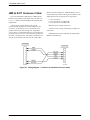
1
COMSPHERE 3825PLUS MODEM USER’S GUIDE Document No. 3825-A2-GB30-41 February 2002 COMSPHERE 3825Plus Modem COMSPHERE 3825Plus Modem User’s Guide 3825-A2-GB30-41 6th Edition (February 2002) Changes and enhancements to the product and to the information herein will be documented and issued as a new release or a limited revision of this manual. The 3825Plus modem connects to the Public Switched Telephone Network (PSTN) using the Universal Service Order Code (USOC) for Permissive mode, RJ11C. An RJ14C jack must be used to connect a two-line telephone to the modem. The Canadian equivalent to RJ11C is CA11A and the Canadian equivalent to RJ14C is CA14A. For connection to an analog private line, an adapter cable should be used to facilitate connection to a JM8 jack. The Canadian equivalent is CA40A. FCC Registration number: Ringer Equivalence number (REN): Canadian Certification number: Canadian DOC Load number: (See label on modem) (See label on modem) (See label on modem) (See label on modem) Warranty, Sales, and Service Information Contact your local sales representative, service representative, or distributor directly for any help needed. For additional information concerning warranty, sales, service, repair, installation, documentation, training, distributor locations, or Paradyne worldwide office locations, use one of the following methods: • Via the Internet: Visit the Paradyne World Wide Web site at http://www.paradyne.com • Via Telephone: Call our automated call system to receive current information via fax or to speak with a company representative. — Within the U.S.A., call 1-800-870-2221 — Outside the U.S.A., call 1-727-530-2340 Trademarks All products and services mentioned herein are the trademarks, service marks, registered trademarks or registered service marks of their respective owners. Printed on recycled paper COPYRIGHT 1999, 2002 Paradyne Corporation. All rights reserved. This publication is protected by federal copyright law. No part of this publication may be copied or distributed, transmitted, transcribed, stored in a retrieval system, or translated into any human or computer language in any form or by any means, electronic, mechanical, magnetic, manual or otherwise, or disclosed to third parties without the express written permission of Paradyne Corporation, 8545 126th Avenue North, P.O. Box 2826, Largo, Florida 33779-2826. Paradyne Corporation makes no representation or warranties with respect to the contents hereof and specifically disclaims any implied warranties of merchantability or fitness for a particular purpose. Further, Paradyne Corporation reserves the right to revise this publication and to make changes from time to time in the contents hereof without obligation of Paradyne Corporation to notify any person of such revision or changes. A February 2002 3825-A2-GB30-41 Safety Instructions ! Important Safety Instructions 1. Read and follow all warning notices and instructions marked on the product or included in the manual. 2. Slots and openings in the cabinet are provided for ventilation. To ensure reliable operation of the product and to protect it from overheating, these slots and openings must not be blocked or covered. 3. Do not allow anything to rest on the power cord and do not locate the product where persons will walk on the power cord. 4. Do not attempt to service this product yourself, as opening or removing covers may expose you to dangerous high voltage points or other risks. Refer all servicing to qualified service personnel. 5. General purpose cables are provided with this product. Special cables, which may be required by the regulatory inspection authority for the installation site, are the responsibility of the customer. 6. When installed in the final configuration, the product must comply with the applicable Safety Standards and regulatory requirements of the country in which it is installed. If necessary, consult with the appropriate regulatory agencies and inspection authorities to ensure compliance. 7. Input power to this product must be provided by one of the following: (1) a UL Listed, CSA Certified power source with a Class 2 or Limited Power Source (LPS) output for use in North America, or (2) a certified power source with a Safety Extra Low Voltage (SELV) output for use in the country of installation. In addition, if the equipment is to be used with telecommunications circuits, take the following precautions: — Never install telephone wiring during a lightning storm. — Never install telephone jacks in wet locations unless the jack is specifically designed for wet locations. — Never touch uninsulated telephone wires or terminals unless the telephone line has been disconnected at the network interface. — Use caution when installing or modifying telephone lines. — Avoid using a telephone (other than a cordless type) during an electrical storm. — There may be a remote risk of electric shock from lightning. — Do not use the telephone to report a gas leak in the vicinity of the leak. 3825-A2-GB30-40 January 1999 B COMSPHERE 3825Plus Modem Notices " " " " ! C January 1999 3825-A2-GB30-40 Safety Instructions Government Requirements and Equipment Return Certain governments require that instructions pertaining to modem connection to the public switched telephone network be included in the installation and operation manual. Specific instructions are listed in the following sections. United States Notice To Users Of The Public Switched Telephone Network 1. This equipment complies with Part 68 of the FCC rules. On the equipment is a label that contains, among other information, the FCC registration number and ringer equivalence number (REN) for this equipment. The label is located on the bottom of your modem. 2. Page A of this manual contains the Universal Service Order Codes (USOC) associated with the services on which the equipment is to be connected. 3. The Ringer Equivalence (REN) is used to determine the quantity of devices which may be connected to the telephone line. Excessive RENs on the telephone line may result in the devices not ringing in response to an incoming call. In most, but not all areas, the sum of the RENs should not exceed five (5.0). To be certain of the number of devices that may be connected to the line, as determined by the total RENs, contact the telephone company to determine the maximum RENs for the calling area. 4. If the modem causes harm to the telephone network, the telephone company will notify you in advance that temporary discontinuance of service may be required. But if advance notice is not practical, the telephone company will notify the customer as soon as possible. Also, you will be advised of your right to file a complaint with the FCC if you believe it is necessary. 5. The telephone company may make changes in its facilities, equipment, operations, or procedures that could affect the operation of the equipment. If this happens, the telephone company will provide advance notice in order for you to make the necessary modifications in order to maintain uninterrupted service. 6. If you experience trouble with this equipment, please contact your sales or service representative (as appropriate) for repair or warranty information. If the product needs to be returned to the company service center for repair, contact them directly for return instructions using one of the following methods: • Via the Internet: Visit the Paradyne World Wide Web site at http://www.paradyne.com • Via Telephone: Call our automated call system to receive current information via fax or to speak with a company representative. — Within the U.S.A., call 1-800-870-2221 — Outside the U.S.A., call 1-727-530-2340 If the trouble is causing harm to the telephone network, the telephone company may request that you remove the equipment from the network until the problem is resolved. 7. The user is not authorized to repair or modify the equipment. 8. This equipment cannot be used on public coin service provided by the telephone company. Connection to Party Line Service is subject to state tariffs. (Contact the state public utility commission, public service commission or corporation commission for information.) 9. The Telephone Consumer Protection Act of 1991 makes it unlawful for any person to use a computer or other electronic device to send any message via a telephone fax machine unless such a message clearly contains, in a margin at the top or bottom of each transmitted page, or on the first page of the transmission, the date and time it is sent, and an identification of the business, or other entity, or other individual sending the message, and the telephone number of such business, or other entity, or individual. In order to program this information, follow the steps outlined in the manual supplied with your fax software. 10. An FCC compliant telephone cord with modular plugs may be provided with this equipment. This equipment is designed to be connected to the telephone network or premises wiring using a compatible modular jack which is Part 68 compliant. 3825-A2-GB30-40 January 1999 D COMSPHERE 3825Plus Modem Canada Notice To The Users Of The Canadian Public Switched Telephone Network The Canadian Department of Communications label identifies certified equipment. This certification means that the equipment meets certain telecommunications network protective, operational and safety requirements. The Department does not guarantee the equipment will operate to the user’s satisfaction. Before installing this equipment, users should ensure that it is permissible to be connected to the facilities of the local telecommunications company. The equipment must also be installed using an acceptable method of connection. In some cases, the company’s inside wiring associated with a single line individual service may be extended by means of a certified connector assembly (telephone extension cord). The customer should be aware that compliance with the above conditions may not prevent degradation of service in some situations. Repairs to certified equipment should be made by an authorized Canadian maintenance facility designated by the supplier. Any repairs or alterations made by the user to this equipment, or equipment malfunctions, may give the telecommunications company cause to request the user to disconnect the equipment. Users should ensure for their own protection that the electrical ground connections of the power utility, telephone line and internal metallic water pipe system, if present, are connected together. This precaution may be particularly important in rural areas. The Load Number for this equipment is listed on a label on the modem. The Load Number (LN) assigned to each terminal device denotes the percentage of the total load to be connected to a telephone loop which is used by the device to prevent overloading. The termination on a loop may consist of any combination of devices subject only to the requirement that the total of the Load Numbers of all devices does not exceed 100. If your equipment is in need of repair, refer to the procedures in the Government Requirements and Equipment Return section. E January 1999 3825-A2-GB30-40 Safety Instructions United Kingdom Ringer Equivalence Number The Ringer Equivalence Number (REN) is a customer guide indicating approximately the maximum number of items of apparatus that should be connected simultaneously to the telephone line. The sum of the RENs should not exceed four. This value includes any BT-provided instrument which may be assumed to have a REN of 1 unless marked otherwise. The REN of this modem is 1. Connection to Leased Lines If any other apparatus, including cable or wiring, is connected between the apparatus and the point of connection to any speechband circuit, then all that other apparatus shall comply with the following: 1. The overall transmission characteristics of all that other apparatus shall be such as to introduce no material effect upon the electrical conditions presented to one another by the apparatus and the speechband circuit; and 2. All that other apparatus shall comprise only: (i) apparatus approved for the purpose of connection between the apparatus and a speechband circuit; and (ii) cable or wiring complying with a code of practice for the installation of equipment covered by this part of BS 6328 or such other requirements as may be applicable. This modem is suitable for connection to BT circuits with signalling at a nominal frequency of 2280 Hz and may be connected to multipoint or point to point circuits. The apparatus does not require signalling or otherwise use the frequency range 0 –200 Hz. No d.c. interaction is intended between the modem and the telephone network. This apparatus may be directly connected to a speechband circuit or connected to a relevant branch system for speechband circuits. Connection to Supply Mains IMPORTANT: The wires in the mains lead supplied with this equipment are coloured in accordance with the following code: Blue — Neutral Brown — Live As the colours of the cores in the mains lead of this equipment may not correspond with the coloured markings identifying the terminals in your plug, proceed as follows: • The core which is coloured blue must be connected to the terminal which is marked with the colour N or coloured black. • The core which is coloured brown must be connected to the terminal which is marked with the letter L or coloured red. All European Countries Safety Notice For pluggable equipment, the mains socket outlet shall be installed near the equipment and be easily accessible. Interconnection circuits between this modem and any other equipment should be such that the equipment continues to comply with the requirements of EN41003 for TNV (Telephone Network Voltage) circuits and EN60950 for SELV (Safety Extra Low Voltage) circuits after making connection between circuits. The power supply must be properly connected and switched on before the modem will work correctly. 3825-A2-GB30-40 January 1999 F COMSPHERE 3825Plus Modem Japan Notices This equipment is in the 2nd Class category (information equipment to be used in a residential area or an adjacent area thereto) and conforms to the standards set by the Voluntary Control Council for Interference by Information Technology Equipment aimed at preventing radio interference in such residential area. When used near a radio or TV receiver, it may become the cause of radio interference. Read the instructions for correct handling. Restrictions Due to JATE (Japan Approvals Institute for Telecommunications Equipment) regulations, only 3 attempts to dial a number are permitted in a 3-minute period. If a fourth attempt is made to dial the same number, the modem returns the ERROR return code. This restriction applies to the number dialed from the command line or from a directory. An occurrence of the restriction is canceled when a different number is dialed, or when 3 minutes have elapsed. G January 1999 3825-A2-GB30-40 Table of Contents Preface Objectives and Reader Assumptions . . . . . . . . . . . . . . . . . . . . . . . . . How to Use This Manual . . . . . . . . . . . . . . . . . . . . . . . . . . . . . . . . . . Related Documents . . . . . . . . . . . . . . . . . . . . . . . . . . . . . . . . . . . . . . v v v 1. Introduction Overview . . . . . . . . . . . . . . . . . . . . . . . . . . . . . . . . . . . . . . . . . . . . . . Features . . . . . . . . . . . . . . . . . . . . . . . . . . . . . . . . . . . . . . . . . . . . . . . 3825Plus Modem Front Panel and Status Indicators . . . . . . . . . . . . . . . . . . . . . . . . . . . . . . . . . . . . . 1-1 1-1 1-2 2. 3825Plus Modem Installation Overview . . . . . . . . . . . . . . . . . . . . . . . . . . . . . . . . . . . . . . . . . . . . . . 3825Plus Modem Package . . . . . . . . . . . . . . . . . . . . . . . . . . . . . . . . . 3825Plus Installation . . . . . . . . . . . . . . . . . . . . . . . . . . . . . . . . . . . . . DTE Connection . . . . . . . . . . . . . . . . . . . . . . . . . . . . . . . . . . . . . . . . Dial-Line Connection . . . . . . . . . . . . . . . . . . . . . . . . . . . . . . . . . . . . . 2-Wire Leased-Line Connection . . . . . . . . . . . . . . . . . . . . . . . . . . . . Telephone Connection . . . . . . . . . . . . . . . . . . . . . . . . . . . . . . . . . . . . AC Power Transformer Connection . . . . . . . . . . . . . . . . . . . . . . . . . Communications Software Installation . . . . . . . . . . . . . . . . . . . . . . . Modem Power-Up . . . . . . . . . . . . . . . . . . . . . . . . . . . . . . . . . . . . . . . Selecting Factory Configuration Options . . . . . . . . . . . . . . . . . . . . . Recovering AT Commands . . . . . . . . . . . . . . . . . . . . . . . . . . . . . . . . Initialization Strings . . . . . . . . . . . . . . . . . . . . . . . . . . . . . . . . . . . . . . 2-1 2-1 2-2 2-3 2-3 2-3 2-3 2-3 2-3 2-4 2-4 2-5 2-6 3. Fax Operation Overview . . . . . . . . . . . . . . . . . . . . . . . . . . . . . . . . . . . . . . . . . . . . . . Fax Operation . . . . . . . . . . . . . . . . . . . . . . . . . . . . . . . . . . . . . . . . . . . 3825-A2-GB30-40 January 1999 3-1 3-1 i COMSPHERE 3825Plus Modem 4. AT Commands and S-Registers Overview . . . . . . . . . . . . . . . . . . . . . . . . . . . . . . . . . . . . . . . . . . . . . . Operating Modes . . . . . . . . . . . . . . . . . . . . . . . . . . . . . . . . . . . . . . . . Command Guidelines . . . . . . . . . . . . . . . . . . . . . . . . . . . . . . . . . . . . . AT Command List . . . . . . . . . . . . . . . . . . . . . . . . . . . . . . . . . . . . . . . S-Register List . . . . . . . . . . . . . . . . . . . . . . . . . . . . . . . . . . . . . . . . . . Security . . . . . . . . . . . . . . . . . . . . . . . . . . . . . . . . . . . . . . . . . . . . . . . 4-1 4-1 4-2 4-2 4-17 4-27 5. Remote Access Overview . . . . . . . . . . . . . . . . . . . . . . . . . . . . . . . . . . . . . . . . . . . . . . Remote Access . . . . . . . . . . . . . . . . . . . . . . . . . . . . . . . . . . . . . . . . . . 5-1 5-1 A. Result Codes Overview . . . . . . . . . . . . . . . . . . . . . . . . . . . . . . . . . . . . . . . . . . . . . . A-1 B. Troubleshooting Overview . . . . . . . . . . . . . . . . . . . . . . . . . . . . . . . . . . . . . . . . . . . . . . Automatic Firmware Download . . . . . . . . . . . . . . . . . . . . . . . . . . . . B-1 B-5 C. Technical Specifications D. Pin Assignments EIA-232-E Pin Assignments . . . . . . . . . . . . . . . . . . . . . . . . . . . . . . . JM8 to RJ11 Crossover Cable . . . . . . . . . . . . . . . . . . . . . . . . . . . . . . D-1 D-2 E. CCITT V.25bis Dialing Commands and Responses Overview . . . . . . . . . . . . . . . . . . . . . . . . . . . . . . . . . . . . . . . . . . . . . . Call Request Commands . . . . . . . . . . . . . . . . . . . . . . . . . . . . . . . . . . Call Response . . . . . . . . . . . . . . . . . . . . . . . . . . . . . . . . . . . . . . . . . . . Call Answer Commands . . . . . . . . . . . . . . . . . . . . . . . . . . . . . . . . . . Program Normal (PRN) . . . . . . . . . . . . . . . . . . . . . . . . . . . . . . . . . . . Request List of Stored Numbers (RLN) . . . . . . . . . . . . . . . . . . . . . . List Stored Number Response (LSN) . . . . . . . . . . . . . . . . . . . . . . . . . . . . . . . . . . . . . . . . . Command Response . . . . . . . . . . . . . . . . . . . . . . . . . . . . . . . . . . . . . . ii January 1999 E-1 E-2 E-2 E-3 E-3 E-3 E-3 E-4 3825-A2-GB30-40 Table of Contents F. Country-Specific Configuration Options Configuration Options by Country . . . . . . . . . . . . . . . . . . . . . . . . . . F-1 Glossary Index 3825-A2-GB30-40 January 1999 iii COMSPHERE 3825Plus Modem This page intentionally left blank. iv January 1999 3825-A2-GB30-40 Preface Objectives and Reader Assumptions Appendix C lists the technical specifications of the 3825Plus modem. Appendix D provides EIA-232-E and JM8 to RJ11 crossover cable pin assignments. This manual describes how to install and operate the 3825Plus modem. It is intended for all users of the 3825Plus modem. Appendix E provides V.25bis dialing information. Appendix F shows configuration options whose validity or default values vary according to country code. How to Use This Manual The Glossary provides a description of terms used throughout this manual. Chapter 1 provides information about the 3825Plus modem’s hardware and software features, including the front panel and status indicators. Related Documents Chapter 2 provides instructions for installing the modem, selecting factory configuration options, recovering the ability to use AT commands, and using AT command initialization strings. 3980-A2-GB30 COMSPHERE 3800Plus Modems, User’s Guide 6700-A2-GY31 COMSPHERE 6700 Series Network Management System, User’s Guide 6800-A2-GE26 COMSPHERE 6800 Series Network Management System, User’s/System Administrator’s Guide Chapter 3 provides general information about fax modem operation. Chapter 4 provides instructions for displaying and changing AT commands and S-Registers. These commands control all aspects of the modem’s operation, including Security, which is described in a separate section of this chapter. Contact your sales or service representative to order additional product documentation. Chapter 5 shows how to use the Diagnostic Control Panel (DCP) of a COMSPHERE modem to access and control a remote 3825Plus modem. Appendix A lists result codes produced by the modem. Paradyne documents are also available on the World Wide Web at: Appendix B provides instructions for performing diagnostic tests when data communications problems occur, and explains the Automatic Firmware Download process. 3825-A2-GB30-40 http://www.paradyne.com Select Service & Support → Technical Manuals January 1999 v COMSPHERE 3825Plus Modem This page intentionally left blank. vi January 1999 3825-A2-GB30-40 Introduction Overview . . . . . . . . . . . . . . . . . . . . . . . . . . . . . . . . . . . . . . . . . . . . . . . . . . . . . . . . . . . . . . . . . . . . . . . . . . Features . . . . . . . . . . . . . . . . . . . . . . . . . . . . . . . . . . . . . . . . . . . . . . . . . . . . . . . . . . . . . . . . . . . . . . . . . . . 3825Plus Modem Front Panel and Status Indicators . . . . . . . . . . . . . . . . . . . . . . . . . . . . . . . . . . . . . . . . Status Indicators (LEDs) . . . . . . . . . . . . . . . . . . . . . . . . . . . . . . . . . . . . . . . . . . . . . . . . . . . . . . . . . . . 1 1-1 1-1 1-2 1-2 Overview Features The 3825Plus modem is a member of the COMSPHERE 3800 Series Modem product line. The 3825Plus is a high-speed dial modem that offers reliable asynchronous and synchronous operation over dial- or two-wire leased-line networks. The 3825Plus modem’s software defineability allows you to add enhancements and new features as they become available, with no further investment in hardware, no on-site personnel, and minimal downtime. The 3825Plus modem has a wide variety of features, including: High-speed data transfer and reliable throughput at data rates as high as 33,600 bps over dial lines is made possible by employing the latest techniques in modem modulations, and using ITU-T V.42bis/MNP Class 5 data compression and ITU-T V.42/MNP error correction. In addition to fast line speeds, the modem can send data to the DTE at speeds as high as 115,200 bps. The modem’s compatibility with a number of dialing methods and protocols, such as asynchronous AT commands and ITU-T V.25bis dialing, permits the 3825Plus to be used in a variety of applications and environments while also allowing control over modem configuration, dialing, and diagnostics. The modem offers two preset factory configurations containing the most often used modem settings. These factory presets provide quick configuration for any asynchronous or UNIX hardware-based dial environment. • Dial-Line Modulations: ITU-T V.34 (up to 33,600 bps), V.32terbo (19,200 and 16,800 bps), ITU-T V.32bis (up to 14,400 bps), V.32 (up to 9600 bps), V.22bis (2400 bps), V.22 (1200 bps), V.21 (300 bps), Bell 212A (1200 bps), and Bell 103J (300 bps). • Two-wire Leased-Line Modulations: ITU-T V.34 (up to 33,600 bps), V.32terbo (19,200 and 16,800 bps), V.32bis (14,400, 12,000, 9600, 7200, and 4800 bps), V.32 (9600 and 4800 bps), and V.22bis (2400 bps). • Class 1 and Class 2 Group III Fax modulations: ITU-T V.17 (14,400, 12,000, 9600, 7200 bps), V.29 (9600, 7200 bps) and V.27ter (4800, 2400 bps). • Convenient migration to new or optional features through software downloading. • ITU-T V.42bis and MNP Class 5 data compression. • Virtual error-free data integrity with ITU-T V.42 and MNP Levels 2– 4 error control. • Asynchronous dial DTE data rates from 300 bps–115,200 bps. • Optional Enhanced Throughput Cellular (ETC), which improves reliability and speed over cellular links. • Compatibility with the industry de facto standard AT Command set. 3825-A2-GB30-40 January 1999 1-1 COMSPHERE 3825Plus Modem • High-speed transmission using asynchronous, synchronous, or UNIX devices over full- or half-duplex dial networks or 2-wire leased lines. 3825Plus Modem Front Panel and Status Indicators • Support as a remote (tributary) device by the COMSPHERE 6700 or 6800 Series Network Management System. The front panel of the 3825Plus modem is equipped with 8 LEDs (status indicators) that monitor modem activity (Figure 1-1). • Compatibility with COMSPHERE 3800Plus, 3800, and 3900 Series modems’ Remote Access Mode, which allows users to view the configuration options of a 3825Plus modem from their front panel LCD displays. • Storage of up to 10 telephone numbers to directory locations. Status Indicators (LEDs) The 3825Plus’s status indicators continuously provide information on the modem’s operating condition. Table 1-1 lists the label, color and functionality of each status indicator. • Originate Security and three Answer Security modes. • Callback Security with telephone directory index or telephone number. • Two factory-defined configurations and two user-defined configuration areas. 3825Plus EC/SQ HS/RI CD OH/APL RD SD TR MR/Pwr 495-14694 Figure 1-1. 3825Plus Front Panel 1-2 January 1999 3825-A2-GB30-40 Introduction Table 1-1 3825Plus LEDs Label EC/SQ Color green Indicates Error Control/Signal Quality ON: The modem is in Error Control mode. Off: The modem is not in Error Control mode. Flashing; Predominantly ON: The modem is in Error Control mode and is receiving errors due to poor VF line signal quality. Flashing; Predominantly Off: The modem is not in Error Control mode and is receiving errors due to poor VF line signal quality. HS/RI green High Speed/Ring Indicate ON: Modem is operating at the rate for which it is configured. Off: Modem is operating at a lower rate than that for which it is configured. Cycling ON and Off: The Ring Indicate signal is being sent to the DTE. CD green Carrier Detect ON: The modem has detected a valid modulation carrier signal and is capable of transferring received data to the DTE. OH/APL green Off-Hook/Analog Private Line ON: The modem is off-hook and set for Dial. Off: The modem is on-hook and set for Dial. Slow Flashing: Modem is set for Leased (APL). RD green Receive Data ON: Received data is being transferred to the DTE. SD green Send Data ON: The modem is receiving data from the DTE to transmit. TR green Terminal Ready ON: The DTE has turned ON the DTR (Data Terminal Ready) signal or the modem is configured to ignore DTR. Off: The DTR signal is Off. MR/Pwr green Modem Ready/Power ON: Signifies that Power is ON if the modem is set for Dial and is on-hook. Signifies that the EIA DSR (Data Set Ready) signal is ON if the modem is off-hook or set for Leased. Off: Signifies that Power is Off if the modem is set for Dial and is on-hook. Signifies that the EIA DSR signal is Off if the modem is off-hook or set for Leased. Slow Flash: Modem is in download-only mode. Fast Flash: Modem is in cloning mode. NOTE: In Leased mode, Power is ON when the OH LED is flashing. 3825-A2-GB30-40 January 1999 1-3 COMSPHERE 3825Plus Modem 1-4 January 1999 3825-A2-GB30-40 3825Plus Modem Installation Overview . . . . . . . . . . . . . . . . . . . . . . . . . . . . . . . . . . . . . . . . . . . . . . . . . . . . . . . . . . . . . . . . . . . . . . . . . . 3825Plus Modem Package . . . . . . . . . . . . . . . . . . . . . . . . . . . . . . . . . . . . . . . . . . . . . . . . . . . . . . . . . . . . Customer-Supplied Equipment . . . . . . . . . . . . . . . . . . . . . . . . . . . . . . . . . . . . . . . . . . . . . . . . . . . . . . 3825Plus Installation . . . . . . . . . . . . . . . . . . . . . . . . . . . . . . . . . . . . . . . . . . . . . . . . . . . . . . . . . . . . . . . . DTE Connection . . . . . . . . . . . . . . . . . . . . . . . . . . . . . . . . . . . . . . . . . . . . . . . . . . . . . . . . . . . . . . . . . . . . Dial-Line Connection . . . . . . . . . . . . . . . . . . . . . . . . . . . . . . . . . . . . . . . . . . . . . . . . . . . . . . . . . . . . . . . . 2-Wire Leased-Line Connection . . . . . . . . . . . . . . . . . . . . . . . . . . . . . . . . . . . . . . . . . . . . . . . . . . . . . . . . Telephone Connection . . . . . . . . . . . . . . . . . . . . . . . . . . . . . . . . . . . . . . . . . . . . . . . . . . . . . . . . . . . . . . . AC Power Transformer Connection . . . . . . . . . . . . . . . . . . . . . . . . . . . . . . . . . . . . . . . . . . . . . . . . . . . . . Communications Software Installation . . . . . . . . . . . . . . . . . . . . . . . . . . . . . . . . . . . . . . . . . . . . . . . . . . . Modem Power-Up . . . . . . . . . . . . . . . . . . . . . . . . . . . . . . . . . . . . . . . . . . . . . . . . . . . . . . . . . . . . . . . . . . . Selecting Factory Configuration Options . . . . . . . . . . . . . . . . . . . . . . . . . . . . . . . . . . . . . . . . . . . . . . . . . Recovering AT Commands . . . . . . . . . . . . . . . . . . . . . . . . . . . . . . . . . . . . . . . . . . . . . . . . . . . . . . . . . . . . Initialization Strings . . . . . . . . . . . . . . . . . . . . . . . . . . . . . . . . . . . . . . . . . . . . . . . . . . . . . . . . . . . . . . . . . V.25bis Applications . . . . . . . . . . . . . . . . . . . . . . . . . . . . . . . . . . . . . . . . . . . . . . . . . . . . . . . . . . . . . . Synchronous Leased-Line Applications . . . . . . . . . . . . . . . . . . . . . . . . . . . . . . . . . . . . . . . . . . . . . . . AT&T Exclusive Dialing for DATAKIT Applications . . . . . . . . . . . . . . . . . . . . . . . . . . . . . . . . . . . . 2 2-1 2-1 2-1 2-2 2-3 2-3 2-3 2-3 2-3 2-3 2-4 2-4 2-5 2-6 2-6 2-6 2-6 Overview Customer-Supplied Equipment This chapter describes how to connect both provided and customer-supplied cables to the modem. In addition, it describes how to recover AT commands when the modem is in Dumb mode and how to enter initialization strings for unique applications. The following customer-supplied equipment is required to complete a data communications system using a 3825Plus modem: • A DTE (a computer or a terminal) with an available RS-232-E serial port. • A shielded RS-232-E cable with a male DB-25 connector at one end to attach to the modem. 3825Plus Modem Package After opening the modem’s package, check for damage and verify that the following items are present: • One of the following modular dial or leased network interfaces: • Quick Reference — RJ11C or RJ14C for dial applications • 3825Plus modem — JM8 for 2-wire leased network interface • For leased-line applications, a JM8 to RJ11 crossover cable (see Appendix D). • Power transformer • One 6-position, 4-wire modular cord (in selected models) If any hardware components are damaged, notify your sales representative. Return equipment using the procedures described in the Government Requirements and Equipment Return section in the front of this book. 3825-A2-GB30-41 February 2002 2-1 COMSPHERE 3825Plus Modem 3825Plus Installation The rear panel of the 3825Plus modem (Figure 2-1) has the following switches and connectors: Before installing your standalone modem, make sure your installation site is clean and well-ventilated. Allow space around the modem for installing cables and telephone cords, and make sure the modem is located within reach of the ac power outlet. The distance between your modem and DTE (computer or terminal) should not exceed 50 feet if DTE data rates exceed 19,200 bps. • An ON/Off power switch. • A power receptacle for ac power transformer. • A 25-pin DB-25 receptacle for your computer. • A 6-pin modular jack for external telephone set use only. • A 6-pin modular jack for dial (PSTN) lines or 2-wire leased lines. On/Off Power Computer Phone Line Dial or Leased-Line Network Interface PC Customer-Supplied Cable Customer-Supplied Cable 495-14695 Figure 2-1. 3825Plus Rear Panel 2-2 January 1999 3825-A2-GB30-40 3825Plus Modem Installation DTE Connection Telephone Connection Use the following procedure to connect the RS-232-E cable from the modem to the DTE: Use the following procedure to connect the modem to a single-line or two-line telephone: " Procedure " Procedure 1. Make sure the modem’s rear panel power switch is Off. 1. Insert the 6-position, 4-conductor modular plug into the jack labeled PHONE. 2. Connect the DB-25-P (male) connector on the cable to the DB-25-S (female) connector labeled COMPUTER (Figure 2-1) on the modem’s rear panel. Use a small screwdriver to tighten the cable to the modem. 2. Insert the other end of the modular cord into the telephone. 3. Connect the DB-25-P connector on the cable to the DB-25-S connector on the DTE. Use a small screwdriver to tighten the cable to the DTE. AC Power Transformer Connection Use the following procedure to connect the modem to an ac power outlet: Dial-Line Connection " Procedure 1. Make sure the modem’s power switch is in the Off position. Use the following procedure to connect a 3825Plus to the dial network interface. 2. Insert the power transformer’s cylindrical connector into the modem’s rear panel ac power receptacle labeled POWER (Figure 2-1). " Procedure 1. Insert the 6-position, 4-conductor modular plug into the jack labeled LINE, Figure 2-1. 3. Insert the power transformer into an ac power outlet. 2. Insert the other end of the modular cord into the dial network interface. Communications Software Installation 2-Wire Leased-Line Connection A personal computer commands and controls a dial modem through communications software. This software, which is installed on the PC, uses the AT command set to send instructions to the modem. A dumb asynchronous terminal, however, does not require this software since it can directly send AT commands. Use the following procedure to connect a 3825Plus modem to the 6-pin, center pair, leased-line network interface. A description of the JM8 to RJ11C crossover cable required can be found in Appendix D. " Procedure 1. Insert the 6-position, 4-conductor modular plug into the jack labeled LINE, Figure 2-1. 2. Insert the other end of the modular cord into the leased-line network interface. 3825-A2-GB30-40 The 3825Plus can be used with any major communications software. Refer to your software’s user’s guide for installation procedures. For an overview of how to use AT commands and a list of AT commands supported by the 3825Plus, refer to Chapter 4, AT Command Set and S-Registers. January 1999 2-3 COMSPHERE 3825Plus Modem Modem Power-Up NOTE If you have already changed certain configuration options, you may have lost AT command control. For example, operating in Synchronous mode or disabling AT commands results in an inability to change configuration options. To regain AT command control, refer to the Recovering AT Commands section for these procedures. Once your modem is properly connected to the DTE, dial or leased lines, and ac outlet, press the modem’s rear panel power switch to the ON position. The modem begins a power-up self-test in which all front panel LEDs momentarily light (note that this also occurs on a reset of the modem), and the Power LED remains ON. The state of other LEDs depends on your modem’s configuration. See Table 1-1 in Chapter 1. On initial power-up, the modem is in Command mode. To verify that the modem is connected and functioning properly, enter the following: TYPE: AT PRESS: Enter (Return) To change a factory template, perform the following steps (for more information on changing factory templates using AT commands, refer to Chapter 4, AT Commands and S-Registers). The screen displays OK. " Procedure If the modem does not return OK, refer to Appendix B, Troubleshooting. 1. Use the AT&F&W command to load the appropriate factory configuration to the appropriate storage area. Enter the following: Selecting Factory Configuration Options TYPE: AT&Fy&Wn Where: y is one of the following Factory configurations: After the modem passes the power-up self-test, it can be configured for operation using one of the factory preset configurations. 0 for Async Dial 3 for UNIX Dial 5 for Cellular (Mobile) 6 for Cellular (PSTN) The purpose of preset configurations is to simplify the customization your modem. These factory preset templates contain the most commonly used configuration options (straps) for Asynchronous Dial, UNIX Dial, and Cellular configurations. Your modem is shipped from the factory with the Async Dial default configuration options stored in memory. If UNIX Dial, Cellular (Mobile) or Cellular (PSTN) is more appropriate for your configuration, then you must change the factory setting as described as follows. (&F5 and &F6 are available only if ETC is installed.) and Where: 0 for Active (Saved) 1 for Customer 1 2 for Customer 2 These three configuration areas are nonvolatile memory locations. Active (Saved) contains the most recently saved changes to any configuration options. In the event of power loss, the modem retrieves these configuration options. Customer 1 and Customer 2 are user-defined configuration storage areas. 2. PRESS: 2-4 January 1999 n is one of the following storage areas: Enter (Return) 3825-A2-GB30-40 3825Plus Modem Installation The selected factory configuration is saved. If these settings are not appropriate, then change them to a setting compatible with your current application. The procedures for an AT recovery using an asynchronous terminal or personal computer are listed in the following section. Read through these procedures before performing a recovery: NOTE When configuring your modem, keep a record of its configuration options as a future reference in case the modem must be replaced. To establish a connection with a remote modem, use the D (Dial) command. Refer to Chapter 4, AT Commands and S-Registers, for more information. At least three consecutive A’s must be entered within a 2-second time interval. Recovering AT Commands AT commands are issued from asynchronous terminals and personal computers. Certain dialing methods, such as V.25bis and synchronous operation, disable the use of AT commands and place the modem into a state known as Dumb mode. The 3825Plus is capable of normal operation when in Dumb mode. However, if the setting of a configuration option must be changed, it can only be accomplished using an AT command. The AT Recovery command (AT***) places the modem into a temporary state that restores AT commands. When in this state, the modem’s previous settings are retained except for the following configuration options: • The DTE Dialer Type configuration option (&M and &Q) is set to AT If these characters are not echoed back to the DTE screen after the power-up self-test is complete, then the modem is still in Dumb mode and maintains its current configuration. Turn the modem Off and then ON again, and repeat Step 1. 2. Once the characters are echoed back to the DTE, TYPE: T*** (The case of this character must be consistent with the case used in Step 1. Mixed case prefixes such as aT or At are not recognized.) This must be entered within 10 seconds after receiving the echoed characters. PRESS: Enter The screen displays OK. • The Async/Sync Mode configuration option (&M and &Q) is set to Async • The DSR Control configuration option (&S) is set to Forced On • The LSD Control configuration option (&C) is set to Forced On 3825-A2-GB30-40 1. Turn the modem Off and then ON. The modem performs a power-up self-test in which all LEDs light. While this is running, repeatedly press the A key of your DTE’s keyboard (or keep the key depressed if your keyboard automatically repeats characters that way). Keep doing this until A’s (or a’s) appear on your DTE screen. (You may use all uppercase or all lowercase characters.) January 1999 The modem is now in AT Recovery mode, and remains in this state until a Save or power reset occurs. While in this mode, you can use AT commands to make any necessary changes to configuration options. Keep in mind that the &C command is changed to Forced On (&C0), the &M and &Q commands are changed to Async mode with AT commands enabled (&M0 and &Q0), and the &S command is changed to Forced On (&S0). If these settings are not appropriate, then reset them to a desired choice before exiting AT Recovery mode. 2-5 COMSPHERE 3825Plus Modem Synchronous Leased-Line Applications 3. To save changes, use the &W command: TYPE: AT&Wn Where: n is one of the following storage areas: PRESS: For synchronous leased-line operation, create the following initialization string with the following commands: 0 for Active (Saved) 1 for Customer 1 2 for Customer 2 TYPE: AT&F &D1 &S1 S44=n S45=n S82=n &M1 &W &Ln &W Enter Where: n is the value for the AT command. Refer to either Table 4-1 or Table 4-2 in Chapter 4 to determine the best possible values for these commands. PRESS: Enter The modem exits AT Recovery mode and returns to its previous application environment. Only the Active (Saved) area affects modem operation. To move a Customer area to Active (Saved), use the Z command. See Chapter 4 for more information. AT&T Exclusive Dialing for DATAKIT Applications Initialization Strings An initialization string contains several AT commands that are entered at once to program the modem for a specific application. For AT&T exclusive dialing for DATAKIT applications, create an initialization string with the following commands: The following initialization strings identify essential AT commands that directly impact modem operation for a particular application. If you need to modify these strings for your application, make sure additional commands are inserted somewhere in the middle of the initialization string. Whenever an &L command is used, it must appear at the end of an initialization string. TYPE: AT&F &C5 &D1 &S3 &R0 \D3 \Q1 \G1 S85=1 &M235 &W PRESS: Enter V.25bis Applications For V.25bis HDLC (High-level Data Link Control) dial-line operation, create an initialization string with the following commands. Note that the character format can be 8 data bits, no parity, and 1 stop bit; 7 data bits, odd parity, and 1 stop bit; or 7 data bits, even parity, and 1 stop bit: TYPE: AT&F &D1 &S1 &M234 &W PRESS: Enter For V.25bis bisync operation, create an initialization string with the following commands. Note that the character format must be 7 data bits, odd parity, and 1 stop bit: 2-6 TYPE: AT&F &D1 &S1 &M233 &W PRESS: Enter January 1999 3825-A2-GB30-40 Fax Operation 3 Overview . . . . . . . . . . . . . . . . . . . . . . . . . . . . . . . . . . . . . . . . . . . . . . . . . . . . . . . . . . . . . . . . . . . . . . . . . 3-1 Fax Operation . . . . . . . . . . . . . . . . . . . . . . . . . . . . . . . . . . . . . . . . . . . . . . . . . . . . . . . . . . . . . . . . . . . . . . 3-1 • You must have configured your modem according to the specifications of your fax software manual. For example: Overview The procedures for sending and receiving facsimile documents with your modem depend on the fax software you use. This chapter does not contain specific procedures, but rather information that may make it easier for you to use the documentation that came with your fax software. — Some fax software requires that the modem have Auto-Answer disabled. You can set this with the ATS0=0 command. — Some fax software requires that the modem use software flow control. You can set this with the AT \Qn command. Fax Operation — DTR Action should be set for standard RS232-D operation. Use the AT&D2 command. Your modem, in combination with your computer and fax software, is capable of emulating the functions of a fax machine. You can use it to send and receive fax files in communication with another fax modem, or with a standard fax machine. These fax files are images turned into the sort of data that can be stored in your computer. Fax machines and fax modems use special protocols different from those used by standard modems. The device you intend to communicate with must be compatible with your modem, which means that it must be capable of using the same protocol. Your 3825Plus modem supports Class 1 (EIA 578) and Class 2 (EIA/TIA SP-2388) Group III fax, using V.17, V.29, or V.27ter modulations. Before you can send or receive a fax, the following must be true: • Your modem must be online with a compatible fax modem or fax machine. — LSD (Line Signal Detect) Control should be set for standard RS232-D operation. Use the AT&C1 command. If your fax software requires that you change the configuration of your modem, see the appropriate sections of Chapter 4, AT Commands and S-Registers. Your fax software uses AT commands to tell the modem what to do. These commands, and the replies your modem makes (such as “OK”), may be displayed on your computer terminal during fax operation, but this depends on your software. You do not have to issue AT commands yourself, unless you use AT commands to configure the modem. For more information about fax operation, see the manual that came with your fax software. • You must have fax software installed on your computer. 3825-A2-GB30-40 January 1999 3-1 COMSPHERE 3825Plus Modem 3-2 January 1999 3825-A2-GB30-40 AT Commands and S-Registers Overview . . . . . . . . . . . . . . . . . . . . . . . . . . . . . . . . . . . . . . . . . . . . . . . . . . . . . . . . . . . . . . . . . . . . . . . . . . Operating Modes . . . . . . . . . . . . . . . . . . . . . . . . . . . . . . . . . . . . . . . . . . . . . . . . . . . . . . . . . . . . . . . . . . . . Switching Between Data Mode and Online Command Mode . . . . . . . . . . . . . . . . . . . . . . . . . . . . . . Escape Sequence and Escape Guard Time . . . . . . . . . . . . . . . . . . . . . . . . . . . . . . . . . . . . . . . . . . . Command Guidelines . . . . . . . . . . . . . . . . . . . . . . . . . . . . . . . . . . . . . . . . . . . . . . . . . . . . . . . . . . . . . . . . AT Command List . . . . . . . . . . . . . . . . . . . . . . . . . . . . . . . . . . . . . . . . . . . . . . . . . . . . . . . . . . . . . . . . . . . S-Register List . . . . . . . . . . . . . . . . . . . . . . . . . . . . . . . . . . . . . . . . . . . . . . . . . . . . . . . . . . . . . . . . . . . . . Security . . . . . . . . . . . . . . . . . . . . . . . . . . . . . . . . . . . . . . . . . . . . . . . . . . . . . . . . . . . . . . . . . . . . . . . . . . . Password Types . . . . . . . . . . . . . . . . . . . . . . . . . . . . . . . . . . . . . . . . . . . . . . . . . . . . . . . . . . . . . . . . . . Originate Security . . . . . . . . . . . . . . . . . . . . . . . . . . . . . . . . . . . . . . . . . . . . . . . . . . . . . . . . . . . . . . . . Answer Security . . . . . . . . . . . . . . . . . . . . . . . . . . . . . . . . . . . . . . . . . . . . . . . . . . . . . . . . . . . . . . . . . Callback Security . . . . . . . . . . . . . . . . . . . . . . . . . . . . . . . . . . . . . . . . . . . . . . . . . . . . . . . . . . . . . . . . . Security Configuration Examples . . . . . . . . . . . . . . . . . . . . . . . . . . . . . . . . . . . . . . . . . . . . . . . . . . . . 4-1 4-1 4-1 4-1 4-2 4-2 4-17 4-27 4-27 4-27 4-27 4-28 4-28 Switching Between Data Mode and Online Command Mode Overview This chapter discusses guidelines necessary to operate AT commands as well as listing all AT commands supported by the 3825Plus modem. AT commands are issued from asynchronous DTEs. Operating Modes The 3825Plus modem has two operating modes: Command mode and Data mode. Before a modem goes online (establishes a successful connection with a remote modem), it is considered to be in Command mode, an idle state where you can modify its operating parameters or issue modem commands. (Any command issued is acknowledged with a response in either words or digits known as result codes. Refer to Table A-1 in Appendix A for a listing of result codes.) Once the modems are online, either by answering or originating a call, they automatically switch to Data mode. Data mode is a state where any entries made from the DTE are considered data and are transmitted and received between modems. The modems remain in Data mode until the connection is broken or until they are forced into online Command mode using the escape sequence (+ + +). 3825-A2-GB30-40 4 Sometimes it is necessary to change operating parameters while the modems are online. The Escape Sequence allows you to toggle the modem between Data mode and online Command mode while maintaining a connection with the remote modem. This is accomplished using the escape sequence (+ + +) to exit Data mode and the O command to return to Data mode. Escape Sequence and Escape Guard Time The escape sequence is only issued when the modem is online and in Data mode. The 3825Plus modem uses three consecutive plus (+) characters as the escape sequence. (To change this value, refer to S-register S2 discussed later in Table 4-2 in the S-Register List section.) To prevent the modem from interpreting an embedded + + + in data as an escape sequence, the Escape Guard Time value determines the idle time required before and after the escape sequence is issued. The 3825Plus uses a 1-second pause as the Escape Guard Time. (To change this value, refer to S-register S12 discussed later in Table 4-2 in the S-Register List section.) January 1999 4-1 COMSPHERE 3825Plus Modem • Commands with the suffix n have several options associated with them. For example, in the Ln command, L1 sets the speaker volume to Low and L3 sets the speaker volume to High. Omitting the suffix has the same effect as using a zero suffix; for example, ATX is equivalent to ATX0. To enter online Command mode while in Data mode, enter the following sequence: TYPE: +++ Use the O command to return to Data mode from online Command mode. Enter the following command: TYPE: ATO PRESS: Enter • The A/ command (without pressing the Enter key) causes the modem to repeat the last command entered. • Valid commands are acknowledged with numeric or word result codes (unless the result codes have been disabled using the Q1 command). Command Guidelines Review the following guidelines before using any AT Commands. • The escape sequence (+ + +) is used to enter online Command mode from Data mode. AT Command List • The asynchronous character format for the AT command set must be one of the following: AT commands are issued from an asynchronous DTE, such as a PC, and control the modem’s operation and software configuration. AT commands are only applicable when the DTE Dialer Type configuration option is set for AT. (See &Mn and &Qn commands.) — 8 data bits + no parity + 1 stop bit. — 7 data bits + no parity + 2 stop bits. — 7 data bits + parity + 1 stop bit (parity can be odd, even, mark, or space). • All commands (except A/ (repeat last command) and (+ + +) must begin with the characters AT and end by pressing the Enter key. The AT (or at) prefix clears the command buffer and matches the modem speed and parity to that of the DTE. Commands can be upper- or lowercase, but the modem will not recognize mixed case prefixes (At or aT). • Commands can be entered one at a time or in strings. Strings can have up to 40 characters after the AT prefix. You can use spaces, hyphens (-), and parentheses ( ) as fillers to make the commands easier to read; the modem ignores these fillers and they are not counted among the characters which make up the command string. Commands must be entered on one line and end with the return character (Enter key). 4-2 Appendix A lists all available result codes with numeric and word equivalents. AT commands are entered while the modem is in Command mode and use the following format: TYPE: ATXn Where: X is the AT command and n is the specific value for that command. PRESS: Enter Table 4-1 lists all AT commands supported by the 3825Plus modem. The Async Dial factory default is listed in bold. Reference to particular country codes in this guide is not an assurance that the modem has been approved for use in that country. Consult your sales representative. Not all commands are valid in all countries. See Appendix F. January 1999 3825-A2-GB30-40 AT Commands and S-Registers Table 4-1 (1 of 14) 3825Plus AT Commands *** AT Command Recovery Mode Allows the modem to remain in Asynchronous data mode so that AT commands can be used to change the modem’s current configuration. Use this command when AT commands are disabled or the modem is operating in Synchronous data mode. This command can only be executed after the completion of a power-up self-test. Refer to the Recovering AT Commands section in Chapter 2 for procedures and guidelines on this command. A / Repeat Last Command Reexecutes the last command string. (Not to be preceded with AT or followed by pressing the Enter key.) A Answer Mode Allows the modem to go off-hook and attempts to establish a connection without waiting for a ring. B ITU-T/Bell Mode Determines the protocol used if the dial-line rate is set to 300 or 1200 bps. It has no effect if the rate is set to another value. (See %B.) B, B0 B1 V.21 or V.22 (300 or 1200 bps) Bell 103 or Bell 212A (300 or 1200 bps) 3825-A2-GB30-40 January 1999 4-3 COMSPHERE 3825Plus Modem Table 4-1 (2 of 14) 3825Plus AT Commands Dn Dial Begins the dialing sequence. The dial string n (modifiers and telephone number) is entered after the D command. Any digit 0–9, * , # , A, B, C, D, may be dialed as a DTMF tone. Only the digits 0–9 can be dialed in Pulse Dial mode. The following example shows how to dial through a PBX. The dial string consists of the command string and the telephone number: ATDT9,5551234 Command Telephone String Number Dial String Modifiers include the following parameters: T – Tone (DTMF) dial. Any digit 0–9, * , # , A, B, C, or D can be dialed as tone. P – Pulse dial. Only the digits 0–9 can be dialed in Pulse Dial mode. This is invalid in Denmark, Norway, and Sweden. See Appendix F. NOTE: Once a dialing method (tone or pulse) has been specified, it will remain active only until the end of that dial string. The factory setting is Tone dial. , – Pause. Causes the modem to pause before processing the next character in the dial string. The length of this pause is determined by the value held in S-register S8, the Pause Time configuration option. W – Wait for dial tone. Modem waits for a second dial tone before processing the dial string. This can be the initial dial tone or a second tone received when dialing through a tandem PBX (for example, 9W555-6789), or when invoking special features (for example, 70#W555-6789, where 70# is the local telephone company command that disables Call Waiting). R – Reverse Dial mode. Causes the originating modem to send out an answertone once it no longer detects ringback. (Ringback is the ring you hear at the originating site when making a call.) The R parameter must be the last character in the dial string. For correct operation, at least one ringback must be detected; therefore, the remote modem should be configured to answer on the second ring or subsequent rings. @ – Quiet answer. Wait for five seconds of silence after dialing the number. If the silence is not detected, the modem sends a NO ANSWER result to the DTE. ! – Hook flash. This causes the modem to go on-hook for 0.5 seconds, then return to off-hook. ; – Return to Command mode. Modem returns to Command mode after dialing a number without disconnecting the call. This is useful when the number exceeds 40 characters, or when the wait time between parts of a dial string is unknown. Space, – , and ( ). These characters are ignored by the dial string and can be included in the dial string to enhance readability. DS=n Dial Stored Number Dials the number stored in Location n (1–10). (To store a telephone number, refer to the &Zn=x command.) En Command Character Echo Controls whether or not characters are echoed back to the DTE when the modem is in Command mode. E, E0 E1 4-4 Disables echo to the DTE. Enables echo to the DTE. January 1999 3825-A2-GB30-40 AT Commands and S-Registers Table 4-1 (3 of 14) 3825Plus AT Commands Hn Hook Switch Control Allows the modem to go off-hook or on-hook. H, H0 H1 Modem goes on-hook. Modem goes off-hook. In Identification Provides useful information when upgrading or servicing the product. I, I0 I1 I2 I3 I4 I5 I6 I7 I9 Displays product code (default is 144). Displays 3-digit firmware revision number. Performs an EPROM check. Displays serial number. Displays model number. Displays hardware part number. Displays software part number. Displays country code. Displays 3-digit firmware revision number (same as I1). I10 Allows you to change the value displayed by I0: I10=0 causes I0 to display 144 (default). I10=1 causes I0 to display 240. I10=2 causes I0 to display 480. I10=3 causes I0 to display 960. I10=4 causes I0 to display 120. I11 I17 I19 Displays the program memory checksum. Displays the last eight critical errors; the first is the most recent. (Support personnel use only.) Displays the entire firmware revision number. Ln Speaker Volume Adjusts speaker volume. L, L0 L1 L2 L3 Selects low volume. Selects low volume. Selects medium volume. Selects high volume. Mn Speaker On/Off Turns speaker on and off. M, M0 M1 M2 Speaker always Off. Speaker on until carrier signal is detected. Speaker always ON. O Return to Online or Data Mode Returns modem to Data mode from Online Command mode. P Pulse Dial Sets the modem for Pulse Dial mode. See D command. 3825-A2-GB30-40 January 1999 4-5 COMSPHERE 3825Plus Modem Table 4-1 (4 of 14) 3825Plus AT Commands Qn Result Codes Result codes are informational messages (such as Connect and Ring) sent from the modem and displayed on the asynchronous DTE terminal. Refer to Table A-1 for a list of result codes. Q, Q0 Enables modem to send result codes to the DTE. Q1 Disables modem from sending result codes to the DTE. Q2 Enables in Originate mode only for modem to send result codes to the DTE. Required for most UNIX applications. Sn =r Change S-Register Changes the contents of an S-register, where n is the S-register, and r is the new value. Sn? Display S-Register Displays the value of an S-register, where n is the S-register number. T Tone Dial Sets the modem for Tone (DTMF) dial mode. See D command. Vn Result Codes Format Controls whether or not result codes appear as words or as numeric codes. Some DTEs do not recognize result codes as words; therefore, numbers are required. The Numbers (2) format is required for some modem pooling applications. Refer to Table A-1 for a list of result codes. V, V0 V1 V2 Displays result codes in Number (1) format (digits). Displays result codes as text. Displays result codes in Number (2) format (digits). Xn Extended Result Code, Dial Tone Detect, and Busy Tone Detect The Xn command sets three configuration options simultaneously: X0 X1 X2 X3 X4 X5 X6 X7 Extended Result Code Dial Tone Detect Busy Tone Detect Disable Enable Enable Enable Enable Add/EC Add/V42,MNP Use DTE Rate Disable Disable Enable Disable Enable Enable Enable Enable Disable Disable Disable Enable Enable Enable Enable Enable EXTENDED RESULT CODE Informational messages such as VF (line) connect rate and Error Control are displayed with the result codes. Disable. Displays basic result codes: OK, CONNECT, RING, NO CARRIER, and ERROR. Enable. Displays basic result codes in addition to the CONNECT rate message (for example, CONNECT 14400). 4-6 January 1999 3825-A2-GB30-40 AT Commands and S-Registers Table 4-1 (5 of 14) 3825Plus AT Commands Xn, continued Add/EC. If error control is negotiated, attaches the /EC suffix to the CONNECT rate message. Add/V42,MNP. Attaches the V42b, V42, MNP5, MNP4, MNP3, MNP2, or NoEC suffix to the CONNECT rate message. Use DTE Rate. Displays DTE data rate instead of line CONNECT rate message. DIAL TONE DETECT Sets the modem for dial tone detection (enable) or blind dialing (disable). Disable. Sets the modem for blind dialing. (This is invalid for Belgium, Denmark, France, Netherlands, Norway, Sweden, and Switzerland. See Appendix F.) Enable. Sets the modem for dial tone detect. BUSY TONE DETECT Sets the modem to monitor for Busy Tone (Enable) or ignore Busy Tone (Disable). Disable. Enable. Modem ignores busy tone. Modem monitors for busy tone. Yn Long Space Disconnect Determines the modem’s response to a continuous spacing condition sent from the remote modem when it goes on-hook. Issuing a long space is one method of disconnecting a call. Y, Y0 Y1 Disable. Ignores long space. Enable. Disconnects if long space is detected. Enables transmission of a long space. Zn Reset and Load Active Z, Z0 Z1 Z2 Z3 Z9 Loads configuration options from Active (Saved) to Active (Operating). Loads configuration options from Customer 1 to Active (Operating). Loads configuration from Customer 2 to Active (Operating). Loads configuration options from Active (Saved) to Active (Operating) and performs a reset. Performs a full modem reset as if the modem were powered off and on. ″F Clear Error Buffer Clears the buffer where information about the last critical error is stored. For support personnel use only. ″F Clear error buffer. ″Hn V.42bis Compression Enables or disables V.42bis data compression. ″H, ″H0 ″H1 ″H2 ″H3 Disable. Transmit only. Receive only. Enable. 3825-A2-GB30-40 January 1999 4-7 COMSPHERE 3825Plus Modem Table 4-1 (6 of 14) 3825Plus AT Commands &&P1 Clone Remote Copies the firmware from the modem that receives the command to another 3825Plus modem. The modem must be in Online Command mode. (Online Command mode is established with the +++ escape sequence.) The initial response to the command is the message Cloning Remote, or one of several error messages, such as: NO CIRCUIT INCOMPATIBLE MODULATION REMOTE ACCESS DISABLED INVALID REMOTE PASSWORD If the cloning is successful, the messages Clone Completed and OK are sent to the DTE. If the cloning fails, the ERROR result code is preceded by an explanatory message: Clone Aborted Clone Failed: COMM Clone Failed: SEQ Clone Failed: Incompat. Config. In the event of an error, the remote modem is placed in download-only mode, signaled by the slow flash of its MR/Pwr LED. Contact Technical Support if you are unable to complete the cloning. &Cn LSD Control Line Signal Detect (LSD) is a signal indicating that the carrier signal is being received from the remote modem. It is normally turned Off to the DTE when the power level of the received carrier signal drops below the carrier detect threshold. &C0 Forced On. LSD ON at all times. &C1 Standard RS232. LSD is ON when the remote modem’s carrier signal is detected. LSD is Off when carrier signal is not detected. &C2 Wink When Disconnect. LSD normally forced ON, turns Off for approximately one second upon disconnecting. &C3 Follows DTR. State of LSD follows state of DTR. &C4 Simulated Control Carrier. State of LSD follows state of remote modem’s RTS via V.13 simulated control carrier signaling. Note that the remote modem’s RTS Action configuration option must be set to Simulated Control Carrier. &C5 DTR/Disconnect Off. State of LSD follows state of DTR except upon a disconnect where LSD always turns Off. DTR must then toggle Off and ON to turn LSD ON. Use this setting for AT&T DATAKIT applications. Note that to use this configuration option, the DTR Action configuration option must be set to Stndrd_RS232 (&D1 or &D2). &C6 Bridge Retrain. LSD behaves as if it were set for Standard RS232, except that it is turned Off when a retrain condition lasts longer than 10 seconds, and turned ON when no retrain condition is detected for 10 seconds. &Dn DTR Action Data Terminal Ready (DTR) is a signal from the DTE to the modem indicating that the DTE is connected and ready for operation. &D0 Ignore. Modem ignores the true status of DTR and treats it as always ON. &D1 Off=Command Mode. Modem enters online Command Mode if connected when DTR switches off. &D2 Standard RS232. DTR Signal is controlled by the DTE. &D3 Off=Reload Strap. Follows Standard RS232 operation, except that when DTR switches Off, the modem loads the Active (Saved) area into the Active (Operating) area. &D4 Controls On-Hook. Follows Standard RS232 operation, except that modem does not disconnect until DTR is lowered by the DTE. 4-8 January 1999 3825-A2-GB30-40 AT Commands and S-Registers Table 4-1 (7 of 14) 3825Plus AT Commands &Fn Select Factory Default Configuration Options Loads factory configuration options into the Active (Operating) area. The &F5 and &F6 commands are valid only if ETC is installed. &F0 &F3 &F5 &F6 Async Dial UNIX Dial Cellular (Mobile) Cellular (PSTN) If ETC is installed and your modem is attached to a cellular telephone, use the &F5 command to configure the modem for cellular communications. &F5 sets the following configuration options: Option Maximum Frame Size Error Control Mode Auto-Answer Rings No Answer Timeout No Carrier Disconnect V.32bis Train V.32bis Autorate V.42 ARQ Window Size Cellular Enhancements AT Command Value \A4 \N4 S0=3 S7=120 S10=100 S43=1 S76=3 S89=9 S91=1 If ETC is installed and your modem is attached to a normal dial telephone line but sometimes communicates with a modem that is attached to a cellular phone, use the &F6 command. &F6 (Cellular(PSTN)) sets the following configuration options: Option Transmit Level Error Control Mode No Answer Timeout No Carrier Disconnect V.32bis Train V.42 ARQ Window Size Cellular Enhancements AT Command Value &I99 \N4 S7=120 S10=100 S43=1 S89=9 S91=1 &Gn V.22bis Guard Tone Determines whether the V.22bis guard tone is disabled, set to 550 Hz, or set to 1800 Hz. &G0 &G1 &G2 Disable 550 Hz 1800 Hz NOTE: The default and permitted settings of this option are country-dependent. See Appendix F. 3825-A2-GB30-40 January 1999 4-9 COMSPHERE 3825Plus Modem Table 4-1 (8 of 14) 3825Plus AT Commands &In Dial Transmit Level for Cellular Auto When Dial Transmit Level Type is set to Permissive, &In sets Dial Transmit Level to a value between –10 and – 32 dBm. &I99 and &I100 causes the level to be varied automatically according to conditions for Enhanced Throughput Cellular (ETC) operation. &J0 overrides this command, and is the default for North America. See Appendix F. &I0 D D &I7 &I8 &I9 &I10 &I11 &I12 &I13 &I14 &I15 &I16 D D – 0 dBm D D –7 dBm –8 dBm –9 dBm –10 dBm –11 dBm –12 dBm –13 dBm –14 dBm –15 dBm –16 dBm (Set by &F5 if ETC installed) D D &I32 – 32 dBm &I99 Available only if ETC is installed. Automatically adjusted according to the ETC1.0 specification. Set by &F6. Use only with remote modems set to &I99, and limit the data rate to 4800 bps (S41 = 5). &I100 Available only if ETC is installed. Automatically adjusted according to the ETC1.1 specification. NOTE: The default and permitted settings of this option are country-dependent. See Appendix F. &Jn Dial Transmit Type Sets the power output level of the transmit signal over dial lines. Overrides the &I command. &J0 Permissive (–9 dBm). Valid only for North America. &Ln Leased Mode Sets the modem for 2-wire leased-line operation in Answer mode or in Originate mode. &L0 &L1 &L3 Disables leased-line operation. 2-wire originate leased-line operation. 2-wire answer leased-line operation. The &L command will cause the modem to reset before entering or exiting Leased-Line mode. Therefore, it must be entered as the last command in an initialization string. WARNING: Do not configure the modem for leased line operation if the modem is connected to the PSTN. 4-10 January 1999 3825-A2-GB30-40 AT Commands and S-Registers Table 4-1 (9 of 14) 3825Plus AT Commands &Mn or &Qn Async/Sync Mode and DTE Dialer Type Sets the modem for either asynchronous or synchronous operation and selects the type of dialing method the modem uses. &M, &M0, &Q, &Q0 Modem operates in Asynchronous mode and uses AT Command protocol. &M1, &M3, &Q1, &Q3 Modem operates in Synchronous mode and uses AT Command protocol. &M2, &Q2 Modem operates in Synchronous mode and dials the telephone number stored in directory location 1 when the DTR signal turns Off and then ON. &M231, &Q231 Modem operates in Asynchronous mode and disables any type of AT command dialing protocol. &M232, &Q232 Modem operates in Asynchronous mode and uses V.25bis asynchronous dialing. &M233, &Q233 Modem operates in Synchronous mode and uses V.25bis bisynchronous dialing. &M234, &Q234 Modem operates in Synchronous mode and uses V.25bis HDLC dialing. &M235, &Q235 Modem operates in Asynchronous mode and enables a subset of the AT&T command set. This is required for AT&T DATAKIT dial-out applications. The &M2, &M231 through &M235, &Q2, and Q231 through Q235 commands disable the use of AT commands and force the modem into Dumb mode. The only way to regain control of the modem is to recover AT Commands as described in the Recovering AT Commands section in Chapter 2. &Rn RTS Action Request-to-Send (RTS) is a signal from the DTE to the modem indicating the DTE has data to send to the modem. &R, &R0 Standard RS232. DTE controls RTS to the modem in normal EIA-232-D operation. RTS must be ON for the DTE to transmit to the modem. &R1 Ignores RTS. Modem assumes RTS is always ON. Use this selection when the DTE does not provide RTS to the modem. &R2 Simulated Control Carrier. RTS input controls the remote modem’s LSD signal. This is used for DTEs that require Line Signal Detect (LSD) to toggle ON and Off to simulate half-duplex operation. 3825-A2-GB30-40 January 1999 4-11 COMSPHERE 3825Plus Modem Table 4-1 (10 of 14) 3825Plus AT Commands &Sn DSR Control Data Set Ready (DSR) is a signal from the modem to the DTE indicating the modem is connected and ready for operation. &S, &S0 Forced On. Forces DSR output ON constantly. This is usually used for leased-line applications and when the DTE requires DSR to always be ON. &S1 Standard RS232. Modem controls DSR to the DTE. The modem raises DSR when it begins the handshake process. DSR lowers upon disconnect. The modem is not ready to receive data until DSR, CTS, and LSD are active. &S2 Wink When Disconnect. DSR is normally forced ON, but is turned Off for 1 to 2 seconds upon a disconnect. &S3 Follows DTR. When the modem receives DTR from the DTE, it sends DSR to the DTE. &S4 On Early. DSR is low when the modem is in the idle state. DSR goes high immediately upon a command to enter Data mode. This setting is required for some modem pooling applications. &S5 Delay to DTE. Operation is similar to the Standard RS232 setting except that DSR does not turn ON until the modem enters Data mode. Normally, the modem raises DSR when it begins the handshaking process. &Tn Tests &T, &T0 Abort. Stops any test in progress. &T1 Local Analog Loop. The modem must be in Direct mode. &T2 Pattern. Transmits and receives a 511 Bit Error Rate Test (BERT). The modem must be online and in Direct mode. &T3 Local Digital Loopback test. The modem must be online and in Direct mode. &T4 Enables Receive Remote Loopback Response configuration option. &T5 Disables Receive Remote Loopback Response configuration option. &T6 Remote Digital Loopback test. The modem must be online and in Direct mode. &T7 Remote Digital Loopback with Pattern. The modem must be online and in Direct mode. &T8 Local Loopback with Pattern. The modem must be in Direct mode. &T9 Self-Test. To start a test, set the S18 register to a desired test duration in seconds (for example, 30 seconds), and then issue the &Tn command. Test results display as the number of errors sent or received over the number of blocks sent or received. &Vn View Configuration Options Displays each configuration group within the Active (Operating), Active (Saved), Customer 1, and Customer 2 configuration areas as well as the telephone numbers stores in directory locations 1–10. &V, &V0 &V1 &V2 &V3 &V4 &V5 Active (Operating) configuration options. Active (Saved) configuration options. Customer 1 configuration options. Customer 2 configuration options. Directory locations 1–10. Status of VF line characteristics. &Wn Write (Save to Memory) Saves the current configuration options in Active (Operating) to one of three configuration areas: &W, &W0 Saved to Active (Saved). &W1 Saved to Customer 1. &W2 Saved to Customer 2. 4-12 January 1999 3825-A2-GB30-40 AT Commands and S-Registers Table 4-1 (11 of 14) 3825Plus AT Commands &Xn Transmit Clock Source Determines the source of timing for synchronous data transmitted from the DTE. &X, &X0 Internal. Modem provides transmit clock source for synchronous data (Pin 15). &X1 External. Modem derives external transmit clock source provided on Pin 24 for synchronous data. &X2 Receive Clock Loop. Modem derives transmit clock source from receive signal for synchronous data (Pin 17). &Zn =x Store Telephone Numbers Modem saves the telephone number and dial command modifiers (if any) entered for x (up to 40 characters in length) in Directory Location n (1–10). The DS command dials numbers stored this way. For example, the command AT&Z1=5551234 stores the telephone number 555 -1234 into directory location 1. To clear a telephone number from a memory location, issue the &Zn command without entering a telephone number. % An Error Control Fallback Character This configuration option allows you to enter the ASCII value of the error control fallback character. This provides the remote modem with the ability to end the error control link negotiating (handshaking) sequence by sending this character. The modems will connect in Buffer mode (no error control). Online changes do not take effect until a disconnect occurs. %An Where n is an ASCII value from 0 to 127. Factory default is 013 (ASCII carriage return). %Bn, %BLn Modulation/Data Rate Sets the modulation and maximum dial VF rate. The same function can be performed with S-register S41; the %B and %BL commands are provided for compatibility with environments where those commands are used. The %B300 and %B1200 commands work in conjunction with the B (ITU-T/ Bell Mode) command to determine modulation. The %B2400 through %B33600 commands set the modem for V.34 operation, and the %BL2400 through %BL19200 commands set the modem for V.22bis, V.32, V.32bis, or V.32terbo operation. %B300 %B1200 %B2400 %B4800 %B7200 %B9600 %B12000 %B14400 %B16800 %B19200 %B21600 %B24000 %B26400 %B28800 %B31200 %B33600 %BL2400 %BL4800 %BL7200 %BL9600 %BL12000 %BL14400 %BL16800 %BL19200 V.21 or Bell 103 — max. rate 300 bps V.22 or Bell 212A — max. rate 1200 bps V.34 — max. rate 2400 bps V.34 — max. rate 4800 bps V.34 — max. rate 7200 bps V.34 — max. rate 9600 bps V.34 — max. rate 12,000 bps V.34 — max. rate 14,400 bps V.34 — max. rate 16,800 bps V.34 — max. rate 19,200 bps V.34 — max. rate 21,600 bps V.34 — max. rate 24,000bps V.34 — max. rate 26,400 bps V.34 — max. rate 28,800 bps V.34 — max. rate 31,200 bps V.34 — max. rate 33,600 bps V.22bis — max. rate 2400 bps V.32bis/V.32 — max. rate 4800 bps V.32bis — max. rate 7200 bps V.32bis/V.32 — max. rate 9600 bps V.32bis — max. rate 12,000 bps V.32bis — max. rate 14,400 bps V.32terbo — max. rate 16,800 bps V.32terbo — max. rate 19,200 bps 3825-A2-GB30-40 January 1999 4-13 COMSPHERE 3825Plus Modem Table 4-1 (12 of 14) 3825Plus AT Commands %Cn MNP5 Data Compression Determines if the modem uses MNP Class 5 data compression. It can be set independently of V.42bis data compression. Online changes do not take effect until a disconnect occurs. %C, %C0 Disable. %C1 Enable. %SA, %SB, %SD, %SP, %SR, %SV (see Security at the end of this chapter) +FCLASS=n Service Class Selection Normally set by fax software, Service Class Selection determines the fax protocol. The command is sent to the modem in the format +FCLASS=n, where n can be set to one of three values: 0 = Data 1 = Class 1 Fax (EIA 578) 2 = Class 2 Fax (EIA/TIA SP-2388 dated 20 August 1990) In the format +FCLASS?, the +FCLASS command returns the current Service Class: 0, 1, or 2. In the format +FCLASS=?, the +FCLASS command returns the Service Classes available: 0,1,2. NOTE: Other fax commands supported by the 3825Plus modems are not documented in this manual because they are not normally issued by the user. They follow the EIA 578 and EIA/TIA SP-2388 specifications. \An Maximum Frame Size Sets the maximum frame size for V.42 and MNP. For V.42, 256 is the maximum value; if a larger value is specified, it will default to 256. For MNP, the minimum value is 64; if a smaller value is specified, it will default to 64. \A, \A0 64 \A1 128 \A2 192 \A3 256 \A4 32 \A5 16 &F5 sets this to \A4. \Cn Error Control Negotiate Buffer Determines if the answering modem buffers the data that it received from the remote modem during an interval in which the modem attempts to establish a connection using error control. Online changes to this configuration option do not take effect until a disconnect occurs. \C, \C0 Disable. \C1 Enable. \C2 Disable and Switch. Modem automatically switches to Buffer mode if it receives an error control fallback character (an ASCII carriage return see %A command) during error control negotiation. \Dn CTS Control Clear-to-Send (CTS) is a signal from the modem to the DTE indicating that it can accept data from the DTE. \D, \ D0 Forced On. Forces CTS to always ON. \ D1 Standard RS232. \ D2 Wink When Disconnect. CTS is turned Off for 1 to 2 seconds upon a disconnect. \ D3 Follows DTR. The state of CTS follows the state of DTR. \Gn Modem to Modem Flow Control If a modem’s buffers begin to fill due to data it is receiving from the remote modem, but is not passing the data on to the DTE, it can issue flow control messages to the remote modem. This only applies during Buffer mode connections where the remote modem also has modem-to-modem flow control enabled. If Error Control mode is enabled, flow control between the modems will happen automatically, regardless of the setting of this configuration option. \G, \G0 \G1 4-14 Disable. Enable. January 1999 3825-A2-GB30-40 AT Commands and S-Registers Table 4-1 (13 of 14) 3825Plus AT Commands \Kn Buffer Control, Send Break Control, Break Forces Escape The \Kn command sets three configuration options simultaneously: \K0 \K1 \K2 \K3 \K4 \K5 \K6 Break Buffer Control Discard Data Discard Data Keep Data Keep Data Keep Data Keep Data Discard Break Send Break Control Break First Break First Break First Break First Data First Data First Not Applicable Break Forces Escape Enable Disable Enable Disable Enable Disable Disable BREAK BUFFER CONTROL Determines if data stored in the modem’s buffer is saved or discarded when the DTE issues a break sequence. SEND BREAK CONTROL Determines what is sent from the modem first, data or break if a break sequence is sent from the DTE. BREAK FORCES ESCAPE Determines whether or not the modem should enter Command mode when it receives a break character from the DTE. \Nn Error Control Mode Determines the type of error control used by the modem. In most cases, V42/MNPorBfr is the best choice. If V.42bis and MNP are enabled, then the modem uses the following priority for error control negotiation: V.42bis, V.42, MNP 5 and below. Online changes do not take effect until a disconnect occurs. \ N0 \ N1 \ N2 \ N3 \ N4 \ N5 \N6 \N7 Buffer Mode. Direct Mode. MNP or Disconnect. MNP or Buffer. V.42/MNP or Disconnect. V.42/MNP or Buffer. LAPM or Disconnect. LAPM or Buffer. If ETC is installed, &F5 and &F6 (Cellular) set this to \N6. The \Qn command controls two configuration options simultaneously: \Q0 \Q1 \Q2 \Q3 \Q4 \Q5 \Q6 Flow Control of DTE Disable XON/XOFF CTS to DTE CTS to DTE XON/XOFF Disable Disable Flow Control of Modem Disable XON/XOFF Disable RTS to Modem Disable XON/XOFF RTS to Modem FLOW CONTROL OF DTE Determines how the modem controls the flow of data from the DTE. FLOW CONTROL OF MODEM Determines how the DTE controls the flow of data from the modem. 3825-A2-GB30-40 January 1999 4-15 COMSPHERE 3825Plus Modem Table 4-1 (14 of 14) 3825Plus AT Commands \Tn No Data Disconnect Timer Forces the modem to disconnect if no data is transmitted or received within a specified amount of time. \T, \T0 \Tn Disable. \T2 is the default for Denmark, and \T3 is the default for France and Germany. See Appendix F. Where n is a value from 1 to 255 in 1-minute increments. \ Xn XON/XOFF Passthrough Flow Control The way this configuration option functions depends on how the modem is configured for flow control. When the modem is configured for XON/XOFF flow control (see \Qn, Flow Control of DTE), this configuration option determines if flow control characters received from the local DTE will be passed on to the remote modem. If configured for modem-to-modem flow control (see \G – Modem to Modem Flow Control), this configuration option determines if flow control characters received from the line will be passed on to the DTE. \X, \ X0 \ X1 4-16 Disable. Enable. January 1999 3825-A2-GB30-40 AT Commands and S-Registers S-Register List S-registers affect the operating parameters of the 3825Plus modem. These registers are applicable only when the DTE Dialer Type configuration option is set for AT. (See &Mn and &Qn commands.) Table 4-2 lists S-registers supported by the 3825Plus. Not all S-register values are valid in all countries. See Appendix F. S-registers can be displayed and/or modified when the modem is in Command mode. To display the value of an S-register, issue the following command: TYPE: ATSn? Where: n is the register number. PRESS: Enter NOTE In some countries, the range of allowable values of some S-registers is restricted. If the DTE attempts to enter a restricted value, the modem answers OK, but it sets the register to the nearest allowable value. The DTE can check the actual value of the register with the Sn? command. To modify the value of an S-register, issue the following command: TYPE: ATSn=r Where: n is the register number, and r is the new value. PRESS: Enter Table 4-2 (1 of 10) 3825Plus S-Registers S0 Auto-Answer Ring Number Determines the number of rings the modem will count before automatically answering a call. Enter zero (0) if you do not want the modem to automatically answer any calls. Otherwise, enter a value from 1–255 for the number of rings to count before answering. Note that if disabled, the modem can only answer with an ATA command. The factory setting is 1. NOTE: The default and permitted settings of this option are country-dependent. See Appendix F. S2 AT Escape Character Determines ASCII value used for escape sequence (+++) to enter Command mode from Data mode. Enter a value from 0 to 127 for the escape character. Any value greater than 127 causes the modem to disable the escape sequence. When the escape sequence is disabled, the modem cannot return to Command mode until the call is disconnected. The factory setting is 43 (ASCII + key). S3 Carriage Return Character Determines ASCII value used as the carriage return (Enter key). This character is used to end command lines and result codes. Enter a value from 0 to 127 for the command end character. The factory setting is 13 (ASCII carriage return). NOTE: The &W command used to save this change must be on a separate line. This ensures both that the change is intentional, and that the DTE can enter the new character. 3825-A2-GB30-40 January 1999 4-17 COMSPHERE 3825Plus Modem Table 4-2 (2 of 10) 3825Plus S-Registers S4 Line Feed Character Determines ASCII value used as the line feed character. Enter a value from 0–127 for the line feed character. The factory setting is 10 (ASCII line feed). S5 Backspace Character Determines ASCII value used as the backspace (Backspace key). This character moves the cursor to the left and erases the previous character. Enter a value from 0–127. The factory setting is 08 (ASCII backspace). S6 – Blind Dial Pause Determines how long (in seconds) the modem waits after going off-hook before dialing a telephone number if using result code X0, X1, or X3. Enter a value from 2–255 seconds. The factory setting is 2 seconds. NOTE: The default and permitted settings of this option are country-dependent. See Appendix F. S7 – No Answer Timeout Determines how long (in seconds) an originating modem waits before abandoning a call when no answer tone is received. Enter a value from 1–255 seconds. The factory setting is 45 seconds. NOTE: The default and permitted settings of this option are country-dependent. See Appendix F. S8 ‘‘,” Pause Time for the Dial Modifier Determines how long (in seconds) the modem pauses when it encounters a comma (,) in the Dial command string. Enter a value from 0–255 seconds. The factory setting is 2 seconds. NOTE: The default and permitted settings of this option are country-dependent. See Appendix F. S10 No Carrier Disconnect Determines how long (in tenths of seconds) the modem allows the carrier signal to be Off before disconnecting the call. Enter a value from 0–254 in 0.1 second increments. A value of 255 disables this register. The factory setting is 20 (2 seconds). NOTE: The default and permitted settings of this option are country-dependent. See Appendix F. S12 Escape Guard Time Sets the value (in 20-millisecond increments) for the required pause before and after the escape sequence is issued. The guard time prevents the modem from interpreting data as the escape sequence characters. Enter a value from 0–255 in 20-millisecond increments. For example, the factory setting of 50 equals 1000 milliseconds or one second. The factory setting is 50 (1 second). 4-18 January 1999 3825-A2-GB30-40 AT Commands and S-Registers Table 4-2 (3 of 10) 3825Plus S-Registers S14 Asymmetric Rate Mode Register determines whether VF rates for transmitting and receiving are identical when using V.34 modulation. Enabling the function permits the two rates to be different. Register has the following values: 0 = Enable 1 = Disable The factory setting is Enable. S18 Test Timeout Sets the duration (in seconds) for the modem tests. This automatically cancels any test in progress after the time of this register expires. Any test can be manually canceled by issuing the escape sequence (+++) followed by the &T0 command. Enter a value from 0–255 seconds. (A value of 0 disables this register.) The factory setting is Disable (0). S26 RTS-to-CTS Delay Sets the length of time (in 10-millisecond increments) the modem waits after receiving RTS before issuing CTS to the DTE. Enter a value from 0–255. The factory setting is 0 milliseconds. S38 DTR Continuous Repeat Determines whether automatic dialing of dial backup directory location 1 will be repeated continuously if unsuccessful, or halted after the first pass. NOTE: A lockout from redialing occurs after the number of successive failing call attempts specified in national regulations. Ten successive attempts are permitted in North America. Register has the following values: 0=Disable 1=Enable Factory setting is Disable. S39 Receive Buffer Disconnect Delay Determines the maximum amount of time the modem can continue to send data in its Receive Buffer to the DTE after the modem is commanded by the DTE to disconnect, or after the modem detects a line disconnect. Register has the following values: 0 = Disable (Immediate disconnect) 1 = 1 second 2 = 2 seconds D D D D 255 = 255 seconds 3825-A2-GB30-40 January 1999 4-19 COMSPHERE 3825Plus Modem Table 4-2 (4 of 10) 3825Plus S-Registers S41 Dial-Line Rate Determines the modem’s highest data rate and modulation scheme for operation on dial lines. S41 can also be set using the %B and %BL commands. Register has the following values (shown in bps): 1 = 14,400 (V.32bis) 2 = 12,000 (V.32bis) 3 = 9600 (V.32bis/V32) 4 = 7200 (V.32bis) 5 = 4800 (V.32bis/V.32) 6 = 2400 (V.22bis) 7 = 1200 (V.22) 8 = 1200 (212A; invalid for UK) 10 = 0–300 (V21) 11 = 0–300 (103J; invalid for UK) 20 = 19,200 (V.32terbo) 21 = 16,800 (V.32terbo) 27 = 33,600 (V.34) 28 = 31,200 (V.34) 29 = 28,800 (V.34) 30 = 26,400 (V.34) 31 = 24,000 (V.34) 32 = 21,600 (V.34) 33 = 19,200 (V.34) 34 = 16,800 (V.34) 35 = 14,400 (V.34) 36 = 12,000 (V.34) 37 = 9600 (V.34) 38 = 7200 (V.34) 39 = 4800 (V.34) 40 = 2400 (V.34) The factory setting is 33,600 (V.34). S43 Train Time Register controls the modem’s train time for V.34, V.32terbo, V.32bis, and V.32 mode. Register has the following values: 0 = Long (A long train is required for satellite links which have long roundtrip delays.) 1 = Short The factory setting is Long. 4-20 January 1999 3825-A2-GB30-40 AT Commands and S-Registers Table 4-2 (5 of 10) 3825Plus S-Registers S44 Leased-Line Rate Determines the modem’s highest data rate and modulation scheme for operation on 2-wire leased lines in either Answer or Originate mode. Register has the following values (shown in bps): 1 = 14,400 (V.32bis) 2 = 12,000 (V.32bis) 3 = 9600 (V.32bis) 4 = 7200 (V.32bis) 5 = 4800 (V.32bis) 6 = 2400 (V.22bis) 18 = 19,200 (V.32terbo) 19 = 16,800 (V.32terbo) 25 = 33,600 (V.34) 26 = 31,200 (V.34) 27 = 28,800 (V.34) 28 = 26,400 (V.34) 29 = 24,000 (V.34) 30 = 21,600 (V.34) 31 = 19,200 (V.34) 32 = 16,800 (V.34) 33 = 14,400 (V.34) 34 = 12,000 (V.34) 35 = 9600 (V.34) 36 = 7200 (V.34) 37 = 4800 (V.34) 38 = 2400 (V.34) NOTE: Turn your modem off and on after setting S44 for the setting to take effect. The factory setting is 33,600 (V.34). S45 – Leased Line Transmit Level Level determines the modem’s transmit power output level over leased lines. Enter a value from 0 –15 dBm. The factory setting is 0 dBm. NOTE: The default and permitted settings of this option are country-dependent. See Appendix F. S48 Leased Line Carrier On Level Determines if the modem disconnects if the carrier signal on leased lines falls below –26 dBm or – 43 dBm. Register has the following values: 0 = – 43 dBm 1 = –26 dBm 2 = –33 dBm The factory setting is – 43 dBm. NOTE: The default and permitted settings of this option are country-dependent. See Appendix F. 3825-A2-GB30-40 January 1999 4-21 COMSPHERE 3825Plus Modem Table 4-2 (6 of 10) 3825Plus S-Registers S49 Transmit Buffer Disconnect Delay Determines the maximum amount of time the modem can continue to send data in its Transmit Buffer to the remote modem after it is commanded by the DTE to disconnect. Register has the following values: 0 = Disable (Immediate disconnect) 1 = 1 second 2 = 2 seconds D D D D 255 = 255 seconds Factory default is 10 seconds. S55 Access from Remote Determines whether the 3825Plus modem’s configuration options can be accessed by a remote 3800 Series modem via a dial-line or leased-line connection. Register has the following values: 0 = Enable 1 = Disable The value of S55 is not affected by factory default templates. S56 Remote Access Password (Part 1) Register allows entry of the first pair (leftmost) of digits of a remote access password. Any value from 00 to 99 is valid. For example, if the remote access password is 12345678, then S56=12. The value of S56 is not affected by factory default templates. S57 Remote Access Password (Part 2) Register allows entry of the second pair of digits of a remote access password. Any value from 00 to 99 is valid. The value of S57 is not affected by factory default templates. S58 Remote Access Password (Part 3) Register allows entry of the third pair of digits of a remote access password. Any value from 00 to 99 is valid. The value of S58 is not affected by factory default templates. S59 Remote Access Password (Part 4) Register allows entry of the fourth pair (rightmost) of digits of a remote access password. Any value from 00 to 99 is valid. The value of S59 is not affected by factory default templates. S62 V.25bis Coding Identifies to the modem the type of coding used by the DTE while in V.25bis HDLC or V.25bis Bisync mode. Register has the following values: 0 = ASCII 1 = EBCDIC The factory setting is ASCII. 4-22 January 1999 3825-A2-GB30-40 AT Commands and S-Registers Table 4-2 (7 of 10) 3825Plus S-Registers S63 V.25bis Idle Character Identifies to the modem the type of idle fill used by the DTE while in V.25bis HDLC or V.25bis Bisync mode. Register has the following values: 0 = Mark 1 = Flag The factory setting is Mark. S64 V.25bis New Line Character Identifies to the modem the type of line terminator used by the DTE while in V.25bis Async mode. Register has the following values: 0 = Carriage Return and Line Feed 1 = Carriage Return 2 = Line Feed The factory setting is carriage return and line feed (CR + LF). S65 Line Current Disconnect Determines if the modem disconnects if an interruption in loop current greater than 8 milliseconds or 90 milliseconds occurs. Register has the following values: 0 = Enable (8 msec) 1 = Enable (90 msec) 2 = Disable The factory setting is Enable (8 msec). NOTE: The default and permitted settings of this option are country-dependent. See Appendix F. S66 NMS Call Messages Register determines if the modem sends information regarding status (Call Progress) and/or sends summarized call statistics (Call Connect) to the dial network management system (COMSPHERE 6700 Series NMS). Register has the following values: 0 = Call Connect & Progress 1 = Disable 2 = Call Connect Only 3 = Call Progress Only The value of S66 is not affected by factory default templates. S67 (see Security at the end of this chapter) S68 (see Security at the end of this chapter) S69 Make Busy Via DTR Determines if the modem goes off-hook (busy) when DTR is Off. In the UK, the default value cannot be modified. WARNING: The Make Busy function must be used only when the modem is connected to a PBX. Register has the following values: 0 = Disable 1 = Enable The factory setting is Disable. S70 (see Security at the end of this chapter) 3825-A2-GB30-40 January 1999 4-23 COMSPHERE 3825Plus Modem Table 4-2 (8 of 10) 3825Plus S-Registers S74 Network Position Identification Register identifies each modem as either a control or tributary modem. Register has the following values: 0 = Tributary 1 = Control The factory setting is Tributary. S75 Network Management Address Register determines the modem’s network address. This address is used when accessing the modem from the NMS. Enter a value from 0 (network address 001) to 255 (network address 256). The value of S75 is 255 when the modem is shipped. The value of S75 is not affected by factory default templates. S76 Autorate (Dial Line) Determines if the Autorate function is used on dial lines when connected in V.32bis, V.34terbo, or V.34 mode. Autorate allows the modem to adjust line speed due to varying VF line quality. Register has the following values: 0 = Enable 1 = Disable 2 = Start at 4800 bps (V.32bis only) 3 = Start at 9600 bps (V.32bis only) The factory setting is enable. S77 DTR Alarm Reporting Register determines whether an alarm is sent to the 6800 Series Network Management System controller when the DTR signal has been Off for more than 10 seconds. Register has the following values: 0 = Disable 1 = Enable The value of S77 is Disable when the modem is shipped. The value of S77 is not affected by factory default templates. S78 Automode (Dial Line) If enabled, automode permits the modem to automatically connect to a remote modem using any supported modulation scheme. If disabled, the modem only supports the modulation scheme selected by the S41 register (Dial-Line Rate). If the modem is in a modem pool attached to a System 85 Private Branch Exchange (PBX), S78 should be set to 2. This modifies parameters used during connection to the PBX. Register has the following values: 0 = Enable 1 = Disable 2 = System 85 The factory setting is Enable. 4-24 January 1999 3825-A2-GB30-40 AT Commands and S-Registers Table 4-2 (9 of 10) 3825Plus S-Registers S80 No Data Disconnect Trigger Signal Register determines whether Pin 2 (transmit data) or Pin 3 (receive data) of the modem’s RS-232 serial interface is monitored so that the modem can disconnect the call if there is no activity for a certain period. (See the \T command.) Register has the following values: 0 = Transmit or Receive 1 = Transmit only 2 = Receive only 3 = Transmit and Receive The factory setting is 3. S82 Autorate (Leased Line) Determines if the Autorate function is used on leased lines when connected in V.32bis, V.32terbo, or V.34 mode. Autorate allows the modem to adjust line speed due to varying VF line quality. Register has the following values: 0 = Enable 1 = Disable The factory setting is Enable. S84 AT Command Mode Determines how the modem responds to valid and invalid AT commands. The selections No ERROR and No Strap or ERROR permit installation into applications that are customized for a different modem. Register has the following values: 0 = Normal. 1 = No ERROR. The modem executes all valid commands, ignores invalid commands, and never issues an ERROR message. 2 = No Strap or ERROR. The modem ignores all configuration commands, but always issues an OK response message. The value of S84 is Normal when the modem is shipped. The value of S84 is not affected by factory default templates. S85 Fast Disconnect Allows the modem to disconnect immediately after receiving a disconnect command. Register has the following values: 0 = Disable 1 = Enable The factory setting is Disable. S88 Straps When Disconnected Determines if configuration options in the Active (Saved) configuration area are loaded to Active (Operating) when the modem disconnects. Register has the following values: 0 or 231 = No Change 1 or 232 = Reload The value of S88 is No Change when the modem is shipped. The value of S88 is not affected by factory default templates. 3825-A2-GB30-40 January 1999 4-25 COMSPHERE 3825Plus Modem Table 4-2 (10 of 10) 3825Plus S-Registers S89 V.42 ARQ Window Size Increase Register allows the V.42 Automatic Request for Transmission (ARQ) window size to be set to a value from 6 to 15 frames to accommodate satellite delays. Register has the following values: 0 = Automatic Adjust (6 –15 frames) 1 = 7 frames 2 = 8 frames 3 = 9 frames D D D D 9 = 15 frames This command applies only to connections made using V.42bis data compression or V.42 error control. The factory setting is Automatic Adjust. S90 DTE Rate = VF Rate Register forces the DTE (computer) data rate to be equal to the VF (telephone line) data rate. Register has the following values: 0 = Disable 1 = Enable The factory setting is Disable. S91 Cellular Enhancements Valid only if ETC is installed. Register determines whether parameters are set to improve performance over a cellular link. Should be enabled when the remote modem is using a cellular connection. Register has the following values: 0 = Disable 1 = Enable The factory setting is Disable; &F5 and &F6 set S91 to Enable. S93 RJ11 Cellular Adapt Valid only if ETC is installed. Register controls support for an RJ11 connection, including generation of the ETC 1.1 Calling Tone during call origination. 0 = Disable 1 = Enable The factory setting is Disable. S94, S95, S96, S97, S98 (see Security at the end of this chapter) 4-26 January 1999 3825-A2-GB30-40 AT Commands and S-Registers Security Originate Security Security configuration on the 3825Plus modem is performed using the AT commands and S-registers in Table 4-3. An Originate Access password is entered by a local user to gain access to a local 3825Plus modem. This password must be embedded in the AT dial command. The password must be defined as a DTE_Entry type in the password table. Password Types The following example describes how to enter an Originate Access security password: Security in 3825Plus modems is implemented with three basic types of passwords. There is one Administration Password which permits access to the password list and other security configuration options. When the modem is shipped the Administration Password is 00000000. The Reset Security (%SR) command changes the Administration Password to the value shown on the last page of this manual. It also can be changed with the Change Administration Password (%SA=) command. PRESS: Enter Where: ATD is the AT dial command. C2C3D2 is the alphanumeric 6-character Originate Access password on the local modem. T is the Tone (DTMF) dial modifier. 18135551234 is the phone number of a remote modem. Answer Security If pulse dialing must be used, the VF password must still be sent in DTMF tones. This can be done using a combination of P (pulse) and T (tone) dial modifiers: DTE passwords alone, or a combination of both VF and DTE passwords, may be used for Answer Security. ATDP555-4321TW11223344# The requirement of the @ (wait for quiet answer) or W (wait for second dial tone) dial modifier depends on the value of S-register S95. For more information about dial modifiers, see the Dial (Dn) command. DTE passwords are entered by the originating caller from the DTE keyboard. They may consist of six characters, and may be a combination of decimal digits 0 through 9 and the letters A through Z (upper or lower case). Up to 20 VF and DTE passwords can be stored in the password table in the memory of the 3825Plus modem. Each password is indexed by a number, 1 through 20. The index number is used when displaying or changing a password. 3825-A2-GB30-40 ATD%C2C3D2%T18135551234 % is the start and stop dial string command interrupt characters; the Originate Access password must be enclosed by these characters. VF passwords consist of DTMF tones and are entered by the originating caller using the AT Dial (D) command, or the keypad of an attached telephone. They must consist of eight decimal digits, 0 through 9, and are terminated with the # symbol. For example, if 11223344 is a valid VF password on the 3825Plus modem at the telephone number 555-4321, it can be accessed with this command: ATDT555-4321@11223344# TYPE: With VF and DTE Security, modems negotiate VF password entry before training. If successful, the modems connect and then prompt the user for a valid DTE password. Another combination is called VF with DTE Security. In this case, the modem will accept as valid only the DTE password whose password table entry immediately follows that of the VF password that was received. For example, if the VF password at index number 9 is used to connect, the DTE password at index number 10 is the only valid DTE password. The command used to add a VF password (%SV or %SB) determines whether combination security is used. S-register S68 determines whether VF and DTE Security or VF with DTE Security is used. January 1999 4-27 COMSPHERE 3825Plus Modem Callback Security VF Only Callback Security causes the responding modem to disconnect and call back to the phone number provided by the user at the originating modem. The user enters the number, when prompted by the remote modem, as a Directory location 1–10 preceded by the # sign, or as a complete telephone number (including the pause and wait dial modifiers). For example: Use commands like the following to configure the modem for VF Only Security. AT%SA00000000 Provide Administration Password AT%SV1=12345678 Store VF password in index location 1 #1 Directs the remote modem to call back to the number stored in Directory 1 ATS67=0 Set No Callback Security #10 Directs the remote modem to call back to the number stored in Directory 10 ATS68=2 Set VF and DTE Security ATS70=0 Set No Originate Security ATS94 to ATS98 (Set to preferred choices) AT&W Save settings ATZ9 Reset modem 9W18005551234 Directs the remote modem to dial 9, wait for dial tone, and call back to 1-800-555-1234 If an invalid directory or telephone number is entered but the password is correct, the modem will stay online but will not conduct a callback sequence. The modem also will not initiate a callback if no directory or telephone number is specified. The user who dials this modem follows the phone number with a wait dial modifier and the VF password 12345678. VF and DTE Security Configuration Examples The following examples show how a user might set up Security for several different environments. The examples show an Administration Password of zero, but this can be changed with a Security reset (%SR) or a Change Administration Password command (%SA=). Use commands like the following to configure the modem for VF and DTE Security. AT%SA00000000 Provide Administration Password AT%SV1=12345678 Store VF password in index location 1 AT%SD2=xyz789 Store DTE password in index location 2 AT%SB3=87654321 Store VF Plus DTE password in index location 3 ATS67=0 Set No Callback Security ATS68=2 Set VF and DTE Security ATS70=0 Set No Originate Security ATS94 to ATS98 (Set to preferred choices) AT&W Save settings ATZ9 Reset modem DTE Only Use commands like the following to configure the modem for DTE Only Security. AT%SA00000000 Provide Administration Password AT%SD1=xyz789 Store DTE password in index location 1 ATS67=0 Set No Callback Security ATS68=1 Set DTE Only Security ATS70=0 Set No Originate Security ATS94 to ATS98 (Set to preferred choices) AT&W Save settings ATZ9 Reset modem The user who dials this modem is prompted for a DTE password. The user responds by typing xyz789. 4-28 January 1999 3825-A2-GB30-40 AT Commands and S-Registers User A dials this modem by following the phone number with a wait dial modifier and the VF password 12345678, and is not prompted for a DTE password. User B dials this modem by following the phone number with a wait dial modifier and the VF password 87654321, and is prompted for a DTE password. User B responds by typing xyz789. ATS67=1 Set Callback Security ATS68=1 Set DTE Only Security ATS70=0 Set No Originate Security ATS94 to ATS98 (Set to preferred choices) AT&W Save settings Callback ATZ9 Reset modem AT%SA00000000 Provide Administration Password The user who dials this modem is prompted for Callback Directory (#1 through #10) or Number (up to 40 digits including the T, P, W, and comma dial modifiers). Upon callback the user is prompted for the DTE password, and types C2C3D2. AT%SD1=C2C3D2 Store DTE password in index location 1 Table 4-3 the shows the AT commands and S-registers used to configure security. Use commands like the following to configure the modem for Callback Security. Table 4-3 (1 of 3) 3825Plus Security Commands %SApppppppp Enter Administration Password Permits entry of the Administration Password. This is required before security configuration options and passwords can be changed. The Administration Password is eight characters long. The default password (active after a %SR command is issued) is on the last page of this manual. (That page may be removed for security purposes.) The password is 00000000 when the modem is shipped. %SA=pppppppp Change Administration Password Changes the Administration Password. The new Administration Password must be eight characters long and is limited to the characters 0–9. The new password remains in effect unless security is reset (AT%SR) or another %SA=pppppppp command is issued. %SBi =pppppppp Set Index for VF Plus DTE Password Changes the VF plus DTE type password in index i to password pppppppp. The new VF password must be eight characters long and can consist of the characters 0–9. Index may be 1 through 20. %SDi =pppppp Set Index for DTE Password Changes the DTE type password in index i to password pppppp. The new DTE password must be six characters long, and can consist of the characters 0–9 and a–z. Index may be 1 through 20. %SPi Display Password Displays the VF or DTE password in index i. Index may be 1 through 20. %SPi = Delete Password Deletes the VF or DTE password in index i. Index may be 1 through 20. %SR Reset Security Resets the Administration Password and clears the password table. The security type (S67, S68, S70) is unchanged. %SVi =pppppppp Set Index for VF Password Changes the VF type password in index i to password pppppppp. The new VF password must be eight characters long and can consist of the characters 0–9. Index may be 1 through 20. 3825-A2-GB30-40 January 1999 4-29 COMSPHERE 3825Plus Modem Table 4-3 (2 of 3) 3825Plus Security Commands S67 Callback Security Determines whether Callback Security is used. 0 = Disable 1 = Enable (not valid if S68=0) The factory setting is Disable. S68 Answer Security Determines whether and which type of Answer Security is used. 0 = No Answer Security 1 = DTE Only 2 = VF and DTE 3 = VF with DTE The factory setting is No Answer Security. S70 Originate Security Determines whether Originate Security is used. If enabled, a DTE password must always be used when originating a call. 0 = Disable 1 = Enable The factory setting is Disable. S94 Entry Wait Time Determines how long the modem will wait for a VF password, a DTE password, or a callback Directory or telephone number before disconnecting. This S-register affects Answer Security only. The timer is reset for each phase of the access authorization process. 0 = 10 seconds 1 = 20 seconds 2 = 40 seconds 3 = 60 seconds The factory setting is 20 seconds. S95 VF Prompt Type Determines how the modem prompts the remote dialer to enter a VF password. For Quiet Answer to work, Auto-Answer Ring Number (S0) must be set to at least 2. The value of this S-register determines whether the dialer must precede the VF password with the @ or W dial modifier. 0 = Second Dial Tone 1 = Quiet Answer The factory setting is Second Dial Tone. S96 DTE Password Entry Attempt Limit Determines how many attempts to enter a valid DTE password the modem will accept before disconnecting. 0 = 1 attempt 1 = 2 attempts 2 = 3 attempts 3 = 4 attempts 4 = 5 attempts The factory setting is 1 attempt (no retries). 4-30 January 1999 3825-A2-GB30-40 AT Commands and S-Registers Table 4-3 (3 of 3) 3825Plus Security Commands S97 DTE Password Termination Character Determines ASCII value used to indicate the end of a password or Callback Directory/Number entered by the remote user. Enter a value from 1–63 or 123–127 for the command end character. The factory setting is 13 (ASCII carriage return). S98 DTE Password Backspace Character Determines ASCII value used as the backspace (Backspace key) when entering a password or Callback Directory/Number. This character moves the cursor to the left and erases the previous character. Enter a value from 1–63 or 123–127. The factory setting is 08 (ASCII backspace). 3825-A2-GB30-40 January 1999 4-31 COMSPHERE 3825Plus Modem This page intentionally left blank. 4-32 January 1999 3825-A2-GB30-40 Remote Access 5 Overview . . . . . . . . . . . . . . . . . . . . . . . . . . . . . . . . . . . . . . . . . . . . . . . . . . . . . . . . . . . . . . . . . . . . . . . . . . 5-1 Remote Access . . . . . . . . . . . . . . . . . . . . . . . . . . . . . . . . . . . . . . . . . . . . . . . . . . . . . . . . . . . . . . . . . . . . . 5-1 Overview Unlike primary channel communications, the secondary channel operates at a slower data rate and does not interrupt data flow. The Remote Access feature of 3800Plus modems allows you to change configuration options and control test functions in a remote 3825Plus modem from any COMSPHERE 3800, 3800Plus, or 3900 Series modem with a Diagnostic Control Panel (DCP). Remote DCP access is only available when using V.34, V.32terbo, V.32bis, or V.32 modulation schemes. To access the Remote branch of the COMSPHERE modem menu structure, make the following selections: Press the Remote. Online : 28.8 < Control Remote Remote Access F1 The following conditions must be met before using the Remote Access feature: • A connection using either the dial network or leased lines must be established. F2 F3 To operate over the secondary channel, press any function key to select the secondary channel. • The Access from Remote configuration option must be enabled in the remote 3825Plus modem (S55 = 0). • The Remote Access Password configuration option must be the same for both the local and remote modems (S56–S59). Remote DCP access is accomplished using either the primary or secondary channel of the VF line. Using the primary channel gives a much faster response time due to the higher data rate, but it also interrupts data flow because primary data is stopped when Remote mode is active. Once Remote mode is terminated, the primary channel is automatically made available to data transmission. 3825-A2-GB30-40 key until Remote appears. Select January 1999 Select Channel Secondary F1 F2 > F3 To operate over the primary channel, press the key until Prim appears, and press any function key. Select Channel Prim (data blckd) F1 F2 < F3 5-1 COMSPHERE 3825Plus Modem The Top-Level menu of the remote 3825Plus modem is similar to the local COMSPHERE modem with the following exceptions: NOTE If a connection is not established between a local COMSPHERE modem and a remote 3825Plus modem, the LCD displays Remote Mode Fail – No Circuit. Press any key to return to the Top Level menu, and dial again. • Change Directory is the only function available under the Call Setup branch. • Self-Test and Local Analog Loop do not appear under the Test branch when using the secondary channel. When using the primary channel, the Test branch does not appear. • In the Control branch, Make Busy is not available. If the remote modem accepts the password and the entry is successful, the Top-Level menu of the remote modem appears on the local modem’s LCD. An appears in the upper right-hand corner indicating that what is displayed on your LCD is actually the Top-Level menu of the remote 3825Plus modem. Online : 28.8 Control ExitRem F1 F2 F3 • The Security Branch is not available. • Exit Remote replaces Remote on the local modem’s LCD. To return to local modem operation, select ExitRem. Any changes made to configuration options while using the Remote branch are not saved until you exit the Remote branch. The following conditions can cause Remote Access to fail: • The local modem is not able to communicate with the remote modem because of a poor dial network or leased-line connection, or the remote modem is not a 3825Plus modem. If this is the case, the status message No Response appears on the LCD. • If a connection is established but the remote modem’s Access from Remote configuration option is disabled, then the status message Access Disabled appears on the LCD. • If a connection is established but the wrong password is stored, the status message Password Invalid appears on the LCD. 5-2 January 1999 3825-A2-GB30-40 Result Codes A Overview . . . . . . . . . . . . . . . . . . . . . . . . . . . . . . . . . . . . . . . . . . . . . . . . . . . . . . . . . . . . . . . . . . . . . . . . . . A-1 Overview Table A-1 lists all the result codes 3825Plus modems may send to the DTE. Result codes can be numeric or verbal, terse or extended. See the Qn, Vn, and Xn commands in Chapter 4 for more information. 3825-A2-GB30-40 January 1999 A-1 COMSPHERE 3825Plus Modem Table A-1 (1 of 3) Result Codes Numbers (1) Numbers (2) Word Description 0 0 OK Command executed 1 1 CONNECT Modem connected to line 2 2 RING Modem receiving a ring voltage from the VF line 3 3 NO CARRIER Modem lost or does not detect carrier signal, or does not detect answer tone 4 4 ERROR Invalid command 5 5 CONNECT 1200* Connection at 1200 bps 6 6 NO DIALTONE* No dial tone detected 7 7 BUSY* Busy or trunk busy signal detected 8 8 NO ANSWER* No ‘‘quiet” answer (@) 10 10 CONNECT 2400* Connection at 2400 bps 11 11 CONNECT 4800* Connection at 4800 bps 12 12 CONNECT 9600* Connection at 9600 bps 13 16 CONNECT 12000* Connection at 12,000 bps 14 13 CONNECT 14400* Connection at 14,400 bps 15 14 CONNECT 19200** Connection at 19,200 bps 16 15 CONNECT 7200* Connection at 7200 bps *Appears when the Extended Result Codes configuration option is enabled. **Appears when the Extended Result Codes configuration option is set for Use_DTE_Rate. This displays the DTE data rate instead of the line rate. A-2 January 1999 3825-A2-GB30-40 Result Codes Table A-1 (2 of 3) Result Codes Numbers (1) Numbers (2) Word Description 17 17 CONNECT 16800* Connection at 16,800 bps 19 1 CONNECT 300* Connection at 300 bps 20 10 CONNECT 2400/ EC*** Connection at 2400 bps with error control 21 11 CONNECT 4800/ EC*** Connection at 4800 bps with error control 22 12 CONNECT 9600/ EC*** Connection at 9600 bps with error control 23 16 CONNECT 12000/ EC*** Connection at 12,000 bps with error control 24 13 CONNECT 14400/ EC*** Connection at 14,400 bps with error control 25 17 CONNECT 16800/ EC*** Connection at 16,800 bps with error control 26 15 CONNECT 7200/ EC*** Connection at 7200 bps with error control 27 5 CONNECT 1200/ EC** Connection at 1200 bps with error control 28 28 CONNECT 38400** Connection at 38,400 bps 29 14 CONNECT 19200/ EC*** Connection at 19,200 bps with error control 30 30 CONNECT 57600** Connection at 57,600 bps 32 32 CONNECT 76800** Connection at 76,800 bps 34 34 CONNECT 115200** Connection at 115,200 bps 37 37 CONNECT 21600* Connection at 21,600 bps 38 38 CONNECT 24000* Connection at 24,000 bps 39 39 CONNECT 26400* Connection at 26,400 bps 40 40 CONNECT 28800* Connection at 28,800 bps 41 41 CONNECT 31200* Connection at 31,200 bps 42 42 CONNECT 33600* Connection at 33,600 bps *Appears when the Extended Result Codes configuration option is enabled. **Appears when the Extended Result Codes configuration option is set for Use_DTE_Rate. This displays the DTE data rate instead of the line rate. *** Appears when the Extended Result Codes configuration option is set for Add/EC. If this configuration option is set for Add/V42,MNP, then V42b, V42, MNP5, MNP4, MNP3, MNP2, or NoEC appears. For either suffix type, if the modulation is V.34, /RX=xxxxx/TX=xxxxx is appended showing the VF rates in both directions. 3825-A2-GB30-40 January 1999 A-3 COMSPHERE 3825Plus Modem Table A-1 (3 of 3) Result Codes Numbers (1) Numbers (2) Word Description 43 43 CONNECT 21600/ EC*** Connection at 21,600 bps with error control 44 44 CONNECT 24000/ EC*** Connection at 24,000 bps with error control 45 45 CONNECT 26400/ EC*** Connection at 26,400 bps with error control 46 46 CONNECT 28800/ EC*** Connection at 28,800 bps with error control 47 47 CONNECT 31200/ EC*** Connection at 31,200 bps with error control 48 48 CONNECT 33600/ EC*** Connection at 33,600 bps with error control 77 77 FORBIDDEN Forbidden number 78 78 DELAYED Delayed number *** Appears when the Extended Result Codes configuration option is set for Add/EC. If this configuration option is set for Add/V42,MNP, then V42b, V42, MNP5, MNP4, MNP3, MNP2, or NoEC appears. For either suffix type, if the modulation is V.34, /RX=xxxxx/TX=xxxxx is appended showing the VF rates in both directions. A-4 January 1999 3825-A2-GB30-40 Troubleshooting B Overview . . . . . . . . . . . . . . . . . . . . . . . . . . . . . . . . . . . . . . . . . . . . . . . . . . . . . . . . . . . . . . . . . . . . . . . . . . B-1 Automatic Firmware Download . . . . . . . . . . . . . . . . . . . . . . . . . . . . . . . . . . . . . . . . . . . . . . . . . . . . . . . . B-5 Download Failure . . . . . . . . . . . . . . . . . . . . . . . . . . . . . . . . . . . . . . . . . . . . . . . . . . . . . . . . . . . . . . . . B-5 Overview system by using the process of elimination. If problems continue to occur, contact your service representative. This appendix points out basic problems that can occur when operating a 3825Plus modem. Use Tables B-1 through B-6 to check out these problems. If you are having data communication difficulties, such as periodic character loss, random errors, or constant format errors, use the loopback tests associated with the &T command. With these tests you can usually isolate the fault in your If you would like to download the latest 3825Plus firmware from the Automatic Firmware Download Center, see the instructions at the end of this chapter. If you would like to copy the software in your modem to a remote 3825Plus modem, see the &&P command in Chapter 4. Table B-1 Modem Health Action Symptom Modem did not pass power-up self-test Contact the Customer Assistance Center (1-800-237-0016). Power LED does not light Make sure the modem’s ON/Off switch is in the ON position. Make sure the ac power transformer is connected to the ac power receptacle. If the Power LED does not operate, contact the Customer Assistance Center. A problem is suspected after the power-up self-test Perform a self-test using the AT&T9 command. Perform a local analog loopback with a Pattern test. If the modem consistently registers errors, errors contact the Customer Assistance Center. Center If the modem passes the above tests and a problem still exists, then the problem is likely not with your modem. 3825-A2-GB30-40 January 1999 B-1 COMSPHERE 3825Plus Modem Table B-2 Online Operation Action Symptom Data scrambled or unreadable Verify that the character format (data bits, parity, and stop bits) is set to the same value in both modems. Missing data during a transfer Verify that you are using the same method of flow control for both the modem and the DTE. If using XON/XOFF flow control, verify that the modem’s parity matches the DTE’s parity. Table B-3 Leased-Line Operation Action Symptom Modems do not train-up on leased lines Verify that the correct cabling is used for your application. Refer to Chapter 2 for modem installation instructions. Verify that one modem is configured for Answer mode and the other is configured for Originate mode. Table B-4 (1 of 3) Modem – VF Connection Symptom Modem does not receive a dial tone Action Attach the telephone directly to the wall outlet to verify that a dial tone exists. Make sure the VF line is connected to the modem’s rear jack labeled LINE. Modem does not go off-hook and answer an incoming call Verify that the Auto-Answer Ring Count configuration option (S-register 0) is set to a value other than 0 (disable). Verify that the DTE is providing DTR to the modem. If the DTE does not provide DTR to the modem, verify that the modem’s &D command (DTR Action configuration option) is set for Ignore (&D0). Verify that all cables are attached to the correct connectors on the rear of the modem. Modem goes off-hook, answers, but does not connect Perform a Local Analog Loopback test and verify that data entered at the DTE is echoed back to the DTE. Verify that the originating modem is compatible. Verify that originating modem recognizes your modem’s answer tone. B-2 January 1999 3825-A2-GB30-40 Troubleshooting Table B-4 (2 of 3) Modem – VF Connection Symptom Modem goes off-hook, answers, but does not connect (continued) Action Verify that originating modem supports your modem’s modulation schemes. The 3825Plus modem recognizes V.34, V.32terbo, V.32bis, V.32, V.22bis, V.22, V.21, Bell 212A, and Bell 103J. It does not support other vendors’ proprietary modulation schemes. Use the S41 register to force your modem to operate at the same modulation scheme as the originating modem. Originate Mode Verify that the modem’s DTE Dialer configuration option is set to the correct setting: either AT, DTR Dialing, V.25bis Async,V.25bis bisync, or V.25bis HDLC. Modem does not go off-hook and begin dialing If using AT Dialing, refer to the Table B-5, Modem – DTE Connection. If using DTR Dialing, verify the telephone number stored in directory location 1, and verify that the DTE is raising DTR from Off to ON to initiate a dial. If using V.25bis Async, verify that the correct character format is set to 7 data bits with even parity and 1 stop bit, and the carriage return and line feed are used as command terminators. If using V.25bis bisync, verify that the correct character format uses two synchronous control characters and a start-of-text control character before the text block and an end-of-text control character after the text block. Modem does not go off-hook and begin dialing (continued) If using V.25bis HDLC, verify that the correct character format uses flag, address, and control characters before the text block and a frame sequence check and flag after the text block. Modem dials but does not connect If the modem is operating behind a PBX, verify if a 9 and comma are needed before the telephone number. Verify whether Tone or Pulse dialing is needed. Verify if one modem is configured for Error Control or Disconnect and the other modem is configured for no Error Control. Try calling in Buffer mode. If both modems use V.32bis or V.32 modulation, set the modem’s V.32bis Train configuration option to Long. Intermittent disconnects, high error rates, or excessive retransmissions Use the AT &T7 command to perform a remote digital loopback test with pattern test. Modem connects but sends ERROR result code to DTE Your modem may be configured to use security and you are not supplying the proper passwords. See Security at the end of Chapter 4. 3825-A2-GB30-40 January 1999 B-3 COMSPHERE 3825Plus Modem Table B-4 (3 of 3) Modem – VF Connection Symptom Modem establishes and disconnects a call Action You may have a poor VF connection. Disconnect and dial again. The remote modem may have encountered an EC Disconnect, where the modem is configured to establish a call using error correction. If the modems cannot negotiate EC, then a disconnect occurs. The remote modem may be in a forced Error Control mode (disconnect if there is no error control). Reconfigure your modem to V.42/MNP or Buffer and try again. Perform a Local Analog Loopback test to check the modem’s hardware operation. High error rates occur when Incoming rings can cause data errors during a loopback test. Abort the test, disconnect the running a local loopback or modular VF cord, and restart the test. self-test Table B-5 Modem – DTE Connection Symptom Modem does not accept or echo back AT commands Action Verify that the cable between the Async port of the DTE and the modem is a standard RS-232 cable. If the cable is bad, replace it. (Null modem cables, also known as crossover cables, do not work in this application.) Reload the Async Dial factory configuration area to guarantee that all configuration options are returned to their proper setting. Refer to the Recovering AT Commands section in Chapter 2. Make sure that all AT commands are terminated with a carriage return. Verify that the DTE has a valid character format. Valid format consists of 8 data bits with no parity or 7 data bits with even, odd, mark or space parity. Verify that the DTE’s data rate is set to a level supported by the modem (115,200 bps–300 bps). If using a PC, verify that the modem is attached to the correct communications port. B-4 January 1999 3825-A2-GB30-40 Troubleshooting Table B-6 Fax Operation Symptom Modem cannot send or receive a fax Action Make sure that your fax software is correctly installed. Check your fax software to see if there is an Answer mode or Receive Fax setting that must be enabled. Sections of your fax are missing This often indicates a noisy telephone line or a flow control problem. To resolve the flow control problem, try using hardware flow control (RTS/CTS). This must be enabled in your software (refer to the software’s documentation) and set within your modem using the AT&K3 command (RTS/CTS flow control). Your fax did not complete, and your modem displays result codes in the numeric format For some reason your modem and software are no longer communicating, and, as a result, your modem is stuck in fax mode. Type ATE1V1 and press Enter. The software should respond with an OK. Try sending or receiving the fax again. Download Failure Automatic Firmware Download New releases may be available for the 3825Plus modem. The latest 3825Plus firmware is available at no charge from the Automatic Firmware Download Center. Refer to page A in the front of this document for contact information. If the download is interrupted, the modem is left in a state in which it can only be used to receive a call for a download. The MR/Pwr LED blinks slowly when the modem is in this state, and the modem will not respond to AT commands. If you are unable to complete the download, call your service representative. Informational messages are displayed on your DTE when the modem is connected. These show the amount of time the download will take. If the modem connects at 14,400 bps, the download takes about 10 minutes. When the download is complete, the modem resets itself. 3825-A2-GB30-40 January 1999 B-5 COMSPHERE 3825Plus Modem This page intentionally left blank. B-6 January 1999 3825-A2-GB30-40 Technical Specifications C Table C-1 (1 of 2) Model 3825Plus Technical Specifications Description Specifications APPROVALS Refer to the label on your modem or contact your local sales representative. COMPATIBILITY AND VF DATA RATES Dial-Line Modulations ITU-T V.34 (33,600, 31,200, 28,800, 26,400, 24,000, 21,600, 19,200, 16,800,14,400,12,000, 9600, 7200, 4800, 2400 bps) V.32terbo (19,200, 16,800 bps) ITU-T V.32bis (14,400, 12,000, 9600, 7200, 4800 bps) ITU-T V.32 (9600, 4800 bps) ITU-T V.22bis (2400 bps) ITU-T V.22 (1200 bps) ITU-T V.21 (300 bps) Bell 212A (1200 bps) Bell 103J (300 bps) Leased-Line Modulations ITU-T V.34 (33,600, 31,200, 28,800, 26,400, 24,000, 21,600, 19,200, 16,800, 14,400, 12,000, 9600, 7200, 4800, 2400 bps) V.32terbo (19,200, 16,800 bps) ITU-T V.32bis (14,400, 12,000, 9600, 7200, 4800 bps) ITU-T V.32 (9600, 4800 bps) ITU-T V.22bis (2400 bps) Fax Modulations ITU-T V.17 (14,400, 12,000, 9600, 7200 bps) ITU-T V.29 (9600, 7200 bps) ITU-T V.27ter (4800, 2400 bps) DTE RATES 115,200, 76,800, 57,600, 38,400, 28,800, 19,200, 14,400, 12,000, 9600, 7200, 4800, 2400, 1200, 300 bps ERROR CONTROL ITU-T V.42 MNP 4–2 DATA COMPRESSION ITU-T V.42 bis MNP Class 5 3825-A2-GB30-40 January 1999 C-1 COMSPHERE 3825Plus Modem Table C-1 (2 of 2) Model 3825Plus Technical Specifications Specifications Description ENVIRONMENT Operating Temperature 32°F (0°C) to 122°F (50°C) Relative Humidity 5% to 90% (noncondensing) Shock and Vibration Withstands normal shipping Storage Temperature – 4°F (– 20°C) to 158°F (70°C) DTE INTERFACE 25-pin D-subminiature connector EIA-232-E/ITU-T V.24 AC POWER REQUIREMENTS 100 Vac ± 10%, 50/60 Hz; 115 Vac ± 10%, 60 Hz; 220 Vac ± 10%, 50 Hz; or 240 Vac ± 10%, 50 Hz POWER CONSUMPTION 6 watts (typical, including power transformer, speaker off) DIMENSIONS Weight 1.3 pounds (0.59 kg) (not including power transformer) Height 1.25 inches (3.0 cm) Width 6.0 inches (15 cm) Depth 8.75 inches (22 cm) TRANSMIT LEVEL Dial Line Permissive (–9 dBm through –32 dBm in 1-dBm increments) Leased Line 0 through –15 dBm in 1-dBm decrements VOICE FREQUENCY LINE REQUIREMENTS 2-wire dial (PSTN) or 2-wire leased line PSTN INTERFACE RJ11C Permissive RJ14C (if connecting a two-line telephone) PRIVATE LINE INTERFACE Single line JM8 using adapter cable C-2 January 1999 3825-A2-GB30-40 Pin Assignments D EIA-232-E Pin Assignments . . . . . . . . . . . . . . . . . . . . . . . . . . . . . . . . . . . . . . . . . . . . . . . . . . . . . . . . . . D-1 JM8 to RJ11 Crossover Cable . . . . . . . . . . . . . . . . . . . . . . . . . . . . . . . . . . . . . . . . . . . . . . . . . . . . . . . . . D-2 EIA-232-E Pin Assignments Table D-1 lists the EIA-232-E pin assignments for the modem. Table D-1 EIA-232-E Pin Assignments RS-232 Pin Name EIA Circuit CCITT Signal Source 1 — AA 101 — 2 TXD BA 103 DTE Transmit Data 3 RXD BB 104 DCE Receive Data 4 RTS CA 105 DTE Request-to-Send 5 CTS CB 106 DCE Clear-to-Send 6 DSR CC 107 DCE Data Set Ready 7 SG AB 102 — 8 LSD CF 109 DCE Line Signal detect 15 TXC DB 114 DCE Transmit Clock 17 RXC DD 115 DCE Receive Clock 20 DTR CD 108 DTE Data Terminal Ready 22 R1 CE 125 DCE Ring Indicator 24 XTXC DA 113 DTE External Clock 3825-A2-GB30-40 Circuit Function Shield Signal Ground January 1999 D-1 COMSPHERE 3825Plus Modem JM8 to RJ11 Crossover Cable For 2-wire leased-line connections to a JM8 network interface, an 8-position to 6-position crossover cable (see Figure D-1) must be used according to the following FCC requirements: ‘‘The RJ series of jacks should not be used for connecting data equipment to nonswitched private line networks – specifically, the service equivalents of the pre-divestiture Series 3002 (Category II, Tariff #260) service. There is a substantial difference in transmit levels permitted in the private line service and those permitted in the public switched network. The industry standard is now an 8-pin keyed modular jack known as the USOC JM8 (Bellcore Technical Reference: TR-EOP-000242, Issue 1, released May 1985.) When ordering the installation of the USOC JM8, specify the appropriate wiring options: 1. 2-wire operations 2. 4-wire operations w/o TEK leads 3. 4-wire operations with TEK leads TEK leads are for loopback purposes. A 50-pin version is being considered for multiple line connections.” A JM8 to RJ11 crossover cable may be ordered (part number 125-0054-1531). Figure D-1. Wiring Diagram — 8-Position to 6-Position Crossover Cable D-2 January 1999 3825-A2-GB30-40 CCITT V.25bis Dialing Commands and Responses Overview . . . . . . . . . . . . . . . . . . . . . . . . . . . . . . . . . . . . . . . . . . . . . . . . . . . . . . . . . . . . . . . . . . . . . . . . . . Call Request Commands . . . . . . . . . . . . . . . . . . . . . . . . . . . . . . . . . . . . . . . . . . . . . . . . . . . . . . . . . . . . . . Call Request with Number Provided (CRN) . . . . . . . . . . . . . . . . . . . . . . . . . . . . . . . . . . . . . . . . . . . . Call Request with Stored Memory Address Provided (CRS) . . . . . . . . . . . . . . . . . . . . . . . . . . . . . . . Call Response . . . . . . . . . . . . . . . . . . . . . . . . . . . . . . . . . . . . . . . . . . . . . . . . . . . . . . . . . . . . . . . . . . . . . . Call Failure Indication (CFI) . . . . . . . . . . . . . . . . . . . . . . . . . . . . . . . . . . . . . . . . . . . . . . . . . . . . . . . . Delayed Call Indication (DLC) . . . . . . . . . . . . . . . . . . . . . . . . . . . . . . . . . . . . . . . . . . . . . . . . . . . . . . Call Connecting (CNX) . . . . . . . . . . . . . . . . . . . . . . . . . . . . . . . . . . . . . . . . . . . . . . . . . . . . . . . . . . . . Call Answer Commands . . . . . . . . . . . . . . . . . . . . . . . . . . . . . . . . . . . . . . . . . . . . . . . . . . . . . . . . . . . . . . Incoming Call (INC) . . . . . . . . . . . . . . . . . . . . . . . . . . . . . . . . . . . . . . . . . . . . . . . . . . . . . . . . . . . . . . Disregard Incoming Call (DIC) . . . . . . . . . . . . . . . . . . . . . . . . . . . . . . . . . . . . . . . . . . . . . . . . . . . . . . Connect Incoming Call (CIC) . . . . . . . . . . . . . . . . . . . . . . . . . . . . . . . . . . . . . . . . . . . . . . . . . . . . . . . Program Normal (PRN) . . . . . . . . . . . . . . . . . . . . . . . . . . . . . . . . . . . . . . . . . . . . . . . . . . . . . . . . . . . . . . Request List of Stored Numbers (RLN) . . . . . . . . . . . . . . . . . . . . . . . . . . . . . . . . . . . . . . . . . . . . . . . . . . List Stored Number Response (LSN) . . . . . . . . . . . . . . . . . . . . . . . . . . . . . . . . . . . . . . . . . . . . . . . . . . . . Command Response . . . . . . . . . . . . . . . . . . . . . . . . . . . . . . . . . . . . . . . . . . . . . . . . . . . . . . . . . . . . . . . . . Valid (VAL) . . . . . . . . . . . . . . . . . . . . . . . . . . . . . . . . . . . . . . . . . . . . . . . . . . . . . . . . . . . . . . . . . . . . . Invalid (INV) . . . . . . . . . . . . . . . . . . . . . . . . . . . . . . . . . . . . . . . . . . . . . . . . . . . . . . . . . . . . . . . . . . . . Overview E-1 E-2 E-2 E-2 E-2 E-2 E-2 E-3 E-3 E-3 E-3 E-3 E-3 E-3 E-3 E-4 E-4 E-4 NOTE CCITT V.25bis is an international dialing protocol that permits direct and stored number dialing using DTEs in either Asynchronous,bisynchronous, or HDLC operating mode. The 3825Plus modem supports V.25bis request and answer commands that initiate and cancel dialing, program commands that allow you to create and enter telephone numbers to memory, and list commands that display all telephone numbers stored in directory locations. As commands are entered from the DTE, the 3825Plus modem issues a response to the DTE which indicates if the call failed or connected, or if the command is valid or invalid. The following section discusses those V.25bis commands supported by the 3825Plus modem and the responses to those commands. Tables E-1 and E-2 in the Command Response section list the V.25bis command and response and the analogous AT command. 3825-A2-GB30-40 E The 3825Plus modem must be configured for V.25bis dialing. Refer to the &Mn or &Qn commands listed in Chapter 4. The character format for Asynchronous Dialing mode is 7 data bits, even parity, and 1 stop bit. The character format for bisynchronous Dialing mode is 7 data bits, odd parity, and 1 stop bit. The character format for HDLC Dialing mode can be 8 data bits, no parity, and 1 stop bit; 7 data bits, odd parity, and 1 stop bit; or 7 data bits, even parity, and 1 stop bit. Character format is determined by the DTE. The modem detects this format when an AT prefix is entered from the DTE. January 1999 E-1 COMSPHERE 3825Plus Modem Call Request Commands Call Response Call Request commands are issued from the DTE to the modem and are responsible for initiating any dial calls. Call Request commands include Call Request with Number Provided (CRN), Call Request with Stored Memory Address Provided (CRS). A Call Response indicates if the command was accepted by the modem. Call Response includes Call Failure Indication (CFI) and Call Connecting (CNX). Call Failure Indication (CFI) The CFI response is issued to the DTE if the modem fails a CRN or CRS command. CFI is similar to the AT result codes BUSY, NO ANSWER, NO CARRIER, NO DIALTONE, and ERROR. Call Request with Number Provided (CRN) The CRN command dials the telephone number entered from the DTE. CRN is similar to the ATD command. The CFI response format is: The CRN command format is: CFIxx CRNn Where: Where: n is the dial string. The following characters are permitted: T P 0–9 *#ABCD R : , or < & = or > DTMF Dialing Pulse Dialing DTMF Tones or Pulse Dialed Digits DTMF Tones Reverse Dial Wait for Dial Tone User-Defined Pause Flash Hook Delimiters xx is ET NS CB RT AB NT FC Engaged tone Number not stored Local DCE busy Time-out on ring tone Abort call on time-out Answer tone not detected Forbidden call ET is similar to the Call Failure Messages Busy Signal and Trunk Busy and the result code BUSY. NS is similar to the Common Operational Message Invalid Number and the result code ERROR. Call Request with Stored Memory Address Provided (CRS) CB is similar to the Call Failure Messages Dial Line in Use and No Dial-Test and the result code ERROR. The CRS command dials the telephone number stored in the request directory location. CRS is similar to the ATDS command. RT is similar to the Call Failure Message No Answer Tone and the result code NO CARRIER. The CRS command format is: AB is similar to the Call Failure Messages No Dial Tone and No Dial-DTR and the result code NO DIALTONE and ERROR. CRSx Where: NT is similar to the Call Failure Message No Quiet Answer and the result code NO ANSWER. x is directory location 1–10. The modem responds to the command with either a VAL (valid) or INV (invalid) response followed by a call progress report such as connect (CNX) or failure (CFI). Delayed Call Indication (DLC) The DLC response is issued to the DTE if the modem is not currently allowed to call the number. DLC is similar to the AT result code DELAYED. The DLC response format is: DLCxx Where: E-2 January 1999 xx is the delay before the number may be called, in minutes. 3825-A2-GB30-40 CCITT V.25bis Dialing Commands and Responses Call Connecting (CNX) Program Normal (PRN) The CNX response informs the DTE that the modem has connected to the remote modem. CNX is similar to the AT result code CONNECT. The Program Normal (PRN) command allows the DTE to enter and store a telephone number to a specific directory location. PRN is similar to the AT&Z command. The CNX response format is CNX. The PRN command format is: PRNx;n Call Answer Commands Where: Call Answer commands disable or enable the modem’s AutoAnswer function. These commands are issued from the DTE. Call Answer commands include Incoming Call (INC), Disregard Incoming Call (DIC) and Connect Incoming Call (CIC). Incoming Call (INC) The INC response informs the DTE that the modem has detected a ring tone. At this point, the DTE can issue the DIC command to disable the modem from answering the call. INC is similar to the AT result code RING. x is the directory location 1–10; n is the telephone number. Request List of Stored Numbers (RLN) The Request List of Stored Numbers (RLN) command displays telephone numbers stored in the modem’s directory location. If the RLN command is entered without specifying a directory location, then all directory locations and telephone numbers are displayed. If a directory location is entered, then only that telephone number is displayed. The RLN command format is: Disregard Incoming Call (DIC) RLN The DIC command prevents the modem from answering an incoming call. This command is only valid once the DTE receives an incoming call (INC) response from the modem. A DIC must be issued within 5 seconds after receiving an INC. which displays all directory locations, or: RLNx Where: x is a directory location. The DIC command format is DIC. If DIC is issued within 5 seconds, the modem sends the VAL response to the DTE. If DIC is issued after 5 seconds, INV is returned. Connect Incoming Call (CIC) The CIC command forces the modem to cancel any DIC commands and answer an incoming call. This command is only valid when the DTE issues a DIC command. CIC must be issued within 10 seconds after sending a DIC. CIC is similar to the ATA command. List Stored Number Response (LSN) LSN is a response to an RLN command issued by the DTE. If a directory location is specified, then the telephone number for that location is displayed. If no directory location is specified, then all telephone numbers stored in memory are displayed. The LSN response format is: LSNx;n The CIC command format is CIC. Where: If CIC is issued within 10 seconds, the modem sends the VAL response to the DTE. If CIC is issued after 10 seconds, INV is returned. 3825-A2-GB30-40 January 1999 x is the directory location; n is the telephone number. E-3 COMSPHERE 3825Plus Modem Command Response The INV response format is: INVxx A Command Response indicates that the command entered was a valid or invalid entry. Command Response includes Valid (VAL) and Invalid (INV). Where: CU MS PS PV Valid (VAL) The VAL response indicates that the modem has accepted the V.25bis command issued by the DTE. VAL is similar to the AT result code OK. xx is command unknown message syntax error parameter syntax error parameter value error Table E-1 lists V.25bis commands supported by the 3825Plus modem. Invalid (INV) The INV response indicates that the modem has received an incorrect V.25bis command from the DTE. INV is similar to the AT result code ERROR. Table E-1 V.25bis Commands Description V.25bis Command AT Command/S-Register Equivalent CALL REQUEST COMMANDS CRN Call Request with Number Provided ATD CRS Call Request with Memory Address ATDS CALL ANSWER COMMANDS INC Incoming Call Indication RING DIC Disregard Incoming Call NONE CIC Connect Incoming Call ATA PROGRAM COMMAND PRN Program Normal AT&Z LIST REQUEST RLN E-4 Request to List Stored Number NONE January 1999 3825-A2-GB30-40 CCITT V.25bis Dialing Commands and Responses Table E-2 lists V.25bis response messages supported by the 3825Plus modem. Table E-2 V.25bis Response Messages V.25bis Command Description AT Command/Result Code Equivalent CALL RESPONSE CFI Call Failure Indication BUSY, NO ANSWER, NO CARRIER, NO DIAL TONE, ERROR CNX Call Connecting Indication CONNECT LIST RESPONSE LSN List Stored Number NONE COMMAND RESPONSE VAL Valid Command OK INV Invalid Command ERROR 3825-A2-GB30-40 January 1999 E-5 COMSPHERE 3825Plus Modem E-6 January 1999 3825-A2-GB30-40 Country-Specific Configuration Options F Configuration Options by Country Code . . . . . . . . . . . . . . . . . . . . . . . . . . . . . . . . . . . . . . . . . . . . . . . . . F-1 Configuration Options by Country Code If the modem is approved for use in the country, configuration options for the North America country code (shown in Table F-2) are valid in: Tables F-1 and F-2 show configuration options whose validity or default values vary according to country code. The abbreviations used in the table are: • V for Valid • I for Invalid • F for Factory Default Reference to particular country codes in this guide is not an assurance that the modem has been approved for use in that country. Consult your sales representative. Each modem is shipped from the factory with a specific country code. The ability to change the country code is not accessible to the user. 3825-A2-GB30-40 January 1999 • • • • • • • • • • • • • • • • • • • • • • • • • • • • • • • Argentina Bahamas Bermuda Bolivia Brazil Brunei Canada Chile China Colombia Costa Rica Dominican Republic Ecuador Guatemala Hong Kong India Indonesia Korea Kuwait Malaysia Mexico Paraguay Peru Philippines Poland Saudi Arabia Taiwan Thailand United States Uruguay Venezuela F-1 COMSPHERE 3825Plus Modem ÁÁÁÁÁÁÁÁÁÁÁÁÁÁÁÁÁÁÁÁÁÁÁÁÁÁÁÁÁÁÁÁÁ ÁÁÁÁÁÁÁÁÁÁÁÁÁÁÁÁÁÁÁÁÁÁÁÁÁÁÁÁÁÁÁÁÁ ÁÁÁÁÁÁÁÁÁÁÁÁÁÁÁÁÁÁÁÁÁÁÁÁÁÁÁÁÁÁÁÁÁ ÁÁÁÁÁÁÁÁÁÁÁÁÁÁÁÁÁÁÁÁÁÁÁÁÁÁÁÁÁÁÁÁÁ ÁÁÁÁÁÁÁÁÁ ÁÁÁÁÁÁÁ ÁÁÁÁÁÁÁ ÁÁÁÁÁÁÁÁÁ ÁÁÁÁÁÁÁ ÁÁÁÁÁÁÁ ÁÁÁÁÁÁÁÁÁ ÁÁÁÁÁÁÁ ÁÁÁÁÁÁÁ ÁÁÁÁÁÁÁÁÁ ÁÁÁÁÁÁÁ ÁÁÁÁÁÁÁ ÁÁÁÁÁÁÁÁÁ ÁÁÁÁÁÁÁ ÁÁÁÁÁÁÁ ÁÁ ÁÁ ÁÁ ÁÁ ÁÁ ÁÁ ÁÁ ÁÁ ÁÁ ÁÁ ÁÁ Á ÁÁ ÁÁÁÁÁÁÁÁÁ ÁÁÁÁÁÁÁ ÁÁÁÁÁÁÁ ÁÁÁÁÁÁ Á ÁÁÁÁÁÁÁÁÁ ÁÁÁÁÁÁÁ ÁÁÁÁÁÁÁ ÁÁ ÁÁ ÁÁ ÁÁ ÁÁ ÁÁ ÁÁ ÁÁ ÁÁ Á ÁÁ ÁÁÁÁÁÁÁÁÁ ÁÁÁÁÁÁÁ ÁÁÁÁÁÁÁ ÁÁ ÁÁ ÁÁ ÁÁ ÁÁ ÁÁ ÁÁ ÁÁ ÁÁ ÁÁ ÁÁ ÁÁÁÁÁÁÁÁÁ ÁÁÁÁÁÁÁ ÁÁÁÁÁÁÁ ÁÁ ÁÁ ÁÁ ÁÁ ÁÁ ÁÁ ÁÁ ÁÁ ÁÁ ÁÁ ÁÁ Á ÁÁ ÁÁÁÁÁÁÁÁÁ ÁÁÁÁÁÁÁ ÁÁÁÁÁÁÁ ÁÁ ÁÁ ÁÁ ÁÁ ÁÁ ÁÁ ÁÁ ÁÁ ÁÁ ÁÁ ÁÁ Á ÁÁ ÁÁÁÁÁÁÁÁÁ ÁÁÁÁÁÁÁ ÁÁÁÁÁÁÁ ÁÁ ÁÁ ÁÁ ÁÁ ÁÁ ÁÁ ÁÁ ÁÁ ÁÁ ÁÁ ÁÁ Á ÁÁ Á ÁÁÁÁÁÁÁÁÁ ÁÁÁÁÁÁÁ ÁÁÁÁÁÁÁ ÁÁ ÁÁ ÁÁ ÁÁ ÁÁ ÁÁ ÁÁ ÁÁ ÁÁ ÁÁ ÁÁ ÁÁ ÁÁ ÁÁ ÁÁ ÁÁ ÁÁ ÁÁ ÁÁ ÁÁ ÁÁ Á ÁÁ ÁÁÁÁÁÁÁÁÁ ÁÁÁÁÁÁÁ ÁÁÁÁÁÁÁ ÁÁ ÁÁ ÁÁÁÁÁÁÁÁÁ ÁÁÁÁÁÁÁ ÁÁÁÁÁÁÁ ÁÁ ÁÁ ÁÁ ÁÁ ÁÁ ÁÁ ÁÁ ÁÁ ÁÁ ÁÁ ÁÁ Á ÁÁ ÁÁÁÁÁÁÁÁÁ ÁÁÁÁÁÁÁ ÁÁÁÁÁÁÁ ÁÁ ÁÁ ÁÁ ÁÁ ÁÁ ÁÁ ÁÁ ÁÁ ÁÁ ÁÁ ÁÁ Á ÁÁ ÁÁÁÁÁÁÁÁÁ ÁÁÁÁÁÁÁ ÁÁÁÁÁÁÁ ÁÁ ÁÁ ÁÁ ÁÁ ÁÁ ÁÁ ÁÁ ÁÁ ÁÁ ÁÁ ÁÁ Á ÁÁ Á ÁÁÁÁÁÁÁÁÁ ÁÁÁÁÁÁÁ ÁÁÁÁÁÁÁ ÁÁ ÁÁ ÁÁ ÁÁ ÁÁ ÁÁ ÁÁ ÁÁ ÁÁ ÁÁ ÁÁ ÁÁ ÁÁ ÁÁ ÁÁ ÁÁ ÁÁ ÁÁ ÁÁ ÁÁ ÁÁ Á ÁÁ ÁÁÁÁÁÁÁÁÁ ÁÁÁÁÁÁÁ ÁÁÁÁÁÁÁ ÁÁ ÁÁ ÁÁÁÁÁÁÁÁÁ ÁÁÁÁÁÁÁ ÁÁÁÁÁÁÁ ÁÁ ÁÁ ÁÁ ÁÁ ÁÁ ÁÁ ÁÁ ÁÁ ÁÁ ÁÁ ÁÁ Á ÁÁ ÁÁÁÁÁÁÁÁÁ ÁÁÁÁÁÁÁ ÁÁÁÁÁÁÁ ÁÁ ÁÁ ÁÁ ÁÁ ÁÁ ÁÁ ÁÁ ÁÁ ÁÁ ÁÁ ÁÁ Á ÁÁ ÁÁ ÁÁ Á ÁÁÁÁÁÁÁÁÁ ÁÁÁÁÁÁÁ ÁÁÁÁÁÁÁ ÁÁ ÁÁ ÁÁ ÁÁ ÁÁ ÁÁ ÁÁ ÁÁ ÁÁ ÁÁ ÁÁ ÁÁ ÁÁ ÁÁ ÁÁ ÁÁ ÁÁ ÁÁ ÁÁ Á ÁÁ ÁÁÁÁÁÁÁÁÁ ÁÁÁÁÁÁÁ ÁÁÁÁÁÁÁ ÁÁ ÁÁ ÁÁÁÁÁÁÁÁÁ ÁÁÁÁÁÁÁ ÁÁÁÁÁÁÁ ÁÁ ÁÁ ÁÁ ÁÁ ÁÁ ÁÁ ÁÁ ÁÁ ÁÁ ÁÁ ÁÁ Á ÁÁ ÁÁÁÁÁÁÁÁÁ ÁÁÁÁÁÁÁ ÁÁÁÁÁÁÁ ÁÁ ÁÁ ÁÁ ÁÁ ÁÁ ÁÁ ÁÁ ÁÁ ÁÁ ÁÁ ÁÁ Á ÁÁ ÁÁÁÁÁÁÁÁÁ ÁÁÁÁÁÁÁ ÁÁÁÁÁÁÁ ÁÁ ÁÁ ÁÁ ÁÁ ÁÁ ÁÁ ÁÁ ÁÁ ÁÁ ÁÁ ÁÁ Á ÁÁ ÁÁ ÁÁ Á ÁÁÁÁÁÁÁÁÁ ÁÁÁÁÁÁÁ ÁÁÁÁÁÁÁ ÁÁ ÁÁ ÁÁ ÁÁ ÁÁ ÁÁ ÁÁ ÁÁ ÁÁ ÁÁ ÁÁ ÁÁ ÁÁ ÁÁ ÁÁ ÁÁ ÁÁ ÁÁ ÁÁ Á ÁÁ ÁÁÁÁÁÁÁÁÁ ÁÁÁÁÁÁÁ ÁÁÁÁÁÁÁ ÁÁ ÁÁ ÁÁÁÁÁÁÁÁÁ ÁÁÁÁÁÁÁ ÁÁÁÁÁÁÁ ÁÁ ÁÁ ÁÁ ÁÁ ÁÁ ÁÁ ÁÁ ÁÁ ÁÁ ÁÁ ÁÁ Á ÁÁ ÁÁÁÁÁÁÁÁÁ ÁÁÁÁÁÁÁ ÁÁÁÁÁÁÁ ÁÁ ÁÁ ÁÁ ÁÁ ÁÁ ÁÁ ÁÁ ÁÁ ÁÁ ÁÁ ÁÁ Á ÁÁ ÁÁÁÁÁÁÁÁÁ ÁÁÁÁÁÁÁ ÁÁÁÁÁÁÁ ÁÁ ÁÁ ÁÁ ÁÁ ÁÁ ÁÁ ÁÁ ÁÁ ÁÁ ÁÁ ÁÁ Á ÁÁ ÁÁÁÁÁÁ Á ÁÁÁÁÁÁÁÁÁ ÁÁÁÁÁÁÁ ÁÁÁÁÁÁÁ ÁÁ ÁÁ ÁÁ ÁÁ ÁÁ ÁÁ ÁÁ ÁÁ ÁÁ Á ÁÁ ÁÁÁÁÁÁÁÁÁ ÁÁÁÁÁÁÁ ÁÁÁÁÁÁÁ ÁÁ ÁÁ ÁÁ ÁÁ ÁÁ ÁÁ ÁÁ ÁÁ ÁÁ ÁÁ ÁÁ ÁÁÁÁÁÁÁÁÁ ÁÁÁÁÁÁÁ ÁÁÁÁÁÁÁ ÁÁ ÁÁ ÁÁ ÁÁ ÁÁ ÁÁ ÁÁ ÁÁ ÁÁ ÁÁ ÁÁ Á ÁÁ ÁÁÁÁÁÁÁÁÁ ÁÁÁÁÁÁÁ ÁÁÁÁÁÁÁ ÁÁ ÁÁ ÁÁ ÁÁ ÁÁ ÁÁ ÁÁ ÁÁ ÁÁ ÁÁ ÁÁ Á ÁÁ ÁÁÁÁÁÁÁÁÁÁÁÁÁÁÁÁÁÁÁÁÁÁÁÁÁÁÁÁÁÁÁÁÁ ÁÁÁÁÁÁÁÁÁ ÁÁÁÁÁÁÁ ÁÁÁÁÁÁÁ ÁÁ ÁÁ ÁÁ ÁÁ ÁÁ ÁÁ ÁÁ ÁÁ ÁÁ ÁÁ ÁÁ Á ÁÁ ÁÁÁÁÁÁÁÁÁÁÁÁÁÁÁÁÁÁÁÁÁÁÁÁÁÁÁÁÁÁÁÁÁ ÁÁÁÁÁÁÁÁÁÁÁÁÁÁÁÁÁÁÁÁÁÁÁÁÁÁÁÁÁÁÁÁÁ ÁÁÁÁÁÁÁÁÁÁÁÁÁÁÁÁÁÁÁÁÁÁÁÁÁÁÁÁÁÁÁÁÁ Cyprus Czechia Denmark Eire Finland &D0 F I F F F F F F Stndrd_RS232 &D1, &D2 V F V V V V V V V V V V V ContrlsOnHook &D4 V I V V V V V V V V V V V DTR_Tx_Mute &D5 V I V V V V V V V V V V V Disable S0=0 V V V V V V V V V V V V V 1 S0=1 F F I I F F I F 2 S0=2 V V F F V V V V F V V V V — S0=3 V V V V V V V V I V V V V 4 S0=4 V V V V V V V V I V V V V 6 S0=6 V I I I V V V V I V V I V 8 S0=8 V I I I V V V V I V V I V 10 S0=10 V I I I I V V V I I V I V Tone T F F F F F F F F F F F F Pulse P V V V V V I V V V V V V V Enable X2, X4, X5, X6 F Disable X0, X1, X3 2 sec Auto Answer Ring Number (S0) Dialer Type Dial Tone Detect (Xn) Blind Dial Pause (S6) F F F Japan Belgium Ignore Italy Austria DTR Action (&Dn) Israel AT Command France DCP Choice Germany Strap Description Australia Table F-1 (1 of 5) Configuration Options by Country (A through M) F F F F F F F F F F F F F F F F F V V I I V I I V I V V V V S6=2 F F F I F F F F I I I I — S6=3 V V V V F V V V V F I I I 4 sec S6=4 V V V V V V V V V V F F F 6 sec S6=6 I V V V V V V V V V V V V 8 sec S6=8 I V V V V V V V V V V V V 10 sec S6=10 I V V V I V V V V I I V V 20 sec S6=20 I V V V I V V V V I I I F F F F V V= Valid I = Invalid F = Factory Default F-2 January 1999 3825-A2-GB30-40 Country-Specific Configuration Options ÁÁÁÁÁÁÁÁÁÁÁÁÁÁÁÁÁÁÁÁÁÁÁÁÁÁÁÁÁÁÁÁÁ ÁÁÁÁÁÁÁÁÁÁÁÁÁÁÁÁÁÁÁÁÁÁÁÁÁÁÁÁÁÁÁÁÁ ÁÁÁÁÁÁÁÁÁÁÁÁÁÁÁÁÁÁÁÁÁÁÁÁÁÁÁÁÁÁÁÁÁ ÁÁÁÁÁÁÁÁÁ ÁÁÁÁÁÁÁ ÁÁÁÁÁÁÁ ÁÁÁÁÁÁÁÁÁÁÁÁÁÁÁÁÁÁÁÁÁÁÁÁÁÁÁÁÁÁÁÁÁ ÁÁÁÁÁÁÁÁÁ ÁÁÁÁÁÁÁ ÁÁÁÁÁÁÁ ÁÁÁÁÁÁÁÁÁ ÁÁÁÁÁÁÁ ÁÁÁÁÁÁÁ ÁÁÁÁÁÁÁÁÁ ÁÁÁÁÁÁÁ ÁÁÁÁÁÁÁ ÁÁÁÁÁÁÁÁÁ ÁÁÁÁÁÁÁ ÁÁÁÁÁÁÁ ÁÁ ÁÁ ÁÁ ÁÁ ÁÁ ÁÁ ÁÁ ÁÁ ÁÁ ÁÁ ÁÁ Á ÁÁ ÁÁÁÁÁÁÁÁÁ ÁÁÁÁÁÁÁ ÁÁÁÁÁÁÁ ÁÁ ÁÁ Á ÁÁÁÁÁÁÁÁÁ ÁÁÁÁÁÁÁ ÁÁÁÁÁÁÁ ÁÁ ÁÁ ÁÁ ÁÁ ÁÁ ÁÁ ÁÁ ÁÁ ÁÁ ÁÁ ÁÁ ÁÁ ÁÁ ÁÁ ÁÁ ÁÁ ÁÁ ÁÁ ÁÁ Á ÁÁ ÁÁÁÁÁÁÁÁÁ ÁÁÁÁÁÁÁ ÁÁÁÁÁÁÁ ÁÁ ÁÁ ÁÁÁÁÁÁ Á ÁÁÁÁÁÁÁÁÁ ÁÁÁÁÁÁÁ ÁÁÁÁÁÁÁ ÁÁ ÁÁ ÁÁ ÁÁ ÁÁ ÁÁ ÁÁ ÁÁ ÁÁ Á ÁÁ ÁÁÁÁÁÁÁÁÁ ÁÁÁÁÁÁÁ ÁÁÁÁÁÁÁ ÁÁ ÁÁ ÁÁ ÁÁ ÁÁ ÁÁ ÁÁ ÁÁ ÁÁ ÁÁ ÁÁ ÁÁÁÁÁÁÁÁÁ ÁÁÁÁÁÁÁ ÁÁÁÁÁÁÁ ÁÁ ÁÁ ÁÁ ÁÁ ÁÁ ÁÁ ÁÁ ÁÁ ÁÁ ÁÁ ÁÁ Á ÁÁ ÁÁÁÁÁÁÁÁÁ ÁÁÁÁÁÁÁ ÁÁÁÁÁÁÁ ÁÁ ÁÁ ÁÁ ÁÁ ÁÁ ÁÁ ÁÁ ÁÁ ÁÁ ÁÁ ÁÁ Á ÁÁ ÁÁÁÁÁÁÁÁÁ ÁÁÁÁÁÁÁ ÁÁÁÁÁÁÁ ÁÁ ÁÁ ÁÁ ÁÁ ÁÁ ÁÁ ÁÁ ÁÁ ÁÁ ÁÁ ÁÁ Á ÁÁ ÁÁ ÁÁ Á ÁÁÁÁÁÁÁÁÁ ÁÁÁÁÁÁÁ ÁÁÁÁÁÁÁ ÁÁ ÁÁ ÁÁ ÁÁ ÁÁ ÁÁ ÁÁ ÁÁ ÁÁ ÁÁ ÁÁ ÁÁ ÁÁ ÁÁ ÁÁ ÁÁ ÁÁ ÁÁ ÁÁ Á ÁÁ ÁÁÁÁÁÁÁÁÁ ÁÁÁÁÁÁÁ ÁÁÁÁÁÁÁ ÁÁ ÁÁ ÁÁÁÁÁÁÁÁÁ ÁÁÁÁÁÁÁ ÁÁÁÁÁÁÁ ÁÁ ÁÁ ÁÁ ÁÁ ÁÁ ÁÁ ÁÁ ÁÁ ÁÁ ÁÁ ÁÁ Á ÁÁ ÁÁÁÁÁÁÁÁÁ ÁÁÁÁÁÁÁ ÁÁÁÁÁÁÁ ÁÁ ÁÁ ÁÁ ÁÁ ÁÁ ÁÁ ÁÁ ÁÁ ÁÁ ÁÁ ÁÁ Á ÁÁ ÁÁÁÁÁÁÁÁÁ ÁÁÁÁÁÁÁ ÁÁÁÁÁÁÁ ÁÁ ÁÁ ÁÁ ÁÁ ÁÁ ÁÁ ÁÁ ÁÁ ÁÁ ÁÁ ÁÁ Á ÁÁ ÁÁ ÁÁ Á ÁÁÁÁÁÁÁÁÁ ÁÁÁÁÁÁÁ ÁÁÁÁÁÁÁ ÁÁ ÁÁ ÁÁ ÁÁ ÁÁ ÁÁ ÁÁ ÁÁ ÁÁ ÁÁ ÁÁ ÁÁ ÁÁ ÁÁ ÁÁ ÁÁ ÁÁ ÁÁ ÁÁ Á ÁÁ ÁÁÁÁÁÁÁÁÁ ÁÁÁÁÁÁÁ ÁÁÁÁÁÁÁ ÁÁ ÁÁ ÁÁÁÁÁÁÁÁÁ ÁÁÁÁÁÁÁ ÁÁÁÁÁÁÁ ÁÁ ÁÁ ÁÁ ÁÁ ÁÁ ÁÁ ÁÁ ÁÁ ÁÁ ÁÁ ÁÁ Á ÁÁ ÁÁÁÁÁÁÁÁÁ ÁÁÁÁÁÁÁ ÁÁÁÁÁÁÁ ÁÁ ÁÁ ÁÁ ÁÁ ÁÁ ÁÁ ÁÁ ÁÁ ÁÁ ÁÁ ÁÁ Á ÁÁ ÁÁÁÁÁÁÁÁÁ ÁÁÁÁÁÁÁ ÁÁÁÁÁÁÁ ÁÁ ÁÁ ÁÁ ÁÁ ÁÁ ÁÁ ÁÁ ÁÁ ÁÁ ÁÁ Á ÁÁÁÁ ÁÁÁÁ Á ÁÁÁÁÁÁÁÁÁ ÁÁÁÁÁÁÁ ÁÁÁÁÁÁÁ ÁÁ ÁÁ ÁÁ ÁÁ ÁÁ ÁÁ ÁÁ ÁÁ ÁÁ ÁÁ Á ÁÁ ÁÁÁÁÁÁÁÁÁ ÁÁÁÁÁÁÁ ÁÁÁÁÁÁÁ ÁÁ ÁÁ ÁÁ ÁÁ ÁÁ ÁÁ ÁÁ ÁÁ ÁÁ ÁÁ ÁÁ ÁÁÁÁÁÁÁÁÁ ÁÁÁÁÁÁÁ ÁÁÁÁÁÁÁ ÁÁ ÁÁ ÁÁ ÁÁ ÁÁ ÁÁ ÁÁ ÁÁ ÁÁ ÁÁ ÁÁ Á ÁÁ ÁÁÁÁÁÁÁÁÁ ÁÁÁÁÁÁÁ ÁÁÁÁÁÁÁ ÁÁ ÁÁ ÁÁ ÁÁ ÁÁ ÁÁ ÁÁ ÁÁ ÁÁ ÁÁ ÁÁ Á ÁÁ ÁÁÁÁÁÁÁÁÁ ÁÁÁÁÁÁÁ ÁÁÁÁÁÁÁ ÁÁ ÁÁ ÁÁ ÁÁ ÁÁ ÁÁ ÁÁ ÁÁ ÁÁ ÁÁ ÁÁ Á ÁÁ ÁÁÁÁÁÁ Á ÁÁÁÁÁÁÁÁÁ ÁÁÁÁÁÁÁ ÁÁÁÁÁÁÁÁÁ ÁÁ ÁÁ ÁÁ ÁÁ ÁÁ ÁÁ ÁÁ ÁÁ Á ÁÁ ÁÁÁÁÁÁÁÁÁÁÁÁÁÁÁÁÁÁÁÁÁÁÁÁÁÁÁÁÁÁÁÁÁ ÁÁÁÁÁÁÁÁÁ ÁÁÁÁÁÁÁ ÁÁÁÁÁÁÁ ÁÁ ÁÁ ÁÁ ÁÁ ÁÁ ÁÁ ÁÁ ÁÁ ÁÁ ÁÁ ÁÁ ÁÁÁÁÁÁÁÁÁÁÁÁÁÁÁÁÁÁÁÁÁÁÁÁÁÁÁÁÁÁÁÁÁ ÁÁÁÁÁÁÁÁÁÁÁÁÁÁÁÁÁÁÁÁÁÁÁÁÁÁÁÁÁÁÁÁÁ ÁÁÁÁÁÁÁÁÁÁÁÁÁÁÁÁÁÁÁÁÁÁÁÁÁÁÁÁÁÁÁÁÁ Japan F Italy F Israel F France F Germany F Finland F Eire Cyprus F Czechia Belgium F Denmark Australia Austria Table F-1 (2 of 5) Configuration Options by Country (A through M) F F F F F Strap Description DCP Choice AT Command “,” Pause Time (S8) 2 sec S8=2 4 sec to 20 sec S8=4 to S8=20 V V V V V V V V V V V V V — S8=0 V V V V V V V V V V V V V 30 sec S7=30 V I I V I I V V I I I I I — S7=40 V I I V I I F V I I I I I 45 sec S7=45 F I F F I I I F I I I I F 60 sec S7=60 I F V V F F I V I F F F I — S7=90 I V I V I I I I I I I I I 120 sec S7=120 I I I I I I I I I I I I I — S7=135 I I I I I I I I F I I I I Enab (>8 msec) S65=0 I I I I I I I I I I I I I Enab (>90 msec) S65=1 F F F F F F F F I F F F F Disable S65=2 V V V V V V V V F V V V V 2 sec S10=20 F F F 5 sec S10=50 V V V V V V V V V V V V V 10 sec S10=100 V V V V V V V V V V V V V 20 sec S10=200 V V I V I I V V V I V V V Disable S10=255 V I I I I I I V No Answer Timeout (S7) Line Crnt Disc (S65) No Carrier Disc (S10) F I F F F F F F I I F F I F V V= Valid I = Invalid F = Factory Default 3825-A2-GB30-40 January 1999 F-3 COMSPHERE 3825Plus Modem ÁÁÁÁÁÁÁÁÁÁÁÁÁÁÁÁÁÁÁÁÁÁÁÁÁÁÁÁÁÁÁÁÁ ÁÁÁÁÁÁÁÁÁÁÁÁÁÁÁÁÁÁÁÁÁÁÁÁÁÁÁÁÁÁÁÁÁ ÁÁÁÁÁÁÁÁÁÁÁÁÁÁÁÁÁÁÁÁÁÁÁÁÁÁÁÁÁÁÁÁÁ ÁÁÁÁÁÁÁÁÁ ÁÁÁÁÁÁÁ ÁÁÁÁÁÁÁ ÁÁÁÁÁÁÁÁÁÁÁÁÁÁÁÁÁÁÁÁÁÁÁÁÁÁÁÁÁÁÁÁÁ ÁÁÁÁÁÁÁÁÁ ÁÁÁÁÁÁÁ ÁÁÁÁÁÁÁ ÁÁÁÁÁÁÁÁÁ ÁÁÁÁÁÁÁ ÁÁÁÁÁÁÁ ÁÁÁÁÁÁÁÁÁ ÁÁÁÁÁÁÁ ÁÁÁÁÁÁÁ ÁÁÁÁÁÁÁÁÁ ÁÁÁÁÁÁÁ ÁÁÁÁÁÁÁ ÁÁ ÁÁ ÁÁ ÁÁ ÁÁ ÁÁ ÁÁ ÁÁ ÁÁ ÁÁ ÁÁ Á ÁÁ ÁÁÁÁÁÁÁÁÁ ÁÁÁÁÁÁÁ ÁÁÁÁÁÁÁ ÁÁ ÁÁ Á ÁÁÁÁÁÁÁÁÁ ÁÁÁÁÁÁÁ ÁÁÁÁÁÁÁ ÁÁ ÁÁ ÁÁ ÁÁ ÁÁ ÁÁ ÁÁ ÁÁ ÁÁ ÁÁ ÁÁ ÁÁ ÁÁ ÁÁ ÁÁ ÁÁ ÁÁ ÁÁ ÁÁ Á ÁÁ ÁÁÁÁÁÁÁÁÁ ÁÁÁÁÁÁÁ ÁÁÁÁÁÁÁ ÁÁ ÁÁ ÁÁÁÁÁÁÁÁÁ ÁÁÁÁÁÁÁ ÁÁÁÁÁÁÁ ÁÁ ÁÁ ÁÁ ÁÁ ÁÁ ÁÁ ÁÁ ÁÁ ÁÁ ÁÁ ÁÁ Á ÁÁ ÁÁÁÁÁÁÁÁÁ ÁÁÁÁÁÁÁ ÁÁÁÁÁÁÁ ÁÁ ÁÁ ÁÁ ÁÁ ÁÁ ÁÁ ÁÁ ÁÁ ÁÁ ÁÁ ÁÁ Á ÁÁ ÁÁÁÁÁÁÁÁÁ ÁÁÁÁÁÁÁ ÁÁÁÁÁÁÁ ÁÁ ÁÁ ÁÁ ÁÁ ÁÁ ÁÁ ÁÁ ÁÁ ÁÁ ÁÁ ÁÁ Á ÁÁ ÁÁÁÁÁÁ Á ÁÁÁÁÁÁÁÁÁ ÁÁÁÁÁÁÁ ÁÁÁÁÁÁÁ ÁÁ ÁÁ ÁÁ ÁÁ ÁÁ ÁÁ ÁÁ ÁÁ ÁÁ Á ÁÁ ÁÁÁÁÁÁÁÁÁ ÁÁÁÁÁÁÁ ÁÁÁÁÁÁÁ ÁÁ ÁÁ ÁÁ ÁÁ ÁÁ ÁÁ ÁÁ ÁÁ ÁÁ ÁÁ ÁÁ ÁÁÁÁÁÁÁÁÁÁÁÁÁÁÁÁÁÁÁÁÁÁÁÁÁÁÁÁÁÁÁÁÁ ÁÁÁÁÁÁÁÁÁ ÁÁÁÁÁÁÁ ÁÁÁÁÁÁÁ ÁÁ ÁÁ ÁÁ ÁÁ ÁÁ ÁÁ ÁÁ ÁÁ ÁÁ ÁÁ ÁÁ Á ÁÁ ÁÁÁÁÁÁÁÁÁÁÁÁÁÁÁÁÁÁÁÁÁÁÁÁÁÁÁÁÁÁÁÁÁ ÁÁÁÁÁÁÁÁÁÁÁÁÁÁÁÁÁÁÁÁÁÁÁÁÁÁÁÁÁÁÁÁÁ ÁÁÁÁÁÁÁÁÁÁÁÁÁÁÁÁÁÁÁÁÁÁÁÁÁÁÁÁÁÁÁÁÁ Germany Japan Italy Israel V V V V V V V France F Finland Eire Czechia Denmark Cyprus Belgium Australia Austria Table F-1 (3 of 5) Configuration Options by Country (A through M) Strap Description DCP Choice AT Command No Data Disc (\Tn) — \T2 V V V V V — \T3 V 10 min \T10 V V V V V V V V V V V V V 30 min \T30 V V V V V V V V V V V V V 60 min \T60 V V V V V V V V V V V V V Disable \T0 F F V V V V V V V F F F V F F F F V V V V V F F F V= Valid I = Invalid F = Factory Default F-4 January 1999 3825-A2-GB30-40 Country-Specific Configuration Options ÁÁÁÁÁÁÁÁÁÁÁÁÁÁÁÁÁÁÁÁÁÁÁÁÁÁÁÁÁÁÁÁÁ ÁÁÁÁÁÁÁÁÁÁÁÁÁÁÁÁÁÁÁÁÁÁÁÁÁÁÁÁÁÁÁÁÁ ÁÁÁÁÁÁÁÁÁÁÁÁÁÁÁÁÁÁÁÁÁÁÁÁÁÁÁÁÁÁÁÁÁ ÁÁÁÁÁÁÁÁÁ ÁÁÁÁÁÁÁ ÁÁÁÁÁÁÁ ÁÁÁÁÁÁÁÁÁÁÁÁÁÁÁÁÁÁÁÁÁÁÁÁÁÁÁÁÁÁÁÁÁ ÁÁÁÁÁÁÁÁÁ ÁÁÁÁÁÁÁ ÁÁÁÁÁÁÁ ÁÁÁÁÁÁÁÁÁ ÁÁÁÁÁÁÁ ÁÁÁÁÁÁÁ ÁÁÁÁÁÁÁÁÁ ÁÁÁÁÁÁÁ ÁÁÁÁÁÁÁ ÁÁÁÁÁÁÁÁÁ ÁÁÁÁÁÁÁ ÁÁÁÁÁÁÁ ÁÁ ÁÁ ÁÁ ÁÁ ÁÁ ÁÁ ÁÁ ÁÁ ÁÁ ÁÁ ÁÁ Á ÁÁ ÁÁÁÁÁÁÁÁÁ ÁÁÁÁÁÁÁ ÁÁÁÁÁÁÁ ÁÁ ÁÁ Á ÁÁÁÁÁÁÁÁÁ ÁÁÁÁÁÁÁ ÁÁÁÁÁÁÁ ÁÁ ÁÁ ÁÁ ÁÁ ÁÁ ÁÁ ÁÁ ÁÁ ÁÁ ÁÁ ÁÁ ÁÁ ÁÁ ÁÁ ÁÁ ÁÁ ÁÁ ÁÁ ÁÁ Á ÁÁ ÁÁÁÁÁÁÁÁÁ ÁÁÁÁÁÁÁ ÁÁÁÁÁÁÁ ÁÁ ÁÁ ÁÁÁÁÁÁÁÁÁ ÁÁÁÁÁÁÁ ÁÁÁÁÁÁÁ ÁÁ ÁÁ ÁÁ ÁÁ ÁÁ ÁÁ ÁÁ ÁÁ ÁÁ ÁÁ ÁÁ Á ÁÁ ÁÁÁÁÁÁÁÁÁ ÁÁÁÁÁÁÁ ÁÁÁÁÁÁÁ ÁÁ ÁÁ ÁÁ ÁÁ ÁÁ ÁÁ ÁÁ ÁÁ ÁÁ ÁÁ ÁÁ Á ÁÁ ÁÁÁÁÁÁÁÁÁ ÁÁÁÁÁÁÁ ÁÁÁÁÁÁÁ ÁÁ ÁÁ ÁÁ ÁÁ ÁÁ ÁÁ ÁÁ ÁÁ ÁÁ ÁÁ ÁÁ Á ÁÁ ÁÁÁÁÁÁ Á ÁÁÁÁÁÁÁÁÁ ÁÁÁÁÁÁÁ ÁÁÁÁÁÁÁ ÁÁ ÁÁ ÁÁ ÁÁ ÁÁ ÁÁ ÁÁ ÁÁ ÁÁ Á ÁÁ ÁÁÁÁÁÁÁÁÁ ÁÁÁÁÁÁÁ ÁÁÁÁÁÁÁ ÁÁ ÁÁ ÁÁ ÁÁ ÁÁ ÁÁ ÁÁ ÁÁ ÁÁ ÁÁ ÁÁ ÁÁÁÁÁÁÁÁÁ ÁÁÁÁÁÁÁ ÁÁÁÁÁÁÁ ÁÁ ÁÁ ÁÁ ÁÁ ÁÁ ÁÁ ÁÁ ÁÁ ÁÁ ÁÁ ÁÁ Á ÁÁ ÁÁÁÁÁÁÁÁÁ ÁÁÁÁÁÁÁ ÁÁÁÁÁÁÁ ÁÁ ÁÁ ÁÁ ÁÁ ÁÁ ÁÁ ÁÁ ÁÁ ÁÁ ÁÁ ÁÁ Á ÁÁ ÁÁÁÁÁÁÁÁÁ ÁÁÁÁÁÁÁ ÁÁÁÁÁÁÁ ÁÁ ÁÁ ÁÁ ÁÁ ÁÁ ÁÁ ÁÁ ÁÁ ÁÁ ÁÁ ÁÁ Á ÁÁ Á ÁÁÁÁÁÁÁÁÁ ÁÁÁÁÁÁÁ ÁÁÁÁÁÁÁ ÁÁ ÁÁ ÁÁ ÁÁ ÁÁ ÁÁ ÁÁ ÁÁ ÁÁ ÁÁ ÁÁ ÁÁ ÁÁ ÁÁ ÁÁ ÁÁ ÁÁ ÁÁ ÁÁ ÁÁ ÁÁ Á ÁÁ ÁÁÁÁÁÁÁÁÁ ÁÁÁÁÁÁÁ ÁÁÁÁÁÁÁ ÁÁ ÁÁ ÁÁÁÁÁÁÁÁÁ ÁÁÁÁÁÁÁ ÁÁÁÁÁÁÁ ÁÁ ÁÁ ÁÁ ÁÁ ÁÁ ÁÁ ÁÁ ÁÁ ÁÁ ÁÁ ÁÁ Á ÁÁ ÁÁÁÁÁÁÁÁÁ ÁÁÁÁÁÁÁ ÁÁÁÁÁÁÁ ÁÁ ÁÁ ÁÁ ÁÁ ÁÁ ÁÁ ÁÁ ÁÁ ÁÁ ÁÁ ÁÁ Á ÁÁ ÁÁÁÁÁÁ Á ÁÁÁÁÁÁÁÁÁ ÁÁÁÁÁÁÁ ÁÁÁÁÁÁÁ ÁÁ ÁÁ ÁÁ ÁÁ ÁÁ ÁÁ ÁÁ ÁÁ ÁÁ Á ÁÁ ÁÁÁÁÁÁÁÁÁ ÁÁÁÁÁÁÁ ÁÁÁÁÁÁÁ ÁÁ ÁÁ ÁÁ ÁÁ ÁÁ ÁÁ ÁÁ ÁÁ ÁÁ ÁÁ ÁÁ ÁÁÁÁÁÁÁÁÁ ÁÁÁÁÁÁÁ ÁÁÁÁÁÁÁ ÁÁ ÁÁ ÁÁ ÁÁ ÁÁ ÁÁ ÁÁ ÁÁ ÁÁ ÁÁ ÁÁ Á ÁÁ ÁÁÁÁÁÁÁÁÁ ÁÁÁÁÁÁÁ ÁÁÁÁÁÁÁ ÁÁ ÁÁ ÁÁ ÁÁ ÁÁ ÁÁ ÁÁ ÁÁ ÁÁ ÁÁ ÁÁ Á ÁÁ ÁÁÁÁÁÁÁÁÁ ÁÁÁÁÁÁÁ ÁÁÁÁÁÁÁ ÁÁ ÁÁ ÁÁ ÁÁ ÁÁ ÁÁ ÁÁ ÁÁ ÁÁ ÁÁ ÁÁ Á ÁÁ ÁÁ ÁÁ Á ÁÁÁÁÁÁÁÁÁ ÁÁÁÁÁÁÁ ÁÁÁÁÁÁÁ ÁÁ ÁÁ ÁÁ ÁÁ ÁÁ ÁÁ ÁÁ ÁÁ ÁÁ ÁÁ ÁÁ ÁÁ ÁÁ ÁÁ ÁÁ ÁÁ ÁÁ ÁÁ ÁÁ Á ÁÁ ÁÁÁÁÁÁÁÁÁ ÁÁÁÁÁÁÁ ÁÁÁÁÁÁÁ ÁÁ ÁÁ ÁÁÁÁÁÁÁÁÁ ÁÁÁÁÁÁÁ ÁÁÁÁÁÁÁ ÁÁ ÁÁ ÁÁ ÁÁ ÁÁ ÁÁ ÁÁ ÁÁ ÁÁ ÁÁ ÁÁ Á ÁÁ ÁÁÁÁÁÁÁÁÁ ÁÁÁÁÁÁÁ ÁÁÁÁÁÁÁ ÁÁ ÁÁ ÁÁ ÁÁ ÁÁ ÁÁ ÁÁ ÁÁ ÁÁ ÁÁ Á ÁÁÁÁ ÁÁÁÁ Á ÁÁÁÁÁÁÁÁÁÁÁÁÁÁÁÁÁÁÁÁÁÁÁÁÁÁÁÁÁÁÁÁÁ ÁÁÁÁÁÁÁÁÁ ÁÁÁÁÁÁÁ ÁÁÁÁÁÁÁ ÁÁ ÁÁ ÁÁ ÁÁ ÁÁ ÁÁ ÁÁ ÁÁ ÁÁ ÁÁ ÁÁÁÁÁÁÁÁÁÁÁÁÁÁÁÁÁÁÁÁÁÁÁÁÁÁÁÁÁÁÁÁÁ ÁÁÁÁÁÁÁÁÁÁÁÁÁÁÁÁÁÁÁÁÁÁÁÁÁÁÁÁÁÁÁÁÁ ÁÁÁÁÁÁÁÁÁÁÁÁÁÁÁÁÁÁÁÁÁÁÁÁÁÁÁÁÁÁÁÁÁ Strap Description DCP Choice AT Command Australia Austria Belgium Cyprus Czechia Denmark Eire Finland France Germany Israel Italy Japan Table F-1 (4 of 5) Configuration Options by Country (A through M) Dial TX Level (&In, &Jn) PERMISSV (–9) &J0 I I I I I I I I I I I I I 0 dBm &I0 I I I I I I I I I I I I I –1 to –4 dBm &I1 to &I4 V I V V V V V V I V V V V –5 dBm &I5 V I V V V V V V I V V –6 dBm &I6 V I V V V V V V I V V V V –7 dBm &I7 V I F I V V V V –8 dBm &I8 V I V V V V V V V V V V V –9 dBm &I9 V F V V V V V V V V V V V –10 dBm &I10 F I V –11 dBm &I11 V I V V V –12 to –13 dBm &I12 to &I13 V I V V V V V V V V V V V –14 dBm &I14 V I V V V V V V V V V V V –15 dBm &I15 V I V V V V V V V V V V F –16 to –32 dBm &I16 to &I32 I I I I I I I I I I I I I ETC1.0 &I99 I I I I I I I I I I I I I ETC1.1 &I100 I I I I I I I I I I I I I Disable &G0 F F I F F F F F I F F F F 550Hz &G1 V V I V V V V V I V V V V 1800Hz &G2 V V F V V V V V F V V V V V22b Guard Tone (&Gn) V V V F F F V F F V V V V V F F V V V V V F F V V V= Valid I = Invalid F = Factory Default 3825-A2-GB30-40 January 1999 F-5 COMSPHERE 3825Plus Modem ÁÁÁÁÁÁÁÁÁÁÁÁÁÁÁÁÁÁÁÁÁÁÁÁÁÁÁÁÁÁÁÁÁ ÁÁÁÁÁÁÁÁÁÁÁÁÁÁÁÁÁÁÁÁÁÁÁÁÁÁÁÁÁÁÁÁÁ ÁÁÁÁÁÁÁÁÁÁÁÁÁÁÁÁÁÁÁÁÁÁÁÁÁÁÁÁÁÁÁÁÁ ÁÁÁÁÁÁÁÁÁ ÁÁÁÁÁÁÁ ÁÁÁÁÁÁÁ ÁÁÁÁÁÁÁÁÁÁÁÁÁÁÁÁÁÁÁÁÁÁÁÁÁÁÁÁÁÁÁÁÁ ÁÁÁÁÁÁÁÁÁ ÁÁÁÁÁÁÁ ÁÁÁÁÁÁÁ ÁÁÁÁÁÁÁÁÁ ÁÁÁÁÁÁÁ ÁÁÁÁÁÁÁ ÁÁÁÁÁÁÁÁÁ ÁÁÁÁÁÁÁ ÁÁÁÁÁÁÁ ÁÁÁÁÁÁÁÁÁ ÁÁÁÁÁÁÁ ÁÁÁÁÁÁÁ ÁÁ ÁÁ ÁÁ ÁÁ ÁÁ ÁÁ ÁÁ ÁÁ ÁÁ ÁÁ ÁÁ Á ÁÁ ÁÁÁÁÁÁÁÁÁ ÁÁÁÁÁÁÁ ÁÁÁÁÁÁÁ ÁÁ ÁÁ Á ÁÁÁÁÁÁÁÁÁ ÁÁÁÁÁÁÁ ÁÁÁÁÁÁÁ ÁÁ ÁÁ ÁÁ ÁÁ ÁÁ ÁÁ ÁÁ ÁÁ ÁÁ ÁÁ ÁÁ ÁÁ ÁÁ ÁÁ ÁÁ ÁÁ ÁÁ ÁÁ ÁÁ Á ÁÁ ÁÁÁÁÁÁÁÁÁ ÁÁÁÁÁÁÁ ÁÁÁÁÁÁÁ ÁÁ ÁÁ ÁÁÁÁÁÁÁÁÁ ÁÁÁÁÁÁÁ ÁÁÁÁÁÁÁ ÁÁ ÁÁ ÁÁ ÁÁ ÁÁ ÁÁ ÁÁ ÁÁ ÁÁ ÁÁ ÁÁ Á ÁÁ ÁÁÁÁÁÁÁÁÁ ÁÁÁÁÁÁÁ ÁÁÁÁÁÁÁ ÁÁ ÁÁ ÁÁ ÁÁ ÁÁ ÁÁ ÁÁ ÁÁ ÁÁ ÁÁ ÁÁ Á ÁÁ ÁÁÁÁÁÁÁÁÁ ÁÁÁÁÁÁÁ ÁÁÁÁÁÁÁ ÁÁ ÁÁ ÁÁ ÁÁ ÁÁ ÁÁ ÁÁ ÁÁ ÁÁ ÁÁ ÁÁ Á ÁÁ ÁÁÁÁÁÁ Á ÁÁÁÁÁÁÁÁÁ ÁÁÁÁÁÁÁ ÁÁÁÁÁÁÁ ÁÁ ÁÁ ÁÁ ÁÁ ÁÁ ÁÁ ÁÁ ÁÁ ÁÁ Á ÁÁ ÁÁÁÁÁÁÁÁÁ ÁÁÁÁÁÁÁ ÁÁÁÁÁÁÁ ÁÁ ÁÁ ÁÁ ÁÁ ÁÁ ÁÁ ÁÁ ÁÁ ÁÁ ÁÁ ÁÁ ÁÁÁÁÁÁÁÁÁ ÁÁÁÁÁÁÁ ÁÁÁÁÁÁÁ ÁÁ ÁÁ ÁÁ ÁÁ ÁÁ ÁÁ ÁÁ ÁÁ ÁÁ ÁÁ ÁÁ Á ÁÁ ÁÁÁÁÁÁÁÁÁ ÁÁÁÁÁÁÁ ÁÁÁÁÁÁÁ ÁÁ ÁÁ ÁÁ ÁÁ ÁÁ ÁÁ ÁÁ ÁÁ ÁÁ ÁÁ ÁÁ Á ÁÁ ÁÁÁÁÁÁÁÁÁ ÁÁÁÁÁÁÁ ÁÁÁÁÁÁÁ ÁÁ ÁÁ ÁÁ ÁÁ ÁÁ ÁÁ ÁÁ ÁÁ ÁÁ ÁÁ ÁÁ Á ÁÁ Á ÁÁÁÁÁÁÁÁÁ ÁÁÁÁÁÁÁ ÁÁÁÁÁÁÁ ÁÁ ÁÁ ÁÁ ÁÁ ÁÁ ÁÁ ÁÁ ÁÁ ÁÁ ÁÁ ÁÁ ÁÁ ÁÁ ÁÁ ÁÁ ÁÁ ÁÁ ÁÁ ÁÁ ÁÁ ÁÁ Á ÁÁ ÁÁÁÁÁÁÁÁÁ ÁÁÁÁÁÁÁ ÁÁÁÁÁÁÁ ÁÁ ÁÁ ÁÁÁÁÁÁÁÁÁ ÁÁÁÁÁÁÁ ÁÁÁÁÁÁÁ ÁÁ ÁÁ ÁÁ ÁÁ ÁÁ ÁÁ ÁÁ ÁÁ ÁÁ ÁÁ ÁÁ Á ÁÁ ÁÁÁÁÁÁÁÁÁ ÁÁÁÁÁÁÁ ÁÁÁÁÁÁÁ ÁÁ ÁÁ ÁÁ ÁÁ ÁÁ ÁÁ ÁÁ ÁÁ ÁÁ ÁÁ ÁÁ Á ÁÁ ÁÁÁÁÁÁ Á ÁÁÁÁÁÁÁÁÁ ÁÁÁÁÁÁÁ ÁÁÁÁÁÁÁ ÁÁ ÁÁ ÁÁ ÁÁ ÁÁ ÁÁ ÁÁ ÁÁ ÁÁ Á ÁÁ ÁÁÁÁÁÁÁÁÁ ÁÁÁÁÁÁÁ ÁÁÁÁÁÁÁ ÁÁ ÁÁ ÁÁ ÁÁ ÁÁ ÁÁ ÁÁ ÁÁ ÁÁ ÁÁ ÁÁ ÁÁÁÁÁÁÁÁÁ ÁÁÁÁÁÁÁ ÁÁÁÁÁÁÁ ÁÁ ÁÁ ÁÁ ÁÁ ÁÁ ÁÁ ÁÁ ÁÁ ÁÁ ÁÁ ÁÁ Á ÁÁ ÁÁÁÁÁÁÁÁÁ ÁÁÁÁÁÁÁ ÁÁÁÁÁÁÁ ÁÁ ÁÁ ÁÁ ÁÁ ÁÁ ÁÁ ÁÁ ÁÁ ÁÁ ÁÁ ÁÁ Á ÁÁ ÁÁÁÁÁÁÁÁÁ ÁÁÁÁÁÁÁ ÁÁÁÁÁÁÁ ÁÁ ÁÁ ÁÁ ÁÁ ÁÁ ÁÁ ÁÁ ÁÁ ÁÁ ÁÁ ÁÁ Á ÁÁ ÁÁ ÁÁ Á ÁÁÁÁÁÁÁÁÁ ÁÁÁÁÁÁÁ ÁÁÁÁÁÁÁ ÁÁ ÁÁ ÁÁ ÁÁ ÁÁ ÁÁ ÁÁ ÁÁ ÁÁ ÁÁ ÁÁ ÁÁ ÁÁ ÁÁ ÁÁ ÁÁ ÁÁ ÁÁ ÁÁ Á ÁÁ ÁÁÁÁÁÁÁÁÁ ÁÁÁÁÁÁÁ ÁÁÁÁÁÁÁ ÁÁ ÁÁ ÁÁÁÁÁÁÁÁÁÁÁÁÁÁÁÁÁÁÁÁÁÁÁÁÁÁÁÁÁÁÁÁÁ ÁÁÁÁÁÁÁÁÁ ÁÁÁÁÁÁÁ ÁÁÁÁÁÁÁ ÁÁ ÁÁ ÁÁ ÁÁ ÁÁ ÁÁ ÁÁ ÁÁ ÁÁ ÁÁ ÁÁ Á ÁÁ ÁÁÁÁÁÁÁÁÁÁÁÁÁÁÁÁÁÁÁÁÁÁÁÁÁÁÁÁÁÁÁÁÁ ÁÁÁÁÁÁÁÁÁÁÁÁÁÁÁÁÁÁÁÁÁÁÁÁÁÁÁÁÁÁÁÁÁ ÁÁÁÁÁÁÁÁÁÁÁÁÁÁÁÁÁÁÁÁÁÁÁÁÁÁÁÁÁÁÁÁÁ Cyprus Czechia Denmark Eire Finland S45=0 I I I I I I I I –1 dBm S45=1 V I V V V V I V V V V V V –2 to –5 dBm S45=2 to S45=5 V I V V V V I V V V V V V –6 dBm S45=6 V I V V V V I V V V V V V –7 dBm S45=7 V I F V V V I V V V V V V –8 dBm S45=8 V I V V V V I V V V V –9 dBm S45=9 V I V V V V I V V V V V V –10 dBm S45=10 F F V I V V V V V V –11 dBm S45=11 V V V V V F I F V V V V V –12 dBm S45=12 V V V V V V I V F –13 dBm S45=13 V V V V V V F V V V –14 dBm S45=14 V V V V V V V V V V V V V –15 dBm S45=15 V V V V F V V V V F V V F –16 to –32 dBm S45=16 to S45=32 I I I I I I I I I I I I I –43 dBm S48=0 F F F V F F F F V F F F F –33 dBm S48=2 V V V V V V V V V V V V V –26 dBm S48=1 V V V Carrier On Level (S48) F F V V V V V V Japan Belgium 0 dBm Italy Australia Leased TX Level (S45) Israel AT Command France DCP Choice Germany Strap Description Austria Table F-1 (5 of 5) Configuration Options by Country (A through M) I I I I I F F V V V V V F V V V V V V V= Valid I = Invalid F = Factory Default F-6 January 1999 3825-A2-GB30-40 Country-Specific Configuration Options ÁÁÁÁÁÁÁÁÁÁÁÁÁÁÁÁÁÁÁÁÁÁÁÁÁÁÁÁÁÁÁÁÁ ÁÁÁÁÁÁÁÁÁÁÁÁÁÁÁÁÁÁÁÁÁÁÁÁÁÁÁÁÁÁÁÁÁ ÁÁÁÁÁÁÁÁÁÁÁÁÁÁÁÁÁÁÁÁÁÁÁÁÁÁÁÁÁÁÁÁÁ ÁÁÁÁÁÁÁÁÁÁÁÁÁÁÁÁÁÁÁÁÁÁÁÁÁÁÁÁÁÁÁÁÁ ÁÁÁÁÁÁÁÁÁ ÁÁÁÁÁÁÁ ÁÁÁÁÁÁÁ ÁÁÁÁÁÁÁÁÁ ÁÁÁÁÁÁÁ ÁÁÁÁÁÁÁ ÁÁÁÁÁÁÁÁÁ ÁÁÁÁÁÁÁ ÁÁÁÁÁÁÁ ÁÁÁÁÁÁÁÁÁ ÁÁÁÁÁÁÁ ÁÁÁÁÁÁÁ ÁÁÁÁÁÁÁÁÁ ÁÁÁÁÁÁÁ ÁÁÁÁÁÁÁ ÁÁÁÁÁÁÁÁÁ ÁÁÁÁÁÁÁ ÁÁÁÁÁÁÁ ÁÁ ÁÁ ÁÁ ÁÁ ÁÁ ÁÁ ÁÁ ÁÁ ÁÁ ÁÁ ÁÁ Á ÁÁ ÁÁÁÁÁÁÁÁÁ ÁÁÁÁÁÁÁ ÁÁÁÁÁÁÁ ÁÁÁÁÁÁÁÁÁ ÁÁÁÁÁÁÁ ÁÁÁÁÁÁÁ ÁÁ ÁÁ ÁÁ ÁÁ ÁÁ ÁÁ ÁÁ ÁÁ ÁÁ ÁÁ ÁÁ Á ÁÁ ÁÁ ÁÁ Á ÁÁÁÁÁÁÁÁÁ ÁÁÁÁÁÁÁ ÁÁÁÁÁÁÁ ÁÁ ÁÁ ÁÁ ÁÁ ÁÁ ÁÁ ÁÁ ÁÁ ÁÁ ÁÁ ÁÁ ÁÁ ÁÁ ÁÁ ÁÁ ÁÁ ÁÁ ÁÁ ÁÁ Á ÁÁ ÁÁÁÁÁÁÁÁÁ ÁÁÁÁÁÁÁ ÁÁÁÁÁÁÁ ÁÁ ÁÁ ÁÁÁÁÁÁÁÁÁ ÁÁÁÁÁÁÁ ÁÁÁÁÁÁÁ ÁÁ ÁÁ ÁÁ ÁÁ ÁÁ ÁÁ ÁÁ ÁÁ ÁÁ ÁÁ ÁÁ Á ÁÁ ÁÁÁÁÁÁÁÁÁ ÁÁÁÁÁÁÁ ÁÁÁÁÁÁÁ ÁÁ ÁÁ ÁÁ ÁÁ ÁÁ ÁÁ ÁÁ ÁÁ ÁÁ ÁÁ ÁÁ Á ÁÁ ÁÁÁÁÁÁÁÁÁ ÁÁÁÁÁÁÁ ÁÁÁÁÁÁÁ ÁÁ ÁÁ ÁÁ ÁÁ ÁÁ ÁÁ ÁÁ ÁÁ ÁÁ ÁÁ ÁÁ Á ÁÁ ÁÁ ÁÁ Á ÁÁÁÁÁÁÁÁÁ ÁÁÁÁÁÁÁ ÁÁÁÁÁÁÁ ÁÁ ÁÁ ÁÁ ÁÁ ÁÁ ÁÁ ÁÁ ÁÁ ÁÁ ÁÁ ÁÁ ÁÁ ÁÁ ÁÁ ÁÁ ÁÁ ÁÁ ÁÁ ÁÁ Á ÁÁ ÁÁÁÁÁÁÁÁÁ ÁÁÁÁÁÁÁ ÁÁÁÁÁÁÁ ÁÁ ÁÁ ÁÁÁÁÁÁÁÁÁ ÁÁÁÁÁÁÁ ÁÁÁÁÁÁÁ ÁÁ ÁÁ ÁÁ ÁÁ ÁÁ ÁÁ ÁÁ ÁÁ ÁÁ ÁÁ ÁÁ Á ÁÁ ÁÁÁÁÁÁÁÁÁ ÁÁÁÁÁÁÁ ÁÁÁÁÁÁÁ ÁÁ ÁÁ ÁÁ ÁÁ ÁÁ ÁÁ ÁÁ ÁÁ ÁÁ ÁÁ ÁÁ Á ÁÁ ÁÁÁÁÁÁÁÁÁ ÁÁÁÁÁÁÁ ÁÁÁÁÁÁÁ ÁÁ ÁÁ ÁÁ ÁÁ ÁÁ ÁÁ ÁÁ ÁÁ ÁÁ ÁÁ ÁÁ Á ÁÁ ÁÁÁÁÁÁ Á ÁÁÁÁÁÁÁÁÁ ÁÁÁÁÁÁÁ ÁÁÁÁÁÁÁ ÁÁ ÁÁ ÁÁ ÁÁ ÁÁ ÁÁ ÁÁ ÁÁ ÁÁ Á ÁÁ ÁÁÁÁÁÁÁÁÁ ÁÁÁÁÁÁÁ ÁÁÁÁÁÁÁ ÁÁ ÁÁ ÁÁ ÁÁ ÁÁ ÁÁ ÁÁ ÁÁ ÁÁ ÁÁ ÁÁ ÁÁÁÁÁÁÁÁÁ ÁÁÁÁÁÁÁ ÁÁÁÁÁÁÁ ÁÁ ÁÁ ÁÁ ÁÁ ÁÁ ÁÁ ÁÁ ÁÁ ÁÁ ÁÁ ÁÁ Á ÁÁ ÁÁÁÁÁÁÁÁÁ ÁÁÁÁÁÁÁ ÁÁÁÁÁÁÁ ÁÁ ÁÁ ÁÁ ÁÁ ÁÁ ÁÁ ÁÁ ÁÁ ÁÁ ÁÁ ÁÁ Á ÁÁ ÁÁÁÁÁÁÁÁÁ ÁÁÁÁÁÁÁ ÁÁÁÁÁÁÁ ÁÁ ÁÁ ÁÁ ÁÁ ÁÁ ÁÁ ÁÁ ÁÁ ÁÁ ÁÁ ÁÁ Á ÁÁ Á ÁÁÁÁÁÁÁÁÁ ÁÁÁÁÁÁÁ ÁÁÁÁÁÁÁ ÁÁ ÁÁ ÁÁ ÁÁ ÁÁ ÁÁ ÁÁ ÁÁ ÁÁ ÁÁ ÁÁ ÁÁ ÁÁ ÁÁ ÁÁ ÁÁ ÁÁ ÁÁ ÁÁ ÁÁ ÁÁ Á ÁÁ ÁÁÁÁÁÁÁÁÁ ÁÁÁÁÁÁÁ ÁÁÁÁÁÁÁ ÁÁ ÁÁ ÁÁÁÁÁÁÁÁÁ ÁÁÁÁÁÁÁ ÁÁÁÁÁÁÁ ÁÁ ÁÁ ÁÁ ÁÁ ÁÁ ÁÁ ÁÁ ÁÁ ÁÁ ÁÁ ÁÁ Á ÁÁ ÁÁÁÁÁÁÁÁÁ ÁÁÁÁÁÁÁ ÁÁÁÁÁÁÁ ÁÁ ÁÁ ÁÁ ÁÁ ÁÁ ÁÁ ÁÁ ÁÁ ÁÁ ÁÁ ÁÁ Á ÁÁ ÁÁÁÁÁÁÁÁÁ ÁÁÁÁÁÁÁ ÁÁÁÁÁÁÁ ÁÁ ÁÁ ÁÁ ÁÁ ÁÁ ÁÁ ÁÁ ÁÁ ÁÁ ÁÁ ÁÁ Á ÁÁ Á ÁÁÁÁÁÁÁÁÁ ÁÁÁÁÁÁÁ ÁÁÁÁÁÁÁ ÁÁ ÁÁ ÁÁ ÁÁ ÁÁ ÁÁ ÁÁ ÁÁ ÁÁ ÁÁ ÁÁ ÁÁ ÁÁ ÁÁ ÁÁ ÁÁ ÁÁ ÁÁ ÁÁ ÁÁ ÁÁ Á ÁÁ ÁÁÁÁÁÁÁÁÁ ÁÁÁÁÁÁÁ ÁÁÁÁÁÁÁ ÁÁ ÁÁ ÁÁÁÁÁÁÁÁÁ ÁÁÁÁÁÁÁ ÁÁÁÁÁÁÁ ÁÁ ÁÁ ÁÁ ÁÁ ÁÁ ÁÁ ÁÁ ÁÁ ÁÁ ÁÁ ÁÁ Á ÁÁ ÁÁÁÁÁÁÁÁÁ ÁÁÁÁÁÁÁ ÁÁÁÁÁÁÁ ÁÁ ÁÁ ÁÁ ÁÁ ÁÁ ÁÁ ÁÁ ÁÁ ÁÁ ÁÁ ÁÁ Á ÁÁ ÁÁÁÁÁÁÁÁÁ ÁÁÁÁÁÁÁ ÁÁÁÁÁÁÁ ÁÁ ÁÁ ÁÁ ÁÁ ÁÁ ÁÁ ÁÁ ÁÁ ÁÁ ÁÁ ÁÁ Á ÁÁ Á ÁÁÁÁÁÁÁÁÁ ÁÁÁÁÁÁÁ ÁÁÁÁÁÁÁ ÁÁ ÁÁ ÁÁ ÁÁ ÁÁ ÁÁ ÁÁ ÁÁ ÁÁ ÁÁ ÁÁ ÁÁ Á ÁÁ ÁÁÁÁÁÁÁÁÁ ÁÁÁÁÁÁÁ ÁÁÁÁÁÁÁ ÁÁ ÁÁ ÁÁ ÁÁ ÁÁ ÁÁ ÁÁ ÁÁ ÁÁ ÁÁ ÁÁ ÁÁÁÁÁÁÁÁÁÁÁÁÁÁÁÁÁÁÁÁÁÁÁÁÁÁÁÁÁÁÁÁÁ ÁÁÁÁÁÁÁÁÁ ÁÁÁÁÁÁÁ ÁÁÁÁÁÁÁ ÁÁ ÁÁ ÁÁ ÁÁ ÁÁ ÁÁ ÁÁ ÁÁ ÁÁ ÁÁ ÁÁ Á ÁÁ ÁÁÁÁÁÁÁÁÁÁÁÁÁÁÁÁÁÁÁÁÁÁÁÁÁÁÁÁÁÁÁÁÁ ÁÁÁÁÁÁÁÁÁÁÁÁÁÁÁÁÁÁÁÁÁÁÁÁÁÁÁÁÁÁÁÁÁ ÁÁÁÁÁÁÁÁÁÁÁÁÁÁÁÁÁÁÁÁÁÁÁÁÁÁÁÁÁÁÁÁÁ Portugal South Africa Spain Sweden Switzerland Thailand Turkey United Kingdom F F F F F F Norway F AT Command North America F DCP Choice New Zealand F Strap Description Netherlands Singapore Table F-2 (1 of 5) Configuration Options by Country (N through Z) DTR Action (&Dn) Ignore &D0 F F F F Stndrd_RS232 &D1, &D2 V V V V V V V V V V V V V ContrlsOnHook &D4 V V V V V V V V V V V V V DTR_Tx_Mute &D5 V V V V V V V V V V V V V Disable S0=0 V V V V V V V V V V V V V 1 S0=1 F I F F F F I F 2 S0=2 V F V V V V V I V I V V V — S0=3 I I V V V V V I V F V V V 4 S0=4 I I V V V V V I V I V V V 6 S0=6 I I V V V V V I V I V V V 8 S0=8 I I V V V V V I V I V V V 10 S0=10 I I V I V V V I V I V V V Tone T F F F F F F F F F Pulse P V V V I V V V V I V V V V Enable X2, X4, X5, X6 F F F F F F F F F F F Disable X0, X1, X3 I V V I I V V I I I V V V 2 sec S6=2 F F F F F I F F F F I I 3 sec S6=3 V V V V V V I V V V V I I 4 sec S6=4 V V V V V V F V V V V F F 6 sec S6=6 V V V V V V V V V V V V V 8 sec S6=8 V V V V V V V V V V V V V 10 sec S6=10 V V V V V V I V V V V V I 20 sec S6=20 V I V V V V V I Auto Answer Ring Number (S0) Dialer Type Dial Tone Detect (Xn) Blind Dial Pause (S6) I F F F F F V V V V F F F F F F F V= Valid I = Invalid F = Factory Default 3825-A2-GB30-40 January 1999 F-7 COMSPHERE 3825Plus Modem ÁÁÁÁÁÁÁÁÁÁÁÁÁÁÁÁÁÁÁÁÁÁÁÁÁÁÁÁÁÁÁÁÁ ÁÁÁÁÁÁÁÁÁÁÁÁÁÁÁÁÁÁÁÁÁÁÁÁÁÁÁÁÁÁÁÁÁ ÁÁÁÁÁÁÁÁÁÁÁÁÁÁÁÁÁÁÁÁÁÁÁÁÁÁÁÁÁÁÁÁÁ ÁÁÁÁÁÁÁÁÁ ÁÁÁÁÁÁÁ ÁÁÁÁÁÁÁ ÁÁÁÁÁÁÁÁÁÁÁÁÁÁÁÁÁÁÁÁÁÁÁÁÁÁÁÁÁÁÁÁÁ ÁÁÁÁÁÁÁÁÁ ÁÁÁÁÁÁÁ ÁÁÁÁÁÁÁ ÁÁÁÁÁÁÁÁÁ ÁÁÁÁÁÁÁ ÁÁÁÁÁÁÁ ÁÁÁÁÁÁÁÁÁ ÁÁÁÁÁÁÁ ÁÁÁÁÁÁÁ ÁÁÁÁÁÁÁÁÁ ÁÁÁÁÁÁÁ ÁÁÁÁÁÁÁ ÁÁÁÁÁÁÁÁÁ ÁÁÁÁÁÁÁ ÁÁÁÁÁÁÁ ÁÁÁÁÁÁÁÁÁ ÁÁÁÁÁÁÁ ÁÁÁÁÁÁÁ ÁÁ ÁÁ ÁÁ ÁÁ ÁÁ ÁÁ ÁÁ ÁÁ ÁÁ ÁÁ ÁÁ Á ÁÁ ÁÁÁÁÁÁÁÁÁ ÁÁÁÁÁÁÁ ÁÁÁÁÁÁÁ ÁÁ ÁÁ ÁÁ ÁÁ ÁÁ ÁÁ ÁÁ ÁÁ ÁÁ ÁÁ ÁÁ Á ÁÁ ÁÁ ÁÁ Á ÁÁÁÁÁÁÁÁÁ ÁÁÁÁÁÁÁ ÁÁÁÁÁÁÁ ÁÁ ÁÁ ÁÁ ÁÁ ÁÁ ÁÁ ÁÁ ÁÁ ÁÁ ÁÁ ÁÁ ÁÁ ÁÁ ÁÁ ÁÁ ÁÁ ÁÁ ÁÁ ÁÁ Á ÁÁ ÁÁÁÁÁÁÁÁÁ ÁÁÁÁÁÁÁ ÁÁÁÁÁÁÁ ÁÁ ÁÁ ÁÁÁÁÁÁÁÁÁ ÁÁÁÁÁÁÁ ÁÁÁÁÁÁÁ ÁÁ ÁÁ ÁÁ ÁÁ ÁÁ ÁÁ ÁÁ ÁÁ ÁÁ ÁÁ ÁÁ Á ÁÁ ÁÁÁÁÁÁÁÁÁ ÁÁÁÁÁÁÁ ÁÁÁÁÁÁÁ ÁÁ ÁÁ ÁÁ ÁÁ ÁÁ ÁÁ ÁÁ ÁÁ ÁÁ ÁÁ ÁÁ Á ÁÁ ÁÁÁÁÁÁÁÁÁ ÁÁÁÁÁÁÁ ÁÁÁÁÁÁÁ ÁÁ ÁÁ ÁÁ ÁÁ ÁÁ ÁÁ ÁÁ ÁÁ ÁÁ ÁÁ ÁÁ Á ÁÁ ÁÁÁÁÁÁ Á ÁÁÁÁÁÁÁÁÁ ÁÁÁÁÁÁÁ ÁÁÁÁÁÁÁ ÁÁ ÁÁ ÁÁ ÁÁ ÁÁ ÁÁ ÁÁ ÁÁ ÁÁ Á ÁÁ ÁÁÁÁÁÁÁÁÁ ÁÁÁÁÁÁÁ ÁÁÁÁÁÁÁ ÁÁ ÁÁ ÁÁ ÁÁ ÁÁ ÁÁ ÁÁ ÁÁ ÁÁ ÁÁ ÁÁ ÁÁÁÁÁÁÁÁÁ ÁÁÁÁÁÁÁ ÁÁÁÁÁÁÁ ÁÁ ÁÁ ÁÁ ÁÁ ÁÁ ÁÁ ÁÁ ÁÁ ÁÁ ÁÁ ÁÁ Á ÁÁ ÁÁÁÁÁÁÁÁÁ ÁÁÁÁÁÁÁ ÁÁÁÁÁÁÁ ÁÁ ÁÁ ÁÁ ÁÁ ÁÁ ÁÁ ÁÁ ÁÁ ÁÁ ÁÁ ÁÁ Á ÁÁ ÁÁÁÁÁÁÁÁÁ ÁÁÁÁÁÁÁ ÁÁÁÁÁÁÁ ÁÁ ÁÁ ÁÁ ÁÁ ÁÁ ÁÁ ÁÁ ÁÁ ÁÁ ÁÁ ÁÁ Á ÁÁ ÁÁ ÁÁ Á ÁÁÁÁÁÁÁÁÁ ÁÁÁÁÁÁÁ ÁÁÁÁÁÁÁ ÁÁ ÁÁ ÁÁ ÁÁ ÁÁ ÁÁ ÁÁ ÁÁ ÁÁ ÁÁ ÁÁ ÁÁ ÁÁ ÁÁ ÁÁ ÁÁ ÁÁ ÁÁ ÁÁ Á ÁÁ ÁÁÁÁÁÁÁÁÁ ÁÁÁÁÁÁÁ ÁÁÁÁÁÁÁ ÁÁ ÁÁ ÁÁÁÁÁÁÁÁÁ ÁÁÁÁÁÁÁ ÁÁÁÁÁÁÁ ÁÁ ÁÁ ÁÁ ÁÁ ÁÁ ÁÁ ÁÁ ÁÁ ÁÁ ÁÁ ÁÁ Á ÁÁ ÁÁÁÁÁÁÁÁÁ ÁÁÁÁÁÁÁ ÁÁÁÁÁÁÁ ÁÁ ÁÁ ÁÁ ÁÁ ÁÁ ÁÁ ÁÁ ÁÁ ÁÁ ÁÁ ÁÁ Á ÁÁ ÁÁÁÁÁÁÁÁÁ ÁÁÁÁÁÁÁ ÁÁÁÁÁÁÁ ÁÁ ÁÁ ÁÁ ÁÁ ÁÁ ÁÁ ÁÁ ÁÁ ÁÁ ÁÁ ÁÁ Á ÁÁ ÁÁ ÁÁ Á ÁÁÁÁÁÁÁÁÁ ÁÁÁÁÁÁÁ ÁÁÁÁÁÁÁ ÁÁ ÁÁ ÁÁ ÁÁ ÁÁ ÁÁ ÁÁ ÁÁ ÁÁ ÁÁ ÁÁ ÁÁ ÁÁ ÁÁ ÁÁ ÁÁ ÁÁ ÁÁ ÁÁ Á ÁÁ ÁÁÁÁÁÁÁÁÁ ÁÁÁÁÁÁÁ ÁÁÁÁÁÁÁ ÁÁ ÁÁ ÁÁÁÁÁÁÁÁÁ ÁÁÁÁÁÁÁ ÁÁÁÁÁÁÁ ÁÁ ÁÁ ÁÁ ÁÁ ÁÁ ÁÁ ÁÁ ÁÁ ÁÁ ÁÁ ÁÁ Á ÁÁ ÁÁÁÁÁÁÁÁÁ ÁÁÁÁÁÁÁ ÁÁÁÁÁÁÁ ÁÁ ÁÁ ÁÁ ÁÁ ÁÁ ÁÁ ÁÁ ÁÁ ÁÁ ÁÁ ÁÁ Á ÁÁ ÁÁÁÁÁÁÁÁÁ ÁÁÁÁÁÁÁ ÁÁÁÁÁÁÁ ÁÁ ÁÁ ÁÁ ÁÁ ÁÁ ÁÁ ÁÁ ÁÁ ÁÁ ÁÁ ÁÁ Á ÁÁ ÁÁÁÁÁÁ Á ÁÁÁÁÁÁÁÁÁ ÁÁÁÁÁÁÁ ÁÁÁÁÁÁÁÁÁ ÁÁ ÁÁ ÁÁ ÁÁ ÁÁ ÁÁ ÁÁ ÁÁ Á ÁÁ ÁÁÁÁÁÁÁÁÁÁÁÁÁÁÁÁÁÁÁÁÁÁÁÁÁÁÁÁÁÁÁÁÁ ÁÁÁÁÁÁÁÁÁ ÁÁÁÁÁÁÁ ÁÁÁÁÁÁÁ ÁÁ ÁÁ ÁÁ ÁÁ ÁÁ ÁÁ ÁÁ ÁÁ ÁÁ ÁÁ ÁÁ ÁÁÁÁÁÁÁÁÁÁÁÁÁÁÁÁÁÁÁÁÁÁÁÁÁÁÁÁÁÁÁÁÁ ÁÁÁÁÁÁÁÁÁÁÁÁÁÁÁÁÁÁÁÁÁÁÁÁÁÁÁÁÁÁÁÁÁ ÁÁÁÁÁÁÁÁÁÁÁÁÁÁÁÁÁÁÁÁÁÁÁÁÁÁÁÁÁÁÁÁÁ Spain Sweden Switzerland Thailand Turkey United Kingdom F F F S8=4 to S8=20 V V V V V V V V I V V V V — S8=0 V V V V V V V V F V V V V 30 sec S7=30 I V V V V V I V V I V V I — S7=40 I V V V V V I V V I V V I 45 sec S7=45 I F F I F F I F F I 60 sec S7=60 F V V V V V F V V I V V F — S7=90 I I V V V V I V I F V V I 120 sec S7=120 I I V I I V I I I I V V I — S7=135 I I V I I V I I I I V V I Enab (>8 msec) S65=0 I I F I I I I I I I F I I Enab (>90 msec) S65=1 F F V I F F F F F F V F F Disable S65=2 V V V F V V V V V V V V V 2 sec S10=20 F F F 5 sec S10=50 V V V V V V V V V V V V V 10 sec S10=100 V V V V V V V V V V V V V 20 sec S10=200 V V V V V V V V V V V V V Disable S10=255 I Portugal Singapore F Norway I AT Command North America F DCP Choice New Zealand F Strap Description Netherlands South Africa Table F-2 (2 of 5) Configuration Options by Country (N through Z) “,” Pause Time (S8) 2 sec S8=2 F F F F F 4 sec to 20 sec No Answer Timeout ((S7)) Line Crnt Disc (S65) No Carrier Disc (S10) F F F V V F I F I F F F V V F I F F F F F V V V V V V= Valid I = Invalid F = Factory Default F-8 January 1999 3825-A2-GB30-40 Country-Specific Configuration Options ÁÁÁÁÁÁÁÁÁÁÁÁÁÁÁÁÁÁÁÁÁÁÁÁÁÁÁÁÁÁÁÁÁ ÁÁÁÁÁÁÁÁÁÁÁÁÁÁÁÁÁÁÁÁÁÁÁÁÁÁÁÁÁÁÁÁÁ ÁÁÁÁÁÁÁÁÁÁÁÁÁÁÁÁÁÁÁÁÁÁÁÁÁÁÁÁÁÁÁÁÁ ÁÁÁÁÁÁÁÁÁ ÁÁÁÁÁÁÁ ÁÁÁÁÁÁÁ ÁÁÁÁÁÁÁÁÁÁÁÁÁÁÁÁÁÁÁÁÁÁÁÁÁÁÁÁÁÁÁÁÁ ÁÁÁÁÁÁÁÁÁ ÁÁÁÁÁÁÁ ÁÁÁÁÁÁÁ ÁÁÁÁÁÁÁÁÁ ÁÁÁÁÁÁÁ ÁÁÁÁÁÁÁ ÁÁÁÁÁÁÁÁÁ ÁÁÁÁÁÁÁ ÁÁÁÁÁÁÁ ÁÁÁÁÁÁÁÁÁ ÁÁÁÁÁÁÁ ÁÁÁÁÁÁÁ ÁÁÁÁÁÁÁÁÁ ÁÁÁÁÁÁÁ ÁÁÁÁÁÁÁ ÁÁÁÁÁÁÁÁÁ ÁÁÁÁÁÁÁ ÁÁÁÁÁÁÁ ÁÁ ÁÁ ÁÁ ÁÁ ÁÁ ÁÁ ÁÁ ÁÁ ÁÁ ÁÁ ÁÁ Á ÁÁ ÁÁÁÁÁÁÁÁÁ ÁÁÁÁÁÁÁ ÁÁÁÁÁÁÁ ÁÁ ÁÁ ÁÁ ÁÁ ÁÁ ÁÁ ÁÁ ÁÁ ÁÁ ÁÁ ÁÁ Á ÁÁ ÁÁ ÁÁ Á ÁÁÁÁÁÁÁÁÁ ÁÁÁÁÁÁÁ ÁÁÁÁÁÁÁ ÁÁ ÁÁ ÁÁ ÁÁ ÁÁ ÁÁ ÁÁ ÁÁ ÁÁ ÁÁ ÁÁ ÁÁ ÁÁ ÁÁ ÁÁ ÁÁ ÁÁ ÁÁ ÁÁ Á ÁÁ ÁÁÁÁÁÁÁÁÁ ÁÁÁÁÁÁÁ ÁÁÁÁÁÁÁ ÁÁ ÁÁ ÁÁÁÁÁÁÁÁÁ ÁÁÁÁÁÁÁ ÁÁÁÁÁÁÁ ÁÁ ÁÁ ÁÁ ÁÁ ÁÁ ÁÁ ÁÁ ÁÁ ÁÁ ÁÁ ÁÁ Á ÁÁ ÁÁÁÁÁÁÁÁÁ ÁÁÁÁÁÁÁ ÁÁÁÁÁÁÁ ÁÁ ÁÁ ÁÁ ÁÁ ÁÁ ÁÁ ÁÁ ÁÁ ÁÁ ÁÁ ÁÁ Á ÁÁ ÁÁÁÁÁÁÁÁÁ ÁÁÁÁÁÁÁ ÁÁÁÁÁÁÁ ÁÁ ÁÁ ÁÁ ÁÁ ÁÁ ÁÁ ÁÁ ÁÁ ÁÁ ÁÁ ÁÁ Á ÁÁ ÁÁ ÁÁ Á ÁÁÁÁÁÁÁÁÁ ÁÁÁÁÁÁÁ ÁÁÁÁÁÁÁ ÁÁ ÁÁ ÁÁ ÁÁ ÁÁ ÁÁ ÁÁ ÁÁ ÁÁ ÁÁ Á ÁÁ ÁÁÁÁÁÁÁÁÁÁÁÁÁÁÁÁÁÁÁÁÁÁÁÁÁÁÁÁÁÁÁÁÁ ÁÁÁÁÁÁÁÁÁ ÁÁÁÁÁÁÁ ÁÁÁÁÁÁÁ ÁÁ ÁÁ ÁÁ ÁÁ ÁÁ ÁÁ ÁÁ ÁÁ ÁÁ ÁÁ ÁÁ ÁÁÁÁÁÁÁÁÁÁÁÁÁÁÁÁÁÁÁÁÁÁÁÁÁÁÁÁÁÁÁÁÁ ÁÁÁÁÁÁÁÁÁÁÁÁÁÁÁÁÁÁÁÁÁÁÁÁÁÁÁÁÁÁÁÁÁ ÁÁÁÁÁÁÁÁÁÁÁÁÁÁÁÁÁÁÁÁÁÁÁÁÁÁÁÁÁÁÁÁÁ United Kingdom Thailand F V V V V V Turkey Sweden Switzerland Spain South Africa Portugal Singapore Norway North America New Zealand Netherlands Table F-2 (3 of 5) Configuration Options by Country (N through Z) Strap Description DCP Choice AT Command No Data Disc (\Tn) — \T2 V V V V V V V — \T3 V V V V V V V V V V V V V 10 min \T10 V V V V V V V V V V V V V 30 min \T30 V V V V V V V V V V V V V 60 min \T60 V V V V V V V V V V V V V Disable \T0 F F F F F F F V F F F F F V= Valid I = Invalid F = Factory Default 3825-A2-GB30-40 January 1999 F-9 COMSPHERE 3825Plus Modem ÁÁÁÁÁÁÁÁÁÁÁÁÁÁÁÁÁÁÁÁÁÁÁÁÁÁÁÁÁÁÁÁÁ ÁÁÁÁÁÁÁÁÁÁÁÁÁÁÁÁÁÁÁÁÁÁÁÁÁÁÁÁÁÁÁÁÁ ÁÁÁÁÁÁÁÁÁÁÁÁÁÁÁÁÁÁÁÁÁÁÁÁÁÁÁÁÁÁÁÁÁ ÁÁÁÁÁÁÁÁÁ ÁÁÁÁÁÁÁ ÁÁÁÁÁÁÁ ÁÁÁÁÁÁÁÁÁÁÁÁÁÁÁÁÁÁÁÁÁÁÁÁÁÁÁÁÁÁÁÁÁ ÁÁÁÁÁÁÁÁÁ ÁÁÁÁÁÁÁ ÁÁÁÁÁÁÁ ÁÁÁÁÁÁÁÁÁ ÁÁÁÁÁÁÁ ÁÁÁÁÁÁÁ ÁÁÁÁÁÁÁÁÁ ÁÁÁÁÁÁÁ ÁÁÁÁÁÁÁ ÁÁÁÁÁÁÁÁÁ ÁÁÁÁÁÁÁ ÁÁÁÁÁÁÁ ÁÁÁÁÁÁÁÁÁ ÁÁÁÁÁÁÁ ÁÁÁÁÁÁÁ ÁÁÁÁÁÁÁÁÁ ÁÁÁÁÁÁÁ ÁÁÁÁÁÁÁ ÁÁ ÁÁ ÁÁ ÁÁ ÁÁ ÁÁ ÁÁ ÁÁ ÁÁ ÁÁ ÁÁ Á ÁÁ ÁÁÁÁÁÁÁÁÁ ÁÁÁÁÁÁÁ ÁÁÁÁÁÁÁ ÁÁ ÁÁ ÁÁ ÁÁ ÁÁ ÁÁ ÁÁ ÁÁ ÁÁ ÁÁ ÁÁ Á ÁÁ ÁÁ ÁÁ Á ÁÁÁÁÁÁÁÁÁ ÁÁÁÁÁÁÁ ÁÁÁÁÁÁÁ ÁÁ ÁÁ ÁÁ ÁÁ ÁÁ ÁÁ ÁÁ ÁÁ ÁÁ ÁÁ ÁÁ ÁÁ ÁÁ ÁÁ ÁÁ ÁÁ ÁÁ ÁÁ ÁÁ Á ÁÁ ÁÁÁÁÁÁÁÁÁ ÁÁÁÁÁÁÁ ÁÁÁÁÁÁÁ ÁÁ ÁÁ ÁÁÁÁÁÁÁÁÁ ÁÁÁÁÁÁÁ ÁÁÁÁÁÁÁ ÁÁ ÁÁ ÁÁ ÁÁ ÁÁ ÁÁ ÁÁ ÁÁ ÁÁ ÁÁ ÁÁ Á ÁÁ ÁÁÁÁÁÁÁÁÁ ÁÁÁÁÁÁÁ ÁÁÁÁÁÁÁ ÁÁ ÁÁ ÁÁ ÁÁ ÁÁ ÁÁ ÁÁ ÁÁ ÁÁ ÁÁ ÁÁ Á ÁÁ ÁÁÁÁÁÁÁÁÁ ÁÁÁÁÁÁÁ ÁÁÁÁÁÁÁ ÁÁ ÁÁ ÁÁ ÁÁ ÁÁ ÁÁ ÁÁ ÁÁ ÁÁ ÁÁ ÁÁ Á ÁÁ ÁÁÁÁÁÁ Á ÁÁÁÁÁÁÁÁÁ ÁÁÁÁÁÁÁ ÁÁÁÁÁÁÁ ÁÁ ÁÁ ÁÁ ÁÁ ÁÁ ÁÁ ÁÁ ÁÁ ÁÁ Á ÁÁ ÁÁÁÁÁÁÁÁÁ ÁÁÁÁÁÁÁ ÁÁÁÁÁÁÁ ÁÁ ÁÁ ÁÁ ÁÁ ÁÁ ÁÁ ÁÁ ÁÁ ÁÁ ÁÁ ÁÁ ÁÁÁÁÁÁÁÁÁ ÁÁÁÁÁÁÁ ÁÁÁÁÁÁÁ ÁÁ ÁÁ ÁÁ ÁÁ ÁÁ ÁÁ ÁÁ ÁÁ ÁÁ ÁÁ ÁÁ Á ÁÁ ÁÁÁÁÁÁÁÁÁ ÁÁÁÁÁÁÁ ÁÁÁÁÁÁÁ ÁÁ ÁÁ ÁÁ ÁÁ ÁÁ ÁÁ ÁÁ ÁÁ ÁÁ ÁÁ ÁÁ Á ÁÁ ÁÁÁÁÁÁÁÁÁ ÁÁÁÁÁÁÁ ÁÁÁÁÁÁÁ ÁÁ ÁÁ ÁÁ ÁÁ ÁÁ ÁÁ ÁÁ ÁÁ ÁÁ ÁÁ ÁÁ Á ÁÁ Á ÁÁÁÁÁÁÁÁÁ ÁÁÁÁÁÁÁ ÁÁÁÁÁÁÁ ÁÁ ÁÁ ÁÁ ÁÁ ÁÁ ÁÁ ÁÁ ÁÁ ÁÁ ÁÁ ÁÁ ÁÁ ÁÁ ÁÁ ÁÁ ÁÁ ÁÁ ÁÁ ÁÁ ÁÁ ÁÁ Á ÁÁ ÁÁÁÁÁÁÁÁÁ ÁÁÁÁÁÁÁ ÁÁÁÁÁÁÁ ÁÁ ÁÁ ÁÁÁÁÁÁÁÁÁ ÁÁÁÁÁÁÁ ÁÁÁÁÁÁÁ ÁÁ ÁÁ ÁÁ ÁÁ ÁÁ ÁÁ ÁÁ ÁÁ ÁÁ ÁÁ ÁÁ Á ÁÁ ÁÁÁÁÁÁÁÁÁ ÁÁÁÁÁÁÁ ÁÁÁÁÁÁÁ ÁÁ ÁÁ ÁÁ ÁÁ ÁÁ ÁÁ ÁÁ ÁÁ ÁÁ ÁÁ ÁÁ Á ÁÁ ÁÁÁÁÁÁ Á ÁÁÁÁÁÁÁÁÁ ÁÁÁÁÁÁÁ ÁÁÁÁÁÁÁÁÁ ÁÁ ÁÁ ÁÁ ÁÁ ÁÁ ÁÁ ÁÁ ÁÁ Á ÁÁ ÁÁÁÁÁÁÁÁÁ ÁÁÁÁÁÁÁ ÁÁÁÁÁÁÁ ÁÁ ÁÁ ÁÁ ÁÁ ÁÁ ÁÁ ÁÁ ÁÁ ÁÁ ÁÁ ÁÁ ÁÁÁÁÁÁÁÁÁ ÁÁÁÁÁÁÁ ÁÁÁÁÁÁÁ ÁÁ ÁÁ ÁÁ ÁÁ ÁÁ ÁÁ ÁÁ ÁÁ ÁÁ ÁÁ ÁÁ Á ÁÁ ÁÁÁÁÁÁÁÁÁ ÁÁÁÁÁÁÁ ÁÁÁÁÁÁÁ ÁÁ ÁÁ ÁÁ ÁÁ ÁÁ ÁÁ ÁÁ ÁÁ ÁÁ ÁÁ ÁÁ Á ÁÁ ÁÁÁÁÁÁÁÁÁ ÁÁÁÁÁÁÁ ÁÁÁÁÁÁÁ ÁÁ ÁÁ ÁÁ ÁÁ ÁÁ ÁÁ ÁÁ ÁÁ ÁÁ ÁÁ ÁÁ Á ÁÁ ÁÁ ÁÁ Á ÁÁÁÁÁÁÁÁÁ ÁÁÁÁÁÁÁ ÁÁÁÁÁÁÁ ÁÁ ÁÁ ÁÁ ÁÁ ÁÁ ÁÁ ÁÁ ÁÁ ÁÁ ÁÁ ÁÁ ÁÁ ÁÁ ÁÁ ÁÁ ÁÁ ÁÁ ÁÁ ÁÁ Á ÁÁ ÁÁÁÁÁÁÁÁÁ ÁÁÁÁÁÁÁ ÁÁÁÁÁÁÁ ÁÁ ÁÁ ÁÁÁÁÁÁÁÁÁ ÁÁÁÁÁÁÁ ÁÁÁÁÁÁÁ ÁÁ ÁÁ ÁÁ ÁÁ ÁÁ ÁÁ ÁÁ ÁÁ ÁÁ ÁÁ ÁÁ Á ÁÁ ÁÁÁÁÁÁÁÁÁÁÁÁÁÁÁÁÁÁÁÁÁÁÁÁÁÁÁÁÁÁÁÁÁ ÁÁÁÁÁÁÁÁÁ ÁÁÁÁÁÁÁ ÁÁÁÁÁÁÁ ÁÁ ÁÁ ÁÁ ÁÁ ÁÁ ÁÁ ÁÁ ÁÁ ÁÁ ÁÁ ÁÁ Á ÁÁ ÁÁÁÁÁÁÁÁÁÁÁÁÁÁÁÁÁÁÁÁÁÁÁÁÁÁÁÁÁÁÁÁÁ ÁÁÁÁÁÁÁÁÁÁÁÁÁÁÁÁÁÁÁÁÁÁÁÁÁÁÁÁÁÁÁÁÁ ÁÁÁÁÁÁÁÁÁÁÁÁÁÁÁÁÁÁÁÁÁÁÁÁÁÁÁÁÁÁÁÁÁ Strap Description DCP Choice AT Command Netherlands New Zealand North America Norway Portugal Singapore South Africa Spain Sweden Switzerland Thailand Turkey United Kingdom Table F-2 (4 of 5) Configuration Options by Country (N through Z) Dial TX Level (&In, &Jn) PERMISSV (–9) &J0 I I F I I I I I I I F I I 0 dBm &I0 I I I I I I I I I I I I V –1 to –4 dBm &I1 to &I4 V V I V V I I V V V I V V –5 dBm &I5 V V I V V I I V V V I V V –6 dBm &I6 V V I V V I V V V V I V V –7 dBm &I7 V V I V F I V V V V I V V –8 dBm &I8 V V I V V I V V V V I V V –9 dBm &I9 V V I V V I V V V I F –10 dBm &I10 F F F F –11 dBm &I11 V V V V V V V –12 to –13 dBm &I12 to &I13 –14 dBm &I14 V –15 dBm &I15 V V V V V V V V V V V V V –16 to –32 dBm &I16 to &I32 I I V I I I I I I I V I I ETC1.0 &I99 I I V I I I I I I I I I I ETC1.1 &I100 I I V I I I I I I I I I I Disable &G0 F F F F F F F F F I F F F 550Hz &G1 V V V V V V V V V I V V V 1800Hz &G2 V V V V V V V V V F V V V V22b Guard Tone (&Gn) V V V F F V V V V V V F V V V V V V V V V V V V V V V V V V F V V V V V V F V V V V V= Valid I = Invalid F = Factory Default F-10 January 1999 3825-A2-GB30-40 Country-Specific Configuration Options ÁÁÁÁÁÁÁÁÁÁÁÁÁÁÁÁÁÁÁÁÁÁÁÁÁÁÁÁÁÁÁÁÁ ÁÁÁÁÁÁÁÁÁÁÁÁÁÁÁÁÁÁÁÁÁÁÁÁÁÁÁÁÁÁÁÁÁ ÁÁÁÁÁÁÁÁÁÁÁÁÁÁÁÁÁÁÁÁÁÁÁÁÁÁÁÁÁÁÁÁÁ ÁÁÁÁÁÁÁÁÁ ÁÁÁÁÁÁÁ ÁÁÁÁÁÁÁ ÁÁÁÁÁÁÁÁÁÁÁÁÁÁÁÁÁÁÁÁÁÁÁÁÁÁÁÁÁÁÁÁÁ ÁÁÁÁÁÁÁÁÁ ÁÁÁÁÁÁÁ ÁÁÁÁÁÁÁ ÁÁÁÁÁÁÁÁÁ ÁÁÁÁÁÁÁ ÁÁÁÁÁÁÁ ÁÁÁÁÁÁÁÁÁ ÁÁÁÁÁÁÁ ÁÁÁÁÁÁÁ ÁÁÁÁÁÁÁÁÁ ÁÁÁÁÁÁÁ ÁÁÁÁÁÁÁ ÁÁÁÁÁÁÁÁÁ ÁÁÁÁÁÁÁ ÁÁÁÁÁÁÁ ÁÁÁÁÁÁÁÁÁ ÁÁÁÁÁÁÁ ÁÁÁÁÁÁÁ ÁÁ ÁÁ ÁÁ ÁÁ ÁÁ ÁÁ ÁÁ ÁÁ ÁÁ ÁÁ ÁÁ Á ÁÁ ÁÁÁÁÁÁÁÁÁ ÁÁÁÁÁÁÁ ÁÁÁÁÁÁÁ ÁÁ ÁÁ ÁÁ ÁÁ ÁÁ ÁÁ ÁÁ ÁÁ ÁÁ ÁÁ ÁÁ Á ÁÁ ÁÁ ÁÁ Á ÁÁÁÁÁÁÁÁÁ ÁÁÁÁÁÁÁ ÁÁÁÁÁÁÁ ÁÁ ÁÁ ÁÁ ÁÁ ÁÁ ÁÁ ÁÁ ÁÁ ÁÁ ÁÁ ÁÁ ÁÁ ÁÁ ÁÁ ÁÁ ÁÁ ÁÁ ÁÁ ÁÁ Á ÁÁ ÁÁÁÁÁÁÁÁÁ ÁÁÁÁÁÁÁ ÁÁÁÁÁÁÁ ÁÁ ÁÁ ÁÁÁÁÁÁÁÁÁ ÁÁÁÁÁÁÁ ÁÁÁÁÁÁÁ ÁÁ ÁÁ ÁÁ ÁÁ ÁÁ ÁÁ ÁÁ ÁÁ ÁÁ ÁÁ ÁÁ Á ÁÁ ÁÁÁÁÁÁÁÁÁ ÁÁÁÁÁÁÁ ÁÁÁÁÁÁÁ ÁÁ ÁÁ ÁÁ ÁÁ ÁÁ ÁÁ ÁÁ ÁÁ ÁÁ ÁÁ ÁÁ Á ÁÁ ÁÁÁÁÁÁÁÁÁ ÁÁÁÁÁÁÁ ÁÁÁÁÁÁÁ ÁÁ ÁÁ ÁÁ ÁÁ ÁÁ ÁÁ ÁÁ ÁÁ ÁÁ ÁÁ ÁÁ Á ÁÁ ÁÁÁÁÁÁ Á ÁÁÁÁÁÁÁÁÁ ÁÁÁÁÁÁÁ ÁÁÁÁÁÁÁ ÁÁ ÁÁ ÁÁ ÁÁ ÁÁ ÁÁ ÁÁ ÁÁ ÁÁ Á ÁÁ ÁÁÁÁÁÁÁÁÁ ÁÁÁÁÁÁÁ ÁÁÁÁÁÁÁ ÁÁ ÁÁ ÁÁ ÁÁ ÁÁ ÁÁ ÁÁ ÁÁ ÁÁ ÁÁ ÁÁ ÁÁÁÁÁÁÁÁÁ ÁÁÁÁÁÁÁ ÁÁÁÁÁÁÁ ÁÁ ÁÁ ÁÁ ÁÁ ÁÁ ÁÁ ÁÁ ÁÁ ÁÁ ÁÁ ÁÁ Á ÁÁ ÁÁÁÁÁÁÁÁÁ ÁÁÁÁÁÁÁ ÁÁÁÁÁÁÁ ÁÁ ÁÁ ÁÁ ÁÁ ÁÁ ÁÁ ÁÁ ÁÁ ÁÁ ÁÁ ÁÁ Á ÁÁ ÁÁÁÁÁÁÁÁÁ ÁÁÁÁÁÁÁ ÁÁÁÁÁÁÁ ÁÁ ÁÁ ÁÁ ÁÁ ÁÁ ÁÁ ÁÁ ÁÁ ÁÁ ÁÁ ÁÁ Á ÁÁ ÁÁ ÁÁ Á ÁÁÁÁÁÁÁÁÁ ÁÁÁÁÁÁÁ ÁÁÁÁÁÁÁ ÁÁ ÁÁ ÁÁ ÁÁ ÁÁ ÁÁ ÁÁ ÁÁ ÁÁ ÁÁ ÁÁ ÁÁ ÁÁ ÁÁ ÁÁ ÁÁ ÁÁ ÁÁ ÁÁ Á ÁÁ ÁÁÁÁÁÁÁÁÁ ÁÁÁÁÁÁÁ ÁÁÁÁÁÁÁ ÁÁ ÁÁ ÁÁÁÁÁÁÁÁÁ ÁÁÁÁÁÁÁ ÁÁÁÁÁÁÁ ÁÁ ÁÁ ÁÁ ÁÁ ÁÁ ÁÁ ÁÁ ÁÁ ÁÁ ÁÁ ÁÁ Á ÁÁ ÁÁÁÁÁÁÁÁÁ ÁÁÁÁÁÁÁ ÁÁÁÁÁÁÁ ÁÁ ÁÁ ÁÁ ÁÁ ÁÁ ÁÁ ÁÁ ÁÁ ÁÁ ÁÁ ÁÁ Á ÁÁ ÁÁÁÁÁÁ Á ÁÁÁÁÁÁÁÁÁ ÁÁÁÁÁÁÁ ÁÁÁÁÁÁÁÁÁ ÁÁ ÁÁ ÁÁ ÁÁ ÁÁ ÁÁ ÁÁ ÁÁ Á ÁÁ ÁÁÁÁÁÁÁÁÁ ÁÁÁÁÁÁÁ ÁÁÁÁÁÁÁ ÁÁ ÁÁ ÁÁ ÁÁ ÁÁ ÁÁ ÁÁ ÁÁ ÁÁ ÁÁ ÁÁ ÁÁÁÁÁÁÁÁÁ ÁÁÁÁÁÁÁ ÁÁÁÁÁÁÁ ÁÁ ÁÁ ÁÁ ÁÁ ÁÁ ÁÁ ÁÁ ÁÁ ÁÁ ÁÁ ÁÁ Á ÁÁ ÁÁÁÁÁÁÁÁÁ ÁÁÁÁÁÁÁ ÁÁÁÁÁÁÁ ÁÁ ÁÁ ÁÁ ÁÁ ÁÁ ÁÁ ÁÁ ÁÁ ÁÁ ÁÁ ÁÁ Á ÁÁ ÁÁÁÁÁÁÁÁÁ ÁÁÁÁÁÁÁ ÁÁÁÁÁÁÁ ÁÁ ÁÁ ÁÁ ÁÁ ÁÁ ÁÁ ÁÁ ÁÁ ÁÁ ÁÁ ÁÁ Á ÁÁ ÁÁ ÁÁ Á ÁÁÁÁÁÁÁÁÁ ÁÁÁÁÁÁÁ ÁÁÁÁÁÁÁ ÁÁ ÁÁ ÁÁ ÁÁ ÁÁ ÁÁ ÁÁ ÁÁ ÁÁ ÁÁ Á ÁÁÁÁÁÁÁÁÁÁÁÁÁÁÁÁÁÁÁÁÁÁÁÁÁÁÁÁÁÁÁÁÁ ÁÁÁÁÁÁÁÁÁ ÁÁÁÁÁÁÁ ÁÁÁÁÁÁÁÁÁ ÁÁ ÁÁÁÁ ÁÁ ÁÁ ÁÁ ÁÁ ÁÁ ÁÁ ÁÁ ÁÁ ÁÁÁÁÁÁÁÁÁÁÁÁÁÁÁÁÁÁÁÁÁÁÁÁÁÁÁÁÁÁÁÁÁ ÁÁÁÁÁÁÁÁÁÁÁÁÁÁÁÁÁÁÁÁÁÁÁÁÁÁÁÁÁÁÁÁÁ Strap Description DCP Choice AT Command Netherlands New Zealand North America Norway Portugal Singapore South Africa Spain Sweden Switzerland Thailand Turkey United Kingdom Table F-2 (5 of 5) Configuration Options by Country (N through Z) Leased TX Level (S45) 0 dBm S45=0 I I F I I I I I I I F I I –1 dBm S45=1 V V V I V I V V V V V F V –2 to –5 dBm S45=2 to S45=5 V V V I V I V V V V V V V –6 dBm S45=6 V V V I V I V –7 dBm S45=7 V V V I F F V V V V V V V –8 dBm S45=8 V V V I V V V V V V V V V –9 dBm S45=9 V V V I V V V V V F –10 dBm S45=10 F F V V V V V V V V –11 dBm S45=11 V V V V V V V V V V V V V –12 dBm S45=12 V V V V V V V V V V V V V –13 dBm S45=13 V V V V V V –14 dBm S45=14 V V V V V V V V V V V V V –15 dBm S45=15 V F V V V V V V V V V V V –16 to –32 dBm S45=16 to S45=32 I I I I I I I I I I V I I –43 dBm S48=0 F F F F F F F F F F F F F –33 dBm S48=2 V V V V V V V V V V V V V –26 dBm S48=1 V V V V V V V V V V V V V Carrier On Level (S48) V V F F V V V V V F V V V V V V V V F V= Valid I = Invalid F = Factory Default 3825-A2-GB30-40 January 1999 F-11 COMSPHERE 3825Plus Modem This page intentionally left blank. F-12 January 1999 3825-A2-GB30-40 Glossary Active (Operating) A configuration area containing configuration options currently in use by the modem. When a power cycle occurs, a reset is performed, or a save is issued, this area is updated with the contents of Active (Saved). Active (Saved) A nonvolatile configuration area containing the most recently saved configuration options. Any changes made to configuration options can be saved by issuing an AT&W0 command. analog loop See local analog loop. analog signal A type of signal composed of continuously variable values, used to transmit voice or data over telephone lines. Answer mode The modem is in a state where it is ready to receive an incoming call. For example, an ATA (Answer) command has been issued to place the modem into online answer mode. The modem has been forced off-hook and is generating an answer tone, beginning the handshaking process with the calling modem. ASCII This code (American Standard Code for Information Interchange) is a 7-bit code which establishes compatibility between data services. ASCII is the standard for data transmission over telephone lines. The ASCII code consists of 32 control characters (nondisplayed) and 96 displayed characters. asymmetric rate In V.34, the ability of a device to transmit at a different rate than it receives. Async Dial A factory preset configuration area containing the configuration options most often used in asynchronous dial networks. asynchronous transmission A data transmission that is synchronized by a transmission start bit at the beginning of a character (five to eight bits) and one or more stop bits at the end. AT command set A group of commands, issued from an asynchronous DTE, that allow control of the modem while in Command mode. All commands must begin with the characters AT and end with a carriage return. AT prefix A prefix issued before every AT command (except A/ and +++) which identifies the DTE’s data rate, parity, and character length. autobaud To automatically determine the asynchronous DTE data rate. automatic answer A capability to respond to a call received over a dial line. 3825-A2-GB30-40 January 1999 Glossary-1 COMSPHERE 3825Plus Modem automode To change modulations or rates within a modulation when modems first connect. A modem may automode to a different modulation than what it is configured for due to the limitations of the remote modem, or automode to a lower rate due to unfavorable VF line conditions during connection. autorate To adjust to varying VF line conditions by changing the data rate to a higher or lower rate after connection. The lowest rate the modem autorates to is 4800 bps; the highest possible rate depends on the modulation the modems connected with. In V.34, the modems may autorate asymmetrically. baud A unit of signaling speed that is equal to the number of symbols per second. This is not necessarily the same as bits per second, although the terms are frequently interchanged. Bisync Binary Synchronous Communications. An IBM communications protocol that has become an industry standard. It uses a defined set of control characters and control character sequences for synchronized transmission of binary-coded data between stations in a data communications system. bit A contraction of binary digit. A bit, which is the smallest unit of information, represents a one or a zero (sometimes called mark or space). bps Bits per second. Indicates the speed at which bits are transmitted across a data connection. buffer A storage device used to compensate for differences in the data flow rate when transmitting data from one device to another. byte A sequence of successive bits (usually eight) handled as a unit in data transmission. CCITT An advisory committee (Consultative Committee on International Telephone and Telegraph) established by the United Nations to recommend communications standards and policies. Now called ITU-T. character A letter, figure, number, punctuation, or other symbols. character echo A way to check the accuracy of data transmission by sending (displaying) all the characters being transmitted to the monitor. Class 1 fax A fax modem standard. Under Class 1 computer software handles most of the protocol, compression, and conversion tasks. Class 2 fax A fax modem standard. Under Class 2 the modem handles most of the protocol, compression, and conversion tasks as well as modulation, leaving the computer free for other work. command line Contains the command(s) instructing the modem to perform a function. Command lines begin with the AT prefix (unless disabled), and are executed when you press the Return key. Command mode One of two general modem operating modes. When in Command mode, the modem accepts commands instead of transmitting or receiving data. configuration option Modem software that sets specific operating parameters for the modem. Sometimes referred to as straps. connector An outlet on equipment and cables that provides a connection. CSA Canadian Standards Association. CTS Clear to Send. A signal indicating that the modem is ready for the DTE to transmit data. Glossary-2 January 1999 3825-A2-GB30-40 Glossary Customer 1 A user-defined configuration area containing customized configuration options for a specific application. Customer 2 A user-defined configuration area containing customized configuration options for a specific application. data bank An area within the modem used to store the modem’s firmware. data carrier A continuous frequency signal that can be modulated by another signal that contains information to be transmitted. data compression The elimination of empty fields, redundancies, and gaps in order to reduce storage capacity needs and the amount of data to be transmitted. Anything that is eliminated is restored after the data is received. Data mode One of two general modem operating modes. When in Data mode, the modem transmits and receives data instead of accepting commands. DB-25 connector A 25-pin connector that is used to connect a cable which enables communications between two devices. dBm A decibel referenced to one milliwatt into 600 ohms. This unit measures relative signal power. DCE The equipment (Data Communications Equipment or Data Circuit Terminating Equipment) that provides the functions required to establish, maintain, and end a connection. This equipment also provides the signal conversion required for communication between the DTE and the telephone line. A modem is a DCE. DCP Diagnostic Control Panel. The front panel of modems such as the 3810Plus, or the shared controller of nest-mount modems such as the 3811Plus. The DCP permits control and configuration of local and remote modems. demodulation The process of recovering data from a modulated carrier wave. dial command modifiers A modifier used in the dial string that instructs the modem how to process a dialed telephone number. dial line A communications circuit that is established by a switched circuit connection in the dial network. dial network See PSTN. dial string A series of characters that consists of numbers and modifiers used to dial a telephone number. digital signal A signal composed of only two discrete values, representing the binary digits 0 and 1. directory location Nonvolatile memory that stores up to ten telephone numbers. Each directory location can have up to 40 characters entered. DOC Canadian Department of Communication. download A process that transfers modem firmware from a locally attached PC to a modem or allows the cloning of firmware from a local modem to a remote modem. Also, the process of moving data from a host computer to an attached computer. DTE Data Terminal Equipment. The equipment, such as a computer or terminal, that provides data in the form of digital signals for transmission. 3825-A2-GB30-40 January 1999 Glossary-3 COMSPHERE 3825Plus Modem DTMF Dual Tone Multi-Frequency. DTMF tones are the sounds produced by pressing the keys of a Touch Tone phone, or by dialing a number with a modem using the ATDTn command. EIA Electronic Industries Association. This organization provides standards for the data communications industry. EIA-232-E An Electronic Industries Association’s standard defining the 25-position interface between data terminal equipment and data communications equipment. EIA RS-366-A An Electronic Industries Association’s standard defining the 25-position interface between data terminal equipment and data communications automatic calling equipment. EPROM Erasable programmable read-only memory. error control An algorithm used to correct data transmission errors. escape sequence Default setting is +++. This sequence lets you switch your modem from Data mode to Command mode. extended result codes An asynchronous message (in either numbers or words) that includes VF data rate and error control information the modem sends to the DTE after executing or trying to execute a command. fax modem A modem capable of emulating some features of a fax machine. Working under the control of fax software, a fax modem can communicate with a fax machine or with another fax modem. fax software A program or system of programs installed on a computer that allow a fax modem to send and receive facsimile images. FCC Federal Communications Commission. Board of Commissioners that regulates all interstate and foreign electrical communication systems that originate from the United States. full-duplex Simultaneous, two-way communications. Group III A fax standard that specifies a rate of transmission of about one page per minute. half-duplex Two-way data communications allowed in only one direction at a time. handshaking The exchange of predetermined codes and signals (tones) to establish a connection between two modems. HDLC High-level Data Link Control. A communications protocol defined by ISO. host A computer attached to a network that shares its information and devices with the rest of the network. Hz A unit of frequency (hertz) that equals one cycle per second. ISO International Organization for Standardization. ITU-T The Telecommunications Standardization Sector of the International Telecommunications Union, an advisory committee established by the United Nations to recommend communications standards and policies. Before March 1993 it was called CCITT. JM8 A jack used for leased-line networks. Pins 1 and 2 are the transmit pair and Pins 7 and 8 are the receive pair. LCD Liquid Crystal Display. The device that permits text to be displayed on the DCP. Glossary-4 January 1999 3825-A2-GB30-40 Glossary leased line A private line connection exclusively for the user. No dialing is necessary. LED Light-Emitting Diode. A light or status indicator on the DCP that glows in response to the presence of a certain condition (e.g., Alrm). local analog loopback The modem’s transmit VF signal is looped to its receiver. long space disconnect A disconnect can occur if the modem receives an extended space from a remote modem; for example, when a remote modem is commanded to disconnect, it transmits a continuous space to the modem before disconnecting. loopback test Any test that verifies a device’s integrity by connecting the device’s output of one direction to the device’s input of the other direction, then checking the received signal for errors. LSD Line Signal Detect. A signal between the DTE and modem indicating energy exists on the transmission circuit. MNP This protocol (Microcom Networking Protocol) detects and corrects data errors caused by telephone line noise and signal distortion. MNP5 includes data compression. modem MOdulator/DEModulator. A device that transforms signals from digital to analog form and vice versa. modulation The process of varying some characteristics (usually amplitude, frequency, and/or phase) of a carrier wave to form data transmissions. off-hook A telephone or modem is being used. on-hook A telephone or modem is not being used. Originate mode The modem is in a state where it is ready to transmit a call. In a dial network, it is the modem that makes the call. In a leased-line network, it is one of two sides of the network that is selected to be the originating modem. parity A way of checking data accuracy by counting the number of bits that have a value of one. PBX Telephone switching equipment (Private Branch Exchange) dedicated to one customer. A PBX connects private telephones to each other and to the public dial network. permissive interface A dial modem operating mode characterized by a fixed output power level of –9 dBm. It is one of two possible modes of operation for modems connected to dial lines (see programmable interface). power-up self-test A test that checks most hardware components when the modem is powered-on. product code A three-digit code indicating the modem’s highest VF data rate. programmable interface A dial modem operating mode characterized by an output power level (–12 to 0 dBm) set by a programming resistor in the jack. It is one of two possible modes of operation for modems connected to dial lines (see permissive interface). protocol The rules for timing, format, error control, and flow control during data transmission. PSTN Public Switched Telephone Network. A network shared among many users who can use telephones to establish connections between two points. Also known as dial network. pulse dialing One of two dialing methods, in which telephone numbers are sent as pulses (brief changes in voltage or current intensity) across the telephone line. Rotary telephones use pulse dialing. 3825-A2-GB30-40 January 1999 Glossary-5 COMSPHERE 3825Plus Modem register A part of the modem’s memory that contains values that determine the modem’s operating characteristics. remote loopback A test that sends a signal to the remote modem to test the local modem, the remote modem, and the circuit between them. result code An asynchronous message (in either numbers or words) that the modem sends to the DTE after executing or trying to execute a command. RJ11 A type of 6-position jack normally used with permissive dial networks and telephone sets. rotary A TELCO service whereby multiple lines to a customer premise share a common telephone number. serial transmission A way of transmitting data in which bits are sent sequentially one at a time. S-registers Registers that contain information affecting modem operation. S-register commands must be preceded by the AT prefix. Sync Dial A factory preset configuration area containing configuration options most often used in synchronous dial networks. synchronous transmission Data transmission that is synchronized by timing signals. Characters are sent at a fixed rate. This type of transmission is more efficient than asynchronous transmission. tone dialing One of two dialing methods, in which telephone numbers are sent as tones across the telephone lines. training A process where two modems try to establish a connection over the VF line. UL Underwriter’s Laboratories, Inc. UNIX Dial A factory preset configuration area containing the configuration options most often used in a UNIX dial network. USOC Universal Service Ordering Codes. V.17 A fax communications standard for modems operating half-duplex with synchronous data at 14,400 bps. V.22 A standard for modems operation full-duplex with asynchronous or synchronous data at 1200 bps over the dial network (PSTN). V.22bis A standard for modems operating full-duplex with asynchronous or synchronous data at 1200 or 2400 bps over the dial network (PSTN). V.25bis A dialing protocol that permits direct and stored-number dialing in asynchronous, bisynchronous, or HDLC modes. V.27ter A fax communications standard for modems operating half-duplex with synchronous data at 2400 and 4800 bps. V.29 A fax communications standard for modems operating half-duplex with synchronous data at 7200 and 9600 bps. V.32 A standard for modems operating full-duplex with asynchronous or synchronous data at 4800 or 9600 bps on switched (dial) or leased telephone lines. Glossary-6 January 1999 3825-A2-GB30-40 Glossary V.32bis A standard for modems operating full-duplex with asynchronous or synchronous data over dial networks (PSTN) or leased lines at 14,400, 12,000, 9600, 7200, or 4800 bps. V.32terbo A proprietary standard for modems operating full-duplex with asynchronous or synchronous data over dial networks (PSTN) or leased lines at 19,200 or 16,800 bps. The terbo is a pun on turbo and ter; the next iteration of the V.32 recommendation, had one been finalized, would have been V.32ter. V.34 A standard for modems operating full-duplex with asynchronous or synchronous data over dial networks (PSTN) or two-wire leased lines at 33,600, 31,200, 28,800, 26,400, 24,000, 21,600, 19,200, 16,800, 14,400, 12,000, 9600, 7200, 4800, or 2400 bps. V.42 CCITT standard for error control protocol. V.42bis CCITT standard for data compression. V.54 CCITT standard for local and remote diagnostic loopback tests. VF Voice Frequency. The part of the audio frequency range used to transmit voice sound (usually 300 Hz to 3400 Hz). This band is used by the modem for its modulated signal. XOFF A character that tells the DTE or modem to stop transmitting data. XON A character that tells the DTE or modem to start or resume transmitting data. 3825-A2-GB30-40 January 1999 Glossary-7 COMSPHERE 3825Plus Modem Glossary-8 January 1999 3825-A2-GB30-40 Index Symbols ! (hook flash), 4-4 “,” dial modifier (Pause), 4-4 “,” Pause Time (S8), 4-18 “;” (return to command mode), 4-4 @ (quiet answer), 4-4 Numbers 3825Plus modem AT commands, 4-2 description, 1-1 features, 1-1 operating modes, 4-1 S-registers, 4-17 A A/ (Repeat Last Command), 4-3 ac power, 2-3 Administration Password %SA command (Enter), 4-29 %SA= command (Change), 4-29 described, 4-27 Answer mode (ATA), 4-3 Answer Security (S68), 4-30 Asymmetric Rate Mode, 4-19 Async/Sync Mode (AT&M), 4-11 AT Command Mode (S84), 4-25 AT commands, 4-2 “F (Clear Error Buffer), 4-7 “H (V.42bis Compression), 4-7 &&P1 (Clone Remote), 4-8 &C (LSD Control), 4-8 &D (DTR Action), 4-8 &F (Factory Defaults), 4-9 &G (V.22bis Guard Tone), 4-9 &I (Dial Transmit Level), 4-10 &J (Dial Transmit Type), 4-10 &L (Leased Mode), 4-10 &M (Async/Sync Mode and DTE Dialer Type), 4-11 &Q (Async/Sync Mode and DTE Dialer Type), 4-11 3825-A2-GB30-40 January 1999 &R (RTS Action), 4-11 &S (DSR Control), 4-12 &T (Tests), 4-12 &V (View Configuration Options), 4-12 &W (Write to Memory), 4-12 &X (Transmit Clock Source), 4-13 &Z (Store Telephone Number), 4-13 %A (Error Control Fallback Character), 4-13 %B (Modulation/Data Rate), 4-13–4-15 %C (MNP5 Data Compression), 4-14 %SA (Enter Administration Password), 4-29 %SA= (Change Administration Password), 4-29 %SB (Set VF+DTE Password), 4-29 %SD (Set DTE Password), 4-29 %SP (Display Password), 4-29 %SP= (Clear Password), 4-29 %SR (Reset Security), 4-29 %SV (Set VF Password), 4-29 +FCLASS (Service Class Selection), 4-14 *** (Command Recovery), 4-3 \A (Maximum Frame Size), 4-14 \C (Error Control Negotiate Buffer), 4-14 \D (CTS Control), 4-14 \G (Modem to Modem Flow Control), 4-14 \K (Break Buffer Control, Send Break Control, Break Forces Escape), 4-15 \N (Error Control Mode), 4-15 \Q (Flow Control of DTE and Modem), 4-15 \T (No Data Disconnect Timer), 4-16 \X (XON/XOFF Passthrough Flow Control), 4-16 A (Answer Mode), 4-3 B (ITU-T/Bell Mode), 4-3 D (Dial), 4-4 DS (Dial Stored Number), 4-4 E (Command Echo), 4-4 H (Hook Switch Control), 4-5 I (Identification), 4-5 L (Speaker Volume), 4-5 M (Speaker On/Off), 4-5 O (Online Mode), 4-5 Q (Result Codes), 4-6 recovering use of, 2-5 Sn? (Display S-register), 4-6 Sn=r (Change S-register), 4-6 V (Result Codes Format), 4-6 X (Extended Result Code, Dial Tone Detect, Busy Tone Detect), 4-6 Index-1 COMSPHERE 3825Plus Modem AT commands, continued Y (Long Space Disconnect), 4-7 Z (Reset and Load Active), 4-7 AT&T exclusive dialing, 2-6 auto-answer problems, B-2 Automatic Firmware Download Center, B-5 automatic redialing, 4-19 automode (S78), 4-24 autorate S76 Dial Line, 4-24 S82 Leased Line, 4-25 connect problems, B-2, B-3 copy firmware to remote, 4-8 CTS Control (\D), 4-14 D Data mode, 4-1 Data Rate (%B), 4-13 data rates supported, C-1 DATAKIT applications, 2-6, 4-11 Dial (ATD), 4-4 dial command modifiers, 4-4 Dial Line Rate (S41), 4-20 Dial Stored Number (ATDS), 4-4 dial tone detect (ATX), 4-6 dial tone wait, 4-4 dial-line connection, 2-3 dialing problems, B-3 Disconnect Delay Receive Buffer, 4-19 Transmit Buffer, 4-22 display configuration options, 4-12 S-register, 4-6 download failure, B-5 download latest firmware, B-5 download-only mode, 1-3, 4-8 DSR Control (AT&S), 4-12 DTE connection, 2-3 DTE password %SD command, 4-29 described, 4-27 DTE Password Attempt Limit (S96), 4-30 DTE Password Backspace Character (S98), 4-31 DTE Password Termination Character (S97), 4-31 DTE Rate in result codes, 4-7 problems, B-4 set to VF rate, 4-26 DTR Alarm Reporting (S77), 4-24 make busy via (S69), 4-23 DTR Action (AT&D), 4-8 DTR Continuous Repeat, 4-19 B Bell modulations, 4-3 Blind Dial Pause (S6), 4-18 blind dialing, 4-7 Break Buffer Control (AT\K), 4-15 Break Forces Escape (AT\K), 4-15 busy tone detect (ATX), 4-6 C cables auxiliary, D-2 JM8 to RJ11 crossover, 2-3, D-2 required, 2-1 supplied, 2-1 Call Answer commands (V.25bis), E-3 Call Request commands (V.25bis), E-2 Call Response (V.25bis), E-2 Call Waiting, 4-4 Callback Security (S67), 4-30 cellular enhancements &F5 and &F6 commands, 4-9 S91 Register, 4-26 cellular transmit level, 4-10 change S-register, 4-6 character format, 4-2 problems, B-2, B-4 Clear Error Buffer (”F), 4-7 clock source (AT&X), 4-13 Clone Remote (&&P1), 4-8 command echo, 4-4, B-4 Command mode, 4-1 Command Response (V.25bis), E-4 compression MNP5, 4-14 V.42bis, 4-7 COMSPHERE 6700 or 6800 Series NMS, 1-2 configuration options factory default, 2-4 factory defaults (AT&F), 4-9 loading (ATZ), 4-7 loading when disconnected (S88), 4-25 saving (AT&W), 4-12 selecting, 2-4 viewing (AT&V), 4-12 connect messages, A-1 Index-2 E echo command, 4-4 EIA-232-E cable, 2-1 EIA-232-E pin assignments, D-1 Enhanced Throughput Cellular (ETC), 4-10 Entry Wait Time (S94), 4-30 equipment provided by customer, 2-1 equipment supplied, 2-1 error codes (result codes), A-1 Error Control Fallback Character (AT%A), 4-13 Error Control Mode (AT\N), 4-15 Error Control Negotiate Buffer (AT\C), 4-14 Escape Guard Time, 4-1, 4-18 January 1999 3825-A2-GB30-40 Index escape sequence (+++), 4-1, 4-17 ETC (Enhanced Throughput Cellular), 4-10, 4-26 &F Factory Defaults, 4-9 &I Dial Transmit Level, 4-10 \N Error Control Mode, 4-15 Cellular Enhancement, 4-26 RJ11 Cellular Adapt, 4-26 extended result codes (ATX), 4-6 L Leased Line Carrier On Level (S48), 4-21 Leased Line Rate, 4-21 Leased Line Transmit Level (S45), 4-21 Leased Mode (AT&L), 4-10 leased-line connection, 2-3 leased-line problems, B-2 LEDs (front panel), 1-2 Line Current Disconnect (S65), 4-23 load Active (Operating) area, 4-7 LSD Control (AT&C), 4-8 F Fast Disconnect, 4-25 fax +FCLASS command, 4-14 operation, 3-1 problems and solutions, B-5 software settings, 3-1 standards, 3-1 types supported, 1-1 features, 1-1 firmware cloning, 4-8 firmware download, B-5 firmware revision number, 4-5 firmware upgrade, B-5 flow control AT\Q command, 4-15 DTE to modem, 4-15 modem to DTE, 4-15 modem to modem, 4-14 problems, B-2 frame size (\A), 4-14 front panel, 1-2 front panel LEDs, 1-2 M menu tree, remote, 5-2 MNP5 Data Compression (AT%C), 4-14 modulation problems, B-3 Modulation/Data Rate (%B), 4-13 modulations supported, C-1 N network management system (NMS), 1-2 NMS (COMSPHERE 6700 or 6800 Series NMS), 1-2 No Carrier Disconnect (S10), 4-18 No Data Disconnect Trigger Signal, 4-25 O operating modes, 4-1 Originate Security (S70), 4-30 H hang up (ATH), 4-5 hook flash, 4-4 Hook Switch Control (ATH), 4-5 P P (Pulse dial), 4-4 part numbers, 2-1 password Administration, 4-27 deletion (%SP=), 4-29 display (%SP), 4-29 DTE (%SD), 4-29 entry attempt limit, 4-30 entry wait time, 4-30 Originate Access, 4-27 Remote Access, 4-22 types, 4-27 VF (%SV), 4-29 VF plus DTE (%SB), 4-29 VF Prompt Type, 4-30 pin assignments EIA-232-E, D-1 JM8 to RJ11 crossover cable, D-2 Power LED, B-1 power-up procedure, 2-4 primary channel, 5-1 I Identification (ATI), 4-5 indicator lights, 1-2 initialization strings, 2-6 DATAKIT, 2-6 synchronous leased-line applications, 2-6 V.25bis applications, 2-6 installation 3825Plus modem, 2-2 software, 2-3 ITU-T/Bell Mode (B command), 4-3 J JM8 to RJ11 crossover cable, 2-3, D-2 3825-A2-GB30-40 January 1999 Index-3 COMSPHERE 3825Plus Modem S67 (Callback Security), 4-30 S68 (Answer Security), 4-30 S69 (Make Busy Via DTR), 4-23 S70 (Originate Security), 4-30 S74 (Network Position Identifier), 4-24 S75 (Network Management Address), 4-24 S76 (V.32bis Autorate – Dial Line), 4-24 S77 (DTR Alarm Reporting), 4-24 S78 (V.32bis Automode), 4-24 S80 (No Data Disconnect Trigger Signal), 4-25 S82 (V.32bis Autorate – Leased Line), 4-25 S84 (AT Command Mode), 4-25 S85 (Fast Disconnect), 4-25 S88 (Straps When Disconnected), 4-25 S89 (V.42 ARQ Window Size Increase), 4-26 S90 (DTE Rate = VF Rate), 4-26 S91 (Cellular Enhancements), 4-26 S92 (V.29 Train On Data), 4-26 S94 (Entry Wait Time), 4-30 S95 (VF Prompt Type), 4-30 S96 (DTE Password Entry Attempt Limit), 4-30 S97 (DTE Password Termination Character), 4-31 S98 (DTE Password Backspace Character), 4-31 secondary channel, 5-1 security Administration Password, 4-29 clearing passwords, 4-29 displaying passwords, 4-29 DTE password, 4-27 DTE type password, 4-29 reset (%SR), 4-29 selecting Answer Security type (S68), 4-30 VF and DTE, 4-27 VF password, 4-27 VF plus DTE, 4-29 VF type password, 4-29 VF with DTE, 4-27 self-test AT&T9, 4-12 failure, B-1 power-up, 2-4 Send Break Control (AT\K), 4-15 serial number, 4-5 speaker on/off, 4-5 speaker volume, 4-5 status indicators, 1-2 stop test (AT&T0), 4-12 Straps When Disconnected (S88), 4-25 synchronous leased-line applications, 2-6 Q quiet answer, 4-4 R R (Reverse dial), 4-4 recovering use of AT commands, 2-5 redialing, automatic, 4-19 remote access (S55), 4-22 Remote Access Password, 4-22 Remote branch, 5-1 remote modem Top-Level menu, 5-2 Repeat Last Command (A/), 4-3 reset (ATZ), 4-7 Result Code Control (ATQ), 4-6 result codes, A-1 extended, 4-6 Result Codes Format (ATV), 4-6 return to command mode, 4-4 return to Online mode (ATO), 4-5 ring number (S0), 4-17 RTS Action (&R), 4-11 RTS-to-CTS Delay (S26), 4-19 S S-registers changing, 4-6 displaying, 4-6 list of, 4-17 S0 (Auto-Answer RIng Number), 4-17 S2 (Escape Character), 4-1, 4-17 S3 (Carriage Return Character), 4-17 S4 (Line Feed Character), 4-18 S5 (Backspace Character), 4-18 S6 (Blind Dial Pause), 4-18 S7 (No Answer Timeout), 4-18 S8 (“,” Pause Time), 4-18 S10 (No Carrier Disconnect), 4-18 S12 (Escape Guard Time), 4-1, 4-18 S14 (Asymmetric Rate Mode), 4-19 S18 (Test Timeout), 4-19 S26 (RTS-to-CTS Delay), 4-19 S38 (DTR Continuous Repeat), 4-19 S39 (Receive Buffer Disconnect Delay), 4-19 S41 (Dial Line Rate), 4-20 S43 (V32bis Train), 4-20 S44 (Leased Line Rate), 4-21 S45 (Leased Line Transmit Level), 4-21 S48 (Leased Line Carrier On Level), 4-21 S49 (Transmit Buffer Disconnect Delay), 4-22 S55 (Access from Remote), 4-22 S56–S59 (Remote Access Password), 4-22 S62 (V.25bis Coding), 4-22 S63 (V.25bis Idle Character), 4-23 S64 (V.25bis New Line Character), 4-23 S65 (Line Current Disconnect), 4-23 S66 (NMS Call Messages), 4-23 Index-4 T T (Tone dial), 4-4 telephone connection, 2-3 telephone directory (AT&Z), 4-13 Test Timeout (S18), 4-19 tests (AT&T), 4-12 timeout for no answer (S7), 4-18 transmit level (AT&I), 4-10 transmit type (AT&J), 4-10 troubleshooting, B-1 January 1999 3825-A2-GB30-40 Index U W UNIX, factory default for, 4-9 upgrade instructions, B-5 W (Wait for dial tone), 4-4 X V XON/XOFF, 4-15 XON/XOFF Passthrough (AT\X), 4-16 V.21 or V.22 modulation, 4-3 V.25bis applications, 2-6 V.25bis Coding (S62), 4-22 V.25bis dialing, 4-11 V.25bis dialing commands, E-1 V.25bis Idle Character (S63), 4-23 V.25bis New Line Character, 4-23 V.29 Train On Data (S92), 4-26 V.32bis Automode (S78), 4-24 V.32bis Autorate (Dial Line), 4-24 V.32bis Autorate (Leased Line), 4-25 V.32bis Train (S43), 4-20 V.42 ARQ Window Size (S89), 4-26 V.42bis Compression (AT“H), 4-7 VF and DTE security, 4-27 VF password %SV command, 4-29 described, 4-27 VF plus DTE password, %SB command, 4-29 VF Prompt Type (S95), 4-30 VF Rate, 4-20, 4-21 VF rate, 4-13 VF with DTE security, 4-27 3825-A2-GB30-40 January 1999 Index-5 COMSPHERE 3825Plus Modem This page intentionally left blank. Index-6 January 1999 3825-A2-GB30-40 ✄ –––––––––––––––––––––––––––––––––––––––––––––––––––––––––––––––––––––––––––––––––––––– –––––––––––––––––––– 00282600