1
MicroLink ISDN/TL V.34
User's Manual
Data Communications
Computer Graphics
Copyright © 1995-97 ELSA GmbH, Aachen (Germany)
All the information contained in this manual has been carefully checked. It does not, however, provide
any assurances about specific product features. ELSA assumes liability only in the scope covered in
its General Terms and Conditions.
No part of this manual or the software supplied with the product may be reproduced or passed on in
any form without the written permission of ELSA. ELSA reserves the right to make appropriate
changes to any of its products at any time.
ELSA GmbH is a DIN EN ISO 9001 certified company. With the certificate of May 16, 1995, the
authorized certification institute TÜV CERT has confirmed the conformity of ELSA GmbH with the
worldwide quality standard DIN EN ISO 9001. The certificate number of ELSA GmbH is 09 100 5069.
Trademarks
ELSA MicroLink is a registered trademark of ELSA.
IBM is a registered trademark of International Business Machines.
Aachen, April 1997
Art.No. 20537/1297
Contents
Contents
1
Introduction.................................................................................................................................. 5
2
Brief Description......................................................................................................................... 7
2.1
Key Features of the MicroLink ISDN/TLV.34 ................................................................................. 7
2.1.1
ISDN Features ........................................................................................................................... 7
2.1.2
Analog Features ........................................................................................................................ 8
2.1.3
Transfer Modes ......................................................................................................................... 9
2.1.4
Additional Features ................................................................................................................... 9
2.2
CE Conformity and FCC Rules....................................................................................................... 11
3
3.1
3.2
3.3
3.4
Installation ................................................................................................................................. 13
Safety Notice................................................................................................................................ 13
System Requirements .................................................................................................................. 13
Installing the Terminal Adapter ................................................................................................... 14
Installation under Windows 95.................................................................................................... 18
4
Status Display and Fault Diagnosis....................................................................................... 19
5
5.1
5.2
5.3
5.3.1
5.3.2
5.3.3
5.4
5.5
5.6
5.7
5.7.1
5.7.2
5.7.3
5.8
5.9
5.9.1
5.9.2
5.9.3
5.10
5.11
5.12
Operation.................................................................................................................................... 21
General ......................................................................................................................................... 21
Communicating with the Terminal Adapter................................................................................. 21
Operating Modes.......................................................................................................................... 21
Command Mode ...................................................................................................................... 22
Online Mode............................................................................................................................ 22
Switching Between Modes..................................................................................................... 22
Entering AT Commands................................................................................................................ 23
Resetting the Terminal Adapter................................................................................................... 25
Channel Bundling ......................................................................................................................... 26
Fax Operation ............................................................................................................................... 27
Fax Command Sets.................................................................................................................. 27
Data Flow in Fax Operation..................................................................................................... 27
Adaptive Answer..................................................................................................................... 27
Voice Operation............................................................................................................................ 29
Dialing and Answering Calls........................................................................................................ 29
Originating a Call..................................................................................................................... 29
Dialing a Stored Telephone Number....................................................................................... 30
Answering Calls ...................................................................................................................... 30
AT Commands in Detail................................................................................................................ 32
Registers....................................................................................................................................... 57
Result Codes................................................................................................................................. 84
A
B
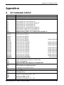
Appendices ................................................................................................................................ 91
AT Commands in Brief.................................................................................................................. 91
Technical Specifications .............................................................................................................. 95
RJ-11 Socket Pin Assignment ................................................................................................. 96
MicroLink ISDN/TL V.34 Manual ©1997 ELSA GmbH
3
Contents
C
D
E
F
G
H
I
RS-232/V.24 Interface.................................................................................................................. 98
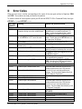
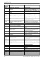
Error Codes ................................................................................................................................... 99
Answers to Frequently Asked Questions ................................................................................... 103
General Issues....................................................................................................................... 103
OS/2 Issues ........................................................................................................................... 106
Telix ....................................................................................................................................... 107
Btx / T-Online ........................................................................................................................ 107
Product Support.......................................................................................................................... 109
Glossary...................................................................................................................................... 113
Warranty Conditions .................................................................................................................. 118
Index ........................................................................................................................................... 120
4
MicroLink ISDN/TL V.34 Manual ©1997 ELSA GmbH
Introduction
1
Introduction
About this manual
This manual describes the installation, configuration and operation of the
ELSA MicroLink ISDN/TL V.34 ISDN terminal adapter.
Symbols and
conventions
The following conventions are used in this manual:
◊ NOTE ◊
denotes important information.
A filled-in box indicates a list of items:
n ...
Procedures consist of numbered steps:
1. ...
Bold text denotes the default values for AT commands and S registers.
Brackets (< >) indicate ASCII characters and characters on a keyboard. For
example, <CR> means carriage return and <BS> means backspace.
SO interface
S/T interface
In this manual, the interface between the ISDN Network Terminator (NT) and
the MicroLink ISDN/TL V.34 is referred to as the "SO interface" or "SO bus." In
the USA this interface is also known as the S/T interface.
Changes to this
manual
ELSA MicroLink ® products are subject to continual development. It is
therefore possible that slight variations between the printed documentation
and the latest release may arise. However, you will always find the latest
information in the Support BBS ELSA ONLINE, the ELSA Internet WWW site
and Compuserve (see page 109).
Package contents
Please make sure that your package contains the following items:
n
ELSA MicroLink ® ISDN/TLV.34 terminal adapter
n
External power supply (AC adapter)
n
ISDN SO line connection cable
n
RS-232/V.24 serial cable
n
9-pin to 25-pin adapter
n
Disks and/or CD-ROM with application software
n
Printed manual
If any item is missing or damaged, please contact your dealer. (ELSA reserves
the right to change package contents without prior notice.)
MicroLink ISDN/TL V.34 Manual ©1997 ELSA GmbH
5
Introduction
Notes:
6
MicroLink ISDN/TL V.34 Manual ©1997 ELSA GmbH
Brief Description
2
Brief Description
Congratulations for purchasing the MicroLink ISDN/TL V.34 terminal adapter - the most versatile ISDN
communications device available!
The MicroLink ISDN/TL V.34 integrates state-of-the-art ISDN digital technology with high-speed
analog modem and facsimile capabilities into a single, convenient desktop device. This unique
synergy makes the MicroLink ISDN/TL V.34 the perfect high-speed solution for all digital and analog
communications requirements.
n
As an ISDN device, the MicroLink ISDN/TL V.34 supports data transfer rates up to 115,200 bps
across digital communications lines. For increased data throughput, the MicroLink ISDN/TL V.34
supports V.42bis data compression for effective transfer rates up to 230,400 bps, as recognized
at the computer serial interface. This makes the MicroLink ISDN/TL V.34 ideal for access to the
Internet, corporate local-area networks, and on-line information systems.
n
As a high-speed analog modem, the MicroLink ISDN/TL V.34 adheres to the international V.34
and V.Fast standards, V.32bis, V.32, V.22bis, V.22, V.21, V.23, V.42bis and MNP5, so ensuring
worldwide compatibility with current analog modems at speeds from 300 to 33,600 bps. V.42
and MNP 4 error correction guarantee error-free, and V.42bis and MNP 5 data compression
ensure maximum data throughput. MicroLink ISDN/TLV.34 uses the V22bis and V.21 for
transfers at 300 to 2400 bps.
n
As a high-speed facsimile machine, faxes can be exchanged with Group 3 compatible facsimile
machines and fax/modems at speeds up to 14,400 bps. In addition, the MicroLink ISDN/TL V.34
supports fax polling, allowing the preparation of documents for retrieval by remote facsimile
machines.
These state-of-the-art features maximize communications activities while reducing the line charges,
resulting in significant cost savings.
The MicroLink ISDN/TL V.34 is also intelligent enough to distinguish among incoming ISDN, modem,
and fax calls and can route calls appropriately - even if your software does not support auto-detection
capabilities.
Moreover, the MicroLink ISDN/TL V.34 is compatible with the industry-standard AT command set for
trouble-free ISDN or analog communications manually (refer to page 32 for more information) or using
your preferred communications software.
ELSA MicroLink ® products are continually being improved. You will always find the latest
information about this product in the Support BBS ELSA ONLINE, the ELSA Internet WWW site and
Compuserve (see page 109).
2.1 Key Features of the MicroLink ISDN/TLV.34
The following section summarizes the key features of the MicroLink ISDN/TL V.34.
2.1.1 ISDN Features
Channel bundling
This feature allows the two 64,000 bps B (Bearer) channels of an ISDN Basic
Rate Interface to be virtually linked, doubling the effective data throughput of
MicroLink ISDN/TL V.34 Manual ©1997 ELSA GmbH
7
Brief Description
a digital connection to 128,000 bps. This process uses, provisionally, a
protocol proprietary to ELSA, so only a connection between two ELSA devices
supports this.
D channel protocols
The MicroLink ISDN/TL V.34 provides AT commands for selecting the
appropriate local D channel protocol. European models support the DSS1
(Euro-ISDN) and German 1TR6 protocols, while US models support the
National ISDN-1 protocol (NI-1) and AT&T 5ESS protocols.
PPP conversion
The Point-to-Point Protocol conversion allows the combination of
asynchronous PPP computer software with synchronous PPP-ISDN access
points, (e.g. via Routers). The conversion complies with RFC 1662.
Automatic detection
The MicroLink ISDN/TL V.34 can distinguish between incoming 56,000 and
64,000 bps ISDN calls and adjust its speed accordingly.
ISDN AT command set The MicroLink ISDN/TL V.34 is compatible with the industry-standard AT
command set, which allows control of the modem either manually (as
described in this manual) or via AT-compatible software.
Automatic cost
monitoring
The European version of the MicroLink ISDN/TL V.34 (DSS1 and 1TR6
protocols) can monitor ISDN charge information and guarantees that a userdefined number of charge units is not exceeded during a specific period of
time. This feature is not offered by the network providers in some countries.
2.1.2 Analog Features
Integrated
V.34/V.Fast modem
The MicroLink ISDN/TL V.34 provides V.34/V.Fast modem capabilities for
exchanging data with analog modems at speeds up to 33,600 bps. With
slower remote modems, the maximum possible data exchange rate will
automatically be selected.
To optimize performance:
Integrated
send/receive
facsimile machine
8
n
The MicroLink ISDN/TL V.34 supports the V.42 and MNP 4 errorcorrection protocols, ensuring error-free data transmissions - even over
noisy telephone lines - with analog modems that also support these
protocols.
n
The MicroLink ISDN/TL V.34 supports the V.42bis and MNP 5 datacompression protocols, ensuring the fastest data throughput possible
with analog modems that also support these protocols.
The MicroLink ISDN/TL V.34 provides analog facsimile capabilities for sending
faxes to and receiving them from Group 3 compatible facsimile machines and
fax/modems at speeds up to 14,400 bps. If the remote device cannot operate
at 14,400 bps, your MicroLink ISDN/TL V.34 automatically falls back to the
maximum speed supported by the remote device.
MicroLink ISDN/TL V.34 Manual ©1997 ELSA GmbH
Brief Description
2.1.3 Transfer Modes
The MicroLink ISDN/TL V.34 can automatically switch among the ITU-T V.110, ITU-T V.120, and X.75
protocols to match the protocol of, and establish a data connection with, remote systems. This section
describes these protocols and the various transfer modes that the MicroLink ISDN/TL V.34 supports.
V.110
The MicroLink ISDN/TL V.34 can operate in accordance with ITU-T V.110
(I.463), providing asynchronous transfer rates of 1200 to 38,400 bps and
synchronous transfer rates of 1200 to 64,000 bps.
V.120
The MicroLink ISDN/TL V.34 supports the international ITU-T standard V.120
(I.465) at 56,000 and 64,000 bps. This feature allows error-corrected data
connections with transfer rates up to 230,400 bps (asynchronous), and ISDN
connections with remote stations in the USA.
X.75
The MicroLink ISDN/TL V.34 supports X.75/T.70NL.
Automatic protocol
detection
Using real-time V.42bis data compression in X.75 and V.120 modes, the
MicroLink ISDN/TL V.34 can achieve an effective data throughput of up to
230,400 bps.
Bit rate adaptation
The MicroLink ISDN/TL V.34 supports V.110 bit rate detection, allowing it to
establish a data connection using the fastest speed supported by the remote
system. The MicroLink ISDN/TL V.34 can also automatically adapt the RS232/V.24 bit rate to the ISDN line transfer rate, without requiring user
intervention.
T-Online
The MicroLink ISDN/TL V.34 can access the German T-Online online service in
both VT-100 and CEPT/KIT modes using the commands AT\N8 and AT\N9
(refer to page 46).
2.1.4 Additional Features
Asynchronous
RS-232-C data port
The MicroLink ISDN/TL V.34 can be connected to the RS-232-C data serial port
of an IBM, Macintosh, or compatible personal computer. An IBM-compatible
serial cable is provided with your MicroLink ISDN/TL V.34.
Front panel status
display
Easy-to-read colored LEDs on the front panel provide information as to the
MicroLink ISDN/TL V.34 ’s status.
MSN and EAZ support With the European version of the MicroLink ISDN/TL V.34, Multiple Subscriber
Numbers (MSN, DSS1 protocol) or Terminal Selection Digits (EAZ, German
1TR6 protocol) can be assigned.
MicroLink ISDN/TL V.34 Manual ©1997 ELSA GmbH
9
Brief Description
Closed user group
support
The European version of the MicroLink ISDN/TL V.34 can automatically check
incoming telephone calls. This feature lets you restrict call acceptance to a
private user group, protecting your system against unauthorized access.
Additional
information
For added security, the European version of the MicroLink ISDN/TL V.34 can
also display the telephone number of an incoming call before establishing the
connection. In addition, connection costs can be displayed during and after a
connection. Connection Status: information about the status of the connection
can also be displayed (e.g. ALERTING).
Flash ROM
Flash ROM technology allows the quick and easy update of software, simply
by reading in the new file. The state-of-the-art is always just an update away.
230,400 bps
Using a suitable serial interface card, a line bit rate of 230,400 bps is possible.
Ringing bell
Your MicroLink ISDN/TL V.34 can alert you of incoming calls by ringing just
like a normal telephone. See register S54 (page 67).
10
MicroLink ISDN/TL V.34 Manual ©1997 ELSA GmbH
Brief Description
2.2
CE Conformity and FCC Rules
The CE seal indicates compliance with rules laid down by the European
Community on April 29, 1991 for the alignment and mutual recognition of the
member states' laws concerning telecommunications devices.
All CE approved ISDN devices may be connected to the Euro-ISDN in all EU
countries except for Germany, where an additional national approval
certificate is required.
MicroLink ISDN/TL V.34 has been approved by the BZT according to the new
European procedure and may therefore be connected to the Euro-ISDN in all
countries of the EU. MicroLink ISDN/TL V.34 therefore complies with:
n
NET 3 (ISDN Basic Rate Access)
n
Electromagnetic compatibility standards
n
Safety standards
FCC
This equipment has been tested and found to comply with limits for a Class B
computing device according to the specifications in FCC (Federal
Communications Commission) rules Part 15.
Interference
This equipment, like other electronic equipment, generates and uses radio
frequency energy. If not installed and used according to the instructions in
this manual, this equipment may cause interference to radio and television
reception.
If interference with radio or television reception is apparent, turn the modem
equipment off. If the interference problems stop, then the equipment is
probably the cause. One or more of the following may solve the problem:
n
Adjust the position of the radio or TV antenna.
n
Move the device away from the radio or TV.
n
Plug the power adapter of the device into a different outlet than the
radio or TV uses.
n
Consult the dealer or an experienced radio/TV technician for help.
If this device is malfunctioning, it may also be causing harm to the ISDN
network. This device should be disconnected until the source of the problem
can be determined and until repair has been made.
MicroLink ISDN/TL V.34 Manual ©1997 ELSA GmbH
11
Brief Description
Notes:
12
MicroLink ISDN/TL V.34 Manual ©1997 ELSA GmbH
Installation
3
Installation
This chapter describes installation of the MicroLink ISDN/TL V.34 terminal adapter.
3.1 Safety Notice
To ensure your safety and the proper operation of the MicroLink ISDN/TL V.34 and your computer
system, please observe the following guidelines:
n
Use only the original external power supply shipped with your ISDN terminal adapter.
n
Refrain from using a power supply that has been opened or mechanically damaged. Touching
the primary voltage (Europe: 230 V, USA: 120 V) with the hand or with metal parts results in an
electric shock, which can be deadly.
n
Use only the supplied ISDN SO line connection cable to connect your MicroLink ISDN/TL V.34 to
an ISDN digital communications line.
n
Do not touch the metal pins of the MicroLink ISDN/TL V.34 connection sockets. Even slight dirt
or electrostatic discharging may cause malfunctions or, in extreme cases, damage the device.
3.2 System Requirements
The following are required for the successful installation of the MicroLink ISDN/TL V.34 terminal
adapter:
n
An IBM PC or compatible computer with a 9/25-pin serial communications interface (COM port):
recommended is a 16550 (FIFO) buffered Universal Asynchronous Receiver/Transmitter (UART) to
operate at speeds up to 115,200 bps.
n
An NT-1 device (in the US only).
n
An ISDN digital communications line.
n
An available AC power outlet.
◊ NOTE ◊
MicroLink ISDN/TL V.34 can also be connected to the serial port of an Apple
Macintosh computer. This connection requires a serial cable with a 9-pin
male connector on one end (for connection to the Macintosh) and a 25-pin
male connector on the other.
MicroLink ISDN/TL V.34 Manual ©1997 ELSA GmbH
13
Installation
3.3
Installing the Terminal Adapter
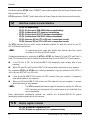
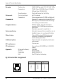
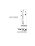
During the installation, refer to the following diagrams which show the front and back of your
MicroLink ISDN/TL V.34 .
Front panel LEDs
Back panel
connectors
No
1
2
3
4
5
Meaning
ON/OFF switch
AC power connector
Serial line connection to computer
Reset switch
ISDN line connector (S0 (S/T) bus interface)
Installation summary
The installation process involves the following steps:
1. Power supply
Connect the MicroLink ISDN/TL V.34 to an AC power outlet. See page 15.
2. Serial interface Connect the MicroLink ISDN/TL V.34 to a computer serial port. See page 15.
3. ISDN line
Connect the MicroLink ISDN/TL V.34 to an ISDN digital communications line.
See page 16.
4. Switching on
Turn on the MicroLink ISDN/TL V.34. See page 16.
14
MicroLink ISDN/TL V.34 Manual ©1997 ELSA GmbH
Installation
5. Selecting the
D channel
protocol
◊ NOTE ◊
Select the channel protocol. See page 16.
US protocols: enter DN and SPID (see page 17).
When connecting to an AC power outlet, use only the external power supply
provided with the MicroLink ISDN/TL V.34. Do not use a power supply
designed for a different device.
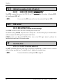
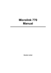
Setup diagram
ISDN
Power
Power
NT-1
V.24/RS 232C
MicroLink ISDN/TL
U-Interface
S/T or S0
Interface
PC
MicroLink ISDN/TL V.34
Connecting to an
AC power outlet
The following procedure explains how to connect the MicroLink ISDN/TL V.34
to an AC power outlet. This connection is made using the supplied external
power supply (AC adapter).
1. Verify that the voltage of the power line matches the voltage of the
supplied AC adapter.
2. Insert the supplied AC adapter cord into the power connector labeled
AC 9V~ on the MicroLink ISDN/TL V.34 back panel (see the "Back Panel
Connectors" diagram, number ℑ).
3. Insert the wall transformer on the other end of the power cord into a
grounded AC outlet.
Connecting to a
computer serial port
The MicroLink ISDN/TL V.34’s serial port connection is provided by an RS-232
25-pin D-type connector. This connector is located on the back panel of the
MicroLink ISDN/TL V.34. To make this connection:
1. If your computer is turned on, turn it off.
2. Insert the 25-pin end of the supplied RS-232/V.24 serial cable into the
serial connector on your Data Terminal Equipment.
◊ NOTE ◊
If your computer or terminal has a 9-pin serial connector, use the supplied 9to-25-pin adapter.
3. Insert the other cable end into the DTE connector labeled V.24/V.28 on the
MicroLink ISDN/TL V.34 back panel (see "Back Panel Connectors" diagram,
number ℜ).
MicroLink ISDN/TL V.34 Manual ©1997 ELSA GmbH
15
Installation
4. Use the standoffs on each end of the cable to secure the cable connector to
the DTE serial port and the MicroLink ISDN/TL V.34.
Connecting to an
ISDN line
The following procedure explains how to connect the MicroLink ISDN/TL V.34
to an ISDN digital communications line. This procedure assumes an installed
ISDN communications line is available. If not, please contact your telephone
company to obtain an ISDN line.
1. Connect your NT-1 device to your ISDN communications line. If you need
assistance, please refer to the relevant manual.
2. Insert the RJ-11 end of the supplied ISDN SO line connection cable into the
ISDN/SO connector on the back panel (see "Back Panel Connectors"
diagram, number Ä).
3. Insert the other end of the cable into the ISDN telephone wall jack.
Turning on the ISDN
terminal adapter
Use the following procedure to turn on the MicroLink ISDN/TL V.34.
1.
Turn on the MicroLink ISDN/TL V.34 with the power switch on the back
panel.
The Test- and ISDN Line LEDs flash as the
MicroLink ISDN/TL V.34 performs a brief self-test. After the tests
complete, both LEDs should go OFF.
2.
Start the communications software and configure it as follows:
n
Use a baud rate of either 230,400 bps or 115,200 bps.
n
Select the COM port to which the MicroLink ISDN/TL V.34 is
connected, e.g. COM 1 or COM 2.
For more information on performing these steps, refer to the manual for
your communications software.
3.
Enter local terminal (or "direct connect") mode. Again, refer to your
communication software manual for assistance.
4.
Type AT and press <CR>. An OK result code should be displayed on
your computer screen. If not, compare the PC-to-Terminal Adapter
connection with the "Setup" diagram.
Completing the
installation
To complete the installation, refer to the appropriate following section for
European or US models as relevant:
European models
The D channel protocol controls the exchange of signals between the local
station and the nearest ISDN exchange. The European Community uses either
of two D channel protocols:
16
n
The DSS1 channel protocol, also referred to as Euro-ISDN, used in most
European Community countries.
n
The 1TR6 channel protocol, which is primarily used in Germany.
MicroLink ISDN/TL V.34 Manual ©1997 ELSA GmbH
Installation
To ensure compatibility throughout Europe, European versions of the
MicroLink ISDN/TL V.34 support both the international DSS1 channel protocol
(Euro-ISDN) and the German 1TR6 channel protocol.
By default, the MicroLink ISDN/TL V.34 is configured for the DSS1 D-channel
protocol. If your local switch requires the 1TR6 channel protocol, type
AT+IDP=1TR6 and press <CR>.
To return the MicroLink ISDN/TL V.34 to the DSS1 channel protocol, type
AT+IDP=DSS1 and press <CR>.
If required, further settings such as MSN (page 42) can be defined.
This completes the installation procedure for European models.
US models
US versions of the MicroLink ISDN/TL V.34 require a D channel protocol, a
Directory Number (DN) and a Service Profile ID ("SPID" for short) to be defined.
The D channel protocol determines how control signals are exchanged
between the local switch and your ISDN terminal adapter.
The
MicroLink ISDN/TL V.34 supports two D channel protocols:
n
National ISDN-1
n
AT&T 5ESS Custom
By default, the MicroLink ISDN/TL V.34 is configured for the National ISDN-1
channel protocol. For the AT&T 5ESS channel protocol, type AT+IDP=AT&T
and press <CR>.
To return to the National ISDN-1 channel protocol, type AT+IDP=NI-1 and
press <CR>. (In this command, the letter following the N is an upper-case i.)
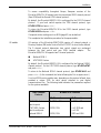
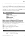
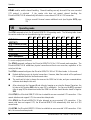
Your local ISDN service provider may, depending on the protocol offered, have
provided a unique SPID for each device attached to your digital
communications line. The following table indicates the parameters required
for the systems available:
ISDN Channel
Protocol
Number of B-Channels
1 B-Channel
2 B-Channels
AT&T 5ESS Custom,
point-to-point
No SPID or DN
No SPID or DN
AT&T 5ESS Custom,
point-to-multipoint
1 SPID, 1DN
1- or 2 SPID and
1- or 2 DN
National ISDN-1
1 SPID, 1DN
2 SPID and 2 DN
MicroLink ISDN/TL V.34 Manual ©1997 ELSA GmbH
17
Installation
For example, to enter the parameters for the National ISDN-1 protocol, 2 B
channels, the following commands must be entered:
st
AT+ISPID1=0156596200
(For the 1 B-channel)
AT+IDN1=5659620
(For the 1 B-channel)
AT+ISPID2=0156596210
(For the 2 B-channel)
AT+IDN2=5659621
(For the 2 B-channel)
st
nd
nd
No SPID is necessary for the AT&T 5ESS Custom point-to-point configuration
(so type AT+ISPID1= and AT+ISPID2=)
◊ NOTE ◊
Each SPID can only be used one at a time. Do not attempt to use one SPID
with two ISDN devices simultaneously. This will result in a malfunction!
This completes the installation procedure.
3.4 Installation under Windows 95
Installation
◊ NOTE ◊
18
To install your MicroLink ISDN/TL V.34 under Windows 95, follow the
instructions given here:
1.
Start Windows 95
2.
Switch on your MicroLink ISDN/TL V.34.
3.
From My Computer call the following menus:
4.
Control Panel, Modems
5.
Activate Don't detect modem, I will select it from a list...
6.
Click on Have Disk..., then
7.
Browse... for your floppy drive or CD-ROM drive (a:\ or d:\ respectively)
8.
Select the file MDMELSA.INF (e.g. D:\).
After copying this file the installation is complete, and the ISDN terminal
adapter MicroLink ISDN/TL V.34 is available for use. The standard software
under Windows 95 (e.g. Microsoft Exchange, HyperTerminal etc.) has direct
access to your MicroLink ISDN/TL V.34.
MicroLink ISDN/TL V.34 Manual ©1997 ELSA GmbH
Status Display and Fault Diagnosis
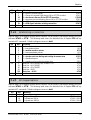
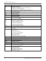
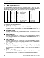
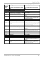
4 Status Display and Fault Diagnosis
The MicroLink ISDN/TL V.34 has 11 front panel LEDs for status display.
LED
Status
Power
ON
Status
(see Note)
OFF
FLASHING
ON
Line
OFF
Slow flash
(1 per second, 2 or 3 times)
Fast flash
(3 times per second)
ON
TxD (D1)
ON
Meaning
MicroLink ISDN/TL V.34 is turned on and receiving power.
No S0 current, S0 bus inactive.
Negotiation in process.
ISDN line active, connection to ISDN exchange1).
No incoming call or connection.
Incoming call received, but call is not suited to device.
Incoming call not yet accepted.
Connection is being established.
MicroLink ISDN/TL V.34 is receiving either data from the
remote system or a command from your computer.
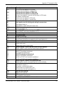
RxD (D2)
ON
MicroLink ISDN/TL V.34 is sending data to the remote
system or a result code to your computer.
DTR (S1)
ON
Terminal/computer ready for operation (see the AT&D
command on page 36).
DSR (M1)
ON
MicroLink ISDN/TL V.34 is ready for operation (see the AT\D
command on page 36).
RTS (S2)
ON
Sending device is enabled (see the AT\Q command on
page 50).
CTS (M2)
ON
MicroLink ISDN/TL V.34 is ready to send data (see the AT\D
and AT\Q commands on pages 36 and 50).
DCD (M5)
Red
Green
Orange
Test (PM1)
ON
V.110, V.100 or PPP connection established (no error correction
or fax connection).
V.120, X.75, MNP 4, MNP 5, V.42(bis) connection established
(error corrected connection).
Channel bundling is enabled.
See also the AT&C command on page 34.
MicroLink ISDN/TL V.34 is performing its self-test.
Note: Most ISDN basic rate interfaces make this LED go ON. With some PBXs, such as Siemens Hicom, the
green LED may not go ON before a connection has been established.
1)
In Europe - TEI negotiation OK
In the US - TEI negotiation OK layer 2 active, SPID negotiation OK (if SPID available)
MicroLink ISDN/TL V.34 Manual ©1997 ELSA GmbH
19
Status Display and Fault Diagnosis
Notes:
20
MicroLink ISDN/TL V.34 Manual ©1997 ELSA GmbH
Operation
5
Operation
5.1 General
This chapter describes how to operate the MicroLink ISDN/TL V.34. Topics include:
n
Communicating with the MicroLink ISDN/TL V.34
n
Operating modes
n
Typing AT commands
n
Resetting the MicroLink ISDN/TL V.34
n
Performing fax activities
n
Performing voice activities
5.2 Communicating with the Terminal Adapter
After installing and configuring the MicroLink ISDN/TL V.34, communication activities can be
controlled using either the supplied communications software program or another program compatible
with the AT command set. There are two ways to communicate with your MicroLink ISDN/TL V.34:
n
Indirectly, using the commands in your communications software program, or
n
Directly, using AT commands.
Indirect method
The indirect method involves the use of commands and menus in suitable
communications software programs. The user’s input via an intuitive interface
is converted into the appropriate AT command(s) for issue to the
MicroLink ISDN/TL V.34. Thus communication with your device is possible
without prior knowledge of the AT command set.
Refer to the program manual for instructions on performing these tasks.
Direct method
With the direct method, your communications software should be in local
terminal (or "direct connect") mode. AT commands can thus be typed in
directly.
Before typing AT commands, the MicroLink ISDN/TL V.34 must be in Command
Mode (described in the next section). Entering AT commands is described on
page 22. A complete description of the AT commands supported by the
MicroLink ISDN/TL V.34 begins on page 32.
5.3 Operating Modes
The MicroLink ISDN/TL V.34 has two operating modes: Command Mode and Online Mode.
When using a software interface to communicate indirectly with the modem, these modes will not be
apparent to the user.
To use the direct method, the MicroLink ISDN/TL V.34 must be in Command Mode before typing AT
commands. This is described in the next section.
MicroLink ISDN/TL V.34 Manual ©1997 ELSA GmbH
21
Operation
5.3.1 Command Mode
In Command Mode, the AT commands as entered control the MicroLink ISDN/TL V.34 to perform
activities such as dialing or answering a call. The MicroLink ISDN/TL V.34 automatically defaults to
Command Mode in the following cases:
n
When it is turned on.
n
When it disconnects from a connection.
n
If any key on your computer keyboard is touched while during dialing.
n
After the MicroLink ISDN/TL V.34 is reset, using either the Reset button (described on page 25)
or the ATZ command (described on page 55).
5.3.2 Online Mode
The MicroLink ISDN/TL V.34 automatically enters Online Mode when it makes a data- or fax
connection with a remote modem, fax or ISDN device. Data exchange takes place in this mode.
Commands cannot be entered in Online Mode. Typed entries will be treated as data and sent to the
remote device. To send commands the mode must be switched as described in the next section.
5.3.3 Switching Between Modes
The situation may arise when a switch from Online Mode to Command Mode is desirable, e.g. to
change a register value during a data transfer.
Using the Escape Characters (default value: +++), you can switch from Online Mode to Command
Mode while preserving the data connection with the remote modem. The Escape Characters can be
changed using the Register S2.
The Escape Characters do not require the prefix AT or the suffix <CR>. A pause is required before
and after typing the Escape Characters. The number of seconds to wait is defined by Register S12.
The default wait time is one second.
The following example shows how to use the Escape Characters:
1.
After making a data connection with a remote device, wait at least one second.
2.
Type the Escape Character three times (for example, +++) and wait at least one second.
3.
The MicroLink ISDN/TL V.34 enters Command Mode, and an OK result code is displayed. The
desired AT commands can then be entered.
4.
To return to Online Mode, type ATO and press <CR>. A CONNECT result code is displayed.
5.
To hang up at the end of the data connection, type ATH and press <CR>.
22
MicroLink ISDN/TL V.34 Manual ©1997 ELSA GmbH
Operation
5.4
Entering AT Commands
AT commands are entered in a command line which can contain one or more AT commands. Enter a
command line as follows:
1.
Make sure your MicroLink ISDN/TL V.34 is in Command Mode (refer to page 21).
2.
Type the AT characters. These characters must be entered at the start of each new command
line. These characters provide the MicroLink ISDN/TL V.34 with the serial port transmission
speed, character length and parity settings used by your computer.
◊ NOTE ◊
Both AT characters must be typed in the same case. Do not type At or aT.
3.
Type one or more commands. A command line can contain a maximum of 255 characters,
including AT.
4.
Press <CR>. The MicroLink ISDN/TL V.34 sends an OK result code and performs the task(s).
◊ NOTE ◊
If you receive ERROR instead of OK, the command line, or a part of it, was
not executed. Check for errors in the command line entered.
The following example shows a series of AT commands. Each command line starts with AT and has
an OK result code below it.
at\n3
Command input in
several command lines OK
at\v8
OK
ats0?
000
OK
These commands can be entered in sequence in a single command line:
Command input in
one command line
at \n3 \v8 s0?
000
OK
For better legibility, the individual commands can be separated by blank
spaces.
Observe the following guidelines when typing AT commands:
Correcting a typing
mistake
If you make a mistake when typing an AT command, press the Backspace
<BS> key to delete the error. You can delete every character on a command
line except AT.
Enhancing readability To enhance readability, you can include spaces and punctuation marks such as
parentheses and hyphens in your command line. For example:
ATD 1 (513) 555-1212
MicroLink ISDN/TL V.34 Manual ©1997 ELSA GmbH
23
Operation
Spaces and punctuation marks have no effect on command execution, but they
do count toward the 255-character maximum.
Omitting a parameter
Some AT commands require a numeric parameter such as 0 or 1. Omitting this
parameter results in the default value of 0 being used. The ATV command, for
example, requires a parameter of 0 to enable numeric result codes or 1 to
enable word result codes. If you type ATV but fail to include a 0 or 1, the V0
command is assumed, enabling numeric result codes.
Including other
commands
If your command line includes a Dial- (ATD) or Reset command (ATZ), any
other accompanying commands should be in front of the ATD or ATZ
command. For example:
AT M3 X5 V1 D 1 513 555 1212
Re-executing a
command line
To repeat the last command line executed, type A/ while omitting AT in front
of it and <CR> afterward. This command is convenient, for example, if the
last number called was busy. Typing A/ lets you automatically redial the call
without retyping the command line.
◊ NOTE ◊
Resetting your MicroLink ISDN/TL V.34 or turning it off and on removes the
last-executed command from memory, invalidating the A/ command.
Independent line speed The bit rate your computer uses to communicate with the
MicroLink ISDN/TL V.34 is called the Data Terminal Equipment (DTE) rate or
serial port bit rate. The speed your MicroLink ISDN/TL V.34 uses to transmit
data is called the Data Communications Equipment (DCE) rate or DCE line
speed.
By default, the DCE rate is determined by the DTE rate. If, for example, your
computer sends an AT command line at 19,200 bps to your
MicroLink ISDN/TL V.34, the MicroLink ISDN/TL V.34 will use a full-duplex DCE
rate of 19,200 bps.
The AT&G1 and AT%B commands can be used to select a DCE rate for your
MicroLink ISDN/TL V.34, independent of your computer’s serial port speed.
For example, you can set the DCE rate to a fixed 38,400 bps while the DTE rate
remains at 19,200 bps.
If you want to return your MicroLink ISDN/TL V.34 to using the DTE rate, issue
the AT&G0 command.
ISDN connections with a V.120 or X.75 protocol will always use 64,000 bps or
56,000 bps (see %S AT-command, page 52).
24
MicroLink ISDN/TL V.34 Manual ©1997 ELSA GmbH
Operation
5.5
Resetting the Terminal Adapter
There are two methods for resetting the MicroLink ISDN/TL V.34:
n
A hardware method, using the Reset button on the back of your MicroLink ISDN/TL V.34.
n
A software method, using the ATZ or the AT&F commands.
Both methods are described in the following sections.
Hardware reset
method
The back panel of the MicroLink ISDN/TL V.34 has a Reset button to
reinitialize the ISDN modem. Facing the back panel, you can find the Reset
button between the V.24/V.28 and ISDN/SO connectors (see "Back Panel
Connectors" diagram, number ℘, page 14).
When the MicroLink ISDN/TL V.34 is configured for dumb mode (refer to page
38),using the Reset button returns it to normal operation.
The Reset button is recessed to prevent accidental resets. If you want to
press the Reset button, do so using a narrow object, such as a pencil.
If you press the Reset button, the following results:
Software reset
method
n
Any data connection with a remote modem is ended.
n
The MicroLink ISDN/TL V.34 reinitializes itself and performs a self-test.
n
All serial ports are cleared of data.
n
The last-executed command is lost from memory, invalidating the A/
command until your MicroLink ISDN/TL V.34 executes a command.
n
The configuration profile is loaded (either the default values or the user
values as defined with the commands AT&W or AT*W).
n
The MicroLink ISDN/TL V.34 enters Command Mode.
n
Keeping the reset button pressed for a longer time restores the factory
defaults.
The ATZ or AT&F command resets the MicroLink ISDN/TL V.34. Just type
ATZ (or AT&F) and press <CR>.
MicroLink ISDN/TL V.34 Manual ©1997 ELSA GmbH
25
Operation
5.6
Channel Bundling
Channel bundling allows the two B (data) channels of an ISDN Basic Rate Interface to be bundled into
a single, high-speed logical connection. Under ideal conditions, channel bundling doubles the
effective data throughput of the ISDN connection. Realized performance gains, however, depend on
the type of data transferred.
If channel bundling is enabled (AT&N1, refer to page 45), large amounts of data are distributed
equally to both B channels. While channel bundling is active, the DCD (M5) orange LED on the front
panel lights up.
Channel bundling increases line charges because two B channels are used. If desired, Bit 6 of
Register S175 can be set to adapt the establishment of the secondary connection to the ISDN charge
information (see page 78).
The MicroLink ISDN/TL V.34 supports two types of channel bundling: static bundling and dynamic
bundling. The settings of register S175 enable either of these channel bundling methods (refer to
page 78).
Static channel
bundling
With this method, the second B channel connection is established as soon as
the first (primary) connection is made. The secondary connection remains
active until the primary connection ends.
If the secondary connection cannot be established (or is refused) within 30
seconds, the called side cancels the primary connection (see Register S175).
The CONNECT result code does not appear until the secondary connection is
established.
If the secondary connection fails (for example, if the network is busy), the
calling side tells the answering side that the second B channel will not be
used and establishes a one-channel connection with 64,000 bps or 56,000 bps
instead.
Dynamic channel
bundling
With this method, the secondary connection is established when the
throughput limit defined in Registers S176 and S177 is reached (refer to page
79). If a secondary connection establishment fails, it retries the connection
every 15 seconds, as long as the reason for the secondary connection is valid.
To use your MicroLink ISDN/TL V.34 in the US, please observe the programming of SPID and DN
configurations, as explained under in the US Models section of the Installation chapter (see page 17).
26
MicroLink ISDN/TL V.34 Manual ©1997 ELSA GmbH
Operation
5.7
Fax Operation
The MicroLink ISDN/TL V.34 can send faxes to and receive faxes from conventional analog fax
machines. The software supplied is capable of convenient faxing at speeds from 2400 bps up to
14,400 bps half-duplex , in V.17, V.33, V.29 or V.27ter mode.
5.7.1 Fax Command Sets
The following sections describe the fax command set compatibility.
Class 2/Class 2.0
The MicroLink ISDN/TL V.34 complies with the fax command set TR-29.2
Class 2 (SP-2388) and TR-29.2 Class 2.0 (TIA/EIA-592) lets you use any
standard fax software, such as WinFax or Bitfax. A brief description of the TR29.2 Class 2 and Class 2.0 fax commands supported by the ELSA MicroLink®
modems is available in the MODEMS forum file area of the ELSA ONLINE
Support BBS (see the telephone number on page 57).
Class 1
The MicroLink ISDN/TL V.34 supports the fax command set Class 1 (TIA/EIA578). This support is required for E-mail functions using Microsoft Windows
for Workgroups and the file transfer function of WinFax PRO 4.0. For a brief
description of the Class 1 fax commands supported by the
MicroLink ISDN/TL V.34, access the MODEMS forum file area of the ELSA
ONLINE Support BBS (see the telephone number on page 57).
5.7.2 Data Flow in Fax Operation
By default your MicroLink ISDN/TL V.34 can use both hardware and software handshaking
simultaneously during fax Class 1 and Class 2 mode. As soon as a certain handshake method is
selected with AT\Q, only that method is used.
5.7.3 Adaptive Answer
This feature automatically differentiates between incoming fax and data calls. The fax software in
use must also support adaptive answer.
Set up your fax software to start when the MicroLink ISDN/TL V.34 receives "+FDM" or "DATA." If the
fax software sends an initialization string, set Register S14, bit 6 to 1 (refer to page 60). This prevents
the MicroLink ISDN/TL V.34 from hanging up.
The following fax commands support adaptive answer:
Class 2.0
Modem initialization:
AT+FCLASS=2.0
Enter Class 2.0 fax mode
AT+FAA=1
Set adaptive answer mode
(fax/data auto mode)
AT+FCR=1
Enable fax receiving
AT+FIS=5
Set V.17, followed by other settings as necessary
MicroLink ISDN/TL V.34 Manual ©1997 ELSA GmbH
27
Operation
Result codes for incoming fax call:
RING
Incoming call
+FCO
Fax connect result code
Result codes for incoming data call:
RING
Incoming call
+FDM
Detection of data calling tone (1300 Hz)
CONNECT
Data connect result code
Class 2
Modem initialization:
AT+FCLASS=2
Enter Class 2 fax mode
AT+FAA=1
Set adaptive answer mode
(fax/data auto mode)
AT+FCR=1
Enable fax receiving
AT+FDIS=,5
Set V.17, followed by other settings,
if necessary
Result codes for incoming fax call:
RING
Incoming call
FAX
Detection of fax calling tone (1100 Hz)
+FCON
Fax connect result code
Class 1
Result codes for incoming data call:
RING
Incoming call
DATA
Detection of data calling tone (1300 Hz)
CONNECT
Data connect result code
Modem initialization:
AT+FCLASS=1
Enter Class 1 fax mode
AT+FAE=1
Set adaptive answer mode (fax/data auto mode) Other
settings, if necessary
Result codes for incoming fax call:
RING
Incoming call
FAX
Detection of fax calling tone (1100 Hz)
CONNECT
Fax connect result code
Result codes for incoming data call:
RING
Incoming call
DATA
Detection of data calling tone (1300 Hz)
CONNECT
Data connect result code
◊ NOTE ◊
28
For fax Class 2 and Class 1, if the MicroLink ISDN/TL V.34 receives a RING
result code directly after the AT+FCLASS=2 or AT+FCLASS=1 command, it
sends the result code at 19,200 bps. If another AT command is sent instead,
your MicroLink ISDN/TL V.34 returns to using the bit rate at which the AT
command was sent.
MicroLink ISDN/TL V.34 Manual ©1997 ELSA GmbH
Operation
5.8
Voice Operation
The MicroLink ISDN/TL V.34 provides voice functions that, in connection with the supplied voice
software and a PC soundcard, enable the use your MicroLink ISDN/TL V.34 as an answering machine.
For more information on performing voice activities, refer to the voice software documentation.
To obtain a detailed description of the voice commands that the MicroLink ISDN/TL V.34 supports, call
the ELSA ONLINE Support BBS.
If, on replay, the voice files sound distorted, the byte order of the voice data may be reversed. Such
reversals occur when voice files are recorded using older recording methods. To resolve this problem,
refer to Register S229 on page 81. See also Register S230, page 83.
5.9
Dialing and Answering Calls
This chapter describes how to use AT commands to dial and answer calls. If you will be using the
commands in your communications software program to originate and answer calls, this chapter can
be skipped.
5.9.1 Originating a Call
To originate a call:
1.
Type AT D telephone number , where telephone number
MicroLink ISDN/TL V.34 is to dial.
2.
Press <CR>.
is the number the
A typical Dial command line might look like:
AT D 1 213 555-1212
The data connection between your MicroLink ISDN/TL V.34 and the remote device ends when any of
the following occurs:
n
The MicroLink ISDN/TL V.34 loses the carrier signal from the remote modem.
n
You return to the command mode, type ATH and press <CR> to hang up.
n
The MicroLink ISDN/TL V.34 detects the drop of the Data Terminal Ready (DTR) interface signal
with the &D2 or &D3 command in effect.
The MicroLink ISDN/TL V.34 then hangs up, returns to the Command Mode, and displays the NO
CARRIER result code.
◊ NOTE ◊
If the dialing attempt results in a busy signal, you can type ATDL and press
<CR> to redial the last telephone number dialed, or type A/ without pressing
<CR> to execute the entire command line again.
MicroLink ISDN/TL V.34 Manual ©1997 ELSA GmbH
29
Operation
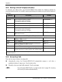
5.9.2 Dialing a Stored Telephone Number
To automate your dialing tasks, your MicroLink ISDN/TL V.34 provides the following methods for
storing telephone numbers in nonvolatile memory and dialing the numbers using the fewest number of
keystrokes.
Command
Description
Example
Commands for Storing Telephone Numbers
AT&Zm=n
Store 10 telephone numbers in memory.
m = the memory location (0 through 9).
n = a telephone number (up to 36 digits).
AT&Z2=5552345<CR>
AT&Z=n
Store telephone number n in memory location 0.
AT&Z=5551212 <CR>
AT\Pn
Store telephone number n in memory location 0.
AT\P=5552424 <CR>
AT\Pmn
Store 10 telephone numbers in memory.
m = the memory location (0 through 9).
n = a telephone number (up to 36 digits).
AT\P4=5558096 <CR>
ATDn;
Store the telephone number n preceding the semicolon (;). Use
ATO to dial the number.
ATD5554321; <CR>
Commands for Dialing Stored Telephone Numbers
ATDS=m
Dial the number in memory location m that was stored using the
AT&Z=n or AT\Pn command.
ATDS=6 <CR>
ATD/m
Same as ATDS=m.
ATD/7 <CR>
ATDS
Dial the number in memory location 0 that was stored using the
AT&Zm=n, AT&Z=n, or AT\Pn command.
ATDS <CR>
ATD/
Same as ATDS.
ATD/ <CR>
ATO
Dial the number stored with the ATDn; command. Type this
ATO <CR>
command when there is no data connection with a remote modem.
If you try to store a new telephone number in a memory location that already has a stored number, the new number
overwrites the old one.
5.9.3 Answering Calls
There are two ways to answer incoming calls:
n
Automatically, where the MicroLink ISDN/TL V.34 automatically answers a call after a
predefined number of rings occurs. See the next section.
n
Manually, where you type the A command. See the next page.
◊ NOTE ◊
30
If the MicroLink ISDN/TL V.34 is in dumb mode (refer to page 38), incoming
calls can only be answered automatically.
MicroLink ISDN/TL V.34 Manual ©1997 ELSA GmbH
Operation
Automatically
answering calls
Register S0 controls the automatic answering feature. This register has a
range between 0 and 255. Its default value of 0 disables automatic
answering.
To enable automatic answering, use the following procedure to set Register
S0 to a value between 1 and 255:
1.
Type ATS0=n, where n is a number from 1 to 255 that corresponds to
the number of rings that must occur before the MicroLink ISDN/TL V.34
automatically answers the call. For example, to automatically answer
calls after the second ring, type AT S0=2.
2.
Press <CR>. The MicroLink ISDN/TL V.34 responds with OK and enables
automatic answering.
Automatic answering stays in effect for as long as the MicroLink ISDN/TL V.34
is turned on. Resetting it or turning it off returns Register S0 to the setting
specified in nonvolatile memory.
To turn off the automatic answer feature, type AT S0=0 and press <CR>. The
value of Register S0 returns to 0, disabling automatic answering.
To permanently enable automatic answering, use the AT&Wn command to
store the automatic answer setting in nonvolatile memory. For example:
n
ATS0=2&W0 sets auto-answering to configuration profile 1.
n
ATS0=2&W1 sets auto-answering to configuration profile 2.
For more information on the AT&W command, refer to page 54.
Manually answering
calls
When the automatic answer feature is not in use, incoming calls can be
manually answered with the ATA command.
Should you receive an incoming call, just type ATA and press <CR>. Your
MicroLink ISDN/TL V.34:
n
Goes off-hook.
n
Answers the incoming call.
n
Establishes a connection with the remote ISDN device.
n
Enters the Online Mode.
MicroLink ISDN/TL V.34 Manual ©1997 ELSA GmbH
31
Operation
5.10 AT Commands in Detail
Command entry
All commands given to the modem must begin with the ASCII characters AT
or at (At or aT are not valid) and end with <CR> (Carriage Return).
Exception
The only exception is the command A/, which repeats the last command line.
This command is entered without AT and must not be followed by <CR>.
Abort command
A command line or screen output (such as display of the register contents with
AT%R) can be aborted with <Ctrl><X> or <Ctrl><C>.
Parameters
Commands which require an additional parameter may also be entered
without the parameter. A missing parameter is regarded as parameter 0 (e.g.
ATE = ATE0).
Identification of the
default configuration
Parameter settings that apply to the default configuration of the ISDN terminal
adapter, as set at the factory, are marked by the symbol *.
A/
Repeat the last command
AT/
This command repeats the last entered command.
◊ NOTE ◊
A
This command is used without the AT prefix, and should not be followed by
<CR>.
Answer incoming call
ATA
This command is for Answering incoming calls by entering ATA and <CR>.
The
MicroLink ISDN/TL V.34 notifies you of incoming calls with the RING (verbose) or 2 (numeric) result
code. (Further information to establishing a connection is to be found under registers S154/S155, see
page 72 and S160, page 74.
◊ NOTE ◊
If Register S0 is set to a value other than zero, enabling automatic answering,
using the ATA command disconnects the telephone line if bit 6 of Register
S14 is set to its default setting of 0. Changing this register value to 1,
however, will not disconnect the line; this setting allows your computer to
transmit characters to the your MicroLink ISDN/TL V.34 while the connection
is being established.
Please note that registers S151 " D-channel protocol configuration" and S152 "Call indication delay"
are relevant here. Commands following ATA in the command line will not be executed. To include
additional commands on the same command line with the A command, have them follow AT and
precede A.
32
MicroLink ISDN/TL V.34 Manual ©1997 ELSA GmbH
Operation
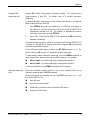
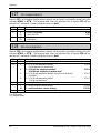
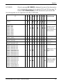
B
Predefinition of Transfer Type
The ATB command lets you specify whether your MicroLink ISDN/TL V.34 establishes a digital (ISDN)
or analog (modem) connection. The following table shows the type of connection your
MicroLink ISDN/TL V.34 will establish for outgoing and incoming calls when various ATB commands
are in effect.
Command
ATB16
ATB17
ATB18
ATB20
ATB21
ATB22
ATB24
ATB25
Outgoing
digital
digital
digital
analog
analog
analog
First digital. If not possible,
then analog
Incoming
digital
analog
digital + digital
analog
analog
digital + digital
analog
analog
ATB26
*
digital +
analog
If the ATB17, ATB18, ATB21, ATB22, ATB25 or ATB26 command is in effect, your
MicroLink ISDN/TL V.34 accepts all calls with the bearer capabilities "telephone call" or "a/b"
services." If the ATB24, ATB25, or ATB26 command is in effect, your MicroLink ISDN/TL V.34 tries to
a digital connection first. If this connection is not possible, your MicroLink ISDN/TL V.34 tries to
establish an analog connection.
The ATB command works independently of the ATDI and ATDN commands. This means you can use
the ATDIn command, for example, to dial an ISDN telephone number (specified by n) when the ATB21
command is in effect.
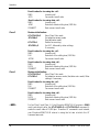
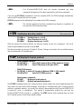
%B
ISDN line bit rate in V.110 mode
AT%B300 :
AT%B1200 :
AT%B2400 :
AT%B4800 :
AT%B7200 :
AT%B9600 :
AT%B12000 :
AT%B14400 :
AT%B16800 :
AT%B19200 :
AT%B21600 :
AT%B24000 :
AT%B26400 :
AT%B28800 :
AT%B31200 :
AT%B33600 :
* AT%B38400 :
300 bps
1200 bps
2400 bps
4800 bps
7200 bps
9600 bps
12,000 bps
14,400 bps
16,800 bps
19,200 bps
21,600 bps
24,000 bps
26,400 bps
28,800 bps
31,200 bps
33,600 bps
38,400 bps
(modem operation only)
(modem operation only)
(modem operation only)
(modem operation only)
(modem operation only)
(modem operation only)
(modem operation only)
(modem operation only)
(modem operation only)
(modem operation only)
(modem operation only)
(ISDN operation only)
MicroLink ISDN/TL V.34 Manual ©1997 ELSA GmbH
33
Operation
When your MicroLink ISDN/TL V.34 is in V.110 mode, and the AT&G1 command is in effect, you can
use the AT%B command to set the desired ISDN line bit rate, in bits per second (bps). By default, the
AT%G0 command is in effect, which sets the line rate to the serial port rate.
◊ NOTE ◊
%C
V.120 and X.75 operation ignore this command and always use a bit rate of
64,000 bps or 56,000 bps.
Data compression
AT%C0 : Disable data compression
AT%C1 : Enable V.42bis data compression
AT%C2 : Enable V.42bis data compression
* AT%C3 : Enable V.42bis data compression
This command enables or disables V.42bis data compression during an error-corrected connection in
X.75 or V.120 mode. This command works with the AT\N command, which determines your
MicroLink ISDN/TL V.34’s operating mode (refer to page 46).
The default setting, AT%C3, enables V.42bis data compression. If this compression method is not
supported by the remote modem, your MicroLink ISDN/TL V.34 attempts to establish a connection
without data compression, regardless of the AT%C command in effect.
If you desire, you can use the AT%C0 command to disable data compression.
&C
DCD option
AT&C0 : DCD is always active
* AT&C1 : DCD indicates a connection
AT&C2 : DCD is dropped during disconnection only
This command controls the Data Carrier Detect (DCD) signal. The proper use of this command depends
largely on your communications software.
AT&C0 forces the DCD signal active (ON) continuously. If your communication software requires the
DCD signal to be ON at all times, use this setting.
The default setting, AT&C1 forces the DCD signal to follow the state of the data carrier from the
remote modem.
AT&C2 drops the DCD signal when a data connection ends.
D
Connection establishment
ATDn
34
MicroLink ISDN/TL V.34 Manual ©1997 ELSA GmbH
Operation
This command tells your MicroLink ISDN/TL V.34 to dial the numbers and any special characters that
follow D in the command line. You can type up to 36 numbers or any of the following special
characters after the D. When you execute a command line that contains the D command, you can
cancel dialing by pressing any key on your keyboard (except the space bar).
Your MicroLink ISDN/TL V.34 does not execute commands that follow D in the command line. To
include additional commands on the same command line with the D command, have them precede the
D command
The special characters for dialing stored numbers must come immediately after the command ATD.
The special characters I, N and * can be entered at any position.
◊ NOTE ◊
The MicroLink ISDN/TLV.34 recognizes the type of call being made (e.g. ISDN,
modem, fax or voice) and automatically switches to the necessary mode of
operation.
Character
S or /
Meaning
Dial the number stored in nonvolatile memory location 0 using the AT&Z or AT\P
command. Example: ATDS <CR>
S=n or /n
Dial the number stored in nonvolatile memory location n using the AT\P
command. Example: ATS/0 <CR>
Redial the last number. Example: ATDL <CR>
L
In nonvolatile memory, store the digits preceding the semicolon and dial them
;
when an ATO command is executed without a data connection *)
Phone number component (e.g. for controlling PBX systems)
*
1TR6 protocol: Dialing code for external calls (valid for some private ISDN branch
#
exchanges).
DSS1 protocol: "Sending Complete" (additional information, required for dialing in
some European countries).
Establish an ISDN connection
I
Establish a modem connection
N
*) If ATO is entered several times in succession, all the digits (up to 36) are concatenated. An ATH
command or an attempt to establish a connection clears the entire string of digits.
$D
Automatic dialing with DTR
* AT$D0 : Disable DTR dialing
AT$D1 : Enable DTR dialing
The default setting, AT$D0, disables Data Terminal Ready (DTR) dialing.
If you use the AT$D1 command to enable DTR dialing, and an OFF-to-ON DTR transition occurs, your
MicroLink ISDN/TL V.34 automatically dials the number stored in memory position 0 with the AT\P or
AT&Z command (refer to pages 48 and 56). If no number is stored in position 0, your
MicroLink ISDN/TL V.34 returns an ERROR result code.
MicroLink ISDN/TL V.34 Manual ©1997 ELSA GmbH
35
Operation
&D
DTR control
AT&Dn (n = 0 to 3; default = 2)
These commands determine how the MicroLink ISDN/TL V.34 reacts to an ON-to-OFF DTR transition.
The action taken depends on the MicroLink ISDN/TL V.34’s current operating mode. The following
tables show the action taken when the parameter n equals a particular value and the
MicroLink ISDN/TL V.34 is in a particular operating mode.
In Command Mode:
n
0
1
2
This Action Occurs...
No effect.
No effect.
An existing connection ends and digits stored with ATDn are cleared.
3
Same as 2, but MicroLink ISDN/TL V.34 reinitializes (see AT&Y on page 55).
While a connection is being established, the following apply:
n
0
1
2
3
This Action Occurs...
No effect.
Connection establishment aborts.
Same as 1.
Same as 1, but MicroLink ISDN/TL V.34 reinitializes (see AT&Y on page 55).
During an existing connection:
n
0
1
2
3
This Action Occurs...
No effect.
MicroLink ISDN/TL V.34 enters the Command Mode.
Connection ends and MicroLink ISDN/TL V.34 enters the Command Mode.
Same as 2, but MicroLink ISDN/TL V.34 reinitializes (see AT&Y on page 55).
If the AT&D2 or AT&D3 command is in effect, an ON-to-OFF DTR transition prevents the
MicroLink ISDN/TL V.34 from accepting calls until DTR goes ON. While DTR is OFF, the remote side
receives a "remote station out of order" message.
\D
DSR/CTS control
* AT\D0 : DSR and CTS always ON
AT\D1 : DSR shows B channel switched through, CTS always ON
AT\D2 : DSR always ON, CTS follows DCD
AT\D3 : DSR shows B channel switched through, CTS follows DCD
This command affects the Data Set Ready (DSR) and Clear To Send (CTS) interface lines.
If hardware data flow control is enabled (AT\Q2 or AT\Q3 command is in effect), this command setting
is meaningless for the CTS interface line.
36
MicroLink ISDN/TL V.34 Manual ©1997 ELSA GmbH
Operation
E
Command echo
ATE0
* ATE1
:
:
Disable command echo
Enable command echo
The ATE command determines whether your MicroLink ISDN/TL V.34 echoes the commands you type
from your keyboard during Command Mode.
%E
Automatic retrain
AT%E0 :
* AT%E1 :
(Modem operation only)
Disable automatic retrain
Enable automatic retrain
The AT%E command controls whether your MicroLink ISDN/TL V.34 automatically initiates a retrain
when the line quality deteriorates below a certain threshold that may affect data reliability.
AT%E0 does not allows your MicroLink ISDN/TL V.34 to perform a retrain if the telephone-line quality
is poor.
The default setting, AT%E1, allows your MicroLink ISDN/TL V.34 to automatically perform a retrain
when necessary and adapt to changes in the telephone-line quality.
&F
Restore factory configuration
AT&F
This command loads the MicroLink ISDN/TL V.34’s factory default settings, returning your ISDN
terminal adapter to its original operating parameters. This command does not reset the stored
numbers, cost statistics, configuration profiles, the ISDN settings or the serial port bit rate (DTE).
◊ NOTE ◊
\F
If a data connection exists with a remote
MicroLink ISDN/TL V.34 does not execute this command .
modem,
your
Display stored numbers
AT\F
This command displays the ISDN numbers stored with the AT\P and AT&Z commands (refer to pages
48 and 56).
%G
Line bit rate control
MicroLink ISDN/TL V.34 Manual ©1997 ELSA GmbH
37
Operation
* AT%G0 : Line bit rate determined by serial port rate
AT%G1 : Line bit rate set with AT%B
The default setting, AT%G0, sets the ISDN line bit rate to the computer’s serial port bit rate during
V.110 operation. The AT characters on the command line tell your MicroLink ISDN/TL V.34 to use the
same speed and mode as the serial port.
◊ NOTE ◊
During X.75 or V.120 operation, this command is ignored and the ISDN bit rate
remains fixed at 56,000 bps or 64,000 bps.
AT%G1 lets you use the AT%B command (described on page 33) to set the ISDN line bit rate to a
speed independent of the serial port bit rate.
&G
Set calling tone and guard tone
* AT&G0 : Enable calling tone, disable guard tone
AT&G1 : Enable calling tone, enable 550 Hz guard tone
AT&G2 : Enable calling tone and 800 Hz guard tone (default UK )
AT&G4 : Disable calling tone and guard tone (default USA )
AT&G5 : Disable calling tone, enable 550 Hz guard tone
AT&G6 : Disable calling tone, enable 1800 Hz guard tone
The AT&G command enables or disables the calling tone and guard tone:
n
The calling tone is a periodic tone transmitted between the dialing and connection phases. This
tone can lead to disturbances with some foreign modems, and should be disabled in these
cases.
n
The guard tone is an additional signal sent over the telephone line in V.22bis mode.
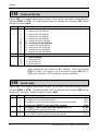
H
Hang up
ATH
ATH places your MicroLink ISDN/TL V.34 on-hook. If you switch from Online Mode to Command Mode
(using Escape Characters or an ON-to-OFF DTR transition with the AT&D1 command in effect), you can
use ATH to hang up and end the current connection.
-H
Dumb mode
* AT-H0 :
AT-H1 :
Normal operation
Dumb mode
The default setting, AT-H0, disables dumb mode.
AT-H1 enables dumb mode. In this mode:
38
MicroLink ISDN/TL V.34 Manual ©1997 ELSA GmbH
Operation
n
All commands except ATD are ignored. (You use ATD to dial a number so that a connection can
be made.)
n
Result codes are suppressed.
Because all commands except ATD are ignored, you cannot use the ATA command to answer an
incoming call. Instead, set Register S0 to a value other than zero. Dumb mode also prevents you from
using ATH to hang up a call; the call must be terminated by the remote modem. Handshaking,
however, remains active in dumb mode.
To keep the dumb mode setting valid after turning the MicroLink ISDN/TL V.34 off and on or resetting
it, add the &W command to the dumb mode command line (for example: AT-H1&W); to exit dumb
mode, hold down the Reset button on the MicroLink ISDN/TL V.34 back panel.
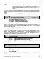
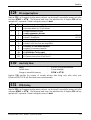
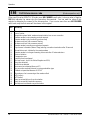
I
Display product information
ATI0 : Display model number in nnn format
ATI1 : Display checksum
ATI2 : Display checksum result (OK or ERROR)
ATI3 : Display firmware version and release date
ATI4 : Display current parameter settings
ATI5 : Display serial number
ATI6 : Display product name and hardware release
ATI9 : Display the Plug&Play ID text.
The ATI command requests information from your MicroLink ISDN/TL V.34.
ATI0 returns a three-digit ASCII string type number corresponding to the modem product code.
ATI1 returns a three-digit ASCII number corresponding to the checksum of the firmware ROM.
ATI2 calculates the checksum of the ROM and compares it with the checksum stored in the ROM. If
both values are identical, OK is returned. Otherwise, ERROR is returned.
ATI3 returns the firmware version number and the firmware date. This command corresponds to the
AT%V command.
ATI4 returns the current MicroLink ISDN/TL V.34 configuration.
ATI5 returns the MicroLink ISDN/TL V.34’s internal factory serial number.
ATI6 returns the MicroLink ISDN/TL V.34’s product name.
ATI9 returns the Plug&Play information text.
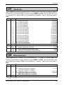
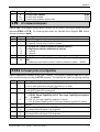
+ICLD Store numbers for closed user groups
AT+ICLDn=s : Store the number n (n = 1 to 3)
AT+ICLDn= : Clear the number n (n = 1 to 3)
AT+ICLD?
: Clear stored numbers (n = 1 to 3)
MicroLink ISDN/TL V.34 Manual ©1997 ELSA GmbH
39
Operation
The AT+ICLD command lets you restrict call acceptance to systems that have one of the three
telephone numbers you specify with this command.
Using this command, you can store in nonvolatile memory up to three numbers of remote systems
allowed access to your system. Each number can contain 16 digits (0 through 9). Because the
numbers are stored in nonvolatile memory, they are preserved when the MicroLink ISDN/TL V.34 is
turned off, reset, or reinitialized. The numbers are automatically recalled the next time the
MicroLink ISDN/TL V.34 is turned on.
When you store at least one number stored in the closed user group list and an incoming call is
received, the call is reported, but only accepted if the number of the remote system is in the closed
user group list.
If no number is in the closed user group list, all calls are reported. If the Bearer Capability and MSN
(DSS1 Multiple Subscriber Number), EAZ (1TR6 terminal selection digit) or DN (US protocol) are valid,
the call is accepted.
◊ NOTE ◊
You cannot include other commands on the same command line with this
command.
The following examples show how to use this command to specify a closed user group.
If the Remote Station is in... Enter...
Your branch exchange
The PBX extension number
In your city or country
The number along with the city
dialing code
Outside your country
The number along with the
country dialing code
+ICLI Set/display originator MSN
AT+ICLI=s
AT+ICLIn=
AT+ICLI=/
AT+ICLI?
:
:
:
:
Example
7800 (1TR6: with EAZ, if applicable)
024191777800
004924191777800
(DSS1)
Store originator MSN s1)
Clear originator MSN n1)
Clear originator MSN, suppress display to remote side1)
Display stored originator MSN
1) These functions only work if supported by your network.
The AT+ICLI command is valid for the DSS1 protocol (Euro-ISDN) only. If the command is used in
1TR6 mode, it will be ignored before the MicroLink ISDN/TL V.34 switches to the DSS1 protocol.
This command determines which Multiple Subscriber Number (MSN) appears as the originator
address in outgoing calls to the remote system. If a number is entered that was not assigned to the
local system as an MSN, the ISDN exchange automatically inserts one of the MSNs assigned to the
system.
When you use the AT+ICLI=s to store the MSN, the number s can consist of up to 16 digits. Because
the number is stored in nonvolatile memory, it is preserved when the MicroLink ISDN/TL V.34 is turned
off, reset, or reinitialized.
The number is automatically recalled the next time the
MicroLink ISDN/TL V.34 is turned on.
40
MicroLink ISDN/TL V.34 Manual ©1997 ELSA GmbH
Operation
◊ NOTE ◊
Your MicroLink ISDN/TL V.34 does not execute commands any other
commands that appear on the same command line with these commands.
If you use the AT+ICLIn= command to clear the originator MSN, the ISDN exchange automatically
inserts an MSN assigned to the local system.
AT+ICLI=/ suppresses the displaying of any number by the ISDN exchange.
◊ NOTE ◊
The functions performed by these commands may depend on regulations of
the respective ISDN network provider.
+IDN Set/display directory number
(US protocol only)
AT+IDNn=s : Set directory no. (n=1,2)
AT+IDNn= : Clear Directory No. (n=1,2)
AT+IDNn? : Display directory no. (n=1,2)
With the relevant US protocol defined, the directory number can be set or displayed. The first B
channel required n=1, the second B channel n=2.
The directory number can be up to 12 digits (0..9) long. Changes are stored in the non-volatile memory
and are maintained until changed again.
+IDP Set/display D channel protocol
With European firmware:
* AT+IDP=DSS1 :
Select DSS1 protocol (Euro-ISDN, default in Europe)
AT+IDP=1TR6 :
Select 1TR6 protocol (German ISDN)
With USA firmware:
* AT+IDP=NI-1 : Select NI-1 protocol (National ISDN-1, USA default)
AT+IDP=AT&T:
Select AT&T 5ESS protocol
General query commands
AT+IDP?
: Display selected protocol
AT+IDP=? : Display implemented protocols
The AT+IDP command selects the D channel protocol, which handles the control signals between the
local station and the nearest ISDN exchange. Executing this command saves the D channel protocol
setting in nonvolatile memory. As a result, this setting is preserved when the MicroLink ISDN/TL V.34
is turned off, reset, or reinitialized. This setting is automatically recalled the next time the
MicroLink ISDN/TL V.34 is turned on. In addition, the AT&F (factory reset) command does not reset
the D channel protocol to the factory default setting.
MicroLink ISDN/TL V.34 Manual ©1997 ELSA GmbH
41
Operation
◊ NOTE ◊
Do not execute this command during an existing connection or when you
receive an incoming call.
All of the protocols above are point-to-multipoint. The AT&T 5ESS protocol also supplies point-topoint mode. In addition:
n
The 1TR6 protocol is supported by the German ISDN only.
n
DSS1 is used in most European countries and supported in Germany.
+IEAZ Set/display EAZ digit
(1TR6)
AT+IEAZ=n : Store EAZ (see table below)
AT+IEAZ?
: Display EAZ
The AT+IEAZ command sets the EAZ (Endgeräteauswahlziffer or "terminal selection digit") and is
valid for the 1TR6 protocol (German ISDN) only. Using this command, you can append the terminal
selection digit to the normal ISDN number in the 1TR6 protocol to distinguish between several devices
sharing the same ISDN line. Only calls with this EAZ are accepted by the MicroLink ISDN/TL V.34.
Note, however, that if you use this command in DSS1 mode, it will only take effect after the
MicroLink ISDN/TL V.34 switches to the 1TR6 protocol.
This command also determines the EAZ that is displayed to the remote side as the originator number
when you place outgoing calls. All changes are automatically saved in the non-volatile memory and
will stay resident until the next change. The following table shows the available settings:
n
EAZ accepted in Incoming Calls
0
1..9
10..19
255
0
0 and 1 through 9, accordingly
0 through 9, accordingly
any
EAZ sent for display at remote unit in
outgoing calls
0
1 through 9, accordingly
0 through 9, accordingly
0
+IMSN Set/display accepted MSNs
(DSS1)
AT+IMSNn=s: Store MSN (n = 0, 1)
AT+IMSNn= : Clear MSN (n = 0, 1)
AT+IMSN? : Display stored MSNs
The AT+IMSN command is valid for the DSS1 protocol (Euro-ISDN) only.
This command lets you restrict call acceptance to either of two MSNs in your local ISDN line. Using
this command, you can store in nonvolatile memory up to two MSNs allowed to access your system.
Each MSN can contain 16 digits (0 through 9), and each number must be entered without country or
city dialing codes. Your MicroLink ISDN/TL V.34 will only accept calls from systems that have either of
the two MSNs.
42
MicroLink ISDN/TL V.34 Manual ©1997 ELSA GmbH
Operation
◊ NOTE ◊
Because the numbers are stored in nonvolatile memory, they are preserved
when the MicroLink ISDN/TL V.34 is turned off, reset, or reinitialized. They
will be automatically recalled the next time the MicroLink ISDN/TL V.34 is
turned on.
If no MSN is stored, all calls are accepted, regardless of their target MSN. In addition, incoming calls
without a target MSN are always accepted, including the "global" MSN offered by some network
providers.
◊ NOTE ◊
Your MicroLink ISDN/TL V.34 does not execute commands any other
commands that appear on the same command line with these commands.
+ISPID Set/display Service Profile ID
(US protocols only)
AT+ISPIDn=s : Set Service Profile ID (n=1,2)
AT+ISPIDn= : Clear Service Profile ID (n=1,2)
AT+ISPIDn? : Display Service Profile ID (n=1,2)
With the relevant US protocol defined, the Service Profile ID (SPID) can be set or displayed. This
number is (or, for channel bundling, these numbers are) allotted to you by the network provider. For
every SPID entered, be sure to enter the related DN (see +IDN=, above). The first B channel required
n=1, the second B channel n=2.
The directory number can be up to 16 digits (0..9) long. Changes are stored in the non-volatile memory
and are maintained until changed again.
A second SPID should only entered if the device is to use both channels simultaneously for channel
bundling. If two separate devices are attached to one S0 interface, then each requires its own
SPID/DN pair to be entered as SPID1/DN1. SPID2/DN2 are left empty. With AT&T Point-to-Point
connections no SPID is required and no entries should be made.
\J
Constant DTE rate
* AT\J0 :
AT\J1 :
DTE rate independent of connection (DCE) bit rate
DTE rate matches connection (DCE) bit rate
For direct online connection (AT\N1) in modem mode and with V-110 in ISDN mode, it is desirable to
maintain a fixed DTE rate.
L
Speaker volume
ATL0 : Low volume
ATL1 : Low volume
* ATL2 : Medium volume
ATL3 : High volume
The ATL command controls the volume of the MicroLink ISDN/TL V.34 speaker. The default setting,
ATL2, selects medium volume.
MicroLink ISDN/TL V.34 Manual ©1997 ELSA GmbH
43
Operation
%L
Bit rate adaptation in answer mode
AT%L0
* AT%L0
AT%L1
AT%L1
AT%L2
AT%L2
AT%L3
AT%L3
1) in ISDN operation
:
:
:
:
:
:
:
:
1)
V.110 bit rate adaptation
2)
Partial bit rate adaptation
1)
V.110 bit rate adaptation
2)
V.100 bit rate adaptation
1)
No bit rate adaptation, connection is terminated
2)
No fallback
1)
V.110 bit rate adaptation
2)
V.100 bit rate adaptation
2) in modem operation
This command can be used to determine the bit rate adaptation while connecting.
The adapted bit rate is always equal or lower than the originally set ISDN line bit rate. Thus no
connection can be made if the calling system has a higher ISDN line bit rate than the answering
system.
With the standard setting AT%L1 and with AT%L3 the MicroLink ISDN/TL V.34 operates under the
ITU-T recommended V.110 (ISDN) and V.100 (analog) standards. Connected devices operating to these
standards automatically adapt to the optimal line bit rate available.
If contact is required with a modem which does not operate with V.100, then the command AT%L0
should be used to enable a partial line bit rate adaptation. Thus the fallback is restricted to one
transmission protocol (e.g. v.32bis from 14,400 back to 12,000, 9600, 7200, and 4800 bps). If a
connection is still not possible, then configure the modem to AT%L2,m in which case the transmission
speed as defined under AT%B (see page 33) will be used.
M
Speaker control
ATM0
* ATM1
ATM2
ATM3
:
:
:
:
Speaker always off
Speaker on while waiting for answer tone
Speaker always on
Speaker on while waiting for answer tone
The ATM command controls the status of the MicroLink ISDN/TL V.34’s internal speaker.
ATM0 keeps the speaker off at all times.
The default setting, ATM1, keeps the speaker on until the remote carrier is detected.
ATM2 keeps the speaker on at all times.
ATM3 is the same as ATM1.
44
MicroLink ISDN/TL V.34 Manual ©1997 ELSA GmbH
Operation
-M
Verbose CONNECT result codes
* AT-M0 : Verbose CONNECT result codes based on AT\V (default )
AT-M1 : Verbose CONNECT result codes independent of AT\V
The AT-M command determines how much information appears in CONNECT result codes.
The default setting, AT-M0, relies on the AT\V command to determine the information shown in
CONNECT result codes (refer to page 53). The bit rate at which the connection was established is
always displayed in the result code.
AT-M1 displays one of the following result codes when an error-correction connection has been made
with a modem:
n
CONNECT MNP for an MNP 1-4 data connection
n
CONNECT MNP 5 for an MNP 5 data connection
n
CONNECT LAPM for a V.42 data connection
n
CONNECT LAPM/V42BIS for a V.42bis data connection
The bit rate is not displayed in these CONNECT result codes.
◊ NOTE ◊
%M
If the ATX0 is in effect, the AT-M command is ignored.
V.8 bit rate adaptation
(Modem operation only)
* AT%M0 : V.8 bit rate adaptation on
AT%M1 : V.8 bit rate adaptation off
The AT%M command controls the bit rate adaptation during the establishment of a connection.
The default setting, AT%M0, instructs the MicroLink ISDN/TL V.34 to operate in accordance with the
ITU-T standard. V.8. modems complying with this standard automatically adapt themselves to the
transmission bit rate of the other party. If the remote modem does not support V.8, your
MicroLink ISDN/TL V.34 automatically tries to adapt its bit rate according to ITU-T V.100.
&N
Channel bundling
* AT&N0 :
AT&N1 :
(ISDN operation only)
Disable channel bundling
Enable channel bundling
The AT&N command enables or disables channel bundling. You can use channel bundling to achieve
a higher data throughput. The protocol used for channel bundling is manufacturer-specific. Large
amounts of data are distributed to both B channels in equal parts. This way the full transmission
bandwidth provided by an ISDN Basic Rate Interface can be used.
The default setting, AT&N0, disables channel bundling.
MicroLink ISDN/TL V.34 Manual ©1997 ELSA GmbH
45
Operation
AT&N1 enables enable channel bundling. Channel bundling can only be used if the error-corrected
X.75 protocol is selected. If the remote side does not support channel bundling, the
MicroLink ISDN/TL V.34 automatically falls back to a one-channel V.120 or V.110 connection.
◊ NOTE ◊
\N
Using a second B channel causes additional costs (see Register S175, page
78).
Operating mode
The AT\N command selects the MicroLink ISDN/TL V.34 operating mode. The following table shows
the various modes that can be enabled using this command.
\N0
X.75-T-Online
(CEPT/KIT)
X.75-T-Online (VT-100)
X.75
V.120
V.110 normal
V.110 direct
HDLC-transparent
\N1
\N2
\N3
n
↓
\N4
\N5
\N6
\N7* \N8
↓
n 2)
↓
↓ 2)
n
\N9
n
\N10
n
1)
n
n
n
↓
n
1)
n
n
1) Used for outgoing calls (European version)
2) Used for outgoing calls (US version)
The AT\N0 command configures the MicroLink ISDN/TL V.34 for V.110 normal mode operation. The
MicroLink ISDN/TL V.34 establishes physical connections without error correction, regardless of the
serial port bit rate.
The AT\N1 command configures the MicroLink ISDN/TL V.34 for V.110 direct mode. In this mode:
n
No data buffering occurs in physical connections. However, data flow control will be performed
if it is enabled at both the local and remote sides.
n
The serial port bit rate is always the same as the ISDN line bit rate, and your communications
software must adapt to this rate.
n
After returning to the Command Mode either by hanging up or using the Escape Characters, the
bit rate set by Register S93 (refer to page 70) is used again. You can use the AT\J command
(refer to page 43) to determine whether the ISDN line bit rate should also be stored in Register
S93.
With AT\N2, the MicroLink ISDN/TL V.34 tries to establish an error-corrected X.75 connection. If the
remote side does not support X.75, the connection attempt ends.
With AT\N3, the MicroLink ISDN/TL V.34 also attempts an error-corrected X.75 connection. If the
remote side does not support X.75, the MicroLink ISDN/TL V.34 automatically falls back to V.110
normal mode.
With AT\N4, the MicroLink ISDN/TL V.34 tries to establish an error-corrected V.120 connection. If this
fails, the connection attempt ends.
46
MicroLink ISDN/TL V.34 Manual ©1997 ELSA GmbH
Operation
With AT\N5, the MicroLink ISDN/TL V.34 also attempts an error-corrected V.120 connection. If the
remote side does not support V.120, the MicroLink ISDN/TL V.34 automatically falls back to V.110
normal mode.
With AT\N6, the MicroLink ISDN/TL V.34 tries to establish an error-corrected X.75 or V.120 connection
with incoming calls. Outgoing calls are always treated as an X.75 connection (US version: V.120).
With AT\N7, (the default setting for the European version), the MicroLink ISDN/TL V.34 tries to
establish an error-corrected X.75 or V.120 connection with incoming calls. Outgoing calls are always
treated as an X.75 connection (US version: V.120). If no connection can be reached, the
MicroLink ISDN/TL V.34 automatically falls back to V.110 normal mode.
With AT\N8, the MicroLink ISDN/TL V.34 tries to establish an error-corrected connection to the
German T-Online service (number 01910). In this mode, all VT-100 pages of T-Online can be displayed
with a VT-100 compatible terminal program.
With AT\N9, the MicroLink ISDN/TL V.34 tries to establish an error-corrected connection to the
German T-Online service (number 01910). In this mode, all Btx pages (CEPT) and KIT graphics pages of
T-Online can be displayed with a Btx decoder program (for example ELSAbtx) or a KIT decoder,
respectively.
With AT\N10 the MicroLink ISDN/TL V.34 attempts to establish a non error corrected (HDLC
transparent) connection. This mode requires the PPP conversion (see AT%B, page 33).
◊ NOTE ◊
The automatic switching between bit rates of 56,000 or 64,000 bps works
with any X.75 and V.120 variant (see also Register S163 and S164, page 75).
In modem operation, settings AT\N6 and greater will be treated as AT\N3.
Should the settings ATB24, ATB25 or ATB26 be in use, then you should use
AT\N7.
The following table shows the types of connections which can be established between your
MicroLink ISDN/TL V.34 and an analog modem:
\N0
V.42
MNP
normal
direct
\N1
\N2
n
n
\N3
(↓
↓)
↓
n
\N4
n
\N5
↓
n
\N6
↓
n
\N7* \N8
(↓
↓)
(↓
↓)
↓
↓
n
n
\N9
(↓
↓)
↓
n
\N10
(↓
↓)
↓
n
n
This command selects the error correction method to be used, if required. Other relevant commands
include: AT%C (data compression, see page 34). The commands AT\N0 and AT\N1 disable data
compression.
AT\N0: Normal mode is selected. This is a physical connection without error correction.
AT\N1: Direct mode selected. This physical connection has no data buffering or data flow control
(handshake). This type of operation is not possible with V.34 or V.Fast Classes, in which case the
normal mode is used.
MicroLink ISDN/TL V.34 Manual ©1997 ELSA GmbH
47
Operation
AT\N2: An attempt is made to establish an error-corrected connection with MNP. The connection will
fail if the remote modem does not support MNP.
AT\N3, AT\N7 (default), AT\N8, AT\N9 and AT\N10: An attempt is made to establish an errorcorrected connection. If this is not possible the modem falls back to normal mode.
AT\N4: A V.42 connection will be established. In case of failure, the connection will be broken.
AT\N5: A V.42 connection will be established. In case of failure, an automatic fallback to a physical
connection results.
AT\N6: A V.42 connection will be established. In case of failure, the modem attempts to establish a
MNP connection. If this also fails, the connection will be broken.
O
Return to Online Mode
ATO
Once your MicroLink ISDN/TL V.34 connects with a remote modem and enters Online Mode, it can
return to Command Mode and keep the data connection when you issue the Escape Characters or
when it detects an ON-to-OFF DTR transition with the &D1 command in effect. You can then use the
ATO command to return to Online Mode.
This command also instructs your MicroLink ISDN/TL V.34 to automatically dial a telephone number
stored with the ATDn; command by typing ATO and pressing <CR> when there is no data connection
with a remote modem.
ATO1 is similar to the ATO command, except your MicroLink ISDN/TL V.34 performs a retrain before
re-entering Online Mode. Use this command if the telephone-line quality has deteriorated.
◊ NOTE ◊
%P
Your MicroLink ISDN/TL V.34 does not execute any other commands that
appear on the same command line with ATO.
Asynchronous/synchronous conversion for PPP
* AT%P0 : No asynchronous/synchronous conversion for point-to-point protocol
AT%P1 : Enable asynchronous/synchronous conversion for point-to-point
protocol
The AT%P command enables or disables point-to-point protocol asynchronous/synchronous
conversion. This conversion lets you use an ISDN Internet access with a standard TCP/IP application
package, such as Internet Chameleon from NetManage, or the Windows 95 Internet Explorer, which
require a transparent synchronous point-to-point protocol. Enabling this command requires the setting
of the HDLC transparent mode or X.75, depending on the opposite (receiving- /sending-) device (with
the commands AT\N10 or AT\N2).
The default setting, AT%P0, disables point-to-point protocol asynchronous/ synchronous conversion.
\P
48
Store numbers
MicroLink ISDN/TL V.34 Manual ©1997 ELSA GmbH
Operation
AT\Pmn
The AT\P command lets you store up to 10 ISDN numbers in the MicroLink ISDN/TL V.34’s nonvolatile
memory. In this command:
n
The m indicates a number from 0 to 9 that corresponds to the memory location where the
number will be stored.
n
n indicates the number to be stored, and can contain up to 36 digits.
For example, to store the number 5551212 in location 4, type AT\P35551212 and press <CR>.
The MicroLink ISDN/TL V.34 dials stored numbers with the command ATD (see page 3434).
Because the numbers are stored in nonvolatile memory, they are preserved when the
MicroLink ISDN/TL V.34 is reset or turned off; they will be automatically recalled the next time the
MicroLink ISDN/TL V.34 is turned on.
To delete a number from a memory location, use the AT\Pm command. For example, typing AT\P2
and pressing <CR> deletes the number stored in position 2.
The AT\P command corresponds to the AT&Z command (refer to page 56). The numbers stored with
AT\P can therefore be overwritten by the AT&Z command. The number stored in memory position 0
is also used for automatic dialing with DTR (see commands AT$D, AT&M).
The stored numbers can be displayed on the screen with the AT\F command.
Commands typed after an AT\P command will not be executed.
Q
Enable/disable result codes
* ATQ0 :
ATQ1 :
ATQ2 :
Enable result codes
Disable result codes
Disable result codes in answer mode
The ATQ command determines whether your MicroLink ISDN/TL V.34 sends result codes that appear
on your computer screen.
The default setting, ATQ0, allows your MicroLink ISDN/TL V.34 to send result codes to your computer.
ATQ1 suppresses result codes.
AT&Q2 enables result codes when your MicroLink ISDN/TL V.34 answers calls but suppresses them
when your MicroLink ISDN/TL V.34 originates calls.
*Q
Message after invalid Escape sequence
* AT*Q0 : Enable CONNECT message after invalid Escape sequence
AT*Q1 : Disable CONNECT message after invalid Escape sequence
AT*Q lets you suppress the CONNECT result code if the Escape Characters are entered incorrectly.
MicroLink ISDN/TL V.34 Manual ©1997 ELSA GmbH
49
Operation
The default setting, AT*Q0, allows CONNECT result codes to appear after the Escape Characters have
been entered incorrectly.
AT*Q1 suppresses CONNECT result codes after the Escape Characters have been entered incorrectly.
\Q
Data flow control on serial interface
AT\Q0 : No handshaking
AT\Q1 : Bi-directional XON/XOFF software handshaking
AT\Q2 : Unidirectional CTS hardware handshaking
* AT\Q3 : Bi-directional RTS/CTS hardware handshaking
AT\Q4 : Unidirectional XON/XOFF software handshake
AT\Q5 : Same as \Q2, but CTS is OFF until a connection is made
AT\Q6 : Same as \Q3, but CTS is OFF until a connection is made
The AT\Q command lets you select various handshake methods for data flow control on the RS232/V.24 interface (serial port).
◊ NOTE ◊
In asynchronous direct mode both parties must perform data flow control
according to V.110 on the ISDN B channel.
If hardware handshaking is selected with AT\Q2 or AT\Q3, the Request To Send (RTS) and Clear To
Send (CTS) interface lines control the data flow between your MicroLink ISDN/TL V.34 and computer.
n
If the RTS line is OFF, the MicroLink ISDN/TL V.34 temporarily stops sending data to your
computer.
n
When RTS goes ON, the MicroLink ISDN/TL V.34 resumes data transmission to your computer.
The commands AT\Q1 and AT\Q4 select software handshake using the characters XON (<DC1> =
<Ctrl> <Q>) and XOFF <DC3> = <Ctrl> <S>.
n
If your MicroLink ISDN/TL V.34 receives an XOFF character from your computer, it temporarily
stops sending data to your computer.
n
When your MicroLink ISDN/TL V.34 receives an XON character from your computer, it resumes
data transmission to your computer.
◊ NOTE ◊
The AT\X command (described on page 55) determines whether the XON and
XOFF characters are also passed to the remote system or not; by default, they
are not transmitted.
When unidirectional handshaking methods are enabled, the MicroLink ISDN/TL V.34 ignores
handshaking signals originating from the computer.
%R
Display register contents
AT%R0 : Display two registers per line
AT%R1 : Display one register per line / continuous display
50
MicroLink ISDN/TL V.34 Manual ©1997 ELSA GmbH
Operation
The AT%R command lists the current values of the MicroLink ISDN/TL V.34 S registers.
S
Read/write S register values
ATSn=x : Set register n to value x
ATSn? : Read the value of register n
ATSn : Make register n the default register
AT?
: Read the value of the default register
AT=x : Set the default register to value x
These commands let you read and change S register values.
To change the value of a register, type ATSn=x and press <CR>, where n is the number of the
register and x is the new value. For example, ATS0=2 <CR> changes the value of Register S0 (the
auto-answer register) to 2.
To read the value of a register, type ATSn? and press <CR>, where n is the number of the register
whose value you want to read. For example, ATS4? <CR> displays the value of Register S4 on your
computer screen.
If you read or change the value of a certain register frequently, you can make that register the
"default" register and then use fewer keystrokes to read or change its value.
To specify a default register, type ATSn and press <CR>, where n is the number of the register you
want as the default register. For example, ATS8 <CR> makes Register S8 the default register.
To read the value of a default register, type AT? and press <CR>. In our previous example, typing AT?
<CR> displays the value of Register S8 on your computer screen.
To change the value of a default register, type AT=x and press <CR>, where x is the new value for
the default register. In our previous example, typing AT=5 <CR> changes the value of Register S8 to
5.
◊ NOTE ◊
If you omit n when typing this command, Register S0 is assumed. If you
specify an invalid register, the MicroLink ISDN/TL V.34 returns either OK or
ERROR, depending on the value of Register S96 and the register referenced
prior to this command remains the default register.
MicroLink ISDN/TL V.34 Manual ©1997 ELSA GmbH
51
Operation
%S
ISDN bit rate setting (V.120, X.75, HDLC)
* AT%S0
: ISDN bit rate 64,000 bps (European default)
* AT%S1
: ISDN bit rate 56,000 bps (US default)
The AT%S command lets you set the ISDN bit rate. This command sets the values of Register S171,
bit 5 and Register S172, bit 7.
◊ NOTE ◊
&S
You can use the ATI4 command to view the contents of Register S171.
DSR control
* AT&S0 : DSR is always active
AT&S1 : DSR indicates B channel switched through
The AT&S command controls the Data Set Ready (DSR) interface line.
The default setting, AT&S0, keeps this line is always ON. Use this setting if your communication
software requires the DSR signal to be present at all times.
AT&S1 instructs your MicroLink ISDN/TL V.34 to turn on the DSR signal when it performs the
handshaking sequence with the remote modem.
\T
Inactivity timer
AT\Tn (n = 0 to 255 * 10 seconds; default = 0)
The AT\T command determines how long a connection is maintained if no data is sent or received
within the time specified here. The default value, 0, disables the inactivity timer.
◊ NOTE ◊
52
For more information, see Register S30 on page 63.
MicroLink ISDN/TL V.34 Manual ©1997 ELSA GmbH
Operation
UPX
Start firmware upload in Flash ROM
ATUPX
If your MicroLink ISDN/TL V.34 is equipped with Flash ROM firmware, the command ATUPX readies
the device to receive a firmware update from your PC. The firmware file is to be sent using the
XModem protocol. This data is to be found on the CD-ROM or diskette enclosed with your
MicroLink ISDN/TL V.34 . The latest firmware versions can be downloaded using ELSA's online service
(Mail box ELSA ONLINE, GO ELSA in CompuServe, Internet: http://www.elsa.de or
http://www.elsa.com).
If your device is not equipped with Flash ROM, then an error message will be displayed.
The data transfer rate for the upload is the speed that was last used, up to a maximum of 57,600bps.
V
Form of result codes
ATV0 : Send numeric result codes
* ATV1 : Send word result codes
The ATV command lets you choose whether result codes sent by the MicroLink ISDN/TL V.34 to your
computer are displayed as digits or words. The result codes in short form and verbose form are listed
in section 5.12, page 84.
%V
Display firmware version
AT%V
The AT%V command displays the firmware version of the MicroLink ISDN/TL V.34 on your computer
screen.
&V
Display configuration profiles
AT&V
The AT&V command displays on your computer screen the current configuration and the two stored
configuration profiles 0 and 1 stored with the AT&W and AT*W commands (described on page 54).
\V
CONNECT messages for error-corrected connections
AT\V0 : No modified CONNECT result codes
AT\V1 : Identification of error-corrected connections
AT\V2 : Identification of error-corrected connections and error correction
method
MicroLink ISDN/TL V.34 Manual ©1997 ELSA GmbH
53
Operation
* AT\V8 : Comprehensive CONNECT result codes
With the AT\V0 setting, messages reporting a successful connection are always displayed in the
format CONNECT xxxxx, where xxxxx is the ISDN line bit rate of the connection.
With AT\V1 messages reporting a successful error-corrected connection are displayed in the format
CONNECT xxxxx/REL.
With AT\V2 the ISDN terminal adapter also reports the error correction method used, for example
CONNECT xxxxx/REL-LAPB.
With AT\V8 detailed connect messages are displayed, for example CONNECT xxxxx/ISDN/V110.
An overview of all possible CONNECT messages can be found in section 5.12, page 83.
◊ NOTE ◊
If MicroLink ISDN/TL V.34 is configured to ATX0 or AT-M1, the AT\V
command has no influence on the verbose CONNECT messages.
&W
Save current configuration profile
AT&Wn : Save configuration profile n (n = 0 or 1)
The AT&W command lets you store two configuration profiles in the MicroLink ISDN/TL V.34’s
nonvolatile memory. The n is either the number 0 or 1 and corresponds to a particular profile.
Because these values are stored in nonvolatile memory, they are preserved when the
MicroLink ISDN/TL V.34 is turned off, reset, or reinitialized; they are automatically recalled the next
time the MicroLink ISDN/TL V.34 is turned on. The following list shows the commands and registers
whose values can be saved in nonvolatile memory using the AT&W command:
%B
%C
&C
&D
$D
\D
%L
-M
&N
\N
%P
Q
E
%E
%G
&G
-H
\J
◊ ATTENTION ◊
*W
\Q
*Q
%S
&S
\T
V
\V
X
\X
&Y
S0
S14
S21
S22
S23
S27
S28
S30
S31
S36
S37
S40
S46
S51
S52
S93
S95
S96
S151
S152
S153
S162
S167
S168
S171
S172
S173
S174
S175
S176
S177
S178
S179
Registers whose current value cannot be stored with the AT&W command
are saved with their default values. Therefore, the AT&W command may
overwrite those register values stored with AT*W (described next).
Save extended configuration profile
AT*Wn : Save extended configuration profile n (n = 0, 1)
In addition to the parameters and registers stored with AT&W, this command also saves the values of
the registers S2, S3, S4, S5 and S12 in the non-volatile memory of the ISDN terminal adapter.
X
Reaction to busy line/CONNECT message
ATX0 : Busy line reported with NO CARRIER
54
MicroLink ISDN/TL V.34 Manual ©1997 ELSA GmbH
Operation
ATX1 : Busy line reported with NO CARRIER
ATX2 : Busy line reported with NO CARRIER
ATX3 : Busy line reported with BUSY
* ATX4 : Busy line reported with BUSY
The ATX command selects whether a busy ISDN line is reported with NO CARRIER or with BUSY by
the MicroLink ISDN/TL V.34.
Note that when the ATX0 command is in effect, only the CONNECT (verbose form) or 1 (abbreviated
form) result code is reported for successful data connections, regardless of the bit rate and type of the
connection.
◊ NOTE ◊
\X
The commands ATX2 and ATX4 react like ATX1 and ATX3 respectively, and
are for purposes of compatibility only.
Handling of XON/XOFF characters
* AT\X0 : XON/XOFF characters are not passed to the remote side
AT\X1 : XON/XOFF characters are passed to the remote side
If the AT\Q1 or AT\Q4 command is in effect, enabling software flow control between your
MicroLink ISDN/TL V.34 and computer, you can use the AT\X command to determine whether the XON
and XOFF characters are sent to the remote modem.
The default setting, AT\X0, does not send the XON/XOFF characters to the remote system.
AT\X1 sends the XON and XOFF characters to the remote system.
&Y
Select startup configuration profile
AT&Y0 :
AT&Y1 :
Load configuration profile 0 at startup
Load configuration profile 1 at startup
The AY&Y command determines whether stored configuration profile 0 or 1 is loaded after the
MicroLink ISDN/TL V.34 is turned on, reset, or reinitialized following an ON-to-OFF DTR transition with
the appropriate AT&D command in effect (refer to page 36).
The default setting, &Y0, loads the parameters from configuration profile 0 the next time the
MicroLink ISDN/TL V.34 is turned on, reset, or reinitialized. To use the parameters from profile 1
instead, issue the AT&Y1 command.
Z
Load configuration profile
ATZn : Load configuration profile n (n = 0 or 1)
MicroLink ISDN/TL V.34 Manual ©1997 ELSA GmbH
55
Operation
Any existing connection is terminated. Afterwards, the parameter settings saved with AT&W or
AT*W (configuration profile 0 or 1, refer to page 54) are loaded from the nonvolatile memory of the
MicroLink ISDN/TL V.34 and become effective.
◊ NOTE ◊
&Z
Your MicroLink ISDN/TL V.34 does not execute commands that follow ATZ in
the command line. To include additional commands on the same command
line with the ATZ command, have them follow AT and precede Z.
Store numbers
AT&Zm=n :
AT&Z=n
Store number n in position m
: Store number n in position 0
The AT&Z command provides various ways of storing numbers in the MicroLink ISDN/TL V.34’s
nonvolatile memory.
The AT&Zn= command lets you store up to 10 telephone numbers in nonvolatile memory. After
storing one or more numbers, you can dial them using the ATDS, ATDS=m, ATD/, and ATD/m
commands (described on page 34). To view the stored numbers on your computer screen, use the
AT\F command.
In the AT&Zm=n command:
n
The n is a number between 0 and 9. This is the memory position under which the telephone
number will be stored.
n
The m is the actual telephone number and is entered after the equals sign.
Alternatively, you can use the AT&Z=n command to store a telephone number in memory position 0.
The AT&Z command corresponds to the AT\P command (refer to page 48). The numbers stored with
AT&Z can therefore be overwritten by the AT\P command. The number stored in position 0 is also
used for automatic dialing with DTR (see the commands AT$D and AT&M).
◊ NOTE ◊
56
Your MicroLink ISDN/TL V.34 does not execute commands that follow AT&Z
in the command line. To include additional commands on the same command
line with the AT&Z command, have them follow AT and precede &Z.
MicroLink ISDN/TL V.34 Manual ©1997 ELSA GmbH
Operation
5.11 Registers
MicroLink ISDN/TL V.34 has internal registers you can use to modify the configuration of the ISDN
terminal adapter (see ATSn command, page 51).
Bit-mapped registers
Be very careful with changing bit-mapped registers, i.e. registers which
control more than one single function! The bit-mapped registers mainly serve
for the display of the status of the ISDN terminal adapter. To change the
configuration of your ISDN terminal adapter, you should use the safer and
more convenient AT commands instead. The default values for the individual
bits are printed in bold face.
Changing individual
bits
The following example illustrates how to change the value of a bit-mapped
register. To set, for example, bit 6 of register S14 (allow polling during
connection establishment), proceed as follows:
n
n
n
◊ NOTE ◊
S0
First, use the ATS14? command to display the current value of register
S14 (current value = 10).
Add the decimal value of bit 6 = 1 (decimal value = 2 6 = 64) to the
current register value (new register value = 10 + 64 = 74).
Set register S14 to the new value (74) with the ATS14=74 command.
This will set bit 6 of S14 to 1 without affecting the other bits.
To make the new value remain valid even after the ISDN terminal adapter is
switched off, the active configuration profile must be saved with the AT*W
command.
Number of RINGs to auto-answer
Range
Default value
Storage in nonvolatile memory
:
:
:
0..255 RING result codes
0 (automatic answering disabled)
AT&W or AT*W
Register S0 specifies the number of RING result codes that must occur for your
MicroLink ISDN/TL V.34 to automatically answer an incoming call. When your MicroLink ISDN/TL V.34
detects an incoming call, the result code RING is issued every five seconds, for as long as the call
waits on the line. The default value, 0, disables automatic answering. You can then use the ATA
command (described on page 32) to manually answer calls.
When the value of Register S0 is greater than zero, you can cancel the connection-establishment
process by typing any character except <LF> on your keyboard. If Register S14, bit 6 is set to 1,
however, the connection is not terminated and your computer can send signals to the
MicroLink ISDN/TL V.34 during the establishment of a connection (refer to page 60). By default,
Register S14, bit 6 is set to 0.
S1
RING counter
MicroLink ISDN/TL V.34 Manual ©1997 ELSA GmbH
57
Operation
Range
Default value
Storage in nonvolatile memory
:
:
:
0 to 255 RING result codes
0
no
Register S1 counts the number of received incoming RING result codes, which are issued every five
seconds when an incoming call is detected. The contents of Register S1 reset to zero when the call is
accepted or withdrawn.
S2
Escape character
Range
Default value
Storage in nonvolatile memory
:
:
:
0 to 127 (decimal)
43 (+)
AT*W
Register S2 specifies the ASCII value of the Escape Character. This is the character you type three
times to switch from Data Mode to Online Mode while maintaining the connection with the remote
modem.
The default value (43) is equivalent to the ASCII character +. You can change this register to any value
from 0 to 255. Values greater than 127 disable the escape feature, preventing you from returning to
the Command Mode.
If you will be automatically answering calls, you may want to either disable the Escape Characters or
set them to a value other than that used by the originating modem, so that the use of the escape
sequence by the calling computer won't make your computer switch to Command Mode.
If you disable the Escape Characters, you can return to Command Mode by having the remote modem
hang up, or by having an ON-to-OFF transition of the Data Terminal Ready (DTR) interface signal occur
with the &D1, &D2, or &D3 command in effect.
S3
Carriage Return character
Range
Default value
Storage in nonvolatile memory
:
:
:
0 to 127 (decimal)
13 (Carriage Return)
AT*W
Register S3 specifies the ASCII value of the carriage return (or end- of-line) character. This is the
character that you use to end the command line and also the character that appears after your modem
sends you a result code.
The default value is 13. You may want to change the default value if you are using nonstandard
equipment.
S4
Line Feed character
Range
Default value
58
:
:
0 to 127 (decimal)
10 (Line Feed)
MicroLink ISDN/TL V.34 Manual ©1997 ELSA GmbH
Operation
Storage in nonvolatile memory
:
AT*W
Register S4 specifies the ASCII value of the line feed character. The default value is 10, although you
can change it to another ASCII value between 0 and 127.
S5
Backspace character
Range
Default value
Storage in nonvolatile memory
:
:
:
0 to 32, 127 (decimal)
8 (Backspace)
AT*W
Register S5 specifies the ASCII value of the backspace character. This character is the character
created by pressing the <BS> key and the character echoed to move the cursor to the left.
S7
(Modem operation only)
Waiting for carrier
Range
Default value
Storage in nonvolatile memory
:
:
:
10 to 100 seconds (10 to 59 in the UK)
90 seconds (59 seconds in the UK)
AT*W
Register S7 specifies the maximum number of seconds your MicroLink ISDN/TL V.34 waits for a
remote modem's carrier signal before hanging up.
S10
Delay for hang up after carrier loss
Range
Default value
Storage in nonvolatile memory
:
:
:
(Modem operation only)
1 to 255 1/10 seconds
3 (0.3 seconds)
AT*W
Register S10 specifies the time between when the remote carrier signal is lost and when your
MicroLink ISDN/TL V.34 hangs up.
MicroLink ISDN/TL V.34 Manual ©1997 ELSA GmbH
59
Operation
S12
Escape prompt delay
Range
Default value
Storage in nonvolatile memory
:
:
:
0 to 255 1/50 seconds
50 (1 second)
AT*W
Register S12 specifies the time delay required before and after you type the Escape Characters. The
guard time ensures that your MicroLink ISDN/TL V.34 does not misinterpret the escape characters as
data.
à IMPORTANT à
S14
If Register S12 equals 0, there will be no time requirement for entering the
escape character sequence.
Bit-mapped options
Register S14 is a bit-mapped register whose contents can be stored in nonvolatile memory using the
command AT&W or AT*W. The following table shows the individual bits of Register S14 and any
equivalent AT commands. Default settings are shown in bold.
Bit
0
1
2
3
4
5
6
7
S21
Dec.
0
0
2
0
4
0
8
0
16
0
0
64
0
128
Meaning
reserved
0 = command echo disabled
1 = command echo enabled
0 = result codes enabled
1 = result codes disabled
0 = numeric (digit) result codes
1 = word (verbose) result codes
0 = normal operation
1 = dumb mode
reserved
0 = polling allowed during connection establishment
1 = polling not allowed during connection establishment
0 = MicroLink ISDN /TL V.34 is in answer mode
1 = MicroLink ISDN/TL V.34 is in originate mode
ATE0
ATE1
ATQ0
ATQ1
ATV0
ATV1
ATH0
ATH1
RS-232/V.24 control and signaling lines
Register S21 is a bit-mapped register whose contents can be stored in nonvolatile memory using the
command AT&W or AT*W. The following table shows the individual bits of Register S21 and any
equivalent AT commands. Default settings are shown in bold.
Bit
0..1
2
60
Dec.
0
0
Meaning
none
reserved
MicroLink ISDN/TL V.34 Manual ©1997 ELSA GmbH
Operation
Bit
3..4
5
6..7
S22
Dec.
0
8
16
24
0
32
0
Meaning
0 = ignore DTR status change
1 = change to Command Mode after an ON-to-OFF DTR transition
2 = disconnect after an ON-to-OFF DTR transition
3 = disconnect and reinitialization after an ON-to-OFF DTR transition
0 = DCD signal is always active (ON)
1 = DCD signal indicates existing connection
none
AT&D0
AT&D1
AT&D2
AT&D3
AT&C0
AT&C1
Establishing a connection
Register S22 is a bit-mapped register whose contents can be stored in nonvolatile memory using the
command AT&W or AT*W. The following table shows the individual bits of Register S22 and any
equivalent AT commands. Default settings are shown in bold.
Bit
0..1
2..3
4..6
7
S23
Dec.
0
1
2
3
0
4
8
12
0
64
80
96
112
0
Meaning
0 = low speaker volume
1 = low speaker volume
2 = medium speaker volume
3 = maximum speaker volume
0 = speaker always off
1 = speaker on when dialing and waiting for answer tone
2 = speaker always on
3 = speaker on when waiting for answer tone
Busy line → NO CARRIER; only 'CONNECT' or '1'
Busy line → NO CARRIER
Busy line → NO CARRIER
Busy line → BUSY
Busy line → BUSY
none
ATL0
ATL1
ATL2
ATL3
ATM0
ATM1
ATM2
ATM3
ATX0
ATX3
ATX2
ATX3
ATX4
Bit-mapped options
Register S23 is a bit-mapped register whose contents can be stored in nonvolatile memory using the
command AT&W or AT*W. The following table shows the individual bits of Register S23 and any
equivalent AT commands. Default settings are shown in bold.
Bit
0..5
6..7
Dec.
0
0
64
128
Meaning
reserved
0 = guard tone off
1 = guard tone 550 Hz
2 = guard tone 1800 Hz
MicroLink ISDN/TL V.34 Manual ©1997 ELSA GmbH
AT&G0 / AT&G4
AT&G1 / AT&G5
AT&G2 / AT&G6
61
Operation
S27
Bit-mapped options
Register S27 is a bit-mapped register whose contents can be stored in nonvolatile memory using the
command AT&W or AT*W. The following table shows the individual bits of Register S27 and any
equivalent AT commands. Default settings are shown in bold.
Bit
0-5
6
7
Dec.
0
0
64
0
128
S28
Meaning
reserved
0 = ITU-T V.21/V.22bis
1 = Bell 103/212A
0 = duplex
1 = half-duplex
ATB0
ATB1
Bit-rate adaptation
Register S28 is a bit-mapped register whose contents can be stored in nonvolatile memory using the
command AT&W or AT*W. The following table shows the individual bits of Register S28 and any
equivalent AT commands. Default settings are shown in bold.
Bit
0-1
2..3
Dec.
0
0
4
8
12
4..5
6
7
0
0
64
0
Meaning
reserved
0 = V.110 bit rate adaptation enabled1)
Partial adaptation in modem mode2)
1 = V.110 bit rate adaptation enabled1)
V.100 bit rate adaptation in modem mode2)
2 = V.110 bit rate adaptation disabled, connection will be broken1)
No fallback2)
3 = V.110 bit rate adaptation enabled1)
V.100 bit rate adaptation2)
reserved
0 = disable automatic retrain (analog)
1 = enable automatic retrain (analog)
reserved
AT%L0
AT%L1
AT%L2
AT%L3
AT%E0
AT%E1
1) in ISDN mode
2) in modem mode
62
MicroLink ISDN/TL V.34 Manual ©1997 ELSA GmbH
Operation
S29
Bit-mapped options
Register S29 is a bit-mapped register whose contents can be stored in nonvolatile memory using the
command AT&W or AT*W. The following table shows the individual bits of Register S29 and any
equivalent AT commands. Default settings are shown in bold.
Bit
0
1
2
3
4
5
6
7
S30
Dec.
0
1
0
2
0
4
0
0
16
0
32
0
64
0
128
Meaning
0 = automatic fallback to V.23 allowed
1 = automatic fallback to V.23 not allowed
0 = disable asymmetric bit rates
1 = enable asymmetric bit rates
0 = enable V.8 negotiation
1 = disable V.8 negotiation
reserved
0 = enable V.34/V.Fast Class rate renegotiation
1 = disable V.34/V.Fast Class rate renegotiation
0 = disable V.32 clear down sequence
1 = enable V.32 clear down sequence
0 = V.32: 9600 bps uncoded
1 = V.32: 9600 bps Trellis coded
0 = V.8 answer tone with V.Fast Class ID
1 = V.8 answer tone without V.Fast Class ID
AT%M0
AT%M1
Inactivity timer
Range
Default value
Storage in nonvolatile memory
:
:
:
0 to 255 in 10-second intervals
0 (timer disabled)
AT&W or AT*W
Register S30 specifies the number of seconds without data being sent, after which your
MicroLink ISDN/TL V.34 will disconnect from a remote modem.
S31
DTR dialing
Register S31 is a bit-mapped register whose contents can be stored in nonvolatile memory using the
command AT&W or AT*W. The following table shows the individual bits of Register S31 and any
equivalent AT commands. Default settings are shown in bold.
MicroLink ISDN/TL V.34 Manual ©1997 ELSA GmbH
63
Operation
Bit
0..2
3
4
5
6..7
S36
Dec.
0
1
2
4
5
6
0
0
0
32
0
Meaning
0 = no guard tone, calling tone on
1 = guard tone 550 Hz, calling tone on
2 = guard tone 1800 Hz, calling tone on
4 = no guard tone, calling tone off
5 = guard tone 550 Hz, calling tone off
6 = guard tone 1800 Hz, calling tone off
0 = Calling tone, ITU-T V.25
1 = Calling tone, ITU-T V.8
Reserved
0 = DTR dialing disabled
1 = DTR dialing enabled
reserved
AT&G0
AT&G1
AT&G2
AT&G4
AT&G5
AT&G6
AT$D0
AT$D1
Operating mode
Register S36 is a bit-mapped register controlling the operating mode, whose contents can be stored in
nonvolatile memory using the command AT&W or AT*W. The following table shows the individual
bits of Register S36 and any equivalent AT commands. Default settings are shown in bold.
64
Bit
0..3
Dec.
0
1
2
3
4
5
6
7
8
9
4..6
7
0
0
128
Meaning
0 = normal mode (V.110/V.100)
1 = direct mode (V.110/V.100)
2 = X.75 without fallback/MNP
3 = X.75/V.42, MNP with fallback to normal mode
4 = V.120 without fallback/V.42
5 = V.120/V.42 with fallback to normal mode
6 = X.75 or V.120 without fallback/V.42 with fallback to MNP
7 = X.75 or V.120 with fallback to normal mode
8 = VT-100 mode, for German T-Online service only
9 = CEPT and KIT mode, for German T-Online service only
10=Connection without error correction, no fallback
reserved
0 = channel bundling disabled
1 = channel bundling enabled
AT\N0
AT\N1
AT\N2
AT\N3
AT\N4
AT\N5
AT\N6
AT\N7
AT\N8
AT\N9
AT\N10
AT&NO
AT&N1
MicroLink ISDN/TL V.34 Manual ©1997 ELSA GmbH
Operation
S37
Line bit rate
Register S37 indicates the selected line bit rate in V.110 operation. The contents of Register S37 can
be stored in the nonvolatile memory using the command AT&W or AT*W. The following table shows
the individual bits of Register S37 and any equivalent AT commands. Default settings are shown in
bold.
Bit
0..4
5
6
7
Dec.
3
5
6
7
9
10
11
12
13
14
15
16
17
18
19
21
0
0
64
0
128
S46
Meaning
3 = Line bit rate 300 bps
5 = Line bit rate1200 bps
6 = Line bit rate2400 bps
7 = Line bit rate4800 bps
9 = Line bit rate9600 bps
10 = Line bit rate12,000 bps
11 = Line bit rate14,400 bps
12 = Line bit rate16,800 bps
13 = Line bit rate19,200 bps
14 = Line bit rate21,600 bps
15 = Line bit rate21,000 bps
16 = Line bit rate26,400 bps
17 = Line bit rate28,800 bps
18 = Line bit rate31,200 bps
19 = Line bit rate33,600 bps
21 = Line bit rate38,400 bps
reserved
0 = Line bit rate depends on serial port bit rate
1 = Line bit rate determined by AT%B
0 = serial port bit rate remains unchanged
1 = serial port bit rate adapted to ISDN line bit rate
AT%B300
AT%B1200
AT%B2400
AT%B4800
AT%B9600
AT%B12000
AT%B14400
AT%B16800
AT%B19200
AT%B21600
AT%B24000
AT%B26400
AT%B28800
AT%B31200
AT%B33600
AT%B38400
AT%G0
AT%G1
AT\J0
AT\J1
Data compression
Register S46 enables or disables V.42bis data compression. The contents of Register S46 can be
stored in the nonvolatile memory using the command AT&W or AT*W. The following table shows
the individual bits of Register S46 and any equivalent AT commands. Default settings are shown in
bold.
Bit
0..3
Dec.
0
1
2
3
4..7
0
Meaning
0 = data compression disabled
1 = V.42bis data compression is enabled1)
MNP5 data compression is enabled2)
2 = V.42bis data compression is enabled
3 = V.42bis data compression enabled1)
MNP5 data compression is enabled2)
reserved
MicroLink ISDN/TL V.34 Manual ©1997 ELSA GmbH
AT%C0
AT%C1
AT%C2
AT%C3
65
Operation
S48
Bit-mapped options
Register S48 is a bit mapped register whose ontents can be stored in nonvolatile momory using the
command AT&W or AT*W. The following table shows the individual bits of Register S48 and any
equivalent AT commands. Default settings are shown in bold.
Bit
0...1
2
3...4
5...7
S51
Dec.
0
0
4
0
8
16
0
Meaning
reserved
0 = Detect phase off
1 = Detect phase on
0 = no buffering in the negotiating phase
1 = data buffering in the negotiating data phase
2 = no data buffering, fallback character detection
reserved
Data flow control
Register S51 is a bit-mapped register whose contents can be stored in nonvolatile memory using the
command AT&W or AT*W. The following table shows the individual bits of Register S51 and any
equivalent AT commands. Default settings are shown in bold.
Bit
0..3
4
5..7
S52
Dec.
0
1
2
3
4
5
6
0
16
0
Meaning
0 = no handshake
1 = XON/XOFF bi-directional
2 = RTS/CTS unidirectional
3 = RTS/CTS bi-directional
4 = XON/XOFF unidirectional
5 = same as \Q2, but CTS OFF until connection established
6 = same as \Q3, but CTS OFF until connection established
0 = XON/XOFF characters are not passed to remote station
1 = XON/XOFF characters are passed to remote station
none
AT\Q0
AT\Q1
AT\Q2
AT\Q3
AT\Q4
AT\Q5
AT\Q6
AT\X0
AT\X1
RS-232/V.24 signaling lines
Register S52 is a bit-mapped register whose contents can be stored in nonvolatile memory using the
command AT&W or AT*W. The following table shows the individual bits of Register S52 and any
equivalent AT commands. Default settings are shown in bold.
Bit
0..1
66
Dec.
0
1
2
3
Meaning
0 = DSR always active, CTS always active
1 = DSR indicates B channel switched through, CTS always active
2 = DSR always active, CTS follows DCD
3 = DSR indicates B channel switched through, CTS follows DCD
AT\D0&S0
AT\D1&S1
AT\D2
AT\D3
MicroLink ISDN/TL V.34 Manual ©1997 ELSA GmbH
Operation
Bit
2..3
4..5
6..7
S54
Dec.
0
0
8
0
32
0
64
128
Meaning
0 = DCD is always active (depending on Register S 21, page 60)
AT&C0
0 = DCD indicates existing connection (depending on register S 21, page 60) AT&C1
2 = DCD off for 0.5 seconds during disconnection
AT&C2
0 = DSR always active, CTS always active
AT\D0&S0
1 = DSR indicates B channel switched through, CTS always active
AT\D1&S1
0 = CTS status determined by AT\Dn
1 = CTS follows RTS (asynchronous half-duplex simulation)
2 = CTS follows RTS after 0.5 to 0.6 seconds
Call indication options
Register S54 is a bit-mapped register whose contents can be stored in nonvolatile memory using the
command AT&W or AT*W. Default settings are shown in bold.
Bit
0
1..2
3..4
S64
Dec.
0
1
0
2
4
8
0
8
16
24
Meaning
0 = Incoming call indicated by display, RINGING
1 = Incoming call also indicated by acoustic ringing signal
0 = ringing pattern 1
1 = ringing pattern 2
2 = ringing pattern 3
3 = ringing pattern 4
0 = volume 0
1 = volume 1
2 = volume 2
3 = volume 3
Modem transmitted signal-strength setting
Available values
Standard value
Storage in no-volatile memory
With register S64 the transmitted signal strength
strength of-10.5 dBm.
MicroLink ISDN/TL V.34 Manual ©1997 ELSA GmbH
:
10..15 (-x.5 dBm)
:
10 (-10.5 dBm)
:
AT*W
can be set. The value 10 represents a signal
67
Operation
S86
Call failure reason code
(Modem operation only)
When your MicroLink ISDN/TL V.34 sends you a NO CARRIER result code, it stores a value in Register
S86 that indicates the reason why the connection disconnected. You can read the value of this
register to determine the reason for the disconnection. If you receive more than one NO CARRIER
result code, only the first cause will be shown in this register.
Dec
.
0
4
5
6
7
8
9
10
11
12
13
14
15
16
17
20
21
22
23
24
25
30
31
42
43
68
68
Meaning
Normal disconnection, no error occurred
Loss of carrier
Negotiation phase failed; modem at remote station has no error correction
Remote modem is not answering protocol requests
Remote modem is only functioning synchronously
Modems could not find a common framing
Modems could not find a common protocol
Remote modem is sending wrong protocol requests
Synchronous information (data or flags) missing; connection termination after 30 seconds
Normal disconnect, initiated by the remote modem
Remote modem is no longer answering; disconnect after 10 retransmissions
Protocol violation
Compression error
Inactivity time has elapsed
No loop current (not in the United Kingdom and USA)
Busy tone detected
No dial tone detected
No answer tone detected (time-out S7)
No connection reached (time-out) or wrong modulation type
Fallback not permitted because of AT%L2
No modem or fax is answering at the number called
ATH (online)
ATZ (online)
Hang-up caused by loss of synchronisation
Hang-up caused by clear down sequence
No response to automatic resynchronisation
MicroLink ISDN/TL V.34 Manual ©1997 ELSA GmbH
Operation
S87
Current Line bit rate
Register S87 is a read-only register that contains the ISDN line bit rate of the current connection. The
individual bits of S87 have the following meaning:
Bit
0..4
5
6
7
Dec.
0
3
5
6
7
9
10
11
12
13
14
15
16
17
18
19
21
22
23
24
0
32
0
64
0
128
Meaning
0 = no connection established
3 = Modem connection, 300 bps
5 = ISDN or modem connection with 1200 bps
6 = ISDN or modem connection with 2400 bps
7 = ISDN or modem connection with 4800 bps
9 = ISDN or modem connection with 9600 bps
10 = Modem connection, 12,000 bps
11 = Modem connection, 14,400 bps
12 = Modem connection, 16,800 bps
13 = ISDN or modem connection with 19,200 bps
14 = Modem connection, 21,600 bps
15 = Modem connection, 24,000 bps
16 = Modem connection, 26,400 bps
17 = Modem connection, 28,800 bps
18 = Modem connection, 31,200 bps
19 = Modem connection, 33,600 bps
21 = ISDN connection with 38,400 bps
22 = ISDN connection with 48,000 bps
23 = ISDN connection with 56,000 bps
24 = ISDN connection with 64,000 bps
0 = one-channel connection
1 = ISDN connection at 128,000/112,000 bps (second B channel with
64,000/56,000 bps active)
0 = no fax connection
1 = fax connection established
0 = ISDN connection
1 = Modem / fax connection
MicroLink ISDN/TL V.34 Manual ©1997 ELSA GmbH
69
Operation
S93
Serial port bit rate
Register S93 is a bit-mapped register whose contents can be stored in nonvolatile memory using the
command AT&W or AT*W. The following table shows the individual bits of Register S93. Default
settings are shown in bold.
Bit
0..4
5
6..7
Dec.
0
5
6
7
9
13
21
22
23
24
25
0
0
64
128
192
◊ NOTE ◊
S95
Meaning
0 = no connection established
5 = serial port bit rate 1200 bps
6 = serial port bit rate 2400 bps
7 = serial port bit rate 4800 bps
9 = serial port bit rate 9600 bps
13 = serial port bit rate 19,200 bps
21 = serial port bit rate 38,400 bps
22 = serial port bit rate 48,000 bps
23 = serial port bit rate 56,000 bps
24 = serial port bit rate 64,000 bps
25 = serial port bit rate 230,400 bps
reserved
0 = data format 8N1
1 = data format 7E1
2 = data format 7O1
3 = data format 7N2
This register is overwritten each time your MicroLink ISDN/TL V.34 executes a
valid command line that contains the AT command. When the command
AT\J1 is in effect, this register is set to the value of Register S87 (bit 0-4,
ISDN line bit rate) after a V.110 connection has been established.
Result codes
Register S95 is a bit-mapped register whose contents can be stored in nonvolatile memory using the
command AT&W or AT*W. The following table shows the individual bits of Register S95 and any
equivalent AT commands. Default settings are shown in bold.
Bit
0..3
4
5
70
Dec.
0
1
2
8
0
16
0
32
Meaning
0 = no modified CONNECT result codes
1 = indication of error-corrected connections
2 = indication of error-corrected connections and error correction method
8 = extensive CONNECT result codes (ELSA standard)
0 = CONNECT result codes with bit rate (depends on AT\V)
1 = CONNECT result codes without bit rate
0 = CONNECT result code after invalid escape sequence
1 = no CONNECT result code after invalid escape sequence
AT\V0
AT\V1
AT\V2
AT\V8
AT-M0
AT-M1
AT*Q0
AT*Q1
MicroLink ISDN/TL V.34 Manual ©1997 ELSA GmbH
Operation
Bit
6..7
Dec.
0
64
128
S96
Meaning
0 = result codes enabled
1 = result codes disabled
2 = result codes disabled in answer mode
ATQ0
ATQ1
ATQ2
AT command interpreter
Register S96 is a bit-mapped register whose contents can be stored in nonvolatile memory using the
command AT&W or AT*W. The following table shows the individual bits of Register S96. Default
settings are shown in bold.
Bit
0..1
2
3..4
5..6
7
Dec.
0
0
4
0
8
16
24
0
0
128
Meaning
reserved
0 = message "Press any key to continue" enabled
1 = message "Press any key to continue" disabled
0 = German user interface (default for European version)
1 = English user interface (default for US version)
2 = reserved
3 = reserved
reserved
0 = disable error result code for access of invalid or protected S register (→
OK)
1 = enable error result code for access of invalid or protected S register (→ ERROR)
S151 D channel protocol configuration
Register S151 controls settings for the ISDN D channel. The contents of Register S151 can be stored
in the nonvolatile memory using the AT*W command. The individual bits have the following meaning:
Bit
0
1
2
Dec.
0
1
0
1
0
4
3
4
5
6..7
0
0
16
0
32
0
Meaning
0 = send error result code to network if device busy or not ready
1 = do not send result code to network if device busy or not ready
0 = Incoming calls signaled with ALERT
1 = No ALERT signaling for incoming calls
0 = V.120: LLC (Low Layer Capability) not signaled in D-channel
V.110: BC (Bearer Capability) and LLC (Low Layer Capability) not signaled
in
D-channel
1 = V.120: LLC (Low Layer Capability) signaled in D-channel
V.110: BC (Bearer Capability) and LLC (Low Layer Capability) signaled in D-channel
reserved
0 = Incoming calls on B channel 1 will be accepted
1 = Incoming calls on B channel 1 will be ignored
0 = Incoming calls on B channel 2 will be accepted
1 = Incoming calls on B channel 2 will be ignored
reserved
MicroLink ISDN/TL V.34 Manual ©1997 ELSA GmbH
71
Operation
Using Low Layer Capability for V.120 enables you to access all CompuServe V.120 nodes. Not enabling LLC can
lead to problems with connections to some CompuServe V.120 nodes. When using the Bearer Capability for
V.110, the bit rates 1200, 2400, 4800, 9600 and 19,200 bps can be signaled, but not 38,400 bps.
S152 Call indication delay
Range
Default value
Storage in nonvolatile memory
:
:
:
0 to 50 1/10 seconds
0
AT&W or AT*W
Register S152 specifies a delay between when an incoming call is made to your system and when that
call is reported to your computer. This delay lets you give priority to an ISDN device other than your
MicroLink ISDN/TL V.34. By specifying a delay, you avoid "competition" between ISDN devices that
share the same communication line and have the same Bearer Capability/Service Indicator and
Multiple Subscriber Number or EAZ digit.
The default value, 0, disables the call indication delay.
S153 CONNECT / NO CARRIER result code
Register S153 is a bit-mapped register whose contents can be stored in nonvolatile memory using the
command AT&W or AT*W. The following table shows the individual bits of Register S153. Default
settings are shown in bold.
Bit
0
1
2
3..5
6
7
Dec.
0
1
0
2
0
4
0
0
64
0
128
Meaning
0 = remote number is not displayed after CONNECT
1 = remote number is displayed after CONNECT
0 = remote number is not displayed after RING
1 = remote number is displayed after RING
0 = MSN/EAZ dialed by the remote side is not displayed
1 = if bit 0 and/or bit 1=1, MSN/EAZ dialed by the remote side is displayed
reserved
0 = Result codes are not displayed: CONNECTING, ALERTING, CALL SENT
1 = Result codes are displayed: CONNECTING, ALERTING, CALL SENT
0 = reason of disconnection is not displayed
1 = reason of disconnection appears after NO CARRIER,
according to Registers S154 and S155
S154/S155
Error codes
If a connection error occurs (connection establishment failed or connection canceled), a value
corresponding to the cause of the failure is written to Registers S154 and S155:
n
Register S154 indicates where the error occurred.
n
Register S155 shows the exact reason for the failure.
72
MicroLink ISDN/TL V.34 Manual ©1997 ELSA GmbH
Operation
Both registers are read only. For more information on error codes, refer to page 99.
S156 Data packet repetitions received on D channel
Range
Default value
Storage in nonvolatile memory
:
:
:
0 to 255 repetitions per 250 data packets
0
no
Register S156 is a read-only register that shows the ratio of transmission errors received on the
control channel (D channel) per 250 data packets; that is, how many 250 data packets had to be
repeated. To return this register to a value of 0, turn your MicroLink ISDN/TL V.34 off and on.
MicroLink ISDN/TL V.34 Manual ©1997 ELSA GmbH
73
Operation
S157 Data packet repetitions sent on D channel
Range
Default value
Storage in nonvolatile memory
:
:
:
0 to 255 repetitions per 250 data packets
0
no
Register S157 is a read-only register that shows the ratio of data packet repetitions sent on the
control channel (D channel) for every 250 data packets; that is, how many 250 data packets had to be
resent due to transmission errors. To return this register to a value of 0, turn your
MicroLink ISDN/TL V.34 off and on.
S158 Current / last B channel
Register S158 is a read-only register that shows which B channel is currently being used or has been
used last.
x
000
001
002
Meaning
no connection has been established
current/last connection on B channel 1
current/last connection on B channel 2
S159 S interface status
0
Register S159 is a read-only register that shows the current status of the ISDN S0 interface.
Bit
0
87
1
2
3
4
5..6
7
Dec.
0
1
0
Meaning
0 = no power on S0 bus detected
1 = normal or restricted power condition on S0 bus
reserved
0
4
0
8
0
16
0
0
128
0 = S0 bus not activated
1 = S0 bus activated
0 = no TEI assigned
1 = TEI assigned
0 = D channel level 2 not established
1 = D channel level 2 established
reserved
SPID initialization not completed (US protocol only)
SPID initialization completed (US protocol only)
S160 Information about last call
Register S160 is a read-only register that contains information about the last call that came across the
ISDN S0 interface.
74
MicroLink ISDN/TL V.34 Manual ©1997 ELSA GmbH
Operation
Dec.
000
016
017
018
032
033
048
049
064
065
Hex.
00h
10h
11h
12h
20h
21h
30h
31h
40h
41h
Meaning
no incoming call yet
call is currently being reported
call was accepted
call was withdrawn or answered by another device on the S0 bus
call had wrong Bearer Capability (DSS1) or wrong Service Indicator (1TR6)
call had wrong MSN, EAZ or DN
DTR (line S1) was OFF, call was rejected
ISDN adapter was already connected or establishing another connection (BUSY)
number check not OK (see AT+ICLDn command)
number check not OK, no number was given
S162 Selecting a preferred B channel
Register S162 is a bit-mapped register whose contents can be stored in nonvolatile memory using the
command AT&W or AT*W. The following table shows the individual bits of Register S162. Default
settings are shown in bold.
Bit
0..1
Dec.
0
1
2
Meaning
0 = any B channel can be used
1 = B1 channel has priority, can be switched to B2 by the exchange if B1 busy
2 = B2 channel has priority, can be switched to B1 by the exchange if B2 busy
S163/S164 Service Indicator/ Additional Service Indicator
Registers S163 and S164 are read-only registers that show the Service Indicator or the Additional
Service Indicator of the last connection or the last incoming call, if no connection could be established.
Encoding is realized with 1TR6 code.
S163
007
S164
169
other
Meaning
Bit rate adaptation to 56,000 bps
(automatic switching to 56,000 bps with V.120/X.75/HDLC)
Data transfer at 64,000 bps
S165 DSS1 (Euro-ISDN) error codes
Register S165 displays detailed error codes which can be used for localizing the source of a problem (e.g. no
connection established or connection broken). This is a read-only register. A list of these error codes can be
found in the appendix "Error Codes".
MicroLink ISDN/TL V.34 Manual ©1997 ELSA GmbH
75
Operation
S167 Maximum number of charge units for cost monitoring (DSS1/1TR6)
Range
Default value
Storage in nonvolatile memory
:
:
:
0 to 255 * 10 units
0
AT&W or AT*W
Register S167 is used by the European version of MicroLink ISDN/TL V.34 only (DSS1 and 1TR6
protocols). This register sets the maximum allowed number of ISDN charge units that may be used
within the number of days specified by Register S168.
If the number of charge units is exceeded, no more connections can be made in this time period. If the
time limit is exceeded during an existing connection, the connection ends.
Turning the MicroLink ISDN/TL V.34 off and on resets the number of remaining charge units for the
current period to the value stored in Register S167.
The default setting, 0, disables cost monitoring .
S168 Time period for cost monitoring
Range
Default value
Storage in nonvolatile memory
:
:
:
(DSS1/1TR6)
0 to 255 days
0
AT&W or AT*W
Register S168 is used by the European version of MicroLink ISDN/TL V.34 only (DSS1 and 1TR6
protocols). This register sets the number of days during which the number of charge units set in
Register S167 can be used. For example, if you set Register S168 to 2, the number of available charge
units resets to the value stored in Register S167 every two days.
The default setting, 0, prevents the number of available charge units from being reset to the Register
S167 value after the allowed number of units has been used. To disable the cost lock, set either
Register S169 to a value less than 0, or set Register S167 to 0.
S169 Remaining charge units of cost monitoring period
Range
Default value
Storage in nonvolatile memory
:
:
:
(DSS1/1TR6)
0 to 255 * 10 units
0
no
Register S169 is used by the European version of MicroLink ISDN/TL V.34 only (DSS1 and 1TR6
protocols). This register specifies the number of remaining charge units that can be used in the
current cost monitoring period (see Registers S167 and S168). When the MicroLink ISDN/TL V.34 is
turned off and on, Register S169 resets to the value of Register S167. To disable a cost lock, either
set Register S169 to a value greater than 0, or set Register S167 to 0.
76
MicroLink ISDN/TL V.34 Manual ©1997 ELSA GmbH
Operation
S170 Remaining days of cost monitoring period
Range
Default value
Storage in nonvolatile memory
:
:
:
(DSS1/1TR6)
0 to 255 days
0
no
Register S170 is used by the European version of MicroLink ISDN/TL V.34 only (DSS1 and 1TR6
protocols). This register specifies the number of days remaining before the number of charge units
resets to the maximum limit set specified by Register S167 (see Registers S167 and S168). When the
MicroLink ISDN/TL V.34 is turned off and on, Register S170 resets to the value of Register S168.
S171 Additional X.75 settings
Register S171 specifies additional X.75 protocol information. The contents of Register S171 can be
stored in the nonvolatile memory using the command AT&W or AT*W. The following table shows
the individual bits of Register S171. Default settings are shown in bold.
Bit
0..2
3
4
Dec.
0
1
2
3
4
0
0
16
5
6..7
0
32
0
64
128
192
Meaning
0 = data block size 128 bytes
1 = data block size 256 bytes
2 = data block size 512 bytes
3 = data block size 1024 bytes
4 = data block size 2048 bytes
reserved
No synchronization/asynchronization conversion for
AT%P0
point-to-point protocol
Synchronization/asynchronization conversion for
AT%P1
point-to-point protocol
0 = 64,000 bps (default for Europe)
AT%S0
1 = 56,000 bps with AT\N2, AT\N4, AT\N6, AT\N7 and AT\N10 (default for US) AT%S1
0 = no T.70NL header
1 = no T.70NL header
2 = T.70NL header, usable block size reduced by 2 bytes
3 = T.70NL header, total block size extended by 2 bytes
S172 Additional V.120 settings
Register S172 can be used to specify additional details for the V.120 protocol. The contents of
Register S172 can be stored in the nonvolatile memory using the command AT&W or AT*W. The
following table shows the individual bits of Register S172. Default settings are shown in bold.
Bit
0
1..6
Dec.
0
1
0
Meaning
0 = data block size 127 Bytes
1 = data block size 259 Bytes
reserved
MicroLink ISDN/TL V.34 Manual ©1997 ELSA GmbH
77
Operation
Bit
7
Dec.
0
128
Meaning
0 = 64,000 bps (default for European version)
1 = 56,000 bps (default for US version)
AT%S0
AT%S1
S173 Additional V.110 settings
Register S173 can be used to specify additional details for the V.110 protocol. The contents of
Register S173 can be stored in the nonvolatile memory using the command AT&W or AT*W. The
following table shows the individual bits of Register S173. Default settings are shown in bold.
Bit
0
1..2
3
4
5
6..7
Dec.
0
0
2
4
6
0
8
0
16
0
32
0
64
128
192
Meaning
reserved
0 = no parity, asynchronous
1 = odd parity, asynchronous (additional bit)
2 = even parity, asynchronous (additional bit)
3 = "1" parity, asynchronous (additional bit)
0 = RTS, DCD, DSR normal operation, asynchronous
1 = V.110 half-duplex operation, asynchronous (direct mode AT\N1 only)
0 = bit rate tolerance 12.5%, asynchronous
1 = bit rate tolerance 25%, asynchronous
0 = 1 stop bit, asynchronous
1 = 2 stop bits, asynchronous
0 = 8 bits/character, asynchronous (no parity bit)
1 = 7 bits/character, asynchronous (no parity bit)
2 = 6 bits/character, asynchronous (no parity bit)
3 = 5 bits/character, asynchronous (no parity bit)
S174 ISDN/modem operation
Register S174 can be used to switch between ISDN and modem operation. You can use the ATDI and
ATDN commands to overwrite the connection type specified by this register. The contents of Register
S174 can be stored in the nonvolatile memory using the command AT&W or AT*W. Default settings
are shown in bold.
Bit
0..1
2..3
4..7
Dec.
0
1
2
0
4
8
0
Meaning
0 = accept ISDN calls
1 = accept modem calls
2 = accept ISDN and modem calls.
0 = outgoing ISDN call
1 = outgoing modem call
2 = place ISDN call initially; if an error occurs, place a modem call
reserved
S175 Channel bundling
78
MicroLink ISDN/TL V.34 Manual ©1997 ELSA GmbH
Operation
Register S175 controls additional settings for B channel bundling. The contents of Register S175 can
be stored in the nonvolatile memory using the command AT&W or AT*W. The following table shows
the individual bits of Register S175. Default settings are shown in bold.
Bit
0..1
2
3
4
5
6
7
Dec.
0
0
4
0
8
0
16
0
32
0
64
0
128
Meaning
reserved
0 = static channel bundling (second B channel always active) 1)
1 = dynamic channel bundling (second B channel only active when needed) 2)
0 = connection hold time starts when throughput falls below the limit 3)
1 = connection hold time starts with each charge unit 4)
0 = secondary connection with the same number as primary connection
1 = secondary connection with the same number as primary connection without SPC flag
0 = supplied number (CLIP) not required for identification of second B channel
1 = supplied number (CLIP) required for identification of second B channel
0 = CONNECT reported after primary connection establishment
1 = CONNECT reported after secondary connection establishment
0 = normal DSR function
1 = DSR off when secondary connection is established
1)
The secondary connection must be established (or the cancellation must be reported to the remote side)
within 30 seconds; otherwise, the primary connection is canceled.
2)
The secondary connection is made when the throughput limit is exceeded. If the secondary connection fails,
call establishment is retried every 15 seconds as long as the reason for the secondary connection lasts.
Error messages resulting from these attempts are neither saved nor reported.
3)
The secondary connection is dropped after the time set in Register S178 (connection hold time).
4)
The connection hold time starts with every charge information (beginning of a new charge unit) if the
throughput limit is exceeded. When the throughput falls below the limit, the secondary connection is
dropped after the connection hold time elapses. The connection hold time equals the length of one charge
unit minus three seconds so that the secondary connection can be dropped three seconds before the next
charge unit begins. During the first charge unit (where the length of the unit is not yet known), Register
S178 determines the connection hold time.
S176 Throughput limit for channel bundling
Range
Default value
Storage in nonvolatile memory
:
:
:
0 to 255 × 100 bytes/sec
70 (7000 bytes/sec)
AT&W or AT*W
Register S176 specifies the data throughput limit that must be exceeded for the second B channel to
be established. This register is only used if bit 2 of Register S175 (dynamic channel bundling) is set to
a value other than 0.
The second B channel can only be established if the throughput limit is below the maximum
throughput of one B channel (that is, the value should not exceed 78 = 7800 bytes/sec).
MicroLink ISDN/TL V.34 Manual ©1997 ELSA GmbH
79
Operation
S177 Throughput averaging time for channel bundling
Range
Default value
Storage in nonvolatile memory
:
:
:
0 to 32 seconds
0
AT&W or AT*W
Register S177 specifies the time during which the average data throughput is calculated in order to
smooth short fluctuations of the throughput (such as those induced by handshaking).
The default setting, 0, disables data averaging. This register is only used if bit 2 of Register S175
(dynamic channel bundling) is set to a value other than 0.
S178 Connection hold time for channel bundling
Range
Default value
Storage in nonvolatile memory
:
:
:
0 to 255 × 10 seconds
2 (20 seconds)
AT&W or AT*W
Register S178 specifies the time (0 to 2550 seconds) during which the second B channel is held after
the throughput falls below the limit defined by Register S176. If the throughput falls below the limit
and the connection hold time elapses, the second B channel disconnects. This register is only used if
bit 2 of Register S175 (dynamic channel bundling) is set to a value other than 0. Bit 3 of Register S175
controls the beginning of the connection hold time.
S179
Bearer capability
Register S179 controls the bearer capabilities for all outgoing analog connections. The contents of
Register S178 can be stored in the nonvolatile memory using the command AT&W or AT*W. The
following table shows the individual bits of Register S179. Default settings are shown in bold.
Bit
0..2
◊ NOTE ◊
80
Dec.
0
1
2
3
4
5
Meaning
0 = telephone service (3.1 kHz)
1 = telephone service (analog)
2 = Group 2 fax operation
3 = Group 3 fax operation
4 = data transfer via modem operation
5 = Btx via modem operation
Register S179 sets up the service indicator for all connections in ISDN
operation, so that e.g. from one device, only calls with the service indicator
"Fax operation" are accepted, and from another device, only calls with the
service indicator "telephone service" are accepted.
MicroLink ISDN/TL V.34 Manual ©1997 ELSA GmbH
Operation
S190 Remote number
Register S190 is a string register that contains the ISDN number of the currently or last connected
remote system (up to 36 digits). If no connection has been established, no number is issued. To reset
the contents of this register to zero, use the command ATS190=0.
S191 Charge units for current / last connection
(DSS1/1TR6)
Register S191 is used by the European version of MicroLink ISDN/TL V.34 only (DSS1 and 1TR6
protocols). This register is a string register that shows the number of charge units or the total charge
(depending on the network provider) for the current or last connection. This register can contain up to
10 characters. To reset the contents of this register, use the command ATS191=0. Depending on the
network provider, the charge units may not be written to this register before the connection ends.
S192 Total charge units
(DSS1/1TR6)
Register S192 is used by the European version of MicroLink ISDN/TL V.34 only (DSS1 and 1TR6
protocols). This register is a string register that contains the total number of charge units or the total
charge (depending on the network provider) for all previous connections. This register does not reflect
current connections. This register can store up to 10 characters. To reset the contents of this register,
use the command ATS192=0.
S193 MSN / EAZ / DN of last incoming call
Register S193 is used by the European version of MicroLink ISDN/TL V.34 only (DSS1 and 1TR6
protocols). This register is a string register that contains the remote system’s Multiple Subscriber
Number (MSN, with DSS1 protocol) or the EAZ (terminal selection digit, with 1TR6 protocol) for the
most recently dialed call. This register can store up to 16 characters.
If no connection has been made, or if the last connection originated with an outgoing call, no number
is issued. To clear the contents of this register, use the command ATS193=0, AT&F (refer to page
37), or ATZ (refer to page 55).
S229 Byte order for saved voice data
Valid values
Default value
Storage in non-volatile memory
MicroLink ISDN/TL V.34 Manual ©1997 ELSA GmbH
:
:
:
0 or 1 (decimal)
0 (new method)
AT*W
81
Operation
Register S229 controls the order in which bytes of recorded voice data are saved and played. The
default setting, 0, selects the new method. Use this method if the older method causes voice files to
sound distorted. To reverse the byte order, use the command ATS229=1.
You can use the AT*W command to save this register setting in nonvolatile memory, or include the
command in the initialization of your voice program.
◊ NOTE ◊
82
The AT&F command does not reset the value of Register S229 to the factory
default.
MicroLink ISDN/TL V.34 Manual ©1997 ELSA GmbH
Operation
S230 Voice option
Register S230 controls the voice output from your MicroLink ISDN/TL V.34. With voice data, the best
results are achieved via a PC soundcard. Even without a soundcard, incoming messages can be
replayed via the MicroLink ISDN/TL V.34's in-built loud speaker, although with limited audio quality.
The contents of Register S178 can be stored in the nonvolatile memory using the command AT&W or
AT*W. The following table shows the individual bits of Register S179. Default settings are shown in
bold.
Bit
0
1...7
Dec.
0
1
0
Meaning
0 = No voice output via loud speaker
1 = Voice output via loud speaker enabled.
reserved
MicroLink ISDN/TL V.34 Manual ©1997 ELSA GmbH
83
Operation
5.12 Result Codes
AT commands with
effects on result
codes
Unless the result codes from the ISDN terminal adapter are disabled with the
ATQ1 command (see page 49), the ISDN terminal adapter will acknowledge
command entries and issue messages - for example to report an incoming call
or a successful connection.
With the default setting ATV1 the ISDN terminal adapter sends the result
codes in verbose form (followed by <CR> and <LF>). With ATV0 the result
codes are displayed in abbreviated form as digits (followed by <CR>).
V1
OK
RING
NO CARRIER
V0
0
2
3
78
ERROR
NO DIALTONE
BUSY
4
CALL SENT
ALERTING
CONNECTING
Meaning
command line executed
incoming call
connection establishment failed, disconnected by the remote side, or inactivity
time elapsed (see also registers S154/S155, page 72)
error in command line
6
7
252
253
254
no connection to ISDN exchange, or own line busy
called system or ISDN network busy
number complete, call is being processed
remote station indicates call
call accepted by remote station, negotiating line protocol
Remote number
In incoming calls the ISDN supplies the number of the calling system, unless
this feature is disabled by the remote side. Register S153 (see page 72)
controls whether the number is displayed after the RING message and/or
after the CONNECT message.
Examples:
RING;024191777800
CONNECT;024191777800
CONNECT 64000/ISDN/V120;024191777800
or, if abbreviated messages are enabled:
2;024191777800
1;024191777800
221;024191777800
In addition, the Multiple Subscriber Number (MSN), EAZ or DN dialed by the
remote side can be displayed. This can be enabled in register S153 (see page
72).
Example:
RING;024191777800;MSN
CONNECT messages
The format of the CONNECT messages, i.e. the result codes indicating a
successful connection, is influenced by the commands AT-M, AT\V, and ATX
(see pages 45, 53 and 54). The possible CONNECT messages are listed on
the following page.
84
MicroLink ISDN/TL V.34 Manual ©1997 ELSA GmbH
Operation
When the message NO CARRIER is displayed, the cause of the disconnection
can be determined by means of the registers S153 and S154 (see page 72).
Example: NO CARRIER;000;000 = normal disconnection by the remote side.
NO CARRIER
The following table lists the supported result codes in ISDN mode:
V1
CONNECT
CONNECT 1200
CONNECT 2400
CONNECT 4800
CONNECT 9600
CONNECT 19200
CONNECT 38400
CONNECT 48000
CONNECT 56000
CONNECT 64000
CONNECT 112000
CONNECT 128000
CONNECT 56000/REL
CONNECT 64000/REL
CONNECT 56000/REL-LAPB
CONNECT 64000/REL-LAPB
CONNECT 1200/ISDN/V110
CONNECT 2400/ISDN/V110
CONNECT 4800/ISDN/V110
CONNECT 9600/ISDN/V110
CONNECT 19200/ISDN/V110
CONNECT 38400/ISDN/V110
CONNECT 48000/ISDN/V110
CONNECT 56000/ISDN/V110
CONNECT 64000/ISDN/V110
CONNECT 56000/ISDN/HDLC
CONNECT 64000/ISDN/HDLC
CONNECT 56000/ISDN/V120
CONNECT 64000/ISDN/V120
CONNECT 56000/ISDN/X75
CONNECT 64000/ISDN/X75
CONNECT 112000/ISDN/X75
CONNECT 128000/ISDN/X75
V0
X0
1
n
5
10
30
32
32
32
32
32
32
32
32
32
32
32
32
202
203
204
205
206
207
208
209
210
211
212
221
222
231
232
233
234
MicroLink ISDN/TL V.34 Manual ©1997 ELSA GmbH
X1
X2 -M0 -M1 \V0 \V1 \V2 \V8 Connection type
X3
X4
Connection of any type
n n n n n n with any line bit rate
n
n
n
n
n
n
n
n
n
n
n
n
Transfer bit rate with
n 1200..128,000 bps
duplex (independent of
transfer protocol)
V.120 or X.75
connection
V.120 or X.75
connection
n
V.110 connection with
n 1200..64,000 bps
duplex
n
V.120, X.75 or HDLC
n connection without
data compression
85
Operation
V1
V0
CONNECT 56000/ISDN/V120/V42BIS
CONNECT 64000/ISDN/V120/V42BIS
CONNECT 56000/ISDN/X75/V42BIS
CONNECT 64000/ISDN/X75/V42BIS
CONNECT 112000/ISDN/X75/V42BIS
CONNECT 128000/ISDN/X75/V42BIS
CONNECT 56000/ISDN/X75/MLP
CONNECT 64000/ISDN/X75/MLP
CONNECT 112000/ISDN/X75/MLP
CONNECT 128000/ISDN/X75/MLP
CONNECT 56000/ISDN/X75/V42BIS/MLP
CONNECT 64000/ISDN/X75/V42BIS/MLP
CONNECT 11200/ISDN/X75/V42BIS/MLP
CONNECT 128000/ISDN/X75/V42BIS/MLP
225
226
235
236
237
238
241
242
243
244
245
246
247
248
CONNECT ISDN/V110
CONNECT ISDN/V120
CONNECT ISDN/X75
*)
*)
*)
CONNECT ISDN/V120/V42BIS
CONNECT ISDN/X75/V42BIS
*)
*)
X0
X1
X2 -M0 -M1 \V0 \V1 \V2 \V8 Connection type
X3
X4
n
V.120 or X.75
n connection with data
compression
n
n
n
n
n
n
n
n
n
n
n
n
n
n
n
n
n
X.75 connection with
n 56,000.. 128,000 bps
duplex
X.75 with V.42bis
connection with
n 56,000.. 128,000 bps
duplex
V.110, V.120 or X.75
connection,
n independent of
transfer rate
V.120, X.75
connection with data
n compression and
independent of
transfer rate
*) The command AT-M1 has no effect on the abbreviated result codes. They are the same as with AT-M0.
86
MicroLink ISDN/TL V.34 Manual ©1997 ELSA GmbH
Operation
The following table lists the supported result codes in MODEM mode:
V1
CONNECT
CONNECT 300
CONNECT 1200
CONNECT 2400
CONNECT 4800
CONNECT 7200
CONNECT 9600
CONNECT 12000
CONNECT 14400
CONNECT 16800
CONNECT 19200
CONNECT 21600
CONNECT 24000
CONNECT 26400
CONNECT 28800
CONNECT 31200
CONNECT 33600
CONNECT 75/1200
CONNECT 1200/75
CONNECT 300
CONNECT 1200
CONNECT 2400
CONNECT 4800
CONNECT 7200
CONNECT 9600
CONNECT 12000
CONNECT 14400
CONNECT 16800
CONNECT 19200
CONNECT 21600
CONNECT 24000
CONNECT 26400
CONNECT 28800
CONNECT 31200
CONNECT 33600
V0
X0
1
n
1
5
10
11
16
12
13
14
110
111
112
113
114
115
116
117
52
53
1
5
10
30
34
32
36
38
130
132
134
136
138
140
142
144
X1
X2 -M0 -M1 \V0 \V1 \V2 \V8
X3
X4
Type of Connection
independent of transfer rate
n
n
n
n
n
MicroLink ISDN/TL V.34 Manual ©1997 ELSA GmbH
n
n
n
n
n
n
n
n
n and protocol
Transfer rate 300..33,600 bps
duplex,
n no error correction / data
compression
Transfer rate 300 bps duplex
with MNP or
Transfer rate 1200..33,600
bps duplex with MNP or
V.42(bis)
87
Operation
V1
CONNECT 300/REL
CONNECT 1200/REL
CONNECT 2400/REL
CONNECT 4800/REL
CONNECT 7200/REL
CONNECT 9600/REL
CONNECT 12000/REL
CONNECT 14400/REL
CONNECT 16800/REL
CONNECT 19200/REL
CONNECT 21600/REL
CONNECT 24000/REL
CONNECT 26400/REL
CONNECT 28800/REL
CONNECT 31200/REL
CONNECT 33600/REL
CONNECT 300/REL - MNP
CONNECT 1200/REL - MNP
CONNECT 2400/REL - MNP
CONNECT 4800/REL - MNP
CONNECT 7200/REL - MNP
CONNECT 9600/REL - MNP
CONNECT 12000/REL - MNP
CONNECT 14400/REL - MNP
CONNECT 16800/REL - MNP
CONNECT 19200/REL - MNP
CONNECT 21600/REL - MNP
CONNECT 24000/REL - MNP
CONNECT 26400/REL - MNP
CONNECT 28800/REL - MNP
CONNECT 31200/REL - MNP
CONNECT 33600/REL - MNP
CONNECT 1200/REL - LAPM
CONNECT 2400/REL - LAPM
CONNECT 4800/REL - LAPM
CONNECT 7200/REL - LAPM
CONNECT 9600/REL - LAPM
CONNECT 12000/REL - LAPM
CONNECT 14400/REL - LAPM
CONNECT 16800/REL - LAPM
CONNECT 19200/REL - LAPM
CONNECT 21600/REL - LAPM
CONNECT 24000/REL - LAPM
CONNECT 26400/REL - LAPM
CONNECT 28800/REL - LAPM
CONNECT 31200/REL - LAPM
CONNECT 33600/REL - LAPM
88
V0
20
22
23
31
35
33
37
39
131
133
135
137
139
141
142
144
20
22
23
31
35
33
37
39
131
133
135
137
139
141
142
144
22
23
31
35
33
37
39
131
133
135
137
139
141
142
144
X0
X1
X2 -M0 -M1 \V0 \V1 \V2 \V8
X3
X4
Type of Connection
Transfer rate 300 bps duplex
with MNP or
Transfer rate 1200..33,600
bps duplex with MNP or
V.42(bis)
n
n
n
n
n
n
Transfer rate 300..33,600 bps
duplex with MNP
n
n
n
Transfer rate 300..33,600 bps
duplex with V.42(bis)
MicroLink ISDN/TL V.34 Manual ©1997 ELSA GmbH
Operation
V1
CONNECT 300/MNP
CONNECT 1200/MNP
CONNECT 2400/MNP
CONNECT 4800/MNP
CONNECT 7200/MNP
CONNECT 9600/MNP
CONNECT 12000/MNP
CONNECT 14400/MNP
CONNECT 16800/MNP
CONNECT 19200/MNP
CONNECT 21600/MNP
CONNECT 24000/MNP
CONNECT 26400/MNP
CONNECT 28800/MNP
CONNECT 31200/MNP
CONNECT 33600/MNP
CONNECT 300/MNP5
CONNECT 1200/MNP5
CONNECT 2400/MNP5
CONNECT 4800/MNP5
CONNECT 7200/MNP5
CONNECT 9600/MNP5
CONNECT 12000/MNP5
CONNECT 14400/MNP5
CONNECT 16800/MNP5
CONNECT 19200/MNP5
CONNECT 21600/MNP5
CONNECT 24000/MNP5
CONNECT 26400/MNP5
CONNECT 28800/MNP5
CONNECT 31200/MNP5
CONNECT 33600/MNP5
CONNECT 1200/LAPM
CONNECT 2400/LAPM
CONNECT 4800/LAPM
CONNECT 7200/LAPM
CONNECT 9600/LAPM
CONNECT 12000/LAPM
CONNECT 14000/LAPM
CONNECT 16800/LAPM
CONNECT 19200/LAPM
CONNECT 21600/LAPM
CONNECT 24000/LAPM
CONNECT 26400/LAPM
CONNECT 28800/LAPM
CONNECT 31200/LAPM
CONNECT 33600/LAPM
V0
21
22
23
24
25
26
27
28
120
121
122
123
124
125
126
127
71
72
73
74
75
76
77
78
170
171
172
173
174
175
176
177
82
83
84
85
86
87
88
180
181
182
183
184
185
186
187
X0
X1
X2 -M0 -M1 \V0 \V1 \V2 \V8
X3
X4
Type of Connection
Transfer rate 300..33,600 bps
duplex with MNP class 1..4
n
n
n
n
n
n duplex with MNP class 5
n
n
n duplex with V.42
Transfer rate 300..33,600 bps
Transfer rate 300..33,600 bps
MicroLink ISDN/TL V.34 Manual ©1997 ELSA GmbH
89
Operation
V1
V0
CONNECT 1200/LAPM/V42BIS
CONNECT 2400/LAPM/V42BIS
CONNECT 4800/LAPM/V42BIS
CONNECT 7200/LAPM/V42BIS
CONNECT 9600/LAPM/V42BIS
CONNECT 12000/LAPM/V42BIS
CONNECT 14400/LAPM/V42BIS
CONNECT 16800/LAPM/V42BIS
CONNECT 19200/LAPM/V42BIS
CONNECT 21600/LAPM/V42BIS
CONNECT 24000/LAPM/V42BIS
CONNECT 26400/LAPM/V42BIS
CONNECT 28800/LAPM/V42BIS
CONNECT 31200/LAPM/V42BIS
CONNECT 33600/LAPM/V42BIS
92
93
94
95
96
97
98
190
191
192
193
194
195
196
197
X0
X1
X2 -M0 -M1 \V0 \V1 \V2 \V8
X3
X4
Type of Connection
Transfer rate 300..33,600 bps
n
n
n duplex with V.42bis
Any transfer rate, without
MNP or V.42
with MNP class 1..4
with MNP class 5
with V.42
with V.42bis
*) The command AT-M1 has no effect on the abbreviated result codes. They are the same as with AT-M0.
CONNECT
CONNECT MNP
CONNECT MNP5
CONNECT LAPM
CONNECT LAPM/V42BIS
90
*)
*)
*)
*)
*)
n
n
n
n
n
n
n
n
n
n
n
n
n
n
n
n
n
n
n
n
n
n
n
n
n
n
n
n
n
n
MicroLink ISDN/TL V.34 Manual ©1997 ELSA GmbH
Appendix: AT Commands in Brief
Appendices
A
AT Commands in Brief
Command
A/
A
B16
B17
B18
B20
B21
B22
B24
B25
B26
%B300
%B1200
%B2400
%B4800
%B7200
%B9600
%B12000
%B14400
%B16800
%B19200
%B21600
%B24000
%B26400
%B28800
%B31200
%B33600
%B38400
%C0
%C1
%C2
%C3
&C0
&C1
&C2
Dn
$D0
$D1
&D0
&D1
&D2
&D3
Meaning
Repeat last command entered
Accept incoming call
Outgoing digital call, Incoming digital call
Outgoing digital call, Incoming analog call
Outgoing digital call, Incoming analog + digital call
Outgoing analog call, Incoming digital call
Outgoing analog call, Incoming analog call
Outgoing analog call, Incoming analog + digital call
Outgoing analog + digital call, Incoming digital call
Outgoing analog + digital call, Incoming analog call
Outgoing analog + digital call, Incoming analog + digital call
V.110 line bit rate 300 bps
V.110 line bit rate 1200 bps
V.110 line bit rate 2400 bps
V.110 line bit rate 4800 bps
V.110 line bit rate 7200 bps
V.110 line bit rate 9600 bps
V.110 line bit rate 12.,000 bps
V.110 line bit rate 14,400 bps
V.110 line bit rate 16,800 bps
V.110 line bit rate 19,200 bps
V.110 line bit rate 21,600 bps
V.110 line bit rate 24,000 bps
V.110 line bit rate 26,400 bps
V.110 line bit rate 28,800 bps
V.110 line bit rate 31,200 bps
V.110 line bit rate 33,600 bps
V.110 line bit rate 38,400 bps
No data compression
V.42bis and MNP5 data compression in modem mode
V.42bis data compression
V.42bis and MNP5 data compression in modem mode
DCD always active
DCD indicates an existing connection
DCD dropped only during disconnection
Establishing connection
Disable DTR dialing
Enable DTR dialing
Ignore DTR status change
Change to Command mode if DTR → OFF
Disconnect if DTR → OFF
Disconnect and reinitialize if DTR → OFF
MicroLink ISDN/TL V.34 Manual ©1997 ELSA GmbH
(Modem mode only)
(Modem mode only)
(Modem mode only)
(Modem mode only)
(Modem mode only)
(Modem mode only)
(Modem mode only)
(Modem mode only)
(Modem mode only)
(Modem mode only)
(Modem mode only)
(ISDN mode only)
91
Appendix: AT Commands in Brief
Command
\D0
\D1
\D2
\D3
E0
E1
%E0
%E1
&F
\F
%G0
%G1
&G0
&G1
&G2
&G4
&G5
&G6
H
-H0
-H1
I0
I1
I2
I3
I4
I5
I6
+ICLDn
+ICLIn
+IDNn
+IDPn
+IEAZn
+IMSNn
+ISPIDn
\J0
\J1
L0
L1
L2
L3
92
Meaning
DSR and CTS always on
DSR indicates B channel switched through, CTS always on
DSR always on and CTS follows DCD
DSR indicates B channel switched through and CTS follows DCD
Disable command echo
Enable command echo
Automatic retrain off
Automatic retrain on
Load factory configuration
Display stored numbers
Line bit rate determined by port bit rate
Line bit rate set with AT%B
Calling tone on, no guard tone
Calling tone on, guard tone 550 Hz
Calling tone on, guard tone 1800 Hz
Calling tone off, no guard tone
Calling tone off, guard tone 550 Hz
Calling tone off, guard tone 1800 Hz
Terminate connection (hang up)
Normal mode
Dumb Mode
Display product code in format nnn
Display check sum
Display result of check sum
Display firmware version and date
Display current configuration
Display serial number
Display product name and hardware release
Store numbers for closed user groups
Set/display subscriber number
Setting and display of Directory Number (DN)
Set/display D channel protocol
Set/display EAZ digit
Set/display accepted MSNs
Set/display Service Profile ID (SPID)
DTE rate independent of connection bit rate
Connection bit rate defined by DTE.
Load speaker volume low
Load speaker volume low
Loud speaker volume medium
Load speaker volume high
MicroLink ISDN/TL V.34 Manual ©1997 ELSA GmbH
Appendix: AT Commands in Brief
Command
%L0
%L1
%L2
%L3
M0
M1
M2
M3
%M0
%M1
-M0
-M1
&N
\N
O
%P0
%P1
\Pmn
Q0
Q1
Q2
*Q0
*Q1
\Q0
\Q1
\Q2
\Q3
\Q4
\Q5
\Q6
%R0
%R1
Sn=x
Sn?
Sn
?
=x
%S0
%S1
&S0
&S1
\Tn
Meaning
V.110 line bit rate adaption in ISDN mode
Partial line bit rate adaption in modem mode
V.110 line bit rate adaption in ISDN mode
V.100 line bit rate adaption in modem mode
No line bit rate adaption, connection will be broken in ISDN mode
No fallback in modem mode
V.110 line bit rate adaption in ISDN mode
V.100 line bit rate adaption in modem mode
Loud speaker off
Loud speaker on while dialing and waiting for answer tone
Loud speaker always on
Loud speaker on while waiting fort answer tone
V.8 bit rate adaption on
V.8 bit rate adaption off
Word CONNECT result codes depend on AT\V
Word CONNECT result codes independent of AT\V
Channel bundling
Set operating mode
Change to Online state
No Asynchronous/Synchronous conversion
Asynchronous/Synchronous conversion for point-to-point protocol on
Store numbers (m = 0..9, n= up to 36 digits)
Enable result codes
Disable result codes
Disable result codes in answer mode
Enable CONNECT result code after invalid escape sequence
Disable CONNECT result code after invalid escape sequence
No Handshake
XON/XOFF handshake bi-directional
CTS handshake unidirectional
RTS/CTS handshake bi-directional
XON/XOFF handshake unidirectional
as \Q2, but CTS OFF until connection established
as \Q3, but CTS OFF until connection established
Display register contents, two registers per line
Display register contents, one register per line/ continuous display
Set register n to value x
Read value for register n
Set register n as the default register
Read the value of the register last in use
Sets the value of the last used register to x
ISDN bit rate 64,000 bps
ISDN bit rate 56,000 bps
DSR always active
DSR indicates B channel active
Inactivity timer (n = 0..255; Standard value = 0)
MicroLink ISDN/TL V.34 Manual ©1997 ELSA GmbH
93
Appendix: AT Commands in Brief
Command
V0
V1
%V
&V0
\V0
\V1
\V2
\V8
&W0
&W1
*W0
*W1
X0
X1
X2
X3
X4
\X0
\X1
&Y0
&Y1
Z0
Z1
&Zm=n
94
Meaning
Enable numeric result codes
Enable word result codes
Display firmware version
Display configuration profiles
No modified CONNECT result codes
Identify error-corrected connections
Identify error-corrected connections and method
Comprehensive CONNECT result codes
Save configuration profile 0
Save configuration profile 1
Save extended configuration profile 0
Save extended configuration profile 1
Busy line reported with NO CARRIER, CONNECT or '1' respectively
Busy line reported with NO CARRIER
Busy line reported with NO CARRIER
Busy line reported with BUSY
Busy line reported with BUSY
XON/XOFF are not passed to the remote unit
XON/XOFF are passed to the remote unit
Select profile 0 for startup configuration
Select profile 1 for startup configuration
Load configuration profile 0
Load configuration profile 1
Store numbers (m= 0 to 19)
MicroLink ISDN/TL V.34 Manual ©1997 ELSA GmbH
Appendix: Technical Specifications
B
Technical Specifications
Power supply
9 VAC , max. 900 mA
Power consumption
8W
Design and
dimensions
Desktop device with metal housing
108 x 36 x 200 mm (W x H x D)
Environment
Temperature
Humidity
5..40°C
0..80%, non-condensing
ISDN Interface
S0-Bus
Basic rate interface (S0-bus, I.430) and ISDNPBX-device with S0-bus
Euro-ISDN/DSS1, 1TR6 (incl. SPV), National
ISDN-1, AT&T 5ESS (also point-to-point)
point to multipoint
Transmission modes D channel protocol
ISDN mode
Modem mode
Transfer protocols
V.110 (I.463) (asynchronous 1200..38,400bps),
V.120 (56,000bps, 64,000bps,)
X.75 with 64,000bps and 56,000bps
X.75/T.70NL with 64,000bps and 56,000 bps
X.75-T-Online (VT-100)
X.75-T-Online (CEPT/KIT)
HDLC synchronous, 56,000/64,000 bps
PPP after RFC 1662
Data compression
V.42bis (data throughput up to 23 Kbytes/s over
one B channel)
Channel bundling
Static and dynamic (data throughput up to
15 Kbytes/s without compression
Max. data throughput
230,400 bps asynchronous at the ED interface
Error correction
When using ITU-T V.120 and X.75
Protocol recognition
Automatic switching between V.110, V.120 and
X.75
Bit rate recognition
Automatic in V.110 mode (asynchronous) and
automatic switching between 64,000/56,000
bps
Transfer rates
33,600..300 bps asynchronous V.34, V.Fast
Class, V.32bis, V.32, V.22bis, V.21, V.23, also
Bell 212A and Bell 103
Data compression
V.42bis and MNP Class 5
Error correction
V.42 and MNP Class 4
Bit rate adaption
V.8 and V.100 (can be disabled)
MicroLink ISDN/TL V.34 Manual ©1997 ELSA GmbH
95
Appendix: Technical Specifications
Fax mode
Voice mode
Transfer rates
14,400..2,400 bps with V.17, V.33, V.29, V.27ter
Command set
TR-29.2 Class 2 (SP-2388), Class 2.0 (TIA/EIA592) and Class 1 (TIA/EIA-578)
Operating modes
Send- and Receive Fax, Fax-Polling
Tone in- and output
via PC soundcard
Command set
Voice command set as PN-2986 and Rockwell
Command set
Extended AT command set including EAZ- and
MSN support, caller identification and charge
unit counting, connection status
Computer interface
RS232/V.24/V.28, 25 pin D subminiature
connector 1200..230,400 bps, asynchronous;
Data format:
8 data bits, no parity, 1 stop bit (8,n,1)
System monitoring
Automatic hang-up with an unused line, (can be
disabled), charge unit counting and limitation
Status display
Colored LEDs to check ISDN interface and
connection, V.24 display; loud speaker to
monitor analog connections
Additional options
Control of closed user-groups by checking the
caller number
FCC conformance
Yes, see over
CE conformance
Yes; conforms to EN 50082/Part 1, EN 55022,
Class B
Approvals
EU (except for France)
Germany
Switzerland
USA
CE 0188 X
BZT A116180E
BAKOM 96.0026.I.N
See FCC label on the housing
RJ-11 Socket Pin Assignment
1 2 3 4 5 6
96
Line
T+
R+
RT-
IAE
2a
1a
1b
2b
-
S0 Socket
1
2
3
4
5
6
MicroLink ISDN/TL V.34 Manual ©1997 ELSA GmbH
Appendix: Technical Specifications
FCC Conformance Certificate
MicroLink ISDN/TL V.34 Manual ©1997 ELSA GmbH
97
Appendix: RS-232/V.24 Interface
C
RS-232/V.24 Interface
The interface between your MicroLink ISDN/TL V.34 and computer consists of several data, control,
and signal lines. The front panel LEDs show the status of most of these interface lines. The following
table lists the pin assignment of the RS-232/V.24 interface for 9-pin and 25-pin connectors.
9-pin
U*
5
3
2
6
8
9
1
4
7
25-pin
1
7
2
3
6
5
22
8
20
4
ITU-T
101
102
103
104
107
106
125
109
108
105
DIN
E1
E2
D1
D2
M1
M2
M3
M5
S1
S2
USA
GND
GND
TxD
RxD
DSR
CTS
RI
DCD
DTR
RTS
Description
Protective Ground
Signal Ground
Transmit Data
Receive Data
Data Set Ready
Clear to Send
Ring Indicator
Data Carrier Detect
Data Terminal Ready
Request to Send
Signal direction
→ ISDN modem
← ISDN modem
← ISDN modem
← ISDN modem
← ISDN modem
← ISDN modem
→ ISDN modem
→ ISDN modem
* U = housing/shield
The interface lines have the following meanings:
n
DTR (Data Terminal Ready)
This control line indicates that the computer and MicroLink ISDN/TL V.34 are ready for operation.
This control line on the MicroLink ISDN/TL V.34 is determined by the AT&D command (refer to
page 36).
n
RTS (Request To Send)
This control line indicates that your computer is ready to send data. This interface line is used
for data flow control (hardware handshake).
n
Data Set Ready (DSR)
This control line indicates that your MicroLink ISDN/TL V.34 is ready for operation. This signal
line is usually always active (ON), but is controlled by the commands AT\D and AT&S (refer to
pages 36 and 52).
n
Clear To Send (CTS)
This control line indicates that your MicroLink ISDN/TL V.34 is ready to send data. This output
signal from your MicroLink ISDN/TL V.34 is normally always active (ON), but is controlled by the
AT\D and AT\Q commands (refer to pages 36 and 50).
n
Ring Indicator (RI)
This control line indicates when an incoming call is being detected. This output is active (ON)
when the MicroLink ISDN/TL V.34 detects an incoming call. Incoming calls are only detected if
the DTR control line is active (ON) or the AT&D0 is in effect. (Refer to the ATA command on
page 32.)
n
Data Carrier Detect (DCD)
This output from the MicroLink ISDN/TL V.34 normally becomes active (ON) when a successful
connection has been established. It is controlled by the AT&C command (refer to page 34).
98
MicroLink ISDN/TL V.34 Manual ©1997 ELSA GmbH
Appendix: Error Codes
D
Error Codes
When an error occurs, a value corresponding to the cause of the error gets written to Registers S154
and S155. These values can help you identify the problem.
To read the values of these registers, place your MicroLink ISDN/TL V.34 in Command Mode, then type
ATS154? <CR> and ATS155? <CR>.
Error codes Meaning
Reason and possible solution
S154/S155
AT command interface errors
001/001
Connection establishment aborted by entering Entering characters during connection
a character during connection establishment establishment is normally not allowed. To
allow it, set bit 6 of register S14 to 1 (allow
polling during connection establishment).
001/002
Connection establishment aborted, the bit rate The AT%B command is only effective in V.110
set with AT%B or in S37 cannot be used.
mode. The bit rate set with AT%B must not
be higher than 38,400 bps.
001/003
Call is no longer waiting on the line (after
Remote side has withdrawn the call, or other
ATA or ATO)
terminal device has accepted the call.
001/004
T-Online protocol error on the serial interface Try to call again.
(Germany only)
001/005
Disconnection with ATZ
Entering ATZ in the command state in an
existing connection terminates the connection.
001/006
Inactivity time elapsed (disconnection)
The time in which no more data were sent has
exceeded the value set in register S30 or with
the AT\Tn command.
001/007
Disconnection by DTR → OFF
The DTR signal line was dropped, possibly by
the communications program.
001/008
Cost limit set in register S167 exceeded
Check the values of the registers S167 to
S170. Switching the ISDN terminal adapter
off and on will reset the registers.
Local errors
051/001
D channel layer 1 establishment error
Check the cable connection to the ISDN S0
socket and disconnect other ISDN devices
051/002
D channel layer 2 establishment error
from the S0 bus to exclude possible error
sources. Test the terminal adapter directly at
the NT (Network Terminator).
051/003
B channel layer 1 establishment error
Check the B channel protocol of the remote
051/004
B channel layer 2 establishment error
side.
051/005
D channel layer 1 disconnection
Check the cable connection to the ISDN S0
socket and disconnect other ISDN devices
051/006
D channel layer 2 disconnection
from the S0 bus to exclude possible error
sources. Test the adapter board directly at the
NT (Network Terminator).
051/007
D channel layer 3 disconnection
Check the selected D channel protocol
(AT+IDP?).
051/008
B channel layer 1 disconnection
Disconnected by the remote side or
051/009
B channel layer 2 disconnection
connection error.
051/010
B channel layer 3 disconnection
Re-establish the connection.
051/011
B channel layer 2 disconnection
Connection error caused connection restart MicroLink ISDN/TL V.34 Manual ©1997 ELSA GmbH
99
Appendix: Error Codes
Error codes Meaning
S154/S155
051/012
B channel layer 3 disconnection
051/128
V.110 transfer frame of the remote side not
recognized
051/129
051/133
V.110 transfer frame of the remote side
aborted
Invalid V.110 bit rate (E bits)
051/134
V.110 bit rate (E bits) not supported
051/136
V.110 connection establishment error
051/144
V.42bis error (compressed data cannot be
decoded)
Error messages from ISDN (valid for 1TR6 protocols)
052/000
Disconnection by the network, no reason
specified or reason not translatable
052/128
Normal disconnection
052/131
052/138
052/144
052/145
052/160
052/161
052/165
052/181
052/184
052/185
052/186
052/187
052/189
052/190
052/217
100
Reason and possible solution
data loss possible.
In V.110 mode with automatic bit rate
adaptation in answer mode (AT%L1), the bit
rate of the caller must be ≤ your own bit rate.
Re-establish the connection.
A connection could not be established,
because the V.110 bit rate used by the remote
side is not supported. Contact the remote side
and agree on a bit rate supported by both
sides.
Error messages during the connection
establishment have no effect.
The remote side is not V.42bis compatible.
Restart the transfer without data compression.
Try to call again.
Both sides have terminated the connection
properly.
Service not available on local or remote side, Check the remote number and the availability
or wrong number
of the desired services (this applies also to
private branch exchanges).
Own line busy
Your line is occupied by other terminal
devices. Terminate other connections first.
Semi-permanent connections not supported by Apply to your network operator for semithe network
permanent connections.
Requested service not available
Apply to your network operator for this service
Outgoing calls locked
Ask your network operator to unlock your line
for outgoing calls.
Remote side busy
Try to call again later.
Semi-permanent connection not allowed
Apply to your network operator for semibetween these stations
permanent connections.
Wrong remote number, service or service
Check the remote number and the availability
attribute
of the desired services (this applies also to
private branch exchanges).
Remote number has changed
Ask for the new number of the remote side.
Remote terminal device not ready
Check whether the remote side is ready for
operation.
No remote device has answered the call
Check whether the remote side is ready for
operation and the remote EAZ or MSN used.
Remote terminal device busy
Try to call again later.
Incoming calls locked on the remote side
Ask the remote side to accept incoming calls.
Call refused by remote side
Contact the remote side.
Network busy
Try to call again later.
MicroLink ISDN/TL V.34 Manual ©1997 ELSA GmbH
Appendix: Error Codes
Error codes Meaning
Reason and possible solution
S154/S155
052/218
Call refused or disconnected by the remote
Try to call again later or contact the remote
side
side.
052/240
Local protocol error
Try to call again.
052/241
Remote protocol error
Error messages from the ISDN (valid for DSS1, and US protocols)
052/000
Disconnection by the network, no reason Try to call again.
specified or reason not translatable
052/128
Normal disconnection
Both sides have terminated the connection
properly.
052/131
Data transfer service not available
Check the remote number and the availability
of the desired services (this applies also to
private branch exchanges).
052/138
B channel not available
Wait and try to reconnect
052/145
Possibly SPID wrong or used by another Check the SPID number.
terminal
052/181
Wrong remote number, service or service Check the remote number and the availability
attribute
of the desired services (this applies also to
private branch exchanges).
052/184
Remote number has changed
Ask for the new number of the remote side.
052/185
Remote terminal device not ready
Check whether the remote side is ready for
operation.
052/186
No remote device has answered the call
Check whether the remote side is ready for
operation and check the MSN or EAZ used.
052/187
Remote terminal device busy
Try to call again later.
052/190
Call refused by remote side
Contact the remote side.
052/217
Network busy
Try to call again later.
052/241
Remote error
Try to call again.
052/255
Unknown error message in the network
MLP errors (channel bundling)
065/001
MLP block error
The remote side is not ELSA MLP compliant.
Re-establish the connection without channel
bundling.
065/002
MLP disconnection (primary connection
The primary connection was aborted before
aborted)
the secondary connection. Possibly wrong
behavior of the remote side.
MicroLink ISDN/TL V.34 Manual ©1997 ELSA GmbH
101
Appendix: Error Codes
Additional to the registers S154/S155, error codes indicating the source of problems with DSS1 (EuroISDN) connections can be read using the register S165. This register offers a detailed insight into the
cause of errors.
S165 Error Meaning
Code
Error Code from the ISDN (for DSS1 Protocol only)
001
002
003
006
017
018
019
021
022
027
028
029
034
038
041
042
044
047
049
050
057
058
063
065
066
069
070
079
088
091
127
102
Number not assigned
No path to requested transfer network
No path to target available
Channel not accepted
Remote station busy
Remote station does not respond
Remote station does not answer
Call cancelled
Number has changed
Remote station not ready
Incorrect number
Service feature rejected
No channel available
ISDN network not ready
Temporary error
ISDN network overloaded
Channel or service not available
Service not available
Service not available
Requested service is not ordered
Bearer capability not authorized
Bearer capability not presently available
Service or option not available
Service not available
Channel type not implemented
Requested property not available
Only service data transfer is available
Service or Option not available
Remote station does not support requested service
Invalid transfer network choice
Unknown ISDN error
MicroLink ISDN/TL V.34 Manual ©1997 ELSA GmbH
Appendix: Answers to Frequently Asked Questions
E
Answers to Frequently Asked Questions
General Issues
How can I send AT commands to the MicroLink ISDN/TL V.34 ?
To use AT commands to communicate with a MicroLink ISDN/TL V.34, you need a suitable
communications or terminal program such as Telix. After starting Telix, you can enter AT commands in
the terminal screen. The commands you type are sent to the MicroLink ISDN/TL V.34 via your PC's
serial interface. See your Telix documentation for detailed information on how to use this program.
What must I do to configure my MicroLink ISDN/TL V.34 for the correct D channel protocol
(Euro-ISDN/DSS1, 1TR6, NI-1 or AT&T 5ESS) ?
European version:
All European ELSA MicroLink ISDN/TL V.34 ISDN terminal adapters are preconfigured for Euro-ISDN
(DSS1). You only need to enter the desired your ISDN line's MSN (Multiple Subscriber Number, up to
eight digits). With the AT+IMSN command, you can assign up to two different MSNs (named 0 and
1) to your MicroLink ISDN/TL V.34. If, for example, you want to assign the number 12345678, type
AT+IMSN0=12345678 and press <CR>. To display the MSNs currently assigned to the
MicroLink ISDN/TL V.34, type AT+IMSN? and press <CR>.
To operate your MicroLink ISDN/TL V.34 on a 1TR6 ISDN line (an early German ISDN standard), use the
command AT+IDP=1TR6 to set the MicroLink ISDN/TL V.34 's D channel protocol. If you want to
know which D channel protocol is currently active, type AT+IDP? and press <CR>. The EAZ (terminal
selection digit) is preset to 0. If, for example, you want to use 7 as EAZ digit, type AT+IEAZ=7 and
press <CR>. To find out which EAZ digit is currently assigned to the MicroLink ISDN/TL V.34, type
AT+IEAZ? and press <CR>.
The AT&F command (factory reset) always resets the assigned EAZ digit to 0. This command does
not, however, reset the D channel protocol. Thus if the 1TR6 protocol was selected with AT+IDP
command, it will still be available.
US version:
All US MicroLink ISDN/TL V.34 ISDN terminal adapters are pre-configured for the National ISDN-1
protocol (NI-1). To operate your MicroLink ISDN/TL V.34 on a 5ESS line (a preliminary AT&T ISDN
standard), use the command AT+IDP=AT&T. To find out which MicroLink ISDN/TL V.34 D channel
protocol is currently active, type AT+IDP? and press <CR>.
Note that you must store a Service Profile ID (SPID number) in nonvolatile memory before you can
establish your first connection (refer to the command AT+ISPID on pages 16 and 43).
MicroLink ISDN/TL V.34 Manual ©1997 ELSA GmbH
103
Appendix: Answers to Frequently Asked Questions
What is the best initialization string for calling a BBS?
All ELSA MicroLink ISDN/TL V.34 ISDN terminal adapters come pre-configured to maximize BBS
operations. To save your changes to the configuration in the nonvolatile memory, use the command
AT*W. You can restore the factory default settings with the AT&F command.
How can I accelerate data communications programs such as CompuServe Information
Manager under Windows?
If your computer has a buffered UART interface chip (type 16550), make sure the [386Enh] section in
the SYSTEM.INI file of your Windows directory has the following entry:
COMxFIFO=1
For the variable x, enter the number of the interface you chose (for example, COM2FIFO=1; '2' stands
for COM port 2). You can use the supplied diagnostic program, MODEMTST.EXE, to check which UART
type is used on the selected interface.
If your computer does not have a 16550 UART, we recommend that you upgrade or replace your serial
interface board.
My MicroLink ISDN/TL V.34 does not accept any AT commands.
If your typed AT commands do not appear on your computer screen and/or are not executed by your
MicroLink ISDN/TL V.34:
n
Verify that your communication software is configured to address the same COM port to which
your MicroLink ISDN/TL V.34 is connected.
n
Make sure your communication software is addressing the appropriate interrupt line (IRQ) for the
selected COM port. You can use the supplied diagnostic program ,MODEMTST.EXE, to
determine the IRQ for your serial interface
n
If you have changed the MicroLink ISDN/TL V.34 configuration, use the AT&F command to
restore the factory default settings (even if this command does not appear on the screen). You
should now be able to enter an AT, which the MicroLink ISDN/TL V.34 answers with OK.
The MicroLink ISDN/TL V.34 always reports NO CARRIER after a dial attempt. Why can't I
establish a connection?
The reason for a failed connection establishment can be determined by reading the values of Registers
S154 and S155. Use the commands ATS154? and ATS155? to read these register values. Then
locate the error code in the table on page 99 to find the reason for the failure.
US version: Make sure you stored a valid Service Profile ID (SPID number) using the command
AT+ISPID (refer to page 43). The MicroLink ISDN/TL V.34 must have a unique SPID to establish a
connection. In addition, your ISDN line must provide a data communications service. Ask your
network provider for details.
104
MicroLink ISDN/TL V.34 Manual ©1997 ELSA GmbH
Appendix: Answers to Frequently Asked Questions
In V.110 operation, I get a NO CARRIER result code after each dial attempt. The Registers
S154/S155 contain the error code 051/128: V.110 transfer frame of the remote side not
recognized. This problem does not appear in X.75 mode. Why?
Unlike X.75 or V.120 operation, where a constant line bit rate of 64,000 or 56,000 bps is used on the
ISDN side, the ISDN line bit rate in V.110 mode can be set to values between 38,400 and 1200 bps.
There are two ways to set the transfer speed in V.110 mode (AT\N0):
n
If the MicroLink ISDN/TL V.34 is configured to AT%G0 (default setting), the ISDN line bit rate is
set according to the bit rate used on the serial port. In this case set the serial port rate of your
communications program to the speed you wish to use on the ISDN side.
n
If the MicroLink ISDN/TL V.34 is set to AT%G1, you can set a fixed ISDN line bit rate
independently of the serial port rate using the command AT%Bxxxxx.
Please note that the line bit rate set by the caller must not be greater than the line bit rate set on the
called side.
For example, assume you want to call the CompuServe ISDN node in Munich or ISDN Datex-P nodes,
which can only be dialed via V.110. Also assume that you are using a fixed bit rate of 9600 bps. To
work with these conditions, your MicroLink ISDN/TL V.34 must be configured with the commands
AT\N0&G1%B9600. If you try to call with a higher speed, no connection can be established and you
receive a NO CARRIER result code (see error codes 051/128 in Registers S154 and S155 on page 72).
In this case, the V.110 transfer frame of the caller does not match the transfer frame of the remote
station.
Can I call a remote station using a different D channel protocol than my own ISDN line
(DSS1, 1TR6, NI-1 or AT&T 5ESS) ?
The different D channel protocols are not relevant, since they only affect the connection between your
local system and the nearest public ISDN exchange. Therefore, a connection can be established
between two stations using different D channel protocols.
How can I disable the online data compression to transfer files which have already been
compressed (e.g. ZIP or ARC files) ?
The data compression is controlled by the AT%C command. The default setting, AT%C3, selects
V.42bis data compression. Since no increase in performance is realized by compressing alreadycompressed files during the transfer, the V.42bis compression protocol is able to recognize
compressed files and disable the compression during the file transfer. Thus it is not necessary to
disable the data compression manually.
What can I test with the program MODEMTST?
Your ELSA MicroLink ISDN/TL V.34 ISDN terminal adapter is shipped with a diagnostic program named
MODEMTST.EXE. You will always find the latest version in the ELSA ONLINE Support BBS (refer to
page 91) and in the ELSA forum in CompuServe for download.
MicroLink ISDN/TL V.34 Manual ©1997 ELSA GmbH
105
Appendix: Answers to Frequently Asked Questions
MODEMTST offers the following functions:
n
Test the serial ports (for example, to determine the IRQ and the UART chip used)
n
Display the configuration of the MicroLink ISDN/TL V.34
n
Display the parameter settings of the MicroLink ISDN/TL V.34
n
Establish a test connection (with the ELSA ONLINE BBS)
I frequently get CRC errors when uploading or downloading files to/from a BBS; sometimes
even the connection is lost. What can be the reason?
You may be using an improper or missing handshake method. To take advantage of data compression
protocols, the serial port bit rate (defined in the communications software) should normally be set
higher than the ISDN line bit rate (for example, 115,200 bps instead of 64,000 bps). However, this rate
requires either a hardware handshake (RTS/CTS) or software handshake (XON/XOFF) flow control
method.
The same handshake method must be set in both your MicroLink ISDN/TL V.34 and communication
software. Otherwise, CRC errors are likely to occur in data transfers. If you use RTS/CTS handshake,
you may have an improperly configured serial interface cable. If you use an RS-232/V.24 adapter from
25-pin to 9-pin (also called "mouse adapter"), the RTS and CTS lines (pins 4 and 5) may not be
connected. Make sure you use an RS-232/V.24 adapter with all lines connected.
Another possible error source is the serial interface of your computer. At bit rates of 19,200 bps and
higher under DOS, and generally under Windows or OS/2, you should use a high-speed 16550 UART
chip. This UART is equipped with a 16-byte FIFO buffer, allowing considerably higher transfer rates
than 8250 and 16450 UARTs, which are reliable up to 9600 bps. At rates of 19,200 bps and higher,
these UARTs may lose characters and will thus cause CRC errors.
OS/2 Issues
When using Telix for DOS or the communications program ZOC in a DOS box under OS/2, I
frequently get CRC errors. When I run Telix directly under DOS, no errors occur. I am using
a 16550 UART, so the UART type cannot be the cause of the problem.
The standard communications drivers shipped with OS/2 may cause problems when transferring data
across the serial interface of your PC at high rates. In this case, the optimized communications drivers
SIO.SYS and VSIO.SYS programmed by Ray Gwinn will help. They must be entered as devices in the
CONFIG.SYS file instead of the standard OS/2 drivers, COM.SYS and VCOM.SYS.
You can download these shareware drivers from the ISDN forum on the ELSA ONLINE Support BBS.
The compressed file contains detailed installation instructions.
106
MicroLink ISDN/TL V.34 Manual ©1997 ELSA GmbH
Appendix: Answers to Frequently Asked Questions
Telix
I get several CRC errors when transferring files with Telix for DOS. What can be the
reason?
Make sure your MicroLink ISDN/TL V.34 and Telix are using the same handshaking method. All ELSA
modems are preset to RTS/CTS handshake (AT\N3). In Telix for DOS v3.22, XON/XOFF handshake is
the default setting. Make the following changes in the Telix configuration (<Alt> <O>)under "Terminal
options":
J - XON/XOFF Software Flow Control Off
K - CTS/RTS Hardware Handshaking On
When exiting the configuration, select "Write setup to disk" to activate the changes each time Telix
starts.
How must Telix for Windows be configured for the MicroLink ISDN/TL V.34?
Under Telix for Windows or other terminal programs, an external MicroLink ISDN/TL V.34 can be
accessed with AT commands, just like a conventional analog modem. The following configuration
settings are important for the operation with a MicroLink ISDN/TL V.34 :
n
Select the COM port to which your MicroLink ISDN/TL V.34 is connected.
n
The serial port rate can be set to 115,200 bps. If you get frequent CRC errors at this speed,
reduce it to 57,600 bps or install an optimized Windows communications driver, such as
RHSICOMM.DRV, in your WIN.INI file.
n
Set the data flow control to CTS/RTS hardware handshake.
n
The dial prefixes should not contain any analog modem dialing parameters like P (for pulse
dialing), T (for tone/frequency dialing) or W (wait for dialtone).
In Telix for Windows, you may for example copy the connect device "ELSA MicroLink 288ooTL" from
the list of devices which can be installed in the connect device manager ("Connect Devices" in the
"Configuration" menu) and rename it (for example, to "ELSA MicroLink ISDN/TLpro"). In this new
device, you can then make the configuration changes for MicroLink ISDN/TL V.34 as described above.
If you have Telix for Windows v1.10 or later, your MicroLink ISDN/TL V.34 should be detected and
installed automatically if you scan the ports.
Btx / T-Online
I want to call the German Btx / T-Online online service with 64,000 bps. What must I do?
Include the &F\N9 command in the initialization string of your Btx or KIT decoder program. This
setting lets you establish error-corrected connections to German Btx/T-Online nodes (ISDN number
01910 in Germany). AT\N9 selects the CEPT or KIT access, where you can read all CEPT and KIT
graphics pages. AT\N8, on the other hand, selects VT-100 access, where you can read VT-100
compatible pages only.
MicroLink ISDN/TL V.34 Manual ©1997 ELSA GmbH
107
Appendix: Product Support
F
Product Support
You need help?
If you encounter any problems during the installation or operation of your
ISDN terminal adapter, please consult this manual first.
If you have further questions, you can contact our Support team. In this case,
please always provide the following information:
◊ IMPORTANT ◊
n
Precise model name and firmware version of the ISDN terminal adapter
(the firmware version can be displayed with the ATI3 command, and the
model name can be displayed with ATI6).
n
The configuration of the terminal adapter.
The current parameter settings can be displayed with the command
ATI4, the register values are displayed with AT%R. Special ISDN
settings are displayed with AT+I<...>? commands. For example, the
AT+IMSN? command displays the MSNs selected for the ISDN
terminal adapter.
n
Your operating system and hardware environment
n
Name and version of your communications program
n
A detailed error description. To be certain, try to reproduce the error at
least three times and exactly describe the steps you took to deliberately
trigger the error.
If you get an unexpected NO CARRIER message, you can determine the
reason for the disconnection by means of the registers S154/S155 (see
page ).
Who to contact?
First you should contact the dealer or firm where you bought your ISDN
adapter board. If there are still questions remaining, contact one of the
following:
n
The ELSA ONLINE Support BBS in Germany:
ISDN
+49/0-241-9177-7800
8 data bits, no parity, 1 stop bit
V.110: 38,400..1200 bps
X.75, X.75 with V.42bis: 56,000 bps, 64,000 bps
V.120, V.120 with V.42bis: 56,000 bps, 64,000 bps
Modem
+49/0-241-9177-981
33,600..300 bps
8 data bits, no parity, 1 stop bit
MNP4, MNP5, V.42 and V.42bis
MicroLink ISDN/TL V.34 Manual ©1997 ELSA GmbH
109
Appendix: Product Support
n
The ELSA forum in CompuServe:
GO ELSA
n
The ELSA Internet WWW Homepage :
http://www.elsa.de
n
Or write to:
ELSA GmbH
Data Communications Support
Sonnenweg 11
52070 Aachen
Germany
Fax +49-241-9177-113
Configuration
problems?
n
In very urgent cases, call the ELSA Hotline in Germany:
Phone +49-241-9177-110
Monday to Thursday
from 9 am to 4:30 p.m. (CET)
Friday
from 9 am to 12 p.m. (CET)
n
In the USA, you may also contact the ELSA subsidiary:
ELSA Inc.
2150 Trade Zone Blvd., Suite 101
San Jose, CA 95131
USA
Phone
+1-408-935-0350
+1-800-272-ELSA
Fax
+1-408-935-0370
BBS
+1-408-935-0380
Internet
http://www.elsa.com
In the ELSA ONLINE Support BBS (forum ISDN, file area CONFIG) and in
ELSA's CompuServe forum you will find information about the configuration of
many applications for the use with ELSA MicroLink ® ISDN terminal adapters.
Please first make sure that you are using the latest software and driver
versions. The latest versions are always available for download in the ELSA
ONLINE Support BBS and in ELSA's CompuServe forum. Here you will find
lots of information and answers to frequently asked questions (FAQs).
Support BBS
The ELSA ONLINE Support BBS has been established as a service for
customers and other persons interested in ELSA products (ISDN products,
modems and graphics boards).
The Support BBS is divided into product-specific forums, which are structured
similar to file directories. In these forums, you can exchange experiences with
other users and ask questions to the ELSA Support team. Furthermore, the
Support BBS always holds latest product information, examples and
application software.
110
MicroLink ISDN/TL V.34 Manual ©1997 ELSA GmbH
Appendix: Product Support
◊ ATTENTION ◊
Please pay attention to the forum structure of ELSA ONLINE. If you have a
question, please always choose the appropriate forum, for example the ISDN
forum if you have questions about an ISDN product. This facilitates our
support work and guarantees that your question is answered as soon as
possible.
After connecting to the ELSA Support BBS, you will see the following opening
screen:
Login screen of
ELSA ONLINE
Connected to ELSA ONLINE (Port 18)
via MicroLink ISDN-Adapter from 1234 at 64000 bps, protocol: X.75
//////////////////////////////////////////////////
ELSA ONLINE Support-Mailbox
ELSA GmbH, Aachen
Modem: +49/0-241-9177981
ISDN : +49/0-241-91777800
(33600.. 300 bps)
(64000..1200 bps)
Durchgehend geoeffnet
//////////////////////////////////////////////////
Vor- und Nachname:
Enter your first and last name at the prompt "Vor- und Nachname". If you are
a new user, you can now select the language for the BBS menus and texts.
◊ NOTE ◊
If you feel lost the first time you visit our BBS, don't be discouraged! There is
no way to damage your or our computer system by making wrong entries. The
BBS software is designed to give you any possible help to find your way.
Most problems will disappear if you read the login bulletin and other provided
help and information texts carefully.
Registration
To make sure you have access to the BBS when you need it, you should
register as soon as possible. To register, you can call the ELSA Support BBS
at any time, 24 hours a day.
When logging in for the first time, you will give yourself a password (4 to 10
characters). You are then an unregistered user with very limited rights. You
cannot access the product forums before your registration.
The registration is performed via the menu option "REGISTER" and is at no
additional cost for you (except for the costs for the call). To register, you must
tell the system your address, phone number and, if available, your fax number.
Your registration will be processed within one working day. After that, you
are a registered user entitled to access the product information forums and to
put questions to our Support team.
◊ NOTE ◊
When trying to access a software Support forum (such as TELIX or TELIXWIN)
for the first time, you will be asked for the serial number of your software.
You will find the Telix serial number on the original Telix disk label. After
MicroLink ISDN/TL V.34 Manual ©1997 ELSA GmbH
111
Appendix: Product Support
entering a valid serial number, you are entitled to access the forum and write
E-mails to our Support team.
CompuServe
You can reach our ELSA Support forum in CompuServe via GO ELSA. In this
forum, we offer you the same support and service as in the ELSA ONLINE
Support BBS.
◊ ATTENTION ◊
Please pay attention to the structure of the mail and file areas in the ELSA
forum. Please always choose the appropriate mail area for your questions, for
example "ELSA ISDN Adapters" or "ISDN Software" for questions about your
ISDN product. This facilitates our support work and guarantees that your
question is answered as soon as possible.
If you have questions about CompuServe, CIM (CompuServe Information
Manager) or the CompuServe registration, please contact the toll-free
CompuServe Support directly.
Repair?
If you are not sure that your ISDN terminal adapter is defective and that it may
be the configuration that is at fault, please call the ELSA Hotline before
sending us the ISDN terminal adapter for repair.
If you want to send in the ISDN terminal adapter for repair, please use
suitable packing material and the original box to prevent damage to the device
during the transport. Please always include a copy of the original purchase
receipt as well!
You can help us to do the repair as fast as possible by including a detailed
error description with the device, to help us track down the error source.
Please send your ELSA product directly to our Service department.
112
MicroLink ISDN/TL V.34 Manual ©1997 ELSA GmbH
Appendix: Glossary
G
Glossary
1TR6
1TR6 is a specification by the German Telekom for ISDN terminal devices with
S0 interface. This specification defines the →D channel protocol and is used
mainly in Germany. Most other European countries use the →DSS1 protocol.
5ESS
5ESS is a US standard for the ISDN →D channel protocol developed by AT&T.
It is a preliminary standard to the National ISDN-1 standard (→NI-1).
Asynchronous
transmission
In serial data transmission a method is needed to synchronize transmitter
and receiver in order to enable the receiver to detect the beginning and end of
a transmitted character. In asynchronous transmission this structuring is
achieved by marking each byte to be sent with one start bit and one or two
stop bits. Especially in the microcomputer sector, this start/stop method is
one of the most commonly used transmission methods, since, unlike
→synchronous transmission, it is comparatively easy to perform.
AT command set
The extended AT command set (AT = command prefix ATtention) has become
a world-wide standard for the syntax of →modem control commands. To give
data communications users the possibility to maintain their familiar command
interface when changing over to ISDN, ELSA MicroLink ® ISDN products can
be controlled with AT commands as well.
B channel
→Data channel
Basic Rate Interface ISDN terminal connector providing two →data channels (64,000 bps each) and
one →control channel (16,000 bps). The link between the Basic Rate
Interface and the terminal device is the →S0 bus.
Baud
Baud (abbreviation: Bd) is the unit for the step rate (1 Bd = 1 step per second),
i.e. the frequency of status changes on a transmission channel per second.
Erroneously, the unit Baud is often confused with the transmission rate
measured in →bps. In the case of signals having only two states (as in the
ISDN), the step rate is identical with the transmission rate.
CAPI
Common ISDN API (API = Application Programming Interface). This is a
software interface developed by German ISDN adapter manufacturers in
cooperation with the German FTZ, which is used for communication between
ISDN adapters and ISDN application software.
CCITT
→ITU-T
Communications
software
In order to access MicroLink ISDN/TL V.34 from a personal computer, for
example to choose transmission parameters or to start a data transfer
(→Download, →Upload), a suitable communications software, also called
terminal program, is needed. Such a program emulates an "intelligent
terminal" on the PC, i.e. a simple input/output device equipped with additional
features for saving received data and transmitting stored data. All ELSA
MicroLink ISDN/TL V.34 Manual ©1997 ELSA GmbH
113
Appendix: Glossary
MicroLink ® products supporting the →AT command set are shipped with the
communications program Telix.
Control channel
ISDN signaling channel (also called D channel) for the transmission of control
data (e.g. message about incoming call etc.) between the ISDN interface and
the public exchange. In Europe the bit rate of a D channel is normally 16,000
bps, while the →data channels use 64,000 bps (in the US also 56,000 bps).
D channel
→Control channel
Data channel
ISDN transmission channel (also called B channel) for the transmission of data
with a transmission rate of 64,000 bps (in the US also 56,000 bps).
Data format
To allow a data exchange between two stations in an →asynchronous
transmission, the parties must agree on the length and structure of the bytes
to be transferred. This specification is called data format. The most common
data formats for asynchronous transmission are: 8N1 (1 start bit, 8 data bits,
no parity bit and 1 stop bit = 10 bits per byte) and 7E1 (1 start bit, 7 data bits,
1 parity bit (even parity) and 1 stop bit = 10 bits per byte).
DN
The Directory Number (valid for US point-to-multipoint protocols only): Each
B-channel requires an extension number, under which it can be reached by
other ISDN devices. See also SPID.
DSS1
A European standard developed by the →ETSI for the →D channel protocol
(also called Euro-ISDN). In Germany, this standard has been introduced in
1993 and is likely to replace the older national 1TR6 protocol. For an
intermediate period, ISDN interfaces in Germany will support both protocols.
EAZ
The Endgeräteauswahlziffer (German for Terminal Device Selection Digit ) is
used by the →1TR6 protocol to distinguish between several terminal devices
connected to the same ISDN Basic Rate Interface. Unlike the →MSN in the
→DSS1 protocol, this digit is appended to the ISDN number as the last digit.
Effective transfer
rate
The effective transfer rate must be distinguished from the transmission rate.
The transmission rate indicates the number of bits per second physically
transmitted over a data line as a theoretical maximum value, whereas the
transfer rate is a measure of the average amount of transmitted utilizable
data per time. Control data and protocol headers, which are to be sent in
addition, can reduce the effective speed of transmission. On the other hand,
using data compression methods can result in an increase of the effective
transfer rate to a multiple of the physical transmission bit rate.
ETSI
European Telecommunications Standards Institute. This standardization
committee has developed a European standard for the →D channel protocol
(→DSS1).
Euro-ISDN
→DSS1
114
MicroLink ISDN/TL V.34 Manual ©1997 ELSA GmbH
Appendix: Glossary
Firmware
Firmware means the totality of control software integrated with the hardware
of a device, which cannot be modified by the user.
FOSSIL
Fido/Opus/SEAdog Standard Interface Layer was developed for the use of
hardware-independent interfaces in data communications and is supported by
many standard communications programs (e.g. Telix, Telemate, Frontdoor or
Binkly).
I.430
This →ITU-T standard describes layer 1 of the user/network interface of an
ISDN →Basic Rate Interface.
I.463
→V.110
I.465
→V.120
ISDN
Abbreviation of Integrated Services Digital Network.
ITU-T
The Telecommunications Standardization Sector of the International Telecommunications Union (ITU) is working on the standardization of data and
telephone services. The ITU-T standards of the V. series mainly deal with
data transmission across telephone networks, while the I. and Q. series are
standards for the ISDN. The ITU-T is the successor organization of the CCITT
(Comité Consultatif International Télégraphique et Téléphonique).
MSN
Multiple Subscriber Number. The →DSS1 protocol allows several numbers to
be assigned to one ISDN line by the responsible exchange. Normally these
are three numbers, but may be up to eight. Similar to the →EAZ digits of the
→1TR6 protocol, these numbers can be used to select one of several terminal
devices connected to the same →S0 bus. Unlike the EAZ digit, which is
appended to the actual number, an MSN can be up to eight digits long.
Multiple Subscriber →MSN
Number
National ISDN-1
→NI-1
NI-1
The National ISDN-1 standard is a common specification in the US for the
ISDN →D channel protocol.
NT
Network Terminator. This is a device installed on the terminal side of an
ISDN →Basic Rate Interface which converts the signals coming from the
exchange into the form needed by the →S0 interface, and vice versa.
Parity bit
The parity bit is a control bit that is sent in addition to a number of data bits in
a data transmission. The data bits set to "1" are supplemented by the parity
bit to an even or odd bit sum. The parity check is a simple method of error
detection. However, this method is not very reliable, as for example double
bit errors are not recognized. Therefore in data communications normally "no
parity" is selected, which besides results in an increase of the transmission
speed, since no additional parity bit has to be sent.
MicroLink ISDN/TL V.34 Manual ©1997 ELSA GmbH
115
Appendix: Glossary
PPP
Point-to-Point Protocol. This is a transmission protocol for carrying network
packets (such as Internet etc.) to the end user.
S0 bus
Link between →Basic Rate Interface and terminal device. Up to eight ISDN
terminal devices can be operated simultaneously on one S0 bus, and up to 12
connection sockets can be connected to the bus.
SPID
Service Profile ID (valid for US point-to-multipoint protocols only) is an
identifier for each B-channel. The SPID must match to the Directory Number
(see DN) for a connection to be established.
S/T Interface
→S0 bus
Synchronous
transmission
Synchronous transmission is, like →asynchronous transmission, a method to
synchronize transmitter and receiver. Unlike asynchronous transmission, in
this method of data transmission the synchronization is not achieved by
start and stop bits for an entire character, but by clock pulses for each
single bit. Due to the elimination of the additional start and stop bits,
synchronous transmission is faster, but also requires a considerably greater
technical effort.
T.70NL
T.70NL is a data packet header used in the transmission standard →X.75.
The T.70NL header must be enabled or disabled on both ends of the
transmission.
TA
→Terminal adapter
TEI
TEI (Terminal Endpoint Identifier) is an identification code negotiated with the
exchange in the →D channel protocol, in order to distinguish several terminal
devices connected to the same S0 interface. MicroLink TL V.34 has a green
LED that indicates whether a TEI has been assigned to the terminal adapter.
Terminal Endpoint
Identifier
→TEI
Terminal adapter
Terminal adapters (TA) are used to connect non-ISDN devices to the ISDN. An
a/b terminal adapter, for example, can be used to connect devices designed
for analog telephone networks, such as analog telephones, class 2 and 3 fax
devices, modems etc. MicroLink ISDN/TL V.34 is an external RS-232/V.24
terminal adapter, allowing the access of the ISDN through the serial RS232/V.24 interface of a computer.
Transmission
protocol
To transmit data files from one computer to another, a range of
transmission protocols exists in order to provide a trouble-free file transfer.
Over the years, protocols of different efficiency and convenience have been
developed. In principle, they all work as follows: Data are usually
transmitted as data blocks and are checked for errors and incompleteness
on the receiving side. If an error has been detected, the defective block is
requested once more and transmitted again. The →communications
software Telix (supplied with every ELSA MicroLink ® product that uses the
116
MicroLink ISDN/TL V.34 Manual ©1997 ELSA GmbH
Appendix: Glossary
AT command set), supports many common transmission protocols, such as
→Xmodem, Xmodem-1k, Ymodem and →Zmodem.
U interface
This is the link between the public exchange and your local NT (uses 2-wire).
V.110
V.110 (also referred to as I.463) is an →ITU-T standard for the adaptation of
asynchronous or synchronous serial data streams to the ISDN line bit rate of
64,000 bps for the transmission over an ISDN →B channel.
V.120
V.120 (also referred to as I.465) is an →ITU-T standard for the packing of
asynchronous or synchronous data in (error-corrected) HDLC frames on an
ISDN →B channel. Unlike →X.75, V.120 also supports a line bit of 56,000
bps as commonly used in the USA.
V.42bis
The →ITU-T standard V.42bis describes a data compression method which
can increase the →effective transfer rate of (previously uncompressed) data
by a factor up to four. MicroLink ISDN/TL V.34 supports V.42bis. Thus
effective line transfer rates of (theoretically) up to 256,000 bps can be
achieved, if the serial interface supports these high rates.
V.Fast Class
This modulation process, which was developed by Rockwell in anticipation of
the V.34 (V.Fast) standard, operates with at variable bit rates between 16,800
and 33,600 bps in steps of 2400 bps.
X.75
Similar to →V.120, X.75 is an →ITU-T standard for the error-corrected transmission of data with HDLC frames on an ISDN →B channel (64,000 bps).
MicroLink ISDN/TL V.34 Manual ©1997 ELSA GmbH
117
Appendix: Warranty Conditions
H
Warranty Conditions
This warranty is given to purchasers of ELSA products in addition to the warranty conditions provided by law and in
accordance with the following conditions:
1. Warranty coverage
a) The warranty covers the equipment delivered and all its parts. Parts will be replaced free of charge if, despite proven
proper handling and adherence to the operating instructions, these parts became defective due to fabrication and
material defects. Operating manuals and possibly supplied software are excluded from the warranty.
b) Material and service charges shall be covered by us, but not shipping and handling costs involved in transport to the
service station.
c) Replaced parts become property of ELSA.
d) ELSA are authorized to carry out technical changes (e.g. firmware updates) beyond repair and replacement of
defective parts in order to bring the equipment up to the current technical state. This does not result in any additional
charge for the customer. A legal claim to this service does not exist.
2. Warranty period
The warranty period is 36 months for color monitors, data communications and computer graphics products. It begins at
the day of delivery from the authorized ELSA dealer. Warranty services do not result in an extension of the warranty
period nor do they initiate a new warranty period. The warranty period for installed replacement parts ends with the
warranty period of the device as a whole.
3. Warranty procedure
a) If defects appear during the warranty period, the warranty claims must be made immediately, at the latest within a
period of 7 days.
b) In the case of any externally visible damage arising from transport (e.g. damage to the housing), the transport
company representative and ELSA should be informed immediately. On discovery of damage which is not externally
visible, the transport company and ELSA are to be immediately informed in writing, at the latest within 7 days of
delivery.
c) Only authorized ELSA dealers may accept warranty claims. ELSA will supply the purchaser with a list of names and
addresses of authorized dealers on request.
d) Transport to and from the location where the warranty claim is accepted and/or the repaired device is exchanged, is
at the purchaser's own risk and cost.
e) Warranty claims are only valid if a copy of the original purchase receipt is returned with the device.
4. Suspension of the warranty
All warranty claims will be deemed invalid
a) if the device is damaged or destroyed as a result of acts of nature or by environmental influences (moisture, electric
shock, dust etc.);
b) if the device was stored or operated under conditions not in compliance with the technical specifications;
c) if the damage occurred due to incorrect handling, especially to non-observance of the system description and the
operating instructions;
d) if the device was opened, repaired or modified by persons not authorized by ELSA;
e) if the device shows any kind of mechanical damage;
f) if, in the case of an ELSA Monitor, damage to the cathode ray tube (CRT) has been caused by mechanical load (e.g.
from shock to the pitch mask assembly or damage to the glass tube), by strong magnetic fields near the CRT (colored
dots on the screen), or through the permanent display of an unchanging image (phosphor burnt).
118
MicroLink ISDN/TL V.34 Manual ©1997 ELSA GmbH
Warranty Conditions
g) if the warranty claim has not been reported in accordance with 3a).
5. Operating mistakes
If it becomes apparent that the reported malfunction of the device has been caused by unsuitable software, hardware,
installation or operation, ELSA reserves the right to charge the purchaser for the resulting testing costs.
6. Additional regulations
a) The above conditions define the complete scope of ELSA’s legal liability. The warranty gives no entitlement to
additional claims, such as any refund in full or in part. Compensation claims, regardless of the legal basis, are
excluded. This does not apply if e.g. injury to persons or damage to private property are specifically covered by the
product liability law, or in cases of intentional act or culpable negligence. Claims for compensation of lost profits,
indirect or consequential detriments, are excluded. ELSA is not liable for retrieval of lost data unless ELSA employees
intentionally or by culpable negligence caused its loss and the purchaser has guaranteed that the data can be
retrieved with justifiable effort from data material kept in machine legible form.
b) The warranty is valid only for the first purchaser and is not transferable.
c) The court of jurisdiction is located in Aachen, Germany in the case that the purchaser is a merchant. If the purchaser
does not have a court of jurisdiction in the Federal Republic of Germany or if he moves his domicile out of Germany
after conclusion of the contract, ELSA’s court of jurisdiction applies. This is also applicable if the purchaser's domicile
is not known at the time of institution of proceedings.
d) The law of the Federal Republic of Germany is applicable. The UN commercial law does not apply to dealings
between ELSA and the purchaser.
MicroLink ISDN/TL V.34 Manual ©1997 ELSA GmbH
119
Appendix: Index
I
Index
1TR6 protocol ...............................................105; 113
1TR6 protocol, selecting.................................41; 103
5ESS protocol ...............................................105; 113
5ESS protocol, selecting ................................41; 103
Accepting a call................................................32; 57
Access flags, setting ..............................................52
Adaptive answer function ......................................27
Answer mode ...................................................44; 60
ARC files...............................................................105
Asymmetric bit rates ..............................................63
Asynchronous transmission .................................113
Asynchronous/synchronous conversion.................48
AT ...........................................................................32
AT command interpreter ..................................60; 71
AT command set...................................................113
AT commands.................................................32; 103
AT&T 5ESS protocol.............................................105
AT&T 5ESS protocol, selecting............................103
AT&T 5ESS, selecting ............................................41
Auto-answer...........................................................57
Automatic dialing with DTR...................................35
Automatic retrain ...................................................37
B channel..............................................................113
B channel bundling.................................................26
B channel, current/last...........................................73
Backspace character ..............................................59
Basic Rate Interface .............................................113
Baud......................................................................113
BBS .......................................................................109
Bell....................................................................33; 62
Bit rate................................24; 33; 37; 43; 45; 65; 69
Bit rate adaptation .......................................9; 44; 62
Bit rate detection......................................................9
Bit-mapped registers..............................................57
Block size................................................................76
Btx...................................................................47; 107
BUSY.......................................................................83
Busy line .................................................................54
Byte order for voice data..................................80; 82
Call acceptance ................................................32; 57
Call failure reason codes........................................68
Call indication delay...............................................71
Calling tone ......................................................38; 64
CAPI ......................................................................113
Carriage Return character......................................58
Carrier.....................................................................59
120
Carrier loss .............................................................59
CCITT ............................................................113; 115
CE approval.............................................................11
Channel bundling......................26; 45; 64; 77; 78; 79
Charge units ...........................................................80
Checksum, display..................................................39
Clear down sequence.............................................63
Closed user groups.................................................39
Command echo.......................................................36
Command entry ....................................................103
Command state ......................................................61
Communications software ...................................113
Compressed files, transferring.............................105
CompuServe .........................................................110
CompuServe forum...............................................112
Configuration....................................................32; 39
Configuration profile, displaying............................53
Configuration profile, loading ................................55
Configuration profile, saving..................................54
Configuration profile, startup.................................55
CONNECT message..........................................54; 83
CONNECT message after invalid Escape...............50
CONNECT message, format...................................72
CONNECT messages............................45; 53; 70; 83
Connection error.....................................................72
Connection establishment......................................34
Connection hold time .............................................79
Connection indication.............................................34
Connection termination, reasons ...........................68
Control channel ....................................................114
Cost monitoring ................................................75; 76
CRC errors.....................................................106; 107
CTS .......................................................36; 50; 66; 67
CTS control .............................................................36
D channel..............................................................114
D channel protocol .................................................71
D channel protocol, selecting and displaying ..41; 43
Data channel ........................................................114
Data compression.......................34; 65; 66; 105; 117
Data flow control........................................36; 50; 66
Data flow control (fax)............................................27
Data format ....................................................70; 114
Data packet repetitions....................................72; 73
DCD.............................................................34; 61; 67
Default configuration .......................................32; 37
Diagnostics.............................................................29
MicroLink ISDN/TL V.34 Manual ©1997 ELSA GmbH
Appendix: Index
Dial command.........................................................34
Direct mode ......................................................46; 64
Disconnection.........................................................38
DN.........................................................................114
DSR.............................................................36; 66; 67
DSR control.......................................................36; 52
DSS1 protocol...............................................105; 114
DSS1 protocol, selecting............................8; 41; 103
DTE rate..................................................................43
DTR .........................................................................61
DTR control.............................................................35
DTR dialing .......................................................35; 63
Dumb mode ............................................................38
Duplex.....................................................................62
Dynamic channel bundling ...............................26; 78
EAZ digit ...............................................................114
EAZ digit, setting and displaying ...........................42
Echo ..................................................................36; 60
Effective transfer rate ..........................................114
ELSA ONLINE ...............................................109; 110
ERROR.....................................................................83
Error codes........................................................72; 99
Escape character ....................................................58
Escape prompt delay ..............................................60
Establishing a connection ......................................34
ETSI.......................................................................114
Euro-ISDN.....................................................105; 114
Euro-ISDN, selecting..................................8; 41; 103
Extended configuration ..........................................54
Factory configuration..............................................37
Fallback.......................................................46; 47; 64
Fax connection........................................................69
Fax operation..........................................................27
FCC..........................................................................11
Firmware...................................................39; 53; 115
FOSSIL ..................................................................115
Glossary........................................................103; 113
GO ELSA .......................................................110; 112
Guard tone..................................................38; 61; 64
Half-duplex .......................................................62; 77
Half-duplex simulation ...........................................67
Handshake........................................50; 66; 106; 107
Handshake method (fax).........................................27
Hang up after carrier loss.......................................59
Hang-up ..................................................................38
Hang-up, reasons ...................................................68
Help ......................................................................109
Hold time ................................................................79
MicroLink ISDN/TL V.34 Manual ©1997 ELSA GmbH
I.430......................................................................115
I.463......................................................................115
I.465......................................................................115
Inactivity timer..................................................52; 63
Installation..............................................................13
Interface lines.........................................................36
Interference ............................................................11
ISDN .....................................................................115
ISDN-spezifische Einstellungen.............................92
ITU-T ...................................................33; 62; 69; 115
Last call, information about ...................................73
Leased line operation.............................................62
Letzten Befehl wiederholen ...................................32
Level .......................................................................67
Line bit rate ..........................................33; 37; 65; 69
Line Feed character ................................................59
Long result codes ...................................................53
MNP........................................................................47
MODEMTST .........................................................105
MSN .....................................................................115
MSN of last incoming call......................................80
MSN, originator .....................................................40
MSNs, setting and displaying................................42
Multiple Subscriber Number................................115
National ISDN-1, selecting ............................41; 103
Network Terminator.............................................115
NI-1 protocol.........................................................105
NI-1 protocol, selecting..................................41; 103
NO CARRIER...........................................83; 104; 105
NO CARRIER message, format...............................72
NO DIALTONE ........................................................83
Normal mode....................................................46; 64
NT .........................................................................115
Numbers, storing..............................................49; 56
OK ...........................................................................83
Online state, resuming ...........................................48
Operating mode................................................46; 64
Originate mode.......................................................60
Originator MSN, setting and display .....................40
OS/2......................................................................106
Parameter settings, display....................................39
Parameters .............................................................32
Parity...............................................................77; 115
Point-to-point protocol (PPP) ..................................48
Polling.....................................................................60
PPP..................................................................48; 116
Product information, display ..................................39
Product name, display ............................................39
121
Appendix: Index
Product Support....................................................109
Rate renegotiation..................................................63
Register ..................................................................57
Register contents, display......................................51
Registers, setting and reading ...............................51
Remote number ..........................................72; 80; 83
Repair ...................................................................109
Request To Send ....................................................98
Restricted power condition ....................................73
Result codes ...............................................60; 70; 83
Result codes, enabling and disabling ....................49
Result codes, form..................................................53
Retrain ..............................................................37; 62
RING .................................................................67; 83
RING counter..........................................................58
Ringing pattern.......................................................67
Rings, number to auto answer ...............................57
RJ45 socket ............................................................96
RS-232 interface...............................................95; 98
RS-232 lines .....................................................60; 66
RTS ...................................................................66; 67
RTS/CTS hardware handshake ..............................50
S/T Interface.........................................................116
S0 bus...................................................................116
S0 interface status .................................................73
S0 power ................................................................73
Safety instructions .................................................10
Serial interface.......................................................50
Serial number, display............................................39
Serial port bit rate..................................................70
Service..................................................................109
Service Indicator.....................................................74
Service Profile ID..........................................103; 104
Short result codes ..................................................53
Signal level.............................................................67
Speaker.......................................................43; 44; 61
SPID ......................................................103; 104; 116
Static channel bundling....................................26; 78
Store numbers ..................................................49; 56
Stored numbers, display.........................................37
Support .................................................................109
Support BBS .................................................109; 110
Synchronous operation...........................................62
Synchronous transmission ...................................116
T.70NL ..................................................................116
TA .........................................................................116
TEI...................................................................73; 116
Telix ..............................................106; 107; 114; 116
122
Telix for Windows ................................................107
Terminal Adapter..................................................116
Terminal Endpoint Identifier.................................116
Terminal program .................................................113
Terminate connection.............................................38
Throughput averaging time ....................................79
Throughput limit .....................................................78
Timeout...................................................................52
T-Online ....................................................47; 64; 107
Transfer frame......................................................105
Transfer rate.........................................................114
Transmission errors..........................................72; 73
Transmission mode ................................................33
Transmission protocol ..........................................116
Transmission rate.................................................114
Transmission state, resuming ................................48
U interface............................................................117
UART.....................................................................106
V.110.........................................................46; 64; 117
V.110 settings.........................................................77
V.120.........................................................46; 64; 117
V.120 settings.........................................................76
V.23.........................................................................63
V.24 interface ...................................................95; 98
V.24 lines..........................................................60; 66
V.34.........................................................................63
V.42bis..............................................34; 65; 105; 117
V.8...........................................................................63
V.8 bit rate adaptation ...........................................45
V.Fast Class ............................................................63
V.Fast Class ID........................................................63
Verbose result codes..............................................53
Version....................................................................53
Version number ......................................................39
Voice operation ......................................................29
Volume..............................................................43; 61
Wählleitungsbetrieb...............................................67
X.75...........................................................46; 64; 117
X.75 settings...........................................................76
XON/XOFF ........................................................55; 66
XON/XOFF software handshake ............................50
ZIP files.................................................................105
ZOC .......................................................................106
MicroLink ISDN/TL V.34 Manual ©1997 ELSA GmbH