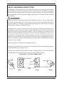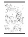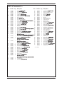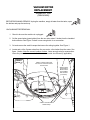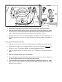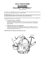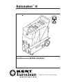
1
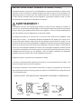
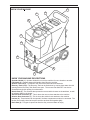
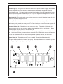
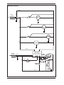
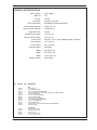
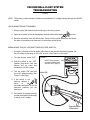
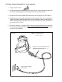
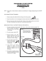
Rainmaker™ H
Instructions for use and parts list
Kent/Euroclean MODEL 56649981
06/03 revised 11/03 Form Number 56041563
INTRODUCTION
This manual will help you get the most from your Kent/Euroclean RainmakerTM H. Read thoroughly
before operating the machine.
NOTE: Bold numbers in parenthesis indicate an item illustrated on page 7.
This product is intended for commercial use only.
PARTS AND SERVICE
Repairs, when required, should be performed by your authorized Kent/Euroclean Service Center, who
employs factory-trained service personnel, and maintains an inventory of Kent/Euroclean original
replacement parts and accessories.
Call the Kent/Euroclean DEALER named below for parts or service. Please specify the Model and
Serial Number when discussing your machine.
(Dealer, affix service sticker here)
NAME PLATE
The Model and Serial Number of your machine are shown on the nameplate in the machine. This
information is needed when ordering repair parts for the machine. Use the space below to note the
Model and Serial Number of your machine for future reference.
MODEL : ________________________________________
SERIAL NUMBER : _____________________________________
UNCRATING
When the machine is delivered, carefully inspect the shipping carton and the machine for damage. If
damage is evident, save the shipping carton so that it can be inspected. Contact Kent/Euroclean
Customer Service Department immediately to file a freight damage claim.
DO NOT OPERATE THE MACHINE UNTIL YOU HAVE READ THIS SECTION.
IMPROPER USE WILL VOID THE WARRANTY.
• Always use a defoamer when foaming occurs to prevent vacuum motor damage.
• Never use water above 140° F (60°C).
• Do not store outdoors. Avoid extremes in temperature.
• Do not let the pump run dry. Turn the pump off and refill that tank when cleaning solution
•
gets low.
Use approved chemicals only. All chemicals should be mixed thoroughly. Liquid chemicals
are recommended to prevent powder buildups. A pH between 6 and 9 is recommended.
The use of high alkaline detergents or strong acids will accelerate the wear of the pump
and seals, and will void the warranty.
• All extension cords must have a rating of at least 12/3 (#12 cord). Extension cords should
be no longer than 50 feet. Replace the plug immediately if the ground prong becomes
damaged or is broken off.
2 - FORM NO. 56041563 / Rainmaker™ H
IMPORTANT SAFETY INSTRUCTIONS
This machine is only suitable for commercial use, for example in hotels, schools, hospitals,
factories, shops and offices other than normal residential housekeeping purposes.
When using an electrical appliance, basic precautions should always be followed, including
the following:
Read all instructions before using this appliance.
WARNING!
To reduce the risk of fire, electric shock, or injury:
•
•
•
•
•
•
•
•
•
•
•
•
•
•
•
•
Do not leave the appliance when it is plugged in. Unplug the unit from the outlet when not in
use and before servicing.
To avoid electric shock, do not expose to rain. Store indoors.
Do not allow to be used as a toy. Close attention is necessary when used near children.
Use only as described in this manual. Use only the manufacturer’s recommended attachments.
Do not use with damaged cord or plug. If the appliance is not working as it should be, has
been dropped, damaged, left outdoors or dropped into water, return it to a service center.
Do not pull or carry by the cord, use the cord as a handle, close a door on the cord, or pull the
cord around sharp edges or corners. Do not run the appliance over the cord. Keep the cord
away from heated surfaces.
Do not unplug by pulling on the cord. To unplug, grasp the plug, not the cord.
Do not handle the plug, cord or appliance with wet hands.
Do not put any object into openings. Do not use with any opening blocked; keep free of dust,
lint, hair, and anything that may reduce air flow.
Keep loose clothing, hair, fingers, and all parts of body away from openings and moving parts.
Do not pick up anything that is burning or smoking, such as cigarettes, matches, or hot ashes,
or any health endangering dusts.
Turn off all controls before unplugging.
Use extra care when cleaning on stairs.
Do not use to pick up flammable or combustible liquids such as gasoline or use in areas
where they may be present.
Connect to a properly grounded outlet only. See Grounding Instructions.
Liquid ejected at the spray nozzle could be dangerous as a result of its temperature, pressure
or chemical content.
SAVE THESE INSTRUCTIONS
FORM NO.56041563 / Rainmaker™ H - 3
CONSIGNES DE SECURITE IMPORTANTES
Cette machine ne convient qu´à un usage industriel, par exemple dans des hôtels, écoles,
hôpitaux, usines, boutiques et bureaux et autres à l´exclusion de tout usage de maintenance
résidentielle normale.
L’utilisation d’un appareil électrique demande certaines précautions:
LIRE TOUTES LES INSTRUCTIONS AVANT DE FAIRE FONCTIONNER (CET APPAREIL)
AVERTISSEMENT!
Pour réduire les risques d’incendie, de choc électrique ou de blessure:
•
•
•
•
•
•
•
•
•
•
•
•
•
•
•
•
Ne pas laisser l’appareil sans surveillance lorsqu’il est branché. Débrancher lorsque l’appareil
n’est pas utilisé et avant l’entretien.
Pour réduire les risques de choc électrique, utiliser à l’intérieur seulement.
Ne pas permettre aux enfants de jouer avec l’appareil. Une attention particulière est
nécessaire lorsque l’appareil est utilisé par des enfants ou à proximité de ces derniers.
N’utiliser que conformément à cette notice avec les accessoires recommandés par le fabricant.
Ne pas utiliser si le cordon ou la fiche est endommagé. Retourner l’appareil à un atelier de
réparation s’il ne fonctionne pas bien, s’il est tombé ou s’il a été endommagé, oublié à l’extérieur
ou immergé.
Ne pas tirer soulever ou traîner l’appareil par le cordon. Ne pas utiliser le cordon comme une
poignée, le coincer dans l’embrasure d’une porte ou l’appuyer contre des arêtes vives ou des
coins. Ne pas faire rouler l’appareil sur le cordon. Garder le cordon à l’écart des surfaces
chaudes.
Ne pas débrancher en tirant sur le cordon. Tirer plutôt la fiche.
Ne pas toucher la fiche ou l’appareil lorsque vos mains sont humides.
N’insérer aucun objet dans les ouvertures. Ne pas utiliser l’appareil lorsqu’une ouverture est
bloquée. S’assurer que de la poussière, de la peluche, des cheveux ou d’autres matières ne
réduisent pas le débit d’air.
Maintenir les cheveux, les vêtements amples, les doigts et toutes les parties du corps à l’écart des
ouvertures et des pièces mobiles.
Ne pas aspirer de matières en combustion ou qui dégagent de la fumée, comme des cigarettes,
des allumettes ou des cendres chaudes.
Mettre toutes les commandes à la position ARRÊT avant de débrancher l’appareil.
User de prudence lors du nettoyage des escaliers.
Ne pas aspirer des liquides inflammables or combustibles, comme de l’essence, et ne pas faire
fonctionner dans des endroits ou peuvent se trouver de tels liquides.
Ne brancher qu’à une prise de courant avec mise à la terre. Voir les instructions visant la mise à
la terre.
Le liquide qui sort de l’embout de vaporisation peut s’avérer dangereux en raison de sa
température, de sa pression ou du produit chimique qu’il contient.
CONSERVER CES INSTRUCTIONS
4 - FORM NO. 56041563 / Rainmaker™ H
120VAC GROUNDING INSTRUCTIONS
This appliance must be grounded. If it should electrically malfunction, grounding provides a path of
least resistance for electric current to reduce the risk of electric shock. This appliance is equipped
with a cord having an equipment-grounding conductor and grounding plug. The plug must be plugged
into an appropriate outlet that is properly installed and grounded in accordance with all local codes
and ordinances.
DANGER!
Improper connection of the equipment-grounding conductor can result in a risk of electric shock.
Check with a qualified electrician or service person if you are in doubt as to whether the outlet is
properly grounded. Do not modify the plug provided with the appliance. If it will not fit the outlet, have
a proper outlet installed by a qualified electrician.
This appliance is for use on a nominal 120-volt circuit, and has a grounding plug that looks like the
plug illustrated in Figure 1 below. A temporary adapter illustrated in Figures 2 and 3 may be used to
connect this plug to a 2-pole receptacle as shown in Figure 2 if a properly grounded outlet is not
available. The temporary adapter should be used only until a properly grounded outlet (Figure 1) can
be installed by a qualified electrician. The green-colored rigid ear, tab, or the like extending from the
adapter must be connected to a permanent ground such as a properly grounded outlet box cover.
Whenever the adapter is used, it must be held in place by a metal screw. Grounding adapters are not
approved for use in Canada.
Replace the plug if the grounding pin is damaged or broken.
The Green (or Green/Yellow) wire in the cord is the grounding wire. When replacing a plug, this wire
must be attached to the grounding pin only.
Extension cords connected to this machine should be 12 gauge, three-wire cords with three-prong
plugs and outlets. DO NOT use extension cords more than 50 feet (15 m) long.
PLEASE NOTE: FOR NORTH AMERICA ONLY
FORM NO.56041563 / Rainmaker™ H - 5
INSTRUCTIONS VISANT LA MISE À LA TERRE (120VAC)
Cet appareil doit être mis à la terre. En cas de défaillance ou de panne éventuelles, la mise a la terre
fournit au courant un chemin de moindre résistance qui réduit le risque de choc électrique. Cet
appareil est pourvu d’un cordon muni d’un conducteur de terre et d’une fiche avec broche de terre.
La fiche doit être branchée dans une prise appropriee correctement installée et mise à la terre
conformément aux règlements et ordonnances municipaux.
AVERTISSEMENT !
Un conducteur de terre mal raccordé peut entraîner un risque de choc électrique. Consulter un
électricien ou un technicien d’entretien qualifié si vous n’êtes pas certain que la prise est correctement
mise à la terre. Ne pas modifier la fiche fournie avec l’appareil - si elle ne peut être insérée dans la
prise, faire installer une prise adéquate par un électricien qualifié.
Cet appareil est destiné à un circuit de 120 V et est muni d’une fiche de terre semblable à celle
illustrée par le croquis 1. Un adaptateur temporaire semblable à celui illustré par le croquis 2 et C
peut être utilisé pour brancher cette fiche à une prise bipolaire comme l’illustre le croquis 2 si une
prise avec mise à la terre n’est pas disponible. L’adaptateur temporaire devrait etre utilisé seulement
jusqu’à ce qu’une prise avec mise à la terre soit installée par un électricien qualifié. L’oreille rigide ou
le crochet ou autre dispositif semblable, de couleur verte, prolongeant l’adaptateur doit Iêtre raccordé
à un élément correctement mis à la terre comme le couvercle d’une boîte de sortie mise à la terre.
L’adaptateur doit être fixé par une vis métallique. Note: Au Canada, I’utilisation d’un adaptateur
temporaire n’est pas autorisée par le Code canadien de l’électricité.
Remplacez la prise si la prise de terre est abîmée ou cassée.
Le fil Vert (ou Vert/Jaune) dans la ganse est le fil de terre. Lors du remplacement d´une prise, ce fil
doit être raccordé à la prise de terre uniquement.
Les ralonges connectées à cette machine doivent avoir 12 mesures, trois ganses de fil ayant trois
fiches masculines féminines tree-prong plugs and outlets. N´UTILISEZ PAS de ralonge de plus de
15 m (50 pieds) de long.
VEUILLEZ NOTER: CES INSTRUCTIONS CONCERNENT UNIQUEMENT L’AMÉRIQUE DU
NORD
6 - FORM NO. 56041563 / Rainmaker™ H
KNOW YOUR MACHINE
1
5
3
4
6
9
2
8
7
KNOW YOUR MACHINE DESCRIPTIONS
Operator Handle (1) - Operator holds this to move the machine from one location to another.
Lift Handle (2) - Operator grasps this handle when lifting the machine.
Solution Tank Lid (3) - Fill Solution Tank here with warm water and chemicals.
Recovery Tank Lid (4) - The Recovery Tank can be flushed out by running clean water into this
opening with the Recovery Tank Drain Hose open. The vacuum float Shut-OFF can also be
accessed through this opening for maintenance.
Switch Plate (5) - The switches that operate the motors and the heater are located here, as well
as indicator lights for the heater.
Vacuum Hose Connector (6) - This is where the vacuum hose attaches to the machine.
Solution Hose Connector (7) - This is where the solution hose attaches to the machine.
Latches (8) - These latches can be opened if the base compartment needs to be accessed. The
latches are normally closed to keep the machine sections held together tightly.
Drain Gate (9) - This gate is opened to allow the dirty recovered water to empty.
FORM NO.56041563 / Rainmaker™ H - 7
SWITCH PLATE DESCRIPTIONS
Locator Light (1) - This green light will turn on when the two power cords are plugged into separate
circuits. Separate circuits are defined as outlets fed by circuit breakers on opposite sides of the
circuit breaker panel. This feature helps to prevent blown breakers. When the locator light (1) turns
on, the heat exchanger will automatically turn on. If you can not get the locator light to turn on, use
the Heat Switch (2) to turn the heat exchanger on.
Heat Switch (2) - This rocker switch turns the heat exchanger on and off, when the Locator light (1)
is not on. The switch will light when ON.
Mode Light (3) - This indicator light will turn on while the heat exchanger is actively heating. It will
turn off when the heater has reached operating temperature. Normally, this light will be on most of
the time as you do your job, but it may go out if you stop cleaning to move furniture or to empty or fill
the tanks.
Vacuum 1 Switch (4) - This switch turns one vacuum on and off. The switch will light when ON.
When operating with only one vacuum -- as when cleaning delicate fabric -- use Vacuum 1. When
cleaning carpet, use both Vacuum 1 and Vacuum 2 (5).
Vacuum 2 Switch (5) - This switch turns the second vacuum on and off. The switch will light when
ON. Use this switch when you want maximum vacuum lift. The CFM of both motors is the same as
it is for one motor alone, since the vacuums are operated in parallel; however, the vacuum lift
doubles when both vacuums are running.
Pump Switch (6) - This switch turns the pump on and off. The switch will light when ON.
The pump in this machine is a “demand” style pump. This means the pump only runs when you are
actually spraying. Once spraying stops, the pump stops running.
➀
➄
➃
➁
➅
O
O
O
O
I
I
I
I
212° F
➂
8 - FORM NO. 56041563 / Rainmaker™ H
MACHINE WIRING
Line
VAC 1
SW
Green
115V
Black
White
∼
Power
Cord #1
Neutral
White
VAC 2
SW
PUMP
Black
White
SW
FAN
Black
P3
P2 P5
P6
Black
White
P7
White
“LOCATOR”
LIGHT
“MODE”
LIGHT
Thermostat
HEAT
EXCHANGER
•
Thermal
Fuse Black
White
Black
∼
P1
•
115V
Black
Green
∼
Power
Cord #2
P4
Dual Cord
Sensor Board
Black
FORM NO.56041563 / Rainmaker™ H - 9
OPERATION
1
2
Inspect the machine, hoses, and cleaning tools for cleanliness and completeness.
Fill the solution tank with warm water. Using warm water may be a benefit in cleaning
effectiveness, but do not use hot water (above 140°F / 60°C) in the tank. Add liquid cleaning
solution with a pH of between 6 and 9.
3 Plug in the power cords. Do not connect both cords to the same outlet; the circuit locator
light on the switch plate should light up. If the locator light does not come on, try different
outlets until it does. If you are certain the cords are on separate circuits, turn the heat
switch on. CAUTION: using the heat switch when the cords are on the same circuit may
cause the breaker to trip. NOTE: the cord with the red sleeve powers the heat exchanger.
4 Attach the spray hose to the solution quick disconnect and the vacuum hose to the hose
barb on the recovery tank. Attach the other ends of the hoses to the cleaning tool.
5 Turn the pump on and spray from the tool to make sure everything is working, and to fill the
heat exchanger with water. NOTE: the pump has a built in pressure switch; the pump only
runs when you are spraying.
6 Allow the heat exchanger two minutes to reach operating temperature.
7 Turn the pump on. Turn the vacuums on.
8 Begin cleaning using the correct hoses and tool.
9 Use defoamer in the recovery tank any time foaming occurs.
10 Monitor water level in the solution tank. Do not let the pump run dry.
11 When the solution tank gets low, turn off the pump, fill the solution tank, empty and clean the
recovery tank.
12 When finished with the job, remove any unused solution from the solution tank, and run a
few gallons of clean water through the system.
BALL FLOAT VACUUM SHUT-OFF
Prior to using the machine, always check that the float filter is clean and the ball can travel freely.
When the recovery tank is full, the ball float will rise and will shut off the vacuum flow to prevent
any more water from entering the tank. Turn off the vacuum, and empty the recovery tank.
NOTE: if foam is present, or if the ball float is prevented from rising, the float will not be able to
stop the air flow, and the tank may over fill.
CAUTION!
To avoid vacuum motor damage, always make sure the float filter is clean and the ball can travel
freely prior to using the machine. And always use a defoamer when foaming occurs.
ELECTRIC CIRCUIT LOCATOR
This unique, patented system is operated by a solid state circuit. It will inform the operator when
the two cords are plugged into separate circuits by turning the circuit locator light (1) on. This
helps to prevent tripping circuit breakers.
NOTE: if the circuit locator light does not illuminate when the cords are plugged in, then both
cords are on the same circuit. Try other outlets with one of the cords until you get the locator light
to come on.
CAUTION: if the Heat switch (2) is turned on when both cords are on the same circuit, the
breaker will trip.
10 - FORM NO. 56041563 / Rainmaker™ H
USE AND MAINTENANCE
1
2
3
4
5
6
7
8
Use only liquid chemicals with a pH between 6 and 9 at the recommended mix ratios. Improper
chemicals, or improperly mixed chemicals, can cause possible damage to the pump, seals, and
other components.
Turn the pump “off” when the solution tank is low on fluid. Do not let the pump run dry.
Regularly clean any mineral or chemical deposits in the heat exchanger, lines and pump with a
mild acid descaler. Rinse the descaler out of the machine with a few gallons of clear water.
Prior to each job, inspect, and clean if needed, the solution filter, the recovery tank float filter,
and the drain hose.
Make sure the airways are not blocked before each use.
Inspect the carbon brushes on the vacuum motors once a year. Replace if worn down.
Clean the Recovery Tank daily. Clean the body and wheels as needed.
Keep the machine from extremes in temperatures.
MAINTENANCE SCHEDULE
Daily
FLUSH LINES & PUMP
X
CLEAN VACUUM FLOAT FILTER
X
CLEAN SOLUTION FILTER
X
CHECK INLET AIRWAYS
X
DESCALE MACHINE
CHECK VACUUM MOTOR BRUSHES
Monthly
Yearly
X
X
FORM NO.56041563 / Rainmaker™ H - 11
12 - FORM NO. 56041563 / Rainmaker™ H
PART LIST RAINMAKERTM H
Item
Ref. No. Qty
1
1A
2
3
4
4A
4B
5
6
7
8
8A
8B
8C
9
9A
10
13
14
15
16
17
18
19
20
20A
56649987
56649987
56102816
56108074
56649987
56649987
56649987
56649983
56108061
56102816
56108055
56108054
56102816
56102812
56102816
56102816
56108052
56108053
56102817
56102841
56102825
56102817
56102869
56102825
56102825
56102813
1
1
8
2
1
1
1
1
1
1
1
2
1
1
6
6
1
1
4
1
1
1
1
1
4
3
21
22
23
56102825
56102825
56102825
1
1
1
24
56102825
1
24A
25
26
27
28
29
30
30A
31
32
33
38
39
40
56102825
56102816
56102816
56102818
56102818
56102842
56102816
56102815
56102816
56102816
56102829
56102843
56102816
56102813
1
18
18
2
2
2
6
1
6
6
1
1
4
1
41
42
45
56102844
56102845
56649989
1
2
2
Description
Item
Drain Gate (Drain Gate Kit)
Spout (Drain Gate Kit)
Screw, 8-32 x .50 (Hardware Kit)
Latch, Rubber W/Strike
O-Ring, Small (Drain Gate Kit)
O-Ring, Large (Drain Gate Kit)
Nut, Cast Aluminum, 1-1/2” (Drain Gate Kit)
Recovery Tank, Blue
Hose Barb
Gasket (Hardware Kit)
Lid, 6”, Clear Center, W/Ring
Chain, 8” (also included in Solution Lid kit 56102812)
Screw, 10-32 x .62 (Hardware Kit)
Screw, 10-32 x .38 (Solution Lid Kit)
Screw, 8-32 x .88 (Hardware Kit)
Lock Nut, 8-32 (Hardware Kit)
Float, Ball and Cage on Manifold
PVC Elbow
Hose Clamp (Hose Clamp Kit)
Hose, Vacuum, 2” x 41”, Ribbed
Heat Exchanger, Complete (Heat Exchanger
Exchanger,, Complete)
Hose Clamp (Hose Clamp Kit)
Mount Bracket, Heat Exchanger
Hose, Braided SS (Heat Exchanger
Exchanger,, Complete)
Washer, Brass (Heat Exchanger
Exchanger,, Complete)
Washer, Fiber
(Quick Disconnect Kit)
(also included in Heat Exchanger
Exchanger,, Complete 56102825)
Nipple, Stainless Steel (Heat Exchanger
Exchanger,, Complete)
Bushing, Fiber (Heat Exchanger
Exchanger,, Complete)
Heat Control Switch
(Heat Exchanger
Exchanger,, Complete)
(also part of Heat Repair Kit 56102819)
Elbow, Brass
(Heat Exchanger
Exchanger,, Complete)
(also part of Hose Barb Kit 56102829)
Coupling, Brass (Heat Exchanger
Exchanger,, Complete)
Washer, Flt 3/16 (Hardware Kit)
Lock Nut, 1/4 (Hardware Kit)
acuum Motor Kit)
Vacuum Motor, 120V (V
(Vacuum
acuum Motor Kit)
Gasket, Vacuum Motor (V
(Vacuum
Manifold
Bolt, 1/4-20 x 5.00 (Hardware Kit)
Bracket, Vacuum Motor (Bracket Kit)
Washer, Split Lock (Hardware Kit)
Nut, Finish (Hardware Kit)
Hose Barb, Straight (Hose Barb Kit)
Handle, Chrome
Bolt, 1/4-20 x .75 (Hardware Kit)
Quick Disconnect, 1/4 NPT
(Quick Disconnect Kit)
(also included in Heat Exchanger
Exchanger,, Complete 56102825)
Flange, Exhaust
Louver, W/Screws
PVC Reducer (Cord Retainer Kit)
46
47
48
49
50
51
52
53
54
55
57
58
59
60
61
62
63
68
69
70
71
73
74
77
78
79
80
82
83
84
85
86
87
88
89
90
91
92
*
Ref. No. Qty
56649989
56102866
56102867
56102847
56102811
56102811
56649988
56102850
56649986
56102810
56649984
56102853
56102854
56102812
56102817
56649985
56102829
56102839
56102858
56102816
56102863
56102827
56102828
56102816
56102816
56108096
56108096
56102860
56102856
56102816
56102816
56102848
56102816
56102816
56102816
56102815
56102815
56102816
56108093
2
1
1
1
2
2
2
2
2
1
1
1
1
1
4
1
2
1
1
5
2
3
1
4
4
1
1
1
2
4
4
2
3
3
8
1
1
4
1
Description
Cord Retainer (Cord Retainer Kit)
Dual Cord Sensor PCB
Snap Track, PCB Mount x 4” LG
Axle Rod, Plated, 18.25”
Wheel, 10” (Wheel Kit)
Axle Cap (Wheel Kit)
Cord, 12/3, 25ft
Hinge Pin
Label, Kent / Euroclean
Base Compartment, Gray
Solution Tank, Blue
Filter, Pump Inlet
Nipple, PVC 1/2 NPT
Lid, Solution Tank (Solution Lid Kit)
Hose Clamp (Hose Clamp Kit)
Pump, 100PSI, 120V
Hose Barb, Elbow (Hose Barb Kit)
Hose, 3/8”ID x 76”LG
Switch Plate
Screw, #4 x 3/8” (Hardware Kit)
Light, Green, 120V
Switch, SPST, W/Cover
Switch, DPDT, W/Cover
Screw, 6-32 x 2.00 (Hardware Kit)
Lock Nut, 6-32 (Hardware Kit)
Fan, 120V (Fan Kit)
Fan Guard (Fan Kit)
Gasket, 7ft
Cord Wrap, Black
Bolt, 1/4-20 x 1.00 (Hardware Kit)
Washer, Flt SS 1/4 (Hardware Kit)
Castor, 4”, No Brake
Screw, 10-32 x .62 (Hardware Kit)
Lock Nut 10-32 (Hardware Kit)
Bolt, 1/4-20 x .75 (Hardware Kit)
Bracket, Mating (Bracket Kit)
Bracket, Mating W/Hole (Bracket Kit)
Bolt, 1/4-20 x 1.25 (Hardware Kit)
Label, Warning
* = Not Shown
revised 11/03
FORM NO.56041563 / Rainmaker™ H - 13
TECHNICAL SPECIFICATIONS
Vacuum Motor:
Water lift:
150”
Air Flow:
100 cfm
Amp Draw:
Tank Construction:
16 amps, each cord
Rotationally molded polyethylene
Solution Tank Capacity:
14 Gal. (53.2 L)
Recovery Tank Capacity:
12 Gal.(45.4 L)
Application Flow:
100 psi
Solution Hose Length:
15 ft. (4.5 m)
Recovery Hose Length:
15 ft. (4.5 m)
Power Cord:
10 in. (25 cm)
Front Castors:
4 in. (10.2 cm)
2000 Watt
Height:
38 in (96.5 cm)
Length:
36 in (91.4 cm)
Width:
Machine weight:
Ref. No. Qty
Two 25 ft. (7.6 m), High visability yellow, removable
Rear Wheels:
Heat Exchanger:
Item
Two 2-Stage
17.6 in (44.7 cm)
83 lb (38 kg)
Description
56108096
56102811
56102812
56102816
56102817
56102818
56649987
56649989
56102829
56102813
56102815
56102825
56102819
1
1
1
1
1
1
1
1
1
1
1
1
1
KITS
Fan Kit (#79, 80)
Wheel Kit (1 each of #50, 51)
Solution Lid Kit (#8C, 60 / also includes #8A)
Hardware Kit (#2, 7, 8B, 9, 9A, 25, 26, 30, 31, 32, 39, 44, 70, 77, 78, 84, 85, 87-89, 92)
Hose Clamp Kit (#14, 17, 61)
Vacuum Motor Kit (1 each of #27, 28)
Drain Gate Kit (#1, 1A, 4-4B)
Cord Retainer Kit (1 each of #45, 46)
Hose Barb Kit (#33, 63 / also includes #24)
Quick Disconnect Kit (#20A, 40)
Bracket Kit (#30A, 90, 91)
Heat Exchanger, Complete (#16, 19, 20, 21-24A / also includes #20A, 40)
Heat Repair Kit (#23)
56102804
56102805
56102807
56102861
56102871
1
1
1
1
1
ACCESSORIES
Single Bend Wand Assembly
Double Bend Wand Assembly
Extractor Hand Tool
Vac Hose / Pressure Line 25ft.
Vac Hose / Pressure Line 15ft.
14 - FORM NO. 56041563 / Rainmaker™ H
NOTES
FORM NO.56041563 / Rainmaker™ H - 15
VACUUM BALL-FLOAT SYSTEM
TROUBLESHOOTING
(120V)
NOTE: The motors on these extractor models are controlled by AC voltage passing through the ON/OFF
switch.
VACUUM MOTOR NOT RUNNING:
1. Always unplug the machine before working on the wiring system.
2. Open the machine to look for damaged or disconnected wires leading to the vac motor.
3. Remove the screws from the switch plate. Gently turn the switch plate over and check
the back of the switches to make sure no wires have pulled loose.
MEASURING THE AC VOLTAGE THROUGH THE SWITCH:
1. Connect a voltmeter to the terminals (with wires) on the vacuum switch being tested. Set
the AC voltage in the range of 120 volts, or more. (See Figure 1 to the right).
2. Turn the vacuum switch “OFF”.
FIGURE 1
NOTE: There should be
no voltage reading when
switch is “OFF” (Step 3).
3. With the switch in the “OFF”
position, plug the #1 Cord (red
sleeve) into an outlet and
measure for NO AC voltage.
.
4. Turn the switch “ON” and look
for an AC voltage reading. (See
Figure 1 to the right).
Switch ON
5. If the switch is not
working, replace it.
Refer
to
the
schematic and parts list for the
particular machine you are
working on.
6. If the switch is working correctly,
test the motor itself by connecting
it directly to AC voltage.
Opposite sides
of the switch
TESTING THE MOTOR DIRECTLY TO AC VOLTAGE:
1. Unplug the power cords.
2. Cut both the power wires leading from the vacuum motor, several inches from the motor
itself. Leave enough length for reconnecting the wires. See Figure 2 below.
3. Connect the motor wires (leading from the motor) to an AC jumper wire. See Figure 2.
4. Plug the jumper into an outlet. Does the vacuum motor run? If the vacuum motor runs,
unplug the jumper, visually inspect and/or use the “continuity tester” or “ohm meter” to
find the opening between the switch and motor wires. Refer to the wiring schematic for
your machine model. Repair.
5. If the motor does not run, replace it. Refer to the parts list and schematic for your machine
for the correct part number. Refer to Vacuum Motor Replacement Instructions for steps
on removal and installation.
FIGURE 2
NOTE:
Do
not remove
theremove the moNOTE:
Do not
motor to test
tor it.
to test.
Step 2 & 3: Cut both power wires several inches from the motor and connect to an AC jumper wire.
Step 5: Plug the jumper
into an outlet.
VACUUM BALL-FLOAT SYSTEM
TROUBLESHOOTING
AquaProTM 300
(120V)
NOTE: The motors on these extractor models are controlled by AC voltage passing through the ON/OFF
switch.
VACUUM MOTOR NOT RUNNING:
1. Always unplug the machine before working on the wiring system.
2. Open the machine to look for damaged or disconnected wires leading to the vac motor.
3. Remove the screws from the switch plate. Gently turn the switch plate over and check
the back of the switches to make sure no wires have pulled loose.
MEASURING THE AC VOLTAGE THROUGH THE SWITCH:
1. Connect a voltmeter to the terminals (with wires) on the vacuum switch being tested. Set
the AC voltage in the range of
FIGURE 1
120 volts, or more. (See Figure
1 to the right).
NOTE: There should be
no voltage reading when
switch is “OFF” (Step 3).
2. Turn the vacuum switch “OFF”.
3. With the switch in the “OFF”
position, plug the #1 Cord (red
sleeve) into an outlet and
measure for NO AC voltage.
.
Switch ON
4. Turn the switch “ON” and
look for an AC voltage
reading. (See Figure
1 to the right).
5. If the switch is not working,
replace it. Refer to the
schematic and parts list for the
particular machine you are
working on.
6. If the switch is working correctly,
test the motor itself by connecting
it directly to AC voltage.
Opposite sides
of the switch
TESTING THE MOTOR DIRECTLY TO AC VOLTAGE:
1. Unplug the power cords.
2. Cut both the power wires leading from the vacuum motor, several inches from the motor
itself. Leave enough length for reconnecting the wires. See Figure 2 below.
3. Connect the motor wires (leading from the motor) to an AC jumper wire. See Figure 2.
4. Plug the jumper into an outlet. Does the vacuum motor run? If the vacuum motor runs,
unplug the jumper, visually inspect and/or use the “continuity tester” or “ohm meter” to
find the opening between the switch and motor wires. Refer to the wiring schematic for
your machine model. Repair.
5. If the motor does not run, replace it. Refer to the parts list and schematic for your machine
for the correct part number. Refer to Vacuum Motor Replacement Instructions for steps
on removal and installation.
FIGURE 2
NOTE:
Do
not remove
theremove the moNOTE:
Do not
motor to test
tor it.
to test.
Step 2 & 3: Cut both power wires several inches from the motor and connect to an AC jumper wire.
Step 5: Plug the jumper
into an outlet.
VACUUM MOTOR
REPLACEMENT
AquaProTM 300
(120V & 240V)
BEFORE BEGINNING REPAIRS: Unplug the machine, empty all water from the tanks, open
the latches and prop the tanks up.
VACUUM MOTOR REMOVAL:
1. Check to be sure the machine is unplugged.
2. Cut the ground wires (green/yellow) from the vac motor, about 3 inches from the insulated
butt connector. See Figure 1 below. Leave enough wire for re-connection.
3. Cut and remove the small tie wraps that secure the wiring together. See Figure 1.
4. Locate and cut the 2 power wires from the vac motor, a few inches from the motor. See
figure 1 below. Note the correct location of wires. Leave enough wire for reconnection.
Leave the power wires connected to the vacuum control circuit board (if applicable).
FIGURE 1
STEP 4: Cut the 2 power cords
from the vac motor a few inches
from the motor.
STEP 2: Cut the
ground wire(s)
about 3 inches
from insulated
butt connector
(not shown).
STEP 3: Cut and remove
small tie wraps
FIGURE 1
Solution
Lines
Exhaust
Hose
FIGURE 2
FIGURE 3
Exhaust
Hose
STEP 5: Remove 3 nuts
holding motor to mounting bolts. (3rd nut not
shown).
Heat
Exchanger
Vacuum
Motor
STEP 6: Loosen hose
bracket and slide
exhaust hose down.
5. Remove the 3 nuts which hold the motor to the mounting bolts. See Figure 2 above.
6. Slide the exhaust vacuum hose (under the machine) down to free the exhaust port on the
vacuum motor. You will have to loosen the hose bracket, located underneath the machine, in
order to move the bracket aside to free the exhaust hose. See Figure 3 above.
7. Gently pull the vacuum off the mounting bolts. Avoid pulling on the solution line(s) or
electrical wires when removing the motor. Replace the vacuum gasket if damaged or
worn.
VACUUM MOTOR INSTALLATION:
1. Align the vacuum motor over the 3 mounting bolts and gently slide it towards the gasket.
2. Tighten the mounting nuts in a rotational pattern, until the vacuum gasket just begins to
compress evenly. Do not over-tighten, as motor damage may occur.
3. Slide the exhaust hose up onto the port on the motor. Tighten the hose bracket under the
base.
4. Strip the insulation from the wires, as necessary.
5. Connect the green ground wire by crimping it into the provided butt connector. Make sure
you have a tight connection. Do not leave bare wires exposed.
6. Connect the three motor wires to the matching power wires that were previously cut. Make
sure you have a tight connection. Do not leave bare wires exposed. Refer to the wiring
diagram for your machine.
LOW VACUUM LIFT
PRE-TROUBLESHOOTING
ALL MACHINES
(120V & 240V)
Before beginning to troubleshoot the vacuum system on your machine, check all the possible causes of low
vacuum lift listed below.
ALL EXTRACTORS:
1. The vacuum inlet filter in the recovery tank is dirty.
2. Debris is plugging the cleaning tool and/or vac hose.
3. The lid is cracked or ring gasket is damaged.
4. The drain gate, or drain hose plug, is not closed all the way.
5. The vacuum hose from the recovery tank to the vac motor is damaged.
7. The recovery tank is warped or cracked.
8. Debris is impeding air movement on the impellers in the motor (usually caused by dry
vacuuming without the proper filter).
100 & 150 PSI PUMP
ADJUSTMENT
RainmakerTM and AquaProTM
(120V & 240V)
This pump has an adjustable pressure switch. If the pump pulsates during operation, see step “A” below. If
the pump does not shut off after spraying, see step “B” below.
IMPORTANT NOTICE: Older pumps may pulsate when not spraying. This is due to normal wear of
the Internal Bleed Back Valve and is not cause for repair unless excessive.
To adjust the pressure switch, use a 5/64" Allen wrench at the pump head, as shown in the diagram below,
and follow either step “A” or “B” as necessary.
A. PULSATING DURING OPERATION:
First make sure there are no clogs in either the hose or spray tip. This will cause pulsating
during spraying. If no clogs are found, turn the Allen wrench clockwise, 1/4 turn at a
time, and retest.
B. PUMP DOES NOT SHUT OFF COMPLETELY:
First make sure there are no leaks in the hoses, valve or pump. If no leaks are found, turn
the Allen wrench counterclockwise, 1/4 turn at a time, and retest. The pump may need
replacing if adjustment does not work.
CAUTION: Excessive adjustment may damage the pump.
CLOCKWISE