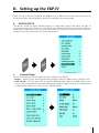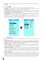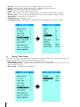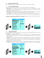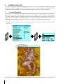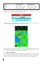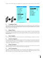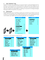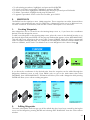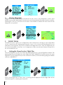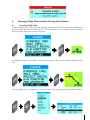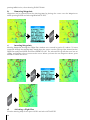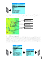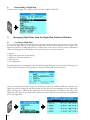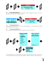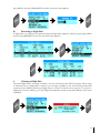
1
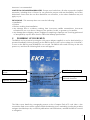
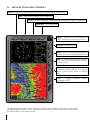
EKP-IV Pro
Quick Start Guide
Updated to V2.01.86R
Via Caboto, 9
54036 Marina di Carrara - MS - ITALIA
E-mail: [email protected]
Table of contents
I.
Introduction to the EKP-IV
A.EKP-IV Parts List
B.
IMPORTANT: Warnings and Warranty
C. Powering up your EKP-IV
D.EKP-IV Buttons and Controls
II.Setting up the EKP-IV
A.System Setup
1.
General Setup
2.
Fix Setup
3.
Alarm Setup
4.
Track Setup
5.
Units Setup
6.
Date & Time Setup
B.
Moving Map Setup
1.
Auto Position Mode
2.
Map Orientation
3.
Range Rings
4.
The Data Window
5.
VFR Settings
6.
Airspace Settings
7.
Land Settings
8.
Other Settings
C.Selective Display
D. Points of Interest (POI) Settings
E.
Terrain and TAWS
1.
Terrain Depiction
2.
TAWS (Terrain Awareness Warning System)
F.
The Calculator
1.
Countdown Timer
2.
Elapsed Timer
3.
Trip Computer
4.
Vertical Navigation
5.
Wind Calculation
6.
Fuel Consumption
III.Flying with the EKP-IV
A. The GOTO Button
B.
The PAGE Button
C. The CLEAR Button
D.Checklists
E.
Waypoints
1.
Creating Waypoints
2.
Editing Waypoints
3.
Moving Waypoints
F.Flight Plans
1.
Setting the Viewed (active) Flight Plan
2.
Managing Flight Plans from the Moving Map Window
a)
Creating a Flight Plan
b)
Removing Waypoints
c)
Inserting Waypoints
4
4
5
6
7
7
8
8
9
9
10
11
11
11
12
12
14
15
15
16
16
17
18
18
19
20
21
21
21
21
21
21
22
22
24
24
25
25
25
26
26
26
27
27
28
28
d)
e)
f)
Activating a Flight Plan
Selecting an Approach
Deactivating a Flight Plan
3.
Managing Flight Plans from the Flight Plan Database Window
a)
Creating a Flight Plan
b)
Removing Waypoints
c)
Inserting Waypoints
d)
Activating a Flight Plan
e)
Selecting an Approach
f)
Deactivating a Flight Plan
g)
Renaming a Flight Plan
h)
Reversing a Flight Plan
i)
Clearing a Flight Plan
IV.Advanced Functions of the EKP-IV
A.File Manager
B.Serial Port Data Transfer
1.
Download or Upload Waypoints
2.
Download or Upload Flight Plan
3.
Download Track
28
29
30
30
30
31
31
31
32
32
32
33
33
34
35
35
35
36
V. PRO FUNCTIONS
A.Functions for the automatic creation of Search and Rescue
(S.A.R) flight pattern
B.Customized Regional Coverage Area
C. Place and Street Research
1.
Place Research
2.
Street Research
D.Connection to the radio localiz. system Telefix and/or
Kenwood APRS, Automatic Position Reporting System
VI. Troubleshooting the EKP-IV
A.
B.
What does the red X on the Moving Map indicate?
If I update the Jeppesen data on my CF card, will I lose my Flight
Plans and Waypoints?
C.How do I backup my Flight Plans and Waypoints?
D. What kind of batteries can I use in my EKP-IV?
E.
What is a “trickle charge”?
F.
When I turn on my unit, the screen is blank and it constantly
beeps?
37
37
37
37
37
37
38
38
38
38
38
39
I. Introduction to the EKP-IV
If you have never used your EKP-IV before, it is strongly recommended that you read the entire
User Manual before proceeding. This document is intended as a supplement to the User Manual,
highlighting some of the more commonly used features and menus of the EKP-IV. It is no way
designed to replace the User Manual and will not touch upon all of the items in the User Manual.
A.EKP-IV Parts List
Your EKP-IV system includes:
•The EKP-IV User Manual
•The EKP-IV Quick Start Guide
•Power Cable (with 12V power adapter)
•Velcro Leg Strap
•GPS Antenna and 5 meter cable with SMB Connector
•C-Map Navdata Compact Flash (CF)
•The EKP-IV Aeronautical GPS and Chart plotter
B.
IMPORTANT: Warnings and Warranty
WARNING:
As with all electronic devices, especially those used for navigation, some measure of understanding
and responsibility is required by the user. The EKP-IV is an excellent aid to navigation, but it does
NOT replace the need for careful pilotage and good judgment. The EKP-IV can be a powerful
navigational tool, but only with proper training and understanding of its functions. A pilot should
never rely solely on one means of navigation and should always be alert to the circumstances and
conditions that may arise during any flight.
WARNING:
Direct exposure to UV rays on the display of the EKP-IV may shorten the life of the liquid crystals
used for the screen. Avoid overheating which may cause loss of contrast and, in extreme cases,
a darkening of the screen. Problems that may arise from overheating will be reversed when the
temperature decreases.
WARRANTY:
AvMap warrants their GPS receiver and accessories to be free of defects in material and workmanship
for a period of one year from the date of original purchase. This warranty applies only to the original
purchaser of this product. In the event of a defect, AvMap, at its option, will repair or replace the
product with no charge to the purchaser for parts or labor. Please contact AvMap directly to set up
a Return Authorization prior to returning any product. The repaired or replaced product will be
warranted for ninety (90) days from the date of return shipment, or for the balance of the original
warranty, whichever is longer.
PURCHASER’S REMEDY - Purchaser’s Exclusive Remedy under this written warranty or any implied
warranty shall be limited to the repair or replacement, at AvMap’s option, of any defective part of
the receiver or accessories which are covered by this warranty. Repairs under this warranty shall
only be made by an authorized AvMap dealer.
PURCHASER’S DUTIES - To obtain warranty service, the purchaser must return the receiver or
accessories prepaid, with proof of the date of original purchase and purchaser’s return address
to AvMap, or an authorized AvMap representative. AvMap will not be responsible for any losses
or damage to the product incurred while the product is in transit or is being shipped for repair.
Insurance is recommended.
LIMITATION OF IMPLIED WARRANTIES - Except as set forth above, all other expressed or implied
warranties, including those of fitness for any particular purpose and merchantability, are hereby
disclaimed. Some states do not allow limitations on warranties, so the above limitation may not
apply to you.
EXCLUSIONS - This warranty does not cover the following:
•Installation
•Finishes
•Defects resulting from installation.
•Any damage due to accident, resulting from inaccurate satellite transmissions. Inaccurate
transmissions can occur due to changes in the position, health, or geometry of a satellite.
•Any damage due to shipping, misuse, negligence, tampering or improper use. Servicing performed
or attempted by anyone other than an authorized AvMap representative.
C.
Powering up your EKP-IV
The EKP-IV can be powered up using the 12V power adapter supplied, or can be hard-wired for a
mounted installation. Before powering on the EKP-IV check for the correct voltage (10-35 Volt DC).
To turn on the EKP-IV, press POWER for one second. The EKP-IV will sound one beep as the unit
powers on, and then the following flash screen will appear:
Software version and date of
release
Jeppessen Aeronautical database
World Background chart
Americas background
with land elevations
chart
The flash screen details the cartography present on the Compact Flash (CF) card. After a few
seconds the flash screen will be replaced with the Warning screen reminding you that the prudent
navigator should always rely on Official publications and notifications, and that the EKP-IV is an aid
to navigation.
D.EKP-IV Buttons and Controls
Power – Used to turn EKP-IV On/Off. Also used to adjust brightness and contrast.
Page – Lists nearest airports, VOR’s, NDB’s, etc
GOTO – Used for navigating to specified objects (airports, waypoints, addresses)
Zoom Out – Zooms map out
Toggle – Moves the cursor around the
screen and changes selections in menus
Zoom In – Zooms map in
Menu – Brings up the Moving Map Menu.
Hold for 1 second to bring up Main Menu
Enter – Confirms highlighted selections on
menus and opens Cursor Menu window
on Map screen.
Clear – Rejects highlighted selections
on menus, closes windows and activates
Home or Auto Zoom mode on Moving
Map
Cycle – Toggles
cartographic levels
between
Throughout this Quick Start Guide, the buttons will be shown in BOLD, while menu functions will
be UNDERLINED. Images of the actual menus and keystrokes will also be shown to help explain
the functionality of each topic covered.
various
II.Setting up the EKP-IV
There are lots of ways to customize the display on your EKP-IV. This section will review how to
configure the basic system settings as well as the settings on the Moving Map.
A.System Setup
M
EN
U
M
EN
U
The EKP-IV contains a highly detailed system of configurable options that allow the pilot to
customize the unit to his preference. The EKP-IV User Manual should be consulted for full Menu
setups and configurations, but a few of the important ones will be covered here below. All of the
setup functions are found under the System Setup menu:
1.General Setup
The General Setup sub-menu handles the basic settings of the EKP-IV:
•Beeper – Each key press, warning and alarm message sounds an audible ‘beep’. Default is ON.
•Scale Format – Sets the map scale in the Data Window field. Options are BAR (width of the
screen is the bar length times the number displayed), LEVEL (C-Map’s cell level (A-G) designation)
or WIDTH (the distance across the screen). Default is BAR.
•Language – Sets the Language displayed in the Menus. Map detail is always in English. Default is
ENGLISH.
2.Fix Setup
The Fix Setup sub-menu contains the settings relative to GPS data input and display:
•Fix Symbol – The flashing icon on the Moving Map indicating the current position fix. Options
are PLANE or STANDARD (a circle with an X icon). Default is PLANE.
•Course Predictor – The EKP-IV can display a line with a circle at the end to indicate the position
the aircraft will reach at the set time. Options are OFF, INFINITE, 1 MIN, 3 MIN, 6 MIN, 10 MIN,
30 MIN, 1 HOUR, 2 HOURS. Default is 10 MIN.
•Head-up Response – In Track-Up Mode, this sets the degree range the heading can vary (half the
stated degree range) before the map is redrawn. Options are +/- 5, +/- 10, +/- 15, +/- 45, +/90. Default is +/- 15. An example of how this is applied when in use; if the setting is at +/- 90,
and you’re traveling at a bearing of 000 degrees, and start turning clockwise, then the map will
redraw at 45 degrees, rotating to a 90 degree heading.
3.Alarm Setup
The Alarm Setup sub-menu contains the settings relative for a variety of alarm settings for various
functions:
•Arrival Alarm Radius – Specifies the radius of a circle around the Waypoint of a Flight Plan.
When the aircraft enters a point inside this circle, an alarm sounds and the Waypoint Arrival box
appears on the screen. The radius can be any number between 00.00 and 99.99 and is based on
the Distance Unit set in the EKP-IV. Default is 00.00 (OFF).
•XTE Alarm Range – Specifies the distance your Cross Track Error (XTE) can vary before an alarm
sounds. The distance can any number between 00.00 and 99.99 and is based on the Distance
Unit set in the EKP-IV. Default is 00.00 (OFF).
•Waypoint Alarm Radius – Specifies the radius of a circle around a User Waypoint. When the
aircraft enters a point inside this circle, an alarm sounds and the Waypoint Arrival box appears
on the screen. This will ONLY work on Waypoints that have the Alarm Logo Icon . The radius can
be any number between 00.00 and 99.99 and is based on the Distance Unit set in the EKP-IV.
Default is 00.00 (OFF).
•Airspace Ahead Alarm – If the projected track of the aircraft will cross an airspace sector, an
alarm will sound and a warning box will appear on the screen. Additionally if the airspace has
an altitude limitation, another alarm will display if the current altitude is within 500 feet of the
limitation. The time can be any number between 00 and 99 minutes. The category of airspace
can also be set here. The default for the time is 00 (OFF), and all categories are turned ON.
4.
Track Setup
5.
Units Setup
The Track Setup sub-menu contains the settings relative to the Track, or course traveled, which can
be recorded by the EKP-IV.
•Track Display – Specifies whether the Track is displayed or not displayed on the Moving Map.
Default is OFF.
•Track Recording Step – A Track is made by connecting dots dropped at intervals along a traveled
course. The Track Recording Step defines the interval based on Distance, Time (5 SEC, 30 SEC, 1
MIN) or Auto. The Auto setting allows the EKP-IV to best determine the interval for recording the
Track data based primarily on turns made by the aircraft. The EKP-IV can store up to 5,000 points
of data, and once that is reached, the oldest points will be replaced with the most current points.
Default is AUTO.
•Clear Track – This will remove all Track history from the EKP-IV. After pressing ENTER a window
will appear asking for confirmation to delete the Track. Press ENTER again to confirm, or CLEAR
to abort.
The Units Setup sub-menu contains the settings for display of units of measurement. The options
are listed below and the default settings are in bold.
•Distance – Statute Miles (SM), Nautical Miles (NM), Kilometers (KM)
•Speed – Miles per Hour (MPH), Knots (KTS) or Kilometers per Hour (KPH)
•Altitude – Feet (FT), Meters (MT) or Flight Levels (FL)
•Depth – Feet (FT), Fathoms (FM) or Meters (FT)
•Fuel – Gallons (GAL), Liters (LIT), Kilograms (KG), Pounds (LB) or British Gallons (BGAL)
•Vertical Speed – Feet per Minute (FT/MIN), Meters per Second (M/S) or Degrees (DEG)
•Temperature – Fahrenheit (F) or Celsius (C)
•North Reference – Magnetic or True
•Coordinate System – DDD/MM/SS, DDD/MM.mm, DDD/MM.mmm, UTM or OSGB
6.Date & Time Setup
The Date and Time Setup sub-menu controls how the EKP-IV displays time and date settings. The
options are listed below and the default settings are in bold.
•Time Format – 12 hour Local, 24 hour Local, 24 hour UTC (Zulu Time)
•Local Time Difference – Numeric value to indicate the local offset from UTC, if any of the Local
Time Formats are used
•Date Format – MM/DD/YY or DD/MM/YY
10
B.
Moving Map Setup
This section will review the settings for the Moving Map and cartographic display.
1.Auto Position Mode
The EKP-IV has 3 different modes that it can operate in while on the Moving Map:
•Auto Home – In this mode, you are able to pan away from the current position fix to view
other parts of the map. If there is no button or toggle movement for one minute, the cursor will
automatically return to the position fix.
•Auto Zoom – In this mode, the current position and destination are kept in the screen at all times.
As you approach the destination point, the Moving Map automatically zooms in.
•Cursor Mode – In this mode, you are able to move the cursor away from the current position fix
at any time. To return to the current position fix, just press CLEAR while on the Moving Map.
M
EN
U
EN
TE
R
To change this setting, press MENU while on the Moving Map, and select AUTO POSITION MODE.
Setting it to OFF will put the EKP-IV in Cursor Mode.
2.
Map Orientation
EN
TE
R
M
EN
U
Map Orientation controls the direction that the Moving Map is pointing during Home and Auto
Zoom modes. The settings available are:
•Track-up – In this mode, the map will rotate automatically to keep your Track pointed toward the
top of the display, depending on the Fix Setup – Head Up Response setting covered in Section
II.A.2 on page 8.
•Course-up – In this mode, the map will rotate automatically to keep your active leg pointed
toward the top of the display. If no course is defined than Course Up mode is not allowed. If
Course-up is selected with no defined course, or if FP leg or GoTo destination is canceled then
mode automatically reverts to North-up.
•North-up – In this mode, the map will rotate automatically to keep North pointing toward the
top of the display. When in North-up mode, the EKP-IV will position the fix in a Screen Amplifier
11
position allowing 75% of the map to be ahead of the plane.
The default setting for Map Orientation is Track Up. To change it, press MENU from the Moving
Map and select MAP ORIENTATION.
3.
Range Rings
4.
Range Rings OFF
The Data Window
EN
TE
R
M
EN
U
In Track-up or North-up Mode, a 30 degree radial projected over the entire Moving Map from the
current position is available. The Range Ring, as it is called, is provided to increase pilot awareness.
To turn on the Range Ring, press MENU from the Moving Map, select RANGE RINGS, and turn
them ON.
Range Rings ON
The EKP-IV has 4 different configurations for the Data Window. The Data Window is the top
portion of the Moving Map allocated for positional and navigational information. It allows the pilot
instant access to critical information during flight. The 4 different configurations are:
•1 Line – Displays three Data Fields.
12
•2 Lines – Displays six Data Fields.
•3 Lines – Displays nine Data Fields
•HSI + Fields – Displays the HSI along with six data fields.
EN
TE
R
M
EN
U
There is also a fifth setting that lets you turn off the Data Window. Any of these settings can be
selected from the Moving Map by pressing MENU and then selecting DATA WINDOW MODE.
Additionally, the Data Window can be customized from over 20 available Data Fields. This is the
list of available Data Fields:
To change the Data Fields, press MENU from the Moving Map and select SETUP DATA FIELDS. You
will be brought back to the Moving Map where one of the Data Field boxes will be highlighted in
13
5.
EN
TE
R
EN
TE
R
M
EN
U
EN
TE
R
light blue. Move the highlight to the desired Data Field box to change and press ENTER to bring up
the list of available Data Fields (see above). Select the new Data Field and press ENTER to set it.
VFR Settings
The VFR Settings control the display of aviation features found in the Jeppesen® database on the
Compact Flash card:
•Airports – ON/OFF. The default setting is ON.
•VOR – ON/OFF. The default setting is ON.
•NDB – ON/OFF. The default setting is ON.
•Intersections – ON/OFF. The default setting is ON.
•Vertical Obstructions – ON/OFF. The default setting is ON.
•Aero Objects Id – OFF/SMALL/MEDIUM/LARGE. The default setting is LARGE.
•Enroute Communications – ON/OFF. The default setting is ON.
14
M
EN
U
All of the above categories can be set from the Moving Map Menu by pressing MENU on the
Moving Map and selecting VFR SETTINGS.
6.Airspace Settings
The Airspace Settings control the display of Airspace data found in the Jeppesen Database on the
Compact Flash Card.
•Low Airways – ON/OFF. The default setting is OFF. Please note that when Low Airways is turned
on, elevation data will be turned off under the 50 nm zoom.
•Controlled Areas – ON/OFF. The default setting is ON.
•Restricted Areas – ON/OFF. The default setting is ON.
•Display Airspaces – ALL/BELOW/ABOVE. The default setting is ALL.
•FIR and UIR – ON/OFF. The default setting is OFF.
•MORA – ON/OFF. The default setting is OFF.
M
EN
U
All of the above categories can be set from the Moving Map Menu by pressing MENU on the
Moving Map and selecting AIRSPACE SETTINGS.
7.Land Settings
The Land Settings control the display and level of detail of cartographic information found on
land.
•Roads – ON/OFF. The default setting is ON.
•Road Labels – OFF/AMERICAN/EUROPEAN. The default setting is AMERICAN.
•Railroads – ON/OFF. The default setting is ON.
•City Names – ON/OFF. The default setting is ON.
•Rivers & Lakes – ON/OFF. The default setting is ON.
•Cultural Features – ON/OFF. The default setting is ON.
•Natural Features – ON/OFF. The default setting is ON.
15
•Landmarks – ON/OFF. The default setting is OFF.
M
EN
U
All of the above categories can be set from the Moving Map Menu by pressing MENU on the
Moving Map and selecting LAND SETTINGS.
8.Other Settings
The Other Settings control a few general and basic options of the Moving Map.
•User Points – OFF/ICON/ICON LABEL. The default setting is ICON/LABEL.
•Objects Overlap – ON/OFF. The default setting is ON. In an area where more than one object is
present at the same point, Objects Overlap controls whether both show overlapping or only one
displays.
•LAT/LON Grid – ON/OFF. The default setting is OFF.
M
EN
U
All of the above categories can be set from the Moving Map Menu by pressing MENU on the
Moving Map and selecting OTHER SETTINGS.
C.Selective Display
In addition to the Moving Map settings found above, the Selective Display feature allows you to
further specify the scales at which certain data appears. This is an extremely useful feature as it
helps to further declutter the screen and allows you to focus on a specific category or object that
is important to you.
To set up Selective Display, press MENU from the Moving Map, then choose SELECTIVE DISPLAY. A
check mark means it will be displayed. If the square is blank, that feature is turned off at that scale,
while an “x” means that feature cannot be displayed at that scale.
Additionally, if there are levels of detail you know will be in constant need of being turned on or off,
then you can set up CYCLE to act as a “hot-key” to toggle between certain levels of detail. In the
16
M
EN
U
image above, the first 3 columns are assigned to CYCLE. The number in the column designates the
number of times CYCLE must be pressed.
D. Points of Interest (POI) Settings
M
EN
U
Points of Interest (POI) are also displayed in the EKP-IV and they are handled in much the same way
as Selective Display. This is an important customization as many metropolitan areas can have an
overwhelming number of POI and not all of them are necessary for situational awareness.
To set up the POI’s, press MENU from the Moving Map and select POI SETTINGS. A check mark
means the POI is being displayed at that scale, while an empty box means it is not. An “x” means
that the POI cannot be displayed at that scale.
17
E.
Terrain and TAWS
1.
Terrain Depiction
The EKP-IV contains a detailed topographic map on the CF card that helps provide improved
situational awareness. Additionally, the EKP-IV now features a Terrain Awareness Warning System
(TAWS) that further highlights safe and unsafe elevation for an easier to read map display.
The EKP-IV has a shaded elevation map, called Terrain Depiction that enables pilots to visualize the
approximate elevation at any location on the screen. The shading is similar to that of a topographic
map where sea level is green and higher elevations, like mountain tops, are light gray. Terrain can be
turned on or off through the Moving Map Menu – from the Moving Map press MENU, then select
TERRAINS, then choose between ON or OFF. Some things to note about Terrain Depiction:
EN
TE
R
M
EN
U
•At scales under 1 nm, the Terrain is turned off, allowing for a clearer picture of Airport traffic
patterns.
With Terrain On, the Quick Info function will display the approximate elevation in a “Pop-Up” bar
18
at the top or bottom of the Moving Map, depending on the cursor location. In the image above,
the cursor is in the Rockies and the approximate elevation is reported to be 9,252 feet. The shading
will only be visible with Terrain On.
2.
TAWS (Terrain Awareness Warning System)
TAWS is a very powerful feature that uses the separation between the aircraft and the land
elevation to highlight the dangerous land elevations, allowing the map to be more easily and
readily interpreted. As seen in Section E.1 on page 19, there are 3 TAWS settings: Auto, Low SEP
(Separation) and High SEP (Separation).
The color shading is based on the Obstacle Clearance Height (OCH) calculation performed by the
EKP-IV. The OCH is the difference between the altitude of the plane and the current land elevation.
Set to HIGH SEP, TAWS will highlight all terrain with an OCH value under 1000 feet in red, while
a LOW SEP will highlight all terrain with an OCH value under 500 feet.
HIGH SEP
LOW SEP
The same Flight Plan is used in
both images.
The one on the left depicts TAWS
set to HIGH SEP, where all terrain
with an OCH of 1000 feet and
below is shaded in red.
The one on the right depicts
TAWS set to LOW SEP, where all
terrain with an OCH of 500 feet
and below is shaded in red.
Notice the difference in the
yellow and green shading as well,
as the threshold on LOW SEP
is much narrower, allowing for
more shading. Please refer to the
color definitions below.
Once TAWS is active with a position fix, there will be a small box in the lower left hand corner of
the Moving Map:
The red, yellow and green colors correspond to the Obstacle Clearance Height (OCH) at any
given location. The OCH is calculated by subtracting the current elevation from your altitude. The
shading varies in both the Highland and Lowland definitions accordingly:
19
Color
Transparent =
Green=
Yellow =
Red =
Lowland (LOW SEP)
OCH > 2000 ft
1000 ft < OCH > 2000 ft
500 ft < OCH > 1000 ft
0 ft < OCH > 500 ft
Highland (HIGH SEP)
OCH > 3000 ft
2000 ft < OCH > 3000 ft
1000 ft < OCH > 2000 ft
0 ft < OCH > 1000 ft
In simplest terms the TAWS works just like a traffic light on the road. Red means don’t go, Yellow
means use caution, and green is clear! Should you ever come into an area of high terrain, ordinarily
shaded in red with TAWS On, the following alarm will appear:
In addition to the terrain shading in green, yellow and red, the appropriate color scheme will also
apply to towers and vertical obstructions using the guidelines above:
The AUTO setting for TAWS allows the EKP-IV to calculate the appropriate setting for you, based
on the OCH. Once the OCH reaches 3,000 feet, the EKP-IV will switch to HIGH SEP, and in areas
below an OCH of 3,000 feet the EKP-IV will operate in LOW SEP.
F.
The Calculator
The Calculator functions found in the EKP-IV assist the pilot in pre-flight and in-flight calculations
for Vertical Navigation, Wind and Fuel consumption. In addition clock functions and trip data can
be found in this menu. The Calculator uses GPS data and user data for computations. All Calculator
functions are based on the active Flight Plan (see section1.1.2 to set the Active Flight Plan).
20
M
EN
U
M
EN
U
To get to the Calculator page, press MENU twice from the Moving Map and select CALCULATOR.
1.Countdown Timer
The Countdown Timer will sound an alarm at the end of a set time interval. Once activated, the
timer will continue in the background of the software, even if the Calculator page is closed, or if the
timer data is not displayed in the Data Window. This function requires a GPS fix as the calculation
of time is based on the GPS data.
2.Elapsed Timer
The Elapsed Timer will begin counting time from zero when activated. The counter will continue
in the background of the software, even if the Calculator page is closed, or if the timer data is not
displayed in the Data Window. This function requires a GPS fix as the calculation of time is based
on the GPS data.
3.
Trip Computer
4.
Vertical Navigation
5.
Wind Calculation
The Trip Computer will display statistical information on speed, flying time and distance traveled.
The Vertical Navigation (VNAV) function prepares a descent profile and recommends a descent to
the altitude of the destination of the active Flight Plan or to some OFFSET point from the destination.
The Vertical Situation Indicator in the HSI display is activated with this function and this feature
requires that a Flight Plan be activated.
The Wind Calculation feature computes winds aloft by comparing Ground Speed and Track with
indicated heading, indicated air speed and Outside Air Temperature.
6.Fuel Consumption
The EKP-IV computes Fuel Consumption for each leg of the active Flight Plan or the fuel used in
flight, based on entries made by the pilot. This is a useful feature for flight planning purposes. Actual
Fuel Consumption will vary based on flight conditions and engine settings.
21
III.Flying with the EKP-IV
This section will review creation of Waypoints and Flight Plans, the primary uses of the buttons on
the EKP-IV and all other related functions.
A.
The GOTO Button
The GOTO button on the EKP-IV is primarily used to create a temporary Flight Plan that is not
stored in the memory of the unit. It can be used to find any of the Aeronautical Database categories,
such as Airports, VOR’s, NDB’s and Intersections. You can also use it to find previously entered User
Waypoints or a specific Lat/Lon position. All of these options are available for a direct Flight Plan
using the GOTO button. Once a direct GOTO is created, the GOTO button is also used to select
the Approach data for the destination airport (see Section 3.7.2 above).
The GOTO button uses a ‘smart search’ feature that automatically filters the available selections as
the characters are changed in the input field. Pausing for 1-2 seconds after each letter is selected
will allow for the smart search to filter the input.
O
G
TO
If an airport is used for the direct waypoint, then once it is selected, the toggle can be used to scroll
through the Frequencies, Approaches and Runway info on that specific airport.
ASOS
UNI
APP
CLD
DEP
B.
Approaches
The PAGE Button
Runway Info
120.77
123.05
120.05
126.85
120.05
Frequencies
Pressing the PAGE button once will bring up a list of the 20 nearest objects which include runways,
including private airports, with a runway length of at least 500 feet. The search results are calculated
from the current position fix, or if no fix is available, from the cursor position.
22
From this list, you can use the following
buttons:
MENU - Changes the search category
(User Waypoint, Airport, VOR, NDB,
INT, ARTCC Freq, FSS Freq or POI)
ENTER - Brings up the database
information of the highlighted item
GOTO - Once to set the highlighted
object as a destination, or hold it down
to bring up that object on the Moving
Map.
E
G
PA
Holding down the PAGE button for one second will bring up the NavData page. This page displays
all available 24 Data Fields in one page. It is non-customizable and you can go back to the Moving
Map simply by pressing any key.
*When searching nearest Airports, the type of Airport can be selected in the General Setup menu. Options include
ALL, AIRPORTS and AIRFIELDS. Default setting is ALL.
23
C.
The CLEAR Button
The primary function of the CLEAR button is to cancel out of Menus. On the Moving Map it has two
functions – to remove the quick info windows (Elevation, Lat/Lon, Street Names, Airport info, etc)
that appear and to bring the cursor to the position fix. It is important not to press CLEAR too many
times as it could cause the screen to jump around a lot. If the cursor is off of the position fix and no
quick info has appeared, pressing CLEAR once will bring you the position fix. Pressing CLEAR again
will bring you back to the previous cursor position.
D.Checklists
M
EN
U
M
EN
U
The EKP-IV provides a series of checklists for Engine Start, Ground Check, Pre-Takeoff, Cruise and
Landing. All of the Checklists can be customized, and each one can contain 16 items. Each of the
16 items are user-defined alpha-numeric fields, allowing the pilot to enter anything desired. To get
to the Checklists, press MENU twice from the Moving Map then select CHECKLISTS.
The defaults for each Checklist are displayed below.
24
•To edit existing procedures, highlight it and press and hold ENTER.
•To check or uncheck a procedure, highlight it and press ENTER.
•To insert a procedure, highlight the line below the insertion spot and press ZOOM IN.
•To delete a procedure, highlight it and press ZOOM OUT.
•To append a procedure to the end of the Checklist, press GOTO.
E.
Waypoints
The EKP-IV has the capacity to store 1,000 waypoints. These waypoints can either be stand alone
user marks or waypoints that are part of a Flight Plan. A Waypoint can be one of 16 different icons,
can have a name of 14 characters, and can also contain a description of 15 characters.
1.Creating Waypoints
EN
TE
R
EN
TE
R
New Waypoints can be created from the Moving Map screen or, if you know the coordinates
desired, from the Waypoints screen.
To add a new Waypoint on the Moving Map screen, place the cursor in the desired location or on
the desired object and press ENTER. On the pop-up window that appears, select ADD WAYPOINT.
This will add a new waypoint to the screen with a name USRXXX, where the XXX is a sequential
order of numbers starting with 001. For example the first Waypoint would be named USR001, the
25th one USR025, and so forth. The default icon for new Waypoints is the ‘donut’ shape .
M
EN
U
M
EN
U
If you know the coordinates of the desired point then the waypoint can be added through the
Waypoints database screen as well. Press MENU twice to get to the Main Menu then select
DATABASE, then USER WAYPOINTS. ZOOM IN will allow you to add a Waypoint while pressing
ENTER will allow you to edit an existing waypoint.
2.Editing Waypoints
The name, description and icon type can all be edited after they have been created by placing the
cursor on the Waypoint, pressing ENTER and selecting EDIT WAYPOINT from the Cursor Menu
window.
25
EN
TE
R
EN
TE
R
3.
Moving Waypoints
EN
TE
R
Waypoints can be moved easily in the EKP-IV. Put the cursor on the Waypoint to move, press
ENTER, select MOVE WAYPOINT from the menu and a silver band will emerge from the waypoint,
following the cursor as you find a new location. Press ENTER to finalize the move and save the
Waypoint’s new position.
F.Flight Plans
The EKP-IV has the capacity for 10 Flight Plans with a maximum of 100 legs in each. Flight Plans
can be created from the Moving Map using the cursor, or if you know the identification of your
destination and waypoints, they can be created in the Flight Plan screen. Only one Flight Plan can
be viewed and edited at one time, so it is important to make sure that the Viewed (current) FP is
the one intended for use.
1.Setting the Viewed (active) Flight Plan
EN
TE
R
M
EN
U
The active Flight Plan can be set in either the Moving Map menu or in the Flight Plan window. The
Moving Map menu will display the active Flight Plan under VIEWED FP. From this menu, the active
Flight Plan can be changed to any of the 10 stored in memory. From the Moving Map press MENU
and select VIEWED FP.
If the current Flight Plan is active, then a warning will be displayed that the Flight Plan will be
deactivated prior to switching the Viewed FP.
26
2.
Managing Flight Plans from the Moving Map Window
a)Creating a Flight Plan
EN
TE
R
EN
TE
R
To add a Flight Plan (FP) Leg from the Moving Map, simply move the cursor to the desired destination
point, press ENTER and select ADD FP LEG. This can be done once for a direct route, or multiple
times to build a Flight Plan of many waypoints.
EN
TE
R
EN
TE
R
As additional waypoints are added, a black line will connect them; this is called the Flight Plan (FP)
Leg.
M
EN
U
M
EN
U
Once the Flight Plan is completed, it can be reviewed in the top half of the Flight Plan window by
27
pressing MENU twice, then selecting FLIGHT PLAN.
b)
Removing Waypoints
c)
Inserting Waypoints
EN
TE
R
Waypoints can be removed from the Moving Map by placing the cursor over the Waypoint to
delete pressing ENTER and selecting REMOVE FP LEG.
EN
TE
R
EN
TE
R
Inserting Waypoints through the Flight Plan window was covered in section E.2 above. To insert
waypoints through the Moving Map, simply place the cursor over the FP Leg of the viewed (active)
Flight Plan and press ENTER and select INSERT FP LEG. The selected FP Leg will then turn into an
‘elastic’ and bend to where you move the cursor. When you have the new waypoint chosen, press
ENTER to finalize the move.
d)Activating a Flight Plan
From the Moving Map Screen press GOTO and select ACTIVATE FP.
28
O
G
TO
Once the Flight Plan is active, the EKP-IV will navigate along the bearing of each FP Leg. The active
FP leg will be shaded in a black and purple striped line, while the inactive FP Legs will be black.
Current GPS Fix
Active FP Leg
Inactive FP Legs
e)Selecting an Approach
O
G
TO
EN
TE
R
If an airport is the active destination in the GOTO Flight Plan, then pressing GOTO again will
bring up the option for selecting the approach regardless of the cursor position on the screen.
If the approach to the destination airport is not yet selected, then SELECT APPROACH will be
displayed. If the approach was set previously, then the options CHANGE APPROACH or REMOVE
APPROACH will be available as well. To select the approach while in an active GOTO Flight Plan,
press GOTO then SELECT APPROACH.
29
f)Deactivating a Flight Plan
From the Moving Map Screen press GOTO and select DEACTIVATE FP.
O
G
TO
3.
Managing Flight Plans from the Flight Plan Database Window
a)Creating a Flight Plan
If you have known airports or intersections or waypoints that are more spread out, it may be easier
to create the Flight Plan from the Flight Plan database window (follow the steps above to get to the
Flight Plan window). Adding Waypoints to a Flight Plan can be done easily by pressing ZOOM IN,
which will bring up the Add Waypoint sub-menu and you can select between:
•Airports
•VOR (VHF Omni-directional Range)
•NDB (Non-Directional Beacon)
•Intersections
•User Waypoints
Everything but the User Waypoints selection will bring up the smart search window allowing you to
search via the first letter in the identifiers of Airports, VOR, NDB and Intersections
Z
IN OO
M
Once you bring up the Waypoint you are looking for, just press CLEAR or MENU to add it to the
Flight Plan and the Waypoint will be inserted into the slot that was highlighted in the Flight Plan.
When a Waypoint is added to the Flight Plan on the Moving Map, it is added to the end of the
Flight Plan each time. In the Flight Plan window, the new Waypoint is inserted into the highlighted
slot in the Flight Plan.
30
EN
TE
R
CL
EA
R
M
EN
U
OR
b)
Removing Waypoints
c)
Inserting Waypoints
M
O UT
ZO O
EN
TE
R
To remove a Waypoint from the Flight Plan database window, highlight the waypoint to remove,
press ZOOM OUT and press ENTER to confirm.
Follow the steps under Section 3.a above for ‘Creating a Flight Plan’ to insert Waypoints into a Flight
Plan, the procedure is the same
d)Activating a Flight Plan
M
EN
U
M
EN
U
M
EN
U
From the Flight Plan Database window, press MENU and select ACTIVATE FP.
Once the Flight Plan is active, the EKP-IV will navigate along the bearing of each FP Leg. The active
FP leg will be shaded in a black and purple striped line, while the inactive FP Legs will be black.
31
Current GPS Fix
Active FP Leg
Inactive FP Legs
e)Selecting an Approach
M
EN
U
EN
TE
R
The EKP-IV allows the pilot to pre-select an approach at the end (destination) of the Flight Plan
and to change the approach as desired. The approach can only be set through the Flight Plan
window. The EKP-IV does not allow setting of an approach from the Moving Map while navigating
or planning. The approach can, however, be established on an airport that is part of a direct
GOTO.
Once an airport is the final waypoint in the Flight Plan, select the airport and press MENU and then
SELECT APPROACH. This will bring up a list of available approaches for that selected Airport. Find
the desired approach and press ENTER to confirm.
Once the approach has been selected, the Flight Plan will automatically be edited to add new
waypoints along the approach to allow for proper descent into the airport.
f)Deactivating a Flight Plan
M
EN
U
From the Flight Plan Database window, press MENU and select DEACTIVATE FP.
g)
Renaming a Flight Plan
A Flight Plan can be renamed through the Flight Plan window. Once in the Flight Plan window,
32
M
EN
U
EN
TE
R
press MENU and select RENAME FP from the sub-menu that appears.
h)
Reversing a Flight Plan
EN
TE
R
M
EN
U
A Flight Plan can easily be reversed through the Flight Plan database window by pressing MENU
and selecting REVERSE FP from the sub-menu that appears.
i)Clearing a Flight Plan
EN
TE
R
M
EN
U
Once the Flight Plan is no longer needed, it can be cleared from the EKP-IV memory. Please keep
in mind that once a Flight Plan is cleared, it is no longer available for use and will be permanently
erased from the EKP-IV. Backing up Flight Plans is covered in Section IV.A, page 36. To remove a
Flight Plan from the EKP-IV, go to the Flight Plan database window and press MENU, then select
CLEAR FP.
33
IV.Advanced Functions of the EKP-IV
This section will review backing up your User Data and transfer of data via a serial connection.
A.File Manager
M
EN
U
M
EN
U
The EKP-IV has a File Manager that makes it possible to save User Data (Waypoints, Flight Plans and
Tracks) to the Compact Flash card. This is especially useful when switching CF cards for different
software versions, or when updating the software or map data on the CF cards. Your data can
be copied, temporarily, to your PC then reloaded onto your new CF-card using an off the shelf
Compact Flash Reader. If the update is not done properly, it can result in loss of the User Data. To
get to the File Manager press MENU twice from the Moving Map, then select DATABASES, then
FILE MANAGER.
EN
TE
R
M
EN
U
The first time you use File Manager, you will need to initialize the CF card. Initializing the CF card
sets aside a small block of memory for storage of User Data. To do this, press MENU and select
INITIALIZE. A warning will appear advising you that initializing will wipe out all data on the CF
card, but it is only erasing any previously stored user data. The map and aeronautical data will not
be removed.
Once the CF card has been initialized, it is now ready for data storage. To save a file, press ZOOM
IN, then enter the name in the space provided, press ENTER and select the type of file (Routes,
Track, Waypoints) and then ENTER again to confirm.
34
EN
TE
R
EN
TE
R
Z
IN OO
M
Conversely, highlighting a file and pressing ZOOM OUT will delete the file from the CF card.
To load a file from the CF card, highlight it and press ENTER. The data will then be uploaded into
the EKP-IV.
B.Serial Port Data Transfer
The EKP-IV can also send and receive User Data from the AvMap Flight Planner, Jeppesen
FlightStarTM or other compatible programs through the serial port. An optional data cable is
required for this operation and it can be purchased directly from AvMap or from your local avionics
dealer.
1.Download or Upload Waypoints
M
EN
U
M
EN
U
The Waypoint functions allow you to send or receive Waypoint data through the serial port using
the NMEA0183 $WPL sentence. To work with Waypoints, press MENU twice from the Moving
Map, select COMMUNICATIONS and then either WAYPOINTS UPLOAD or WAYPOINTS
DOWNLOAD.
2.Download or Upload Flight Plan
The Flight Plan functions allow you to send or receive Flight Plan data through the serial port using
the NMEA0183 $WPL and $RTE sentences. To work with Flight Plans, press MENU twice from
the Moving Map, select COMMUNICATIONS and then either FLIGHT PLAN UPLOAD or FLIGHT
PLAN DOWNLOAD.
35
M
EN
U
M
EN
U
3.Download Track
36
M
EN
U
M
EN
U
The Track function allows you to send Track data through the serial port using the C-MAP Proprietary
NMEA0183 $PCMPT sentence. To download the Track, press MENU twice from the Moving Map,
select COMMUNICATIONS and then TRACK DOWNLOAD.
V. PRO FUNCTIONS
The following features aer new for the EKP IV PRO.
A.Functions for the automatic creation of Search and
Rescue (S.A.R) flight pattern
IIn order to enter the Menu:
‘MENU’ 1sec+ “FLIGHT PLAN” + ‘ENTER’ + ‘MENU’
You may choose among three patterns: EXPANDING SQUARE, CREEPING LINE AHEAD and
CIRCULAR.
Using the arrow keys, select the values for each field and press ‘ENTER’ to move to the next item.
When all of the values are entered, press ‘ENTER’ to activate the creation of the related Flight
Plan.
Wait for a few seconds and press ‘ENTER’ to confirm the creation of the Flight Plan. Then press
‘CYCLE’ in order to close the Flight Plan Menu. Press ‘GOTO’ to activate the created Flight Plan.
B.Customized Regional Coverage Area
The C-Map customized regional coverage option supplies the opportunity to create a Compact
Flash loaded with the terrestrial data for your area. The present coverage will be fixed by the data
quantity available for your area. ‘ENTER’ to confirm.
C.
1.
Place and Street Research
Place Research
‘MENU’ 1sec + “DATABASE” + ‘ENTER’
In order to carry on the research for a place, select “PLACE” and then press ‘ENTER’. Press ‘ENTER’
again to edit the ‘Name’ field moving up or down the arrow keys. When the field is entered, press
‘ENTER’ to confirm.
2.Street Research
‘MENU’ 1sec + “DATABASE” + ‘ENTER’
In order to carry on the research for a street, select “STREET” and then press ‘ENTER’.
There are several fields to be entered: State, Country and Town. Press ‘ENTER’ and edit each field
moving up or down the arrow keys. When all the fields are entered, press ‘ENTER’ to confirm.
D.Connection to the radio localiz. system Telefix and/or
Kenwood APRS, Automatic Position Reporting System
The EKP-IV Pro may be connected directly to Telefix, a localization system for fleet management
and/or Kenwood APRS. By means of these systems it is possible to send one’s own position to a
remote control management or from the control center it is possible to receive waypoints that are
automatically displayed on the EKP-IV Pro screen.
37
VI. Troubleshooting the EKP-IV
The following is a brief overview of some of the common questions regarding the operation of
the EKP-IV. Should you ever have any problems, please go through these questions first, and if
you require additional support please contact the AvMap Technical Support department at
800.363.2627.
A.
What does the red X on the Moving Map indicate?
The large red X covering the entire Moving Map indicates that there is no GPS position fix. It will go
away as soon as a fix is received, or if Simulation mode is enabled.
B. If I update the Jeppesen data on my CF card, will I lose my
Flight Plans and Waypoints?
The Jepp update is not intended to delete any of the User Data in the EKP-IV, however, sometimes
a RAM Clear is required after a Jepp update and thus the User Data would then be lost. AvMap
recommends backing up your Flight Plans and Waypoints prior to doing any updating of ANY data
on the CF card.
C.How do I backup my Flight Plans and Waypoints?
Via the File Manager. Please refer to Section IV.A for detailed instructions.
D. What kind of batteries can I use in my EKP-IV?
High capacity NiMH rechargeable batteries are required for the EKP-IV. If you use regular Alkaline
Batteries, do NOT plug the unit into an external power source. The EKP-IV is designed to deliver
a ‘trickle charge’ to the batteries while the unit is powered on. If Alkaline Batteries are used, then
approximate battery life would be about 30 minutes at maximum brightness, and about 1 hour on
the lowest brightness setting.
E.
What is a “trickle charge”?
A ‘trickle charge’ is a constant, low level charge delivered to the batteries to maintain at least 25%
38
of a maximum charge for an emergency.
F. When I turn on my unit, the screen is blank and it
constantly beeps?
The constant beep is the EKP-IV’s way of telling you that something is wrong in the data on the
CF card or in the internal memory of the EKP-IV. Usually, a RAM clear will cure this problem. To
perform a RAM clear, make sure the unit is off, then press and hold ENTER while powering on the
EKP-IV. This will bring you into the System Menu where you select RAM MENU and then RAM
CLEAR. WARNING: A RAM Clear will erase all User Data (Tracks, Routes, Waypoints) stored in the
EKP-IV memory as well as changing all settings back to Factory Defaults. If the RAM Clear does not
restore functionality to the EKP-IV then please contact AvMap Technical Support at the numbers
provided above.
39
40