1
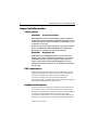
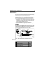
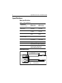
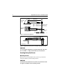
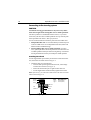
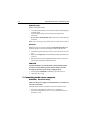
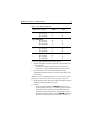
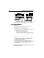
Distributed by
Any reference to Raytheon or
RTN in this manual should be
interpreted as Raymarine.
The names Raytheon and RTN
are owned by the
Raytheon Company.
Hydraulic Linear
Drive
Installation Guide
Drives covered:
M81200
Type 2 Hydraulic Linear Drive 12 V
M81201
Type 2 Hydraulic Linear Drive 24 V
M81202
Type 3 Hydraulic Linear Drive 12 V
M81203
Type 3 Hydraulic Linear Drive 24 V
Document number: 81177-3
March 2001
2
Hydraulic Linear Drive - Installation Guide
Important information
Safety notices
WARNING:
Product installation
This equipment must be installed and operated in accordance
with the instructions contained in this handbook. Failure to do so
could result in poor product performance, personal injury and/
or damage to your boat.
Because correct performance of the boat’s steering is critical for
safety, we STRONGLY RECOMMEND that an Authorized
Raymarine Service Representative fits this product.
WARNING:
Navigation aid
Although we have designed this product to be accurate and
reliable, many factors can affect its performance. As a result, it
should only be used as an aid to navigation and should never
replace commonsense and navigational judgement. Always
maintain a permanent watch so you can respond to situations as
they develop.
EMC conformance
All Raymarine equipment and accessories are designed to the best
industry standards for use in the recreational marine environment.
The design and manufacture of Raymarine equipment and
accessories conform to the appropriate Electromagnetic
Compatibility (EMC) standards, but correct installation is required to
ensure that performance is not compromised.
Handbook information
To the best of our knowledge, the information in this handbook was
correct when it went to press. However, Raymarine cannot accept
liability for any inaccuracies or omissions it may contain. In addition,
our policy of continuous product improvement may change
specifications without notice. As a result, Raymarine cannot accept
liability for any differences between the product and the handbook.
© Raymarine Ltd 2001.
Hydraulic Linear Drive - Installation Guide
3
Introduction
Welcome to the installation guide for the Raymarine hydraulic linear
drive system. This product is intended to operate the boat’s steering
mechanism as part of a Raymarine autopilot system.
The hydraulic linear drive system is designed for boats with existing
mechanical steering systems, not hydraulic steering systems. It
provides a totally isolated autopilot steering system consisting of:
•
Hydraulic ram: a self-contained autopilot steering cylinder with a
load limiting system and a built in clutch (to allow friction-free
steering when the autopilot is not in use).
Reversing hydraulic pump: powers the hydraulic ram.
Hydraulic fluid reservoir: supplies hydraulic fluid to the system.
•
•
CAUTION:
The ram drives the rudder directly from the tiller arm or rudder
quadrant. Before installing this drive unit, check that the boat’s
steering system can be backdriven from the rudder.
Reservoir
Reservoir clip
Reservoir pipe
Pump
Motor cables
Tie-wrap
Ram pipe
Tap
Pump pipes
Mounting foot
Ram
Push rod
Clutch cable
Rod end
D5088-1
Figure 1: Main components of the hydraulic linear drive system
Contents
1
Product specifications
page 4
2
Installation instructions
page 5
3
Maintenance information
page 15
4
Hydraulic Linear Drive - Installation Guide
Specifications
Ram specifications
Table 1: Ram specifications
Performance
(at nominal voltage)
Type 2 (T2)
M81200 (12 V)
M81201 (24 V)
Type 3 (T2)
M81202 (12 V)
M81203 (24 V)
Maximum boat
displacement
22,000 kg
(48,500 lb)
35,000 kg
(77,000 lb)
Peak thrust
585 kg
(1,290 lb)
1,000 kg
(2,200 lb)
Maximum stroke
254 mm
(10 in)
300 mm
(12 in)
Hardover to hardover time
(+/- 35º, no load)
10 sec
12 sec
Maximum rudder torque
1,270 Nm
(11,300 lb.in)
2,565 Nm
(23,100 lb.in)
Other information
(applies to Types 2 and 3)
protected for use in engine compartments
CE approvals - conforms to:
89/336/EC (EMC), EN60945:1997
94/25/EC (RCD), EN28846:1993
Ram dimensions
A (mid stroke)
101.6 mm (4 in)
152 mm (6 in)
80 mm
(3.15 in)
457 mm (18 in)
4 fixing holes for
8 mm (0.3125 in) bolts
Drive
Type 2
Type 3
Figure 2: Ram dimensions
A (mid stroke)
540 mm (21.25 in)
690 mm (27.15 in)
D5093-1
Hydraulic Linear Drive - Installation Guide
5
Installation instructions
Parts required
To install this drive you will need:
•
Parts supplied:
• pre-filled and pre-bled system consisting of: hydraulic ram;
hydraulic pump; hydraulic pipes; fluid reservoir (supplied
fitted with transit cap; standard cap also supplied)
• hydraulic fluid (to fill reservoir)
• tiller pin assembly (see Figure 7) consisting of: tiller pin,
R-clip, top washer, lock washer, nut (UNC nylock)
Additional parts:
• suitable securing bolts and lock washers/lock nuts for the
hydraulic ram and pump (see page 9)
• suitable cable and electrical connectors for the drive motor
and clutch (see page 12)
•
Note: Make sure you have obtained these additional parts before you
start installation.
Installation steps
WARNING: Electrical safety
Make sure you have switched off the power supply before you
start installing this product.
Follow these steps to install your hydraulic linear drive system:
1
Consult the EMC installation guidelines.
page 6
Ï
2
Mount the drive system components.
page 7
Ï
3
Connect to the course computer.
page 12
Ï
4
Complete the post-installation check.
page 14
6
Hydraulic Linear Drive - Installation Guide
1. EMC installation guidelines
All Raymarine equipment and accessories are designed to the best
industry standards for use in the recreational marine environment.
Their design and manufacture conforms to the appropriate
Electromagnetic Compatibility (EMC) standards, but correct
installation is required to ensure that performance is not
compromised. Although every effort has been taken to ensure that
they will perform under all conditions, it is important to understand
what factors could affect the operation of the product.
The guidelines given here describe the conditions for optimum EMC
performance, but it is recognized that it may not be possible to meet
all of these conditions in all situations. To ensure the best possible
conditions for EMC performance within the constraints imposed by
any location, always ensure the maximum separation possible
between different items of electrical equipment.
For optimum EMC performance, it is recommended that wherever
possible:
•
•
•
•
Raymarine equipment and cables connected to it are:
• At least 3 ft (1 m) from any equipment transmitting or cables
carrying radio signals e.g. VHF radios, cables and antennas.
In the case of SSB radios, the distance should be increased to
7 ft (2 m).
• More than 7 ft (2 m) from the path of a radar beam. A radar
beam can normally be assumed to spread 20 degrees above
and below the radiating element.
The equipment is supplied from a separate battery from that used
for engine start. Voltage drops below 10 V, and starter motor
transients, can cause the equipment to reset. This will not damage
the equipment, but may cause the loss of some information and
may change the operating mode.
Raymarine specified cables are used. Cutting and rejoining these
cables can compromise EMC performance and must be avoided
unless doing so is detailed in the installation manual.
If a suppression ferrite is attached to a cable, this ferrite should not
be removed. If the ferrite needs to be removed during installation
it must be reassembled in the same position.
Hydraulic Linear Drive - Installation Guide
7
Suppression ferrites
The following illustration shows typical cable suppression ferrites
used with Raymarine equipment. Always use the ferrites supplied by
Raymarine.
D3548-2
Figure 3: Typical Suppression Ferrites
Connections to other equipment
If your Raymarine equipment is to be connected to other equipment
using a cable not supplied by Raymarine, a suppression ferrite MUST
always be attached to the cable near to the Raymarine unit.
2. Mounting the drive components
Mounting the drive components involves four main steps:
•
•
•
•
ensuring correct hydraulic ram alignment
securing the hydraulic ram to the boat
connecting the hydraulic ram to the steering system
installing the other parts of the drive system
Ram alignment
When mounting the hydraulic ram, check that it is aligned correctly:
•
•
•
The ram must be at right angles to the mounting surface (see
Figure 4).
The ram must be at right angles to the tiller arm when the rudder is
amidships (see Figure 4).
The push rod must be accurately aligned with the tiller arm plane
of rotation. The ball end fitting only allows up to 5 degrees
misalignment between the push rod and tiller arm plane of
rotation (see Figure 5).
8
Hydraulic Linear Drive - Installation Guide
A (mid stroke)
View from
astern
90º
Drive
Type 2
Type 3
A (mid stroke)
540 mm (21.25 in)
690 mm (27.15 in)
B (tiller arm radius)
180 mm (7.1 in)
267 mm (10.5 in)
View from
above
90º
aft
B (tiller arm
radius)
D5091-1
Figure 4: Hydraulic ram alignment
5º Max.
5º Max.
View from astern
D5092-1
Figure 5: Alignment between push rod and tiller arm plane of rotation
CAUTION:
Accurate angular alignment is extremely important. You must
not exceed this +/- 5 degree limit under any circumstances.
Securing the hydraulic ram
Mounting location
Before you secure the hydraulic ram to your boat, you must first
check the suitability of the mounting location.
CAUTION:
Consult the boat manufacturer if you have any doubt about the
strength or suitability of the mounting location.
Hydraulic Linear Drive - Installation Guide
•
•
•
•
9
Structural strength:
• This drive produces a considerable amount of force, so you
must mount it on a solid structure (i.e. a substantial frame
member) in the boat. In some cases it may be necessary to
build a specially strengthened frame to mount the drive unit.
• To prevent excess noise and vibration, do not attach this drive
to any structures that support cabins.
Drive orientation:
• You must mount the hydraulic ram horizontally with its
mounting foot on a horizontal surface (see Figure 6). The
swivel joint does not have sufficient movement to position the
mounting foot vertically.
General position:
• Refer to the EMC installation guidelines (page 6)
• Make sure the drive will be accessible for future servicing.
Environment:
• This drive is not waterproof, so you should mount it in a dry
location, clear of any bilge water.
View from above
aft
View from above
aft
D5089-1
Figure 6: Drive orientation
Securing bolts
Attach the mounting foot with four stainless steel M8 (5/16 inch) bolts
and lock nuts/lock washers.
Note: Always mount the hydraulic ram as securely as possible to
make sure it performs reliably and remains correctly aligned.
10
Hydraulic Linear Drive - Installation Guide
Connecting to the steering system
CAUTION:
Consult the steering gear manufacturer if you have any doubt
about the strength of the existing tiller arm or rudder quadrant.
This drive produces a considerable amount of force, so you must
ensure that your tiller arm or rudder quadrant can cope with the peak
thrust specified in the Table 1, Ram specifications
Use one of these methods to attach the push rod to the rudder stock:
1. Independent tiller arm: we recommend that you attach the push
rod to the rudder stock via an independent tiller arm (Edson and
Whitlock offer a standard fitting).
2. Steering linkage tiller arm or rudder quadrant: in certain
cases, you may be able to attach the push rod to the same tiller arm
or rudder quadrant used by the main steering linkage. Consult the
steering manufacturer before you modify the rudder quadrant.
Attaching the rod end
Use the supplied tiller pin assembly to attach the rod end to the tiller
arm, at the tiller arm radius shown in Figure 4.
1. Attach the tiller pin to the tiller arm:
• insert the tiller pin through the tiller arm hole, so the flange
remains above the arm (see Figure 7)
• make sure that the tiller pin is a tight fit in the tiller arm
• use the supplied lock washer and fully tighten the lock nut
Note: If necessary, you will need to drill a hole in the tiller arm at the
radius shown in Figure 4.
R-clip
Washer
Drive
Type 2
Type 3
Rod end
Hole diameter 'X'
13 mm (0.52 in)
20 mm (0.78 in)
Flange
Tiller arm
Lock nut
Lock
washer
Tiller pin
X
D5090-1
Figure 7: Attaching the push rod to the tiller arm
Hydraulic Linear Drive - Installation Guide
11
2. Attach the rod end to the tiller pin:
• place the rod end onto the tiller pin
• secure with the supplied washer and R-clip (see Figure 7)
Steering check
When you have mounted the ram, turn the boat’s steering wheel from
hardover to hardover and check that:
•
•
•
Angular movement of the ball end fitting is less than 5 degrees
(see Figure 5). If you exceed this 5 degree limit, the drive will
catch on the tiller arm/rudder quadrant and the ball joint will bind.
No part of the drive unit fouls the boat’s structure when the push
rod moves in and out.
The total rudder movement is limited to +/- 35 degrees by the
steering system end stops rather than the linear drive’s end limits
(see Figure 8).
Steering system
end stop
Steering system
end stop
35º
35º
D5079-1
Figure 8: Total rudder movement
CAUTION:
Make sure rudder movement is limited by the steering system
end stops before the push rod reaches its end stop. Failure to do
this could damage the drive and will invalidate the warranty.
Installing the other parts of the system
Note: To make installation easier, we supply the hydraulic linear
drive system pre-plumbed, pre-filled with hydraulic fluid and
pre-bled, with just the reservoir empty. As a result you should not
need to bleed the system during installation. If you do need to
disconnect the pipes for any reason, contact Raymarine Technical
Services Call Center for advice on bleeding the system.
12
Hydraulic Linear Drive - Installation Guide
Hydraulic pump
Mount the hydraulic pump:
•
•
•
on a substantial member to avoid vibration that could damage the
hydraulic pipes
on a horizontal surface, clear of water spray and possible
immersion.
level or above the hydraulic ram to prevent air from collecting
in the ram
Note: Secure the pump using suitable bolts, lock nuts & lock washers.
Reservoir
Mount the reservoir vertically and at least 150 mm (6 in) above the
hydraulic pump (to ensure a good supply of fluid to the system):
1. Attach the clip, then use the tie-wrap to secure the reservoir to the
clip.
2. Remove the temporary (non-breathable) transit cap fitted to the
reservoir.
3. Fill the reservoir with the supplied hydraulic fluid, so the level is
between the minimum and maximum lines.
CAUTION:
Absolute cleanliness is essential when working with hydraulic
systems. Even the smallest particle of dirt could prevent the
steering system check valves from working properly.
4. Fit the supplied standard (breathable) cap to the reservoir.
5. Open the reservoir tap.
3. Connecting to the course computer
WARNING: Electrical safety
Make sure the power supply is switched off before you make any
electrical connections.
The hydraulic linear drive system has electrical connections for:
•
•
the motor in the pump: two cables: red (+) and black (-)
the clutch in the hydraulic ram: a two-core cable with brown (+)
and blue (-) cores
Hydraulic Linear Drive - Installation Guide
13
Table 2: Recommended cable sizes
Cable length
(pump to course computer)
Cable gauge
(AWG)
Copper area
(mm2)
Type 2 drive 12 V
up to 5 m (16 ft)
up to 7 m (23 ft)
up to 16 m (52 ft)
10
8
6
6
10
16
Type 2 drive 24 V
up to 3 m (10 ft)
up to 5 m (16 ft)
up to 10 m (32 ft)
up to 16 m (52 ft)
12
10
8
6
4
6
10
16
Type 3 drive 12 V
up to 5 m (16 ft)
up to 7 m (23 ft)
up to 16 m (52 ft)
8
6
4
10
16
25
Type 3 drive 24 V
up to 5 m (16 ft)
up to 7 m (23 ft)
up to 16 m (52 ft)
10
8
6
6
10
16
Connect the pump and ram to the course computer:
1. Measure the distance of cable run from the pump and ram to the
course computer:
• use Table 2 to identify the appropriate motor cable sizes
• use at least 1.5 mm2 (16 AWG) copper cable for the clutch
2. Join these cables to the ones on the pump and ram using
appropriate electrical connectors or junction boxes at the correct
power rating.
Note: To meet current EMC legislation, you must NOT untwist the
pump cables, and you must NOT remove the suppression ferrite.
3. Route the cables back to the course computer, taking into account
the EMC installation guidelines (page 6).
4. Connect:
• the cables from the pump to the MOTOR terminals on the
course computer (see Figure 9): at this stage you can connect
either motor cable to either terminal. You will check these
connections after installing the rest of the autopilot system.
• the cables from the hydraulic ram to the CLUTCH terminals on
the course computer (see Figure 9): brown (+) and blue (-)
14
Hydraulic Linear Drive - Installation Guide
OFF
SWITCH
– +
A B
POWER MOTOR
– –
– +
SOLENOID CLUTCH
Type 150/400 course computer
– +
lk CLUTCH
– +
1
2
POWER MOTOR
Type 100/300 course computer
D5080-1
Figure 9: Cable connections at course computer
4. Post-installation check
WARNING:
Keep clear of moving steering systems at all times. Protect
moving parts from access during normal use.
Check the following points after installing the drive:
1. Is the mounting foot secured to a substantial structure on the boat?
2. Is the hydraulic ram correctly aligned, i.e:
• Is the mounting foot correctly oriented?
• Is the drive mounted at right angles to the tiller arm, in a midstroke position, when the rudder is amidships?
• Is the push rod accurately aligned with the tiller arm plane of
rotation (deviation less than 5 degrees)?
3. Is the hydraulic ram rod end:
• securely attached to the tiller arm or quadrant?
• attached at the recommended tiller arm radius for the boat?
4. Are the motor and clutch cables correctly routed and securely
connected to the course computer?
5. Are all hydraulic pipes securely connected, with no leaks?
6. Have you filled the reservoir, fitted the standard cap and opened
the reservoir tap?
7. Have you completed a hand-steering check (see page 11)?
Note: When you have installed the entire autopilot system, you will
need to complete an autopilot steering check. Refer to the control unit
handbook for more details.
Hydraulic Linear Drive - Installation Guide
15
Maintenance
On a regular basis:
•
•
•
•
check all connection and mountings are secure
check hydraulic ram alignment
check pipes and cables for any signs of wear or damage
check hydraulic pipes and joints for leaks
EMC servicing and safety guidelines
•
•
•
•
•
Raymarine equipment should be serviced only by authorized
Raymarine service technicians. They will ensure that service
procedures and replacement parts used will not affect
performance. There are no user serviceable parts in any
Raymarine product.
Some products generate high voltages, so never handle the cables
or connectors when power is being supplied to the equipment.
When powered up, all electrical equipment produces
electromagnetic fields. These can cause adjacent pieces of
electrical equipment to interact with one another, with a
consequent adverse effect on operation. In order to minimize
these effects and enable you to get the best possible performance
from your Raymarine equipment, guidelines are given in the
installation instructions, to enable you to ensure minimum
interaction between different items of equipment, i.e. ensure
optimum Electromagnetic Compatibility (EMC).
Always report any EMC-related problem to your nearest
Raymarine dealer. We use such information to improve our
quality standards.
In some installations, it may not be possible to prevent the
equipment from being affected by external influences. In general
this will not damage the equipment but it can lead to spurious
resetting action, or momentarily may result in faulty operation.
Product support
Raymarine products are supported by a worldwide network of
distributors and Authorized Service Representatives. If you
encounter any difficulties with this product, please contact either
your national distributor, or your service representative, or the
Raymarine Technical Services Call Center. Refer to the back cover
or the Worldwide Distributor List for contact details.
16
Raymarine Ltd
Anchorage Park
Portsmouth, Hampshire
England PO3 5TD
Telephone +44 (0)23 9269 3611
Fax +44 (0)23 9269 4642
www.raymarine.com
Hydraulic Linear Drive - Installation Guide
Raymarine Inc
22 Cotton Road, Suite 280
Nashua
NH 03063-4219, USA
Telephone +1 603 881 5200
Fax +1 603 864 4756
www.raymarine.com
Raymarine Technical Services Call Center
UK: +44 (0)23 9271 4713 or
USA: +1 603 881 5200 or
+44 (0)23 9269 3611 ext. 1083
1-800-539-5539 ext. 2333