1
RB SERIES
Digital Temperature Controller
RB100/RB400
RB500/RB700
RB900
Communication
Instruction Manual
®
RKC INSTRUMENT INC.
IMR02C16-E3
z Modbus is a registered trademark of Schneider Electric.
z Company names and product names used in this manual are the trademarks or registered trademarks of
the respective companies.
All Rights Reserved, Copyright 2008, RKC INSTRUMENT INC.
Thank you for purchasing this RKC instrument. In order to achieve maximum performance and ensure
proper operation of your new instrument, carefully read all the instructions in this manual. Please place the
manual in a convenient location for easy reference.
SYMBOLS
WARNING : This mark indicates precautions that must be taken if there is danger of electric
shock, fire, etc., which could result in loss of life or injury.
CAUTION
!
: This mark indicates that if these precautions and operating procedures are not taken,
damage to the instrument may result.
: This mark indicates that all precautions should be taken for safe usage.
: This mark indicates important information on installation, handling and operating
procedures.
: This mark indicates supplemental information on installation, handling and
operating procedures.
: This mark indicates where additional information may be located.
!
WARNING
z An external protection device must be installed if failure of this instrument
could result in damage to the instrument, equipment or injury to personnel.
z All wiring must be completed before power is turned on to prevent electric
shock, fire or damage to instrument and equipment.
z This instrument must be used in accordance with the specifications to
prevent fire or damage to instrument and equipment.
z This instrument is not intended for use in locations subject to flammable or
explosive gases.
z Do not touch high-voltage connections such as power supply terminals, etc.
to avoid electric shock.
z RKC is not responsible if this instrument is repaired, modified or
disassembled by other than factory-approved personnel. Malfunction can
occur and warranty is void under these conditions.
IMR02C16-E3
i-1
CAUTION
z This product is intended for use with industrial machines, test and measuring equipment.
(It is not designed for use with medical equipment and nuclear energy.)
z This is a Class A instrument. In a domestic environment, this instrument may cause radio
interference, in which case the user may be required to take additional measures.
z This instrument is protected from electric shock by reinforced insulation. Provide reinforced
insulation between the wire for the input signal and the wires for instrument power supply,
source of power and loads.
z Be sure to provide an appropriate surge control circuit respectively for the following:
- If input/output or signal lines within the building are longer than 30 meters.
- If input/output or signal lines leave the building, regardless the length.
z This instrument is designed for installation in an enclosed instrumentation panel. All
high-voltage connections such as power supply terminals must be enclosed in the
instrumentation panel to avoid electric shock by operating personnel.
z All precautions described in this manual should be taken to avoid damage to the instrument or
equipment.
z All wiring must be in accordance with local codes and regulations.
z All wiring must be completed before power is turned on to prevent electric shock, instrument
failure, or incorrect action.
The power must be turned off before repairing work for input break and output failure including
replacement of sensor, contactor or SSR, and all wiring must be completed before power is
turned on again.
z To prevent instrument damage or failure, protect the power line and the input/output lines from
high currents with a protection device such as fuse, circuit breaker, etc.
z Prevent metal fragments or lead wire scraps from falling inside instrument case to avoid
electric shock, fire or malfunction.
z Tighten each terminal screw to the specified torque found in the manual to avoid electric shock,
fire or malfunction.
z For proper operation of this instrument, provide adequate ventilation for heat dispensation.
z Do not connect wires to unused terminals as this will interfere with proper operation of the
instrument.
z Turn off the power supply before cleaning the instrument.
z Do not use a volatile solvent such as paint thinner to clean the instrument. Deformation or
discoloration will occur. Use a soft, dry cloth to remove stains from the instrument.
z To avoid damage to instrument display, do not rub with an abrasive material or push front
panel with a hard object.
z When high alarm with hold action/re-hold action is used for Event function, alarm does not turn
on while hold action is in operation. Take measures to prevent overheating which may occur if
the control device fails.
NOTICE
z This manual assumes that the reader has a fundamental knowledge of the principles of electricity,
process control, computer technology and communications.
z The figures, diagrams and numeric values used in this manual are only for purpose of illustration.
z RKC is not responsible for any damage or injury that is caused as a result of using this instrument,
instrument failure or indirect damage.
z RKC is not responsible for any damage and/or injury resulting from the use of instruments made by
imitating this instrument.
z Periodic maintenance is required for safe and proper operation of this instrument. Some components
have a limited service life, or characteristics that change over time.
z Every effort has been made to ensure accuracy of all information contained herein. RKC makes no
warranty expressed or implied, with respect to the accuracy of the information. The information in this
manual is subject to change without prior notice.
z No portion of this document may be reprinted, modified, copied, transmitted, digitized, stored,
processed or retrieved through any mechanical, electronic, optical or other means without prior written
approval from RKC.
i-2
IMR02C16-E3
CONTENTS
Page
1. OUTLINE ............................................................................... 1
2. SPECIFICATIONS ................................................................ 3
3. WIRING ................................................................................. 5
3.1 Wiring for Host Communication ....................................................................... 5
3.1.1 Communication terminal number and signal details ................................................... 5
3.1.2 Wiring method ............................................................................................................ 6
3.2 Connections for Loader Communication ......................................................... 8
4. SETTING ............................................................................... 9
4.1 Display Sequence............................................................................................ 9
4.2 Description of Each Parameters [Function block 60 (F60.)] ................................... 10
4.3 Setting Procedure Example ........................................................................... 11
4.4 Communication Requirements ...................................................................... 15
5. RKC COMMUNICATION PROTOCOL ............................... 17
5.1 Polling ............................................................................................................ 17
5.1.1 Polling procedures ................................................................................................... 18
5.1.2 Polling procedure example (When the host computer requests data) ...................... 21
5.2 Selecting ........................................................................................................ 23
5.2.1 Selecting procedures ............................................................................................... 23
5.2.2 Selecting procedure example (When the host computer sends the set values) ....... 26
5.3 RKC Communication Identifier List ................................................................ 27
IMR02C16-E3
i-3
Page
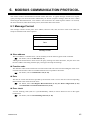
6. MODBUS COMMUNICATION PROTOCOL ....................... 45
6.1 Message Format............................................................................................ 45
6.2 Function Code ............................................................................................... 46
6.3 Communication Mode .................................................................................... 46
6.4 Slave Responses ........................................................................................... 47
6.5 Calculating CRC-16 ....................................................................................... 48
6.6 Register Read and Write ............................................................................... 51
6.6.1 Read holding registers [03H] .................................................................................... 51
6.6.2 Preset single register [06H] ...................................................................................... 52
6.6.3 Diagnostics (Loopback test) [08H] ........................................................................... 53
6.7 Caution for Handling Communication Data ................................................... 54
6.8 Modbus Communication Data List ................................................................. 55
7. TROUBLESHOOTING ........................................................ 71
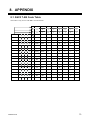
8. APPENDIX .......................................................................... 73
8.1 ASCII 7-Bit Code Table ................................................................................. 73
8.2 Deviation Action, Input Value Action and Set Value Action ........................... 74
i-4
IMR02C16-E3
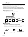
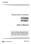
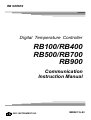
1. OUTLINE
The communication function makes it possible to monitor and set the data of the Digital Temperature Controller
RB100/400/500/700/900 (hereafter called controller) from a computer. To perform communication between
the computer and controller, you must create a communication program.
The controller interfaces with the host computer via Modbus or RKC communication (ANSI X3.28-1976
subcategories 2.5 and A4) protocols. The communication interface used for both protocols is RS-485.
In addition, the controller is equipped standard with a loader communication connector. Therefore, loader
communication is possible. For reference purposes, the Modbus protocol identifies the host computer as
master, the controller as slave.
RKC communication and Modbus
One host computer (master) can communicate with up to 31 controllers.
Host computer (master)
RKC communication or Modbus (RS-485)
Controller (slave) maximum connections: Up to 31 controllers
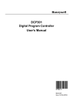
Loader communication
Loader communication allows controller data to be set from a personal computer.
By saving data that was set using our Communication Setup Tool WinUCI-B for RB series to a
computer, the data can be transferred to other controllers, allowing setup to be accomplished much more
quickly than when the data is set in each controller using the front panel keys. RKC USB
communication converter COM-K (sold separately) is required for the loader communication.
Personal computer
USB communication converter
COM-K
Controller
Maximum connections: 1 controller
The Loader port is only for parameter setup.
Loader communication can be used on a controller even when the communication function (optional)
is not installed.
IMR02C16-E3
1
1. OUTLINE
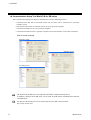
Communication Setup Tool WinUCI-B for RB series
The Communication Setup Tool WinUCI-B for RB series has the following features:
・Communication data such as measured values and set values can be monitored on a personal
computer screen.
・The communication data of controller can be set by the personal computer.
・Communication data can save to a personal computer.
・Communication data saved to a personal computer can be transferred to (set in) other controllers.
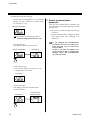
WinUCI screen example
Monitoring screen
Operation screen
SV setting screen
The WinUCI-B for RB series corresponds to the RKC communication protocol.
In addition, WinUCI-B for RB series can be used for both loader communication and host
communication.
The WinUCI-B for RB series can be downloaded from the RKC official website:
http://www.rkcinst.com/.
2
IMR02C16-E3
2. SPECIFICATIONS
RKC communication
Interface:
Based on RS-485, EIA standard
Connection method:
2-wire system, half-duplex multi-drop connection
Synchronous method:
Start-stop synchronous type
Communication speed: 2400 bps, 4800 bps, 9600 bps, 19200 bps
Data bit configuration: Start bit:
Data bit:
Parity bit:
Stop bit:
1
7 or 8
Without, Odd or Even
1 or 2
Protocol:
ANSI X3.28-1976 subcategories 2.5 and A4
RKC communication protocol
Polling/selecting type
Error control:
Vertical parity (With parity bit selected)
Horizontal parity (BCC check)
Communication code:
ASCII 7-bit code
Termination resistor:
Externally terminal connected (Example: 120 Ω 1/2 W)
Xon/Xoff control:
None
Maximum connections: Up to 31 controllers
Signal logic:
RS-485
Signal voltage
Logic
V (A) − V (B) ≥ 2 V
0 (SPACE)
V (A) − V (B) ≤ −2 V
1 (MARK)
Voltage between V (A) and V (B) is the voltage of (A) terminal
for the (B) terminal.
IMR02C16-E3
3
2. SPECIFICATIONS
Modbus
Interface:
Based on RS-485, EIA standard
Connection method:
2-wire system, half-duplex multi-drop connection
Synchronous method:
Start-stop synchronous type
Communication speed:
2400 bps, 4800 bps, 9600 bps, 19200 bps
Data bit configuration:
Start bit:
Data bit:
Parity bit:
Stop bit:
Protocol:
Modbus
1
8
Without, Odd or Even
1 or 2
Signal transmission mode: Remote Terminal Unit (RTU) mode
Function code:
03H (Read holding registers)
06H (Preset single register)
08H (Diagnostics: loopback test)
Error check method:
CRC-16
Error code:
1: Function code error
2: When the mismatched address is specified
3: When the specified number of data items in the query message exceeds
the maximum number of data items available
4: Self-diagnostic error response
Termination resistor:
Externally terminal connected (Example: 120 Ω 1/2 W)
Maximum connections:
Up to 31 controllers
Loader communication
Connection method:
Connection with a loader communication cable for RKC USB converter
COM-K (sold separately).
Synchronous method:
Start-stop synchronous type
Communication speed:
9600 bps
Data bit configuration:
Start bit:
Data bit:
Parity bit:
Stop bit:
1
8
Without
1
• The data bit configuration is fixed.
• The device address is fixed to “0.”
4
Protocol:
RKC communication protocol
(ANSI X3.28-1976 subcategories 2.5 and A4)
Maximum connections:
1 controller
IMR02C16-E3
3. WIRING
WARNING
!
To prevent electric shock or instrument failure, turn off the power before
connecting or disconnecting the instrument and peripheral equipment.
3.1 Wiring for Host Communication
The cable must be provided by the customer.
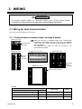
3.1.1 Communication terminal number and signal details
RB100 rear view
Make sure that lugs or unshielded cables of the communication
terminals are not touched to the screw heads, lugs, or unshielded
cables of the power supply terminals to prevent electric shock or
instrument failure.
Use additional care when two lugs are screwed to one
communication terminal.
Communication
terminals
Communication terminals
RB400 rear view
RB700 rear view
13 14 15
Communication
terminals
RB500 rear view
25
26
27
RB900 rear view
Communication
terminals
Communication terminals
RS-485
Terminal No.
RB100/400/500/900
13
IMR02C16-E3
RB700
25
Signal name
Symbol
Signal ground
SG
14
26
Send data/Receive data
T/R (A)
15
27
Send data/Receive data
T/R (B)
5
3. WIRING
3.1.2 Wiring method
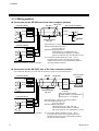
Connection to the RS-485 port of the host computer (master)
Controller (Slave)
RS-485
Paired wire
(−)
(+)
T/R (B)
T/R (B) 15 (27)
(+)
*R
Shielded twisted
pair wire
Controller (Slave)
SG 13 (25)
(+)
(−)
T/R (A)
T/R (A) 14 (26)
y
y
y
(−)
Host computer (Master)
SG
SG 13 (25)
T/R (A) 14 (26)
T/R (B) 15 (27)
*R
Maximum connections: Up to 31 controllers
Screw Size: M3 × 7 (with 5.8 × 5.8 square washer)
Recommended tightening torque:
0.4 N・m (4 kgf・cm)
Specified solderless terminals:
Manufactured by J.S.T MFG CO.,LTD.
Circular terminal with isolation V1.25-MS3
(M3 screw, width 5.5 mm, hole diameter 3.2 mm)
*R: Termination resistors (Example: 120 Ω 1/2 W)
If communication errors occur frequently due to the
operation environment or the communication distance,
connect termination resistors.
Connection to the RS-232C port of the host computer (master)
Use a RS-232C/RS-485 converter with an automatic send/receive transfer function.
Controller (Slave)
RS-485
SG 13 (25)
(−)
(+)
SG
T/R (A) 14 (26)
T/R (A)
T/R (B) 15 (27)
*R
Shielded twisted
pair wire
y
y
y
Controller (Slave)
SG 13 (25)
(−)
(+)
T/R (A) 14 (26)
T/R (B) 15 (27)
*R
Maximum connections: Up to 31 controllers
6
Host computer
(master)
Paired wire
RS-232C
T/R (B)
RS-232C/RS-485
converter
Recommended converter:
CD485, CD485/V manufactured by
Data Link, Inc. or equivalent.
Screw Size: M3 × 7 (with 5.8 × 5.8 square washer)
Recommended tightening torque:
0.4 N・m (4 kgf・cm)
Specified solderless terminals:
Manufactured by J.S.T MFG CO.,LTD.
Circular terminal with isolation V1.25-MS3
(M3 screw, width 5.5 mm, hole diameter 3.2 mm)
*R: Termination resistors (Example: 120 Ω 1/2 W)
If communication errors occur frequently due to the
operation environment or the communication distance,
connect termination resistors.
IMR02C16-E3
3. WIRING
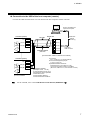
Connection to the USB of the host computer (master)
Connect the USB communication converter between the host computer and the controller.
Host computer (Master)
Connect to USB port of
a personal computer
Controller (Slave)
RS-485
Paired wire
SG 13 (25)
(−)
(+)
1 SG
T/R (A) 14 (26)
2 T/R (A)
T/R (B) 15 (27)
3 T/R (B)
4 Unused
Shielded twisted
pair wire
y
y
y
y
y
y
SG 13 (25)
(+)
Connect to
USB connector
5 Unused
COM-K
(The termination resistor is built into the COM-K.)
Controller (Slave)
(−)
USB cable
(COM-K
accessory)
T/R (A) 14 (26)
T/R (B) 15 (27)
Maximum connections:
Up to 31 controllers
Screw Size:
M3 × 7 (with 5.8 × 5.8 square washer)
Recommended tightening torque:
0.4 N・m (4 kgf・cm)
Specified solderless terminals:
Manufactured by J.S.T MFG CO.,LTD.
Circular terminal with isolation V1.25-MS3
(M3 screw, width 5.5 mm, hole diameter 3.2 mm)
*R: Termination resistors
(Example: 120 Ω 1/2 W)
If communication errors occur
frequently due to the operation
environment or the
communication distance,
connect termination resistors.
For the COM-K, refer to the COM-K Instruction Manual (IMR01Z01-E).
IMR02C16-E3
7
3. WIRING
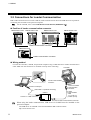
3.2 Connections for Loader Communication
RKC USB communication converter COM-K, loader communication cable and USB cable are required for
connecting this controller to the personal computer.
For the COM-K, refer to the COM-K Instruction Manual (IMR01Z01-E).
Position of loader communication connector
RB100 bottom view
RB400 bottom view
RB900 bottom view
RB700 bottom view
Loader communication connector
RB500 side view
Loader communication connector
Wiring method
Connect the controller, COM-K, and personal computer using a USB cable and a loader communication
cable. Make sure the connectors are oriented correctly when connecting.
Controller
Personal computer
Loader communication
connector
Connect to USB port
USB cable 1 m (COM-K accessory)
COM-K
Connect to USB connector
Connect to loader
communication
connector
Loader
communication
cable
1.5 m (W-BV-01)
[COM-K optional]
Connect to loader communication connector
When using the loader communication, USB driver for COM-K must be installed on the
personal computer.
The USB driver for COM-K can be downloaded the RKC official website:
http://www.rkcinst.com/.
8
IMR02C16-E3
4. SETTING
To establish communication parameters between host computer (master) and controller (slave), it is
necessary to set the device address (Modbus: Slave address), communication speed, data bit configuration
and interval time on each controller (slave) in the function block 60 (F60.) of engineering mode.
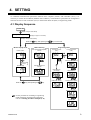
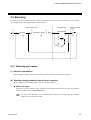
4.1 Display Sequence
Power ON
Display changes automatically
Input type/Input range display
(Display for approx. 4 seconds)
Display changes automatically
Press the
key while pressing the
Monitor display mode
Mode switching
PV/SV monitor
Auto (AUTO)/Manual (MAN)
transfer
Press the
Engineering mode
Function block 00
(F00.)
Three
times
2 seconds
or more
[STOP mode]
key for 4 seconds.
Function block 60
(F60.)
Communication protocol
Set data unlock/lock
transfer
key while pressing the
Mode selection
(no display)
Device address
RUN/STOP setting
Communication speed
key.
Data bit configuration
For the procedure for switching to engineering
mode and setting communication parameters,
refer to 4.3 Setting Procedure Example (P. 11).
IMR02C16-E3
Interval time
9
4. SETTING
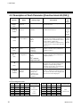
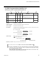
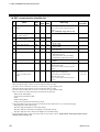
4.2 Description of Each Parameter [Function block 60 (F60.)]
Symbol
Name
F60.
Setting range
Function
block 60
Factory
set
value
Description
This is the first parameter symbol of
function block 60.
(F60.)
CMPS
Communication
protocol
0: RKC communication
1: Modbus
Use to select a protocol of
communication function.
Device address
(Slave address)
RKC communication:
0 to 99
Modbus:
1 to 99
Communication
speed
0: 2400 bps
1: 4800 bps
2: 9600 bps
3: 19200 bps
RKC communication:
0 to 11
Modbus:
0 to 5
Refer to Data bit
configuration table.
0 to 250 ms
Do not use the same device address for
more than one controller in multi-drop
connection. Each controller must have a
unique address in multi-drop
connection. In Modbus communication,
communication is not possible when the
address is 0.
Set the same communication speed for
both the controller (slave) and the host
computer (master).
(CMPS)
Add
(Add)
bPS
(bPS)
Data bit
configuration
bIT
(bIT)
Interval time
INT
(INT)
CMRM
(CMRM)
Communication
response
monitor
0: Normal response
1: Overrun error
2: Parity error
4: Framing error
8: Receive buffer
overflow
RKC
communication:
0*
Modbus:
1*
RKC
communication:
0
Modbus:
1
3
Set the same data bit configuration for
both the controller (slave) and the host
computer (master).
0
The interval time for the controller
should be set to provide a time for host
computer to finish sending all data
including stop bit and to switch the line
to receive status for the host.
When a communication error occurs, a
number is displayed to indicate the error
type. If two or more errors happen, the
sum of errors will be displayed.
10
* The communication protocol that was selected by means of the model code when the order was placed is set as the factory set
value.
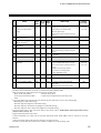
Data bit configuration table
10
Set
value
Data
bit
Parity
bit
Stop
bit
Settable
communication
Set
value
Data
bit
Parity
bit
Stop
bit
Settable
communication
0
1
2
3
4
5
8
8
8
8
8
8
Without
Without
Even
Even
Odd
Odd
1
2
1
2
1
2
RKC
communication
and
Modbus
6
7
8
9
10
11
7
7
7
7
7
7
Without
Without
Even
Even
Odd
Odd
1
2
1
2
1
2
RKC
communication
IMR02C16-E3
4. SETTING
Interval time:
The interval time for the controller should be set to provide a time for host computer to finish
sending all data including stop bit and to switch the line to receive status for the host.
If the interval time between the two is too short, the controller may send data before the host
computer is ready to receive it.
In this case, communication transmission cannot be conducted correctly.
The device address (slave address), communication speed, data bit configuration, and interval
time can also be set by loader communication using WinUCI-B for RB series.
4.3 Setting Procedure Example
This setting example shows the setting procedure when the controller settings are set to the factory set
values (the state when the controller power is initially turned on).
!
WARNING
Parameters in the Engineering mode (F21 to F70) should be set according to the
application before setting any parameter related to operation.
Once the parameters in the Engineering mode are set correctly, no further
changes need to be made to parameters for the same application under normal
conditions.
If they are changed unnecessarily, it may result in malfunction or failure of the
instrument.
RKC will not bear any responsibility for malfunction or failure as a result of
improper changes in the Engineering mode.
After all the communications parameters are set, perform one of the following steps to
make settings valid:
• The power is turned on again after turning it off once.
• The RUN/STOP mode is changed to RUN from STOP again after changing it to STOP
once.
If you have locked the controller setting data so that it cannot be changed, the lock must be
released before configuring the communication settings.
To release the lock, refer to RB series Quick Operation Manual (IMR02C39-E).
Press the SET key to store the new value. If the SET key is not pressed within 1 minute, the
display returns to the measured value (PV)/set value (SV) monitor screen and the set value
returns the previous setting.
For details on changing the numeric value, refer to RB series Quick Operation Manual
(IMR02C39-E).
Continued on the next page.
IMR02C16-E3
11
4. SETTING
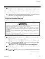
Continued from the previous page.
1. Turn on the power of the
controller.
Press the SET key to store the new set value.
The display goes to the RUN/STOP setting.
Mode selection
(no display)
RUN/STOP setting
2. Go to the engineering mode.
Press the <R/S key for 4 seconds while
pressing the SET key at PV/SV monitor until
Engineering mode is displayed.
PV/SV monitor
Engineering mode
(4 seconds or more)
3. Enable display of function
blocks 21 (F21.) to 91 (F91.).
Press the SET key three times at function block
00 (F00.) until Mode selection (no display) is
displayed.
Function block 00
(F00.)
When “128” is set, display of the parameters
from function block 21 (F21.) to function
block 91 (F91.) is enabled.
4. Set the controller to the STOP
state (control stop).
Set the RUN/STOP setting to “1: STOP.”
RUN/STOP setting
Mode selection
(no display)
(Three times)
Press the SET key to store the new set value.
The display goes to the function block 00
(F00.). The STOP lamp lights up and the
controller enters the STOP state.
Set the mode selection (no display) to “128.”
Mode selection
(no display)
RUN/STOP setting
Function block 00
(F00.)
STOP lamp lights (green)
12
IMR02C16-E3
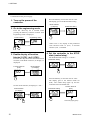
4. SETTING
5. Go to the function block 60
(F60.).
Press the DOWN key three times at function
block 00 (F00.) until function block 60 (F60.)
is displayed.
Function block 00
(F00.)
Press the SET key to store the new set value.
The display goes to the communication speed.
Device address
Communication speed
Function block 60
(F60.)
(Three times)
Set the communication speed.
Example: Setting the communication speed to
“2 (9600 bps).”
6. Set the communication
parameter.
Press the SET key twice at function block 60
(F60.) until device address is displayed.
Function block 60
(F60.)
Setting range: 0: 2400 bps
1: 4800 bps
2: 9600 bps
3: 19200 bps
Communication speed
Device address
(Press twice.)
Press the SET key to store the new set value.
The display goes to the data bit configuration.
Set the device address (slave address).
Example: Setting the device address (slave
address) to 1.
Communication speed
Data bit configuration
Setting range: 0 to 99 (RKC communication)
1 to 99 (Modbus)
Device address
Continued on the next page.
IMR02C16-E3
13
4. SETTING
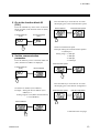
Continued from the previous page.
Set the data bit configuration. As an example,
factory set value “0 (data bit 8, without parity
bit, stop bit 1)” is set.
Data bit configuration
7. Enable communication
parameter
After all the communications parameters are
set, perform one of the following steps to make
settings valid:
• The power is turned on again after turning
it off once.
For details of setting range, refer to
Data bit configuration table (P. 10).
Press the SET key.
The display goes to the interval time.
Data bit configuration
Interval time
• The RUN/STOP mode is changed to RUN
from STOP again after changing it to
STOP once.
If you changed the communication
parameters, be sure to turn the power
OFF and then ON or switch from
STOP to RUN.
If this is not done, the higher level
device will not be able to recognize the
changed values and communication
may not be possible.
Set the interval time.
As an example, factory set value “10” is set.
Setting range: 0 to 250 ms
Interval time
Press the SET key.
The display goes to the communication
response monitor.
Interval time
14
Communication
response monitor
IMR02C16-E3
4. SETTING
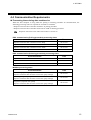
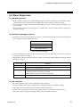
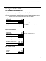
4.4 Communication Requirements
Processing times during data send/receive
When the host computer is using either the polling or selecting procedure for communication, the
following processing times are required for controller to send data:
- Response wait time after controller sends BCC in polling procedure
- Response wait time after controller sends ACK or NAK in selecting procedure
Response send time is time when interval time is set at 0 ms.
RKC communication (Polling procedure) processing times
Procedure details
Time
Response send time after controller receives ENQ
60 ms max.
Response send time after controller receives ACK
60 ms max.
Response send time after controller receives NAK
60 ms max.
Response send time after controller sends BCC
52 ms max.
RKC communication (Selecting procedure) processing times
Procedure details
Time
Response send time after controller receives BCC
65 ms max.
Response wait time after controller sends ACK
52 ms max.
Response wait time after controller sends NAK
52 ms max.
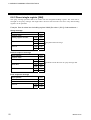
Modbus processing times
Procedure details
Time
Read holding registers [03H]
Response send time after the slave receives the query message
60 ms max.
Preset single register [06H]
Response send time after the slave receives the query message
65 ms max.
Diagnostics (loopback test) [08H]
Response send time after the slave receives the query message
IMR02C16-E3
60 ms max.
15
4. SETTING
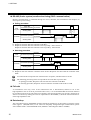
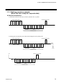
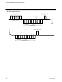
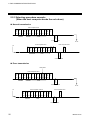
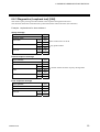
RS-485 (2-wire system) send/receive timing (RKC communication)
RS-485 communication is conducted through two wires, therefore, the transmission and reception of
data requires precise timing.
z Polling procedure
Host
computer
Controller
Possible
Send data
(Possible/Impossible) Impossible
Sending status
E
O
T
-----
E
N
Q
Possible
Send data
(Possible/Impossible) Impossible
A
C
K
a
b
S
T
X
Sending status
N
or A
K
-----
c
B
C
C
a: Response send time after the controller receives [ENQ] + Interval time
b: Response send time after the controller sends BCC
c: Response send time after the controller receives [ACK] + Interval time or
Response send time after the controller receives [NAK] + Interval time
z Selecting procedure
Host
computer
Possible
Send data
(Possible/Impossible) Impossible
Sending status
Controller
Possible
Send data
(Possible/Impossible) Impossible
Sending status
S
T
X
-----
B
C
C
a
b
A
N
C or A
K
K
a: Response send time after the controller receives BCC + Interval time
b: Response wait time after the controller sends ACK or Response wait time after the controller sends
NAK
To switch the host computer from transmission to reception, send data must be on line.
The following processing times are required for the controller to process data:
- In polling procedure, Response wait time after the controller sends BCC
- In selecting procedure, Response wait time after the controller sends ACK or NAK
Fail-safe
A transmission error may occur if the transmission line is disconnected, shorted or set to the
high-impedance state. In order to prevent the above error, it is recommended that the fail-safe function
be provided on the receiver side of the host computer. The fail-safe function can prevent a framing error
from its occurrence by making the receiver output stable to the MARK (1) when the transmission line is
in the high-impedance state.
Data backup
The nonvolatile memory (EEPROM) for data backup has limitations on the number of memory rewrite
times (approx. 1,000,000 times). If set values are frequently changed through communication, please
select “Buffer mode” in the EEPROM mode (Identifier: EB or Register address: 001BH).
16
IMR02C16-E3
5. RKC COMMUNICATION PROTOCOL
The controller uses the polling/selecting method to establish a data link.
The basic procedure is followed ANSI X3.28-1976 subcategories 2.5 and A4 basic mode data transmission
control procedure (Fast selecting is the selecting method used in this controller).
z The polling/selecting procedures are a centralized control method where the host computer controls
the entire process. The host computer initiates all communication so the controller responds according
to queries and commands from the host.
z The code use in communication is 7-bit ASCII code including transmission control characters. The
transmission control characters are EOT (04H), ENQ (05H), ACK (06H), NAK (15H), STX (02H)
and ETX (03H). The figures in the parenthesis indicate the corresponding hexadecimal number.
The RKC communication data transmission/reception status can be checked by using the
Communication Monitor Tool “WinUCI-A” and Communication Setup Tool
“WinUCI-B for RB series.”
The WinUCI-A and WinUCI-B for RB series can be downloaded from the official RKC
website: http://www.rkcinst.com/.
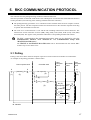
5.1 Polling
Polling is the action where the host computer requests one of the connected controllers to transmit data.
An example of the polling procedure is shown below:
Host computer send
E
O
T
E
[Address] [ ID ] N
Q
(1)
(2)
Controller send
Host
computer
send
Controller
send
E
O
T
No response
(5)
E
O
T (4)
S
E
T [ ID ] [ Data ] T [ BCC ]
X
X
(3)
Host
computer
send
(10)
No (8)
response
(9)
Time
out
E
O
T
Indefinite
A (6)
C
N
K
A
(7) K
ID: Identifier
IMR02C16-E3
17
5. RKC COMMUNICATION PROTOCOL
5.1.1 Polling procedures
(1) Data link initialization
Host computer sends EOT to the controllers to initiate data link before polling sequence.
(2) Data sent from host computer - Polling sequence
The host computer sends the polling sequence in the following formats:
1.
2.
Example:
3.
ENQ
0
2
M
1
ENQ
Address Identifier
1. Address (2 digits)
The device address specifies the controller to be polled and each controller must have its own
unique device address.
This data is a device address of the controller to be selected and must be the same as the device
address set value in item 4. SETTING (P. 9).
The polling address which transmitted a message once becomes effective so long as data
link is not initialized by transmit and receive of EOT.
2. Identifier (2 digits)
The identifier specifies the type of data that is requested from the controller. Always attach the
ENQ code to the end of the identifier.
For details, refer to 5.3 RKC Communication Identifier List (P. 27).
3. ENQ
The ENQ is the transmission control character that indicates the end of the polling sequence.
The ENQ must be attached to the end of the identifier.
The host computer then must wait for a response from the controller.
(3) Data sent from the controller
If the polling sequence is received correctly, the controller sends data in the following format:
1.
2.
STX
Identifier
3.
4.
5.
Data
ETX
BCC
1. STX
STX is the transmission control character which indicates the start of the text transmission
(identifier and data).
18
IMR02C16-E3
5. RKC COMMUNICATION PROTOCOL
2. Identifier (2 digits)
The identifier indicates the type of data (measured value, status and set value) sent to the host
computer.
For details, refer to 5.3 RKC Communication Identifier List (P. 27).
3. Data (6 digits)
Data indicated by the identifier belonging to the controller. It is expressed in decimal ASCII code
including a minus sign (-) and a decimal point. Data is not zero-suppressed.
The data of “Model codes: ID” has 32 digits.
The data of “ROM version monitor: VR” has 8 digits.
The data of remaining time monitor, timer 1, timer 2, timer 3, and timer 4 are as follows:
Punctuation of time unit is expressed in colon “: (3AH).”
Example: 0 hours and 01 minutes to 99 hours and 59 minutes, and 0 minutes and
01 seconds to 99 minutes and 59 seconds
00:01 to 99:59
4. ETX
ETX is a transmission control character used to indicate the end of text transmission.
5. BCC
BCC (Block Check Character) detects error by using horizontal parity (even number).
Calculation method of BCC: Exclusive OR all data and characters from STX through ETX, not
including STX.
Example:
STX
M
1
0
1
0
0
.
0
4DH 31H 30H 31H 30H 30H 2EH 30H
ETX
03H
BCC
Hexadecimal numbers
BCC=4DH ⊕ 31H ⊕ 30H ⊕ 31H ⊕ 30H ⊕ 30H ⊕ 2EH ⊕ 30H ⊕ 03H=60H
( ⊕: Exclusive OR)
Value of BCC becomes 60H.
(4) EOT sent from the controller (Ending data transmission from the controller)
In the following cases, the controller makes a timeout judgment after about 3 seconds, sends EOT,
and ends the data link:
• When the specified identifier is invalid
• When there is an error in the data type
• When all the data has been sent
(5) No response from the controller
The controller will not respond if the polling address is not received correctly. It may be necessary for
the host computer to take corrective action such as a time-out.
IMR02C16-E3
19
5. RKC COMMUNICATION PROTOCOL
(6) ACK (Acknowledgment)
An acknowledgment ACK is sent by the host computer when data received is correct.
When the controller receives ACK from the host computer, the controller will send any remaining
data of the next identifier without additional action from the host computer.
For the identifier, refer to 5.3 RKC Communication Identifier List (P. 27).
When host computer determines to terminate the data link, EOT is sent from the host computer.
(7) NAK (Negative acknowledge)
If the host computer does not receive correct data from the controller, it sends a negative
acknowledgment NAK to the controller. The controller will re-send the same data when NAK is
received. This cycle will go on continuously until either recovery is achieved or the data link is
corrected at the host computer.
(8) No response from host computer
When the host computer does not respond within approximately three seconds after the controller
sends data, the controller sends EOT to terminate the data link. (Time out: 3 seconds)
(9) Indefinite response from host computer
The controller sends EOT to terminate the data link when the host computer response is indefinite.
(10) EOT (Data link termination)
The host computer sends EOT message when it is necessary to suspend communication with the
controller or to terminate the data link due lack of response from the controller.
20
IMR02C16-E3
5. RKC COMMUNICATION PROTOCOL
5.1.2 Polling procedure example
(When the host computer requests data)
Normal transmission
(1) When the measured value (PV) monitor (identifier: M1) is polled
Host computer send
E
O
T
0
04H
30H
0
M
Host computer send
E
N
Q
1
30H 4DH 31H
E
O
T
05H
04H
S
T
X
Address Identifier
M
1
02H 4DH 31H
0
1
0
0
30H
31H
30H
.
0
30H 2EH 30H
E
T
X
B
C
C
03H
Data
Identifier
Controller send
(2) Polling the next identifier with ACK (acknowledgment) after polling ends
Host computer send
Host computer send
E
O
T
0
04H
30H
0
M
E
N
Q
1
30H 4DH 31H
A
C
K
05H
06H
S
T
X
Address Identifier
M
1
02H 4DH 31H
0
1
0
30H
31H
30H
Identifier
0
.
0
30H 2EH 30H
E
T
X
B
C
C
03H
To *1
Data
Controller send
Host computer send
*1
E
O
T
04H
S
T
X
M
2
02H 4DH 32H
Identifier
0
0
0
30H
30H
30H
1
.
0
31H 2EH 30H
E
T
X
B
C
C
03H
Data
Controller send
IMR02C16-E3
21
5. RKC COMMUNICATION PROTOCOL
Error transmission
Host computer send
E
O
T
0
04H
30H
0
Host computer send
E
N
Q
1
M
30H 4DH 31H
N
A
K
Error data
05H
15H
S
T
X
Address Identifier
M
1
02H 4DH 31H
0
1
0
30H
31H
30H
Identifier
0
,
0
30H 2CH 30H
E
T
X
B
C
C
03H
To *1
Data
Controller send
Host computer send
*1
E
O
T
04H
S
T
X
M
1
02H 4DH 31H
Identifier
0
1
0
30H
31H
30H
0
.
0
30H 2EH 30H
E
T
X
B
C
C
03H
Data
Controller re-send
22
IMR02C16-E3
5. RKC COMMUNICATION PROTOCOL
5.2 Selecting
Selecting is the action where the host computer requests one of the connected controllers to receive data.
An example of the selecting procedure is shown below:
Host computer send
E
O
T
[Address]
(1)
Controller send
E
S
T [Identifier] [Data] T [BCC]
X
X
(2)
Host computer
send
No response
(3)
(6)
A
C
K
(4)
N
A
K
(5)
E
O
T
(7)
5.2.1 Selecting procedures
(1) Data link initialization
Host computer sends EOT to the controllers to initiate data link before selecting sequence.
(2) Sending selecting address from the host computer
Host computer sends selecting address for the selecting sequence.
Address (2 digits)
This data is a device address of the controller to be selected and must be the same as the device
address set value in item 4. SETTING (P. 9).
As long as the data link is not initialized by sending or receiving EOT, the selecting
address once sent becomes valid.
IMR02C16-E3
23
5. RKC COMMUNICATION PROTOCOL
(3) Data sent from the host computer
STX
1.
2.
Identifier
Data
ETX
BCC
For the STX, ETX and BCC, refer to 5.1 Polling (P. 17).
1. Identifier (2 digits)
The identifier specifies the type of data that is requested from the controller, such as set value.
For details, refer to 5.3 RKC Communication Identifier List (P. 27).
2. Data
Data which is indicated by an identifier of the controller is expressed in decimal ASCII code
including a minus sign (-) and a decimal point. The channel number can be zero-suppressed.
The number of digits varies depending on the type of identifier. (Within 6 digits)
Set timer 1, timer 2, timer 3, and timer 4 as shown below.
Use “: (3AH) in ASCII 7 Bit Code Table” to divide hour from minute, or minute from
second.
Example: 0 hours and 01 minutes to 99 hours and 59 minutes, and 0 minutes and
01 seconds to 99 minutes and 59 seconds
00:01 to 99:59
z About numerical data
Numerical data which the controller can receive
• Data with numbers below the decimal point omitted or zero-suppressed data can be received.
(Number of digits: Within 6 digits)
<Example> When data send with −001.5, −01.5, −1.5, −1.50, −1.500 at the time of −1.5,
controller can receive data.
• When the host computer sends data containing a decimal point to an item without a decimal
point, the controller receives a message rounded down to the nearest whole number.
<Example> When setting range is 0 to 200, the controller will receive as follows:
Send data
0.5
100.5
Receive data
0
100
• The controller receives the value based on the decided number of places after decimal point.
Any number beyond the established number of decimal points will be cut off.
<Example> When setting range is −10.00 to +10.00, the controller will receives as follows:
Send data
−.5
−.058
.05
−0
Receive data
−0.50
−0.05
0.05
0.00
Numerical data which the controller can not receive
When the host computer sends abnormal character data, the controller returns NAK as a response.
<Example> Only minus sign (there is no figure)
Only decimal point (period)
24
IMR02C16-E3
5. RKC COMMUNICATION PROTOCOL
(4) ACK (Acknowledgment)
An acknowledgment ACK is sent by the controller when data received is correct. When the host computer
receives ACK from the controller, the host computer will send any remaining data. If there is no more data
to be sent to the controller, the host computer sends EOT to terminate the data link.
(5) NAK (Negative acknowledge)
If the controller does not receive correct data from the host computer, it sends a negative acknowledgment
NAK to the host computer. Corrections, such as re-send, must be made at the host computer. The controller
will send NAK in the following cases:
• When an error occurs on communication the line (parity, framing error, etc.)
• When a BCC check error occurs
• When the specified identifier is invalid
• When receive data exceeds the setting range
• When receive data is the identifier of RO (read only)
(6) No response from controller
The controller does not respond when it cannot receive the selecting address, STX, ETX or BCC.
(7) EOT (Data link termination)
The host computer sends EOT when there is no more data to be sent from the host computer or there is no
response from the controller.
IMR02C16-E3
25
5. RKC COMMUNICATION PROTOCOL
5.2.2 Selecting procedure example
(When the host computer sends the set values)
Normal transmission
Host computer send
E
O
T
0
0
S
T
X
S
1
0
1
0
04H
30H
30H
02H
53H
31H
30H
31H
30H
Address
Identifier
0
.
E
T
X
0
30H 2EH 30H
B
C
C
03H
A
C
K
Data
06H
Controller send
Host computer send
Host computer send
*1
S
T
X
A
1
0
0
5
02H
41H
31H
30H
30H
35H
Identifier
0
To *1
.
E
T
X
0
30H 2EH 30H
B
C
C
E
O
T
03H
04H
A
C
K
Data
06H
Controller send
Error transmission
Error data
Host computer send
E
O
T
0
0
S
T
X
S
1
0
1
0
04H
30H
30H
02H
53H
31H
30H
31H
30H
Address
0
,
E
T
X
0
30H 2CH 30H
B
C
C
03H
N
A
K
Data
Identifier
15H
Controller send
Host computer send
Host computer re-send
*1
S
T
X
S
1
0
1
0
02H
53H
31H
30H
31H
30H
Identifier
0
.
0
30H 2EH 30H
Data
To *1
E
T
X
B
C
C
E
O
T
03H
04H
A
C
K
06H
Controller send
26
IMR02C16-E3
5. RKC COMMUNICATION PROTOCOL
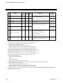
5.3 RKC Communication Identifier List
Reference to RKC communication identifier list
(1)
No.
1
(2)
(3)
(4)
(5)
RKC
of AttriIden- No.
digits
bute
tifier
Name
Measured value (PV)
monitor
M1
6
RO
2
Current transformer 1
(CT1) input value monitor 1
M2
6
RO
3
Current transformer 2
(CT2) input value monitor 1
M3
6
RO
(6)
Data range
Factory
set value
Within input range
Varies with the setting of the Decimal point
position.
Refer to Input range table (P. 42).
0.0 to 100.0 A
(1) Name:
Communication data name
(2) RKC identifier:
Communication identifier of RKC communication
(3) No. of digits:
The number of maximum digits
(4) Attribute:
A method of how communication data items are read or written when viewed
from the host computer is described
RO:
Read only data
Host computer
Data direction
Controller
R/W: Read and Write data
Host computer
(5) Data range:
Data direction
Controller
Read or write range of communication data
RKC communication
ASCII code data of 7 digits
Most significant digit ………… Least significant digit
(6) Factory set value: Factory set value of communication data
For details of data, refer to the RB series Instruction Manual (IMR02C15-E).
For data corresponding to No. 89 to 146 (other than No. 102 AO full scale adjustment
value and No. 103 AO zero adjustment value), its attribute becomes RO (Only reading
data is possible) during RUN (control).
When setting data corresponding to No. 89 to 146 (other than No. 102 and No. 103),
write the data after STOP (control stop) is selected.
IMR02C16-E3
27
5. RKC COMMUNICATION PROTOCOL
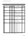
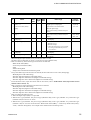
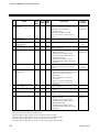
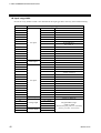
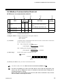
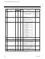
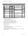
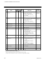
RKC communication identifier list
No.
Name
1 Measured value (PV)
monitor
RKC
No. of AttriIdenData range
digits bute
tifier
M1
6
RO Within input range
Factory
set value
Varies with the setting of the Decimal point
position.
2 Current transformer 1 (CT1)
input value monitor 1
3 Current transformer 2 (CT2)
input value monitor 1
4 Event 1 state monitor 2
M2
6
RO
M3
6
RO
AA
6
RO
5 Event 2 state monitor 3
AB
6
6 Burnout state monitor
B1
6
7 Error code
ER
6
8 RUN/STOP transfer
SR
6
9 Set value 1 (SV1)
S1
6
Refer to Input range table (P. 42).
0.0 to 100.0 A
0:
1:
0:
1:
0:
1:
1:
2:
4:
Event 1 OFF
Event 1 ON
RO
Event 2 OFF
Event 2 ON
RO
OFF
ON (burnout)
RO
Adjustment data error
Data back-up error
A/D conversion error (Including
temperature compensation error)
R/W 0: RUN
1: STOP
R/W Setting limiter low to
Setting limiter high
0
0
Varies with the setting of the Decimal point
position.
10 Event 1 set value
(EV1) 2, 4, 5, 6
(Event 1 set value (EV1)
[high])
A1
6
R/W
Deviation action:
−Input span to +Input span
Input value or set value action:
Same as input range
TC/RTD:
50 (50.0)
V/I: 5.0
Varies with the setting of the Decimal point
position.
1
Current transformer (CT) input must be provided.
When the Digital output 1 (DO1) is not provided, this data is invalid.
The data is also invalid when “0: None” is set for Event 1 type (identifier: XA).
3
When the Digital output 2 (DO2) is not provided, this data is invalid.
The data is also invalid when “0: None” is set for Event 2 type (identifier: XB).
4
Data is invalid if any of the following Event functions are selected:
・Heater break alarm (HBA)
・Control loop break alarm (LBA)
・FAIL
・Monitor during RUN
・Output of the communication monitoring result
5
If any of the following Event functions are selected, this data will be Event 1 set value (EV1) [high].
・Band (High/Low individual setting)
・Deviation high/low (High/Low individual setting)
・Deviation high/low with hold action (High/Low individual setting)
・Deviation high/low with re-hold action (High/Low individual setting)
6
For the deviation action, input value action and set value action, refer to 8.2 Deviation Action, Input Value Action
and Set Value Action (P. 74).
2
28
IMR02C16-E3
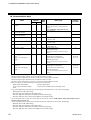
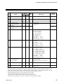
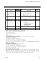
5. RKC COMMUNICATION PROTOCOL
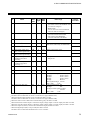
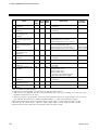
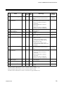
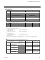
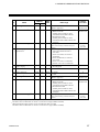
No.
Name
11 Event 2 set value
(EV2) 1, 2, 3, 4
(Event 2 set value (EV2)
[high])
RKC
No. of AttriIdenData range
digits bute
tifier
A2
6
R/W Deviation action:
−Input span to +Input span
Input value or set value action:
Same as input range
Factory
set value
TC/RTD:
50 (50.0)
V/I: 5.0
Varies with the setting of the Decimal point
position.
12 Heater break alarm 1
(HBA1) set value 5, 6
13 Heater break alarm 2
(HBA2) set value 5, 6
14 Control loop break alarm
(LBA) time 5, 7
15 LBA deadband (LBD) 5, 7
A3
6
R/W
0.0 to 100.0 A
0.0
A4
6
R/W
0.0 to 100.0 A
0.0
A5
6
R/W
0 to 7200 seconds (0: Unused)
480
A6
6
R/W
0 to Input span
0
Varies with the setting of the Decimal point
position.
16 Autotuning (AT)
G1
6
R/W
17 Unused
G2
6
R/W
18 Proportional band
[heat-side]
P1
6
R/W
0: PID control
1: AT start
Must be always “0”
TC/RTD inputs:
1 (0.1) to Input span (Unit: °C [°F])
Varies with the setting of the Decimal point
position.
0
TC/RTD:
30 (30.0)
V/I: 3.0
19 Integral time
I1
6
R/W
Voltage (V)/current (I) inputs:
0.1 to 100.0 % of Input span
0 (0.0): ON/OFF action
1 to 3600 seconds (0: PD action)
20 Derivative time
D1
6
R/W
1 to 3600 seconds (0: PI action)
60
21 Anti-reset windup (ARW)
W1
6
R/W
1 to 100 % of proportional band
[heat-side]
(0: Integral action is always OFF)
100
240
1
When the Digital output 2 (DO2) is not provided, this data is invalid.
The data is also invalid when “0: None” is set for Event 2 type (identifier: XB).
2
Data is invalid if any of the following Event functions are selected:
・Heater break alarm (HBA)
・Monitor during RUN
・Control loop break alarm (LBA)
・Output of the communication monitoring result
・FAIL
3
If any of the following Event functions are selected, this data will be Event 2 set value (EV2) [high].
・Band (High/Low individual setting)
・Deviation high/low (High/Low individual setting)
・Deviation high/low with hold action (High/Low individual setting)
・Deviation high/low with re-hold action (High/Low individual setting)
4
For the deviation action, input value action and set value action, refer to 8.2 Deviation Action, Input Value Action
and Set Value Action (P. 74).
5
Digital output (DO) must be provided.
6
Current transformer (CT) input must be provided and Heater break alarm (HBA) must be selected as an Event
function.
7
Control loop break alarm (LBA) must be selected as an Event function.
The data is invalid when the control action is Heat/Cool PID action with autotuning (AT).
IMR02C16-E3
29
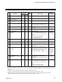
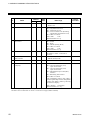
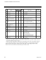
5. RKC COMMUNICATION PROTOCOL
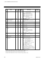
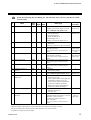
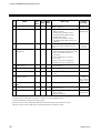
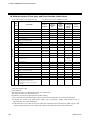
No.
Name
22 Proportional cycle time
[heat-side] 1
RKC
No. of AttriIdenData range
digits bute
tifier
T0
6
R/W 0 to 100 seconds
0: Setting below 1 second is possible
for Proportional cycle time [heatside] (identifier: TA).
23 Proportional band
[cool-side] 3
P2
6
R/W
24 Overlap/Deadband 3
V1
6
R/W
1 to 1000 % of proportional band
[heat-side]
(ON/OFF control of cool-side only is
not possible)
TC/RTD inputs:
−10 (−10.0) to +10 (+10.0) °C [°F]
Factory
set value
Relay contact
output: 20
Voltage pulse
output, triac
output, open
collector
output: 2
100
0 (0.0)
Varies with the setting of the Decimal point
position.
25 Proportional cycle time
[cool-side] 1, 2, 3
T1
6
26 PV bias
PB
6
Voltage (V)/current (I) inputs:
−10.0 to +10.0 % of Input span
R/W 0 to 100 seconds
0: Setting below 1 second is possible
for Proportional cycle time [coolside] (identifier: TB).
R/W
TC/RTD inputs:
−1999 (−199.9) to
+9999 (+999.9) °C [°F]
Voltage (V)/current (I) inputs:
−Input span to +Input span
Relay contact
output: 20
Voltage pulse
output, triac
output, open
collector
output: 2
0 (0.0)
Varies with the setting of the Decimal point
position.
27 Set lock level
LK
6
R/W
0:
1:
All parameter can be changed
Lock “Parameter Group” F01
through F10
2: Lock “Parameter Group” F02
through F10
3: Lock “Parameter Group” F03
through F10
4: Lock “Parameter Group” F04
through F10
5: Lock “Parameter Group” F05
through F10
6: Lock “Parameter Group” F06
through F10
7: Lock “Parameter Group” F07
through F10
8: Lock “Parameter Group” F08
through F10
9: Lock “Parameter Group” F09
through F10
10: Lock “Parameter Group” F10
0
1
When the heat-side control output is continuous output (voltage output or current output), this data is invalid.
When the cool-side control output is continuous output (voltage output or current output), this data is invalid.
3
When the control action is PID action with autotuning (AT), this data is invalid.
2
30
IMR02C16-E3
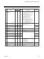
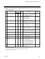
5. RKC COMMUNICATION PROTOCOL
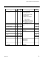
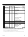
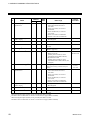
No.
Name
28 EEPROM mode
RKC
No. of AttriIdenData range
digits bute
tifier
EB
6
R/W 0: Backup mode
Factory
set value
0
(Set values stored to the EEPROM when
set values are changed.)
1: Buffer mode
(No set values stored to the EEPROM
when set values are changed.)
6
0: The content of the EEPROM does not
coincide with that of the RAM.
1: The content of the EEPROM
coincides with that of the RAM.
R/W To release the interlock, write “0 (zero).”
TD
6
R/W
0
32 Event 2 timer 2
TG
6
R/W
33 Manipulated output value
(MV1) monitor [heat-side]
34 Manipulated output value
(MV2) monitor [cool-side] 3
35 Manipulated output
ON/OFF state monitor
[heat-side] 4
36 Manipulated output
ON/OFF state monitor
[cool-side] 3, 5, 6
37 Model code
O1
6
RO
O2
6
RO
Q1
6
RO
Q2
6
RO
ID
32
RO
Model code (character)
38 ROM version monitor
VR
8
RO
ROM version
39 Comprehensive event state
AJ
6
RO
40 Digital input (DI) state 7
L1
6
RO
Least significant digit: Event 1 (EV1)
2nd digit:
Event 2 (EV2)
3rd digit:
Event 3 (EV3)
4th digit:
Event 4 (EV4)
5th digit:
Burnout
Most significant digit: Unused
Data 0: OFF
1: ON
Least significant digit: DI1
2nd digit:
DI2
3rd digit to Most significant digit:
Unused
Data 0: OFF
1: ON
29 EEPROM state
EM
6
30 Interlock release
IR
31 Event 1 timer 1
RO
0 to 600 seconds
Data can be written only in STOP mode.
0
0
Within output limiter range
0: Output OFF
1: Output ON
1
When the Digital output 1 (DO1) is not provided, this data is invalid.
The data is also invalid when “0: None” is set for Event 1 type (identifier: XA).
2
When the Digital output 2 (DO2) is not provided, this data is invalid.
The data is also invalid when “0: None” is set for Event 2 type (identifier: XB).
3
When the control action is PID action with autotuning (AT), this data is invalid.
4
When the heat-side control output is continuous output (voltage output or current output), this data is invalid.
5
When the cool-side control output is continuous output (voltage output or current output), this data is invalid.
6
When the Output 2 (OUT2) is used as the transmission output, this data is invalid.
7
When the Digital input (DI) is not provided, this data is invalid.
The data is also invalid when the DI function is set to “Unused”.
IMR02C16-E3
31
5. RKC COMMUNICATION PROTOCOL
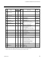
RKC
No. of AttriIdenData range
digits bute
tifier
41 Output state monitor
Q3
6
RO Least significant digit:
Output 1 (OUT1)
2nd digit: Output 2 (OUT2)
3rd digit: Digital output 1 (DO1)
4th digit: Digital output 2 (DO2)
5th digit: Digital output 3 (DO3)
Most significant digit:
Digital output 4 (DO4)
Data 0: OFF
1: ON
42 Set value (SV) display while MS
6
RO Setting limiter low to
the setting change rate
Setting limiter high
limiter is working
Varies with the setting of the Decimal point
No.
Name
Factory
set value
position.
43 Remaining time monitor
TR
6
RO
44 Event 3 state monitor 1
AC
6
RO
45 Event 4 state monitor 2
AD
6
46 Operation mode state
monitor
L0
6
47 Actual SV selection number
LZ
6
48 Auto (AUTO)/Manual
(MAN) transfer
49 Monitor selection
(no display)
J1
6
LP
6
00:00 to 99:59 (min : sec or hour : min)
0: Event 3 OFF
1: Event 3 ON
RO 0: Event 4 OFF
1: Event 4 ON
RO Least significant digit:
STOP
2nd digit: RUN
3rd digit: Manual (During RUN)
4th digit to Most significant digit:
Unused
Data 0: OFF
1: ON
RO 1 to 4
SV number in Timer 3 and Timer 4
functions.
R/W 0: Auto (AUTO) mode
1: Manual (MAN) mode
R/W 0 to 15 (Decimal)
Set the bit data in decimal.
Bit 0: Current transformer1 (CT1)
input value monitor
Bit 1: Current transformer 2 (CT2)
input value monitor
Bit 2: Manipulated output value (MV)
monitor a
Bit 3: Remaining time monitor
Bit 4 to Bit 7: Unused
Data 0: Display 1: No display
a
0
0
The manipulated output value (MV1)
monitor [heat-side] and the manipulated
output value (MV2) monitor [cool-side]
are both “No display.”
1
When the Digital output 3 (DO3) is not provided, this data is invalid.
The data is also invalid when “0: None” is set for Event 3 type (identifier: VC).
2
When the Digital output 4 (DO4) is not provided, this data is invalid.
The data is also invalid when “0: None” is set for Event 4 type (identifier: XD).
32
IMR02C16-E3
5. RKC COMMUNICATION PROTOCOL
No.
Name
50 Mode selection
(no display)
51 Set value 2 (SV2)
52 Set value 3 (SV3)
RKC
No. of AttriIdenData range
digits bute
tifier
LM
6
R/W 0 to 255 (Decimal)
Set the bit data in decimal.
Bit 0: Auto (AUTO)/Manual (MAN)
transfer a
Bit 1: Set data unlock/lock transfer a
Bit 2: Interlock release a
Bit 3: Disable <R/S key operation b
Bit 4 to Bit 6: Unused
Bit 7: Displays F21 and after c
a
Data 0: OFF (Display)
1: ON (No display)
b
Data 0: Enable <R/S key operation
1: Disable <R/S key operation
c
Data 0: No display F21 through F91.
1: Display F21 through F91.
S2
6
R/W Setting limiter low to
Setting limiter high
S3
6
R/W Varies with the setting of the Decimal point
Factory
set value
0
0
0
position.
53 Set value 4 (SV4)
S4
6
R/W
54 SV selection
ZB
6
R/W
55 F01 block selection
(no display)
56 Timer 1
DA
6
R/W
TH
57 Timer 2
0
1 to 4
1
6
0: Display
1: No display
R/W 00:01 to 99:59 (min : sec or hour : min)
00:01
TI
6
R/W
00:01
58 Timer 3
TJ
6
R/W
00:01
59 Timer 4
TK
6
R/W
00:01
60 Timer function
ZC
6
R/W
0
61 Repeat execution times
RR
6
0: Unused
1: Timer function 1
2: Timer function 2
3: Timer function 3
4: Timer function 4
R/W 0 to 9999 (9999: Infinite times)
62 F02 block selection
(no display)
DK
6
R/W
1
IMR02C16-E3
0: Display
1: No display
1
0
33
5. RKC COMMUNICATION PROTOCOL
No.
Name
63 Setting change rate limiter
(up)
64 Setting change rate limiter
(down)
65 F03 block selection
(no display)
66 Event 1 set value (EV1’)
[low] 1, 2
RKC
No. of AttriIdenData range
digits bute
tifier
HH
6
R/W 0 to Input span
(Unit: °C [°F]/unit time)
HL
6
R/W Varies with the setting of the Decimal point
Factory
set value
0 (0.0)
0 (0.0)
position.
DL
6
R/W
BT
6
R/W
0: Display
1: No display
−Input span to +Input span
Varies with the setting of the Decimal point
position.
67 Event 2 set value (EV2’)
[low] 2, 3
BU
6
R/W
68 Event 3 set value
(EV3) 4, 5, 6, 7
Event 3 set value (EV3)
[high]
A7
6
R/W
Deviation action:
−Input span to +Input span
Input value or set value action:
Same as input range
1
TC/RTD:
−50 (−50.0)
V/I: −5.0
TC/RTD:
−50 (−50.0)
V/I: −5.0
TC/RTD:
50 (50.0)
V/I: 5.0
Varies with the setting of the Decimal point
position.
69 Event 3 set value (EV3’)
[low] 2, 4
BV
6
R/W
−Input span to +Input span
Varies with the setting of the Decimal point
position.
TC/RTD:
−50 (−50.0)
V/I: −5.0
1
When the Digital output 1 (DO1) is not provided, this data is invalid.
The data is also invalid when “0: None” is set for Event 1 type (identifier: XA).
2
Data is valid if any of the following Event functions are selected:
・Band (High/Low individual setting)
・Deviation high/low (High/Low individual setting)
・Deviation high/low with hold action (High/Low individual setting)
・Deviation high/low with re-hold action (High/Low individual setting)
3
When the Digital output 2 (DO2) is not provided, this data is invalid.
The data is also invalid when “0: None” is set for Event 2 type (identifier: XB).
4
When the Digital output 3 (DO3) is not provided, this data is invalid.
The data is also invalid when “0: None” is set for Event 3 type (identifier: VC).
5
Data is invalid if any of the following Event functions are selected:
・Heater break alarm (HBA)
・Control loop break alarm (LBA)
・FAIL
・Monitor during RUN
・Output of the communication monitoring result
6
If any of the following event functions are selected, this data will be Event 3 set value (EV3) [high].
・Band (High/Low individual setting)
・Deviation high/low (High/Low individual setting)
・Deviation high/low with hold action (High/Low individual setting)
・Deviation high/low with re-hold action (High/Low individual setting)
7
For the deviation action, input value action and set value action, refer to 8.2 Deviation Action, Input Value Action
and Set Value Action (P. 74).
34
IMR02C16-E3
5. RKC COMMUNICATION PROTOCOL
No.
Name
70 Event 4 set value
(EV4) 1, 2, 3, 4
(Event 4 set value (EV4)
[high])
RKC
No. of AttriIdenData range
digits bute
tifier
A8
6
R/W Deviation action:
−Input span to +Input span
Input value or set value action:
Same as input range
Factory
set value
TC/RTD:
50 (50.0)
V/I: 5.0
Varies with the setting of the Decimal point
position.
71 Event 4 set value (EV4’)
[low] 1, 5
BW
6
R/W
72 F04 block selection
(no display) 6
73 Startup tuning (ST)
DM
6
R/W
ST
6
R/W
−Input span to +Input span
Varies with the setting of the Decimal point
position.
0: Display
1: No display
0: ST unused
1: Execute once *
2: Execute always
TC/RTD:
−50 (−50.0)
V/I: −5.0
0
0
* When the Startup tuning (ST) is finished,
the setting will automatically returns to
“0: ST unused.”
74 F05 block selection
(no display)
75 Fine tuning setting
DN
6
R/W
CB
6
R/W
0: Display
1: No display
−3 to +3
(0: Unused)
0
0
1
When the Digital output 4 (DO4) is not provided, this data is invalid.
The data is also invalid when “0: None” is set for Event 4 type (identifier: XD).
2
Data is invalid if any of the following Event functions are selected:
・Heater break alarm (HBA)
・Control loop break alarm (LBA)
・FAIL
・Monitor during RUN
・Output of the communication monitoring result
3
If any of the following Event functions are selected, this data will be Event 4 set value (EV4) [high].
・Band (High/Low individual setting)
・Deviation high/low (High/Low individual setting)
・Deviation high/low with hold action (High/Low individual setting)
・Deviation high/low with re-hold action (High/Low individual setting)
4
For the deviation action, input value action and set value action, refer to 8.2 Deviation Action, Input Value Action
and Set Value Action (P. 74).
5
Data is valid if any of the following Event functions are selected:
・Band (High/Low individual setting)
・Deviation high/low (High/Low individual setting)
・Deviation high/low with hold action (High/Low individual setting)
・Deviation high/low with re-hold action (High/Low individual setting)
6
Data is invalid in the following cases:
• When the Digital output (DO) is not provided
• When Event 1 type (identifier: XA), Event 2 type (identifier: XB), Event 3 type (identifier: VC), and Event 4 type
(identifier: XD) are all set to “0: None.”
• When Event 1 type (identifier: XA), Event 2 type (identifier: XB), Event 3 type (identifier: VC), and Event 4 type
(identifier: XD) are set to the Event functions “Heater break alarm (HBA),” “Control loop break alarm (LBA),”
“FAIL,” “Monitor during RUN,” and “Output of the communication monitoring result.”
IMR02C16-E3
35
5. RKC COMMUNICATION PROTOCOL
No.
Name
76 F06 block selection
(no display)
77 F07 block selection
(no display) 1
78 Minimum ON/OFF time of
proportioning cycle
[heat-side] 2
79 Output limiter high
[Heat-side output limiter
(high)]
80 Output limiter low
[Cool-side output limiter
(high)]
81 Minimum ON/OFF time of
proportioning cycle
[cool-side] 3, 4
82 F08 block selection
(no display)
83 PV digital filter
84 F09 block selection
(no display)
85 Manual manipulated output
value (MV)
86 F10 block selection
(no display)
87 Holding peak value ambient
temperature monitor
88 Integrated operating time
monitor
RKC
No. of AttriIdenData range
digits bute
tifier
DO
6
R/W 0: Display
1: No display
DQ
6
R/W 0: Display
1: No display
VI
6
R/W 0 to 1000 ms
OH
6
OL
6
R/W
PID control:
Output limiter low to 105.0 %
Heat/Cool PID control: 0.0 to 105.0 %
R/W PID control:
−5.0 % to Output limiter high
[Output limiter high > Output limiter low]
VJ
6
Heat/Cool PID control: 0.0 to 105.0 %
R/W 0 to 1000 ms
DR
6
R/W
F1
6
R/W
DS
6
R/W
ON
6
DT
6
HP
UT
Factory
set value
0
0
0
105.0
PID control:
−5.0
Heat/Cool PID
control: 105.0
0
0: Display
1: No display
0 to 100 seconds (0: Unused)
0
0
6
0: Display
1: No display
R/W PID control:
Output limiter low to
Output limiter high
Heat/Cool PID control:
−Cool-side output limiter (high) to
+Heat-side output limiter (high)
R/W 0: Display
1: No display
RO −10 to +100 °C (14 to 212 °F)
6
RO
0 to 9999 hours
1
0.0
1
1
Data is invalid in the following cases:
• When the Current transformer (CT) input is not provided, this data is invalid.
• When Event 1 type (identifier: XA), Event 2 type (identifier: XB), Event 3 type (identifier: VC), and Event 4 type
(identifier: XD) are all set to “0: None.”
• When any of Event 1 type (identifier: XA), Event 2 type (identifier: XB), Event 3 type (identifier: VC), or Event 4
type (identifier: XD) are not set to “Heater break alarm (HBA)” or “Control loop break alarm (LBA).”
2
When the heat-side control output is continuous output (voltage output or current output), this data is invalid.
3
When the cool-side control output is continuous output (voltage output or current output), this data is invalid.
4
When the control action is PID action with autotuning (AT), this data is invalid.
36
IMR02C16-E3
5. RKC COMMUNICATION PROTOCOL
Write the following data (excluding No. 102 and 103) after you have switched to STOP
(control stop).
No.
Name
89 Input type
90 Decimal point position
91 Burnout direction
92 Input scale high
RKC
No. of AttriIdenData range
digits bute
tifier
XI
6
R/W TC/RTD inputs: 0 to 31
Voltage (V)/current (I) inputs: 33 to 38
Refer to Input rang table (P. 42).
XU
6
R/W 0: No decimal place
1: One decimal place
2: Two decimal place
3: Three decimal places
TC/RTD inputs: 0 to 1
Voltage (V)/current (I) inputs: 0 to 3
BS
6
R/W 0: Upscale
1: Downscale
Valid only when the TC input is selected.
XV
6
R/W Input scale low to Maximum value of the
selected input range
Varies with the setting of the Decimal point
position.
93 Input scale low
XW
6
R/W
Minimum value of the selected input
range to Input scale high
Varies with the setting of the Decimal point
position.
94 Setting limiter high
SH
6
R/W
Setting limiter low to Input scale high
Factory
set value
Based on
model code
Based on
model code
0
Maximum
value of the
selected input
range
Minimum value
of the selected
input range
Input scale high
Varies with the setting of the Decimal point
position.
95 Setting limiter low
SL
6
R/W
Input scale low to Setting limiter high
Input scale low
Varies with the setting of the Decimal point
position.
96 PV flashing display at
input error
97 DI assignment 1
DU
6
H2
6
98 Output action at
STOP mode 2, 3
SS
6
99 Transmission output type 3
LB
6
100 Transmission output
scale high 3
CV
6
R/W
0: Flashing
1: Non-flashing display
R/W 0 to 7
Refer to DI assignment table (P. 43).
R/W 0: Both event output and transmission
output (AO) are off.
1: Event output remains unchanged, and
transmission output (AO) is off.
2: Event output is off, and transmission
output (AO) remains unchanged.
3: Both event output and transmission
output (AO) remain unchanged.
R/W 0: Manipulated output value (MV1)
1: Measured value (PV)
2: Set value (SV)
R/W When MV1 is selected:
Transmission output scale low to +105.0 %
When PV or SV is selected:
Transmission output scale low to
Input scale high
0
Based on
model code
0
1
High-limit
value of
input span
Varies with the setting of the Decimal point
position.
1
Digital input (DI) must be provided.
When the Digital output (DO) is not provided, the Event output action setting is invalid.
The Event output action setting is also invalid when there is no Event function.
3
Transmission output must be provided.
2
IMR02C16-E3
37
5. RKC COMMUNICATION PROTOCOL
No.
Name
101 Transmission output
scale low 1
RKC
No. of AttriIdenData range
digits bute
tifier
CW
6
R/W When MV1 is selected:
−5.0 % to Transmission output scale high
When PV or SV is selected:
Input scale low to
Transmission output scale high
Factory
set value
Low-limit
value of
input span
Varies with the setting of the Decimal point
position.
JK
6
R/W
−10.0 to +10.0 %
JL
6
R/W
−10.0 to +10.0 %
XA
6
R/W
105 Event 1 hold action 3
WA
6
106 Event 1 differential gap 3
HA
6
102 AO full scale
adjustment value 1, 2
103 AO zero
adjustment value 1, 2
104 Event 1 type 3
0 to 23
(Refer to page 44.)
R/W 0: OFF
1: Hold action ON
(When power turned on; when
transferred from STOP to RUN)
2: Re-hold action ON
(When power turned on; when
transferred from STOP to RUN; SV
changed)
R/W 0 to Input span
Varies with the setting of the Decimal point
position.
107 Event 1 output action at
input burnout 3
OA
6
108 Energized/De-energized of
Event 1 output 3
109 Event 1 interlock 3
Z1
6
LF
6
110 Event 2 type 4
XB
6
111 Event 2 hold action 4
WB
6
R/W
0: Event output is not forcibly turned ON
when the burnout function is activated.
1: ON at over-scale; no action at
underscale
2: ON at underscale; no action at
over-scale
3: ON at over-scale or underscale
4: OFF at over-scale or underscale
R/W 0: Energized
1: De-energized
R/W 0: Unused
1: Used
R/W 0 to 23
(Refer to page 44.)
R/W 0: OFF
1: Hold action ON
(When power turned on; when
transferred from STOP to RUN)
2: Re-hold action ON
(When power turned on; when
transferred from STOP to RUN; SV
changed)
Adjustment
value
Adjustment
value
Based on
model code
Based on
model code
TC/RTD:
2 (2.0)
V/I: 0.2
0
0
0
Based on
model code
Based on
model code
1
Transmission output must be provided.
This data can also be written in the RUN state.
3
When the Digital output 1 (DO1) is not provided, this data is invalid.
The data is also invalid when “0: None” is set for Event 1 type (identifier: XA).
4
When the Digital output 2 (DO2) is not provided, this data is invalid.
The data is also invalid when “0: None” is set for Event 2 type (identifier: XB).
2
38
IMR02C16-E3
5. RKC COMMUNICATION PROTOCOL
No.
Name
112 Event 2 differential gap 1
RKC
No. of AttriIdenData range
digits bute
tifier
HB
6
R/W 0 to Input span
Varies with the setting of the Decimal point
position.
113 Event 2 output action at
input burnout 1
OB
6
114 Energized/De-energized of
Event 2 output 1
115 Event 2 interlock 1
NB
6
LG
6
116 Event 3 type 2
VC
6
117 Event 3 hold action 2
WC
6
118 Event 3 differential gap 2
HC
6
R/W
0: Event output is not forcibly turned ON
when the burnout function is activated.
1: ON at over-scale; no action at
underscale
2: ON at underscale; no action at
over-scale
3: ON at over-scale or underscale
4: OFF at over-scale or underscale
R/W 0: Energized
1: De-energized
R/W 0: Unused
1: Used
R/W 0 to 23
(Refer to page 44.)
R/W
0: OFF
1: Hold action ON
(When power turned on; when
transferred from STOP to RUN)
2: Re-hold action ON
(When power turned on; when
transferred from STOP to RUN; SV
changed)
R/W 0 to Input span
Varies with the setting of the Decimal point
position.
119 Event 3 output action at
input burnout 2
OC
6
R/W
120 Energized/De-energized of
Event 3 output 2
121 Event 3 timer 2
NC
6
TE
6
0: Event output is not forcibly turned ON
when the burnout function is activated.
1: ON at over-scale; no action at
underscale
2: ON at underscale; no action at
over-scale
3: ON at over-scale or underscale
4: OFF at over-scale or underscale
R/W 0: Energized
1: De-energized
R/W 0 to 600 seconds
122 Event 3 interlock 2
LH
6
R/W
0: Unused
1: Used
Factory
set value
TC/RTD:
2 (2.0)
V/I: 0.2
0
0
0
Based on
model code
Based on
model code
TC/RTD:
2 (2.0)
V/I: 0.2
0
0
0
0
1
When the Digital output 2 (DO2) is not provided, this data is invalid.
The data is also invalid when “0: None” is set for Event 2 type (identifier: XB).
2
When the Digital output 3 (DO3) is not provided, this data is invalid.
The data is also invalid when “0: None” is set for Event 3 type (identifier: VC).
IMR02C16-E3
39
5. RKC COMMUNICATION PROTOCOL
No.
Name
123 Event 4 type 1
124 Event 4 hold action 1
125 Event 4 differential gap 1
RKC
No. of AttriIdenData range
digits bute
tifier
XD
6
R/W 0 to 23
(Refer to page 44.)
WD
6
R/W 0: OFF
1: Hold action ON
(When power turned on; when
transferred from STOP to RUN)
2: Re-hold action ON
(When power turned on; when
transferred from STOP to RUN; SV
changed)
HD
6
R/W 0 to Input span
Varies with the setting of the Decimal point
position.
R/W
Factory
set value
Based on
model code
Based on
model code
TC/RTD:
2 (2.0)
V/I: 0.2
0
126 Event 4 output action at
input burnout 1
OD
6
127 Energized/De-energized of
Event 4 output 1
128 Event 4 timer 1
ND
6
TF
6
0: Event output is not forcibly turned ON
when the burnout function is activated.
1: ON at over-scale; no action at
underscale
2: ON at underscale; no action at
over-scale
3: ON at over-scale or underscale
4: OFF at over-scale or underscale
R/W 0: Energized
1: De-energized
R/W 0 to 600 seconds
129 Event 4 interlock1
LI
6
R/W
0
130 CT ratio 2
(Number of turns)
XR
6
0: Unused
1: Used
R/W 1 to 1000
131 Number of HBA delay
times 2
132 Direct/Reverse action 3
EH
6
R/W
CTL-6-P-N:
800
CTL-12-S5610L-N: 1000
3
CA
6
R/W
133 Cool action 4
XQ
6
0 to 255 times
0: Direct action
1: Reverse action
R/W 0: Air cooling
1: Water cooling
2: Cooling gain linear
0
0
Based on
model code
Based on
model code
1
When the Digital output 4 (DO4) is not provided, this data is invalid.
The data is also invalid when “0: None” is set for Event 4 type (identifier: XD).
2
Current transformer (CT) input must be provided.
3
When the control action is Heat/Cool PID action with autotuning (AT), this data is invalid.
4
When the control action is PID action with autotuning (AT), this data is invalid.
40
IMR02C16-E3
5. RKC COMMUNICATION PROTOCOL
No.
Name
134 ON/OFF action
differential gap (upper)
RKC
No. of AttriIdenData range
digits bute
tifier
IV
6
R/W TC/RTD inputs:
0 (0.0) to 100 (100.0) °C [°F]
135 ON/OFF action
differential gap (lower)
IW
136 Control output at burnout
WH
Varies with the setting of the Decimal point
position.
6
R/W
6
Voltage (V)/Current (I) inputs:
0.0 to 10.0 % of Input span
R/W 0: Result of control computation
1: Low output limiter value
(Output OFF) *
Factory
set value
TC/RTD:
1 (1.0)
V/I: 0.1
TC/RTD:
1 (1.0)
V/I: 0.1
0
* On Heat/Cool PID control type, both
heating and cooling outputs are off.
137 Bumpless mode setting
OT
6
138 Derivative action
KA
6
139 AT cycles
G3
6
140 AT differential gap time
GH
141 ST start condition
6
0: Without bumpless
1: With bumpless
R/W 0: Measured value derivative
1: Deviation derivative
R/W 0: 1.5 cycles
1: 2.5 cycles
R/W 0 to 50 seconds
10
SU
6
R/W
0
142 Setting change rate limiter
unit time
143 Timer time unit
HU
6
RU
6
144 STOP display selection
DX
6
145 Time setting of proportional
cycle time [heat-side] 1, 3
146 Time setting of proportional
cycle time [cool-side] 2, 4, 5
TA
6
TB
6
1
R/W
0: Activate the ST function when the
power is turned on; when transferred
from STOP to RUN; or when the set
value (SV) is changed.
1: Activate the ST function when the
power is turned on; or when
transferred from STOP to RUN.
2: Activate the ST function when the set
value (SV) is changed.
R/W 0: Minute
1: Hours
R/W 0: Min. : sec.
1: Hour : min.
R/W 0: STOP on PV display + STOP lamp
(green) lights
1: STOP on SV display + STOP lamp
(green) lights
2: STOP lamp (green) lights
R/W 0: 0.1 seconds (fixed)
1: 0.25 seconds (fixed)
R/W 2: 0.5 seconds (fixed)
1
0
0
0
0
1
2
2
When the heat-side control output is continuous output (voltage output or current output), this data is invalid.
2
When the cool-side control output is continuous output (voltage output or current output), this data is invalid.
When Proportional cycle time [heat-side] (identifier: T0) is set to 0 seconds, this setting data becomes valid for the
Proportional cycle time [heat-side].
4
When the control action is PID action with autotuning (AT), this data is invalid.
5
When Proportional cycle time [cool-side] (identifier: T1) is set to 0 seconds, this setting data becomes valid for the
Proportional cycle time [cool-side].
3
IMR02C16-E3
41
5. RKC COMMUNICATION PROTOCOL
Input range table
Do not set to any number which is not described in the input type table. This may cause malfunctioning.
Set value
0
1
2
3
4
5
6
8
9
10
11
12
13
14
15
16
17
18
19
20
21
22
23
24
25
26
27
28
29
30
31
33
34
35
36
37
38
42
Input type
TC input
RTD input
TC input
RTD input
Voltage input
Current input
K
K
K
J
J
T
T
S
R
E
B
N
PLII
W5Re/W26Re
Pt100
JPt100
K
K
J
J
T
T
T
S
R
E
B
N
PLII
W5Re/W26Re
Pt100
0 to 1 V DC
0 to 5 V DC
0 to 10 V DC
1 to 5 V DC
0 to 20 mA DC
4 to 20 mA DC
−199.9 to +400.0 °C
0.0 to 800.0 °C
−200 to +1372 °C
−199.9 to +300.0 °C
−200 to +1200 °C
−199.9 to +300.0 °C
0.0 to 400.0 °C
0 to 1769 °C
0 to 1769 °C
0 to 1000 °C
0 to 1820 °C
0 to 1300 °C
0 to 1390 °C
0 to 2320 °C
−199.9 to +649.0 °C
−199.9 to +649.0 °C
−100.0 to +752.0 °F
−328 to +2501 °F
−199.9 to +555.0 °F
−328 to +2192 °F
−199.9 to +300.0 °F
0.0 to 600.0 °F
−328 to +752 °F
0 to 3216 °F
0 to 3216 °F
0 to 1832 °F
0 to 3308 °F
0 to 2372 °F
0 to 2534 °F
0 to 4208 °F
−199.9 to +900.0 °F
Programmable range
−1999 to +9999
[The decimal point position is selectable]
(Factory set value: 0.0 to 100.0)
IMR02C16-E3
5. RKC COMMUNICATION PROTOCOL
DI assignment
Set value
1
DI1
DI2
0
Unused (No DI assignment)
1
SV selection function (SV1 to SV4) 1
2
SV selection function (SV1 to SV2) 2
RUN/STOP transfer 3
3
SV selection function (SV1 to SV2) 2
AUTO/MAN transfer 4
4
SV selection function (SV1 to SV2) 2
Interlock release 5
5
RUN/STOP transfer 3
AUTO/MAN transfer 4
6
RUN/STOP transfer 3
Interlock release 5
7
AUTO/MAN transfer 4
Interlock release 5
SV selection function (SV1 to SV4)
SV1
SV2
SV3
SV4
DI1
Contact open
Contact closed
Contact open
Contact closed
DI2
Contact open
Contact open
Contact closed
Contact closed
(Data is determined in two seconds after DI1 and DI2 have changed.)
2
SV selection function (SV1 to SV2):
Contact open state: SV1
Contact closed state: SV2
3
RUN/STOP transfer:
Contact open state: STOP
Contact closed state: RUN
AUTO/MAN transfer:
Contact open state: MAN
Contact closed state: AUTO
4
5
Interlock release:
Interlock is released at the time of contact status change (from open to close) by edge monitoring.
Relation between key operations/communication and DI status
Mode select from key operation or
communication
DI switched *
Actual state
Indication lamp
Example:
In case of SV selection
function (SV1 to SV2)
SV1 is selected
SV2 is selected
(Contact closed)
Switched to SV2
SV1 lamp turns off
SV2 lamp lights
RUN
STOP lamp turns off
STOP
STOP lamp lights
AUTO mode
MAN lamp turns off
MAN mode
MAN lamp lights
SV selection
function
RUN/STOP
transfer
AUTO/MAN
transfer
RUN
STOP
AUTO mode
MAN mode
RUN (Contact closed)
STOP (Contact open)
RUN (Contact closed)
STOP (Contact open)
AUTO (Contact closed)
MAN (Contact open)
AUTO (Contact closed)
MAN (Contact open)
* Selected status by DI is not back up by EEPROM.
IMR02C16-E3
43
5. RKC COMMUNICATION PROTOCOL
Relation between Event types and Event function related items
9: Set values of Event function related items valid.
: Set values of Event function related items invalid.
Related items except event types
Event 1 type *
Set
value
Event type
Event 1
hold action *
Event 1
differential
gap *
Event 1
output
action at
input
burnout *
Energized/
De-energized
of Event 1
output *
Event 1
interlock *
0
None
1
Deviation high 1, 3
9
9
9
9
9
2
Deviation low 1, 3
9
9
9
9
9
3
Deviation high/low 1, 3
9
9
9
9
9
4
Band 1
9
9
9
9
9
5
Deviation high/low
[High/Low individual setting] 1, 3
9
9
9
9
9
6
Band [High/Low individual setting] 1
9
9
9
9
7
SV high 1
9
9
9
9
8
SV low 1
9
9
9
9
9
(Except re-hold)
9
9
9
9
9
(Except re-hold)
9
9
9
9
4
9
Process high
10
Process low 4
11
Control loop break alarm (LBA) 5
9
9
9
12
Monitor during RUN
9
9
9
13
FAIL (Fixed at de-energized: Contact open
when error occurs)
9
(always
de-energized)
9
14
Deviation high 2, 3
9
9
9
9
9
15
Deviation low 2, 3
9
9
9
9
9
16
Deviation high/low 2, 3
9
9
9
9
9
17
Band 2
9
9
9
9
9
18
Deviation high/low
[High/Low individual setting] 2, 3
9
9
9
9
9
19
Band [High/Low individual setting] 2
9
9
9
9
20
SV high 2
9
9
9
9
21
SV low 2
9
9
9
9
22
Heater break alarm (HBA)
9
9
9
23
Output of the communication monitoring result
(Event signal is turned on when
communication is not properly made for
10 seconds.)
9
9
9
*: The above table explains the relation in the case of Event 1, however, the relations in the case of Event 2 to Event 4 are the same.
1
Using SV monitor value
Using local SV
3
This alarm function can add the hold action or re-hold action.
4
This alarm function can add a hold action.
5
Precautions for Control loop break alarm (LBA) setting:
• The control loop break alarm (LBA) function cannot be activated when AT function is turned on.
• Normally the control loop break alarm (LBA) time of parameter setting mode should be set to
approximately twice the integral time.
• If the LBA time is too short or does not match the controlled object requirements, LBA may turn ON
or OFF at inappropriate time or remain OFF. Change the LBA time based on the malfunction.
2
44
IMR02C16-E3
6. MODBUS COMMUNICATION PROTOCOL
The master controls communication between master and slave. A typical message consists of a request
(query message) sent from the master followed by an answer (response message) from the slave. When
master begins data transmission, a set of data is sent to the slave in a fixed sequence. When it is received,
the slave decodes it, takes the necessary action, and returns data to the master.
6.1 Message Format
The message consists of four parts: slave address, function code, data, and error check code which are
always transmitted in the same sequence.
Slave address
Function code
Data
Error check CRC-16
Message format
Slave address
The slave address is a number from 1 to 99 manually set at the front key panel of the controller.
For details, refer to 4. SETTING (P. 9).
Although all connected slave units receive the query message sent from the master, only the slave with
the slave address coinciding with the query message will accept the message.
Function code
The function codes are the instructions set at the master and sent to the slave describing the action to be
executed. The function codes are included when the slave responds to the master.
For details, refer to 6.2 Function Code (P. 46).
Data
The data to execute the function specified by the function code is sent to the slave and corresponding
data returned to the master from the slave.
For details, refer to 6.6 Register Read and Write (P. 51), 6.7 Data Configuration (P. 54)
and 6.8 Modbus Communication Data List (P. 55).
Error check
An error checking code (CRC-16: Cyclic Redundancy Check) is used to detect an error in the signal
transmission.
For details, refer to 6.5 Calculating CRC-16 (P. 48).
IMR02C16-E2
45
6. MODBUS COMMUNICATION PROTOCOL
6.2 Function Code
Function code contents
Function code
(Hexadecimal)
Function
Contents
03H
Read holding registers
Measured value (PV), Event status and
Monitor, etc.
06H
Preset single register
Set value (SV), Event set value,
PID constants and PV bias, etc.
08H
Diagnostics (loopback test)
Loopback test
Message length of each function (Unit: byte)
Function code
(Hexadecimal)
Function
Query message
Response message
Min
Max
Min
Max
03H
Read holding registers
8
8
7
255
06H
Preset single register
8
8
8
8
08H
Diagnostics (loopback test)
8
8
8
8
6.3 Communication Mode
Signal transmission between the master and slaves is conducted in Remote Terminal Unit (RTU) mode.
Items
Contents
Data bit length
8-bit (Binary)
Start mark of message
Unused
End mark of message
Unused
Message length
Refer to 6.2 Function code
Data time interval
Less than 24-bit time *
Error check
CRC-16 (Cyclic Redundancy Check)
* When sending a command message from the master, set intervals of data configuring one message to
time shorter than the 24-bit time. If time intervals become time longer than the 24-bit time the relevant
slave assumes that message sending from the master is terminated and there is no response.
46
IMR02C16-E3
6. MODBUS COMMUNICATION PROTOCOL
6.4 Slave Responses
(1) Normal response
• In the response message of the Read Holding Registers, the slave returns the read out data and the
number of data items with the same slave address and function code as the query message.
• In the response message of the Preset Single Register, the slave returns the same message as the
query message.
• In the response message of the Diagnostics (Loopback test), the slave returns the same message as
the query message.
(2) Defective message response
• If the query message from the master is defective, except for transmission error, the slave returns the
error response message without any action.
Slave address
Function code
Error code
Error check CRC-16
Error response message
• If the self-diagnostic function of the slave detects an error, the slave will return an error response
message to all query messages.
• The function code of each error response message is obtained by adding 80H to the function code of
the query message.
Error code
Contents
1
Function code error (An unsupported function code was specified)
2
When the mismatched address is specified.
3
• When the specified number of data items in the query message exceeds the
maximum number of data items available
• When the data written exceeds the setting range
4
Self-diagnostic error response
(3) No response
The slave ignores the query message and does not respond when:
• The slave address in the query message does not coincide with any slave address settings.
• The CRC code of the master does not coincide with that of the slave.
• Transmission error such as overrun, framing, parity and etc., is found in the query message.
• Data time interval in the query message from the master exceeds 24-bit time.
IMR02C16-E3
47
6. MODBUS COMMUNICATION PROTOCOL
6.5 Calculating CRC-16
The Cyclic Redundancy Check (CRC) is a 2 byte (16-bit) error check code. After constructing the data
message, not including start, stop, or parity bit, the master calculates a CRC code and appends this to the
end of the message. The slave will calculate a CRC code from the received message, and compare it with
the CRC code from the master. If they do not coincide, a communication error has occurred and the slave
does not respond.
The CRC code is formed in the following sequence:
1. Load FFFFH to a 16-bit CRC register.
2. Exclusive OR (⊕) the first byte (8 bits) of the message with the CRC register. Return the result to the
CRC register.
3. Shift the CRC register 1 bit to the right.
4. If the carry flag is 1, exclusive OR the CRC register with A001 hexadecimal and return the result to
the CRC register. If the carry flag is 0, repeat step 3.
5. Repeat step 3 and 4 until there have been 8 shifts.
6. Exclusive OR the next byte (8 bits) of the message with the CRC register.
7. Repeat step 3 through 6 for all bytes of the message (except the CRC).
8. The CRC register contains the 2 byte CRC error code. When they are appended to the message, the
low-order byte is appended first, followed by the high-order byte.
48
IMR02C16-E3
6. MODBUS COMMUNICATION PROTOCOL
The flow chart of CRC-16
START
FFFFH
→ CRC Register
CRC Register ⊕ next byte of the message
→
CRC Register
0→n
Shift CRC Register right 1 bit
Carry flag is 1
No
Yes
CRC Register ⊕ A001H
→
CRC Register
n+1→n
No
n>7
Yes
No
Is message
complete?
Yes
Reverse with high-order byte and low-order byte of CRC register
END
The ⊕ symbol indicates an exclusive OR operation. The symbol for the number of data bits is n.
IMR02C16-E3
49
6. MODBUS COMMUNICATION PROTOCOL
Example of a CRC calculation in the ‘C’ language
This routine assumes that the data types ‘uint16’ and ‘uint8’ exists. Theses are unsigned 16-bit integer
(usually an ‘unsigned short int’ for most compiler types) and unsigned 8-bit integer (unsigned char).
‘z_p’ is a pointer to a Modbus message, and ‘z_messaage_length’ is its length, excluding the CRC. Note
that the Modbus message will probably contain NULL characters and so normal C string handling
techniques will not work.
uint16 calculate_crc(byte *z_p, unit16 z_message_length)
/* CRC runs cyclic Redundancy Check Algorithm on input z_p
/* Returns value of 16 bit CRC after completion and
/* always adds 2 crc bytes to message
/* returns 0 if incoming message has correct CRC
*/
*/
*/
*/
{
uint16 CRC= 0xffff;
uint16 next;
uint16 carry;
uint16 n;
uint8 crch, crcl;
while (z_messaage_length--) {
next = (uint16) *z_p;
CRC ^= next;
for (n = 0; n < 8; n++) {
carry = CRC & 1;
CRC >>= 1;
if (carry) {
CRC ^= 0xA001;
}
}
z_p++;
}
crch = CRC / 256;
crcl = CRC % 256
z_p [z_messaage_length++] = crcl;
z_p [z_messaage_length] = crch;
return CRC;
}
50
IMR02C16-E3
6. MODBUS COMMUNICATION PROTOCOL
6.6 Register Read and Write
6.6.1 Read holding registers [03H]
The query message specifies the starting register address and quantity of registers to be read.
The contents of the holding registers are entered in the response message as data, divided into two parts: the
high-order 8-bit and the low-order 8-bit, arranged in the order of the register numbers.
Example: The contents of the four holding registers from 0000H [Measured value (PV) monitor]
to 0003H [Event 1 state monitor] are the read out from slave address 2.
Query message
Slave address
Function code
02H
03H
Starting No.
High
Low
00H
00H
First holding register address
Quantity
High
Low
00H
04H
The setting must be between 1 (0001H) and
125 (007DH).
CRC-16
High
Low
44H
3AH
Normal response message
Slave address
02H
Function code
Number of data
03H
08H
First holding register contents
()
High
Low
00H
19H
Next holding register contents
(
High
Low
00H
00H
Next holding register contents
(
High
Low
00H
00H
Next holding register contents
(
High
Low
00H
00H
CRC-16
High
Low
12H
52H
Number of holding registers × 2
Error response message
Slave address
80H + Function code
02H
83H
03H
Error code
CRC-16
IMR02C16-E3
High
Low
F1H
31H
51
6. MODBUS COMMUNICATION PROTOCOL
6.6.2 Preset single register [06H]
The query message specifies data to be written into the designated holding register. The write data is
arranged in the query message with high-order 8-bit first and low-order 8-bit next. Only R/W holding
registers can be specified.
Example: Data is written into the holding register 0006H [Set value 1 (SV1)] of slave address 1.
Query message
Slave address
Function code
01H
06H
Holding register number
High
Low
00H
06H
Write data
High
Low
00H
32H
CRC-16
High
Low
E8H
1EH
Any data within the range
Normal response message
Slave address
Function code
01H
06H
Holding register number
High
Low
00H
06H
Write data
High
Low
00H
32H
CRC-16
High
Low
E8H
1EH
Contents will be the same as query message data.
Error response message
Slave address
80H + Function code
01H
86H
02H
Error code
CRC-16
52
High
Low
C3H
A1H
IMR02C16-E3
6. MODBUS COMMUNICATION PROTOCOL
6.6.3 Diagnostics (Loopback test) [08H]
The master’s query message will be returned as the response message from the slave.
This function checks the communication system between the master and slave (the controller).
Example: Loopback test for slave address 1
Query message
Slave address
Function code
01H
08H
Test code
High
Low
00H
00H
Test code must be set to 00.
Data
High
Low
1FH
34H
Any pertinent data
CRC-16
High
Low
E9H
ECH
Normal response message
Slave address
Function code
01H
08H
Test code
High
Low
00H
00H
Data
High
Low
1FH
34H
CRC-16
High
Low
E9H
ECH
Contents will be the same as query message data.
Error response message
Slave address
80H + Function code
01H
88H
03H
Error code
CRC-16
IMR02C16-E3
High
Low
06H
01H
53
6. MODBUS COMMUNICATION PROTOCOL
6.7 Caution for Handling Communication Data
• The numeric range of data used in Modbus protocol is 0000H to FFFFH. Only the set value within the
setting range is effective.
FFFFH represents −1.
• The Modbus protocol does not recognize data with decimal points during communication.
Example: When Manipulated output value (MV1) monitor [heat-side] is 5.0 %,
5.0 is processed as 50,
50 = 0032H
Manipulated output value (MV1)
monitor [heat-side]
High
Low
00H
32H
• If data (holding register) exceeding the accessible address range is accessed, an error response
message is returned.
• Read data of unused item is a default value.
• Any attempt to write to an unused item is not processed as an error. Data cannot be written into an
unused item.
• An attribute of the item for functions which are not in the controller is RO (read only). If read action
to this item is performed, the read data will be “0.” If write action to this item is performed, no error
message is indicated and no data is written.
• Commands should be sent at time intervals of 24 bits after the master receives the response message.
54
IMR02C16-E3
6. MODBUS COMMUNICATION PROTOCOL
6.8 Modbus Communication Data List
Reference to communication data list
(1)
No.
(2)
(3)
Register
address
HEX
DEC
0000
0
Name
1 Measured value (PV)
monitor
(4)
Attribute
RO
Data range
(5)
Factory
set value
Within input range
Varies with the setting of the Decimal point
position.
Refer to Input range table (P. 42).
2 Current transformer 1 (CT1)
input value monitor 1
3 Current transformer 2 (CT2)
input value monitor 1
(1) Name:
0001
1
RO
0002
2
RO
0.0 to 100.0 A
Communication data name
(2) Register address: Modbus communication data register addresses
HEX: Hexadecimal
DEC: Decimal
(3) Attribute:
A method of how communication data items are read or written when viewed from
the host computer is described.
RO:
Only reading data is possible.
Data direction
Host computer
Controller
R/W: Reading and writing data is possible.
Data direction
Host computer
(4) Data range:
Controller
Read or write range of communication data
Bit data
16-bit data
Bit 15 …………….…………………… Bit 0
(5) Factory set value: Factory set value of communication data
For details of data, refer to the RB series Instruction Manual (IMR02C15-E).
For data corresponding to No. 85 to 144 (other than No. 98 AO full scale adjustment value
and No. 99 AO zero adjustment value), its attribute becomes RO (Only reading data is
possible) during RUN (control).
When setting data corresponding to No. 85 to 144 (other than No. 98 and No. 99), write the
data after STOP (control stop) is selected.
IMR02C16-E3
55
6. MODBUS COMMUNICATION PROTOCOL
Communication data
No.
Name
1 Measured value (PV)
monitor
Register
address
HEX
DEC
0000
0
Attribute
RO
Data range
Within input range
Factory
set value
Varies with the setting of the Decimal point
position.
2 Current transformer 1 (CT1)
input value monitor 1
3 Current transformer 2 (CT2)
input value monitor 1
4 Event 1 state monitor 2
0001
1
RO
0002
2
RO
0003
3
RO
5 Event 2 state monitor 3
0004
4
RO
6 Burnout state monitor
0005
5
RO
7 Set value 1 (SV1)
0006
6
R/W
Refer to Input range table (P. 42).
0.0 to 100.0 A
0: Event 1 OFF
1: Event 1 ON
0: Event 2 OFF
1: Event 2 ON
0: OFF
1: ON (burnout)
Setting limiter low to
Setting limiter high
0
Varies with the setting of the Decimal point
position.
8 Event 1 set value
(EV1) 2, 4, 5, 6
Event 1 set value (EV1)
[high]
0007
7
R/W
Deviation action:
−Input span to +Input span
Input value or set value action:
Same as input range
TC/RTD:
50 (50.0)
V/I: 5.0
Varies with the setting of the Decimal point
position.
9 Event 2 set value
(EV2) 3, 4, 6, 7
Event 2 set value (EV2)
[high]
0008
8
R/W
Deviation action:
−Input span to +Input span
Input value or set value action:
Same as input range
TC/RTD:
50 (50.0)
V/I: 5.0
Varies with the setting of the Decimal point
position.
1
Current transformer (CT) input must be provided.
When the Digital output 1 (DO1) is not provided, this data is invalid.
The data is also invalid when “0: None” is set for Event 1 type (address: 0070H).
3
When the Digital output 2 (DO2) is not provided, this data is invalid.
The data is also invalid when “0: None” is set for Event 2 type (address: 0077H).
4
Data is invalid if any of the following Event functions are selected:
・Heater break alarm (HBA)
・Monitor during RUN
・Control loop break alarm (LBA)
・Output of the communication monitoring result
・FAIL
5
If any of the following Event functions are selected, this data will be Event 1 set value (EV1) [high].
・Band (High/Low individual setting)
・Deviation high/low (High/Low individual setting)
・Deviation high/low with hold action (High/Low individual setting)
・Deviation high/low with re-hold action (High/Low individual setting)
6
For the deviation action, input value action and set value action, refer to 8.2 Deviation Action, Input Value Action
and Set Value Action (P. 74).
7
If any of the following Event functions are selected, this data will be Event 2 set value (EV2) [high].
・Band (High/Low individual setting)
・Deviation high/low (High/Low individual setting)
・Deviation high/low with hold action (High/Low individual setting)
・Deviation high/low with re-hold action (High/Low individual setting)
2
56
IMR02C16-E3
6. MODBUS COMMUNICATION PROTOCOL
No.
Name
10 Heater break alarm 1
(HBA1) set value 1, 2
11 Heater break alarm 2
(HBA2) set value 1, 2
12 Control loop break alarm
(LBA) time 1, 3
13 LBA deadband (LBD) 1, 3
Register
address
HEX
DEC
0009
9
Attribute
Data range
Factory
set value
R/W
0.0 to 100.0 A
0.0
000A
10
R/W
0.0 to 100.0 A
0.0
000B
11
R/W
0 to 7200 seconds (0: Unused)
480
000C
12
R/W
0 to Input span
0
Varies with the setting of the Decimal point
position.
14 Autotuning (AT)
000D
13
R/W
15 Unused
000E
14
16 Proportional band
[heat-side]
000F
15
R/W
0: PID control
1: AT start
0
TC/RTD inputs:
1 (0.1) to Input span (Unit: °C [°F])
Varies with the setting of the Decimal point
position.
TC/RTD:
30 (30.0)
V/I: 3.0
17 Integral time
0010
16
R/W
Voltage (V)/current (I) inputs:
0.1 to 100.0 % of Input span
0 (0.0): ON/OFF action
1 to 3600 seconds (0: PD action)
18 Derivative time
0011
17
R/W
1 to 3600 seconds (0: PI action)
60
19 Anti-reset windup (ARW)
0012
18
R/W
100
20 Proportional cycle time
[heat-side] 4
0013
19
R/W
1 to 100 % of proportional band
[heat-side]
(0: Integral action is always OFF)
0 to 100 seconds
0: Setting below 1 second is possible
for Proportional cycle time
[heat-side] (address: 009BH).
21 Proportional band
[cool-side] 5
0014
20
R/W
22 Overlap/Deadband 5
0015
21
R/W
01 to 1000 % of proportional band
[heat- side]
(ON/OFF control of cool-side only is not
possible)
TC/RTD inputs:
−10 (−10.0) to +10 (+10.0) °C [°F]
240
Relay contact
output: 20
Voltage pulse
output, triac
output, open
collector
output: 2
100
0 (0.0)
Varies with the setting of the Decimal point
position.
Voltage (V)/current (I) inputs:
−10.0 to +10.0 % of Input span
1
Digital output (DO) must be provided.
Current transformer (CT) input must be provided and Heater break alarm (HBA) must be selected as an Event
function.
3
Control loop break alarm (LBA) must be selected as an Event function.
The data is invalid when the control action is Heat/Cool PID action with autotuning (AT).
4
When the heat-side control output is continuous output (voltage output or current output), this data is invalid.
5
When the control action is PID action with autotuning (AT), this data is invalid.
2
IMR02C16-E3
57
6. MODBUS COMMUNICATION PROTOCOL
No.
Name
23 Proportional cycle time
[cool-side] 1, 2
24 PV bias
Register
address
HEX
DEC
0016
22
0017
23
Attribute
Data range
R/W
0 to 100 seconds
0: Setting below 1 second is possible
for Proportional cycle time [coolside] (address: 009CH).
R/W
TC/RTD inputs:
−1999 (−199.9) to +9999 (+999.9) °C [°F]
Voltage (V)/current (I) inputs:
− Input span to + Input span
Factory
set value
Relay contact
output: 20
Voltage pulse
output, triac
output, open
collector
output: 2
0 (0.0)
Varies with the setting of the Decimal point
position.
1
2
58
25 Set lock level
0018
24
R/W
26 RUN/STOP transfer
0019
25
R/W
27 Unused
001A
26
28 EEPROM mode
001B
27
R/W
29 EEPROM state
001C
28
RO
30 Manipulated output value
(MV1) monitor [heat-side]
001D
29
RO
0
0:
1:
All parameter can be changed
Lock “Parameter Group” F01
through F10
2: Lock “Parameter Group” F02
through F10
3: Lock “Parameter Group” F03
through F10
4: Lock “Parameter Group” F04
through F10
5: Lock “Parameter Group” F05
through F10
6: Lock “Parameter Group” F06
through F10
7: Lock “Parameter Group” F07
through F10
8: Lock “Parameter Group” F08
through F10
9: Lock “Parameter Group” F09
through F10
10: Lock “Parameter Group” F10
0: RUN
1: STOP
0
0
0: Backup mode
(Set values stored to the EEPROM
when set values are changed.)
1: Buffer mode
(No set values stored to the EEPROM
when set values are changed.)
0: The content of the EEPROM does not
coincide with that of the RAM.
1: The content of the EEPROM
coincides with that of the RAM.
Within output limiter range
When the cool-side control output is continuous output (voltage output or current output), this data is invalid.
When the control action is PID action with autotuning (AT), this data is invalid.
IMR02C16-E3
6. MODBUS COMMUNICATION PROTOCOL
No.
Name
31 Manipulated output value
(MV2) monitor [cool-side] 1
32 Unused
Register
address
HEX
DEC
001E
30
Attribute
RO
Data range
Factory
set value
Within output limiter range
001F
·
·
·
002C
002D
31
·
·
·
44
45
RO
002E
46
RO
002F
47
RO
36 Digital input (DI) state 5
0030
48
RO
37 Output state monitor
0031
49
RO
38 Set value (SV) display while
the setting change rate
limiter is working
0032
50
RO
39 Remaining time monitor
0033
51
RO
0 to 5999 (sec or min)
40 Event 3 state monitor 6
0034
52
RO
0: Event 3 OFF
1: Event 3 ON
33 Manipulated output
ON/OFF state monitor
[heat-side] 2
34 Manipulated output
ON/OFF state monitor
[cool-side] 1, 3, 4
35 Comprehensive event state
0: Output OFF
1: Output ON
Bit data
Bit 0: Event 1 (EV1)
Bit 1: Event 2 (EV2)
Bit 2: Event 3 (EV3)
Bit 3: Event 4 (EV4)
Bit 4: Burnout
Bit 5 to Bit 15: Unused
Data 0: OFF
1: ON
[Decimal number: 0 to 31]
Bit data
Bit 0: DI1
Bit 1: DI2
Bit 2 to Bit 15: Unused
Data 0: OFF
1: ON
[Decimal number: 0 to 3]
Bit data
Bit 0: Output 1 (OUT1)
Bit 1: Output 2 (OUT2)
Bit 2: Digital output 1 (DO1)
Bit 3: Digital output 2 (DO2)
Bit 4: Digital output 3 (DO3)
Bit 5: Digital output 4 (DO4)
Bit 6 to Bit 15: Unused
Data 0: OFF
1: ON
[Decimal number: 0 to 63]
Setting limiter low to
Setting limiter high
Varies with the setting of the Decimal point
position.
1
When the control action is PID action with autotuning (AT), this data is invalid.
When the heat-side control output is continuous output (voltage output or current output), this data is invalid.
3
When the cool-side control output is continuous output (voltage output or current output), this data is invalid.
4
When the Output 2 (OUT2) is used as the transmission output, this data is invalid.
5
When the Digital input (DI) is not provided, this data is invalid.
The data is also invalid when the DI function is set to “Unused.”
6
When the Digital output 3 (DO3) is not provided, this data is invalid.
The data is also invalid when “0: None” is set for Event 3 type (address: 007EH).
2
IMR02C16-E3
59
6. MODBUS COMMUNICATION PROTOCOL
41 Event 4 state monitor *
Register
address
HEX
DEC
0035
53
42 Error code
0036
54
43 Operation mode
state monitor
0037
55
44 Actual SV selection number
0038
56
45 Auto (AUTO)/Manual
(MAN) transfer
46 Interlock release
0039
57
003A
003B
No.
Name
47 Monitor selection
(no display)
Attribute
Data range
Factory
set value
58
0: Event 4 OFF
1: Event 4 ON
RO Bit data
Bit 0: Adjustment data error
Bit 1: Data back-up error
Bit 2: A/D conversion error (Including
temperature compensation error)
Bit 3 to Bit 15: Unused
Data 0: OFF
1: ON
[Decimal number: 0 to 7]
RO Bit data
Bit 0: STOP
Bit 1: RUN
Bit 2: Manual (During RUN)
Bit 3 to Bit 15: Unused
Data 0: OFF
1: ON
[Decimal number: 0 to 7]
RO 1 to 4
SV number in Timer 3 and Timer 4
functions.
R/W 0: Auto (AUTO) mode
1: Manual (MAN) mode
R/W To release the interlock, write “0 (zero).”
59
R/W
0
RO
Bit data
Bit 0: Current transformer1 (CT1)
input value monitor
Bit 1: Current transformer2 (CT2)
input value monitor
Bit 2: Manipulated output value (MV)
monitor a
Bit 3: Remaining time monitor
Bit 4 to Bit 15: Unused
a
0
0
The manipulated output value (MV1)
monitor [heat-side] and the manipulated
output value (MV2) monitor [cool-side]
are both “No display.”
Data 0: Display 1: No display
[Decimal number: 0 to 15]
* When the Digital output 4 (DO4) is not provided, this data is invalid.
The data is also invalid when “0: None” is set for Event 4 type (address: 0085H).
60
IMR02C16-E3
6. MODBUS COMMUNICATION PROTOCOL
No.
Name
48 Mode selection
(no display)
Register
address
HEX
DEC
003C
60
Attribute
R/W
Data range
Bit data
Bit 0: Auto (AUTO)/Manual (MAN)
transfer a
Bit 1: Set data unlock/lock transfer a
Bit 2: Interlock release a
Bit 3: Disable <R/S key operation b
Bit 4 to Bit 6: Unused
Bit 7: Displays F21 and after c
Bit 8 to Bit 15: Unused
a
Data 0: Display 1: No display
b
Data 0: Enable <R/S key operation
1: Disable <R/S key
c
Data 0: No display F21 through F91.
1: Display F21 through F91.
[Decimal number: 0 to 255]
Setting limiter low to
Setting limiter high
Factory
set value
0
49 Set value 2 (SV2)
003D
61
R/W
50 Set value 3 (SV3)
003E
62
R/W
51 Set value 4 (SV4)
003F
63
R/W
52 SV selection
0040
64
R/W
1 to 4
1
53 F01 block selection
(no display)
54 Timer 1
0041
65
R/W
1
0042
66
R/W
0: Display
1: No display
1 to 5999 (second or minute)
55 Timer 2
0043
67
R/W
1
56 Timer 3
0044
68
R/W
1
57 Timer 4
0045
69
R/W
1
58 Timer function
0046
70
R/W
59 Repeat execution times
0047
71
R/W
60 F02 block selection
(no display)
0048
72
R/W
IMR02C16-E3
Varies with the setting of the Decimal point
position.
0
0
0
1
0: Unused
1: Timer function 1
2: Timer function 2
3: Timer function 3
4: Timer function 4
0 to 9999 (9999: Infinite times)
0
0: Display
1: No display
1
0
61
6. MODBUS COMMUNICATION PROTOCOL
No.
Name
61 Setting change rate limiter
(up)
62 Setting change rate limiter
(down)
63 F03 block selection
(no display)
64 Event 1 set value (EV1’)
[low] 1, 2
Register
address
HEX
DEC
0049
73
Attribute
Data range
Factory
set value
R/W
0 to Input span
(Unit:°C [°F]/unit time)
0 (0.0)
0 (0.0)
004A
74
R/W
Varies with the setting of the Decimal point
position.
004B
75
R/W
004C
76
R/W
0: Display
1: No display
−Input span to +Input span
Varies with the setting of the Decimal point
position.
65 Event 2 set value (EV2’)
[low] 2, 3
004D
77
R/W
66 Event 3 set value
(EV3) 4, 5, 6, 7
(Event 3 set value (EV3)
[high])
004E
78
R/W
Deviation action:
−Input span to +Input span
Input value or set value action:
Same as input range
1
TC/RTD:
−50 (−50.0)
V/I: −5.0
TC/RTD:
−50 (−50.0)
V/I: −5.0
TC/RTD:
50 (50.0)
V/I: 5.0
Varies with the setting of the Decimal point
position.
67 Event 3 set value (EV3’)
[low] 2, 4
004F
79
R/W
−Input span to +Input span
Varies with the setting of the Decimal point
position.
TC/RTD:
−50 (−50.0)
V/I: −5.0
1
When the Digital output 1 (DO1) is not provided, this data is invalid.
The data is also invalid when “0: None” is set for Event 1 type (address: 0070H).
2
Data is valid if any of the following Event functions are selected:
・Band (High/Low individual setting)
・Deviation high/low (High/Low individual setting)
・Deviation high/low with hold action (High/Low individual setting)
・Deviation high/low with re-hold action (High/Low individual setting)
3
When the Digital output 2 (DO2) is not provided, this data is invalid.
The data is also invalid when “0: None” is set for Event 2 type (address: 0077H).
4
When the Digital output 3 (DO3) is not provided, this data is invalid.
The data is also invalid when “0: None” is set for Event 3 type (address: 007EH).
5
Data is invalid if any of the following Event functions are selected:
・Heater break alarm (HBA)
・Control loop break alarm (LBA)
・FAIL
・Monitor during RUN
・Output of the communication monitoring result
6
If any of the following Event functions are selected, this data will be Event 3 set value (EV3) [high].
・Band (High/Low individual setting)
・Deviation high/low (High/Low individual setting)
・Deviation high/low with hold action (High/Low individual setting)
・Deviation high/low with re-hold action (High/Low individual setting)
7
For the deviation action, input value action and set value action, refer to 8.2 Deviation Action, Input Value Action
and Set Value Action (P. 74).
62
IMR02C16-E3
6. MODBUS COMMUNICATION PROTOCOL
No.
Name
68 Event 4 set value
(EV4) 1, 2, 3, 4
(Event 4 set value (EV4)
[high])
Register
address
HEX
DEC
0050
80
Attribute
R/W
Data range
Deviation action:
−Input span to +Input span
Input value or set value action:
Same as input range
Factory
set value
TC/RTD:
50 (50.0)
V/I: 5.0
Varies with the setting of the Decimal point
position.
69 Event 4 set value (EV4’)
[low] 1, 5
0051
70 F04 block selection
(no display) 6
71 Startup tuning (ST)
0052
82
R/W
0053
83
R/W
0054
84
R/W
0055
85
R/W
72 F05 block selection
(no display)
73 Fine tuning setting
81
R/W
−Input span to +Input span
Varies with the setting of the Decimal point
position.
0:
1:
0:
1:
2:
Display
No display
ST unused
Execute once *
Execute always
* When the Startup tuning (ST) is
finished, the setting will
automatically returns to
“0: ST unused.”
0: Display
1: No display
−3 to +3
(0: Unused)
TC/RTD:
−50 (−50.0)
V/I: −5.0
0
0
0
0
1
When the Digital output 3 (DO3) is not provided, this data is invalid.
The data is also invalid when “0: None” is set for Event 4 type (address: 0085H).
2
Data is invalid if any of the following Event functions are selected:
・Heater break alarm (HBA)
・Control loop break alarm (LBA)
・FAIL
・Monitor during RUN
・Output of the communication monitoring result
3
If any of the following Event functions are selected, this data will be Event 4 set value (EV4) [high].
・Band (High/Low individual setting)
・Deviation high/low (High/Low individual setting)
・Deviation high/low with hold action (High/Low individual setting)
・Deviation high/low with re-hold action (High/Low individual setting)
4
For the deviation action, input value action and set value action, refer to 8.2 Deviation Action, Input Value Action
and Set Value Action (P. 74).
5
Data is valid if any of the following Event functions are selected:
・Band (High/Low individual setting)
・Deviation high/low (High/Low individual setting)
・Deviation high/low with hold action (High/Low individual setting)
・Deviation high/low with re-hold action (High/Low individual setting)
6
Data is invalid in the following cases:
• When the Digital output (DO) is not provided.
• When Event 1 type (address: 0070H), Event 2 type (address: 0077H), Event 3 type (address: 007EH), and Event 4
type (address: 0085H) are all set to “0: None.”
• When Event 1 type (address: 0070H), Event 2 type (address: 0077H), Event 3 type (address: 007EH), and Event 4
type (address: 0085H) are set to the Event functions “Heater break alarm (HBA),” “Control loop break alarm
(LBA),” “FAIL,” “Monitor during RUN,” and “Output of the communication monitoring result.”
IMR02C16-E3
63
6. MODBUS COMMUNICATION PROTOCOL
No.
Name
74 F06 block selection
(no display)
75 F07 block selection
(no display) 1
76 Minimum ON/OFF time of
proportioning cycle
[heat-side] 2
77 Output limiter high
[Heat-side output limiter
(high)]
78 Output limiter low
[Cool-side output limiter
(high)]
Register
address
HEX
DEC
0056
86
Attribute
R/W
0057
87
R/W
0058
88
R/W
0059
89
R/W
005A
90
R/W
0: Display
1: No display
0: Display
1: No display
0 to 1000 ms
PID control:
Output limiter low to 105.0 %
Heat/Cool PID control: 0.0 to 105.0 %
PID control:
−5.0 % to Output limiter high
[Output limiter high > Output limiter low]
005B
91
R/W
005C
92
R/W
005D
93
R/W
82 F09 block selection
(no display)
83 Manual manipulated output
value (MV)
005E
94
R/W
005F
95
R/W
84 F10 block selection
(no display)
0060
96
R/W
79 Minimum ON/OFF time of
proportioning cycle
[cool-side] 3, 4
80 F08 block selection
(no display)
81 PV digital filter
Data range
Heat/Cool PID control: 0.0 to 105.0 %
0 to 1000 ms
Factory
set value
0
0
0
105.0
PID control:
−5.0
Heat/Cool PID
control: 105.0
0
0: Display
1: No display
0 to 100 seconds (0: Unused)
0
0: Display
1: No display
PID control:
Output limiter low to
Output limiter high
Heat/Cool PID control:
− Cool-side output limiter (high) to
+ Heat-side output limiter (high)
0: Display
1: No display
0
1
0.0
1
1
Data is invalid in the following cases:
• When the Current transformer (CT) input is not provided, this data is invalid.
• When Event 1 type (address: 0070H), Event 2 type (address: 0077H), Event 3 type (address: 007EH), and Event 4
type (address: 0085H) are all set to “0: None.”
• When any of Event 1 type (address: 0070H), Event 2 type (address: 0077H), Event 3 type (address: 007EH), or
Event 4 type (address: 0085H) are not set to “Heater break alarm (HBA)” or “Control loop break alarm (LBA).”
2
When the heat-side control output is continuous output (voltage output or current output), this data is invalid.
3
When the cool-side control output is continuous output (voltage output or current output), this data is invalid.
4
When the control action is PID action with autotuning (AT), this data is invalid.
64
IMR02C16-E3
6. MODBUS COMMUNICATION PROTOCOL
Write the following data (excluding No. 102 and 103) after you have switched to STOP
(control stop).
85 Input type
Register
address
HEX
DEC
0061
97
86 Decimal point position
0062
98
R/W
87 Burnout direction
0063
99
R/W
88 Input scale high
0064
100
R/W
No.
Name
Attribute
R/W
Data range
TC/RTD inputs: 0 to 31
Voltage (V)/current (I) inputs: 33 to 38
Refer to Input rang table (P. 42).
0: No decimal place
1: One decimal place
2: Two decimal place
3: Three decimal places
TC/RTD inputs: 0 to 1
Voltage (V)/current (I) inputs: 0 to 3
0: Upscale
1: Downscale
Valid only when the TC input is selected.
Input scale low to Maximum value of the
selected input range
Varies with the setting of the Decimal point
position.
89 Input scale low
0065
101
R/W
Minimum value of the selected input
range to Input scale high
Varies with the setting of the Decimal point
position.
90 Setting limiter high
0066
102
R/W
Setting limiter low to Input scale high
Factory
set value
Based on
model code
Based on
model code
0
Maximum
value of the
selected input
range
Minimum value
of the selected
input range
Input scale high
Varies with the setting of the Decimal point
position.
91 Setting limiter low
0067
103
R/W
Input scale low to Setting limiter high
Input scale low
Varies with the setting of the Decimal point
position.
92 PV flashing display at
input error
93 DI assignment 1
0068
104
R/W
0069
105
R/W
94 Output action at
STOP mode 2, 3
006A
106
R/W
95 Transmission output type 3
006B
107
R/W
0: Flashing
1: Non-flashing display
0 to 7
Refer to DI assignment table (P. 43).
0: Both event output and transmission
output (AO) are off.
1: Event output remains unchanged, and
transmission output (AO) is off.
2: Event output is off, and transmission
output (AO) remains unchanged.
3: Both event output and transmission
output (AO) remain unchanged.
0: Manipulated output value (MV1)
1: Measured value (PV)
2: Set value (SV)
0
Based on
model code
0
1
1
Digital input (DI) must be provided.
When the Digital output (DO) is not provided, the Event output action setting is invalid.
The Event output action setting is also invalid when there is no Event function.
3
Transmission output must be provided.
2
IMR02C16-E3
65
6. MODBUS COMMUNICATION PROTOCOL
No.
Name
96 Transmission output
scale high 1
Register
address
HEX
DEC
006C
108
Attribute
R/W
Data range
When MV1 is selected:
Transmission output scale low to +105.0 %
When PV or SV is selected:
Transmission output scale low to
Input scale high
Factory
set value
High-limit
value of
input span
Varies with the setting of the Decimal point
position.
97 Transmission output
scale low 1
006D
109
R/W
When MV1 is selected:
−5.0 % to Transmission output scale high
When PV or SV is selected:
Input scale low to
Transmission output scale high
Low-limit
value of
input span
Varies with the setting of the Decimal point
position.
98 AO full scale
adjustment value1, 2
99 AO zero
adjustment value1, 2
100 Event 1 type 3
006E
110
R/W
−10.0 to +10.0 %
006F
111
R/W
−10.0 to +10.0 %
0070
112
R/W
101 Event 1 hold action 3
0071
113
R/W
102 Event 1 differential gap 3
0072
114
R/W
0 to 23
(Refer to page 44.)
0: OFF
1: Hold action ON
(When power turned on;
when transferred from STOP to RUN)
2: Re-hold action ON
(When power turned on; when
transferred from STOP to RUN;
SV changed)
0 to Input span
Varies with the setting of the Decimal point
position.
103 Event 1 output action at
input burnout 3
0073
115
R/W
104 Energized/De-energized of
Event 1 output 3
105 Event 1 timer 3
0074
116
R/W
0075
117
R/W
106 Event 1 interlock 3
0076
118
R/W
0: Event output is not forcibly turned ON
when the burnout function is
activated.
1: ON at over-scale; no action at
underscale
2: ON at underscale; no action at
over-scale
3: ON at over-scale or underscale
4: OFF at over-scale or underscale
0: Energized
1: De-energized
0 to 600 seconds
0: Unused
1: Used
Adjustment
value
Adjustment
value
Based on
model code
Based on
model code
TC/RTD:
2 (2.0)
V/I: 0.2
0
0
0
0
1
Transmission output must be provided.
This data can also be written in the RUN state.
3
When the Digital output 1 (DO1) is not provided, this data is invalid.
The data is also invalid when “0: None” is set for Event 1 type (address: 0070H).
2
66
IMR02C16-E3
6. MODBUS COMMUNICATION PROTOCOL
107 Event 2 type 1
Register
address
HEX
DEC
0077
119
108 Event 2 hold action 1
0078
120
R/W
109 Event 2 differential gap 1
0079
121
R/W
No.
Name
Attribute
R/W
Data range
0 to 23
(Refer to page 44.)
0: OFF
1: Hold action ON
(When power turned on; when
transferred from STOP to RUN)
2: Re-hold action ON
(When power turned on; when
transferred from STOP to RUN; SV
changed)
0 to Input span
Varies with the setting of the Decimal point
position.
110 Event 2 output action at
input burnout 1
007A
122
R/W
111 Energized/De-energized of
Event 2 output 1
112 Event 2 timer 1
007B
123
R/W
007C
124
R/W
113 Event 2 interlock 1
007D
125
R/W
114 Event 3 type 2
007E
126
R/W
115 Event 3 hold action 2
007F
127
R/W
116 Event 3 differential gap 2
0080
128
R/W
0: Event output is not forcibly turned ON
when the burnout function is
activated.
1: ON at over-scale; no action at
underscale
2: ON at underscale; no action at
over-scale
3: ON at over-scale or underscale
4: OFF at over-scale or underscale
0: Energized
1: De-energized
0 to 600 seconds
0: Unused
1: Used
0 to 23
(Refer to page 44.)
0: OFF
1: Hold action ON
(When power turned on; when
transferred from STOP to RUN)
2: Re-hold action ON
(When power turned on; when
transferred from STOP to RUN; SV
changed)
0 to Input span
Varies with the setting of the Decimal point
position.
Factory
set value
Based on
model code
Based on
model code
TC/RTD:
2 (2.0)
V/I: 0.2
0
0
0
0
Based on
model code
Based on
model code
TC/RTD:
2 (2.0)
V/I: 0.2
1
When the Digital output 2 (DO2) is not provided, this data is invalid.
The data is also invalid when “0: None” is set for Event 2 type (address: 0077H).
2
When the Digital output 3 (DO3) is not provided, this data is invalid.
The data is also invalid when “0: None” is set for Event 3 type (address: 007EH).
IMR02C16-E3
67
6. MODBUS COMMUNICATION PROTOCOL
No.
Name
117 Event 3 output action at
input burnout 1
Register
address
HEX
DEC
0081
129
Attribute
R/W
118 Energized/De-energized of
Event 3 output 1
119 Event 3 timer 1
0082
130
R/W
0083
131
R/W
120 Event 3 interlock 1
0084
132
R/W
121 Event 4 type 2
0085
133
R/W
122 Event 4 hold action 2
0086
134
R/W
123 Event 4 differential gap 2
0087
135
R/W
Data range
0: Event output is not forcibly turned ON
when the burnout function is
activated.
1: ON at over-scale; no action at
underscale
2: ON at underscale; no action at
over-scale
3: ON at over-scale or underscale
4: OFF at over-scale or underscale
0: Energized
1: De-energized
0 to 600 seconds
0
0: Unused
1: Used
0 to 23
(Refer to page 44.)
0: OFF
1: Hold action ON
(When power turned on; when
transferred from STOP to RUN)
2: Re-hold action ON
(When power turned on; when
transferred from STOP to RUN; SV
changed)
0 to Input span
0
Varies with the setting of the Decimal point
position.
124 Event 4 output action at
input burnout 2
0088
136
R/W
125 Energized/De-energized of
Event 4 output 2
126 Event 4 timer 2
0089
137
R/W
008A
138
R/W
127 Event 4 interlock 2
008B
139
R/W
Factory
set value
0: Event output is not forcibly turned ON
when the burnout function is
activated.
1: ON at over-scale; no action at
underscale
2: ON at underscale; no action at
over-scale
3: ON at over-scale or underscale
4: OFF at over-scale or underscale
0: Energized
1: De-energized
0 to 600 seconds
0: Unused
1: Used
0
0
Based on
model code
Based on
model code
TC/RTD:
2 (2.0)
V/I: 0.2
0
0
0
0
1
When the Digital output 3 (DO3) is not provided, this data is invalid.
The data is also invalid when “0: None” is set for Event 3 type (address: 007EH).
2
When the Digital output 4 (DO4) is not provided, this data is invalid.
The data is also invalid when “0: None” is set for Event 4 type (address: 0085H).
68
IMR02C16-E3
6. MODBUS COMMUNICATION PROTOCOL
No.
Name
128 CT ratio 1
(Number of turns)
Register
address
HEX
DEC
008C
140
Attribute
Data range
R/W
1 to 1000
129 Number of
HBA delay times 1
130 Direct/Reverse action 2
008D
141
R/W
0 to 255 times
008E
142
R/W
131 Cool action 3
008F
143
R/W
132 ON/OFF action
differential gap (upper)
0090
144
R/W
0: Direct action
1: Reverse action
0: Air cooling
1: Water cooling
2: Cooling gain linear
TC/RTD inputs:
0 (0.0) to 100 (100.0) °C [°F]
133 ON/OFF action
differential gap (lower)
0091
145
R/W
134 Control output at burnout
0092
146
R/W
135 Bumpless mode setting
0093
147
R/W
136 Derivative action
0094
148
R/W
137 AT cycles
0095
149
R/W
138 AT differential gap time
0096
150
R/W
139 ST start condition
0097
151
R/W
140 Setting change rate limiter
unit time
141 Timer time unit
0098
152
0099
153
Varies with the setting of the Decimal point
position.
Voltage (V)/Current (I) inputs:
0.0 to 10.0 % of Input span
0: Result of control computation
1: Low output limiter value
(Output OFF) *
* On Heat/Cool PID control type,
both heating and cooling outputs
are off.
0: Without bumpless
1: With bumpless
0: Measured value derivative
1: Deviation derivative
0: 1.5 cycles
1: 2.5 cycles
0 to 50 seconds
0: Activate the ST function when the
power is turned on; when transferred
from STOP to RUN; or when the set
value (SV) is changed.
1: Activate the ST function when the
power is turned on; or when
transferred from STOP to RUN.
2: Activate the ST function when the set
value (SV) is changed.
R/W 0: Minute
1: Hours
R/W 0: Min. : Sec.
1: Hour : Min.
Factory
set value
CTL-6-P-N:
800
CTL-12-S5610L-N: 1000
3
Based on
model code
Based on
model code
TC/RTD:
1 (1.0)
V/I: 0.1
TC/RTD:
1 (1.0)
V/I: 0.1
0
1
0
0
10
0
0
0
1
Current transformer (CT) input must be provided.
When the control action is Heat/Cool PID action with autotuning (AT), this data is invalid.
3
When the control action is PID action with autotuning (AT), this data is invalid.
2
IMR02C16-E3
69
6. MODBUS COMMUNICATION PROTOCOL
No.
Name
142 STOP display selection
143 Time setting of proportional
cycle time [heat-side] 1, 3
144 Time setting of proportional
cycle time [cool-side] 2, 4, 5
Register
address
HEX
DEC
009A
154
Attribute
R/W
009B
155
R/W
009C
156
R/W
Data range
0: STOP on PV display + STOP lamp
(green) lights
1: STOP on SV display + STOP lamp
(green) lights
2: STOP lamp (green) lights
0: 0.1 seconds (fixed)
1: 0.25 seconds (fixed)
2: 0.5 seconds (fixed)
Factory
set value
1
2
2
1
When the heat-side control output is continuous output (voltage output or current output), this data is invalid.
When the cool-side control output is continuous output (voltage output or current output), this data is invalid.
3
When Proportional cycle time [heat-side] (address: 0013H) is set to 0 seconds, this setting data becomes valid for the
Proportional cycle time [heat-side].
4
When the control action is PID action with autotuning (AT), this data is invalid.
5
When Proportional cycle time [cool-side] (address: 0016H) is set to 0 seconds, this setting data becomes valid for the
Proportional cycle time [cool-side].
2
70
IMR02C16-E3
7. TROUBLESHOOTING
!
WARNING
z To prevent electric shock or instrument failure, always turn off the system
power before replacing the instrument.
z To prevent electric shock or instrument failure, always turn off the power
before mounting or removing the instrument.
z To prevent electric shock or instrument failure, do not turn on the power until
all wiring is completed. Make sure that the wiring is correct before applying
power to the instrument.
z To prevent electric shock or instrument failure, do not touch the inside of the
instrument.
z All wiring must be performed by authorized personnel with electrical
experience in this type of work.
CAUTION
All wiring must be completed before power is turned on to prevent electric shock, instrument
failure, or incorrect action. The power must be turned off before repairing work for input break and
output failure including replacement of sensor, contactor or SSR, and all wiring must be
completed before power is turned on again.
This section lists some of the main causes and solutions for communication problems.
If you can not solve a problem, please contact RKC sales office or the agent, on confirming the type name
and specifications of the product.
RKC communication
Problem
No response
Possible cause
Wrong connection, no connection or
disconnection of the communication cable
Breakage, wrong wiring, or imperfect contact of
the communication cable
Mismatch of the setting data of communication
speed and data bit configuration with those of
the host computer
Wrong address setting
The communication settings (device address,
communication speed, data bit configuration,
etc.) were not enabled after being changed.
Error in the data format
Transmission line is not set to the receive state
after data send (for RS-485)
Solution
Confirm the connection method or condition
and connect correctly
Confirm the wiring or connector and repair or
replace the wrong one
Confirm the settings and set them correctly
After all communication parameters are set,
perform one of the following operations.
• The power is turned on again after turning it
off once
• The RUN/STOP mode is changed in RUN
from STOP again after changing it in STOP
Re-examine the communication program
Continued on the next page.
IMR02C16-E3
71
7. TROUBLESHOOTING
Continued from the previous page.
Problem
EOT return
Possible cause
The specified identifier is invalid
NAK return
Error in the data format
Error occurs on the line (parity bit error,
framing error, etc.)
BCC error
The data exceeds the setting range
The specified identifier is invalid
Solution
Confirm the identifier is correct or that with
the correct function is specified. Otherwise
correct it
Reexamine the communication program
Confirm the cause of error, and solve the
problem appropriately. (Confirm the
transmitting data, and resend data)
Confirm the setting range and transmit correct
data
Confirm the identifier is correct or that with
the correct function is specified. Otherwise
correct it
Modbus
Problem
No response
Error code
1
Error code
2
Error code
3
Error code
4
72
Possible cause
Wrong connection, no connection or
disconnection of the communication cable
Breakage, wrong wiring, or imperfect contact of
the communication cable
Mismatch of the setting data of communication
speed and data bit configuration with those of
the host computer
Wrong address setting
The communication settings (device address,
communication speed, data bit configuration,
etc.) were not enabled after being changed.
A transmission error (overrun error, framing
error, parity error or CRC-16 error) is found in
the query message
The time interval between adjacent data in the
query message is too long, exceeding 24-bit
time
Function cod error
(Specifying nonexistent function code)
When any address other than 0000H to
00DFH, 0500H to 0515H, 1000H to 100FH
and 1500H to 150FH are specified
When the specified number of data items in the
query message exceeds the maximum number
of data items available
Self-diagnostic error
Solution
Confirm the connection method or condition
and connect correctly
Confirm the wiring or connector and repair or
replace the wrong one
Confirm the settings and set them correctly
After all communication parameters are set,
perform one of the following operations.
• The power is turned on again after turning it
off once
• The RUN/STOP mode is changed in RUN
from STOP again after changing it in STOP
Re-transmit after time-out occurs or verify
communication program
Confirm the function code
Confirm the address of holding register
Confirm the setting data
Turn off the power to the instrument.
If the same error occurs when the power is
turned back on, please contact RKC sales
office or the agent.
IMR02C16-E3
8. APPENDIX
8.1 ASCII 7-Bit Code Table
This table is only for use with RKC communication.
b5 to b7
IMR02C16-E3
b7
0
0
0
0
1
1
1
1
b6
0
0
1
1
0
0
1
1
b5
0
1
0
1
0
1
0
1
0
1
2
3
4
5
6
7
b4
b3
b2
b1
0
0
0
0
0
NUL
DLE
SP
0
@
P
‘
p
0
0
0
1
1
SOH
DC1
!
1
A
Q
a
q
0
0
1
0
2
STX
DC2
”
2
B
R
b
r
0
0
1
1
3
ETX
DC3
#
3
C
S
c
s
0
1
0
0
4
EOT
DC4
$
4
D
T
d
t
0
1
0
1
5
ENQ
NAK
%
5
E
U
e
u
0
1
1
0
6
ACK
SYM
&
6
F
V
f
v
0
1
1
1
7
BEL
ETB
’
7
G
W
g
w
1
0
0
0
8
BS
CAN
(
8
H
X
h
x
1
0
0
1
9
HT
EM
)
9
I
Y
i
y
1
0
1
0
A
LF
SUB
*
:
J
Z
j
z
1
0
1
1
B
VT
ESC
+
;
K
[
k
{
1
1
0
0
C
FF
FS
,
<
L
¥
l
|
1
1
0
1
D
CR
GS
-
=
M
]
m
}
1
1
1
0
E
SO
RS
.
>
N
^
n
˜
1
1
1
1
F
SI
US
/
?
O
_
o
DEL
73
8. APPENDIX
8.2 Deviation Action, Input Value Action and Set Value
Action
The table below indicates whether each event function is classified as a deviation action, input value action,
or set value action.
Event function type
Action type
Deviation high
Deviation low
Deviation high/low
Band
Deviation high with hold action
Deviation low with hold action
Deviation high/low with hold action
Deviation high with re-hold action
Deviation action
Deviation low with re-hold action
Deviation high/low with re-hold action
Band (High/Low individual setting)
Deviation high/low (High/Low individual setting)
Deviation high/low with hold action (High/Low individual setting)
Deviation high/low with re-hold action (High/Low individual setting)
Process high
Process low
Process high with hold action
Input value action
Process low with hold action
SV high
Set value action
SV low
The following event functions are not classified as a deviation action, input value action,
or set value action.
・Heater break alarm (HBA)
・Control loop break alarm (LBA)
・FAIL
・Monitor during RUN
・Output of the communication monitoring result
74
IMR02C16-E3
The first edition: OCT. 2008 [IMQ00]
The third edition: DEC. 2011 [IMQ00]
R
RKC INSTRUMENT INC.
HEADQUARTERS: 16-6, KUGAHARA 5-CHOME, OHTA-KU TOKYO 146-8515 JAPAN
PHONE: 03-3751-9799 (+81 3 3751 9799)
FAX:
03-3751-8585 (+81 3 3751 8585)
E-mail: [email protected]
Website: http://www.rkcinst.com/
IMR02C16-E3
DEC. 2011