1
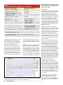
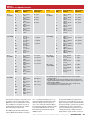
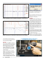
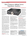
TechnicalReview Product by Mark Spencer, WA8SME Mark J. Wilson, K1RO, [email protected] Array Solutions AIMuhf Vector Impedance Analyzer A look at a useful test instrument that offers lab-quality measurements at an affordable price. in measurement mode and about 50 mA when idle, so plan ahead and have enough batteries on hand.) Battery operation may be useful when it is necessary to “float” the analyzer and a laptop isolated from ground. It occurred to me that portable operation would be a lot easier if a minimal smartphone app were available to invoke specific functions, display the data and store it for transfer to a PC later on. Reviewed by H. Ward Silver, NØAX ARRL Contributing Editor [email protected] Over the last couple of years, you may have seen references or ads for VNA instruments. What is a VNA? The vector network analyzer (VNA) doesn’t do much that you can’t also do with an oscilloscope and a signal generator — it just makes it easier. A full VNA can make both reflection and transmission measurements. Reflection measurements describe what happens to a signal when it encounters a circuit or load (usually referred to as a DUT — device under test). SWR and return loss are reflection measurements. Transmission measurements describe what happens to a signal as it is transmitted from one port of a circuit to another. Amplifier gain and filter attenuation are examples of transmission measurements. Both types of measurements are most useful over a range of frequencies, and modern VNAs use DDS (direct digital synthesis) techniques to make measurements from audio frequencies to the GHz region. Most antenna measurements of interest to hams are reflection measurements — SWR, return loss or impedance. Array Solutions’ AIMuhf is called a Vector Impedance Analyzer because it makes reflection measurements but does not perform transmission measurements. This simplifies the instrument, its calibration and the data it provides. The AIMuhf generates and digitizes the RF signals, and a host computer running the companion software performs all the control and data crunching functions. The AIMuhf can also be used to directly measure the values of components such as inductors, capacitors, baluns and resistors. The self resonant frequencies of inductors and capacitors can also be determined. AIMuhf Overview The AIMuhf is a version of the AIM 4170 analyzer that extends its performance to 1 GHz.1 (The AIM 4170 is specified to 180 MHz.) See Table 1 for this unit’s specifications. There is an active user’s forum at aim4150.proboards.com/index. cgi?board=analyzer, and there is also a good support page at homepage.ntlworld. com/wadei/aim4170.htm. The presentation by G3NRW dated 2011 is particularly good at outlining the instrument’s capabilities and how they can be applied to the various technical needs of hams. The analyzer was originally described in QST by its designer, Bob Clunn, W5BIG.2 In addition to the AIM line of analyzers, Array Solutions offers a W5BIG-designed VNA — the VNA 2180 — which has also been extended to cover the UHF range.3 An external computer is required to operate the unit and to record and display measurement results. A laptop or tablet PC with a USB interface can be used. The unit can be powered from a standalone ac supply or it can be battery operated. (Current draw is 350 to 400 mA You can get a preview of the software by downloading it from the w5big.com website and running it in demo mode. Setup and Calibration The unit requires you to download and install the host software and a USB driver from the company website to your PC. This was straightforward on a spare Dell B130 laptop running Windows XP Service Pack 3 — with one exception. In my case, setup involved some head-scratching about proper configuration of the USB COM port as the host software was unable to find the analyzer at first. Eventually I was able to prevail by manually changing the USB interface to act as COM1. To be fair, I had a number of USB COM port drivers on my system already and that may have confused the analyzer and host software. This should be more straightforward with newer versions of the Windows operating system. The specified power-up sequence for the host software and the analyzer must also be followed for them to get connected properly. Once 1J. Hallas, W1ZR, “Three Antenna System Measurement Devices,” Product Review, QST, Aug 2007, pp 67-73. Product Reviews are available to ARRL members online at www. arrl.org/product-review. 2B. Clunn, W5BIG, “An Antenna Impedance Meter for the High Frequency Bands,” QST, Nov 2006, pp 28-32. 3P. Salas, AD5X, “Array Solutions VNA 2180 Vector Network Analyzer,” Product Review, QST, Mar 2011, pp 57-59. QST ® – Devoted entirely to Amateur Radio Bottom Line The AIMuhf Vector Impedance Analyzer offers reflection and impedance-only measurements for dedicated and popular measurement functions. The host software creates easy-to-read displays and easy-to-use preprogrammed functions. www.arrl.org November 2012 57 the host computer software. I kept the manual and Help windows open at all times and referred to them regularly. Table 1 AIMuhf Vector Impedance Analyzer, serial number 6169 Manufacturer’s Specifications Measured in the ARRL Lab Frequency range: 0.005-1000 MHz. As specified. SWR measurable range: 1:1-20:1. As specified. Impedance range: 1-5000 W (up to 60 MHz); 1-2000 W (up to 200 MHz); 1-600 W (up to 1 GHz). As specified. Impedance accuracy: Not specified. See Table 2. Drift: Not specified. No discernible drift after 1 hour. Output power: – 27 to – 17 dBm. –48 dBm to –18.0 dBm. 10 kHz, – 18.5 dBm; 300 MHz, –24.5 dBm; 1 GHz, –48 dBm.* Power requirements: 7 to 15 V dc at 380 mA. 368 mA (measurement mode), 381 mA (tune mode), 34 mA (idle) at 13.8 V dc. Minimum operating voltage, 7.5 V dc. Applications I have to include a disclaimer: There are literally hundreds of measurements that could be performed with this instrument and more streamlined methods of operating it than I describe here. Only having the unit for a limi ted time, I cannot claim to have explored every option or used the AIMuhf in an optimum way. Its power quickly became apparent as I navigated the menus and selections. As with any powerful instrument or full featured radio, you must spend some time learning about the analyzer and measurement techniques to use them most effectively. Size (height, width, depth): 1.7 × 5.1 × 5.0 inches (including protrusions); weight, 13.6 oz. Price: AIMuhf with ac power supply, USB cable and calibration loads, $895. AIM-PC padded carrying case, $39. *Power of desired signal only, measured with HP-8563E spectrum analyzer. Output is rich in harmonics that result in a higher power measurement with a broadband power meter and no filtering. the AIMuhf hardware and software were configured and calibrated, all of the operating functions and processes ran smoothly and quickly on my relatively old laptop that had several other USB gadgets installed. The instrument is calibrated by placing a termination (open, short or standard resistance) on the measurement port. Through the use of the AIMuhf line extension function, the instrument can calibrate out the effects of long cables so that the analyzer can stay in the shack while making measurements of remote antennas or circuits. It has the ability to store and recall sets of calibration data so that you can switch among several different configurations of the instrument and whatever is being tested. Following an initial three-step (OPEN, SHORT, LOAD) calibration process, taking measurements was simple because there is a dedicated menu option for just about every common measurement. (The entire menu tree is illustrated at www.w5big.com/AIM_menu.png.) The extensive capabilities and functions of the analyzer are described in a 125-page PDF manual or in the Help files associated with Another particularly nice feature of the AIMuhf host software is the ability to display the differences between two scans for impedance magnitude and angle, resistance and reactance. It would be a great enhancement to the software to extend that capability to SWR, since it would be easy to see the effects of antenna tuning or whether an antenna has changed over time. The re-scan function can be used to see the immediate effects of adjustments and tuning. Figure 1 is a measurement of my multiband dipole antenna and antenna tuner made using the AIMuhf. I used the frequency range that was preprogrammed for the 20 meter band (13.9-14.5 MHz) although I could have entered any range manually. Six variables were automatically displayed: SWR and return loss with scales on the left side of the graph and the impedance parameters Z (magnitude and phase), R, and X with scales on the right side of the graph. That’s a pretty complete picture. The output can be saved in a variety of formats from images to spreadsheet files. The AIMuhf does not save data in the Touchstone S1P format and that would be a useful enhancement in the future to allow the data to be used by simulation and analysis programs. The graph in Figure 2 illustrates the usefulness of highlighting the amateur bands on a wide frequency sweep. Measured input SWR (top) and return loss (bottom) for a Dunestar 300-21 15 meter band-pass filter are displayed as measured across the preprogrammed HF frequency range (3-31 MHz). You can clearly see each amateur band highlighted by vertical blue bars. While frequency markers aren’t shown on this particular graph, they are available if desired. Figure 1 —The AIMuhf analyzer measurement of SWR, return loss and complex impedance — both magnitude/phase and resistance/reactance in a single scan of a multiband antenna through an antenna tuner. Only the parameters of interest need to be displayed. 58 November 2012 ARRL, the national association for Amateur Radio® In Figure 3, I’ve connected my handheld Arrow VHF/UHF satellite antenna to the analyzer and performed a manually programmed sweep from 140 to 460 MHz. The AIMuhf allows the user to set the measure- www.arrl.org Table 2 Impedance and SWR Measurements Load Frequency Array Solutions Agilent 4291B (MHz)AIMuhf 1(reference)2 50 W 3.5 49.7 + j0.0 W (1:1 SWR) (1.0:1) 14 49.7 + j0.0 W (1.0:1) 28 49.8 + j0.0 W (1.0:1) 50 49.7 + j0.0 W (1.0:1) 144 49.8 + j0.2 W (1.0:1) 440 49.7 + j0.7 W (1.0:1) 902 49.7 + j0.7 W (1.0:1) 50 + j0 W3 5 W 3.5 5.0 – j0.5 W (10:1 SWR) (10.1:1) 14 5.0 – j0.1 W (10.1:1) 28 5.0 – j0.2 W (10.1:1) 50 5.0 – j0.4 W (10.1:1) 144 4.9 – j0.9 W (10.2:1) 440 5.1 – j2.7 W (9.9:1) 902 5.5 – j5.3 W (9.2:1) 5.1 + j0.0 W 25 W 3.5 24.9 + j0.0 W (2:1 SWR) (2.0:1) 14 25.0 + j0.2 W (2.0:1) 28 25.0 + j0.3 W (2.0:1) 50 25.0 + j0.6 W (2.0:1) 144 25.2 + j1.9 W (2.0:1) 432 27.8 + j7.1 W (1.9:1) 902 39.1 + j16.4 W (1.6:1) 25.1 + j0 W 100 W 3.5 99.3 + j0.0 W (2:1 SWR) (2.0:1) 14 99.4 – j0.0 W (2.0:1) 28 99.4 – j0.1 W (2.0:1) 50 99.3 – j0.3 W (2.0:1) 144 99.4 – j1.4 W (2.0:1) 440 100.3 – j1.5 W (2.0:1) 902 100.7 + j0.7 W (2.0:1) 100 – j0.2 W ment interval as frequency steps. I discovered the antenna seems to want to work at 300 MHz (close to the second harmonic of 2 meters) and I’ll have to check that out. One of the side benefits of using this type of instrument is the unexpected discovery. The AIMuhf performs time-domain reflectometry (TDR) measurements in an indirect 50 + j0 W 50 + j0 W 50 + j0 W 5.1 + j0.2 W 5.1 + j0.4 W 5.2 + j0.7 W 25.1 + j0.2 W 25.1 + j0.4 W 25.1 + j0.7 W 100 – j0.9 W 100 – j1.8 W 99.9 – j3.1 W Load Frequency Array Solutions Agilent 4291B (MHz)AIMuhf(reference) 200 W 3.5 199.7 – j0.3 W (4:1 SWR) (4.0:1) 14 199.8 – j0.5 W (4.0:1) 28 199.8 – j1.1 W (4.0:1) 50 199.5 – j2.7 W (4.0:1) 144 199.4 – j7.7 W (4.0:1) 440 197.7 – j17.3 W (4.0:1) 902 192.4 – j21.2 W (3.9:1) 201 – j1.2 W 1000 W 3.5 993.6 – j10.9 W (20:1 SWR) (19.9:1) 14 990.7 – j29.7 W (19.8:1) 28 988.7 – j61.8 W (19.5:1) 50 977.6 – j109.8 W (9.8:1) 144 884.2 – j301.9 W (19.8:1) 440 508.3 – j479.4 W (19.3:1) 902 263.8 – j380.4 W (16.4:1) 998 – j33 W 50 – j50 W 3.5 49.5 – j46.6 W (2.62:1 SWR) (2.5:1) 14 47.7 – j52.1 W (2.8:1) 28 50.5 – j47.3 W (2.5:1) 50 – j47 W 50 + j50 W 3.5 52.1 + j50.4 W (2.62:1 SWR) (2.5:1) 14 52.8 + j48.8 W (2.5:1) 28 65.2 + j51.7 W (2.5:1) 52 + j50 W 201 – j4.8 W 200 – j9.4 W 199 – j16 W 981 – j127 W 935 – j239 W 825 – j373 W 48 – j52 W 51 – j48 W 53 + j48 W 65 + j51 W Notes: 1The AIMuhf has the option to display either the series or parallel equivalent values. 2The SWR loads constructed in the ARRL Lab were measured on an Agilent 4291B Impedance Analyzer by ARRL Technical Advisor John Grebenkemper, KI6WX. 3An HP 11593A precision termination was used for the 50 W tests. This termination has a wide frequency range. way — by taking wide-band frequency domain measurements and then using a mathematical technique called a transform to create a time-domain measurement. This is how stub electrical length or distance to fault is measured. TDR functions are the only time-domain measurements made by the AIMuhf analyzer. I put the unit in TDR mode and attached a short piece of coaxial cable open on one end. Figure 4 shows the results of the DISTANCE-TOFAULT function with a velocity factor specified as 0.660. Since my cable’s actual velocity factor was unknown, I was pleased to see the calculated length agree with the measured length within a couple of inches. Accuracy of QST ® – Devoted entirely to Amateur Radio www.arrl.org November 2012 59 Figure 4 — The AIMuhf analyzer performs time-domain reflectometry (TDR) functions, such as distance-to-fault and electrical length measurements of a section of feed line. ing Q and bandwidth, and designing and testing matching networks. It’s a very powerful instrument in a small package. Figure 2 — The AIMuhf host software can highlight the amateur bands on a wide-band scan as shown in this SWR and return loss measurement of a Dunestar 300-21, 15 meter band-pass filter. Summary The AIMuhf analyzer, with its single port, is intended for common antenna and transmission line applications. If your needs are less for a general-purpose analyzer and more for an enhanced antenna and transmission line analyzer, you’ll like using the AIMuhf. By preprogramming so many common functions into the host software, it greatly lowers the barrier to using those measurements on a dayto-day basis. The display outputs are easy to read with units and scales that tell you what you need to know. It is a testament to what advances in communication technology offer when the functionality displayed by this instrument is available brand-new to the amateur at less than the cost of a middle-of-the-line radio. Figure 3 — A wide-band scan of a dual band Arrow satellite Yagi antenna from 140 to 460 MHz. electrical length measurements depends on the accuracy of the velocity factor, which can also be measured by the AIMuhf. Manufacturer: Array Solutions, 2611 North Beltline Rd, Suite 109, Sunnyvale, TX 75182; tel 214-954-7140; www.arraysolutions.com. See the Digital Edition of QST for a video overview of the AIMuhf Vector Impedance Analyzer. Lab Tests The accuracy of the AIMuhf as compared with an Agilent 4291B laboratory impedance analyzer was quite good as shown in Table 2. Measurements of known loads ranging from 5 to 1000 W, including loads with capacitive and inductive reactance, were taken at frequencies from 3.5 to 902 MHz and compared with the readings from the calibrated analyzer. I barely scratched the surface of what the AIMuhf can do. It makes measurements instantly for which I would have to cobble together several instruments and an oscilloscope. It is all ready to go to work making transmission line stubs, synchronous 1 ⁄4- and 1⁄12-wavelength transformers, measur60 November 2012 ARRL, the national association for Amateur Radio® www.arrl.org DZKit HT-7 40 Meter AM Handheld Transceiver Reviewed by Bob Allison, WB1GCM ARRL Test Engineer [email protected] scrape the enamel coating off the ends of each piece of magnet wire before soldering the wires to the board. I was astonished to learn of The DZ Company’s HT-7 40 Meter AM Handie-Talkie kit. The HT-7 reminds me of the 3 to 6 MHz World War II-era walkie-talkies that struggled to go a few miles with their battery powered vacuum tube circuitry and short antennas. My astonishment soon turned to curiosity: How well does it work with its 2 W RF output power and a reasonably small antenna attached? Is the modulation quality acceptable? I had to know! The tricky step for me was stripping and dressing the ends of three small diameter coax cables. The manual shows a pictorial of the needed coaxial cable preparation, but my first attempt ended with cutting through the shield of the cable. Fortunately, the kit includes a couple of extra inches of coax for a second attempt. I recommend using a small razor knife for delicately cutting through the outer jacket. The HT-7 is a kit, so I’d have fun building it too. I asked our Product Review Editor to order one, along with the optional 4000 mA/h Lithium-ion (Li-ion) battery pack, 57 inch whip antenna and whip antenna tuner. Out of the Box The experience of opening the HT-7’s shipping carton was a flashback to my Novice days when I built a Heathkit DX-60B transmitter. The parts are well packed in plastic envelopes (Figure 5). The detailed manual looks nearly identical to a typical 1970s Heathkit manual, complete with a line drawing of a father watching over his kit-building son. Newer builders will appreciate the assembly guidelines and practical advice on soldering and safety. The manual is available for download from the DZKit website if you’d like to take a look. The manual includes a well illustrated list of all 34 components to be soldered and 37 hardware parts. I was relieved to find all surface mount components already soldered on the two provided circuit boards. My new after-hours project started with carefully reading the manual, taking inventory and separating the various parts by placing them into an empty jumbo egg carton. I savored every step of construction and every solder joint, penciling a check mark in the box next to each step exactly as I did in my youth. In just over five hours, I was ready for the test and adjustment part of the instruction manual. DZ provides a chart of the expected dc voltages at various points on the circuit boards. With fingers crossed, I applied 13.8 V dc to the external power jack (reverse polarity protected) and turned on my HT-7 for the first time. Unlike my old DX-60B, no smoke escaped! Voltages were as expected and I proceeded to adjust the receiver sensitivity, transmit carrier level and modulation level as instructed. It’s comforting to know that if the builder has trouble at this point, The DZ Company provides troubleshooting advice and, for a fee, will correct errors or repair the HT-7. Final assembly involves integrating the circuit boards and speaker into the case, as shown in Figure 6. It was a bit tight, but all pieces came together as instructed except for the alignment of the push-to-talk (PTT) button and the metal slot in the case. Here, I had to use a metal file to make the slot slightly larger. Once completed, the HT-7 resembles a 1960s era walkie-talkie (Figure 7). The 21⁄2 by 13⁄4 inch front facing speaker provides plenty of audio. The built in electret microphone is mounted flush just below the speaker. The PTT switch is located at the left side of the aluminum case. The VOLUME/ON/OFF control, BNC antenna connector, microphone jack, monaural headphone jack and a 12 V dc external power/charging jack are located on the case top. The microphone jack is compatible with high or low impedance microphones, except those that require external dc voltage. When a microphone is plugged into the external microphone jack, the internal electret microphone is disconnected and voltage is removed from the line. The bottom of the case opens up to expose the battery compartment. Once placed inside the HT-7, the optional internal battery pack is charged through the external dc power/charging jack. The internal battery connection and external dc/charging jack are reverse polarity protected by a hefty diode. Adjustments Before Lab testing, I checked both receive and transmit functions in the field. I did this by driving from my home to the nearby Nathan Hale Homestead, a safe and scenic place to operate portable. With the assistance of my wife Kathy, KA1RWY, and with the optional whip and antenna tuner attached to the BNC Construction I had no trouble following the excellent instructions. I would like to add one detail regarding the two small toroids: Don’t forget to Bottom Line The DZKit HT-7 is a fully functional single channel, crystal controlled 40 meter AM handheld transceiver kit that is fun to build and fun to operate. Users must accept the challenges of making contacts with low power and limited antennas while portable. Figure 5 —The HT-7 kit pieces are well packed and organized. Surface mounted components are already soldered to the PC board. QST ® – Devoted entirely to Amateur Radio www.arrl.org November 2012 61 A Portable Loop Antenna Figure 6 — The final assembly steps involve mounting the PC boards, speaker and optional battery inside the case. the first time. Back at the shack, I found it best to adjust the carrier (RV1) to 600 mW RF output power and then adjust the microphone preamp gain (RV2) for maximum gain without distortion. With the internal 11.1 V dc battery pack, I measure slightly over 1.6 W PEP RF output power. Tests the following day with W1AW Station Manager Joe Carcia, NJ1Q, confirmed that my HT-7 was now transmitting clear audio. Lab Testing The receiver current consumption is comparable to modern VHF/UHF handheld transceivers. With the optional 4000 mA/h battery pack, I could probably operate this transceiver for a couple of days before a recharge would be needed. Spurious emission suppression is significantly better than specified, and the HT-7 met its specified RF power output of 2 W PEP with 13.8 V dc applied. Figure 7 — Here’s the finished HT-7 with its optional Miracle Antenna tuner and whip. connector, I made my first contact over the 11⁄2 mile path. Kathy reported muffled and distorted audio, but she could understand me. Reception at my end was as expected: loud and clear. The muffled audio was troubling, but as it turned out the manual’s instruction of “adjust RV1 and RV2 on the HT-7-1 circuit board for best audio” is correct. I just didn’t get it right 62 November 2012 The receiver sensitivity did not meet the specified 1 µV. I can comfortably hear an 8 µV signal, but can barely hear a 2 µV signal. No audio distortion is noticeable as the input signal decreases to the point of fading out. Reduced sensitivity is not entirely detrimental, considering the low transmitter power. Realistically, the HT-7 will be heard by stations that are received loudly through the speaker. On the Air To make my first distant contact easier, I attached the HT-7 to W1AW’s 2 element 40 meter Yagi antenna, perched atop its 120 foot tower. Without effort, I was able to contact well known AM enthusiast Tim Smith, WA1HLR, in Skowhegan, Maine (a distance of 250 miles). Tim reported an S8 signal with good transmitted audio. A half-hour QSO ensued, pointed with laughter and appreciation for the novelty of a low power, handheld AM transceiver. At home, using my full size dipole antenna, ARRL, the national association for Amateur Radio® As an alternative to the optional whip antenna and tuner from Miracle Antenna, I decided to build a magnetic loop antenna based loosely on an article by Rob Capon, WA3ULH (now W3DX).† Check out Rob’s article for a more complete discussion. My antenna support consists of a child’s plastic exercise hoop (originally filled with plastic beads) purchased at a toy store for $5.99. The hoop is secured with cable ties to a length of 1 inch PVC pipe ($1.49 at a nearby home center). The large loop, 10 feet in circumference, is made from a conductor threaded inside the plastic hoop. You can use the shield from a length of coax or a heavy gauge wire. I found just enough #4 AWG in the ARRL Lab junk box to do the trick. The small loop, made from RG-8X coax shield, is 2 feet in circumference. The coax feed line connects to the small loop, and the two loops have no electrical connection. The HT-7 operates on a single frequency, so a fixed value of capacitance at the top of the large loop makes the overall design simple and inexpensive. By trial and error, I found that 152 pF of capacitance made the antenna resonant at 7.290 MHz. Since the HT-7 has an RF output of 2 W or less, ceramic disc capacitors with a rating of 1 kV were chosen. To get the needed value, I used two 4.7 pF capacitors in series, and then connected these in parallel with a 150 pF capacitor. The capacitors appear to run cool enough to not change value during transmissions, ensuring a stable resonant frequency. Figure 8 shows the finished loop connected to the HT-7’s BNC connector with a short length of coax, greatly reducing mechanical stress on the connector. The overall cost of the loop antenna is less than $10, provided that you have some scraps of coax cable. A detailed drawing of the loop and additional photos are available in the Digital Edition of QST. Field testing 2 miles away from the ARRL Lab indicated this antenna radiated equal to or better than the review antenna system. In one location, signals from the loop were considerably stronger at the Lab than signals from the whip and tuner. On receive, I have heard several stations clearly while using this antenna, but as of this writing have not worked anyone with the HT-7. More testing is needed to determine the overall performance. The loop offers an easy alternative to the optional whip antenna. †R. Capon, WA3ULH, “You Can Build: A Compact Loop Antenna for 30 through 12 Meters,” QST, May 1994, pp 33-36. Past QST articles are available to ARRL members online at www.arrl.org/qst. www.arrl.org Table 3 DZKit HT-7, serial number 0901A0028 Manufacturer’s Specifications Measured in the ARRL Lab Frequency coverage: 7.290 MHz. Receiver and transmitter, 7.290 MHz. Mode: AM. As specified. Power consumption: 50 mA (receive), 500 mA (transmit) at 10-12 V dc. With 13.8 V dc external power: Receive, 76 mA (max audio, no signal), transmit, 700 mA. With 11 V dc internal battery, receive 72 mA, transmit 590 mA. Receive sensitivity: 1 µV. For 10 dB S+N/N: 8 µV. Audio response: 6 kHz. 400-4310 Hz (7820 Hz bandwidth)* RF power output: 2 W. 2 W PEP at 13.8 V dc, 1.6 W PEP with internal battery. Spurious suppression: 45 dB. 60 dB. Transmit IMD: <–20 dB. As specified. Size (height, width, depth): 7.4 × 3.2 × 2.1 inches (including protrusions); weight, 1.5 pounds including optional battery. Price: HT-7: $169.99; HTA-1 rechargeable Li-ion battery pack, $45; HTA-2 whip antenna: $30; HTA-3 inline antenna tuner, $124.95. *Overall response, excluding a 10 dB audio peak at 3200 Hz. Figure 8 — Fellow ARRL Lab Engineer Mike Gruber, W1MG, with the HT-7 and portable loop antenna. the HT-7 receives well enough to pick up the typical atmospherics and man-made noises commonly heard on 40 meters. Amateur AM stations are received loud and clear, provided that received stations are transmitting on or close to 7.290 MHz, the HT-7’s single crystal controlled operating frequency. At a minimum, the HT-7 makes a good 7.290 MHz monitor. With good conditions, I expect to make contacts with my dipole antenna — but the HT-7 is designed for walking and talking. I found the optional whip and antenna tuner (a 57 inch whip and Miracle Antenna Ducker IL model tuner) to be adequate for local contacts. I also decided to experiment with a loop antenna for walking and talking (see sidebar). Although some amateurs will dismiss the HT-7 as an AM novelty, it’s really a cleverly designed modern transceiver dressed as a Model T. The HT-7 builder will gain good experience in preparation for building other kits. The experience of reliving my Novice days while building this Heathkit-like kit was priceless and the completed transceiver does in fact, function well. I found it to be pure fun! Manufacturer: The DZ Company, 4321 Eisenhower Blvd, Loveland, CO 80537; tel 877- 426-7422; www.dzkit.com. See the Digital Edition of QST for a video overview of the DZKit HT-7. The optional 11.1 V, 4000 mA/h Li-ion battery pack is well worth the $45 price tag. It has a built-in charging circuit that prevents overcharging and discharging and is reverse polarity protected. It can be charged with a 12 V dc power supply that is current limited to 4 A or less. I’ve charged mine using a 12 V dc, 1 A wall charger with good results. Wrapping It Up The HT-7 is a basic radio designed to work on one channel. Its boxy shape looks rather antiquated, and that adds to the charm. Don’t expect memory channels, VFO, a fancy display or computer interface. If you’re lucky, you might even make a contact with it while operating portable. QST ® – Devoted entirely to Amateur Radio www.arrl.org November 2012 63 Technical Short Takes by Mark Spencer, WA8SME Steve Ford, WB8IMY, [email protected] West Mountain Radio RIGrunner 4005i If you need access by a tablet or smartphone, this RIGrunner can also be configured to function as its own DHCP server. This feature is also used for the initial setup, which can get a little technical unless you are somewhat network savvy. West Mountain Radio’s technical support staff was very helpful in getting my head around the “hard stuff,” but the user manual is complete and well-organized. Read it first and follow instructions and I predict you’ll have no trouble. By Pete Smith, N4ZR 96 Willow Well Ln Kearneysville, WV 25430-5811 [email protected] Remote control of Amateur Radio stations has been with us since the earliest VHF repeaters, but recently there has been a resurgence of interest in remotely controlling stations for other purposes. Communities with covenants effectively prohibiting outside antennas, apartment dwelling, and other aspects of modern life have led to development of a range of products intended specifically to permit operating an Amateur Radio station hundreds or thousands of miles away. So what does this have to do with West Mountain Radio, long known for its interfaces and power-related products? The answer lies in the RIGrunner 4005i, a highend addition to their power distribution line, one that is specifically designed for remote control applications. The 4005i is a compact, nicely designed unit, but you might at first dismiss it as just another pretty face. It is only 8 inches long and 15⁄8 inches high, so it will fit easily into any station and has full switching and monitoring of all your power needs. What’s really new here are the remote control and monitoring features utilizing an internal web server. You can use the 4005i to remotely control power distribution for an entire Amateur Radio station, even without a computer at the remote end. Both standard wired Ethernet and a wireless WiFi option are available, and you can set it up for access across a network, and even by a tablet or smartphone. The Basics The RIGrunner 4005i is powered off the station power supply, and distributes up to 40 A (30 A continuous) of 13.8 V power to five individually switched, soft-fused circuits, through Anderson Powerpole nodes located on the back of the unit. You can adjust the level at which they trip, and they can be reset locally or remotely. On site, each node can be switched on or off by pushing a button, and two pushes will reset its fuse. A small LCD display monitors voltage and current on each node, as well as a complete set of network The RIGrunner remote configuration screen. parameters. While five nodes may seem small compared with other distribution panels, there’s no reason you couldn’t attach a conventional distribution panel to one node and connect all your small gadgets there. All West Mountain Radio power distribution products use Powerpole connectors, and since that’s what I use, it took less than a minute’s work to replace my old “dumb” distribution panel with the 4005i. One nice touch — convenient little plastic clips are supplied to hold the connectors together, to prevent them from accidentally disconnecting. Remote Capabilities All these touches are nice, but what makes the 4005i unique are its remote operation features. My home network is WiFi, and hooking up to it was easy. For remote access, it would be necessary to open a “window” in your network firewall, a simple enough procedure. One key feature of this unit is that it remembers its state when powered down, so even if ac power were to fail at a remote site, as soon as it is restored, the router and the RIGrunner will reboot and continue as before. My web browser quickly gave me access to four web pages served by the 4005i. They are: Home, where you monitor and control each node’s status XML, where you see the raw form of the monitored data — intended for future use with external software. Expansion, which controls a DIN port on the back of the unit where various serial and analog signals are available for connection to future add-ons. Config, where you can set the descriptive name of each node, set the soft fuse current levels, adjust your network configuration, set username/password and even set up e-mail alerts to be sent automatically if one of the soft fuses has tripped. This is a new product, and information about using the XML output and the expansion port is quite sketchy. I think you can expect West Mountain Radio to roll out firmware, and possibly hardware too, intended to utilize the XML and expansion port capabilities. The 4005i’s firmware can be updated across the Internet, so users can be assured of keeping up with new features as they are released. The RIGrunner 4005i is a compact, thoughtfully designed and complete power control and distribution system that will be especially attractive to remote station operators. To my knowledge, it is currently unique in the Amateur Radio field. Manufacturer: West Mountain Radio, 1020 Spring City Dr, Waukesha, WI 53186; tel 262-522-6503; www.westmountainradio. com. $279.95; WiFi option $50. QST ® – Devoted entirely to Amateur Radio www.arrl.org November 2012 69