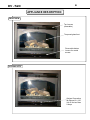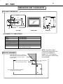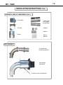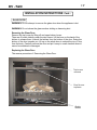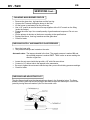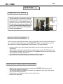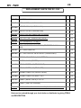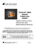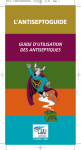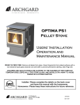
1
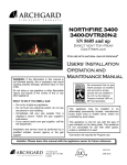
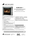
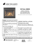
DV - 520
Direct Vent Gas Fireplace
For use with natural gas or propane*
WARNING: If the information in this manual is
not followed exactly, fire or explosion may result
causing property damage, personal injury or loss
of life.
Do not store or use gasoline or other flammable
vapors and liquids in the vicinity of this or any
other appliance.
USERS’ INSTALLATION
OPERATION AND
MAINTENANCE MANUAL
WHAT TO DO IF YOU SMELL GAS:
∗ Do not try to light any appliance.
∗ Do not touch any electrical switch; do not use
any phone in your building.
∗ Immediately call your gas supplier from a
neighbor’s phone. Follow the gas supplier’s
instructions.
∗ If you cannot reach your gas supplier, call the
fire department.
Installation and service must be performed by a
qualified installer, service agency or the gas
supplier.
This appliance may be installed in an
aftermarket permanently located,
manufactured home (USA only) or mobile
home, where not prohibited by local codes.
This appliance is only for use with the type
of gas indicated on the rating plate. This
appliance is not convertible for use with
other gases, unless a certified kit is used.
*Conversion kit required for Propane use
Installer: Please leave this manual with the appliance owner for future reference
7116 Beatty Dr
Mission, BC V2V 6B4
Canada
200-0160
FEBRUARY 2005
Requirements for the state of Massachusetts
5.08: Modifications to NFPA-54, Chapter 10
(2) Revise 10.8.3 by adding the following additional requirements:
(a) For all side wall horizontally vented gas fueled equipment installed in every dwelling, building or structure used in whole or in part for residential
purposes, including those owned or operated by the Commonwealth and where the side wall exhaust vent termination is less than seven (7) feet
above finished grade in the area of the venting, including but not limited to decks and porches, the following requirements shall be satisfied:
1. INSTALLATION OF CARBON MONOXIDE DETECTORS. At the time of installation of the side wall horizontal vented gas fueled equipment, the
installing plumber or gasfitter shall observe that a hard wired carbon monoxide detector with an alarm and battery back-up is installed on the floor
level where the gas equipment is to be installed. In addition, the installing plumber or gasfitter shall observe that a battery operated or hard wired
carbon monoxide detector with an alarm is installed on each additional level of the dwelling, building or structure served by the side wall horizontal
vented gas fueled equipment. It shall be the responsibility of the property owner to secure the services of qualified licensed professionals for the
installation of hard wired carbon monoxide detectors
a. In the event that the side wall horizontally vented gas fueled equipment is installed in a crawl space or an attic, the hard wired carbon monoxide
detector with alarm and battery back-up may be installed on the next adjacent floor level.
b. In the event that the requirements of this subdivision can not be met at the time of completion of installation, the owner shall have a period of
thirty (30) days to comply with the above requirements; provided, however, that during said thirty (30) day period, a battery operated carbon monoxide detector with an alarm shall be installed.
2. APPROVED CARBON MONOXIDE DETECTORS. Each carbon monoxide detector as required in accordance with the above provisions shall
comply with NFPA 720 and be ANSI/UL 2034 listed and IAS certified.
3. SIGNAGE. A metal or plastic identification plate shall be permanently mounted to the exterior of the building at a minimum height of eight (8) feet
above grade directly in line with the exhaust vent terminal for the horizontally vented gas fueled heating appliance or equipment. The sign shall
read, in print size no less than one-half (1/2) inch in size, "GAS VENT DIRECTLY BELOW. KEEP CLEAR OF ALL OBSTRUCTIONS".
4. INSPECTION. The state or local gas inspector of the side wall horizontally vented gas fueled equipment shall not approve the installation unless,
upon inspection, the inspector observes carbon monoxide detectors and signage installed in accordance with the provisions of 248 CMR 5.08(2)(a)
1 through 4.
(b) EXEMPTIONS: The following equipment is exempt from 248 CMR 5.08(2)(a)1 through 4:
1. The equipment listed in Chapter 10 entitled "Equipment Not Required To Be Vented" in the most current edition of NFPA 54 as adopted by the
Board; and
2. Product Approved side wall horizontally vented gas fueled equipment installed in a room or structure separate from the dwelling, building or structure used in whole or in part for residential purposes.
(c) MANUFACTURER REQUIREMENTS - GAS EQUIPMENT VENTING SYSTEM PROVIDED. When the manufacturer of Product Approved side
wall horizontally vented gas equipment provides a venting system design or venting system components with the equipment, the instructions provided by the manufacturer for installation of the equipment and the venting system shall include:
1. Detailed instructions for the installation of the venting system design or the venting system components; and
2. A complete parts list for the venting system design or venting system.
(d) MANUFACTURER REQUIREMENTS - GAS EQUIPMENT VENTING SYSTEM NOT PROVIDED. When the manufacturer of a Product Approved side wall horizontally vented gas fueled equipment does not provide the parts for venting the flue gases, but identifies "special venting systems", the following requirements shall be satisfied by the manufacturer:
1. The referenced "special venting system" instructions shall be included with the appliance or equipment installation instructions; and
2. The "special venting systems" shall be Product Approved by the Board, and the instructions for that system shall include a parts list and detailed
installation instructions.
(e) A copy of all installation instructions for all Product Approved side wall horizontally vented gas fueled equipment, all venting instructions, all parts
lists for venting instructions, and/or all venting design instructions shall remain with the appliance or equipment at the completion of the installation.
For the State of Massachusetts, installation and repair must be done by a plumber or gasfitter licensed in the Commonwealth of Massachusetts.
For the State of Massachusetts, flexible connectors shall not exceed 36 inches in length.
The State of Massachusetts requires the installation of a carbon monoxide alarm in accordance
with NFPA 720 and a CO alarm with battery back up in the same room where the gas appliance is
installed.
For the State of Massachusetts the appliances individual shut – off must be a t-handle type valve.
CONTENTS
Introduction
4
General Information
5
Appliance Description
6
Dimensions and Clearances
7
Installation Instructions
8 - 17
Operation Instructions
19 - 20
Maintenance
21
Troubleshooting Instructions
22– 23
Wiring Diagrams
24
Servicing
25 - 27
Replacement Parts
28
Warranty
29
Warranty Registration Form
31
CAUTION
Due to high temperatures, the appliance should be located out of traffic and away from
furniture and draperies.
Children and adults should be alerted to the hazards of high surface temperature and stay
away to avoid burns or clothing ignition.
Young children should be carefully supervised when they are in the same room as the
appliance.
Clothing or other flammable material should not be placed on or near the appliance.
Do not operate with cracked or broken glass. Be careful not to strike or slam the glass.
Any safety screen or guard removed for servicing an appliance must be replaced prior to
operating.
Installation and Repair should be done by a qualified service person. The appliance should
be inspected before use and at least annually by a professional service person. More
frequent cleaning may be required due to excessive lint from carpeting, bedding materials, et
cetera. It is imperative that the control compartments, burners and circulating air
passageways of the appliance are kept clean.
Patents Pending
4
DV - 520
INTRODUCTION
Congratulations on choosing an Archgard fireplace.
The Northfire DV-520 is one of the most advanced direct vent fireplaces available. It is
solidly designed using the latest technology and manufactured to the highest quality. It
is our aim to provide you with an appliance for many trouble-free years of reliable
service.
Some of the many features are:
Product Classification
The DV-520 is classified as a decorative gas appliance.
Flame Picture
The DV-520 has one of the more realistic flame pictures
of any gas fireplace; it uses more expensive ceramic
fiber (glows when impinged with flames) log set.
Solid Construction
The DV-520 is constructed mainly of heavy gauge
galvanized and aluminized steel for long life and
durability.
Standard “ON/OFF”
The gas control system is “remote” ready for your
optional millivolt wall switch or wireless remote control.
Please read the manual carefully prior to installation and operation of the
appliance. Proper installation, operation and maintenance of the appliance will
provide you with many years of enjoyment. We recommend you record the
following information:
Fireplace Model Number
Fireplace Serial Number
Date of Installation
Type of Gas Used by the Fireplace
Dealer’s Name
5
DV - 520
GENERAL INFORMATION
APPLIANCE CERTIFICATION
This appliance is tested and certified to the following US and Canadian gas appliance
standards.
- ANSI Z21.50b-1998/CSA 2.22b-M98, Vented Gas Fireplaces
- CAN/CGA-2.17-M91, Gas-Fired Appliances for Use at High Altitudes
Please contact Archgard Industries Ltd., if you have any questions regarding the certification of
this appliance.
INSTALLATION CODES
This appliance must be installed by a qualified gas appliance installer.
The installation must conform with the local codes or, in the absence of local codes, with the
current National Fuel Gas Code, ANSI Z223.1/ NFPA 54, in the US or Installation Code, CAN/
CGA-B149, in Canada. Electrical connections and grounding must conform with local code, or
current National Electrical code, ANSI/NFPA No. 70-1987, in the US and in Canada, the
current Canadian Electrical Code, CSA C22.1.
SPECIFICATIONS
Manifold Pressure
Min. Supply Pressure for
Purpose of Input Adjustment
Orifice Size
Natural Gas (NG)
Propane (LP)
3.5 in. W.C. ( 0.9 kPa)
10.0 in. W.C. (2.5 kPa)
4.5 in. w.c. (1.1 kPa)
11.0 in. w.c. (2.8 kPa)
#49 DMS (1.85 mm dia.)
#56 DMS (1.17 mm dia.)
15,000 BTU/hr
(4.4 kW)
15,000 BTU/hr
(4.4 kW)
120 VAC / 60 Hz / Less than 2A
120 VAC / 60 Hz / Less than 2A
0-4500 ft (0-1372 m)
0-4500 ft (0-1372 m)
3/16 in. (4.8 mm)
Fully open
Nominal Input Rating
Electrical Rating (Optional
Fan)
Elevation
Primary Air Opening
HIGH ALTITUDE INSTALLATION
When installing this appliance beyond 4500 ft. (1372 m) above sea level, the appliance must
be properly de-rated and installed according to local codes; in the absence of local codes, with
the current National Fuel Gas Code, ANSI Z223.1/ NFPA 54, in the US or Installation Code,
CAN/CGA-B149, in Canada.
6
DV - 520
APPLIANCE DESCRIPTION
FRONT VIEW
Top Louvers
(removable)
Tempered glass front
Removable bottom
louvers for control
access
OPTIONAL KITS
Optional Convection
fan Blower Kit (120
Volt 60 Hz less than
2 Amps
7
DV - 520
DIMENSIONS AND CLEARANCES
APPLIANCE DIMENSIONS
37 3/4”
4 3/4”
36”
1/2”
TOP VIEW
FRONT VIEW
30 3/8”
28 1/8”
16 1/2”
28 3/4”
16”
2 3/4”
SIDE VIEW
CLEARANCES TO COMBUSTIBLES:
BACK
SIDES
TOP
BOTTOM
ADJACENT SIDE WALL
MANTLE
VENT
0” to stand-offs
0” to stand-offs
0” to stand-offs
0”
0” to side of faceplate
see diagram
1” to outside side and bottom surface,
2” to outside top surface.
MANTLE CLEARANCE
Combustible mantle allowed in shaded area.
Mantle extension may be increased 1” (25mm)
for each additional 1” (25mm) increase in
clearance height.
Minimum Height From Top Surround:
6 1/4” (159 mm) with 8” mantle.
Minimum Height From Bottom of Appliance:
35” (890 mm) with 8” mantle.
NOTE: Low profile wooden
crowns and moldings above the
unit are not considered as
mantles. I.E. 1” or less protrusions on the upper mantle facing
are acceptable.
8” (203 mm)
8
DV - 520
INSTALLATION INSTRUCTIONS
PRECAUTIONS
•
This appliance must be installed by a qualified gas installer and the installation must
conform to the installation codes.
•
Provide adequate clearance around air openings of the appliance. Never obstruct front
openings.
•
Provide adequate clearances for proper operation and servicing of the appliance.
•
This appliance must be properly connected to a venting system.
•
This gas appliance must not be connected to a chimney serving a separate solid-fuel burning
appliance.
•
Do not use this appliance if any part has been under water. Immediately call a qualified
service technician to inspect the appliance and to replace any part of the control system and
any gas control which has been under water.
•
Caution: Label all wires prior to disconnection when servicing controls. Wiring errors can
cause improper and dangerous operation.
•
Verify proper operation after servicing.
•
Do not use substitute materials.
•
Do not abuse glass doors by striking or slamming shut.
•
Do not use abrasive cleaners.
•
Use only approved fireplace glass cleaner for cleaning your glass.
LOCATING GAS FIREPLACE
.
See ALLOWABLE TERMINATION LOCATIONS.
The fireplace may be installed in any location that maintains proper clearances to combustibles,
air conditioning ducts, electrical wiring and plumbing. Select a location that is accessible for
venting See section Allowable Termination Locations listed in this manual. When the appliance
is installed directly on carpeting, vinyl tile or other combustible materials, other than wood
flooring, the appliance must be installed on metal or wood panel extending the full width and
depth of the appliance.
GAS CONNECTIONS
Have your gas supplier or a qualified gas fitter run a gas supply line into the fireplace. The line
must be properly sized and fitted according to the installation codes. Immediately upstream of the
supply connection, the fitter shall provide an accessible manual shut-off valve and a 1/8 NPT
plugged tapping accessible for connection to a test gauge.
CAUTION: The appliance and its individual shutoff valve must be disconnected from the gas
supply piping system during any pressure-testing of that system at test pressures in excess of 1/2
psig (3.5 kPa). The appliance must be isolated from the gas supply piping system by closing its
individual manual shutoff valve during any pressure-testing of the gas supply piping system at test
pressures equal to or less than 1/2 psig (3.5 kPa). Failure to do so will damage the appliance’s gas
valve. Such damage is not covered by the manufacturer’s warranty.
9
DV - 520
INSTALLATION INSTRUCTIONS Cont...
Natural Gas Pressure Settings:
The inlet supply or line pressure must be a minimum of 4.5” wc (1.1 kPa) and a maximum of
14” wc (3.5 kPa). The gas orifice has a #49 DMS drill size.
ELEVATION
INPUT RATING
0-4500 ft. (0-1372 m) 15,000 BTU/hr (4,400 watts)
4500 ft. (1372 m) +
15,000 BTU/hr (4,400 watts) less 4% per 1000 ft. (305 m)
Please contact your local distributor for the appropriate orifice size.
Propane Pressure Settings:
The inlet supply or line pressure must be a minimum of 11” wc (2.8 kPa) and a maximum of
14” wc (3.5 kPa). The orifice has a #57 DMS drill size.
ELEVATION
INPUT RATING
0-4500 ft. (0-1372 m) 15,000 BTU/hr (4,400 watts)
4500 ft. (1372 m) +
15,000 BTU/hr (4,400 watts) less 4% per 1000 ft. (300m)
Please contact your local distributor for the appropriate orifice size.
NOTE: THE INPUT RATING SHOULD ALWAYS BE CHECKED AFTER FIRST INSTALLING
THIS APPLIANCE. To do this, reduce the background flow rate to a minimum (this flow should
remain constant for the next part of the test), time the meter, light the fireplace and operate it
on high and take another reading after 15 mins. Check with your gas supplier for the gas BTU
content at your elevation. Input is the rate of flow—background flow multiplied by the heating
value of the gas (cubic feet/hour x BTU per cubic feet). Adjust the manifold pressure so that
the unit does not operate above the rated input. To do this, remove the screw dust cap on the
valve and adjust the screw inside the tube so that the maximum input is correct. Reinstall the
screw dust cap when complete.
ELECTRICAL CONNECTIONS
The DV-520 has available an optional convection fan kit that can be installed into the fireplace
(follow the installation instructions provided with the kit)
If the optional fan kit will not be provided at the same time the unit is installed, have a qualified
electrician run a 120VAC supply line to the lower left side of the fireplace before installing the
appliance into the framing. There should be 18” (460mm) of the supply line free for ease of
connection to the convection fan kits junction box.
10
DV - 520
INSTALLATION INSTRUCTIONS Cont...
FAN KIT (OPTIONAL)
WIRING DIAGRAM
LINE
120 VAC
NEUTRAL
GROUND
LINE
NEUTRAL
GROUND
SPEED CONTROL
110F (43ºC) N.O. THERMAL
SNAP SWITCH
black
CONVECTION BLOWER
white
SIDE OF GAS
FIREPLACE
SPEED
CONTROL
110F (43ºC) N.O.
THERMAL SNAP
SWITCH
MO
CONVECTION BLOWER
VENT TERMINATION
1. See ALLOWABLE TERMINATION LOCATIONS (page 12) and establish a suitable vent
termination location.
2. In heavy snowfall areas, make sure vent termination is located where it cannot be blocked by
snow from snowfall or from snow-removal equipment.
3. Locate vent termination away from plants, bushes or any other object near the vent termination
that will interfere or obstruct the air flow around it.
4. DO NOT recess vent termination into walls, sidings or planters.
5. Vent terminations located below 7ft from grade level or anywhere that it can be a burn hazard to
the public, such as patios and balconies, must be protected with an Archgard approved
termination cage (part number C-1)
ALLOWABLE TERMINATIONS LOCATIONS.
See venting chart for
maximum and minimum
vertical/horizontal
venting configurations.
11
DV - 520
FRAMING DIMENSIONS
FRAMING DIMENSIONS
4
2
13⅜”
2”
3
1
41½”
31”
36”
16-¼”
*32-¼”
16¼”
38”
28⅛”
WHEN INSTALLING A SHELF OVER THE TOP OF REAR /
TOP VENT MODEL DV520, THE FOLLOWING APPLIES:
1. Minimum height from floor to center of top vent must be
36” (914mm)
2. Minimum height from top of vent to combustible material is
2” (51mm)
3. Minimum height from floor to combustible materials used
for frame / shelf is 41½” (1054mm)
4. Minimum height from top of unit (not stand-offs) to combustible material for frame / shelf is 13⅜” (341mm)
16-¼”
38”
11”
38-½”
26-¼”
38”
54”
10”
TERMINATION
FRAMING
12
DV - 520
INSTALLATION INSTRUCTIONS Cont...
VENTING
The appliance will not function without being connected to a proper venting system.
This appliance may only use direct vent system for horizontal terminations supplied by
Archgard, or for vertical terminations supplied by either Archgard, Simpson Dura-Vent direct
vent system (type “GS” series) or with Metal-Fab Inc. direct vent system (type “TDV “ series)
together with Archgard SDA-U adapter (when using Dura-Vent or Metal-Fab).
25
NOTE:
ALL DIMENSIONS
SHOWN IN FEET
VERTICAL HEIGHT
20
NOTE:
No Installations are
permitted outside of
this range.
10
3
1
10
HORIZONTAL LENGTH
•
•
•
•
Chart is for one 90° bend, with 1/4” (7 mm)vertical raise minimum per foot of horizontal length.
For each additional 90° or two 45°, add one foot of vertical height.
Maximum three 90º bends, or equivalent.
Minimum 2 ft (610 mm) straight length between bends.
VENTING ABOVE ROOF OF THE HOUSE USING A VERTICAL TERMINATION
Use Archgard, Simpson “Dura-Vent” or “Metal-fab” listed direct vent systems for all vertical
vent termination applications (through the roof). Do not mix component parts.
Please follow these venting instructions as strictly as possible to obtain the best
performance from the appliance.
*
*
*
*
*
3 feet (91 cm) within a
height 15 feet (4.5 m)
above the
meter/regulator assembly
C= Clearance to permanently
closed window
D= Vertical clearance to
ventilated soffit located
above the terminal within a
horizontal distance of 2 feet
(61 cm) from the center line
of the terminal
E= Clearance to unventilated soffit
F= Clearance to outside corner
G= Clearance to inside corner
H= Clearance to each side of
center line extended above
meter/regulator assembly
3 feet (91 cm)
12 inches (30 cm)
B= Clearance to window or
door that may be opened
L= Clearance to service
regulator vent outlet
12 inches (30 cm)
A= Clearance above grade,
veranda, porch, deck, or balcony
Canadian Installations (1)
*
*
*
*
*
*
*
12 inches (30 cm)
12 inches (30 cm)
US Installations (2)
*
*
3 feet (91 cm) above if
within 10 feet (3 m) horizontally
9 inches (23 cm)
In accordance with the current CSA B149.1, National Gas and Propane Installation
Code. In accordance with the current ANSI Z223.1/NFPA 54, National Fuel Gas Code
12 inches (30 cm) ++
7 feet (2.13 m) +
6 feet (1.83 m)
12 inches (30 cm)
US Installations (2)
(*) For clearances not specified in ANSI Z223.1/NFPA 54 or CSA B149.1, “Clearances shall
be in accordance with local installation codes and the requirements of the gas supplier.”
(++) Permitted only if veranda, porch, deck, or balcony is fully open on a minimum of two
sides beneath the floor.
(+) A vent shall not terminate directly above a side walk or paved driveway that is located
between two single family dwellings and serves both dwellings
(1)
M= Clearance under veranda,
porch, deck, or balcony
L= Clearance above paved
sidewalk or paved driveway
located on public property
K= Clearance to a mechanical
air supply inlet
J= Clearance to non-mechanical air
supply inlet to building or the
combustion air inlet o any other
appliance
Canadian Installations (1)
DV - 520
13
INSTALLATION INSTRUCTIONS Cont...
14
DV - 520
INSTALLATION INSTRUCTIONS Cont...
VENTING Cont...
For best venting performance, here are some general venting rules that we recommend:
1. Use only Archgard, Simpson Dura-Vent or Metal-fab direct vent systems and components.
2. Maintain a minimum of 1” (26 mm) clearance to combustibles from the outside surfaces of
vertical vents and minimum of 1” (26 mm) sides and bottom, and 2” (51 mm) from top
surfaces of horizontal vents.
3. Observe any local code restrictions, if any, regarding the installation of this type of gas
appliance.
4. Observe the venting chart given in this manual.
5. Use vent spacers between the inside and outside vents at 3 ft (915 mm) intervals (Archgard
vent kits only).
6. Never slope horizontal vents downwards.
7. Maintain at least a rise of 1/4” (7 mm) for every 1 ft (305 mm) of horizontal vent.
8. Terminate the vent with a vent termination cap (for horizontal terminations) supplied by
Archgard Part # TK-1 or (for vertical terminations) Simpson Dura Vent or Metal-fab.
9. Support horizontal vents every 3 ft (915 mm) to prevent it from sagging.
APPROVED VENT COMPONENTS
PART #
DESCRIPTION
TVK-1
Horizontal Flex Vent Kit with 36” vent length (includes TK-1)
TVK-2
Horizontal Flex Vent Kit with 60” vent length (includes TK-1)
TK-1
Horizontal termination head only
VSD-1
Vinyl siding deflector
SDA-1
Adaptor, Flex to Simpson Dura-Vent
SDA-3
Adaptor, Appliance to Simpson Dura-Vent
DV-GS
Simpson Dura-Vent venting system
TDV series
Metal-fab venting system
VENTING CONNECTION
The intake pipe shall be securely fastened to the appliance and to the terminal and all joints shall be
secured using a minImum of 3 screws evenly spaced around the pipe.
Approximately 1” from the end of the 4” pipe outlet at the appliance and at the 4” terminal inlet apply a
bead of Mil Pac 1/4” wide. Slide the 4” pipe onto the appliance and secure with 3 screws evenly spaced
to the outlet. Repeat the procedure at the termination cap.
Install a vent spacer between the outer and the inner liner to maintain clearances. Spacers shall be
installed at every 3 Ft of horizontal run and at every change of direction. (See diagram)
Clearance to combustible material and fire-stops shall be install as required by the installation codes.
DV - 520
15
VERTICAL FLEXIBLE VENTING
1) With the fireplace in position, plumb the location in the ceiling and the roof for the vent.
2) Cut a 9 3/8” square hole in the ceiling. Frame around the opening. The 9 3/8” size opening ensures
the required 1” clearance is maintained to the outer flexible vent pipe.
Note: If the area above the ceiling is not an attic, a fire-stop should be installed top and bottom of the
opening (with the spacer tabs pointing into the opening) this also ensures the required 1” clearance is
maintained to the outer flexible vent pipe.
3) Nail each fire stop in place securely into the framing.
Note: additional fire stops are available for installations requiring them.
4) The vertical vent must extend a minimum of 2 feet above the highest point were it passes through
the roof or above any portion of a building within 10 feet of it.
Note: The 7” diameter outer flex pipe is not permitted to extend through the roof. The 7” diameter rigid
outer pipe must be used and must pass though the roof to allow the installation of the roof support.
Note: The 4” diameter inner flex pipe must remain in one continuous piece from the unit to the termination cap. It cannot be joined.
5) Install the roof support with at least 4 fasteners and fasten the 7” diameter rigid pipe to it using the
screws provided. Ensure the 1” required clearance to the outer pipe is maintained as it passes through
the roof.
Note: Additional lengths of 7” diameter rigid pipe are available for installations requiring them.
6) Determine the length of flexible venting required 4” diameter inner and 7” diameter outer pipe and
stretch these out to fit. Now install the spring spacers (every 3 feet) onto the inner pipe. Finally fit the 7”
diameter flexible outer pipe over the inner pipe.
7) Put the vent assembly in place.
8) Connect the 4” diameter inner flex to the collar on the termination cap seal with a bead of “Mil
Pac” (1/4” wide) and securing with a minimum of 3 screws evenly around the pipe. Repeat the procedure for the 7” diameter outer flex to the collar on the termination cap. Then finally at the fireplace collars.
Note: Ensure all joints are air-tight and rigidly connected.
16
DV - 520
INSTALLATION INSTRUCTIONS Cont...
HORIZONTAL VENT KIT COMPONENTS (TVK-1)
Termination
Fire-stop
7” and 4” flex
vent lengths
(compressed
Cement
Screws
Sleeve
Spring
spacers
VENT ASSEMBLY
4” exhaust vent
with spring spacers
Vent system
assembled
Cut sleeve to fit wall thickness
17
DV - 520
INSTALLATION INSTRUCTIONS Cont...
GLASS DOOR
WARNING: Do not attempt to remove the glass door when the appliance is hot.
WARNING: Do not abuse the glass such as striking or slamming shut
Removing the Glass Door
Remove the top louver by lifting off and open bottom louver.
There are 2 buckle latches under the door frame. Lift the lever on the back of the
latches to release them. Unhook the latches from the bottom of the door. Swing the
bottom of the door towards you. Lift up on the whole door to unhook the top of door
from the body. Carefully remove the door and put it away in a safe location where it
cannot be scratched or damaged.
Replacing the Glass Door
The reverse procedure of Removing the Glass Door.
Top louvers
removed
Door fits over
top frame
Buckle
latches
18
DV - 520
INSTALLATION INSTRUCTIONS Cont...
LOGS AND EMBERS
Rear Right log
Rear Left log
Front Center log
Right Top log
Embers
LOG PLACEMENT
1) Place the Rear Right log on the locator pins that are on the back right of the main burner.
2) Place the Rear Left log on the pin that is on the back left of the main burner, and position
the log over the Rear Right log that you first put into position.
3) Place the Front Center log onto the two most forward pins to you, or the front of the
burner. The branch must rest on the Right & Left rear logs.
4) Place the Right Top log on top of the Front Center log, and Rear Right log.
5) Carefully place the ember chunks on top of the burner. DO NOT cover the entire surface
of the burner. DO NOT allow embers to obstruct the burner ports. Use embers sparingly
when using PROPANE fuel.
Right Top log
Rear Left log
Rear Right log
Front Center log
Embers
WARNING: Do not place logs in any other configuration than that
shown. Under no circumstances are logs to be modified.
19
DV - 520
OPERATION INSTRUCTIONS
FOR YOUR SAFETY, READ BEFORE LIGHTING
INITIAL OPERATION
•
•
•
•
Check that the appliance is properly vented and connected to the gas supply.
Check that the logs and branches are properly placed.
Check that all external parts, such as grills, door and faceplate are properly attached and
fastened.
Check that the unit is clean and especially that there are no fingerprints left on any
exterior fireplace surfaces, as high temperatures can bake these prints on permanently.
NOTE : When operated for the first few times, the appliance will emit some odor and fumes.
This is due to the heat from the appliance evaporating the oils and solvents used in
fabricating the appliance. Close off the room to the rest of the house and open all
windows. Keep the room well ventilated as smoke alarm may sound. Run the
appliance continuously for at least 4 hours to allow paint to cure.
WARNING : If you do not follow these instructions exactly, a fire or explosion
may result, causing property damage, personal injury or loss of
life. Do not operate the appliance with the glass front removed,
cracked or broken. Replacement of the glass should be done by a
licensed or qualified service person.
20
DV - 520
OPERATION INSTRUCTIONS Cont..
LIGHTING INSTRUCTIONS (copy of instruction plate found on the unit)
FOR YOUR SAFETY READ BEFORE
WARNING: If you do not follow these instructions exactly, a fire of explosion may result causing
property damage, personal injury or loss of life.
A. This appliance has a pilot which must be lighted by a spark
ignitor. When lighting the pilot follow these instructions
exactly.
B. BEFORE LIGHTING smell all around the appliance area
for gas. Be sure to smell next to the floor because some
gas is heavier than air and will settle on the floor.
• If you cannot reach your gas supplier, call the fire
department.
C. Use only your hand to push in or turn the gas control knob.
Never use tools. If the knob will not push in or turn by hand
don’t try to repair it, call a qualified service technician.
Forced or attempted repair may result in a fire or
explosion.
WHAT TO DO IF YOU SMELL GAS
• Do not try to light any appliance.
D. Do not use this appliance if any part has been under water.
• Do not touch any electrical switch; do not use any phone in
Immediately call a qualified service technician to inspect
your building.
the appliance and to replace any part of the control system
• Immediately call your gas supplier from a neighbor’s
and any gas control which has been under water.
phone. Follow the gas supplier’s instructions.
LIGHTING INSTRUCTIONS
1. STOP! Read the safety information above on this label.
depressed for approximately 30 seconds. Release knob. If
pilot should go out, repeat steps 3 to 5.
• If the knob does not pop up when released, stop and
immediately call your service technician or gas supplier.
• If the pilot will not stay lit after serveral tries, turn the gas
control knob to “OFF” and call your service technician or
gas supplier.
2. Set the remote switch to “OFF”.
3. Turn off all electric power to the appliance.
4. Open lower louvers or access door.
5. Press slightly and turn the control knob clockwise 3 to the
“OFF” position.
6. Wait 5 minutes to clear out any gas. Then smell for gas,
including near the floor. If you smell gas, STOP! and follow
instruction “B” above.
7. Find pilot. It is located between the logs near the center
behind the burner.
9. Turn the control knob counterclockwise 4 to the “ON”
position.
10. Set the remote switch to “ON”.
11. Turn on all electric power to the appliance.
12. Close louver or access door.
8. Press slightly and turn control knob counterclockwise 4 to
“PILOT”. Depress knob and light pilot by repeatedly
pressing the sparker. Once flame is established, hold knob
Sparke
Control Knob
Automatic Valve
Pilot
TO TURN OFF GAS TO APPLIANCE
1. Set the remote switch to “OFF”.
3. Open lower louvers or access door.
2. Turn off all electric power to the appliance if service is to be 4. Press slightly and turn control knob clockwise 3 to “OFF”.
performed.
Do not force.
5. Close lower louvers or access door.
303-0102 16 July
21
DV - 520
MAINTENANCE
CAUTION : Do not conduct maintenance on the appliance while it is operating or while it is still hot.
The appliance area should be kept clear and free from combustible materials, gasoline and other flammable vapors and liquids.
CLEANING THE APPLIANCE
The exterior painted surfaces, glass and trims may be cleaned with a soft, non-abrasive cloth
and water or a suitable, mild, non-abrasive cleaner.
Regularly:
•
•
•
Clean and remove any lint accumulations or debris from the grills and in any
combustion and convection air passage ways.
Keep the appliance area free from combustible materials, such as paper, wood,
clothing, gasoline and flammable solids, liquids and vapors.
Visually check the height and color of the burner and pilot flames.
Every 2 to 3 months:
•
•
•
Remove the glass door and clean the inside of the glass with a soft, non-abrasive
cloth and water or a suitable, mild, non-abrasive cleaner. DO NOT CLEAN WHILE
HOT.
Carefully remove the logs and gently brush off any loose carbon deposits. This job is
best done outside the house, wearing a dust mask.The logs are very fragile, take
care not to break them. Do not wash logs with any liquid. While logs are removed,
also remove the coals and “embers” and check that all burner openings are not
obstructed. It is recommended you use a vacuum cleaner to clean off any dust or lint.
After cleaning, the logs, coals and embers must be replaced as per the instructions in
this manual.
Once a year, have a qualified service technician:
•
•
•
Completely inspect the appliance and the venting system.
Clean and remove any lint accumulations or debris in the firebox, on the burners,
on the pilot, at the primary air opening on the burner and in any combustion and
convection air passage ways.
Check the safety system of the gas valve and the appliance.
WARNING : All parts removed or disturbed, including guards and grills, must
be properly replaced after maintenance. Service and repair must
be conducted by a qualified service person. If these instructions
are not followed, a fire or explosion may result, causing property
damage, personal injury or loss of life
22
DV - 520
TROUBLESHOOTING
Please check to make sure the instructions are followed exactly before attempting
troubleshooting of the appliance.
WARNING: Troubleshooting and servicing of gas and electrical devices of the
appliance should only be conducted by a qualified service technician.
SYMPTOM
ACTION
Pilot will not light after
1. When lighting the appliance for the first time after installation or
pressing the sparker many
after servicing, there is air in the gas line. It can take a while for
times.
all the air to purge out of the line before gas can reach the pilot
and ignite.
2. Check to make sure the gas supply to the appliance is turned
on and there is adequate gas supply pressure to the appliance.
3. Check for sparks between the spark electrode and the pilot
head when the sparker is pressed. If there is no spark,
a. Check for broken or poor connection from the sparker to the
electrode.
b. Check for the spark shorting or arcing at other locations.
c. Check for defective sparker.
d. Check for defective spark electrode.
e. Check for corrosion on the electrode tip (clean if required).
4. With the door removed, try lighting the pilot with a match.
a. If air is blowing on the flame of the match, hold the control
knob in at the ‘PILOT’ setting until all the air is purged out of
the line.
b. If there is no gas or air coming out of the pilot and there is
gas pressure to the appliance, the pilot orifice may be
blocked or the gas valve may be defective.
Pilot will not remain on
after being lit.
1. Press the control knob all the way in.
2. Hold the control knob in for a longer period of time.
3. If you are trying to re-light the pilot immediately after you have
shut-off the pilot, you have to wait 2 minutes for the valve to
reset. (built in additional safety feature)
4. Check to see if the pilot flame is large enough to reach and
surround the thermocouple. If the flame is too small, check for
correct gas supply pressure. If pressure is within spec, adjust
the pilot flame size with the screw on the valve. If the flame
cannot be adjusted, there might be some debris obstructing the
pilot orifice, or a wrong size pilot orifice.
5. Check for poor connection of the thermocouple to the valve.
6. Check for proper millivolts of the thermocouple. The
thermocouple should generate at least 30 mV or it is defective.
7. Check for defective gas valve.
The main burner does not
turn on with the pilot lit.
1. Check to make sure the control knob is turned to the ‘ON’
position.
2. Allow enough time for the pilot to heat up the thermopile to generate sufficient voltage to activate the valve.
23
DV - 520
TROUBLE SHOOTING Cont...
SYMPTOM
ACTION
The main burner does not
turn on with the pilot lit.
Cont...
3. Check that the remote control or the wall switch is turned on.
4. Check for weak pilot flame. If flame is weak, check gas supply,
check pilot flame adjustment and check for blockage of pilot
orifice.
5. Check all connections to the valve for tight electrical contact.
6. Check for 400-500 mV from the thermopile with the burner off
and 200-250 mV with the burner on. If the voltages are lower,
the thermopile is defective.
7. Check for defective gas valve.
8. Check for adequately sized on/ff control wire (too small for
long runs).
The main burner shuts off
when the appliance is
warm.
1. Check for good pilot flames on the thermopile (see page 24).
2. Check for good voltage from the thermopile.
3. Check for proper functioning of venting system.
4. Check wire connections. Expansion from heat affects a loose
connection
Sooty deposits on the glass 1. If the flame is yellow and lazy, check for lint etc. around the
door.
burners primary air shutter. Increase primary air by opening
the primary air shutter if necessary.
2. Check for proper placement of the logs and branches. Ensure
logs and burner are clean. See that section in the instruction
manual.
3. Check for obstruction of the burner ports by the embers. See
that section in the instruction manual.
4. Check for proper venting and blockage of the vent termination.
5. Check manifold pressure and clock input rating for over-firing.
6. Check for the quality of fuel used (specially propane)
Sharp blue flames with
flames lifting off the burner
at the ends.
1. Too much primary air. Reduce primary air by closing the
primary air shutter. During cold temperatures, some flame
lifting may occur during start-up.
Optional Convection blower 1. The convection fan is thermostatically controlled. It will only
does not turn on (if inturn on when the appliance is warmed-up. This normally takes
stalled).
up to 15 minutes after starting the appliance.
2. Check the 120 VAC electrical supply to the appliance.
3. Check for proper mounting of the thermal snap disc.
4. Check electrical connections.
5. Check for defective thermal snap disc.
6. Check for defective convection blower speed controller.
7. Check for defective convection blower.
24
DV - 520
WIRING DIAGRAMS
VALVE CONNECTIONS
SPARK ELECTRODE
PILOT BURNER
THERMOCOUPLE
THERMOPILE
PILOT
ASSEMBLY
ON/OFF SWITCH
To SPARKER
25
DV - 520
SERVICING
SERVICING UNDER WARRANTY
Before servicing, read the terms and conditions of the Archgard warranty at the back of the
manual. Contact the authorized Archgard dealer that you purchased the appliance from and
provide them with details of the problem and the installation information that the installer filled
in at the back of the manual.
WARNING: Servicing of this appliance must be conducted by a qualified service
technician. Improper servicing, adjustment or alteration of this appliance may
cause property damage, personal injury or loss of life. All servicing should be
conducted with the appliance cold. All replacement parts must be authorized by
Archgard for suitability.
ADJUSTING PRIMARY AIR
Remove the glass door.
The primary air shutter is located underneath the burner.
Loosen the air shutter set screw with a Philips (‘+’) screwdriver.
Rotate air shutter with a flat tip screw driver. The primary air opening size can be
easily seen with a flashlight.
• Tighten the air shutter set screw after adjustment.
•
•
•
•
ORIFICE cool to the touch.
CAUTION: Adjust
the HOLDINGING
primary air
with the appliance
ORIFICE
BRACKET
CORRECT FLAME PICTURE
The left side shows correct adjustment. The right side shows yellow sooty flames requiring
increase in shutter opening or cleaning of shutter area due to lint buildup.
26
DV - 520
SERVICING Cont...
CHANGING MAIN BURNER ORIFICE
•
•
•
•
•
•
•
•
Remove the glass door, log branches and the front log.
Unscrew the 2 screws holding the burner to the floor.
Lift the burner up and away from the orifice cap.
Use a 1/2” wrench to remove the orifice cap together with a 9/16” wrench on the fitting
(under the firebox).
Change the orifice cap. Use a small quantity of gas thread seal compound. Do not over
tighten.
Set the primary air shutter on the burner according to the specifications.
Replace the burner, front log, branches and the glass door.
Check for leaks.
CHECKING SUPPLY AND MANIFOLD GAS PRESSURE
•
•
Open the lower grills.
The pressure test taps are located on the valve.
Automatic valve: The taps are located in the front. The supply pressure is marked ‘IN’ and
the manifold pressure is marked ‘OUT’. There is also an arrow marking the
direction of gas flow.
•
•
•
•
Loosen the set screw inside the tap with a 1/8” wide flat screw driver.
Connect a 1/4” rubber tube to the tap and to the manometer.
Be sure to tighten the set screw inside the tap after you are finish taking pressure readings.
Check for leaks.
CHECKING AND ADJUSTING PILOT
The pilot flame should have the characteristic as shown in the illustration below. The flame
should not have yellow tips but should engulf the thermocouple and thermopile. It can be adjusted by turning the screw marked “pilot” on the control valve.
27
DV - 520
SERVICING Cont...
CONVERTIBLE PILOT ORIFICE
The pilot assembly is convertible to the type
of gas being used; simply unscrew the body
by using a 7/16” (11 mm) wrench & turn a 1/4
open then push the small metal tab across to
the other side of the body and retighten. Call
your local Authorized Archgard Dealer to
purchase the correct fuel conversion kit
for your gas appliance.
7/16” (11
mm)
SHOULD YOUR GLASS BREAK...
In the event your glass cracks or breaks, it must be replaced by the exact same size and material. It is made from high temperature clear TEMPERED material. See replacement parts list
and contact your nearest Archgard dealer. Refer to page 17 for removal details.
•
•
•
•
Remove old door and carefully discard the broken parts (the old door parts are not field
serviceable).
Replace with a new Factory assembled door assembly (part number 821-0050). This new
door assembly will simply “clip” onto the body of the appliance (as the old door did) no tools
are required to complete this operation.
Do not substitute any components or materials on this door assembly.
Replace the door (carefully making sure both latches are closed).
REPLACING OPTIONALCONVECTION BLOWER
•
•
•
•
Mark all wires to be removed for proper reassembly. CAUTION: Wiring errors cause
improper and dangerous operation.
The convection blower is located at the bottom of the appliance at the back. Remove the
three screws holding the blower.
Lift the blower out and disconnect the wires from the blower.
Replace in reverse order.
28
DV - 520
REPLACEMENT PARTS FOR DV - 520
ITEM #
DESCRIPTION
QTY
UNIT
200-0079
OWNER’S MANUAL
1
EA
300-0034
LATCH, DOOR 1 11/16” X 1 3/16”
2
EA
301-0050
ORIFICE CAP #49 (NATURAL GAS)
1
EA
301-0068
ORIFICE CAP #57 (PROPANE GAS)
1
EA
305-0013
SPEED CONTROL (KBMS-13BV) c/w KNOB
1
EA
305-0015
ELECTRIC FAN - CROSSFLOW (120VAC)
1
EA
305-0021
FAN THERMODISC (110 deg F)
1
EA
BO-520
REPLACEMENT DOOR ASSEMBLY (TEMPERED GLASS 6mm
CLR)
1
EA
308-0007
“SIT” PIEZO IGNIGTOR
1
EA
308-0065
“SIT” GAS CONTROL VALVE ON/OFF (CONVERTIBLE)
1
EA
308-0093
“PSE” PILOT ASSEMBLY (CONVERTIBLE)
1
EA
310-0046
MINERAL WOOL, (EMBERS)
1
EA
310-0016
CERAMIC FIBER LOG (REAR RIGHT)
1
EA
310-0015
CERAMIC FIBER LOG (REAR LEFT)
1
EA
310-0013
CERAMIC FIBER LOG (CENTER FRONT)
1
EA
310-0069
CERAMIC FIBER LOG (RIGHT TOP)
1
EA
314-0101
GASKET (RELIEF PLATE) 3 1/2 X 15
1
EA
314-0115
GASKET (VENTURI / BURNER)
1
EA
xxx-xxxx
PARTS UNDERLINED ARE OPTIONAL KITS (THAT MAY BE INSTALLED)
Parts can be ordered through your local dealer or distributor by giving ITEM #
and DESCRIPTION.
ARCHGARD LIMITED WARRANTY
This Limited Warranty is made by ARCHGARD INDUSTRIES LTD., hereinafter referred to as “Archgard”. Archgard warrants
to the original purchaser of an Archgard gas burning fireplace (s) that the product will be free of defects in materials and
workmanship under normal use and service, for a “lifetime”.
INCLUSIONS: “LIFETIME LIMITED WARRANTY“
❖ All heat exchangers, combustion chamber, burner tubes and pans.
❖ Ceramic Fiber Logs and Ceramic Brick Panels against splitting or cracking.
❖ Ceramic Glass against thermal breakage.
❖ All 24 K gold trims and accessories against tarnishing.
❖ All trim accessories against tarnishing and paint defects.
❖ NOTE: Discoloration and some minor movement of certain parts are normal and are not a defect and therefore, not covered under warranty.
The above will be covered “parts & labor” to the original purchaser for FIVE years and “parts” only thereafter from original
date of purchase.
INCLUSIONS: “FIVE YEAR LIMITED WARRANTY”
❖ Five year limited warranty on the “FiberFlame Technology Burner System.” Warranty will cover any defective burner and
ceramic ember bed if defect is deemed as original by the manufacturer.
The above will be covered “parts & labor” to the original purchaser for TWO years and “parts” only thereafter from original
date of purchase.
INCLUSIONS: “ONE YEAR LIMITED WARRANTY”
❖ Blowers, fans and fan motors, wiring, rheostats and thermodiscs.
❖ Rocker switches, spill switches and wiring to them.
❖ Gas control valves, pilot assemblies including thermopiles, thermocouples, electrodes, and igniters.
The above will be covered “parts & labor” to the original purchaser for ONE year from date of purchase.
EXCLUSIONS:
❖ Archgard does not offer wall mounted thermostats, programmable thermostats (wiring for hook-up of said product), handheld remote controls, fireplace mantel (s), trims or tiles.
❖ Ember material.
❖ Tempered Glass is under warranty for ONE year to the original purchaser from date of purchase.
❖ Travel time or mileage to original purchasers residence. Archgard suggests that you pre-arrange travel expenses with
your Authorized Archgard Dealer.
WHAT TO DO IN THE EVENT OF A PROBLEM:
❖ Thoroughly read your manual.
❖ If you cannot solve the problem, contact your Archgard Dealer or representative.
❖ When calling for help please have the following information:
Model of your Fireplace
Serial Number
Place of Purchase
Date of Purchase
Problem Description
❖ NOTE: Warranty may be void if work is carried out by an unqualified person (s). Only original Archgard parts may be
used. Please consult your Archgard dealer or representative if in doubt about a replacement part (s).
OBTAINING WARRANTY SERVICE:
To obtain warranty service, the original purchaser shall return the defective part (s) to the original authorized Archgard selling
dealer transportation prepaid, along with the serial number of the appliance and proof of purchase. Any defective part, in our
judgment, will be repaired or replaced at Archgard’s discretion. The dealer must obtain approval from Archgard before any
repairs are made.
WARRANTY LIMITATION:
THIS LIMITED WARRANTY IS MADE IN LIEU OF ALL OTHER WARRANTIES, EXPRESSED OR IMPLIED AS TO QUALITY, MERCHANTABILITY OR FITNESS FOR PARTICULAR PURPOSE.
The appliance is only warranted for the use as intended by the installation and operating instruction and local building codes.
The warranty will not cover damage due to accident, misuse, abuse, alteration, improper installation or “Acts Of God”.
This limited warranty is void unless the appliance is installed by a qualified installer, in accordance with the instructions
furnished with the appliance. Some Provinces or States do not allow limitations on how long an implied warranty lasts, so the
above limitation may not apply to the original purchaser. Any damage resulting from defects in this product, is limited to the
replacement of the defective part (s) and does not include incidental and consequential exposures sustained in connection
with the product. This includes facing (s), mantle (s), cabinet (s), tile (s) or any other finishes resulting from removal of any
gas appliance. This warranty is limited to residential use only and gives the consumer specific rights. These rights may vary
from State to State or Province to Province.
DV - 520
NOTES
30
POSTAG
CUT ALONG LINE
WARRANTY REGISTRATION
ARCHGARD INDUSTRIES LTD.
7116 BEATTY DRIVE
MISSION, B.C. CANADA
V2V 6B4
CUT ALONG LINE
FOLD DOWN AT LINE
FOLD DOWN AT LINE & TAPE CLOSED
Model # :
DV - 520
Serial #:
Date Installed:
/
mm
Address:
Name:
City:
CUT ALONG LINE
/
dd
State/Prov:
ZIP:
Phone: ( _____ )
State/Prov:
ZIP:
Phone: ( _____ )
State/Prov:
ZIP:
Phone: ( _____ )
Dealer's Name & Address:
City:
Installer's Name & Address:
City:
Why did you choose this product?
Thank you for purchasing our product and filling out this warranty card.
yyyy
DV - 520
32
Archgard Industries Ltd.
7116 Beatty Drive
Mission, B.C. V2V 6B4
Canada
Website: www.archgard.com