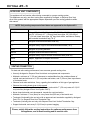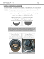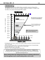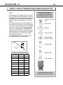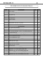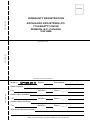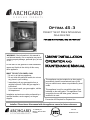
1
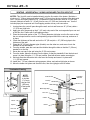
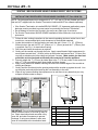
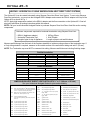
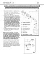
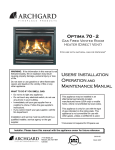
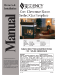
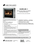
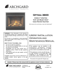
Optima 45 - 3
Direct Vent Free Standing
Gas Heater
For use with Natural Gas or Propane*
WARNING: If the information in this manual is
not followed exactly, fire or explosion may result
causing property damage, personal injury or loss
of life.
Do not store or use gasoline or other flammable
vapors and liquids in the vicinity of this or any
other appliance.
USERS’ INSTALLATION
OPERATION and
MAINTENANCE MANUAL
WHAT TO DO IF YOU SMELL GAS:
* Do not try to light any appliance.
* Do not touch any electrical switch; do not use
any phone in your building.
* Immediately call your gas supplier from a
neighbor’s phone. Follow the gas supplier’s
instructions.
* If you cannot reach your gas supplier, call the
fire department.
Installation and service must be performed by a
qualified installer, service agency or the gas
supplier.
This appliance may be installed in an after-market,
permanently located, manufactured home (USA
only) or mobile home, where not prohibited by local
codes.
This appliance is only for use with the type of gas
indicated on the rating plate. This appliance is not
convertible for use with other gases, unless a
certified kit is used.
*Conversion Kit Required for Propane Use
Installer: Please leave this manual with the appliance owner for future reference
7116 Beatty Dr
Mission, BC V2V 6B4
Canada
200-0169
FEBRUARY 2005
INTRODUCTION
Congratulations on choosing an Archgard fireplace!
The Optima 45-3 is one of the most advanced direct vent fireplace heaters available. It is
solidly designed using the latest technology and manufactured to the highest quality. It is our
aim to provide you with an appliance for many trouble-free years of reliable service.
The following are just some of the many features within your new gas fireplace:
Heater Classification
The Optima 45-3 is classified as a heating appliance. In
conjunction with an optional thermostat, the Optima 45-3 can
be operated continuously for zone heating.
High Efficiency
The Optima 45-3 has one of the highest efficiencies of any gas
fireplace, which means that it is less expensive to operate.
Adjustable Fan Speed
Heat circulation fan can be fully adjusted from high, medium or
low speeds to suit your comfort level.
Adjustable Flame
The flame aesthetics and heat output can be adjusted to suit
your heating needs.
Solid Construction
The Optima 45-3 is constructed mainly of 14 and 18 gauge
galvanized and aluminized steel for long life and durability.
Millivolt Control System
The gas control system is “thermostat-ready” for any optional
millivolt wall thermostat or wireless remote control.
Please read this manual carefully prior to installation and operation of the appliance.
Proper installation, operation and maintenance of the appliance will provide you with
many years of enjoyment.
We recommend you record the following information:
Fireplace Model Number
Fireplace Serial Number
Date of Installation
Type of Gas Used by the Fireplace
Dealer’s Name
TABLE OF CONTENTS
Caution and Safety Instructions
5
Appliance Certification / Installation Codes / Specifications / High Altitude Installation
6
Gas Connections
7
Appliance Dimensions / Description
8
Dimensions / Clearances / Alcove Installation
9
Locating Gas Heater / Vent Termination Locations
10
Allowable Termination Locations
11
Approved Vent Components / Venting Connection
12
Venting - Restrictor Placement
13
Venting Chart
14
Venting - Vertical Termination using Simpson Dura-Vent Pipe
15
Venting - Horizontally using Archgard Vent Kit (TVK-FSU)
17
Venting - Below Grade using Archgard Snorkel Kit (SNK-24)
18
Venting - Horizontally using Simpson Dura-Vent Direct Vent Systems
19
Log Placement
23
Optional Wall Switch or Thermostat
29
Final Installation Check / Initial Operation
30
First Fire and Lighting Instructions
31
Lighting Instructions on Rating Plate
32
Glass Door Removal / If your Glass Breaks
33
Troubleshooting Guide
34
Maintenance / Cleaning the Appliance
36
Servicing Under Warranty / Adjusting Primary Air
37
Changing Main Burner Orifice
38
Checking Inlet / Outlet Gas Pressure / Adjusting Pilot / Convertible Pilot Orifice
39
Replacing Convection Blower / Wiring Diagram
40
Valve Tray Assembly / Parts List
41
Parts List - Ceramic Logs & Burner Pan
42
Replacement Parts List
43
Archgard Warranty
44
Frequently Asked Questions
45
Notes
46
Warranty Registration Card
48
Optima 45 - 3
5
CAUTION
FOR YOUR SAFETY - Do not install or operate your Archgard Optima 45-3 Direct Vent Gas
Fireplace without reading and understanding this manual. Any installation or operational
deviation from this instruction manual voids the Archgard Industries Warranty and may prove
hazardous.
This appliance must be installed by a qualified gas installer and the installation must conform to
the installation codes.
Provide adequate clearance around air openings of the appliance.
Never obstruct front openings.
Provide adequate clearances for proper operation and servicing of the appliance.
This appliance must be properly connected to an approved venting system and must not be
connected to a chimney flue serving a separate solid fuel burning appliance.
SAFETY
Due to high temperatures, the appliance should be located out of traffic and away from furniture
and draperies.
Children and adults should be alerted to the hazards of high surface temperature and stay
away to avoid burns or clothing ignition.
Young children should be carefully supervised when they are in the same room as the
appliance.
Clothing or other flammable material should not be placed on or near the appliance.
Do not operate with cracked or broken glass. Be careful not to strike or slam the glass.
Any safety screen or guard removed for servicing an appliance must be replaced prior to
operating.
Installation and Repair should be done by a qualified service person. The appliance should be
inspected before use and at least annually by a professional service person. More frequent
cleaning may be required due to excessive lint from carpeting, bedding materials, et cetera. It is
imperative that the control compartments, burners and circulating air passageways of the
appliance are kept clean.
Optima 45 - 3
6
APPLIANCE CERTIFICATION
This appliance is tested and safety approved under the following US and Canadian gas
appliance standards:
- ANSI Z21.88b-2003 / CSA 2.33b-2003, Vented Gas Fireplace Heaters
- CAN/CGA-2.17-M91, Gas-Fired Appliances for Use at High Altitudes
Please contact Archgard Industries Ltd., if you have any questions regarding the certification of
this appliance.
INSTALLATION CODES
This appliance must be installed by a qualified gas appliance installer. The installation must
conform with the local codes or, in the absence of local codes, with the current National Fuel Gas
Code, ANSI Z223.1/ NFPA 54, in the US or Installation Code, CAN/CGA-B149, in Canada.
Electrical connections and grounding must conform with local code, or current National Electrical
code, ANSI/NFPA No. 70-1987, in the US and in Canada, the current Canadian Electrical Code,
CSA C22.1.
SPECIFICATIONS
Natural Gas (NG)
Manifold Pressure
Minimum Supply
Pressure for Purpose of
Input Adjustment
Propane (LP)
1.6 - 3.5 in. W.C. (0.4 - 0.9 kPa) 6.3 - 10.0 in. W.C. (1.6 - 2.5 kPa)
4.5 in. w.c. (1.2 kPa)
11.0 in. w.c. (2.8 kPa)
Nominal Input Rating
18,750 - 28,000 BTU/hr
(5.5 - 8.2 kW)
19,600 - 28,000 BTU/hr
(5.7 - 8.2 kW)
Orifice Size
#37 DMS (2.64 mm dia.)
#52 DMS (1.60 mm dia.)
0-4500 ft (0 - 1372 M)
0 - 4500 ft (0 - 1372 M)
3/16” (5 mm)
3/8” (9 mm)
Altitude
Primary Air Opening
HIGH ALTITUDE INSTALLATION
When installing this appliance beyond 4500 ft. (1372 M) above sea level, the appliance must
be properly de-rated and installed according to local codes, in the absence of local codes, with
the current National Fuel Gas Code, ANSI Z223.1/ NFPA 54, in the US or Installation Code,
CAN/CGA-B149, in Canada.
Optima 45 - 3
7
GAS CONNECTIONS
Before connecting the appliance to the gas supply line, double check that the appliance you
have purchased is designed for the gas type you are using. The gas type markings are located
on the certification label and also on the appliance’s gas valve.
Adequate clearance for proper installation and checking of the gas connections must be
provided. All gas connections must be checked for gas leaks.
Have your gas supplier or a qualified gas fitter run a gas supply line into the heater.
The line must be properly sized and fitted according to the installation codes. Immediately
upstream of the supply connection, the fitter shall provide an accessible manual shut-off valve
and a ⅛” (3 mm) NPT plugged tapping accessible for connection to a test gauge. When
connecting the supply line to the gas valve, the installer shall brace the gas valve to ensure that
gas valve is not moved from its bracket. If the valve is not braced when the supply line is
connected, the valve may be moved and cause a “break” in the main burner supply line. Such
damage is not covered by the manufacturer’s warranty.
CAUTION: The appliance and its individual shutoff valve must be disconnected from the gas
supply piping system during any pressure-testing of that system at test pressures in excess of ½
psig (3.5 kPa). The appliance must be isolated from the gas supply piping system by closing its
individual manual shutoff valve during any pressure-testing of the gas supply piping system at
test pressures equal to or less than ½ psig (3.5 kPa). Failure to do so will damage the appliance’s
gas valve. Such damage is not covered by the manufacturer’s warranty.
Natural Gas Pressure Settings:
The inlet supply or line pressure must be a minimum of 4.5” w.c. (1.1 kPa) and a maximum of 8”
w.c. (2 kPa). The orifice is a #37 DMS (2.66 mm) drill size.
ELEVATION
INPUT RATING
0-4500 ft (0-1372 M)
28,000 BTU/hr (8.2 kW)
4500 ft (1372 M) and above
28,000 BTU/hr (8.2 kW) less 4% per 1000 ft. (305 M)
Please contact your local utility company or distributor for the appropriate orifice size you require.
Propane Pressure Settings:
The inlet supply or line pressure must be a minimum of 11” w.c. (2.8 kPa) and a maximum of 14”
w.c. (3.5 kPa). The orifice is a #52 DMS (1.60 mm) drill size.
ELEVATION
INPUT RATING
0-4500 ft. (0-1372 M)
28,000 BTU/hr (8.8 kW)
4500 ft. (1372 M) and above.
28,000 BTU/hr (8.8 kW) less 4% per 1000 ft. (305 M)
Please contact your local utility company or distributor for the appropriate orifice size you require
NOTE: THE INPUT RATING SHOULD ALWAYS BE CHECKED WHEN FIRST RUNNING THIS
APPLIANCE. To do this, reduce the background flow rate, time the meter, light the fireplace and
take another reading after 15 minutes of operation. Check with your gas supplier for the gas BTU
content at your elevation. Input is the rate of flow multiplied by the heating value of the gas (cubic
feet/hour x BTU per cubic feet). Adjust the manifold pressure so that the unit does not operate
above the rated input.
Optima 45 - 3
8
APPLIANCE DIMENSIONS
B
C
A
DIMENSIONS
A
HEIGHT
30” (762 mm)
B
WIDTH
27” (685 mm)
C
DEPTH
17 ½” (444 mm)
APPLIANCE DESCRIPTION
UPPER LOUVERS
GLASS DOOR
LOWER LOUVERS
MAIN CONTROL PANEL
Optima 45 - 3
9
DIMENSIONS AND CLEARANCES
TOP VIEW
4” (101 mm)
BACKWALL
4” (101 mm)
11” (280 mm)
11” (280 mm)
4” (101 mm)
SIDEWALL
STRAIGHT INSTALLATION
CORNER INSTALLATION
ALCOVE INSTALLATION
SIDE VIEW
2” (50 mm) to top, 1” (25 mm) to
bottom and side surfaces of the vent
1” (25 mm) to the surface of the vent
24” (610 mm) minimum clearance
required from top of the appliance
to a combustible material
NOTE: The Optima 45-3 does
not require a non-combustible
hearth pad and can be installed
directly on the floor.
* Side
BACKWALL
4” (101 mm) minimum
clearance required
FLOOR
and back clearances for the alcove installation is the same as the straight and the corner installations
Optima 45 - 3
10
LOCATING GAS HEATER
This appliance must be installed in a location that is free of plumbing, electrical wiring and
heating or air conditioning ducts. Select a location that is accessible for venting.
See ALLOWABLE TERMINATION LOCATIONS listed in this manual.
NOTE: See venting chart for maximum and minimum vertical/horizontal venting configurations.
VENT TERMINATION LOCATIONS
1. See ALLOWABLE TERMINATION LOCATIONS and establish a suitable vent termination location.
2. In heavy snowfall areas make sure the vent termination is located where it can not be blocked by
snow and from snowfall or snow removal equipment.
3. Locate the vent termination away from plants, bushes or any other object near the vent termination
that will interfere or obstruct the air flow around it.
4. DO NOT recess vent termination into walls, sidings or planters.
5. Vent terminations located below 7ft (2.13 M) from grade level or anywhere that it can be a burn
hazard to the public, such as patios and balconies, must be protected with an approved termination
cage. If using Archgard Venting System order (Part # C-1).
*
*
*
*
*
3 feet (91 cm) within a
height 15 feet (4.5 m)
above the
meter/regulator assembly
C= Clearance to permanently
closed window
D= Vertical clearance to
ventilated soffit located
above the terminal within a
horizontal distance of 2 feet
(61 cm) from the center line
of the terminal
E= Clearance to unventilated soffit
F= Clearance to outside corner
G= Clearance to inside corner
H= Clearance to each side of
center line extended above
meter/regulator assembly
3 feet (91 cm)
12 inches (30 cm)
B= Clearance to window or
door that may be opened
L= Clearance to service
regulator vent outlet
12 inches (30 cm)
A= Clearance above grade,
veranda, porch, deck, or
balcony
Canadian Installations (1)
*
*
*
*
*
*
*
12 inches (30 cm)
12 inches (30 cm)
US Installations (2)
*
*
3 feet (91 cm) above if
within 10 feet (3 m) horizontally
9 inches (23 cm)
In accordance with the current ANSI Z223.1/NFPA 54, National Fuel Gas Code
In accordance with the current CSA B149.1, National Gas and Propane Installation
Code
12 inches (30 cm) ++
7 feet (2.13 m) +
6 feet (1.83 m)
12 inches (30 cm)
US Installations (2)
(*) For clearances not specified in ANSI Z223.1/NFPA 54 or CSA B149.1, “Clearances shall
be in accordance with local installation codes and the requirements of the gas supplier.”
(++) Permitted only if veranda, porch, deck, or balcony is fully open on a minimum of two
sides beneath the floor.
(+) A vent shall not terminate directly above a side walk or paved driveway that is located
between two single family dwellings and serves both dwellings
(2)
(1)
M= Clearance under veranda,
porch, deck, or balcony
L= Clearance above paved
sidewalk or paved driveway
located on public property
K= Clearance to a mechanical
air supply inlet
J= Clearance to non-mechanical air
supply inlet to building or the
combustion air inlet o any other
appliance
Canadian Installations (1)
Optima 45 - 3
11
ALLOWABLE TERMINATION LOCATIONS
Optima 45 - 3
12
APPROVED VENT COMPONENTS
The appliance will not function without being connected to a proper venting system.
This appliance may only use direct vent system supplied by Archgard, or Simpson Dura-Vent
direct vent systems with the appropriate Adaptor dependent upon the venting guidelines within
this manual.
NOTE: Only venting components listed below are approved for the Optima 45-3
PART #
DESCRIPTION
TVK-FSU
Archgard Top Vent Kit. Kit includes 9 ft (2.74 M) of 4” (101 mm) gas flex
liner, 36” (914 mm) of 7” (178 mm) black stove pipe, 24” (610 mm) of
7” (914 mm) black stove pipe, 90o deg. black elbow, wall sleeve, firestop
and horizontal termination cap (TK-1)
TK-1
Archgard Horizontal termination head only
C-1
Archgard Safety Cage for Horizontal termination head (TK-1)
VSD-1
Archgard Vinyl siding deflector
SNK-24
Archgard Snorkel termination head only
C-2
Archgard Safety Cage for Snorkel termination head (SNK-24)
SDA-U
Adapter, Appliance to Simpson Dura-Vent
DV-GS
Simpson Dura-Vent venting system
VENTING CONNECTION
For best and safe venting performance, here are some general venting rules:
• Use only Archgard or Simpson Dura-Vent direct vent systems and components.
• Maintain a minimum of 1” (25 mm) clearance to combustibles from the outside surfaces of
vertical vents and minimum of 1” (25 mm) sides and bottom, and 2” (50 mm) from top surfaces
of horizontal vents.
• Observe local code restrictions, if any, regarding the installation of this type of gas appliance.
• Observe the venting charts given in this manual
• Use vent spacers between the inside 4” (101 mm) and outside 7” (178 mm) vents at 3 ft (915
mm) intervals (Archgard Direct Vent System ONLY).
• Never slope horizontal vents downwards, towards the vent termination.
• Maintain a minimum ¼” rise (6mm) for every linear foot (305 mm) of horizontal vent.
• Terminate (Horizontally) the vent only with an approved vent termination supplied by Archgard
Part # TK-1 or Simpson Dura-Vent Termination Cap.
• Terminate (Vertically) the vent only with Simpson Dura-Vent Vertical Termination Cap.
• Support horizontal vents every 3 ft (915 mm) to prevent sagging.
Please, strictly follow the venting instructions for optimum performance from
the appliance, and to avoid sooting and/or service calls.
Optima 45 - 3
13
VENTING - RESTRICTOR PLACEMENT
RESTRICTOR PLACEMENT FOR SIDEWALL VENTED APPLICATIONS ONLY
WARNING: These restrictors are only to be installed in the vent system if the vent exceeds 10’ in
vertical height. See below which restrictor to use.
Installing them under any other circumstances may cause hazardous venting
conditions and may result in personal injury, property damage or death.
NOT FOR USE IN VERTICALLY VENTED APPLICATIONS
Restrictor Number #1
Sidewall Venting - Above
Ten Feet (10’)
Restrictor Number #2
Sidewall Venting - Above
Eighteen Feet (18’)
NOTE: Vent restrictors are designed to reduce vertical stack action for vent
terminations which will reduce the velocity of incoming combustion air and
not adversely affect the standing pilot or the efficiency of the appliance.
Simpson Dura-Vent
With Simpson Dura-Vent,
locate the restrictor in the exhaust
section fitting into the formed lip.
Archgard System
In the Archgard system, the
restrictors are placed on the
exhaust outlet on the appliance.
Simpson Dura-Vent
Archgard System
Optima 45 - 3
14
VENTING CHART
The appliance will not function without being connected to a proper venting system.
This appliance may only use direct vent system supplied by Archgard, or Simpson DuraVent direct vent systems with Archgard SDK-3 adapter.
7.93 M
7.32 M
V
E
R
T
I
C
A
L
H
E
I
G
H
T
No restrictors are to be used
in vertical vent installations.
6.71 M
6.10 M
Sidewall installation only
5.49 M
4.88 M
4.27 M
Note: No Installations are
permitted outside of this
range.
Sidewall
installation only
3.66 M
3.05 M
Note: See instructions on page
13 for restrictor placement.
2.44 M
1.83 M
1.22 M
610 mm
610
mm
1.22 1.83 2.44 3.05
3.66
Meters
Feet
• A minimum of 3’ (914 mm) of vertical vent to center of elbow is required for a maximum horizontal
•
•
•
•
run of 3’ (914 mm).
Chart is for one 90° bend, with ¼” (7 mm) vertical raise minimum per foot of horizontal length.
For each additional 90° or two 45°, add one foot of vertical height.
Maximum three 90º bends, or equivalent.
Minimum 2 ft (610 mm) straight length between bends.
VENTING ABOVE ROOF OF THE HOUSE USING A VERTICAL TERMINATION
Use Simpson Dura-Vent listed direct vent system caps for all vertical vent termination
applications (through the roof).
Please strictly follow the venting instructions for optimum performance
from the appliance and to avoid sooting and/or service calls.
Optima 45 - 3
15
VENTING - VERTICAL TERMINATION USING SIMPSON DURA-VENT PIPE
The Optima 45-3 can be vented vertically using Simpson Dura-Vent Direct Vent System. To
vent using Simpson Dura-Vent exclusively, you must use the Archgard SDA-U Adaptor and
connect the (SDA-U) adaptor to the top of flue outlet on the Optima 45-3 gas fireplace.
1. Maintain 1” (25 mm) clearance (air space) to combustibles when passing through ceilings
walls, roof, enclosures, attic rafter, or other nearby combustible surfaces. Do not pack air
spaces with insulation. Check page 14 (Venting Chart) for the maximum vertical rise of the
venting system.
2. Set the gas appliance in its desired location. Drop a plum bob down from the ceiling to the
position of the appliance flue exit, and mark the location where the vent will penetrate the
ceiling. Drill a small hole at this point. Next, drop a plumb bob from the roof to the hole previously drilled in the ceiling, and mark the spot where the vent will penetrate the roof.
NOTE: you may wish to relocate the appliance to avoid cutting load-bearing members.
3. A Firestop spacer must be installed in the floor or ceiling of every level. To install the
Firestop spacer in a flat ceiling cut a 10” (254 mm) square hole. Frame the hole as shown
Fig. 1 and install the firestop.
4. Assemble the desired lengths of pipe and elbows as outlined in the Venting Chart, necessary to reach from the Appliance adaptor (SDA-U), if using Simpson Dura-Vent from the appliance up through the roof. Ensure that all Simpson Dura-Vent and/or flexible is connected
and sealed accordingly.
5. Cut a hole in the roof centered on the small drill hole placed in the roof as outlined in Step 2.
6. The hole should be of sufficient size to meet the minimum requirements for each combustibles of 1” (25 mm). Slip the flashing under the shingles (shingles should overlap half of the
flashing) as per Fig.2.
7. Continue to assemble pipe lengths and/or flexible gas venting.
8. Ensure vent is vertical and secure the base of the flashing to the roof with roofing nails,
slide storm collar over the section and seal with a mastic.
9. Install the vertical termination cap by twist-locking it.
NOTE: Apply high temperature sealant to inner and outer pipe on every Simpson Dura-Vent
twist-lock joint. See Fig. 3
Female
Locking Lugs
10” (254mm)
square hole
framing
Male
Locking Lugs
firestop
spacer
Fig. 1
Sealant
Fig. 2
Fig. 3
Optima 45 - 3
16
VENTING - VERTICAL TERMINATION USING SIMPSON DURA-VENT PIPE
NOTE:
• Galvanized pipe is desirable above the roofline
due to its higher corrosion resistance. Continue
to add pipe sections throughout the flashing until
the height of the vent cap meets the minimum
height requirements specified in Fig. 5 or local
codes.
• For steep roof pitches, the vertical height must
be increased. A poor draft, or down drafting can
result in high wind conditions, trees or neighbor's
roof lines. In these cases increasing the height
may solve a drafting problem. REMEMBER to
check that you are within the maximum vertical
height restrictions, and are placing the appropriate vent restrictors as outlined in the venting
chart within this manual.
• Any storage spaces or closets which the vent
must pass through must be enclosed.
Typical Vertical venting
configuration using Simpson
Dura-Vent Direct Vent System
Vertical Termination
Cap
Storm Collar
Flashing
Ceiling Firestop
Round Support
Box/wall Thimble
Length of Pipe
H
H-represents vent
height
Fig. 5
Roof Pitch
Minimum Vent Height
Flat to 7/12
2 Feet
0.61 Meters
Over 7/12-8/12
2 Feet
0.61 Meters
Over 8/12-9/12
2 feet
0.61 Meters
Over 9/12-10/12
2.5 Feet
0.76 Meters
Over 10/12-11/12
3.25 Feet
1.00 Meters
Over 11/12-12/12
4 Feet
1.22 Meters
Over 12/12-14/12
5 Feet
1.52 Meters
Over 14/12-16/12
6 Feet
1.83 Meters
Over 16/12-18/12
7 Feet
2.13 Meters
Over 18/12-20/12
7.5 Feet
2.29 Meters
Over 20/12-21/12
8 Feet
2.44 Meters
Length of Pipe
SDA-U adaptor
Simpson Dura-Vent venting
components are listed on page 21
Optima 45 - 3
17
VENTING - HORIZONTALLY USING ARCHGARD TVK-FSU VENT KIT
NOTES: This Vent Kit must be installed directly onto the flue outlet of the heater. Maintain a
minimum of 1” (25mm) sides and bottom, and 2” (50 mm) from the top surfaces of the horizontal
vent. Use the vent spring spacers (Fig. 1) between the inner and outer vents at 3 ft (900 mm)
intervals. Maintain at least a ¼ “ (6 mm) rise for every 12” (305 mm) horizontal vent. Use the
included pipe joint compound and 3 self tapping screws at every vent connection.
1. Locate where the vent will pass though the wall, and cut and frame an 10” (25 mm) wide x
11” (279 mm) high hole.
2. Apply pipe joint compound on the 4” (101 mm) crimp end of the vent cap and slip on one end
of the flex vent. Fasten with 3 self-tapping screws.
3. Place the horizontal section of the 7” (179 mm) diameter rigid pipe over the flex vent so that
the non-crimped end fits over the corresponding crimped end on the vent cap, and screw it
in place.
4. Check the thickness of the wall and cut the 10” (25 mm) dia. x 12” (305 mm) pipe to the
thickness of the wall.
5. Place the 10” (25 mm) diameter pipe (thimble) over the other two, and screw it onto the
standoffs of the termination.
6. From the outside, pass the vents and the thimble through the hole so that the 2” (50 mm)
standoff is on the top.
7. Screw the vent cap to the wall using the 2” (50 mm) screws.
8. From the inside, place the firestop over the pipes, so that the standoffs fit into the hole and
screw it in place using the 1 ¼” (32 mm) screws. Seal with silicone sealer around pipe.
9. Similarly place the decorative trim collar over the firestop and screw it in place with
1 ¼“ (32 mm) screws.
10. Install the 1” (25 mm) diameter spring spacers, elbow, and vertical rigid pipe as shown.
11. Move the heater into place and screw the flex, then the rigid pipe onto its collars.
Termination Framing
11” (279 mm)
10”
(254 mm)
NOTE:
Be sure
to include
¼” (6 mm)
rise per foot
(305 mm)
of horizontal
length.
Wall Thimble
Insulation
Standoff
Firestop
90° elbow
Black Rigid Pipe
Vent cap
Spring spacer
Flex vent
Fig. 1
Spring Spacers
Collars
Interior wall
Elbow
Spacer
Flex vent
Rigid pipe
Heater
Outside wall
Optima 45 - 3
18
VENTING - BELOW GRADE USING FLEXIBLE DIRECT VENT SYSTEMS
INSTALLATION PROCEDURES FOR ARCHGARD SNORKEL KIT (Part # SNK-24)
NOTE: The Archgard Snorkel kit is designed for 4” x 7” (101 mm x 178 mm) flexible gas liners
that are NOT supplied with the Snorkel Termination Head and MUST be ordered separately.
• If the Snorkel Termination is installed BELOW GRADE, (I.E. basement application) proper
drainage must be provided to prevent water from entering the Snorkel Termination.
• Do not attempt to enclose the Snorkel in the wall or any other type of enclosure.
• For Snorkel Terminations ABOVE GRADE installations follow national or local code re-
quirements.
1. Follow all other venting instructions in the manual regarding minimum vertical rise to horizontal runs, recommended pitch, and clearances to combustible materials.
2. Locate the centerline of the termination and mark the wall. Cut an 11” x 10” (279mm x
254mm) hole in the wall. NOTE: a 2” (50mm) x 1 ½” (13mm) around the 7” (178mm) liner
is required. See Fig. 1 for termination framing.
3. Drill holes and insert the anchors as required.
4. Gently pull the coaxial vent through the hole. Apply a small bead of high temperature furnace cement around the 4” (101mm) collar on the snorkel and secure the 4” (101mm) flex
vent with a stainless steel hose clamp and at least 3 screws. Make certain you have not
pulled the vent too hard and accidentally disconnected it from the appliance.
5. Securely attach the 7” (178 mm) air intake pipe to the 7” (178 mm) collar on the snorkel kit
with a 7” (178 mm) stainless steel hose clamp and three screws.
6. Apply a thick bead of all weather caulking all around the outside edges of the snorkel assembly and flanges.
7. Gently feed the vent back into the opening and push the snorkel up against the wall. Line
up the holes previously drilled and lag the vent assembly to the wall.
8. Wipe off any excess caulking that squeezes out or add more to any areas that you may
suspect will allow water to seep in.
A
BELOW GRADE
Snorkel
ABOVE GRADE
Snorkel
B
C
Adequate
Drainage
D
F
E
IMPORTANT: Do not locate termination head
where excessive snow or ice build up may occur. Check termination head area after every
snow fall, and clear if necessary to prevent
blockage. If using snow blowers, make sure
snow is not directed at the termination head.
Description
Size
A
Total Protrusion
13 ½” (343 mm)
B
Mounting Flange
34 ½” (877 mm)
C
Finished Body
33” (838 mm)
D
Mounting Flange
10 ½” (267 mm)
E
Finished Body
9” (228 mm)
F
From Body to start of
exhaust vent
1 ¼” (31 mm)
Optima 45 - 3
19
VENTING - HORIZONTALLY USING SIMPSON DURA-VENT DIRECT VENT SYSTEMS
The Optima 45-3 can be vented horizontally using Simpson Dura-Vent Direct Vent System. To vent using Simpson
Dura-Vent exclusively, you must use the Archgard SDA-U Adaptor and connect the SDA-U adaptor to the top of the
Optima 45-3 as shown in Fig. 1.
NOTE: Apply high temperature sealant to the SDA-U adaptor and the flue connection on the Optima 45-3. Seal all
pipe joints and follow all venting instructions within this manual.
NOTE: Call your local Authorized Archgard Dealer to purchase Simpson Dura-Vent Direct Vent Kits and/or venting
components.
Minimum components required for horizontal termination using Simpson Dura-Vent:
1 SDA-U (Appliance adaptor)
1 Horizontal Termination Cap
1 Length of pipe for top of appliance
1 90 Deg. Elbow
1 Wall Thimble
1 Length of pipe to suit wall thickness
Measure wall thickness from the back of the fireplace standoffs to inside mounting surface of the termination cap. If
a Vinyl siding standoff is required, measure to the outside surface of the wall without siding and add 2” (50 mm).
NOTE: The Termination cap must NOT be recessed into siding. Measure wall thickness including finishing straps.
Flat Wall Installation
Wall Thickness (inches)
Vent Length Required (inches)
Wall Thickness (mm)
Vent Length Required (mm)
4” - 5 ½”
6”
101 mm - 140 mm
152 mm
228 mm
7” - 8 ½”
9”
178 mm - 216 mm
10” - 11 ½”
12”
254 mm - 292 mm
305 mm
9” - 14 ½”
11” - 14 ⅝” Adj. Pipe
228 mm - 368 mm
228 mm - 371 mm
15” - 23 ½”
17” - 24” Adj. Pipe
381 mm - 597 mm
432 mm - 610 mm
Wall Thickness (inches)
Vent Length Required (inches)
Corner Installations
Wall Thickness (mm)
Vent Length Required (mm)
228 mm - 371 mm
3 ¼” - 6 ¾”
11” - 14 ⅝” Adj. Pipe
82 mm - 171 mm
7 ¾” - 16 ¼”
17” - 24” Adj. Pipe.
197 mm - 412 mm
432 mm - 610 mm
7 ¼” - 8 ¾”
6” + 12”
Or 9” + 9”
184 mm - 222 mm
101 mm + 305 mm
Or 228 mm + 228 mm
4 ¼” - 5 ¾”
6” + 9”
108 mm - 146 mm
152 mm - 228 mm
SIMPSON DURA-VENT DIRECT VENT PARTS LIST 6 ⅝” x 4” (168 mm x 101 mm)
See your Authorized Archgard Dealer for price and availability.
Part #
971
970
987
Description
0
Horiz. Term. Kit Includes; 90 . Blk elbow, wall thimble
cover, Horiz. square term. Cap, 24” (610 mm) blk pipe
and 11”-14” (279 mm x 356 mm) adj. blk pipe.
Basic Horiz. Term. Kit Includes; 900. blk elbow, wall
thimble cover, Horiz. square term. cap.
Vertical Termination Kit Includes;
0/12- 6/12 pitch adj. flashing, storm collar, low profile
term. cap.
Part #
Description
984
Horizontal (Square) Termination Cap
902B
48” (1.22 M) Pipe Length - Black
985
Horiz. (SQ) Term. Cap. High Wind.
911B
11” - 14 ⅝” (228 mm x 371 mm) Adj. Pipe
Length - Black
982
Snorkel - 14” (356 mm) Rise Term. Cap
981
Snorkel - 36” (914 mm) Rise Term. Cap
940
Wall Thimble - Support Box
917B
17”’ - 24” (432 mm) x (610mm) Adj. Pipe
Length - Black
945
450 Elbow - Galv.
945B
450 Elbow - Black
6” (152 mm) Pipe Length - Black
945G
450 Elbow - Swivel - Galv.
907B
9” (228 mm) Pipe Length - Black
945BG
450 Elbow - Swivel - Black
906
12” (305 mm) Pipe Length - Galv.
990
900 Elbow - Galv.
906B
12” (305 mm) Pipe Length - Black
990B
900 Elbow - Black
904
24” (610 mm) Pipe Length - Galv.
990G
900 Elbow - Swivel - Galv.
24” (610 mm) Pipe Length - Black
Description
48” (1.22 M) Pipe Length - Galv.
908B
904B
Part #
902
990BG
941
Cathedral/Ceiling - Support Box
3951
Brass Trim for Wall Thimble/Ceiling Sup.
963
Firestop Spacer
943
Flashing 0/12 - 6/12
943S
Flashing 7/12 - 12/12
953
Storm Collar
90 Elbow - Swivel - Black
950
Vinyl Siding Standoff
Wall Strap
Wall Thimble
0
903
36” (914 mm) Pipe Length - Galv.
991
Vertical Termination Cap High Wind
988
903B
36” (914 mm) Pipe Length - Black
980
Vertical Termination Cap
942
Optima 45 - 3
20
VENTING - HORIZONTALLY USING SIMPSON DURA-VENT DIRECT VENT SYSTEMS
INSTALLATION PROCEDURES FOR SIMPSON DURA-VENT DIRECT VENT SYSTEM
1. Set the Optima 45-3 in its desired location.
Determine if wall studs or roof rafters are in
the way the when venting system is attached. You may want to adjust the location
of the unit to compensate.
2. Simpson Dura-Vent Venting System is designed with special twist-lock connections to
connect to the appliance. An Archgard adaptor (SDA-U) is required. The adaptor will allow Simpson Dura-Vent System to be used.
3. Apply a bead of silicone inside the outer section of the SDA-U adaptor (crimped side).
Slip the adaptor over the existing inner and
outer flue collar and fasten it to the outer collar only with 3 screws (drill pilot holes first).
Level the appliance and fasten it to the framing using nails or screws through the nailing
strips.
4. Assemble the desired combination of pipe
and elbows to the appliance adaptor and
twist lock the pipe.
Fig. 1
Refer to Venting Chart on Page 16
#1
#2
#3
#4
#5
#6
#1 Vertical Termination
#2 Vinyl Siding Standoff
(Optional)
#7
#3 Wall Thimble
#8
#4 Round Support Box
#5 Adj. Length of pipe
#6 900 Elbow
NOTE: Twist-lock procedure: Four indentations, located on the female ends of the pipes
and fittings, are designed to slide straight onto
the male ends of adjacent pipes and fittings by
orientating the four pipe indentations so they
match and slide in to the four entry slots on the
male ends (Fig. 2). Push the pipe sections
completely together, then twist-lock one section clockwise approximately one quarter turn,
until the two sections are fully locked. The female locking lugs will not be visible from the
outside, on the pipe or fittings. They may be
located by examining the inside of the female
ends. Horizontal vent runs MUST be supported
every three feet (76 mm). Wall straps are available for this purpose.
#7 Pipe Length
#8 SDA-U Adaptor 3” (76mm)
Female
Locking
Lugs
Male
Locking
Lugs
Sealant
Fig. 2
Optima 45 - 3
21
VENTING - HORIZONTALLY USING SIMPSON DURA-VENT DIRECT VENT SYSTEMS
INSTALLATION PROCEDURES FOR SIMPSON DURA-VENT DIRECT VENT SYSTEM
5. Mark the wall with an 11” (279 mm) x 10” (254 mm) hole.
See termination framing on page 22. The center of the hole
should line up with the centerline of the horizontal pipe. Cut
and frame the 11” (279 mm) x 10” (254 mm) hole in the exterior wall where the vent will be terminated. If the wall being penetrated is constructed of non-combustible material,
(I.E. a masonry block, or concrete) a hole with zero clearance is acceptable. NOTE: The horizontal run of vent must
be level, or have a ¼” (6 mm) rise for every 12” (305 mm) of
run towards the termination. Never allow the vent to run
downward. This could cause high temperatures and may
present the possibility of a fire. ALSO: The location of the
horizontal vent termination on an exterior wall must meet
local and national building codes, and must not be blocked
or obstructed. For Allowable Termination Locations see
page 11 in this manual.
Fig. 1
Fig. 2
6. Position the Horizontal Vent Termination in the center of the
square hole (arrow on the vent cap should be facing UP),
and run a bead of non-hardening sealant around the outside
edges of the termination, so as to make a seal between the
termination and the wall. Finish attaching the termination
cap to the wall with the four wood screws provided with the
termination cap. NOTE: The four wood screws provided
should be replaced with the appropriate fasteners for
stucco, brick, concrete or other types of siding. For buildings
with VINYL SIDING, a Vinyl Siding Standoff should be installed between the vent cap and the exterior wall. Attach
the Vinyl Siding Standoff to the Horizontal Termination Cap
by bolting the flat portion of the Vinyl Siding Standoff (Fig.1)
so that an air space will exist between the wall and the Vent
Termination.
7. Locate and slide the Wall Thimble Cover over the vent pipe.
8. Slide the appliance and vent assembly towards the wall,
carefully inserting the vent pipe into the vent cap assembly.
It is important that the vent pipe extend into the vent cap
sufficient distance so as to result in a minimum pipe overlap
of 1 ¼” (31 mm). Secure the connection between the vent
pipe and the vent cap by attaching the two sheet metal
strips extending from the vent cap assembly into the outer
all of the vent pipe. Use the two sheet metal screws provided to connect the strips to the pipe section. Bend any remaining portion of the sheet metal strip back towards the
vent cap, so it will be concealed by the Wall Thimble Cover.
(Fig. 2)
9. Slide the Wall Thimble Cover up to the wall surface and attach to the wall with wood screws. (Fig. 3)
Fig. 3
Optima 45 - 3
22
VENTING - BELOW GRADE USING SIMPSON DURA-VENT DIRECT VENT SYSTEMS
INSTALLATION PROCEDURES FOR SIMPSON DURA-VENT DIRECT VENT SYSTEM
SNORKEL TERMINATIONS: For installations requiring a vertical rise on the exterior of the
building, 14” (355mm) and a 36” (914mm) tall Snorkel Termination Caps are available.
Follow the same installation procedures as used for Horizontal Termination.
NEVER install the snorkel upside down. IMPORTANT: Proper drainage must be provided to
prevent water from entering the Snorkel Termination Cap.
NOTES:
• If the Snorkel Termination is installed BELOW GRADE, IE basement application, proper
drainage must be provided to prevent water from entering the Snorkel Termination.
• Do not attempt to enclose the Snorkel in the wall or any other type of enclosure.
• For Snorkel Terminations ABOVE GRADE installations follow national or local code re-
quirements.
BELOW GRADE
ABOVE GRADE
Snorkel
Adequate
Drainage
Snorkel
Optima 45 - 3
23
LOG PLACEMENT
Archgard chooses ceramic fiber logs for use in the Optima 45-3. The logs are designed to give a
realistic fire package, and are created for long life, to give you the same beautiful look as the day
they were originally installed. Care must be given when first installing the logs and if removed for
servicing, as they can be damaged or broken if not handled properly. Please note that logs may
vary slightly in size and shape but does not affect performance.
Gas and vent connection must be made before installing the ceramic fiber logs on the burner.
NOTE: Improper placement of logs may cause sooting on the internal parts and glass, and will not
be covered under warranty. Do not use broken or damaged logs.
WARNING: Failure to position the parts in accordance with these diagrams or failure to use
only parts specifically approved with this appliance may result in property damage
or personal injury.
LOG #83
LOG #142
LOG #12
LOG #80
LOG #74
LOG #13
PLATINUM EMBERS
NOTE: Installing the ceramic logs in any other position other than shown will result in flame impingement
causing sooting of the logs, brick liner and ceramic glass viewing area.
Optima 45 - 3
24
LOG PLACEMENT - Continued
OPTIMA 45-3
7-PIECE LOG SET SHOWN BELOW
The bottom of each log will be stamped with a 2- or 3-digit code.
The following pages will identify each log and the correct log position.
LOG #80
LOG #12
LOG #142
LOG #74
LOG #83
LOG #13
Burner Pan & Pin Locations
Optima 45 - 3
25
LOG PLACEMENT - Continued
STEP 1 - Locate Log # 12 and place it on the burner pins as shown.
LOG #12
STEP 2 - Locate Log #80 and place it on the burner pins as shown.
LOG #80
Optima 45 - 3
26
LOG PLACEMENT - Continued
STEP 3 - Locate Log #142 and place it on Log #12 as shown.
LOG #142
LOG #12
STEP 4 - Locate Log #13 and place it as shown, aligning holes & pins on logs and burner.
LOG #13
Optima 45 - 3
27
LOG PLACEMENT - Continued
STEP 5 - Locate Log #83 and place it as shown. The bottom left of the log should be in the burner hole.
LOG #83
STEP 6 - Locate Log #74 and place it as shown. The log will rest on burner pin.
LOG #74
Optima 45 - 3
28
LOG PLACEMENT - Continued
FRONT VIEW
CERAMIC BRICK PANELS
The Optima 45-3 comes with a set of Ceramic Brick Panels. They are factory-installed for your convenience,
therefore no adjustments should be made. If you find any damage to the Ceramic Brick Panels please contact
your Authorized Archgard Dealer to order replacements.
Optima 45 - 3
29
OPTIONAL WALL SWITCH OR THERMOSTAT
If a wall-mounted switch or a wall-mounted thermostat is desired, Archgard recommends that
the device be wired as shown in Fig 1.
Note: Archgard Industries does not manufacture or sell any wall switch or wall thermostat and
will not extend warranty to them.
Thermostat / wall switch wire table
Recommended Maximum Lead Length for two wires
Wire Size
Max. Length
14 GA.
50 Ft. (15.24 M)
16 GA.
32 Ft. (9.75 M)
18 GA.
20 Ft. (6.09 M)
20 GA.
12 Ft. (3.65 M)
22 GA.
9 Ft. (2.74 M)
VALVE CONNECTION FOR MILLIVOLT VALVE
Fig. 1
C
B
D
PILOT ASSEMBLY
A
ELECTRODE
B
THERMOPILE
C
PILOT CAP
D
THERMOCOUPLE
A
WIRE TO
PIEZO
(SPARKER)
PILOT SUPPLY TUBE
THERMOCOUPLE LEAD
OPTIONAL
WALL
SWITCH, WALL
THERMOSTAT
OR REMOTE
CONTROL
ON / OFF SWITCH
Optima 45 - 3
30
FINAL INSTALLATION CHECK
Each Archgard Gas Fireplace is checked and tested at the factory prior to being packaged and
shipped to our dealers and finally installed in your home. Archgard recommends that before
leaving this unit with the customer, the installer must ensure that the appliance is firing
correctly, and that the electrical system is in working order. This will include:
1. Perform Leak tests of supply line, gas control valve, supply line from gas control valve and
pilot assembly.
2. Clocking the appliance to ensure the correct firing rate (see rating plate or page 6 of this
manual).
3. If required, adjusting the primary air to burner to ensure that the flame does not carbon or
soot. (see rating plate or page 6 of this manual) .
4. Check for proper operation including correct drafting.
5. The FAN system should be turned ON for a minimum of 15 minutes to ensure the fan, rheostat and fan sensor are all working correctly. After the system has been checked, and confirmed that the fan components are in working order, turn the fan system OFF and refer to
the instructions for FIRST FIRE located in this manual.
As a reminder, a TAG is attached to all of our gas fireplaces. This TAG is located at the gas
control valve. (See Fig 1).
Fig. 1
ARCHGARD INDUSTRIES LTD.
*** INSTALLER ***
IMPORTANT NOTICE
ALL GAS AND ELECTRICAL CONNECTIONS
** MUST ** BE CHECKED AND TESTED AT
TIME OF INSTALLATION.
Any alteration to the product that causes carboning or sooting that results in any
damage or requires cleaning is not the responsibility of the manufacturer.
INITIAL OPERATION
1. Check that the appliance is properly vented and connected to the gas supply.
2. Check that the logs and branches are properly placed.
3. Check that all external parts, such as grills, door and faceplate are properly attached and
fastened.
4. Do not operate this appliance with broken or cracked glass doors or without the door (s) in
its correct (and latched) position. Do not use abuse the glass by either striking or slamming
shut.
5. Check that there are no fingerprints left on gold surfaces or glass panels, as high
temperatures can bake these prints permanently.
Optima 45 - 3
31
FIRST FIRE
When operated for the first few times, the appliance will emit some odor and fumes. This is due
to the heat from the appliance evaporating the oils and solvents used in fabricating the
appliance. Close off the room to the rest of the house and open all windows. Keep the room
well ventilated as smoke alarm may sound. Run the appliance for at least 6 hours at maximum
setting with blower set to “OFF” to allow paint to cure (after the installer has checked to ensure
the fan is operational). Smoke and fumes caused by the curing process may cause discomfort
to some individuals.
LIGHTING INSTRUCTIONS - CAUTION
WARNING : If you do not follow these instructions exactly, a fire or explosion may
result, causing property damage, personal injury or loss of life. Do not
operate the appliance with the glass front removed, cracked or broken.
Replacement of broken glass should be done by a licensed or qualified
service person.
This appliance has a pilot which must be ignited using the sparker located next to the appliance
valve controls. When lighting the pilot, follow the start-up procedures EXACTLY. See next page
or rating plate for complete lighting instructions.
1.
2.
3.
4.
BEFORE LIGHTING, smell all around the appliance area for gas. Be sure to smell next to
the floor, because some gases are heavier than air and will settle on the floor.
IF YOU SMELL GAS, follow the instructions on the front cover of this manual.
Use only your hand to push in or turn the gas control knob. Never use tools. If the knob
will not push in or turn by hand, do not try to repair it. Call a qualified service technician.
Force or attempted repair of gas control knob may result in a fire or explosion.
Do not use this appliance if any part has been under water. Immediately call a qualified
service technician to inspect the appliance and to replace any part of the control system
and any gas control which has been under water.
Optima 45 - 3
32
LIGHTING INSTRUCTIONS ON RATING PLATE
FOR YOUR SAFETY READ BEFORE
WARNING: If you do not follow these instructions exactly, a fire of explosion may result causing
property damage, personal injury or loss of life.
A. This appliance has a pilot which must be lighted by a spark
ignitor. When lighting the pilot follow these instructions
exactly.
• If you cannot reach your gas supplier, call the fire
department.
C. Use only your hand to push in or turn the gas control knob.
Never use tools. If the knob will not push in or turn by hand
don’t try to repair it, call a qualified service technician.
Forced or attempted repair may result in a fire or
explosion.
B. BEFORE LIGHTING smell all around the appliance area
for gas. Be sure to smell next to the floor because some
gas is heavier than air and will settle on the floor.
WHAT TO DO IF YOU SMELL GAS
• Do not try to light any appliance.
D. Do not use this appliance if any part has been under water.
• Do not touch any electrical switch; do not use any phone in
Immediately call a qualified service technician to inspect
your building.
the appliance and to replace any part of the control system
• Immediately call your gas supplier from a neighbor’s
and any gas control which has been under water.
phone. Follow the gas supplier’s instructions.
LIGHTING INSTRUCTIONS
1. STOP! Read the safety information above on this label.
depressed for approximately 30 seconds. Release knob. If
pilot should go out, repeat steps 3 to 5.
• If the knob does not pop up when released, stop and
immediately call your service technician or gas supplier.
• If the pilot will not stay lit after serveral tries, turn the gas
control knob to “OFF” and call your service technician or
gas supplier.
2. Set the remote switch to “OFF”. Set the thermostat to the
lowest setting. (Only if your appliance is equipped with
these devices.)
3. Turn off all electric power to the appliance.
4. Open lower louvers or access door.
7. If the appliance has a manual valve, turn gas control knob
counterclockwise 4 to the desired heat setting from “LO”
to “HI”. If the appliance has an automatic valve, turn gas
control knob counterclockwise 4 to “ON” and set the flame
adjustment knob to the desired heat setting from “LO” to
“HI”.
3. Press slightly and turn the control knob clockwise 3 to the
“OFF” position.
4. Wait 5 minutes to clear out any gas. Then smell for gas,
including near the floor. If you smell gas, STOP! and follow
instruction “B” above.
8. Set the remote switch to “ON”. Set the thermostat to the
desired setting. (Only if your appliance is equipped with
these devices.)
5. Find pilot. It is located between the logs near the center
behind the burner.
6. Press slightly and turn control knob counterclockwise 4 to
“PILOT”. Depress knob and light pilot by repeatedly
pressing the sparker. Once flame is established, hold knob
Flame Adjustment Knob
9. Turn on all electric power to the appliance.
10. Close louver or access door.
Sparker
Sparke
Control
Automatic Valve
Control Knob
Manual Valve
Pilot
TO TURN OFF GAS TO APPLIANCE
1. Set the thermostat to the lowest setting and turn the remote 3. Open lower louvers or access door.
switch to “OFF”.
4. Press slightly and turn control knob clockwise 3 to “OFF”.
Do not force.
2. Turn off all electric power to the appliance if service is to be
performed.
303-0001
5. Close lower louvers or access door.
Optima 45 - 3
33
GLASS DOOR REMOVAL
WARNING:
•
•
•
•
Do not attempt to remove the glass panel assemblies when the appliance is hot.
Do not strike or abuse glass panel (s).
Do not operate with glass panel (s) broken or cracked.
Broken or cracked glass panel assemblies must be replaced only with those supplied by
Archgard Industries.
• Do not use substitute materials or assemblies.
• Replacement of the glass should be carried out by a licensed or qualified service person.
WARNING: Do not attempt to remove the
glass door when the appliance is hot.
Removing the Glass Door
1. Open both side cover doors.
2. Unlatch the right hand door catches.
3. Swing the door open.
4. Lift the door clear of the bottom hinge
and drop out of the top hinge.
To open the door
release the two
securing catches
Replacing the Glass Door
Reverse the above procedure.
IF YOUR GLASS BREAKS
In the event that your glass cracks or breaks, Archgard recommends that a new door assembly be
ordered to replace the original door.
• Remove door as per the instructions above.
• Replace with new door assemblies.
NOTE: the NEW door will omit some odor when the appliance is re-lit and the odor will dissipate
after the gasket material within the door has cured.
Optima 45 - 3
34
TROUBLESHOOTING
Please check to make sure the instructions are followed exactly before attempting
troubleshooting of the appliance.
WARNING: Troubleshooting and servicing of gas and electrical devices of the
appliance should only be conducted by a qualified service technician.
SYMPTOM
ACTION
Pilot will not light after
1. When lighting the appliance for the first time after installation or
pressing the sparker many
after servicing, there is air in the gas line. It takes a while for all
times.
the air to purge out of the pilot before gas can reach the pilot
and ignite. Remove the glass door and try lighting the pilot
many times to purge the air.
2. Check to make sure the gas supply to the appliance is turned
on and there is adequate gas supply pressure to the appliance.
3. Check for sparks between the spark electrode and the pilot
head when the sparker is pressed. If there are no sparks,
a. Check for broken or poor connection from the sparker to the
electrode.
b. Check for the spark shorting or arcing at other locations.
c. Check for defective sparker.
d. Check for defective spark electrode.
4. With the door removed, try lighting the pilot with a match.
a. If air is blowing on the flame of the match, hold the control
knob in at the ‘PILOT’ setting until all the air is purged out of
the line.
b. If there is no gas or air coming out of the pilot and there is
gas pressure to the appliance, the pilot orifice may be
blocked or the gas valve may be defective.
Pilot will not remain on
after being lit.
1. Press the control knob all the way in (at the “pilot” indicator ).
2. Hold the control knob in for a longer period of time.
3. If you are trying to re-light the pilot immediately after you have
shut-off the pilot, you have to wait 5 minutes for the valve to
reset. (safety system built into the valve)
4. Check to see if the pilot flame is large enough to reach and
surround the thermocouple. If the flame is too small, check for
correct gas supply pressure. If pressure is good, adjust the pilot
flame size with the adjustment screw on the valve. If the flame
cannot be adjusted, there might be some debris obstructing the
pilot orifice, or a wrong size pilot orifice.
5. Check for poor connection of the thermocouple to the valve.
6. Check for proper millivolts of the thermocouple. The
thermocouple should generate at least 30 mV or it is defective.
7. Check for defective gas valve.
The main burner does not
turn on with the pilot lit.
1. Check to make sure the control knob is turned to the ‘ON’
position.
2. Allow enough time for the pilot to heat up the thermopile to generate sufficient voltage to activate the valve.
Optima 45 - 3
35
TROUBLESHOOTING Continued
SYMPTOM
ACTION
The main burner does not
turn on with the pilot lit.
Cont...
3. Check to make sure the thermostat is set high enough to turn
on the appliance.
4. Check that the remote switch or the thermostat is turned on.
5. Check for weak pilot flame. If the flame is weak, check gas
supply, check pilot flame adjustment and check for blockage
of pilot orifice.
6. Check all connections to the valve for tight electrical contact.
7. Check for 400-500 mV from the thermopile with the burner off
and 200-250 mV with the burner on. If the voltages are lower,
the thermopile is defective.
8. Check for defective gas valve.
The main burner shuts off
when the appliance is
warm.
1. This may be the normal operation of a wall thermostat installed
to appliances.
2. Check for good pilot flame on the thermopile.
3. Check for good voltage from the thermopile.
4. Check for proper functioning of venting system (blocked ?).
5. Check wire connections. Expansion from heat affects a loose
connection.
Sooty deposits on the glass 1. If the flame is yellow and lazy, check for lint etc. around pridoor.
mary air shutter. Increase primary air by opening the primary
air shutter if necessary.
2. Check for proper placement of the logs and branches. Ensure
logs and burner are clean. See that section in the instruction
manual.
3. Check for proper venting and blockage of the vent termination.
4. Check manifold pressure and clock input rating for over-firing.
Sharp blue flames with
flames lifting off the burner
at the ends.
1. Too much primary air. Reduce primary air by closing the
primary air shutter. During cold temperatures, some flame
lifting may occur during start-up.
Convection blower does not 1. The convection fan is thermostatically controlled. It will only
turn on.
turn on when the appliance is warmed-up. This may take up to
15 minutes with the appliance on high.
2. Check for 120 VAC electrical supply to the appliance.
3. Check for proper mounting of the thermal snap disc.
4. Check electrical connections.
5. Check for defective thermal snap disc.
6. Check for defective convection blower speed controller.
7. Check for defective convection blower.
Optima 45 - 3
36
MAINTENANCE
CAUTION: Do not conduct maintenance on the appliance while it is operating or while it is still hot.
CLEANING THE APPLIANCE
The exterior painted surfaces, glass and gold trims may be cleaned with a soft, non-abrasive
cloth and water or a suitable, mild, non-abrasive cleaner.
Regularly:
• Frequent cleaning of the ceramic glass is required. Archgard recommends using a good
quality “gas fireplace” glass cleaner that is available at any hearth retail location. DO NOT
CLEAN WHILE HOT.
• Clean and remove any lint accumulations or debris from the grills and in any combustion
and convection air passage ways.
• Keep the appliance area free from combustible materials, such as paper, wood, clothing,
gasoline and flammable solids, liquids and vapors.
• Visually check the height and color of the burner and pilot flames.
Every 2 to 3 months:
• Clean the ceramic glass with a good quality “gas fireplace” glass cleaner. DO NOT
CLEAN WHILE HOT.
• Carefully remove the logs and gently brush off any loose carbon deposits. This job is best
done outside the house, wearing a dust mask.The logs are very fragile, take care not to
break them. Do not wash logs with any liquid. While the logs are removed, check that
all burner openings are not obstructed and it is recommended you use a vacuum cleaner
to clean off any dust or lint.
• After cleaning, the logs must be replaced as per the instructions in this manual.
Once a year, have a qualified service technician:
• Completely inspect the appliance and the venting system, if the vent pipe or seal is found
to be defective, replace and or reseal (follow the instructions found in the installation
section) .
• Clean and remove any lint accumulations or debris in the firebox, on the burners, on the
pilot, at the primary air opening, on the convection air blower and in any combustion and
convection air passage ways.
• Check the safety system of the gas valve and the appliance.
WARNING : All parts removed or disturbed including guards and grills must be
properly replaced after maintenance. Service and repair must be
conducted by a qualified service person. If these instructions are not
followed, a fire or explosion may result, causing property damage,
personal injury or loss of life.
Optima 45 - 3
37
SERVICING UNDER WARRANTY
Before servicing, read the Terms and Conditions of the Archgard Warranty at the back of the
manual. Contact the Authorized Archgard dealer where you purchased the appliance and
provide them with details of the problem together with the initial installation information (from
the back of this manual).
WARNING: Servicing of this appliance must be conducted by a qualified service
technician. Improper servicing, adjustment or alteration of this appliance may
cause property damage, personal injury or loss of life. All servicing should be
conducted with the appliance cold. All replacement parts must be authorized by
Archgard for suitability.
ADJUSTING PRIMARY AIR
Caution: Wear gloves when adjusting the primary air with the appliance hot.
Note: the Shutter is set at the factory and normally only requires resetting at higher altitudes.
1. Unscrew the 2 screws holding the control panel and remove the panel.
2. The primary air adjustment wing nut is located behind and to the left of the control valve.
3. Loosen the wing nut and slide the primary air shutter to the right to increase primary air
and to left to reduce primary air.
4. Tighten the wing nut after adjustment.
Air Shutter (Side View)
ORIFICE CENTERING BRACKET
ORIFICE CAP
PRIMARY AIR SHUTTER
ELBOW FITTING
ADJUSTMENT WING NUT
DECREASE
INCREASE
Optima 45 - 3
38
ADJUSTING PRIMARY AIR
NOTE: (Fig. 1) is to give an example of a correct and incorrect flame pattern. It is not a true
representation of what the Optima 45-3 will look like in the customer’s home environment.
Fig.1
FLAMES...
The left side shows
correct adjustment. The
right side shows yellow
sooty flames requiring
increase in shutter opening or cleaning of shutter
area due to lint buildup.
CHANGING MAIN BURNER ORIFICE
1. Remove the glass door. Follow GLASS DOOR REMOVAL instructions within this
manual.
2. Locate & slide the Primary Air Sleeve fully toward the left. This will allow the sleeve to
disconnect from the burner tube. Follow ADJUSTING PRIMARY AIR instructions within
this manual for reassembly.
3. Remove the ceramic fiber logs from the burner. See LOG PLACEMENT instructions.
4. Unscrew the two mounting screws holding the burner in place.
5. Carefully remove the burner by using your index fingers in the holes and lift the burner
out.
6. Use a ½” (13 mm) wrench to remove the orifice cap.
7. Change the orifice cap to the fuel type desired. Use a small quantity of gas thread seal
compound. Do not over-tighten.
8. Reverse steps 1 through 6.
THIS APPLIANCE IS EQUIPPED FOR NATURAL GAS. An additional CONVERSION kit is
required to convert for Propane use. To order the CONVERSION kit, please contact your
Authorized Archgard Dealer.
Optima 45 - 3
39
CHECKING INLET AND OUTLET GAS PRESSURE
1. Remove the control panel.
2. The pressure test taps are located on the valve. The taps are located on the gas valve front
face. The inlet is marked ‘IN’ and the outlet is marked ‘OUT’. (See Fig.1)
3. Loosen the set screw inside the tap with a ⅛” (3 mm) wide flat screwdriver.
4. Connect a ¼” (6 mm) rubber tube to the tap post and a manometer.
5. Verify the readings obtained are within specs (as shown on the appliance rating plate)
6. Be sure to tighten the set screw inside the tap after you are finish taking pressure readings.
7. Check for leaks.
OUT (manifold)
IN (inlet)
Fig. 1
CHECKING AND ADJUSTING PILOT
Thermocouple
The pilot flame should have the characteristic
as shown in the illustration below. The flame
should not have yellow tips but should engulf
the thermocouple and thermopile. It can be
adjusted by turning the screw marked “pilot”
on the control valve.
Electrode
Thermopile
Burner Ports
CONVERTIBLE PILOT ORIFICE
The pilot assembly is convertible to the type of
gas being used. Simply unscrew the body by
using a 7/16” (11 mm) wrench and turn ¼
open - then push the small metal tab across to
the other side of the body and retighten. Call
your local Authorized Archgard Dealer to
purchase the correct fuel conversion kit
for your gas appliance.
7/16”
(11 mm)
WRENCH
(HERE)
Optima 45 - 3
40
REPLACING CONVECTION BLOWER
Caution: Label all wires prior to disconnection when servicing controls. Wiring errors can
cause improper and dangerous operation. Verify proper operation after servicing.
This appliance, when installed, must be electrically grounded in accordance with local codes
or, in the absence of local codes, with the National Electrical Code, ANSI/NFPA 70, or the
Canadian Electrical code, CSA C22.1.
NOTES:
•
•
•
•
Ensure that the main power and breaker system is turned OFF before removing the fan.
Make sure the fireplace has been turned off and is cool to the touch.
Mark all wires to be removed for proper reassembly.
CAUTION: Wiring errors cause improper and dangerous operation.
1. The convection blower is located at the bottom back of the fireplace just above the pedestal
base. Locate the back panel and remove the six screws holding the plate in place.
2. Remove the three screws holding the fan to the mounting plate.
3. Lift the blower out and disconnect the wires from the blower.
4. Repeat above steps to install new fan.
WIRING DIAGRAM
ON / OFF FAN SPEED CONTROL
white
black
LINE
120 VAC
NEUTRAL
GROUND
black
110°F ON (43ºC) N.O.
THERMAL BI-METAL
DISC SWITCH
black
white
SIDE OF GAS
FIREPLACE
FAN
LINE
NEUTRAL
GROUND
SPEED
CONTROL
110F (43ºC) N.O.
THERMAL SNAP
SWITCH
motor
BLOWER
Optima 45 - 3
41
VALVE TRAY ASSEMBLY
G
E
H
I
F
D
J
K
C
A
B
Item #
Item Description
Qty
Unit
A
308-0013
Valve NOVA SIT 820 (0.820.652) Natural Gas
1
EA
B
301-0000
Straight ⅜” (9.5 mm) compression ⅜” (9.5 mm) MNPT
1
EA
C
301-0009
Tubing ⅜” (9.5 mm) Dia. Aluminum (Main Supply Tube)
14.5
IN
D
301-0001
Elbow ⅜” (9.5 mm) compression 90 deg. ⅛” (3 mm) MNPT
1
EA
E
300-0020
Washer Flat Zinc Plated
2
EA
F
301-0068
Orifice (Main Burner Orifice) Drill to #37 DMS (2.66 mm dia.)
For Natural Gas
1
EA
G
308-0093
Pilot Assembly. Convertible NG/LP Base Mount. Includes the
items listed below…….
1
EA
H
Part # 308-0057 - Thermocouple (replacement)
1
EA
I
Part # 308-0056 - Thermopile (replacement)
1
EA
J
314-0127
Pilot Assembly Box Gasket
1
EA
K
727-0207
PILOT Assembly Box
1
EA
Optima 45 - 3
42
PARTS LIST - Ceramic Logs and Burner Pan
LOG #83
LOG #142
LOG #12
LOG #80
LOG #74
LOG #13
PLATINUM EMBERS
Burner Pan & Pin Locations
Item #
Item Description
Qty
Unit
310-0080 FiberFlame Log #80
1
EA
310-0074 FiberFlame Log #74
1
EA
310-0013 FiberFlame Log #13
1
EA
310-0012 FiberFlame Log #12
1
EA
310-0142 FiberFlame Log #142
1
EA
310-0083 FiberFlame Log #83
1
EA
822-0051 Replacement Burner Pan Assembly Optima 45-3
1
EA
310-0019 Platinum Embers, 2 gram bag
1
EA
Optima 45 - 3
43
REPLACEMENT PARTS LIST ARCHGARD OPTIMA 45-3
Item #
Item Description
Qty
Unit
200-0169
Owner’s Manual
1
EA
300-0055
Door Latch “J” Hook Threaded
2
EA
308-0005
Piezo Igniter Only
1
EA
700-0140
Vent Restrictor #1
1
EA
700-0141
Vent Restrictor #2
1
EA
722-0228
Upper Pilot Shield
1
EA
305-0019
ON / OFF Rocker Switch
1
EA
308-0046
Knob Extension - ON / OFF 1 ½” (62 mm)
1
EA
308-0047
Knob Extension - HI / LOW 1 ½” (62 mm)
1
EA
Fan Components
305-0013
Fan - Speed Control (Rheostat)
1
EA
305-0021
Fan - Thermodisc (fan sensor) 1100 F (430 Celsius)
1
EA
305-0024
Fan - with motor and blades. 120VAC, 115V, 24watt (QLN65-0018)
1
EA
305-0012
8’ (2.44 M) Power Cord
1
EA
Replacement Glass (Bay Door)
BBAY-45
Full Door Replacement in BLACK
GBAY-45
Full Door Replacement in GOLD
Ceramic Brick
311-0032
Ceramic Brick Liner - Rear
1
EA
311-0033
Ceramic Brick Liner - Right Side
1
EA
311-0034
Ceramic Brick Liner - Left Side
1
EA
722-0059
Brick Panel Clips
2
EA
Louver “Grill” Replacements
317-0028
Replacement “TOP” Louver Assembly (Black) 3/Bar
1
EA
317-0029
Replacement “BOTTOM” Louver Assembly (Black) 2/Bar
1
EA
315-0033
Replacement “TOP” Louver Assembly (GOLD) 3/Bar
1
EA
315-0034
Replacement “BOTTOM” Louver Assembly (GOLD) 2/Bar
1
EA
ARCHGARD LIMITED WARRANTY
This Limited Warranty is made by ARCHGARD INDUSTRIES LTD., hereinafter referred to as “Archgard”. Archgard warrants
to the original purchaser of an Archgard gas burning fireplace (s) that the product will be free of defects in materials and
workmanship under normal use and service, for a “lifetime”.
INCLUSIONS: “LIFETIME LIMITED WARRANTY“
❖ All heat exchangers, combustion chamber, burner tubes and pans.
❖ Ceramic Fiber Logs and Ceramic Brick Panels against splitting or cracking.
❖ Ceramic Glass against thermal breakage.
❖ All 24 K gold trims and accessories against tarnishing.
❖ All trim accessories against tarnishing and paint defects.
❖ NOTE: Discoloration and some minor movement of certain parts are normal and are not a defect and therefore, not covered under warranty.
The above will be covered “parts & labor” to the original purchaser for FIVE years and “parts” only thereafter from original
date of purchase.
INCLUSIONS: “FIVE YEAR LIMITED WARRANTY”
❖ Five year limited warranty on the “FiberFlame Technology Burner System.” Warranty will cover any defective burner and
ceramic ember bed if defect is deemed as original by the manufacturer.
The above will be covered “parts & labor” to the original purchaser for TWO years and “parts” only thereafter from original
date of purchase.
INCLUSIONS: “ONE YEAR LIMITED WARRANTY”
❖ Blowers, fans and fan motors, wiring, rheostats and thermodiscs.
❖ Rocker switches, spill switches and wiring to them.
❖ Gas control valves, pilot assemblies including thermopiles, thermocouples, electrodes, and igniters.
The above will be covered “parts & labor” to the original purchaser for ONE year from date of purchase.
EXCLUSIONS:
❖ Archgard does not offer wall mounted thermostats, programmable thermostats (wiring for hook-up of said product), handheld remote controls, fireplace mantel (s), trims or tiles.
❖ Ember Material.
❖ Tempered Glass is warranty for ONE year to the original purchaser from date of purchase.
❖ Travel time or mileage to original purchasers residence. Archgard suggests that you pre-arrange travel expenses with
your Authorized Archgard Dealer.
WHAT TO DO IN THE EVENT OF A PROBLEM:
❖ Thoroughly read your manual.
❖ If you cannot solve the problem, contact your Archgard Dealer or representative.
❖ When calling for help please have the following information:
Model of your Fireplace
Serial Number
Place of Purchase
Date of Purchase
Problem Description
❖ NOTE: Warranty may be void if work is carried out by an unqualified person (s). Only original Archgard parts may be
used. Please consult your Archgard dealer or representative if in doubt about a replacement part (s).
OBTAINING WARRANTY SERVICE:
To obtain warranty service, the original purchaser shall return the defective part (s) to the original authorized Archgard selling
dealer transportation prepaid, along with the serial number of the appliance and proof of purchase. Any defective part, in our
judgment, will be repaired or replaced at Archgard’s discretion. The dealer must obtain approval from Archgard before any
repairs are made.
WARRANTY LIMITATION:
THIS LIMITED WARRANTY IS MADE IN LIEU OF ALL OTHER WARRANTIES, EXPRESSED OR IMPLIED AS TO QUALITY, MERCHANTABILITY OR FITNESS FOR PARTICULAR PURPOSE.
The appliance is only warranted for the use as intended by the installation and operating instruction and local building codes.
The warranty will not cover damage due to accident, misuse, abuse, alteration, improper installation or “Acts Of God”.
This limited warranty is void unless the appliance is installed by a qualified installer, in accordance with the instructions
furnished with the appliance. Some Provinces or States do not allow limitations on how long an implied warranty lasts, so the
above limitation may not apply to the original purchaser. Any damage resulting from defects in this product, is limited to the
replacement of the defective part (s) and does not include incidental and consequential exposures sustained in connection
with the product. This includes facing (s), mantle (s), cabinet (s), tile (s) or any other finishes resulting from removal of any
gas appliance. This warranty is limited to residential use only and gives the consumer specific rights. These rights may vary
from State to State or Province to Province.
Optima 45 - 3
45
FREQUENTLY ASKED QUESTIONS
Listed below are some frequently asked questions regarding your Archgard Gas Fireplace. If you have
questions that are not listed below, or are not answered in this manual, please contact your Authorized
Archgard Dealer.
Q. My glass has a condensation “fog” when the appliance is first lit.
A. Condensation is normal and will disappear in a few minutes after the glass is heated.
Q. I have a white “film” on my glass. What is the best way to clean the inside of the glass?
A. Frequent cleaning of your glass is recommended. Archgard recommends using a good quality “gas
fireplace” glass cleaner that is available at all authorized dealers. Do not use abrasive materials, and do
not clean the glass or the appliance when the unit is hot.
Q. How do I care for my gold plated trims?
A. Archgard recommends a cleaning with a damp cloth. DO NOT use chemical cleaners as they may
harm the finish, and void your warranty. NOTE: If the top louvers, or top overlay starts to discolor, check
the door gasket seal and replace if necessary.
Q. My fan/blower makes a “whirring” or “humming” noise.
A. Your Archgard gas appliance uses a powerful fan to push heated air into your room. It is not unusual
to hear a “humming” noise when your fan is running. Note: the sound will change depending on the setting that your fan speed control is set at.
Q. I hear a “click” when my fan system activates.
A. When your appliance reaches temperature, it will activate the THERMODISC “fan switch”. The switch
closes the electrical circuit that allows the fan to turn on. This is a normal sound.
Q. I hear a “ticking”, “cracking” or “pinging” sound when my fireplace is running, and after it is turned off.
A. The different gauges of steel used to manufacture your fireplace will expand and contract at different
rates when your fireplace is on, and will continued as your fireplace completes its heating function. You
will likely hear these same sounds more on start up and shut down. This is normal for steel fireplaces.
Q. When my appliance is OFF and my pilot light is lit, I hear a “whisper” sound.
A. The lit pilot can make a small noise. Sometimes in extreme wind conditions you may be able to hear
air entering into the firebox chamber.
Q. I hear a “click" when my main burner turns ON or OFF.
A. Your Gas Control Valve will make a clicking sound when it opens to allow gas to flow to the main
burner. This is a normal part of the operating system.
Q. Can I burn wood and other materials in my gas fireplace?
A. No! Burning anything other than natural or LP gas in a gas fireplace or stove will create a potential fire
hazard and present a danger to your home and its occupants. This will also void the Archgard Warranty.
Only burn the gas fuel for which the unit was originally designed.
Q. Can I shut my pilot off in the summer?
A. You will save energy by turning off the pilot light if you are not using your appliance for the hot summer months. Remember to relight it before you want to use the appliance for the first time in the fall. Refer to your owners manual for lighting instructions.
Q. Can I position my gas logs in a different fashion or use a different log set?
A. No. Your gas fireplace is an engineered system that includes the firebox, burner, logs, venting and
options which are tested and listed by CSA. Changing any specifications or placement of the logs could
void your manufacturer's warranty, and possible even your homeowner's warranty.
Optima 45 - 3
NOTES
46
POSTAGE
CUT ALONG LINE
WARRANTY REGISTRATION
ARCHGARD INDUSTRIES LTD.
7116 BEATTY DRIVE
MISSION, B.C. CANADA
V2V 6B4
CUT ALONG LINE
FOLD DOWN AT LINE
FOLD DOWN AT LINE & TAPE CLOSED
Model # :
OPTIMA 45 - 3
Serial #:
Date Installed:
State/Prov:
Phone: ( ______ )
State/Prov:
Phone: ( ______ )
State/Prov:
Phone: ( ______ )
Name & Address:
CUT ALONG LINE
City:
Dealer's Name & Address:
City:
Installer's Name & Address:
City:
Why did you choose this product?
Thank you for purchasing our product and filling out this warranty card.
/
/
Archgard Industries Ltd.
7116 Beatty Drive
Mission, B.C. V2V 6B4
Canada
Telephone: (604) 820 - 8262
Fax: (604) 820 - 8881
Telephone Toll Free: 1 - 877 - 820 - 9800
Fax Toll Free: 1 - 866 - 820 - 2802
Website: www.archgard.com