1
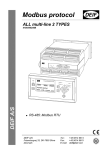
RFID KIT USER GUIDE
For printer models:
GL 4xxe Series
Read this User Guide before and during the operation of the
above accessory. Keep this Guide handy for future reference.
9001173A
1 General
Important information
This quick guide provides important information on how to setup your
new SATO product.
Be sure to read this quick guide thoroughly before using this printer. It
is an integral part of the product and should be kept in the immediate
vicinity of the device and available to the operating staff.
Limitation of liability
All information in this manual have been compiled under due
consideration of federal standards and regulations.
The manufacturer will not be held liable for damage resulting from:
z Disregarding these instructions
z Unintended use of the printer
z Unauthorized technical modifications
z Use of unapproved spare parts
z Use of unapproved consumables
FCC WARNING
Changes or modifications not expressly approved by the party responsible for
compliance could void the user’s authority to operate the equipment.
NOTICE
This equipment has been tested and found to comply with the limits for a
Class B digital device, pursuant to part 15 of the FCC Rules. These
limits are designed to provide reasonable protection against harmful
interference in a residential installation.
This equipment generates, uses and can radiate radio frequency energy
and, if not installed and used in accordance with the instructions, may
cause harmful interference to radio communications. However, there is
no guarantee that interference will not occur in a particular installation.
2
1.2 Explanation of symbols
This instruction manual uses various warning icons to help you
understand the safe operation of your printer. Explanations of the
icons are below.
WARNING!
Indicates neglectful or erroneous use may cause
irreparable damage to the product, serious injury to
the operator, or worse.
CAUTION!
Indicates a specific point where caution should be
used. The graphic within the triangle will indicate the
specific issue, i.e.; the sign on the left indicates a
caution for potential electrical shock.
CAUTION!
Indicates a potentially hazardous situation which,
if not avoided, may result in damage to your
product or host equipment.
NOTE!
Emphasizes useful tips or recommendations for
efficient and smooth operation of your printer.
3
1.3 Contact and Document Information
For SATO office locations worldwide. please visit www.satoworldwide.com
Version: GBS-GL4xxe-01rA-13-06-07-RFKUG © Copyright 1994 – 2007
All rights reserved. No part of this document may be reproduced or issued to third parties in any
form whatsoever without the express permission of SATO. The materials in this document are
provided for general information and are subject to change without notice. SATO assumes no
responsibilities for any errors that may appear.
4
Overview
This User Manual describes the operation and programming procedures for RFID smart
labels (with embedded RFID tags) on the SATO GL4xxe series printers fitted with the
RFID Kit.
By incorporating RFID commands into the SATO® Basic Programming Language
(SBPL) programs as described herein, users can produce smart labels to take
advantage of the power of RFID technology.
This manual is organized as follows:
1. Introduction to the RFID configuration options in the GL4xxe series printer
firmware
2. RFID Command Specifications
3. GL4xxe Coupler Design
4. Error Messages and Troubleshooting
5
1. Introduction to the RFID configuration options
RFID CONTROL Menu (GL4xxe Series)
RFID CONTROL
RFID Reader
Enable*
Disable
Max Retry
Error
Read Tag &
Eject
Enable*
Disable
Tag Type
Alien 9460 G2
Alien Squig G2
Avery AD220 G2
EPC G2 Phil1
EPC G2 Phil2
EPC G2 Phil3
EPC G2 Phil4
Flex Wing G2
Imp Banjo G2
KSW Excal G2
KSW Templar G2
Omron Wave G2
RAF Frog G2
RAF Short G2
Sym Trident G2
Sym Trident G2
TI Dallas G2
Comm Retry
2*
1 to 9
Tag Write Cnt 1
Failed Tag Cnt 1
Display
F/W Version
Overstrike
Style
Tag Void Cnt 1
Grid*
Error Type Msg
continued on
next page...
Tag Read Cnt 1
Error Handling
Overstrike*
None
Stop
Legend:
* = Default
Clear Tag Stat
Italicized items appear only when Admin User is set to Enable
(in the Advanced menu).
This item is information only, it is not an option that can be
adjusted.
1
Label Retry
10*
1 to 10
Read tag
6
...continued from previous page
RFID CONTROL
Custom Setting
C ustom Tag
D uplica te*
D isa ble
E nab le
W rite P ow er
6*
1 to 20
R ead P ow er
5*
1 to 20
E P C B yte Length
12*
8 to 32
E P C A dd ress
0*
0 to 32
U SR B yte Length
0*
0 to 32
U SR A ddress
0*
0 to 32
T ID B yte Len gth
8*
0 to 8
T ID A ddress
2*
0 to 32
B lo ck W rite Len
8*
0 to 32
Tag Class
Class 1*
GEN 2
Class 0
Class 0+
Class 1.19
Class Zuma
Read Tries
2*
1 to 10, infinite
Write Tries
9*
1 to 10
RFID Calibrate
To Run Press∞
Tag Position
0.0 mm*
-13 to 127 mm
Scan Start Pos
0.0 mm*
0.0 to 127 mm
Scan Length
76 mm*
0.0 to127 mm
Cal Min Power
1*
1 to 20
Cal Max Power
20*
1 to 20
Non-RFID
Warning
Disable*
Enable
7
Notes:
* = Default.
Italicized items appear only when Admin
User is set to Enable (in the PRINTER
SETUP menu).
Introduction to the RFID configuration options
RFID Menu Items (GL4xxe)
RFID Reader
This menu item enables or disables the RFID encoder. The default is Enable.
Tag Type
This menu item selects the tag type for use. See Table 3 for supported tag types listed in
alphabetical order. Other types may be added in the future.
Table 3. Supported RFID Tag Types (GL4xxe)
Tag Name
Bits
Alien Gen 2 Omni-Squiggle
96
Class 1,
Gen 2
Gen 2
Alien 9460 G2
Alien Gen 2 Squiggle
96
Class 1,
Gen 2
Gen 2
Alien Squig G2
Avery AD-220
(aka Runway)
96
Class 1,
Gen 2
Gen 2
Avery AD220 G2
Generic Philips
(coupler yellow)
96
Class 1,
Gen 2
Gen 2
EPC G2 Phil1
Generic Philips
(coupler orange)
96
Class 1,
Gen 2
Gen 2
EPC G2 Phil2
Generic Philips
(coupler red)
96
Class 1,
Gen 2
Gen 2
EPC G2 Phil3
Generic Philips
(coupler blue)
96
Class 1,
Gen 2
Gen 2
EPC G2 Phil4
Impinj Gen 2 Banjo
96
Class 1,
Gen 2
Gen 2
Imp Banjo G2
Protocol
Tag Class
8
Menu Selection
Table 3. Supported RFID Tag Types (GL4xxe)
Tag Name
Bits
Protocol
Tag Class
Menu Selection
KSW Gen 2 Excalibur
96
Class 1,
Gen 2
Gen 2
KSW Excal G2
KSW Gen 2 Templar
96
Class 1,
Gen 2
Gen 2
KSW Templar G2
Omron Gen 2 Wave
96
Class 1,
Gen 2
Gen 2
Omron Wave G2
Rafsec Gen 2 Frog
(3000790)
96
Class 1,
Gen 2
Gen 2
RAF Frog G2
Rafsec Short Dipole
(OneTenna)
96
Class 1,
Gen 2
Gen 2
RAF Short G2
RF IDentics Gen 2
Flex Wing
96
Class 1,
Gen 2
Gen 2
Flex Wing G2
Symbol Gen 2 Four T
96
Class 1,
Gen 2
Gen 2
Sym 4T G2
Symbol Gen 2 Trident
96
Class 1,
Gen 2
Gen 2
Sym Trident G2
TI Gen 2 Dallas
96
Class 1,
Gen 2
Gen 2
TI Dallas G2
Label Retry
NOTE: Label Retry only applies when the Error Handling mode is set to Overstrike.
This menu item selects the number of label retries that the RFID encoder will attempt
before declaring a fault. This may indicate a problem with the RFID encoder, the
coupler assembly, the printer setup, or the label stock. The default is 10 retries.
9
Introduction to the RFID configuration options
Tag Write Cnt
Displays the number of tags attempted to be written since the last Clear Tag Stat operation was initiated.
(See “Clear Tag Stat”.)
Failed Tag Cnt
Displays on the LCD the number of failed tag write attempts since the last Clear Tag Stat operation has
been initiated. (See “Clear Tag Stat”)
Tag Void Cnt
Always displays 0 unless the RFID encoder is used with an attached Online Barcode Validator (OBV).
When used with a validator, Tag Void Cnt represents how many valid RFID tags were overstruck due to
bad barcode scanning.
Tag Read Cnt
This menu item displays the number of tags read since the last Clear Tag Stat. (See “Clear Tag Stat”)
Non-RFID Warning
When set to Enable, this option causes the printer to check to make sure that non-RFID jobs are not
being printed on RFID labels (to prevent RFID labels from being wasted).
If RFID labels are installed in the printer, and a job is printed with at least one form that contains no RFID
commands, a fault will be declared and the data for the forms that contain no RFID commands will be
absorbed.
The default is Disable.
10
Introduction to the RFID configuration options
Admin User Menu Items (GL4xxe)
These menu items are visible only when the Admin User option is set to Enable in the Advanced menu.
(See the GL408/412e Operator’s Manual.)
IMPORTANT
Admin User menu items should only be used by authorized personnel.
Error Handling
This menu item selects the error handling mode for RFID failures. The default is Overstrike.
In Overstrike mode, each failed label prints with the Overstrike pattern and the form retries on a new
label until the Label Retry count is exhausted. Whether or not an error message will display (or the failed
label will reprint) depends upon the Max Retry Error setting.
In None mode, no specific action is taken when a tag fails to be programmed.
In Stop mode, when a tag fails to be programmed, the printer will halt and display the error message
“RFID Error: Check Media.” The label is discarded and reprinting of the label (if desired) must be
initiated from the host. When the error is cleared, the label with the failed tag moves forward until the
next label is in position to be printed.
Max Retry Error
Enables or disables Max Retry Error. If it is set to Disable, errors are not declared and the print content
for the current label is discarded. The default is Enable.
Clear Tag Stat
This menu item clears the Tag Write Cnt, Failed Tag Cnt, Tag Void Cnt, and Tag Read Cnt menu items.
11
Introduction to the RFID configuration options
Read Tag
Reads the tag in range of the internal RFID coupler and reports the tag data to the debug port and
momentarily displays it on the control panel’s LCD. It is mainly intended for data verification purposes.
IMPORTANT
This menu item does not position the RFID tag over the coupler. Make sure to position the tag
over the coupler to receive an accurate reading.
Read Tag & Eject
IMPORTANT
This menu item does not position the RFID tag over the coupler. Make sure to position the tag
over the coupler to receive an accurate reading.
The menu item works exactly the same as Read Tag (above), except that after the printer reads the tag,
it feeds the label to the next top-of-form.
Comm Retry
Selects the number of automatic (internal) retries that the printer will attempt on the same tag before
declaring a tag error and performing the Error Handling mode selected (Overstrike, Stop, or None).
The default value is 2.
Display F/W-Ver
Displays the reader firmware version on the control panel’s LCD.
Overstrike Style
Selects the style of the overstrike pattern. The default is Grid.
For the Grid option, a grid pattern is printed during overstrikes. For the Error Type Msg option, an error
message is printed to indicate which error occurred.
12
Introduction to the RFID configuration options
Table 4. Printed Overstrike Error Messages
Error Message
Explanation
Tag R/W Err x
Check media
The printer software attempted to write to or read from the
RFID tag, but the RFID encoder indicated that the tag could
not be written to, or read from.
Tag Comm Err x
Check cable
The printer software temporarily lost communication with the
RFID encoder, or communication between the printer
software and the RFID encoder was not synchronized and
had to be forced.
NOTE: The x in the error messages represents a number code that identifies the area
in the printer software or RFID encoder where the failure occurred.
Custom Setting
This menu item contains submenus that allow the RFID encoder to work with tag types that are not
listed in the Tag Type menu item.
NOTE: SATO cannot guarantee the performance of tag types not certified by SATO.
Custom Setting Submenus
Custom Tag
This menu item enables or disables the Custom Setting submenus. The default is Disable.
When Custom Tag is set to Disable, the settings in the Custom Setting submenus are ignored by
the RFID encoder.
When it is set to Enable, the RFID encoder uses the settings in the Custom Setting submenus,
which must be set to match the characteristics of the custom tag.
When it is set to Duplicate, the settings of the selected Tag Type menu item are copied into the
Custom Setting submenus, but are ignored by the RFID encoder.
13
Introduction to the RFID configuration options
Write Power
This menu item selects the write power level to be used in the RFID encoder. 1 is the lowest power level
setting, and 20 is the highest. The default is 6.
Read Power
This menu item selects the read power level to be used in the RFID encoder. 1 is the lowest power level
setting, and 20 is the highest. The default is 5.
EPC Byte Length
This menu item selects the number of bytes in the tag. The default is 12.
EPC Address
This menu item selects the starting location of the EPC block within the RFID tag memory. The default is
0.
USR Byte Length
This menu item selects the size of the USR block within the RFID
tag memory. The default is 0.
USR Address
This menu item selects the starting location of the USR block within the RFID tag memory. The default is
0.
TID Byte Length
This menu item selects the size of the TID block within the RFID tag memory. The default is 8.
TID Address
This menu item selects the starting location of the TID block within the RFID tag memory. The default is
2.
Block Write Len
This menu item selects the maximum number of bytes written to the
USR block within the RFID tag memory at one time. The default is 8.
14
Introduction to the RFID configuration options
Tag Class
Selects the class of the custom tag. Class 0+, Class 1.19, Gen 2, and Class Zuma tags are read/write.
Class 0 tags are read only. The default is Gen 2.
Read Tries
Selects how many times the RFID encoder will try each read command. The default is infinite, which
causes the encoder to try until the operation times out.
Write Tries
Selects how many times the RFID encoder will try each write command. The default is 9.
RFID Calibrate
Causes the printer to run calibration for the current RFID tags installed in the printer. After the
calibration is complete, the custom settings are changed to work with the tags installed. These settings
do not take effect until Custom Tag is set to Enable.
Tag Position
Determines how far the RFID tag position of the currently installed custom tags differs from the RFID
tag position of the standard SATO tag. SATO printers print at maximum speed with RFID labels that
have RFID tags in the standard position. The default is 0.0 mm.
15
Introduction to the RFID configuration options
Scan Start Pos
Determines where on the label the RFID calibration will begin. By default, the calibration procedure will
start at the beginning of the label (0.0 mm). To speed this up change this value to force the calibration to
begin after the beginning of the label.
Scan Length
Determines how much of the label will be scanned during the RFID calibration procedure. The default is
76mm.
Cal Min Power
Determines the minimum power level that the calibration procedure will use when attempting to find
the ideal power level. To speed this up, increase the value to exclude the lower power levels. The
default is 1.
Cal Max Power
Determines the maximum power level that the calibration procedure will use when attempting to find
the ideal power level. To speed this up, decrease this value to exclude the higher power levels. The
default is 20.
16
Introduction to the RFID configuration options
Requesting An RFID Report
This procedure prints a summarized RFID report. (This report also includes validator data if the printer
has a validator.)
GL4xxe
1. Take the printer offline and press ENTER to enter Menu mode.
2. Press the Down Arrow and ENTER buttons at the same time until a message “THE ENTER KEY IS
UNLOCKED” is displayed.
3. Press the Right Arrow key until DIAGNOSTICS displays.
4. Press ENTER to enter the DIAGNOSTICS menu. Make sure Printer Tests is
selected.
5. Press the Left Arrow button until RFID Report displays.
6. Press ENTER to print the report.
7. Press the Down and ENTER buttons at the same time to lock the ENTER button, then press the
LINE button to take the printer offline.
8. Press the LINE button again to take the printer online.
17
Introduction to the RFID configuration options
Advanced RFID Calibration
Tag Profiler
Read and Write power settings can be optimized using the Tag Profiler. Before running the
Tag Profiler, it is important to ensure that the proper Gap Sensing procedure has been
followed. It is recommended that you calibrate the printer to ensure that gap sensing settings
are correct.
To use the Tag Profiler, first ensure that the tag type that you have selected from the Tag Type
menu or page 3 [GL4xxe] for a list of supported tag types) either matches the tag type you are
about to calibrate or is at least of the same Class and data length (i.e. 64 or 96 bits). Next, check
that Custom Tag is set to Duplicate. The correct defaults will then be set for Custom Tag Class
and Tag (EPC Byte) Length.
Before initiating the calibration cycle, the Tag Profiler can be optimized by setting appropriate
limits on the following four custom entries:
•
Custom (Scan) Start Pos. Identifies the starting position of the calibration scan. The default
will start at the Top Of Form (TOF). To avoid inefficient scanning at points far away from the
target tag, set the (Scan) Start Pos within one inch of the center of the physical tag. E.g., if
the center of the tag is physically 76mm from the TOF, set (Scan) Start Pos to 51mm (25mm
(1 inch) before the center of the tag).
•
Custom Scan Length. This refers to the distance that the Tag Profiler will scan to determine
the optimum tag position. For improved performance, set Custom Scan Length to 51mm or
less. This will prevent the printer from looking for a tag far beyond its actual location.
•
Custom (Cal) Min Power. Sets the lower level that will be tested during calibration. To
speed up calibration, set Custom Min Power to two points lower than the Custom Read
Power that was set prior to initiating calibration.
18
•
Custom (Cal) Max Power. Sets the upper level that will be tested during calibration. To
speed up calibration, set Custom (Cal) Max Power to two points higher than the Custom
Write Power that was set prior to initiating calibration.
After setting the four custom entries, initiate the calibration cycle: access the RFID Calibrate
menu and press Enter. The calibration will proceed using the first three good tags. A calibration
progress indicator will update on the display. At the end of the calibration cycle, the Tag Profiler
will update the Custom Write Power, Read Power, and Tag Position.
Custom Tag Configurator
When Custom Tag is set to Duplicate, you can manually edit all the custom entries. This allows
you to overwrite the values discovered by the calibration in case you want to experiment further.
It is generally best to accept the calibration values as is unless you are intimately familiar with the
printer and its RFID processes.
Before you leave the Custom Tag Configurator, record the result from Custom Tag Position. This
will be useful when deriving the optimum position for your tag with your converter. Tell the
converter to move the tag from the current position by the amount in Custom Tag Position. A
positive value means move toward TOF, a negative value means move away from TOF.
Auto Inlay Locater
After you have run the Tag Profiler (using Custom Run Cal or RFID Calibrate) and recorded the
Custom Tag Position (offset from optimum position), you may now set Custom Tag to Enable in
preparation to use the media with the Auto Inlay Locator.
When Custom Tag is set to Enable, the Auto Inlay Locator uses the results of the Tag Profiler
calibration cycle to automatically advance the label to the correct encoding position, encode the tag
with the correct write/read power, back-feed the label to the TOF, and proceed normally to print the
full label without interruption.
19
2.RFID Command Specification
With the SATO GL4XXe, it is possible to return RFID information before writing data.
The printer supports Continuous, Tear-off, Dispenser and Cutter print mode options. Usually, writing
information to the RFID supply takes about 3 seconds to complete. Any abnormality that interrupts
the writing of information presented by RFID supply, takes about 5 seconds to show up as an error.
However, process time still varies, depending on the data size of the write information. If reading and
writing of RFID information fails due to defectiveness such as RFID supply, it takes about 10 seconds
to present as an error. Keystrokes do not register when information writing is under progress.
20
EPC Code Write
IP0
<49>16<50>16<30>16
ESC+IP0
Command
Hex code
Initial value
ESC
<1B>16
Nil
Parameter
e, d, k, a, u, m, f,p, s, t, c, n
Valid range
and term of
command
When power switch is The set command is not maintained.
OFF
Valid range within item The set parameter becomes invalid.
Valid range between The set parameter becomes invalid.
items
[Function]
This is a control function for Writing data to Gen2 RFID tag.
[Format]
<IP0> e: x , d:xxxxxxxxxxxxxxxxxxxxxxxx, k:xxxxxxxx, a:xxxxxxxx, p:xxxxxxxx, u:x….x, m:xxxxx,f:x, p:xx,
s:xx, c: xx, t:x, n:xxxxxxxxxxxx;
[Parameters]
e = [EPC Type]
a: EAN128 SSCC 96
c: EAN13 SGTIN 96
z: free mapping
d = [EPC Data]
24 digits if ‘e’ = z
17 digits if ‘e’ = a
13 digits if ‘e’ = c
Parameters when ‘e’ = Free mapping
k = [Kill code]
(Max. Data Length is 8 bytes, Data should be Hex (0 to F))
a = [Present Access Code]
(Max. Data Length is 8 bytes, Data should be Hex (0 to F))
p = [New Access Code]
(Max. Data Length is 8 bytes Data should be Hex (0 to F))
u = [User Memory]
(Max. Data Length depends on the tag manufacturer, Data should be Hex
(0 to F))
m = [Locking of blocks]
(5 digit Mask, 0: Unlock 1: Lock)
Mask byte (digit
from right)
Block
EPC Area (d)
00001 (0)
Kill Code (k)
00010 (1)
Access code (a)
00100 (2)
TID Area
01000 (3)
User Memory (u)
10000 (4)
When e = “a” (EAN128 SSCC 96) or “c”(EAN13 SGTIN 96)
f = filter value
(a value between 0 and 7)
s = total number of digits for serial reference
(Should be any value with 5 to 11, a combination
of s and c should be 17. Applicable only if
EAN128 SSCC 96 is selected)
t = total number of digits for item reference
(Should be any value with 1 to 7, a combination
of s and c should be 13. Applicable only if
EAN128 SSCC 96 is selected)
21
c = total number of digits for company prefix
n = serial Number (12digits)
(Should be any value with 6 to 12 according to
the number of digits of ‘s’ or ‘t’ parameters)
(Should be any value with 12 digits, only
applicable when EAN13 STGIN 96)
Coding Examples
【Example 1】
Description:
This example illustrates the method to write and lock EPC data of an unlocked tag and write
access code to the blank access code area.
Data:
<A>
<V>50<H>50<X22>,AAAA01234567890123456789
<IP0>e:z,d:AAAA01234567890123456789,a:1111AAAA,m:00001;
<Q1>
<Z>
【Example 2】
Description:
This example illustrates to write to a locked tag with out changing the access code.
Data:
<A>
<V>50<H>50<X22>,BBBB01234567890123456789
<IP0>e:z,d:BBBB01234567890123456789,p:1111AAAA,m:00001;
<Q1>
<Z>
【Example 3】
Description:
This example illustrates to write to a locked tag and to write a new access code.
Data:
<A>
<V>50<H>50<X22>,CCCC01234567890123456789
<IP0>e:z,d:CCCC01234567890123456789,p:1111AAAA,a:2222BBBB,m:00001;
<Q1>
<Z>
【Example 4】
Description:
This example illustrates to write data to the user memory blank of the tag.
Data:
<A>
<V>50<H>50<X22>,USER_MEMORY_56CHAR
<IP0>e:z,u:01234567890123456789012345678901234567890123456789012345;
<Q1>
<Z>
22
【Example 5】
Description:
This example illustrates to write EAN 128 data to the tag.
Data:
<A>
<V>50<H>50<X22>,3114F536CCCE4C3097000000
<IP0>e:a,d:34017587461099671,f:0,s:10,c:7;
<Q1>
<Z>
Note:
The EAN 128 data will be encrypted as per EPC Generation 1 Tag Data Standards Version 1.1
Rev.1.27 (SSCC 96).
【Example 6】
Description:
This example illustrates to write EAN 13 data to the tag.
Data:
<A>
<V>50<H>50<X22>,301803CB4F48B38000000001
<IP0>e:c,d:4003885006606,f:0,t:7,c:6,n:000000000001;
<Q1>
<Z>
Note:
The EAN 128 data is encrypted as per EPC Generation 1 Tag Data Standards Version 1.1
Rev.1.27 (SGTIN 96).
[Notes]
1. If EPC code cannot be coded into the tag, printer will execute an error action according to the settings
done from RFID mode.
2. Except “e”, which is imperative and in the fixed position (top), parameters can be omitted when not
needed.
3. Multiple print designations are only possible if IP0 command is used in combination with other print
data.
4. A word about access code, two parameters are used for access code (p: present access code and a:
New access code to be encoded into the tag)
- If ‘a’ parameter is used alone in an IP0 command, the data of ‘a’ parameter will be written in to
the access code area of the tag.
- If ‘p’ parameter is used alone in an IP0 command, the data of ‘p’ parameter will be used as a key
to write other memory blanks of the tag. The access code area remains unchanged.
- If both ‘a’ and ‘p’ parameters are used in an IP0 command, the data of ‘p’ parameter will be used
as a key to write other memory blanks of the tag and data of ‘a’ parameter will be written in to
the access code area of the tag.
23
5. The optional parameters could be omitted. Refer the table bellow to find optional parameters.
parameters
Gen2
e:
EPC Type
[F***]a
(EAN128 SSCC96)
d:
EPC Data
k:
Kill Code
×
×
[F**](8 digits)
a:
New Access Code
×
×
[F*](8 digits)
p:
Present access code
×
×
[F*](8 digits)
m:
Lock Mask
×
×
[F*](5 digits)
u:
User memory
×
×
[F**](1024 digits)
f:
filter value
[F***]0~7
[F***]0~7
×
s:
No of digits of serial
reference
[F***]5~11 *1
×
×
t:
Item reference
c:
company prefix
n:
Serial number
[F***]17 Digits
×
[F***]1~7
[F***]6~12 *1
×
x
[F***]z
(free mapping)
[F**]16、24
Digits
*2
×
[F***]6~12
*2
×
[F***]12digits
×
*1 Combination of company prefix
and serial reference should be 17
[F***] : Can not be omitted
[F**]
[F*]
[F***]c
(EAN13
SGTIN96)
[F***]13
Digits
*2 Combination of company prefix
and item reference should be 13
: More than one is needed
: Could be omitted
: Can not be
specified
24
EPC Code Read
ESC+IP1
Command
Hex code
Initial value
ESC
IP1
<1B>16 <49>16<50>16<31>16
Nil
Valid range
and term of
command
When power switch is
OFF
Valid range within item
Valid range between
items
Parameter
b
The set command is not maintained.
The set parameter becomes invalid.
The set parameter becomes invalid.
[Function]
This is a control function for reading data from the EPC code-compatible RFID tag.
[Format]
<IP1> ,b:X;
Where ,
b = Block Number
Block Name
Block No
EPC Area
1
TID Area
2
User
3
[Return Status Format]
[STX(02H)] + Data + [ETX(03H)]
Return status list
Item
Contents (Binary)
STX(02H)
Start code
Data
Data
ETX(03H)
End code
No. of bytes
1 byte
Depends on tags and blocks
1 byte
[Coding Example 1]
<A>
<IP1>,b:1;
<Z>
25
[Return Status Example 1]
When [8000 0000 4000 0001] is saved in an EPC-compatible tag.
02
Start code
38 30 30 30 30 30 30 30 34 30 30 30 30 30 30 31
03
End code
* In actuality, all data is continuous.
* Data is displayed in hexadecimal code.
[Return Status Example 2]
When there is no EPC-compatible tag .
02
Start code, error flag
45 50 43 5F 54 61 67 5F 45 72 72
Returning [EPC_Tag_Err] in ASCII char
03
End code
* In actuality, all data is continuous.
* Data is displayed in hexadecimal code.
[Notes]
1. This command cannot be used in combination with other commands.
2. This command is to be processed after the completion of print, not during the print.
3. It takes a few seconds after the command is sent until all return statuses are returned to the host
computer. If the port is closed before all return statuses are returned to the host, the tag data will not
be correctly returned and the data other than return status format is returned. You must then sort the
data before operating.
26
EPC Trade Mark Print
Hexadecimal
code
Initial value
Valid range
and term of
command
ESC
<1B>16
Nil
TM
<54>16<4D>16
When power switch is
OFF
Valid range within item
Valid range between
items
ESC+TM
Parameter
X
The set parameter is not maintained.
The set parameter becomes invalid.
The set parameter becomes invalid.
[Function]
This is a Graphic function specifying the print of EPC trade mark on a tag label.
[Format]
<TM>X
[Parameters]
X=[Logo ID No.]
1:
2:
[Coding Example1]
<A>
<V>50<H>50<TM>1
<Z>
[Coding Example2]
<A>
<V>50<H>50<TM>2
<Z>
[Notes]
1. Rotation <%> and Enlargement <L> are also available.
2. Specify the command Enlargement <L> right before <TM> in case of its usage.
3. The original print area is,
W143XH101 dots for logo1
W202XH101 dots for logo2 (without the designation of enlargement)
4. When the parameter X is left blank, the logo 1 will be printed.
27
Sequential numbering
Hexadecimal
code
Initial value
Valid range
and term of
command
ESC
<1B>16
Nil
F
<46>16
When power switch is
OFF
Valid range within item
Valid range between
items
ESC+F
Parameter
a a a a b c c c c, d d, e e, f
The set parameter is not maintained.
The set parameter becomes invalid.
The set parameter becomes invalid.
[Function]
This is a control function to specify data to be sequentially incremented or decremented.
In the data stream this command should be placed before EPC write command.
[Format]
<F> a a a a b c c c c (, dd, e e, f)
[Parameters]
aaaa
Number of times to repeat the same data : 0001-9999
b
Plus or minus symbol (+ for increments; - for decrements)
cccc
Value of step for sequence (0001-9999)
,dd
Number of digits for sequential numbering (01-99), if these digits are left out, the default is 8.
,ee
Number of digits free from sequential numbering (00-99) starting with the rightmost position.
If these digits are left out, the default is 0.
f
Decimal or Hexadecimal : 0 = decimal
1= Hexadecimal
When this digit is left out, the default is 0.
[Coding Example 1] Write EPC and Lock Tag
Number of times to repeat the same data : 1, incrementing :+, step of sequence:1,Number of digits for
Sequential numbering: 5, Number of digits free from sequential numbering: 0
<A>
<V> 100<H>100<X21>, Sequential Test
<F>1+1,5,0<IP0>e:z,d:1122334455ABCDEF01234567,a:1111AAAA,m:00001;
<Q> 2
<Z>
28
[Coding Example 2] Write EPC and User memory
Number of times to repeat the same data : 1, incrementing :+, step of sequence:100,Number of digits for
Sequential numbering: 3, Number of digits free from sequential numbering:2
<A>
<V>100<H>100<P>2<L>0202
<F>1+100,3,2,0<IP0>e:z,d:ABCDE1122334455ABCD056CC,u:ABC078CC;
<Q>3
<Z>
[Notes]
1. Up to Max. eight different sequential fields can be specified per label.
2. This command can not be used with the following commands.
Reverse Image command <(>
Line Feed command <E>
3. Among the RFID commands, only IP0 should be used in combination with this command. Only free
mapping functionality of (EPC area and User Area) IP0 command is valid with this command.
4. If EPC area and user area is specified in the same IP0 command, the sequential functionality will be valid
for both fields.
29
3. GL RFID Coupler Design
The GL4xxe RFID has a coupler design that supports a greater variety of tag types. You
can move the coupler horizontally by using the coupler handle. See figures on following
pages.
The coupler has four positions on a four inch printer.
Yellow:
1st Position (furthest inboard)
Orange:
2nd Position
Red:
3rd Position
Blue:
4th Position (furthest outboard on a 4 inch printer)
Once you select a tag type from the front panel, the following message will be
displayed on the LCD:
Set Antenna Pos
To x
If Done Press Enter
Where x is the word Yellow, Orange, Red and Blue
30
4. Adjusting the Coupler position
Remove the
thumbscrew
that secures
the lower front
cover to the
printer. Slide
the cover to
the left
(toward the
electrical half
of the printer)
to remove it.
31
Adjusting the Coupler position
Use the coupler handle to adjust the coupler so that the coupler position indicator points to
the correct color on the colored position strip.
Aligning the tabs, install the lower front cover (See RFID Kit Installation Guide) Step 2.
Secure the lower front cover to the printer using the thumbscrew.
32
4. Error Messages
The RFID encoder can detect a number of errors. When one of these errors occurs, the RFID encoder
alerts the printer to perform the currently selected error action
Error Message
Explanation
Solution
NON-RFID DATA On Rfid Tag
A job was printed that had no RFID
commands on at least one form of
the job while RFID tags were
installed in the printer and the NonRFID Warning menu item is set to
Enable.
Press LINE to clear the message.
Set Non-RFID Warning to Disable,
print a job with RFID commands
on every form, or install non-RFID
labels in the printer
RFID Comm Err
Check Cable
RFID error: communication cannot
be established with the RFID
encoder. Reader will be set to
Disable in the RFID (or RFID
CONTROL) menu and the
previous port settings restored
The RFID encoder firmware
version is not capable of operating
with the printer software.
Press LINE to clear the message.
Not
A lock command was executed on
a tag which does not support
locking. All Class 1 tags and most
Gen 2 tags support locking. Other
tag classes such as Class 0+,
Class 1.19, and Class Zuma do
not support locking.
Press LINE to clear the
message.
Remove the lock command from
the application.
Check
Error Handling = Overstrike in the
RFID (or RFID CONTROL) menu,
and the Label Retry count has
been exhausted.
A write was attempted on a
read-only tag.
Press LINE to clear the message.
RFID
FW
Mismatch
ERR:
RFID
LOCK
supported!
RFID MAX
System
Version
CMD:
RETRY
RFID TAG ERR: Read-Only
Tag
RFID TAG FAILED Check Media
RFID UNLOCK
Supported!
CMD:
Not
RFID ACS FIELD: Not Supported
RFID
KIL
Supported!
FIELD:
Not
Error Handling = Stop in the RFID
(or RFID CONTROL) menu, and
the RFID encoder could not read
the RFID tag.
An unlock command was executed
on a tag which does not support
locking.
The ACS field was accessed on a
tag which does not support the
ACS field
The KIL field was accessed on a
tag which does not support the
KIL field.
33
Press LINE to clear the
message.
Re-download the program file to
the printer.
Press LINE to clear the message.
Change media to writable tags or
remove the write command from
the application
Press LINE to clear the message.
Press LINE to clear the message.
Remove the unlock command
from the application.
Press LINE to clear the message.
Remove references to the ACS
field from the application
Press LINE to clear the message.
Remove references to the KIL field
from the application.
Troubleshooting
If you are having trouble with the RFID encoder, consult Table below for a list of symptoms and possible
solutions.
Symptom
Solution
No communication between
the printer and the reader
1. Make sure Reader = Enable in the RFID (or RFID
CONTROL) menu.
2. Use the RFID Test option in the RFID (or RFID CONTROL)
menu (Admin User enabled) to read and display the current RFID
tag content..
Tag failed
1. The label could be misaligned. Perform the Auto Calibrate
procedure to ensure the label is at top-of-form
2. Make sure the media are smart labels with RFID tags located
in the correct position.
3. The RFID tag could be defective. Try another tag.
4. Make sure the application does not send too few or too many
Inconsistent results
digits to the RFID tag.
Make sure the media is loaded correctly.
The RFID encoder works, but Make sure that both Error Handling and Label Retry are set to
it does not meet expectations desired values in the RFID (or RFID CONTROL) menu
34
35