1
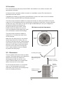
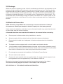
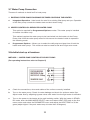
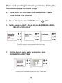
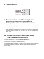
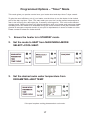
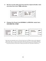
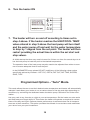
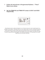
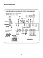
CHAPTER 1: INSTALLATION
Chapter 1 deals with installation of your Evoheat pool
heater and is predominately for use by your installer/
technician. Evo recommends however that owners make
themselves familiar with this chapter.
CHAPTER 2: OPERATION
Chapter 2 covers operation of your Evoheat pool heater
including basic and advanced operation modes and
maintenance/ troubleshooting.
Please take the time to read this manual thoroughly. Failure to
do so can void customer warranty, cause possible damage to
your heater, and may cause a loss of heater efficiency.
1
Table of CONTENTS
1. General Information
3
1.1
Introduction
3
1.2
Consumer and Safety Information
3
1.3
Energy Saving Tips
3
2.
Specifications
4
2.1 Technical specifications of DHP models
4
5
2.2 Dimensions
INSTALLATION
6
3.
General installation information
7
3.1
Inspection
7
3.2
Location
8
3.3
Clearances
8
3.4
Water Flow and Plumbing Setup
9
3.5
Drainage
10
3.6
Electrical Connection
10
3.7
Water Pump Connection
11
3.8a Initial start up at handover
11
3.8b Initial start up at handover
12
OPERATION
14
4.1
1. Existing filter pump/chlorinator/timer controls the heater
15
4.2
2. Heater controls a dedicated water pump – advanced operation
16
Programmed Options – “Timer” Mode
17
Programmed Options – “Auto” Mode
19
MAINTENANCE & TROUBLE SHOOTING
21
5.1
Maintenance
21
5.2
Troubleshooting
21
5.3
Error Descriptions and Solutions
23
APPENDIX A Wiring Diagrams
27
EVOHEAT Pump Warranty
28
Warranty Registration
29
2
1. General information
1.1 Introduction
This manual provides installation and operation instructions for EVOHEAT heat pumps. Read
these installation and operation instructions carefully before proceeding with the installation
and operation of your heater. Consult your EVOHEAT Distributor with any questions regarding
this equipment.
Installation and service must be performed by a qualified installer. The manufacturer will not
be responsible for any damage to the unit or injury caused by improper installation, operation
or maintenance.
1.2 Consumer and Safety Information
a. Evo recommends 27°C as the optimum water temperature for swimming.
b. The consumption of alcohol or drugs before or during spa or pool use can cause
drowsiness which could lead to unconsciousness and subsequent risk of drowning.
c. Immersion in water exceeding 38°C during pregnancy is not recommended.
d. The water temperature should always be checked with an accurate thermometer before
entering a spa or hot tub.
e. Persons with a medical history of heart disease, diabetes, circulatory or blood pressure
problems should consult their physician before using a hot tub or spa.
f. Persons taking any medication or drugs which induce drowsiness (e.g., tranquilizers,
antihistamines, or anticoagulants) should not use spas or hot tubs.
g. Prolonged immersion in hot water can induce hyperthermia.
1.3 Energy Saving Tips
It is important to note that a heat pump will not heat a pool as fast as a large gas pool heater.
If the pool water is allowed to cool significantly, it may take several days to return to the
desired swimming temperature. For weekend use, it is more economical to maintain the pool
water temperature at or near your desired swimming temperature. If you do not plan to use
your pool for a prolonged period, then you might choose to turn the heat pump completely
off or decrease the temperature setting of the control several degrees to minimize energy
consumption.
a. Use an accurate pool thermometer. A difference of 2°C , between 26°C and 28°C,
will significantly increase energy consumption.
b. Carefully monitor the water temperature of your pool in the summer time. You can
reduce heat pump usage due to warmer air temperatures.
c. When the pool is not to be used for long periods, turn off the heat pump.
d. Where possible, shelter the pool from prevailing winds with well-trimmed hedges or
other landscaping, cabanas, or fencing.
e. Always use a high quality pool cover when practical. Besides providing a valuable water
saving feature, a pool cover will dramatically reduce heat loss. See attached appendix
for further information.
3
2. Specifications
2.1 Technical specifications of DHP models
Model
DHP20
DHP30
DHP40
DHP50
DHP601
DHP603
Recommended Litres
Max Pool Size
20,000
30,000
40,000
50,000
60,000+
60,000+
HEAT OUTPUT
MAX *
KW
11.3
16.0
18.9
26
32.5
32.5
Heat output @
24°C Air
KW
10.1
13.2
17.8
21.3
25.0
25.0
Heat output @
15°C Air
KW
7.5
10.5
16
17.8
21.5
21.5
Power input @
24°C Air
W
1800
2600
3500
4300
5000
5000
Efficiency @
24°C Air
COP
5.6
5.1
5.1
5.0
5.0
5.0
Evoheat recommend using a pool cover on any pool that is heated
Running
Current
7.7
11.8
15.9
19.5
22.7
8.3
30
40
45
20
Circuit Breaker
A
15
25
Power
Requirements
V/Ph/Hz
240/1/50
240/1/50 240/1/50
240/1/50 240/1/50 415/3/50
Rotary
Rotary
Scroll
Compressor
Type
Scroll
Heat
Exchanger
Double Titanium Coil in PVC Barrel
Refrigerant
R407c Gas
Scroll
Scroll
Noise Level
dB(A)
51
54
56
58
58
58
Water
Connection
mm
50
50
50
50
50
50
Optimal Water
Flow
Litres/min
50
75
100
125
150
150
Dimensions
L/W/H
mm
580/545/
750
Weight Net /
Gross
Kg
61/66
100/110
106/116
118/128
650/650/
880
66/71
4
96/106
2.2 Dimensions
Water
outlet
G
Water
inlet
G
Horizontal view
Vertical view
5
CHAPTER 1
INSTALLATION
Before installation it is very important to ensure 4 variables
are carefully checked to allow the unit to operate correctly
1. Adequate Air Flow
2. Correct water flow volume
3. Correct electrical connection & supply
4. Heater condition
1. Air Flow
Installing the heater indoors or in an enclosed space will result in very poor performance and
can in extreme cases damage the heater. Ensure the heater is installed in a well ventilated
area with plenty of fresh air, a minimum gap between walls/fences etc of 600mm on the
sides and 1500mm overhead clearance.
Important: Ensure that the cold air off the top of the heater does not recycle through
the heater.
SEE PAGE 8 FOR FURTHER INFORMATION
2. Water Flow
It is CRITICAL that there is sufficient water flow to the unit. Incorrect water flow can cause a
loss of efficiency and possible damage to the unit. Optimal water flow rates are listed in the
Evoheat sales brochure and in this manual on page __. It is imperative that water flow is kept
as close as possible to these flow rates. Correct water flow not only offers optimal heater
performance, but may also prevent possible damage to your heater.
SEE PAGE 9 FOR FURTHER INFORMATION
3. Electrical Connection
Always use a qualified Electrician to perform any electrical work. Ensure the power cable and
circuit breaker are of a suitable size for the heater being installed. Also check that there is
adequate voltage and current available at the heater connection to run the unit. Voltage range
should be 220-240 volts for single phase, and 380-415 volts for 3 phase units. Voltage ranges
outside these parameters will cause heater damage and void your warranty. Correct phase
connection is important with 3 phase heaters.
SEE PAGE 10 FOR FURTHER INFORMATION
6
4. Heater Condition
Check the heater packaging upon delivery for any obvious signs of damage. Inform your
supplier IMMEDIATELY if there is any evidence of rough handling.
When the heater has been removed from the packaging check the refrigerant gauge on the
front panel of the unit. The gauge should be showing a pressure of approx 1Mpa on the
outside black band – any less than this figure means there may be a leak in the refrigerant
system and you should immediately contact your Evoheat Dealer.
Example of a unit with a
refrigerant leak and zero
pressure – notify
Evoheat Dealer.
3. General installation information
3.1 Inspection
Inspect the packaging, the heater and other items after receipt for possible damage in
transportation. Please contact your EVOHEAT dealer immediately should you suspect any
damage has occurred during transportation.
Install your EVOHEAT heat pump in accordance with the procedures in this manual. Always
check that your installation will comply with local building and council regulations.
Correct installation is required to ensure safe and efficient operation of your pool heater.
Installation requirements for EVOHEAT heat pumps include the following:
a. Appropriate site location and clearances.
b. Sufficient air ventilation.
c. Correct electrical connection.
d. Adequate water flow.
This manual provides the information needed to meet these requirements.
Review all application and installation procedures completely before continuing
the installation
7
3.2 Location
Evo recommend the heat pump should ONLY be installed in an outdoor location with
appropriate ventilation.
In the event that a suitable outdoor location is unavailable contact Evo Industries for
specialist technical advice.
If installing the heater on an existing pump/filtration system the heater must be installed
AFTER the filter and BEFORE the chlorinator/sanitizer.
The heat pump should be installed on a flat level surface as close as possible to the pool.
Large runs of uninsulated piping can significantly contribute to heat loss. A rough estimate
of heat loss over a 30m pipe run can be as high as 600 Watts per hour per 5 degrees of
temperature difference between the
air/ground and the pool water. These
Minimum required clearances
losses need to be taken into account
over long distances and piping may need
to be insulated to reduce heat leakage.
300mm (rear)
The heat pump should be installed a
maximum of 1m below the water level
of the pool/spa.
600mm
(side)
Make sure the heat pump is not located
where large amounts of water may runoff from a roof into the unit. Sharp sloping
roofs without gutters will allow excessive
amounts of rain water mixed with debris
from the roof to be forced through the
unit. A water deflector may be needed
to protect the heat pump.
3.3 Clearances
The unit needs continuous fresh air whilst
running. The heater draws up to 80m3/min
ambient air through the sides and
discharges through the top fan cowl.
Leave sufficient space for unobstructed
airflow into and out of the heater.
Do not locate the heater in an enclosed
area, or the discharged cold air will
recirculate into the unit and consequently
lower the heating efficiency.
600mm
(side)
900mm (front)
Overhang with gutter
Rain runoff must be
directed away from
unit
1500mm minimum
clearance, overhead
300mm
minimum
clearance,
rear
900mm minimum
clearance, front
8
3.4 Water Flow and Plumbing Setup
All EVOHEAT heat pumps have a factory preset internal water flow switch. If there is
insufficient water flow the heater will not operate.
Before connecting the heater to the plumbing, all piping must be thoroughly flushed
to ensure no debris can enter the heater. Failure to remove pipe debris can jam or
damage the flow switch and may cause damage to the heater.
When cleaning the pool it is advisable to turn off your heater as restricted water flow
may cause the heater to shut down and indicate low water flow fault (P08 error).
Typical plumbing layouts
Heater spacing
minimum, 24"
Multiple Heat Pump Installation
Pool Spill 0ver Spa – One Pump System
Pool Spill 0ver Spa – Two Pump System
LEGEND
3
C
D
F
–
–
–
–
3 way valve
Chlorinator (if used)
Drain
Filter
H
P
R
S
–
–
–
–
Heat Pump
Pump
Return
Skimmer
9
–
–
–
–
–
Flow Switch (ADT Kit)
Throttle valve
Thermometer
By-Pass Check Valve
Flow Meter
3.5 Drainage
Whilst the heater is operating, water in the air condenses on the fins of the evaporator. In the
instance of high humidity, the condensate may be several litres per hour. This may give the
impression that the heater is leaking, however this is a normal function of heat pumps. The
heater will automatically activate reverse cycle or de-icing mode when required which also
increases condensate discharge. This normally occurs at temperatures below 8 degC. The
condensate water will discharge through the base of the heater. As an option a pipe can be
connected to the drain on the base of the unit to direct condensate water to an appropriate
location.
3.6 Electrical Connection
NOTE: EVO heat pumps MUST be connected by a licensed electrician. Under no
circumstances should you attempt to install or repair your heat pump yourself.
Heater electrical installation undertaken by an unlicensed installer may cause electric shock
or even death, and will void the warranty.
A licensed electrician must read the information in this manual before connecting.
a. Ensure power is disconnected during installation or service.
b. Always comply with the national and local electrical codes and standards.
c. Ensure electrical cable size is adequate for heater requirements at the installation
location.
d. The heater must be equipped with a circuit breaker and isolation device.
e. circuit breaker must be installed between the heater and the water circulation pump if
the water pump is hard-wired into the heater. Please note recommended circuit breaker
sizes make no allowance for a water pump hard wired into the heater.
f. Evo strongly recommends the installation of a Residual Current Device.
g. The unit must be well earthed.
h. Connect the wire controller with the supplied cable. If a longer cable is required it can
be lengthened to suit the application up to a maximum 100m run.
Remove the front panel to access the electrical connection terminals of the heater.
The electrical wiring diagram is affixed to the inside of the front panel.
SEE APPENDIX “A” FOR WIRING DIAGRAM INFORMATION
10
3.7 Water Pump Connection
There are 2 methods to install an Evo heat pump.
1. EXISTING FILTER PUMP/CHLORINATOR/TIMER CONTROLS THE HEATER
4
Integrated Operation – Ideal mode for retro fit to existing filter/pump set ups. Operation
of the filter pump controls the heater start and shut down timing.
2. HEATER CONTROLS A DEDICATED WATER PUMP
This option is required for Programmed Options modes. This water pump is installed
for heater circulation only.
This method requires the water pump to be hard-wired into the heater via the Pump
Power inlet. With the water pump wired in this manner the heater is able to operate in
the following mode.
4
Programmed Options – Allows you to select the daily start and stop time of both the
heater and water pump. This mode can also be used as Set and Forget auto mode.
3.8a Initial start up at handover
METHOD 1 - WATER PUMP CONTROLS THE HEAT PUMP
(For operating instructions refer to Chapter 2)
a. Check the connections, wires and cables of the unit are correctly installed.
b. Turn on the water pump. Check for water leakage and check for optimum water flow.
Adjust water flow by adjusting bypass valves until water flow through heater is sufficient.
c. Turn on the power to the heater at the main isolating switch. With the heater in STANDBY mode, enter the MAIN MODE SELECT menu and select HEAT. ESC back to the first
menu screen and select the PARAMETER menu and adjust the HEAT TEMP to 30 degrees (adjust higher if the pool water temp is hotter than 30 degrees)
11
d. Then press the ON/OFF button on the remote controller. The heater will start shortly
after water flow commences. Actual conditions can be checked by going to the MAIN
menu and selecting UNIT status to view water inlet and outlet, refrigerant pipe and
ambient air temps.
e. After the unit runs for a few minutes, check whether the air discharged by the fan is
noticeably cooler than the ambient air. If no cold air check the refrigerant gauge on the
heater to ensure there is a refrigerant charge in the unit. Another way to determine if
the heater is working correctly is to view MAIN MENU>UNIT STATUS. Check to see if
the WATER OUT temp is higher than the WATER IN temp. If no cold air or the water in
and out temps are the same check the refrigerant gauge on the heater to ensure there
is a refrigerant charge in the unit. Check also the INLET WATER TEMP is lower than the
HEAT TEMP set point.
f. Turn the water pump off while the unit is running. The unit should stop working
automatically and a water flow error will appear. If not, contact Evo Industries
for further advice.
g. Turn the water pump on again and wait for the unit to restart.
3.8b Initial start up at handover
METHOD 2 - HEAT PUMP CONTROLS THE WATER PUMP
a. Check the connections, wires and cables of the unit are correctly installed.
b. Turn on the power to the heater at the main isolating switch. With the heater in
STANDBY mode, enter the MAIN menu and select HEAT. ESC back to the first menu
screen and select the PARAMETER menu and adjust the HEAT TEMP to 30 degrees
(adjust higher if the pool water temp is hotter than 30 degrees). Go to the PUMP
sub-menu in the PARAMETER menu and change to SPECIAL.
c. Go to the TIME sub-menu and set the current day and time. Set the TIMER ON to a
value 5mins in the future and the TIMER OFF value 10mins in the future.
12
d. Press the ON/OFF button on the remote controller. The water pump will start when the
time reaches the TIMER ON setting and the heat pump will start 60 seconds after this
value. The heat pump will shut down when it reaches the TIMER OFF value and the
water pump will shut down 30 seconds afterwards . Actual conditions can be checked
by going to the MAIN menu and selecting UNIT status to view water inlet and outlet,
refrigerant pipe and ambient air temps.
e. With the water pump running, check for water leakage and check for optimum water
flow. Adjust water flow by adjusting bypass valves until water flow through heater is
sufficient.
f. After the unit runs for a few minutes, check whether the air discharged by the fan is
noticeably cooler than the ambient air. Another way to determine if the heater is working
correctly is to view MAIN MENU>UNIT STATUS. Check to see if the WATER OUT temp
is higher than the WATER IN temp. If no cold air check or the water in and out temps
are the same check the refrigerant gauge on the heater to ensure there is a refrigerant
charge in the unit. Check also the INLET WATER TEMP is lower than the HEAT TEMP
set point.
13
CHAPTER 2
OPERATION
Button Description and Operation
1. On/Off Button Press this to turn the unit on or off. Status will be STANDBY mode when heater is off.
2 & 4. Up/Down Selection Buttons Use to modify data while heater is in standby mode.
Use to view data while heater is running.
3. Prg Button Used to access controller menu
options.
5. Esc Button Used to confirm changes to menu settings.
Used in view mode to move back through the menu options.
Enter Button used to select menu option.
6.
14
There are 2 operating modes for your heater. Follow the
instructions below for Quick setup.
4.1 EXISTING FILTER PUMP/CHLORINATOR/TIMER CONTROLS THE HEATER
1. Ensure the heater is in STANDBY mode
1
OFF
2. Set the mode to HEAT - Press 6 from MAIN MENU>MODE SELECT>COOL/HEAT
If the pool requires cooling please select cool mode
3. Set the desired swim water temperature from PARAMETER>HEAT TEMP
If cooling mode is selected modify the COOL TEMP value
15
4. Turn the heater ON
5. The heater will turn on and off according to times set on your (A) chlorinator or timing device (B)
the temperature set on the controller once reached
At initial startup the water pump may need to be in operation for several days to allow
the heat pump to heat the pool to the desired temperature. The operation time of the
water pump may also need to be adjusted from winter to summer to ensure adequate
time to heat the pool.
In the PARAMETER menu please DO NOT modify any of the following values unless
specifically advised by Evoheat – DEF CYC, DEF IN, DEF OUT, DEF TIME, SYSTEM,
SAVE, TYPE.
4.2 HEATER CONTROLS A DEDICATED WATER
PUMP – ADVANCED OPERATION
This option allows the user to control Programmed Options mode.
The water pump is dedicated to heater circulation only.
This method requires the water pump to be hard-wired into the heater via the Pump Power
inlet. With the water pump wired in this manner the heater is able to operate in the
following modes.
16
Programmed Options – “Timer” Mode
This mode gives you precise control over your heater start and stop times 7 days a week.
To gain the most efficiency out of your heater, use the timer to run the heater in the hottest
part of the day, say 9am – 6pm. This may mean your pool isn’t at the perfect temperature at
3am in the morning for a late night dip, or an early morning swim. This is the most efficient
running mode. Setting the timer will require interaction with your heater, and may mean heater
operating hours will need to be extended during the cooler months of the year. Evoheat can
provide an accurate computer model of your pool's requirements in terms of heater run time.
Please contact Evoheat for further advice.
1. Ensure the heater is in STANDBY mode.
2. Set the mode to HEAT from MAIN MENU>MODE
SELECT>COOL/HEAT.
3. Set the desired swim water temperature from
PARAMETER>HEAT TEMP
If the pool requires cooling please select cool mode.
17
4. Set the current date and time and the required heater start
and stop time from TIME submenu
5. Change the Pump from NORMAL to SPECIAL mode from
PARAMETER>PUMP
Page down the parameter menu to find the last screen. NORMAL pump mode means the
water pump will run 24 hours continuously while the power is on to the heater. SPECIAL
pump mode means the water pump will turn on 60 seconds before the compressor in the
heat pump switches on and shut off 60 seconds after the compressor switches off.
18
6. Turn the heater ON
7. The heater will turn on and off according to times set in
step 4 above. If the heater reaches the HEAT/COOL TEMP
value entered in step 3 above the heat pump will turn itself
and the water pump off and wait for the water temperature
to drop by 1 degree from the set point. The heater will then
restart providing the actual time is within the set start and
stop values.
At initial startup the timer may need to be set for 24 hour run time for several days to allow the heat pump to heat the pool to the desired temperature.
The operation time of the heat pump may also need to be adjusted from winter to summer to ensure adequate time to heat the pool.
In the PARAMETER menu please DO NOT modify any of the following values unless
specifically advised by Evoheat – DEF CYC, DEF IN, DEF OUT, DEF TIME, SYSTEM,
SAVE, TYPE.
Programmed Options – “Auto” Mode.
This mode allows the user to set their desired water temperature and heater will automatically
maintain it and allows your heater to run at various times of the day and night depending on
conditions, by controlling the dedicated water circulation pump. See below for further information.
Use your pool at any time day or night at your set temperature. Set the heater on auto mode
and walk away and forget about it! This means the heater will operate as required at various
times of the day and night. Optimum heater performance is achieved when the air temperatures are at their maximum. This option provides the ultimate in convenience and maximises
your return from your pool investment.
19
1. Follow all instructions in Programmed Options – “Timer”
Mode menu above.
2. Set the TIME ON and TIME OFF values to 00:01 and 00:00
respectively.
By setting the timer to allow the heater to run 24 hours a day you can “set and forget” the
operation of the heater. The heater will turn on the water pump, run until it reaches the desired
water temperature and then switch itself and the water pump off. Once the water temperature drops by 1 degree inside the internal plumbing of the unit the heater will restart the water
pump and heat pump and heat again to the desired temperature. This process will continue
indefinitely until manually overridden.
20
Maintenance and
Troubleshooting
5.1 Maintenance
General Maintenance
a. The unit should be serviced once a year by a authorised EVO technician. If the unit is
located in a coastal area, more frequent maintenance may be necessary.
b. The unit is designed to withstand only normal rainfall. It is NOT recommended to use
a hose or high pressure water cleaner to flush the internals of the heater. Pressurised
water may cause damage to the heater. Compressed air is acceptable however care
must be taken with the fins of the condensor.
Ensure the unit has sufficient water flow at all times to operate correctly by keeping all
filters, skimmer boxes and pump filter baskets clean. Check any bypass valves or other
equipment for correct operation and setting. Refer to specifications for correct water
flow volume for your heater.
5.2 Troubleshooting
The unit will not run
a. Is the screen of control panel lit? If not, make sure the electrical wires and cables are
correctly connected and the power is on. Ensure any circuit breaker devices are set to
the ON position and press the ON button on your controller. Check your controller cable
is plugged in and is not damaged. If the unit has been shut off or the power has been
interrupted the heater will not restart for a 5 minute period to protect the compressor.
Wait 5 minutes before attempting a restart.
b. Is there sufficient water flow? If the screen displays a water flow related error check the
water flow. Is the water pump in operation and the system free of debris that may cause
a blockage? Disconnect pool cleaners to ensure proper water flow.
c. Is the current pool/spa water temperature higher than the set temperature on the
controller? If so the unit will not operate until the pool/spa water temperature falls below
the set temperature on the controller.
d. Check the unit is set to run at the correct time and date. Please check your current
timing or temperature modes on your controller – you may have programmed the unit
to turn on at a different time/date.
e. Check the controller for error messages and refer to table below.
21
The unit is running but not heating
a. Is the fan functioning? If not contact EVOHEAT for service information
b. Is the air discharged from the top of the fan noticeably cooler than the ambient
temperature? If not, check the refrigerant gauge on the bottom panel of the heater.
Another way to determine if the heater is working correctly is to view MAIN
MENU>UNIT STATUS. Check to see if the WATER OUT temp is higher than the
WATER IN temp. Check also the INLET WATER TEMP is lower than the HEAT TEMP
set point. If the gauge shows less than 0.8MPA (the outside black band) contact
EVOHEAT to check the refrigerant system.
c. Ensure sufficient fresh airflow around the unit as per installation instructions. Make
sure cold air discharged from the top of the unit does not recycle back through the
heater. Check and clean the condenser fins if they are dirty or blocked.
d. The unit will periodically defrost when the ambient air temperature is lower than
8 degrees C.
Heater runs continuously
a. Check the set temperature is at your desired level and that the pool water temperature
is at or below this set point.
b. Possible electrical component failure – contact EVOHEAT
Water appearing around unit base
a. Condensation is a normal by product of running a pool heat pump.
b. Possible water leak. Check the discharge for the presence of chlorine. If the water
has no chlorine then it is condensation and is normal. Another method of
checking is to turn the heater off and run the water pump continuously for a period
of 2-4 hours. If the water dries out then it was condensation. If there is a continuous
leak contact EVOHEAT for service.
Temperature on controller is different from actual pool temperature
a. Possible temperature drop due to plumbing. Try increasing set temperature to reach
your desired swim temp
b. Possible fouling of sensor or faulty sensor
22
Error Descriptions and Solutions
Error
E09
EE01
E12
E03
P08
Description
Power phase
system protect
Compressor
error
High pressure
Temp difference
error
Water flow failure
Possible reasons
Solution
1. wrong phase sequence (3
phase unit)
reverse any two phases
2. possible loose conection
check all wires to ensure
correctly terminated
3. short circuit between
terminals +12V and E3 open
(single phase unit)
set up short circuit between
+12V and E3
1. incorrect or loose wiring
check wiring against
schematic and connection
2. abnormal power supply
check power supply to ensure
correct voltage current etc
3. compressor failure
check status of compressor
by ensuring equal resistance
across all compressor
connections
1. incorrect or loose wiring
check wiring against
schematic and connection
2. low water flow volume but
still above minimum
increase water flow - check
filters, pumps etc for debris
3. Water backflowing through
heater when water pump is off
check for air leaks and ensure
no water is flowing
4. Fan not running
Check fan is running when
water pump and heater is on
5. High Pressure switch failure
check device or replace
1. incorrect wiring
check wiring against
schematic
2. obstruction in water piping
(incl. filter) system
clean water pipes - backflush
system if possible
3. water flow volume under
minimum
increase water flow - check
filters, pumps etc for debris
4. water flow switch failure
check, clean device or replace
23
E08
Communication
failure
1.faulty connection between
main PCB and controller
remove cable, check plugs &
sockets and cable for damage
2. controller hardware failure
check device and wiring
connections -replace if req’d
3. main PCB hardware failure
check device and wiring
connections -replace if req’d
P14
Anti freeze temp
1. The sensor is open or short
circuit
check sensor and wiring
connections -replace if req’d
P13
Pipe temp 1
1. The sensor is open or short
circuit
check sensor and wiring
connections -replace if req’d
P05
Ambient temp
1. The sensor is open or short
circuit
check sensor and wiring
connections -replace if req’d
P01
Water in
1. The sensor is open or short
circuit
check sensor and wiring
connections -replace if req’d
P02
Water out
1. The sensor is open or short
circuit
check sensor and wiring
connections -replace if req’d
E11
Low pressure
1. incorrect or loose wiring
check wiring against
schematic and connection
2. low or no refrigerant charge
Check refrigerant gauge on
unit. A zero or close to zero
reading indicates a loss of
refrigerant. Contact Evoheat
3. Low Pressure switch failure
check device or replace
1. Inlet water temp is too low
If water is close to freezing unit
will not run to prevent damage.
Wait until water is warmer
2. Inlet water temp sensor is
faulty
check sensor and wiring
connections -replace if req’d
P07
Frostbite protect
PP03
Coil 1 sensor
1. The sensor is open or short
circuit
check sensor and wiring
connections -replace if req’d
PP04
Coil 2 sensor
1. The sensor is open or short
circuit
check sensor and wiring
connections -replace if req’d
24
Appendix A – Wiring Diagrams
25
Wiring Diagrams
26
Wiring Diagrams
27
EVOHEAT Pump Warranty
1. The titanium heat exchanger tubing is guaranteed against corrosion for a period of
fifteen (15) years from the date of purchase when used with chlorine, salt, bromine
or sea water.
2. The compressor is guaranteed for five (5) years from the date of purchase.
3. All other parts are guaranteed for two (2) years from the date of purchase
4. This warranty covers all labour for twelve (12) months from the date of purchase
5. This warranty excludes any defect or injury caused by or resulting from misuse, abuse,
neglect, accidental damage, improper voltage, vermin infestation, incompetent
installation, any fault not attributable to faulty manufacture or parts, any modifications
which affect the reliability or performance of the unit.
6. This warranty does not cover the following:
a. Natural Disasters (hail, lightening, flood, fire etc.)
b. Rust or damage to paintwork caused by a corrosive atmosphere
c. When serviced by an unauthorized person without the permission of Evo Industries Australia
d. When a unit is installed by an unqualified person
e. Where a unit is incorrectly installed
f. When failure occurs due to improper or faulty installation
g. Failure due to improper maintenance (refer Operating Instructions)
h. ‘No Fault Found’ service calls where the perceived problem is explained within the Operation Instructions
i. Costs associated with delivery, handling, freighting, or damage to the product
in transit.
7. If warranty service is required you should:
a. contact Evo Industries Australia on 07 3162 2213 or via our Contact Us page on our web site
b. provide a copy of your receipt as proof of purchase
c. have completed the online warranty registration or provide a completed warranty card.
8. Home service is available within the normal operating area of your Evo Industries authorized Service Centre. Service outside this area will incur a travelling fee.
Unless otherwise specified to the purchaser, the benefits conferred by this express warranty
and additional to all other conditions, warranties, rights and remedies expressed or implied
by the Trade Practices Act 1974 and similar consumer protection provisions contained in
legislation of the States and Territories and all other obligations and liabilities on the part of
the manufacturer or supplier and nothing contained herein shall restrict or modify such rights,
remedies, obligations or liabilities.
28
Warranty Registration
To register your Warranty, please enter the following details or go online at
www.evoheat.com.au/warranty to register directly at our website. Fields with a star (*) must
be filled in before continuing. For information about what Evo Industries Australia will do with
your personal details, please refer to our Privacy Disclaimer.
Family Name: *
Given Name: *
Preferred Title: *
Age Group: *
18-24 25-34 35-44 45-54 55-64 64+
Street Address: *
Suburb: *
Postcode: *
State: *
Email: *
Please tell us about which EvoHeat product you bought, who you bought it from and what
you will be using it for.
Product & Model: *
Serial Number:
Authorised Installer:
Date Purchased: *
Date Installed:
Receipt Number: *
Company you bought it from: *
Did you purchase the item when you purchased your pool?:
If you purchased it after the pool, how many years did you wait?:
What size is your pool or spa?:
Why did you choose an EVOHEAT product?:
30
31
32
33
34
35