1
IMI CORNELIUS INC g One Cornelius Place g Anoka, MN 55303-6234 Telephone (800) 238-3600 Facsimile (612) 422-3246 Service Manual FCB (SOLID-STATE) POST-MIX DISPENSER Four-Flavor/Hot-gas Defrost With V3 Electronics IMPORTANT: TO THE INSTALLER. It is the responsibility of the Installer to ensure that the water supply to the dispensing equipment is provided with protection against backflow by an air gap as defined in ANSI/ASME A112.1.2-1979; or an approved vacuum breaker or other such method as proved effective by test. Water pipe connections and fixtures directly connected to a potable water supply shall be sized, installed, and maintained according to Federal, State, and Local Codes. Part No. 326093000 August 11, 1988 Revised: February 4, 1992 THIS DOCUMENT CONTAINS IMPORTANT INFORMATION This Manual must be read and understood before installing or operating this equipment IMI CORNELIUS INC; 1988–92 PRINTED IN U.S.A TABLE OF CONTENTS Page SAFETY INFORMATION . . . . . . . . . . . . . . . . . . . . . . . . . . . . . . . . . . . . . . . . . . . . . . . . . . . . 1 RECOGNIZE SAFETY INFORMATION . . . . . . . . . . . . . . . . . . . . . . . . . . . . . . . 1 UNDERSTAND SIGNAL WORDS . . . . . . . . . . . . . . . . . . . . . . . . . . . . . . . . . . . . 1 FOLLOW SAFETY INSTRUCTIONS . . . . . . . . . . . . . . . . . . . . . . . . . . . . . . . . . 1 CO2 (CARBON DIOXIDE) WARNING . . . . . . . . . . . . . . . . . . . . . . . . . . . . . . . . 1 SHIPPING, STORING, OR RELOCATING UNIT . . . . . . . . . . . . . . . . . . . . . . . 1 GENERAL DESCRIPTION . . . . . . . . . . . . . . . . . . . . . . . . . . . . . . . . . . . . . . . . . . . . . . . . . . 3 GENERAL DESCRIPTION . . . . . . . . . . . . . . . . . . . . . . . . . . . . . . . . . . . . . . . . . . . . . . 3 UNIT DESCRIPTION . . . . . . . . . . . . . . . . . . . . . . . . . . . . . . . . . . . . . . . . . . . . . . . . . . . 3 THEORY OF OPERATION . . . . . . . . . . . . . . . . . . . . . . . . . . . . . . . . . . . . . . . . . . . . . . 4 DEFROST SYSTEMS . . . . . . . . . . . . . . . . . . . . . . . . . . . . . . . . . . . . . . . . . . . . . . . . . . 4 MANUAL DEFROST SYSTEMS . . . . . . . . . . . . . . . . . . . . . . . . . . . . . . . . . . . . . . . . . 5 AUTOMATIC DEFROST SYSTEMS . . . . . . . . . . . . . . . . . . . . . . . . . . . . . . . . . . . . . . 5 ‘‘SLEEP’’ (SLEEP TIME) . . . . . . . . . . . . . . . . . . . . . . . . . . . . . . . . . . . . . . . . . . . . 5 ‘‘WAKE UP’’ (WAKE UP TIME) . . . . . . . . . . . . . . . . . . . . . . . . . . . . . . . . . . . . . . 5 INSTALLATION . . . . . . . . . . . . . . . . . . . . . . . . . . . . . . . . . . . . . . . . . . . . . . . . . . . . . . . . . . . . 7 UNPACKING AND INSPECTION . . . . . . . . . . . . . . . . . . . . . . . . . . . . . . . . . . . . . . . . 7 IDENTIFICATION OF LOOSE–SHIPPED PARTS . . . . . . . . . . . . . . . . . . . . . . . . . . 7 INSTALLING BEATERS AND SCRAPER BLADES . . . . . . . . . . . . . . . . . . . . . . . . 10 ELECTRICAL POWER REQUIREMENTS . . . . . . . . . . . . . . . . . . . . . . . . . . . . . . . . . 10 DOMESTIC UNIT . . . . . . . . . . . . . . . . . . . . . . . . . . . . . . . . . . . . . . . . . . . . . . . . . . 10 EXPORT UNIT . . . . . . . . . . . . . . . . . . . . . . . . . . . . . . . . . . . . . . . . . . . . . . . . . . . . 10 SELECTING LOCATION . . . . . . . . . . . . . . . . . . . . . . . . . . . . . . . . . . . . . . . . . . . . . . . . 10 INSTALLING UNIT . . . . . . . . . . . . . . . . . . . . . . . . . . . . . . . . . . . . . . . . . . . . . . . . . . . . . 11 PLACING UNIT IN OPERATING LOCATION . . . . . . . . . . . . . . . . . . . . . . . . . . 11 INSTALLING DRIP TRAY SUPPORTS, DRIP TRAY, AND CUP REST . . . . 11 INSTALLING DRIP TRAY DRAIN KIT . . . . . . . . . . . . . . . . . . . . . . . . . . . . . . . . 11 INSTALLING PRIMARY CO2 REGULATOR ASSEMBLY ON CO2 CYLINDER . . . . . . . . . . . . . . . . . . . . . . . . . . . . . . . . . . . . . . . . . . . . . . . . . . . . . . . 11 CONNECTING SOFT DRINK TANKS CO2 LINES TO PRIMARY CO2 REGULATOR ASSEMBLY . . . . . . . . . . . . . . . . . . . . . . . . . . . . . . . . . . . . . . . . . . 12 PREPARING UNIT SYRUP INLET LINES FOR CONNECTION TO SOFT DRINK TANKS . . . . . . . . . . . . . . . . . . . . . . . . . . . . . . . . . . . . . . . . . . . . . . . . . . . . 12 CONNECTING PLAIN WATER INLET SUPPLY LINE TO UNIT . . . . . . . . . . 12 CONNECTING ELECTRICAL POWER CIRCUIT TO UNIT . . . . . . . . . . . . . . 13 PREPARATION FOR OPERATION . . . . . . . . . . . . . . . . . . . . . . . . . . . . . . . . . . . . . . . 13 50 OR 60HZ OPERATION AND BEATER MOTOR SELECT . . . . . . . . . . . . 13 TURNING ON ELECTRICAL POWER TO UNIT . . . . . . . . . . . . . . . . . . . . . . . 14 TURNING ON CO2 SUPPLY TO UNIT . . . . . . . . . . . . . . . . . . . . . . . . . . . . . . . 14 TURNING ON PLAIN WATER SUPPLY TO UNIT . . . . . . . . . . . . . . . . . . . . . . 14 CONNECTING SOFT DRINK TANKS TO UNIT SYRUP SYSTEM . . . . . . . 14 ADJUSTING BRIX (WATER–TO–SYRUP) RATIO OF DISPENSED PRODUCT 15 FILLING FREEZE CYLINDERS WITH PRODUCT . . . . . . . . . . . . . . . . . . . . . 16 ADJUSTING BEATER MOTOR CURRENT (EITHER SIDE) . . . . . . . . . . . . . 16 i 326093000 TABLE OF CONTENTS (cont’d) Page PROGRAMMING MAIN MENU SELECTIONS ONTO MESSAGE DISPLAY 16 PROGRAMMING ‘‘DEFROST’’ (AUTOMATIC) SETTINGS INTO UNIT . . . 16 PROGRAMMING ‘‘SLEEP’’ (SLEEP TIME) INTO UNIT . . . . . . . . . . . . . . . . . 16 PROGRAMMING ‘‘WAKE UP’’ (WAKE UP) TIME INTO UNIT . . . . . . . . . . . . 17 PROGRAMMING POINT OF SALE MESSAGE DISPLAY . . . . . . . . . . . . . . . 17 ADJUSTING ‘‘VIS SET’’ (PRODUCT VISCOSITY) OF DISPENSED PRODUCT . . . . . . . . . . . . . . . . . . . . . . . . . . . . . . . . . . . . . . . . . . . . . . . . . . . . . . . . 17 DISPLAYED EVAPORATOR REFRIGERATION COILS INLETS AND COMMON OUTLET SENSORS TEMPERATURES . . . . . . . . . . . . . . . . . . . . 17 ‘‘VOLTAGE’’ (DISPLAYED VOLTAGE READOUT) . . . . . . . . . . . . . . . . . . . . . . 17 PROGRAMMING COMPONENTS ‘‘DIAGNOSE’’ (DIAGNOSTIC MODE) INTO UNIT . . . . . . . . . . . . . . . . . . . . . . . . . . . . . . . . . . . . . . . . . . . . . . . . . . . . . . . 17 DISPLAYING ‘‘TOTALS’’ (DISPLAYED CYCLES AND HOURS TOTALS) ONTO MESSAGE DISPLAY . . . . . . . . . . . . . . . . . . . . . . . . . . . . . . . . . . . . . . . . 17 DISPLAYED ERROR CONDITIONS . . . . . . . . . . . . . . . . . . . . . . . . . . . . . . . . . . . . . . 17 OPERATORS INSTRUCTIONS . . . . . . . . . . . . . . . . . . . . . . . . . . . . . . . . . . . . . . . . . . . . . . 19 CONTROL PANEL SWITCHES AND DISPLAYED MESSAGES . . . . . . . . . . . . . . 19 CONTROL PANEL SWITCHES . . . . . . . . . . . . . . . . . . . . . . . . . . . . . . . . . . . . . . 19 CONTROL PANEL DISPLAY MESSAGES . . . . . . . . . . . . . . . . . . . . . . . . . . . . 20 FREEZE CYLINDERS MANUAL OR AUTOMATIC DEFROST SYSTEMS . . . . . 21 MANUAL DEFROST SYSTEM . . . . . . . . . . . . . . . . . . . . . . . . . . . . . . . . . . . . . . 21 AUTOMATIC DEFROST SYSTEM . . . . . . . . . . . . . . . . . . . . . . . . . . . . . . . . . . . 21 ‘‘SLEEP’’ (SLEEP TIME) . . . . . . . . . . . . . . . . . . . . . . . . . . . . . . . . . . . . . . . . . . . . . . . . 21 ‘‘WAKE UP’’ (WAKE UP TIME) . . . . . . . . . . . . . . . . . . . . . . . . . . . . . . . . . . . . . . . . . . . 22 FACEPLATE RELIEF VALVES . . . . . . . . . . . . . . . . . . . . . . . . . . . . . . . . . . . . . . . . . . . 22 PRODUCT SAMPLE VALVES . . . . . . . . . . . . . . . . . . . . . . . . . . . . . . . . . . . . . . . . . . . 22 PRODUCT SHUTOFF VALVES . . . . . . . . . . . . . . . . . . . . . . . . . . . . . . . . . . . . . . . . . . 22 PRIMARY CO2 REGULATOR . . . . . . . . . . . . . . . . . . . . . . . . . . . . . . . . . . . . . . . . . . . 22 SECONDARY CO2 REGULATORS . . . . . . . . . . . . . . . . . . . . . . . . . . . . . . . . . . . . . . 22 CARBONATED WATER FLOW REGULATORS . . . . . . . . . . . . . . . . . . . . . . . . . . . . 22 SYRUP FLOW REGULATORS . . . . . . . . . . . . . . . . . . . . . . . . . . . . . . . . . . . . . . . . . . 22 DISPENSING VALVES . . . . . . . . . . . . . . . . . . . . . . . . . . . . . . . . . . . . . . . . . . . . . . . . . 22 DISPENSED PRODUCT CONDITIONS . . . . . . . . . . . . . . . . . . . . . . . . . . . . . . . . . . . 23 OPERATING CHARACTERISTICS . . . . . . . . . . . . . . . . . . . . . . . . . . . . . . . . . . . . . . . 24 OPERATING UNIT . . . . . . . . . . . . . . . . . . . . . . . . . . . . . . . . . . . . . . . . . . . . . . . . . . . . . 24 REPLENISHING SYRUP SUPPLY . . . . . . . . . . . . . . . . . . . . . . . . . . . . . . . . . . . . . . . 24 PRODUCT FLAVOR CHANGE . . . . . . . . . . . . . . . . . . . . . . . . . . . . . . . . . . . . . . . . . . 24 CHECKING CO2 SUPPLY . . . . . . . . . . . . . . . . . . . . . . . . . . . . . . . . . . . . . . . . . . . . . . 25 CLEANING AND SANITIZING . . . . . . . . . . . . . . . . . . . . . . . . . . . . . . . . . . . . . . . . . . . 25 DAILY CLEANING . . . . . . . . . . . . . . . . . . . . . . . . . . . . . . . . . . . . . . . . . . . . . . . . . 25 SANITIZING . . . . . . . . . . . . . . . . . . . . . . . . . . . . . . . . . . . . . . . . . . . . . . . . . . . . . . 25 CLEANING CONDENSER COIL . . . . . . . . . . . . . . . . . . . . . . . . . . . . . . . . . . . . . . . . . 25 LUBRICATION . . . . . . . . . . . . . . . . . . . . . . . . . . . . . . . . . . . . . . . . . . . . . . . . . . . . . . . . 25 ADJUSTMENTS . . . . . . . . . . . . . . . . . . . . . . . . . . . . . . . . . . . . . . . . . . . . . . . . . . . . . . . 25 CARBONATED WATER FLOW RATE . . . . . . . . . . . . . . . . . . . . . . . . . . . . . . . . 25 326093000 ii TABLE OF CONTENTS (cont’d) Page CO REGULATORS . . . . . . . . . . . . . . . . . . . . . . . . . . . . . . . . . . . . . . . . . . . . . . . . 26 BRIX (WATER–TO–SYRUP) ‘‘RATIO’’ OF DISPENSED PRODUCT . . . . . . 26 ADJUSTING BEATERS MOTORS CURRENTS . . . . . . . . . . . . . . . . . . . . . . . 26 ADJUSTING CARBONATOR TANK LIQUID LEVEL . . . . . . . . . . . . . . . . . . . . 26 PROGRAMMING MAIN MENU SELECTIONS ONTO MESSAGE DISPLAY 26 SETTING ‘‘CLOCK’’ (TIME OF DAY) . . . . . . . . . . . . . . . . . . . . . . . . . . . . . . . . . 26 PROGRAMMING ‘‘DEFROST’’ (AUTOMATIC) SETTINGS INTO UNIT . . . 26 PROGRAMMING ‘‘SLEEP’’ (SLEEP TIME) INTO UNIT . . . . . . . . . . . . . . . . . 26 PROGRAMMING ‘‘WAKE UP’’ (WAKE UP) TIME INTO UNIT . . . . . . . . . . . . 27 PROGRAMMING POINT OF SALE MESSAGE DISPLAY . . . . . . . . . . . . . . . 27 ADJUSTING ‘‘VIS SET’’ (PRODUCT VISCOSITY) OF DISPENSED PRODUCT . . . . . . . . . . . . . . . . . . . . . . . . . . . . . . . . . . . . . . . . . . . . . . . . . . . . . . . . 27 DISPLAYED EVAPORATOR REFRIGERATION COILS INLETS AND COMMON OUTLET SENSORS TEMPERATURES . . . . . . . . . . . . . . . . . . . . 27 ‘‘VOLTAGE’’ (DISPLAYED VOLTAGE READOUT) . . . . . . . . . . . . . . . . . . . . . . 27 PROGRAMMING COMPONENTS ‘‘DIAGNOSE’’ (DIAGNOSTIC MODE) INTO UNIT . . . . . . . . . . . . . . . . . . . . . . . . . . . . . . . . . . . . . . . . . . . . . . . . . . . . . . . 27 DISPLAYING ‘‘TOTALS’’ (DISPLAYED CYCLES AND HOURS TOTALS) ONTO MESSAGE DISPLAY . . . . . . . . . . . . . . . . . . . . . . . . . . . . . . . . . . . . . . . . 27 DISPLAYED ERROR CONDITIONS . . . . . . . . . . . . . . . . . . . . . . . . . . . . . . . . . 27 WATER STRAINER SCREEN AND DOUBLE LIQUID CHECK VALVE MAINTENANCE . . . . . . . . . . . . . . . . . . . . . . . . . . . . . . . . . . . . . . . . . . . . . . . . . . . . . . . 28 CLEANING CO2 GAS CHECK VALVES . . . . . . . . . . . . . . . . . . . . . . . . . . . . . . . . . . 28 SERVICE AND MAINTENANCE . . . . . . . . . . . . . . . . . . . . . . . . . . . . . . . . . . . . . . . . . . . . . 29 PREPARING UNIT FOR SHIPPING, STORING, OR RELOCATING . . . . . . . . . . 29 PERIODIC INSPECTION . . . . . . . . . . . . . . . . . . . . . . . . . . . . . . . . . . . . . . . . . . . . . . . 29 REMOVAL OF DRIP TRAY, BACK PANEL, SIDE PANELS, TOP PANEL, LOWER FRONT ACCESS PANEL, AND CONDENSER COILS ACCESS PANEL . . . . . . 29 DRIP TRAY . . . . . . . . . . . . . . . . . . . . . . . . . . . . . . . . . . . . . . . . . . . . . . . . . . . . . . . 29 BACK PANEL . . . . . . . . . . . . . . . . . . . . . . . . . . . . . . . . . . . . . . . . . . . . . . . . . . . . . 29 SIDE PANELS . . . . . . . . . . . . . . . . . . . . . . . . . . . . . . . . . . . . . . . . . . . . . . . . . . . . 29 TOP PANEL . . . . . . . . . . . . . . . . . . . . . . . . . . . . . . . . . . . . . . . . . . . . . . . . . . . . . . 29 LOWER FRONT ACCESS PANEL . . . . . . . . . . . . . . . . . . . . . . . . . . . . . . . . . . . 30 CONDENSER COILS ACCESS PANEL . . . . . . . . . . . . . . . . . . . . . . . . . . . . . . 30 LUBRICATION . . . . . . . . . . . . . . . . . . . . . . . . . . . . . . . . . . . . . . . . . . . . . . . . . . . . . . . . 30 CARBONATORS WATER PUMP MOTORS . . . . . . . . . . . . . . . . . . . . . . . . . . . 30 DISPENSING VALVES CAGED O–RINGS AND BEATERS DRIVE SHAFTS SEALS ASSEMBLIES . . . . . . . . . . . . . . . . . . . . . . . . . . . . . . . . . . . . . 30 CLEANING CONDENSER COILS . . . . . . . . . . . . . . . . . . . . . . . . . . . . . . . . . . . . . . . . 34 ADJUSTMENTS . . . . . . . . . . . . . . . . . . . . . . . . . . . . . . . . . . . . . . . . . . . . . . . . . . . . . . . 34 ADJUSTING PLAIN WATER PRESSURE REGULATORS . . . . . . . . . . . . . . . 34 ADJUSTING CARBONATED WATER FLOW RATE . . . . . . . . . . . . . . . . . . . . 34 ADJUSTING CO2 REGULATORS . . . . . . . . . . . . . . . . . . . . . . . . . . . . . . . . . . . 35 ADJUSTING BRIX (WATER–TO–SYRUP) ‘‘RATIO’’ OF DISPENSED PRODUCT . . . . . . . . . . . . . . . . . . . . . . . . . . . . . . . . . . . . . . . . . . . . . . . . . . . . . . . . 36 PRODUCT CARBONATION ADJUSTMENT . . . . . . . . . . . . . . . . . . . . . . . . . . 37 iii 326093000 TABLE OF CONTENTS (cont’d) Page ADJUSTING BEATER MOTOR CURRENT (EITHER SIDE) . . . . . . . . . . . . . 37 ADJUSTMENTS, AND PROGRAMMING MAIN MENU SELECTIONS, COMPONENTS ‘‘DIAGNOSE’’ (DIAGNOSTIC MODE), AND ‘‘TOTALS’’ (DISPLAYED CYCLES AND HOURS) INTO UNIT . . . . . . . . . . . . . . . . . . . . . . . . . . 38 PROGRAMMING MAIN MENU SELECTION ONTO MESSAGE DISPLAY 38 SETTING CLOCK (TIME OF DAY) . . . . . . . . . . . . . . . . . . . . . . . . . . . . . . . . . . . 39 PROGRAMMING ‘‘DEFROST’’ (AUTOMATIC) SETTINGS INTO UNIT . . . 39 PROGRAMMING ‘‘SLEEP’’ (SLEEP TIME) INTO UNIT . . . . . . . . . . . . . . . . . 41 PROGRAMMING ‘‘WAKE UP’’ (WAKE UP TIME) INTO UNIT . . . . . . . . . . . . 42 PROGRAMMING POINT OF SALE MESSAGE DISPLAY . . . . . . . . . . . . . . . 42 ADJUSTING ‘‘VIS SET’’ (PRODUCT VISCOSITY) OF DISPENSED PRODUCT . . . . . . . . . . . . . . . . . . . . . . . . . . . . . . . . . . . . . . . . . . . . . . . . . . . . . . . . 44 ‘‘VIS READ’’ (ACTUAL VISCOSITY READOUT) OF PRODUCT IN FREEZE CYLINDERS . . . . . . . . . . . . . . . . . . . . . . . . . . . . . . . . . . . . . . . . . . . . . . 43 DISPLAYED EVAPORATOR REFRIGERATION COILS INLETS AND COMMON OUTLET SENSORS TEMPERATURES. . . . . . . . . . . . . . . . . . . . . 43 ‘‘VOLTAGE’’ (DISPLAYED VOLTAGE READOUT) . . . . . . . . . . . . . . . . . . . . . . 43 PROGRAMMING COMPONENTS ‘‘DIAGNOSE’’ (DIAGNOSTIC MODE) INTO UNIT . . . . . . . . . . . . . . . . . . . . . . . . . . . . . . . . . . . . . . . . . . . . . . . . . . . . . . . 44 DISPLAYING ‘‘TOTALS’’ (DISPLAYED CYCLES AND HOURS TOTALS) ONTO MESSAGE DISPLAY. . . . . . . . . . . . . . . . . . . . . . . . . . . . . . . . . . . . . . . . 46 DISPLAYED ERROR CONDITIONS . . . . . . . . . . . . . . . . . . . . . . . . . . . . . . . . . . . . . . 46 CLEANING AND SANITIZING . . . . . . . . . . . . . . . . . . . . . . . . . . . . . . . . . . . . . . . . . . . 46 YEARLY (OR AFTER WATER SYSTEM DISRUPTION) . . . . . . . . . . . . . . . . . . . . . 49 SERVICING CARBONATORS WATER PUMPS WATER STRAINER SCREENS . . . . . . . . . . . . . . . . . . . . . . . . . . . . . . . . . . . . . . . . . . . . . . . . . . . . . . . . 50 SERVICING CARBONATORS WATER PUMPS DOUBLE LIQUID CHECK VALVES . . . . . . . . . . . . . . . . . . . . . . . . . . . . . . . . . . . . . . . . . . . . . . . . . . 50 REPLENISHING SYRUP SUPPLY . . . . . . . . . . . . . . . . . . . . . . . . . . . . . . . . . . . . . . . 51 REPLENISHING CO2 SUPPLY . . . . . . . . . . . . . . . . . . . . . . . . . . . . . . . . . . . . . . . . . . 53 SYRUP FLAVOR CHANGE . . . . . . . . . . . . . . . . . . . . . . . . . . . . . . . . . . . . . . . . . 53 CLEANING CO2 GAS CHECK VALVES . . . . . . . . . . . . . . . . . . . . . . . . . . . . . . . . . . 54 REPLACING FREEZE CYLINDER BEATER DRIVE SHAFT BEARING . . . . . . . 54 SHUTTING UNIT DOWN . . . . . . . . . . . . . . . . . . . . . . . . . . . . . . . . . . . . . . . . . . . 54 REMOVING BEATER DRIVE MOTOR AND BEATER DRIVE SHAFT ASS’Y FROM UNIT . . . . . . . . . . . . . . . . . . . . . . . . . . . . . . . . . . . . . . . . . . . . . . . . . . . . . . . . . . . 55 INSTALLING BEATER DRIVE SHAFT BEARING ASS’Y . . . . . . . . . . . . . . . . . . . . 55 INSTALLING BEATER DRIVE SHAFT ASS’Y AND BEATER DRIVE MOTOR IN UNIT . . . . . . . . . . . . . . . . . . . . . . . . . . . . . . . . . . . . . . . . . . . . . . . . . . . . . . . . . . . . . . 56 RESTORING UNIT OPERATION . . . . . . . . . . . . . . . . . . . . . . . . . . . . . . . . . . . . . . . . 57 REPLACING BEATER DRIVE SHAFT SEAL ASS’Y 57 ....................... REPLACING FREEZE CYLINDER BEATER DRIVE MOTOR ............... 57 ADJUSTING CARBONATOR TANK LIQUID LEVEL . . . . . . . . . . . . . . . . . . . . . . . . 58 TROUBLESHOOTING . . . . . . . . . . . . . . . . . . . . . . . . . . . . . . . . . . . . . . . . . . . . . . . . . . . . . . 63 ONE OR MORE CONTROL PANEL SWITCHES NOT OPERATING. . . . . . . . . . 63 ALL CONTROL PANEL SWITCHES NOT OPERATING. . . . . . . . . . . . . . . . . . . . . 63 CONTROL PANEL SWITCHES CANNOT BE DEACTIVATED. . . . . . . . . . . . . . . . 64 326093000 iv TABLE OF CONTENTS (cont’d) Page PARTIAL MESSAGE OR DULL (POORLY ILLUMINATED) DISPLAY. . . . . . . . . . 64 ONE OR MORE FAULT MESSAGES NOT OPERATING. . . . . . . . . . . . . . . . . . . . 64 ALL FAULT MESSAGES NOT OPERATING. . . . . . . . . . . . . . . . . . . . . . . . . . . . . . . 64 ‘‘CO2 OUT’’ FAULT1. MESSAGE GOES ON DURING OPERATION. . . . . . . . . . 65 ‘‘H2O OUT’’ FAULT MESSAGE GOES ON DURING OPERATION. . . . . . . . . . . 65 ‘‘SYRUP 1’’ OR ‘‘SYRUP 2’’ FAULT MESSAGE GOES ON DURING OPERATION. . . . . . . . . . . . . . . . . . . . . . . . . . . . . . . . . . . . . . . . . . . . . . . . . . . . . . . . . . 65 ‘‘ERROR 1’’ OR ‘‘ERROR 2’’ FAULT MESSAGE GOES ON DURING OPERATION. . . . . . . . . . . . . . . . . . . . . . . . . . . . . . . . . . . . . . . . . . . . . . . . . . . . . . . . . . 65 FREEZE CYLINDERS AUTOMATIC DEFROST SYSTEM DOES NOT OPERATE. . . . . . . . . . . . . . . . . . . . . . . . . . . . . . . . . . . . . . . . . . . . . . . . . . . . . . . . . . . . . 65 UNIT DOES NOT GO OFF AUTOMATIC DEFROST CYCLE. . . . . . . . . . . . . . . . . 66 MANUAL DEFROST CYCLE DOES NOT OPERATE WHEN ‘‘DEFROST‘’ SWITCH IS PRESSED. . . . . . . . . . . . . . . . . . . . . . . . . . . . . . . . . . . . . . . . . . . . . . . . . . 66 DEFROST CYCLE DOES NOT CANCEL AFTER PRESSING ‘‘CANCEL DEFROST’’ SWITCH. . . . . . . . . . . . . . . . . . . . . . . . . . . . . . . . . . . . . . . . . . . . . . . . . . . 66 CARBONATOR WATER PUMP MOTOR WILL NOT OPERATE. . . . . . . . . . . . . . 67 CARBONATOR WATER PUMP WILL NOT SHUT OFF. . . . . . . . . . . . . . . . . . . . . . 67 ERRATIC CARBONATOR WATER PUMP CYCLING. . . . . . . . . . . . . . . . . . . . . . . . 67 BRIX (WATER–TO–SYRUP) ‘‘RATIO’’ TOO LOW. . . . . . . . . . . . . . . . . . . . . . . . . . . 67 BRIX (WATER–TO–SYRUP) ‘‘RATIO’’ TOO HIGH. . . . . . . . . . . . . . . . . . . . . . . . . . 68 IMPROPER PRODUCT DISPENSED. . . . . . . . . . . . . . . . . . . . . . . . . . . . . . . . . . . . . 68 PRODUCT WILL NOT DISPENSE OUT OF DISPENSING VALVE, IN ONLY SMALL AMOUNTS, OR ONLY LIQUID. . . . . . . . . . . . . . . . . . . . . . . . . . . . . . . . . . . . . . . . . . . 68 FREEZE CYLINDER DOES NOT REFILL AT ALL TIMES WHEN DISPENSING 68 FROZEN PRODUCT CONSISTENCY VARIES EXCESSIVELY. . . . . . . . . . . . . . . 68 CYLINDER FREEZE–UP. . . . . . . . . . . . . . . . . . . . . . . . . . . . . . . . . . . . . . . . . . . . . . . . 68 WARRANTY . . . . . . . . . . . . . . . . . . . . . . . . . . . . . . . . . . . . . . . . . . . . . . . . . . . . . . . . . . . . . . 70 LIST OF FIGURES FIGURE 1. FCB (SOLID STATE) POST-MIX FOUR-FLAVOR DISPENSER . . . . 3 FIGURE 2. FLOW DIAGRAM . . . . . . . . . . . . . . . . . . . . . . . . . . . . . . . . . . . . . . . . . . . . 6 FIGURE 3. BEATERS AND SCRAPER BLADES INSTALLATION . . . . . . . . . . . . 8 FIGURE 4. FREEZE CYLINDER CUTAWAY VIEW . . . . . . . . . . . . . . . . . . . . . . . . . 9 FIGURE 5. OPERATING CONTROLS . . . . . . . . . . . . . . . . . . . . . . . . . . . . . . . . . . . . 31 FIGURE 6. UNIT INTERNAL COMPONENTS . . . . . . . . . . . . . . . . . . . . . . . . . . . . . 32 FIGURE 7. SELF–CLOSING DISPENSING VALVE . . . . . . . . . . . . . . . . . . . . . . . . . 33 FIGURE 8. SERVICING BEATER DRIVE SHAFT SEAL ASSEMBLY . . . . . . . . . 33 FIGURE 9. CONTROL PANEL . . . . . . . . . . . . . . . . . . . . . . . . . . . . . . . . . . . . . . . . . . . 38 FIGURE 10. MASTER AND RELAY CIRCUIT BOARDS . . . . . . . . . . . . . . . . . . . . . 40 FIGURE 11. LIQUID CHECK VALVE ASSEMBLY . . . . . . . . . . . . . . . . . . . . . . . . . . 49 FIGURE 12. WATER STRAINER SCREEN AND DOUBLE LIQUID CHECK VALVE . . . . . . . . . . . . . . . . . . . . . . . . . . . . . . . . . . . . . . . . . . . . . . . . . . . . . . . . . . . . . . . . 52 FIGURE 13. CO2 GAS CHECK VALVE . . . . . . . . . . . . . . . . . . . . . . . . . . . . . . . . . . . 54 FIGURE 14. BEATER DRIVE MOTOR AND SHAFT SEAL ASS’Y REPLACEMENT . . . . . . . . . . . . . . . . . . . . . . . . . . . . . . . . . . . . . . . . . . . . . . . . . . . . . . . 56 v 326093000 TABLE OF CONTENTS (cont’d) Page LIST OF FIGURES (CONT’D) FIGURE 15. CARBONATOR LIQUID LEVEL CONTROL SWITCH ADJUSTMENT . . . . . . . . . . . . . . . . . . . . . . . . . . . . . . . . . . . . . . . . . . . . . . . . . . . . . . . . 59 FIGURE 16. REFRIGERATION FLOW DIAGRAM (ONE OF TWO REFRIGERATION SYSTEMS SHOWN) . . . . . . . . . . . . . . . . . . . . . . . . . . . . . . . . . . 60 FIGURE 17. WIRING DIARGRAM . . . . . . . . . . . . . . . . . . . . . . . . . . . . . . . . . . . . . . . 61 LIST OF TABLES TABLE 1. DESIGN DATA . . . . . . . . . . . . . . . . . . . . . . . . . . . . . . . . . . . . . . . . . . . . . . . 4 TABLE 2. LOOSE-SHIPPED PARTS . . . . . . . . . . . . . . . . . . . . . . . . . . . . . . . . . . . . . 7 TABLE 3. MAIN MENU SELECTIONS . . . . . . . . . . . . . . . . . . . . . . . . . . . . . . . . . . . . 40 TABLE 4. DIP SWITCH FUNCTIONS . . . . . . . . . . . . . . . . . . . . . . . . . . . . . . . . . . . . . 41 TABLE 5. BEATER MOTOR SELECT . . . . . . . . . . . . . . . . . . . . . . . . . . . . . . . . . . . . . 41 TABLE 6. POINT OF SALES DISPLAY MESSAGES . . . . . . . . . . . . . . . . . . . . . . . . 42 TABLE 7. “TOTALS” (DISPLAYED CYCLES AND HOURS TOTALS) MENU . . . 45 TABLE 8.DISPLAYED ERROR CONDITIONS . . . . . . . . . . . . . . . . . . . . . . . . . . . . . 46 ACCESSORIES AND TOOLS . . . . . . . . . . . . . . . . . . . . . . . . . . . . . . . . . . . . . . . . . . . 69 326093000 vi SAFETY INFORMATION Recognize Safety Information This is the safety-alert symbol. When you see this symbol on our machine or in this manual, be alert to the potentially of personal injury. Follow recommended precautions and safe operating practices. Understand Signal Words DANGER A signal word - DANGER, WARNING, OR CAUTION is used with the safety-alert symbol. DANGER identifies the most serious hazards. WARNING Safety signs with signal word DANGER or WARNING are typically near specific hazards. General precautions are listed on CAUTION safety signs. CAUTION also calls attention to safety messages in this manual. CAUTION Follow Safety Instructions Carefully read all safety messages in this manual and on your machine safety signs. Keep safety signs in good condition. Replace missing or damaged safety signs. Learn how to operate the machine and how to use the controls properly. Do not let anyone operate the machine without instructions. Keep your machine in proper working condition. Unauthorized modifications to the machine may impair function and/or safety and affect the machine life. CO2 (Carbon Dioxide) Warning CO2 Displaces Oxygen. Strict Attention must be observed in the prevention of CO2 (carbon dioxide) gas leaks in the entire CO2 and soft drink system. If a CO2 gas leak is suspected, particularly in a small area, immediately ventilate the contaminated area before attempting to repair the leak. Personnel exposed to high concentration of CO2 gas will experience tremors which are followed rapidly by loss of consciousness and suffocation. Shipping, Storing, Or Relocating Unit CAUTION: Before shipping, storing, or relocating this Unit, the syrup systems must be sanitized and all sanitizing solution must be purged from the syrup systems. All water must also be purged from the plain and carbonated water systems. A freezing ambient temperature will cause residual water remaining inside the Unit to freeze resulting in damage to internal components of the Unit. 1 326093000 THIS PAGE LEFT BLANK INTENTIONALLY 326093000 2 GENERAL DESCRIPTION This section gives the Unit description, theory of operation, and design data for FCB (Solid State) Post-Mix Dispenser. IMPORTANT: To the user of this manual – This manual is a guide for installing, operating, and maintaining this equipment. Refer to the Table of Contents for page location for detailed information pertaining to questions that arise during installation, operation, service, or maintenance of this equipment. GENERAL DESCRIPTION This section gives the description, theory of operation, and design data for the FCB (Solid–State) Post–Mix Four–Flavor Dispenser with Hot–Gas Defrost (hereafter referred to as a Unit. UNIT DESCRIPTION The Unit (see Figure 1) consists basically of four freeze cylinders each containing an internal beater driven by an electric motor, two refrigeration systems (one for each two freeze cylinders), two carbonators (one carbonator feeding two carbonator–blender tanks), a timer–controlled automatic hot–gas defrost system to defrost the freeze cylinders, and interconnecting tubing, components, and fittings necessary to regulate, transfer, and dispense product. The components are attached to a steel frame and are enclosed in a steel cabinet. The cabinet panels are easily removed to facilitate installation and service and maintenance. A transparent faceplate, with an integral relief valve and a removable self–closing dispensing valve, is mounted on front of each freeze cylinder. A removable drip tray, with cup rest, is located directly below the dispensing valves. CAUTION: Before shipping, storing, or relocating this Unit, the syrup systems must be sanitized and all sanitizing solution must be purged from the syrup systems. All water must also be purged from the plain and carbonated water systems. A freezing ambient environment will cause residual water in the Unit to freeze resulting in damage to internal components. FIGURE 1. FCB (SOLID STATE) POST-MIX FOUR-FLAVOR DISPENSER 3 326093000 Table 1. Design Data Model Numbers: Domestic Unit Export Unit Overall Dimensions: Height Width Depth Without Drip Tray Depth With Drip Tray Shipping Weight (approx.) Compressor Horsepower (each compressor) Refrigeration System: Refrigerant Type Refrigerant Charge Ambient Operating Temperature Electrical Requirements: Domestic Unit: Operating Voltage Current Draw Export Unit: Operating Voltage Current Draw 416100–XXX 416100–XXX 496100–XXX 60–1/2 inches 32–1/2 inches 37–1/4 inches 45–1/4 inches 800 pounds 2 H.P. R–502 See Nameplate 40F to 100F 219/242VAC 60Hz, Single Phase 40 Amps 219/242VAC 50Hz, Single Phase 40 Amps THEORY OF OPERATION IMPORTANT: Before connecting electrical power, refer to Unit nameplate and note if Unit is to be operated with 50 or 60 Hz power source and also note beaters drive motors manufacturer’s name. No. 6, No. 7 and No. 8 switches on DIP switch assemblies on master circuit boards must be set according to motors manufacturer and for 50 or 60 Hz operation. A CO2 cylinder delivers carbon dioxide (CO2) gas to an adjustable primary CO2 regulator assembly attached to the cylinder. Primary CO2 regulator assembly in turn delivers CO2 gas to adjustable secondary CO2 regulators inside the Unit and also to the four soft drink tanks. CO2 gas is delivered from adjustable secondary CO2 regulators to two carbonators and also four product–blender tanks inside the Unit. CO2 gas pressure pushes syrup out of soft drink tanks, through syrup sold–out switches, through electrically operated syrup solenoid valves, through adjustable syrup flow regulators, and on to product–blender tanks. At the same time, plain water passes through water pressure regulators and is pumped into carbonators tanks by water pumps and is carbonated by CO2 gas pressure also entering the tanks. Carbonated water is pushed by CO2 gas pressure from carbonators tanks, through electrically operated carbonated water solenoid valves, through adjustable carbonated water flow regulators, and on to product–blender tanks. Carbonated water and syrup enter tanks properly proportioned (blended) for desired BRIX of dispensed product by adjustment of syrup flow regulators. From product–blender tanks, product is pushed by CO2 gas into the freeze cylinders. The beater in each freeze cylinder is driven by an electric motor. Scraper blades, attached to beaters, scrapes product from cylinders walls as product enters freeze cylinders and is frozen. Transparent faceplate, attached to front of each freeze cylinder, includes a selfclosing dispensing valve and a spring–loaded relief valve that protects freeze cylinder from accidental over– pressure. The relief valve is also used to bleed CO2 gas pressure from freeze cylinder to atmosphere when fill– ing cylinder with product. Electronic sensing on each freeze cylinder beater motor provides a means of adjusting viscosity (product consistency) of dispensed product to suit customer preference. DEFROST SYSTEMS The Unit is equipped with both manual and automatic hot–gas defrost systems. The automatic defrost system may be programmed into Unit to occur up to nine different times a day with a minimum of two hours between defrost time sittings or system may be completely turned off. 4 326093000 MANUAL DEFROST SYSTEMS The Manual hot gas defrost system may be activated at any time by pressing ‘‘DEFROST’’ switch on front of Unit. Refrigeration compressor will operate for a short time, then both No. 1 and No. 11 or No. 2 and No. 22 (depending upon which ‘‘DEFROST’’ switch was pressed) freeze cylinder only will go into defrost and defrost for one minute. At the end of manual defrost cycle, Unit will return to normal operation. Manual defrost may be cancelled at any time by pressing ‘‘CANCEL DEFROST’’ switch. AUTOMATIC DEFROST SYSTEMS NOTE: The following describes Automatic Hot–gas Defrost system operation for No. 1 and No. 2 freeze cylinders. Automatic defrost system operation for the No. 11 and No. 22 freeze cylinders is identical to the No. 1 and No. 2 freeze cylinders. The Automatic hot gas defrost system may be programmed into Unit to occur up to nine different times a day with a minimum of two hours between defrost settings. At start of each automatic defrost cycle, refrigeration compressor will operate for 30–seconds to pump Freon out of freeze cylinders evaporator coils. After Freon has been pumped out of freeze cylinders evaporator coils, No. 1 freeze cylinders only will go into defrost cycle and defrost for approximately 7–minutes, then will return to normal operation. This ends automatic defrost cycle of No. 1 freeze cylinder. No. 2 freeze cylinder will defrost 30–minutes after the start of No. 1 freeze cylinder. The next automatic defrost cycle will occur according to time programmed into the Unit. Automatic defrost may be cancelled at any time by pressing ‘‘CANCEL DEFROST’’ switch. ‘‘SLEEP’’ (SLEEP TIME) NOTE: The following describes ‘‘Sleep Time’’ operation for half of the Unit (No. 1 and No. 2 freeze cylinders). ‘‘Sleep Time’’ operation for No. 11 and No. 22 freeze cylinders is identical to the No. 1 and No. 2 freeze cylinders. ‘‘Sleep time’’ may be programmed into Unit to allow Unit to go into ‘‘sleep time’’ (Unit shut down, freeze cylinders beaters and refrigeration systems not operating). At the start of sleep time, refrigeration compressor will operate for 30–seconds to pump Freon out of freeze cylinders evaporator coils, then, No. 1 freeze cylinder will defrost for one minute, then No. 2 freeze cylinder will defrost for one minute. After freeze cylinders have been defrosted, Unit will go into ‘‘sleep time’’. ‘‘WAKE UP’’ (WAKE UP TIME) ‘‘Wake up’’ (wake up time) may be programmed into the unit to allow unit to resume normal operation at a desired time. When programmed wake up time is reached, an alarm will sound for a short duration, then unit will resume normal operation. NOTE: Automatic defrost, sleep time, and wake up time may be used in any combination together or separately. 5 326093000 *WATER PRESSURE REGULATORS ARE FACTORY ADJUSTED TO 45-PSI AND SHOULD NOT BE READJUSTED. **SYRUP SOLDOUT SWITCHES ARE FACTORY ADJUSTED AND SHOULD NOT BE READJUSTED. PRODUCT SAMPLE VALVE (4) PRODUCT BLENDER TANK (4) PRODUCT SHUTOFF VALVE (4) SYRUP FLOW REGULATOR (4) 1 2 11 22 SECONDARY CO2 REGULATORS TO PRODUCT BLENDER TANKS (60-PSI GAGES) SECONDARY CO2 REGULATORS TO CARBONATOR TANKS (100-PSI GAGES) FREEZE CYLINDER (4) CO2 PRESSURE SWITCH FREEZE CYLINDERS OVERFLOW TUBE CO2 GAS CHECK VALVE (2) DOUBLE LIQUID CHECK VALVE (2) CARBONATOR TANK (2) CARBONATOR WATER PUMP (2) **WATER PRESSURE REGULATOR (2) CARBONATED WATER SAMPLE VALVE (2) SYRUP SOLENOID (4) WATER PRESSURE SWITCH CARBONATED WATER FLOW REGULATOR (4) SYRUP FLOAT SWITCH (4) CARBONATED WATER SOLENOID (4) LIQUID CHECK VALVE (4) **SYRUP SOLDOUT SWITCH (4) LIQUID CHECK VALVE (4) SHUTOFF VALVE PLAIN WATER SOURCE PRIMARY CO2 REGULATOR FILTER 1 CO2 GAS CHECK VALVES (5) 326093000 2 11 22 LINE LEGEND CO2 PLAIN WATER CARB WATER SYRUP PRODUCT CO2 CYLINDER FIGURE 2. FLOW DIAGRAM 6 INSTALLATION This section covers unpacking and inspection, installing loose shipped parts, selecting location, installing Unit, preparing for operation, and operation. UNPACKING AND INSPECTION NOTE: The Unit was thoroughly inspected before leaving the factory and the carrier has accepted and signed for it. Any damage or irregularities should be noted at the time of delivery (or not later than 15 days from date of delivery) and immediately reported to the delivering carrier. Request a written inspection report from Claims Inspector to substantiate any necessary claim. File claim with the delivering carrier, not with IMI Cornelius Inc. 1. After Unit has been unpacked, remove shipping tape and other packing material. 2. Remove Unit sides, top, and back panels as instructed. 3. Remove shipping bolts that secure Unit to skid, then remove skid. 4. Unpack LOOSE–SHIPPED PARTS. Make sure all items are present and in good condition. Table 2. Loose-Shipped Parts Item No. Part No. Name Qty. 1 178025–100 Tapered Gasket, White 5 2 311304 Tapered Gasket, Black 1 3 151689 Spanner Wrench, Flow Regulators 1 4 322859 Spanner Wrench, Dispensing Valve 1 5 325216 Cleaning Brush 1 6 325666 Instructions, Scraper Blades 1 7 325458 Beater (item 13) 4 8 325457 Scraper Blade (item 2) 8 9 319941 Thread Cutting Screw Hex HD, No. 8–32 by 3/8 in. Long 4 10 325986 Drip Tray Support 2 11 325991 Frame, Drip Tray 1 12 325992 Cup Rest 1 13 325990039 Drip Tray 14 326002 Kit, Drip Tray Drain Hose (includes items 15–19) 1 15 170413 Drain Fitting 1 16 151281 Lockwasher, Internal Tooth 1 17 170423 Hex Nut, 5/8–32 1 18 140133 Drain Hose Clamp 1 19 113500039 Drain Hose, 1/2–in. I.D. by 60–in. long 1 *Numbers in parentheses are in reference to items in Figure 2–1. IDENTIFICATION OF LOOSE–SHIPPED PARTS 1. TAPERED GASKETS, WHITE (item 1) used to seal connections when connecting Unit product inlet lines to product tanks and connecting Unit CO2 inlet to CO2 source. 7 326093000 2. TAPERED GASKETS, BLACK (item 2) used to seal connection when connecting Unit plain water inlet line to water source line. 3. SPANNER WRENCH, FLOW REGULATORS (item 3) is used to adjust flow regulators inside Unit. 4. SPANNER WRENCH, DISPENSING VALVE (item 4) is used to remove shank nuts securing dispensing valves to faceplates. 5. CLEANING BRUSH (item 5) is used to clean faceplates relief valves passages. 6. INSTRUCTIONS, SCRAPER BLADES (item 6) pictorially shows how to install BEATERS (item 7) and SCRAPER BLADES (item 8) in freeze cylinders. 7. DRIP TRAY SUPPORTS (item 10) to be installed on front of unit and secured with THREAD CUTTING SCREWS (item 9) 8. CUP REST (item 12) to be installed in DRIP TRAY (item 13), then drip tray to be installed in FRAME, DRIP TRAY (item 11). Assembled drip tray then to be installed on drip tray supports on front of Unit. 9. DRIP TRAY KIT (item 14) to be installed on drip tray as instructed. BEATER KEY ON END OF POST KEY ON END OF POST KEY SLOT ON BLADE SCRAPER BLADES MUST BE MOUNTED TO THE BEATER BODY AS SHOWN USING THE PERFORATED EDGE AS THE LEADING EDGE. LINE UP KEY ON END OF POSTS WITH KEY SLOT IN SCRAPER BLADES. 326093000 FIGURE 3. BEATERS AND SCRAPER BLADES INSTALLATION 8 9 1. Product Inlet Fitting 4. Relief Valve Port 7. Hex Nut (4) 10. Valve Lever. 13. Beater 16. Beater Shaft Coupling 19. Power Coupler (plastic) 22. Beater Drive Motor 25. Viscosity Sensor 28. Shaft Release 2. Scraper Blade (2) 5. O–Ring 8. Faceplate 11. Knob 14. Drive Shaft Seal Assembly 17. Drive Pin 20. Beater Motor Drive Shaft 23. Unit Frame 26. Spinner 3. Evaporator Coil 6. Flatwasher (4) 9. Relief Valve 12. Dispensing Valve 15. Allen Head Setscrew 18. Bearing Guide Pin (4) 21. Beater Drive Motor Shaft Coupling 24. Drive Shaft Assembly 27. Spring 326093000 FIGURE 4. FREEZE CYLINDER CUTAWAY VIEW INSTALLING BEATERS (ITEM 13) AND SCRAPER BLADES (ITEM 2) See Figures 3 and 4 1. Remove four HEX NUTS and FLATWASHERS (see Figure 4) that secure each faceplate to freeze cylinders. Pull faceplates off freeze cylinders. 2. Position two SCRAPER BLADES (item 2) on BEATER (item 13) as shown in Figure 3. 3. Slide beater assembly into one of the freeze cylinders so beater slotted hooks engage DRIVE PIN on DRIVE SHAFT as shown in Figure 4. 4. Repeat procedure outlined in step 3 preceding to assemble and install beater assemblies in remaining freeze cylinders. 5. Lubricate each faceplate O–RING (see Figure 4) with Dow–Corning (DC 111) light grade silicone to facilitate installing faceplates on freeze cylinders. Position each FACEPLATE on freeze cylinders so dispensing valves faucets face down. Secure each faceplate to freeze cylinder with four HEX NUTS and FLAT WASHERS removed in step 1) preceding. Tighten HEX NUTS until faceplates touch all the way around on freeze cylinder flanges. CAUTION –DO NOT OVERTIGHTEN HEX NUTS. ELECTRICAL POWER REQUIREMENTS IMPORTANT: Refer to Unit nameplate to determine if Unit is to be operated with 50HZ or 60 HZ power source. Also note beaters motors manufacturer. No. 6, No. 7 and No. 8 switches on DIP switch assembly on master circuit board must be set according to motors manufacturers and for 50HZ or 60HZ operation. DOMESTIC UNIT IMPORTANT: Power circuit voltage across L1 and L2 terminals on contactor inside lower electrical control box, with refrigeration compressor operating, must be in operating range of between 219 and 242 VAC, 60Hz single–phase range for proper operation. If voltage is below or above this range, a 1.5 KVA Step Up/Step Down Transformer (P/N 325674000) is available to correct below or above voltage condition. A properly grounded 219 to 242 VAC, 60Hz single phase electrical circuit with a 50–amp minimum–rated disconnect switch (not provided) fused at 50–amps (‘‘slow–blow’’) or a circuit connected through a equivalent HACR circuit board, must be available to the Unit. ALL WIRING MUST CONFORM TO NATIONAL AND LOCAL CODES. MAKE SURE UNIT IS PROPERLY GROUNDED. EXPORT UNIT IMPORTANT: Power circuit voltage across L1 and L2 terminals on contactor inside lower electrical control box, with refrigeration compressor operating, must be in operating range of between 219 and 242 VAC, 50Hz single phase range for proper operation. If voltage is below or above this range. A means to provide voltage within operating range must be provided. A properly grounded 219 to 242 VAC, 50Hz single phase electrical circuit with a 50–amp minimum–rated disconnect switch (not provided) fused at 50–amps (‘‘slow–blow’’) must be available to the Unit. SELECTING LOCATION IMPORTANT: Unit operating ambient temperature MUST NOT EXCEED 100_ F. Operating ambient in excess of 100_ F will automatically void factory warranty and will eventually result in Unit failure. Several means are available to achieve proper ambient temperature and air circulation around the Unit which are wall air intake grilles and ceiling exhaust fans, air conditioning, etc. Consult local codes. 10 326093000 Locate Unit so the following requirements are satisfied: 1. Close to a plain water inlet supply line with a minimum pressure of 12–psig. NOTE: Circulating air, required to cool the refrigeration system’s condenser coils, is drawn in through louvers on front and exhausted out through louvers on sides and back of Unit. Restricting air circulation through the Unit will decrease its cooling efficiency. 2. When installing Unit do not allow obstructions to block louvers on front which will block off air intake to inside of Unit. If installation dictates only one side or back being unobstructed allow 18 inches clearance between Unit and obstruction. If both sides or one side and back are unobstructed, allow 12 inches clearance. If both sides and back are unobstructed allow 6 inches of clearance. INSTALLING UNIT PLACING UNIT IN OPERATING LOCATION 1. Place Unit in location meeting requirements of SELECTING LOCATION. 2. After Unit has been installed in operating position, make sure front (dispensing valve side) is approximately 1/4–inch to 3/8–inch higher than the rear to eliminate gas pockets being trapped inside freeze cylinders. 3. To comply with NSF International (NSF) requirements, Unit installed with base contacting floor must have base sealed to floor with Dow Corning RTV 731 or equivalent. INSTALLING DRIP TRAY SUPPORTS, DRIP TRAY, AND CUP REST 1. Install DRIP TRAY SUPPORTS item 10 on panel above lower front access panel on front of Unit. Secure supports to panel with THREAD CUTTING SCREWS item 9. 2. Place DRIP TRAY item 13 in FRAME, DRIP TRAY item 11, then slide frame up on drip tray supports on front of Unit. INSTALLING DRIP TRAY DRAIN KIT (ITEM 14) see Figure 5 1. Drill 5/8–inch diameter hole in lowest point (center) in bottom of drip tray. 2. Install DRAIN FITTING item 15 in drip tray and secure with LOCKWASHER, INTERNAL TOOTH item 16 and HEX NUT, 5/8–32 item 17. 3. Push DRAIN HOSE item 19 over drip tray fitting and secure with DRAIN HOSE CLAMP item 18. NOTE: Drip tray drain hose may be routed to a waste container, but is not recommended due to sanitation and cleaning problems. Connection of drain hose to a permanent drain is most highly recommended. 4. Route drip tray drain hose to and connect to permanent drain. 5. Place CUP REST item 12 in drip tray. INSTALLING PRIMARY CO2 REGULATOR ASSEMBLY ON CO2 CYLINDER (see Figure 2) WARNING: To avoid personal injury and/or property damage, always secure CO2 cylinder in an upright position with safety chain to prevent it from falling over. Should the shutoff valve become accidentally broken off, CO2 cylinder can cause serious personal injury. 11 326093000 WARNING: CO2 displaces oxygen. Strict attention must be observed in the prevention of CO2 (carbon dioxide) gas leaks in the entire CO2 and soft drink system. If a CO2 gas leak is suspected, particularly in a small area, immediately ventilate the contaminated area before attempting to repair the leak. Personnel exposed to high concentration of CO2 gas will experience tremors which are followed rapidly by loss of consciousness and suffocation. 1. Unscrew protector cap (with chain attached) from CO2 cylinder valve. Open CO2 cylinders valve slightly counterclockwise to blow any dirt or dust from outlet fitting before installing primary CO2 regulator, then close the valve. 2. Remove shipping plug from primary CO2 regulator coupling nut and make sure gasket is in place inside nut. Install regulator assembly on CO2 cylinder so gages can be easily read, then tighten coupling nut. DO NOT OPEN CO2 CYLINDER VALVE AT THIS TIME. CONNECTING SOFT DRINK TANKS CO2 LINES TO PRIMARY CO2 REGULATOR ASSEMBLY (see Figure 2) NOTE: A syrup bag–n–box system may be connected to Unit in place of soft drink tanks shown in Figure 2. 1. Connect soft drink tanks CO2 lines to primary CO2 regulator manifold assembly as shown in Figure 2. 2. Install gas quick disconnects on ends of soft drink tanks CO2 lines. DO NOT CONNECT CO2 LINES TO TANKS AT THIS TIME. PREPARING UNIT SYRUP INLET LINES FOR CONNECTION TO SOFT DRINK TANKS (see Figure 2) NOTE: The four Unit syrup inlet lines are labeled 1, 2, 11, and 22. Lines labeled 1 and 2 provide syrup to No. 1 and No. 2 (left–side cylinders facing front of unit) freeze cylinders. Lines labeled 11 and 22 provide syrup to two right–side freeze cylinders. 1. Route Unit syrup inlet lines labeled 1, 2, 11, and 22 out through hole provided in Unit base to soft drink tanks location. 2. Install liquid disconnects on ends of Unit syrup inlet lines. DO NOT CONNECT SYRUP LINES TO TANKS AT THIS TIME. CONNECTING PLAIN WATER INLET SUPPLY LINE TO UNIT (see Figure 2) NOTE: IMI Cornelius Inc. recommends that a water shutoff valve and water filter be installed in plain water inlet supply line (see Figure 2). A Cornelius Water Filter (P/N 313860000) and Quick Disconnect Set (P/N 313867000) are recommended. 1. If fitting connector is not available, tap into plain water supply line with a 3/8–flare Saddle Valve (P/N 315664000) or equivalent. 2. Before connecting plain water inlet supply line to Unit, open shutoff valve in water supply line for a period of time to flush out any metal shavings resulting from installing fitting or saddle valve. 3. Route water inlet line out through hole in bottom of Unit base. NOTE: Carbonators plain water inlets adjustable water pressure regulators (see Figure 10) are factory adjusted to 45–psi and should not be readjusted. 4. Connect Unit water inlet line to plain water inlet supply line (12–psi minimum pressure). Seal connection with TAPERED GASKET, BLACK item 2. DO NOT OPEN WATER INLET SUPPLY LINE SHUTOFF VALVE AT THIS TIME. 12 326093000 CONNECTING ELECTRICAL POWER CIRCUIT TO UNIT (see Figure 17) WARNING: Make sure unit 50–amp minimum–rated disconnect switch (not provided) or equivalent HACR circuit breaker is in OFF position. Domestic Unit. IMPORTANT: Power circuit voltage across L1 and L2 terminals on contactor inside lower electrical control box, with refrigeration compressor operating, must be in operating range of between 219 and 242 VAC, 60Hz single phase range for proper operation. If voltage is below or above this range, a 1.5 KVA Step Up/Step Down Transformer (P/N 325674000) is available to correct below or above voltage condition. Use No. 10 AWG copper wire, or larger, depending upon line length, in suitable conduit or BX sheath. POWER CIRCUIT TO UNIT MUST BE MADE UP OF COPPER CONDUCTORS AND ALL WIRING MUST CONFORM TO NATIONAL AND LOCAL CODES. Export Unit. IMPORTANT: Power circuit voltage across L1 and L2 terminals on contactor inside lower electrical control box, with refrigeration compressor operating, must be in operating range of between 219 and 242 VAC, 50Hz single phase range for proper operation. If voltage is below or above this range. A means to provide voltage within operating range must be provided. 1. Remove lower electrical control box (located on lower–right side facing front of Unit) cover for access to contactor L1 and L2 terminals. WARNING: This Unit must be electrically grounded to avoid possible fatal electrical shock or serious injury to the operator. A green screw, with lock washer, is provided inside electrical control box to connect power circuit ground wire electrically grounding the Unit. 2. Connect electrical power from 50–amp minimum rated disconnect switch (not provided) fused at 50–amps (‘‘slow–blow’’) or through an equivalent HACR circuit breaker to L1 and L2 terminals on contactor inside control box. MAKE SURE GROUND WIRE IS CONNECTED TO GREEN GROUND SCREW INSIDE CONTROL BOX. 3. Install lower control box cover and secure with screws. PREPARATION FOR OPERATION The Unit is equipped with two control panels with associated message displays (see Figure 5). The left side control panel (facing front of Unit) controls the two left–side freeze cylinders and right–side control panel controls the two right–side freeze cylinders. 50 OR 60HZ OPERATION AND BEATER MOTOR SELECT IMPORTANT: Before connecting electrical power, refer to Unit nameplate and note if Unit is to be operated with 50 or 60 Hz power and also note beaters drive motors manufacturer’s name. Set No. 6, No. 7 and No. 8 switches on DIP switch assemblies on master circuit boards according to motor manufacturer and for 50 or 60 Hz operation. 1. Remove four screws securing unit upper control box cover, then remove cover for access to the master circuit board (see Figure 10). 2. After noting if unit is to be operated with 50 or 60HZ electrical power and beater motors manufacturer’s name, refer to Figure 10 and Table 5 to place dip switch assembly No. 6, No. 7, and No. 8 switches in appropriate positions. 13 326093000 TURNING ON ELECTRICAL POWER TO UNIT Turn on electrical power to Unit. Operational status of Unit is now being displayed as fault messages on both control panels message displays. The following fault messages on message displays will be continuously displayed at 2–second intervals until necessary operation requirements are satisfied. ‘‘OFF 1’’ (Beater Motor No. 1 not operating) ‘‘OFF 2’’ (Beater Motor No. 2 not operating) ‘‘H2O OUT’’ (No water supply to Unit) ‘‘CO2 OUT’’ (No CO2 gas supply to Unit) ‘‘SYRUP 1’’ (No syrup supply to Unit No. 1 syrup system) ‘‘SYRUP 2’’ (No syrup supply to Unit No. 2 syrup system) TURNING ON CO2 SUPPLY TO UNIT 1. Open CO2 cylinder valve slightly to allow lines to slowly fill with gas, then open valve fully to back seat valve. Back–seating valve prevents leakage around valve shaft. IMPORTANT: If bag–n–box syrup supply system will be connected to Unit instead of soft drink tanks, primary CO2 regulator (see Figure 2) must be adjusted no higher than 80–psi maximum. 2. Adjust primary CO2 regulator (see Figure 2) by turning regulator adjusting screw to the right (clockwise) until regulator pressure reads 80 to 100–psig. OUT OF CO2 warning lights on both control panel message displays should have gone out. 3. Pull up on product blender tanks relief valves to purge air from tanks. 4. Remove Unit front lower access panel as instructed for access to carbonator secondary CO2 regulators (see Figure 2 and 6). 5. Check product blender tanks secondary CO2 regulators with 60–psi gages for pressure settings which should be set at 30–psi for best textured product. If further adjustments are necessary, adjust as instructed. IMPORTANT: Carbonators secondary CO2 regulators must be adjusted 25–psi higher or more above product blender tanks secondary CO2 regulators pressure settings. Carbonated water and syrup pressures must be able to overcome and vent product blender tanks head pressures while tanks are filling with carbonated water and syrup. Carbonators tanks secondary CO2 regulators not adjusted high enough will cause decreased flow of carbonated water into blender tanks which will increase brix of dispensed product. 6. Adjust carbonators secondary CO2 regulators, with 100–psi gages, by turning regulators adjusting screws to the right (clockwise) until gages reads 60–psi. 7. Pull up on carbonators tanks relief valves plastic covers to purge air from tanks. TURNING ON PLAIN WATER SUPPLY TO UNIT 1. Open plain water inlet supply line shutoff valve. Check for water leaks and tighten or repair if evident. ‘‘H2O OUT’’ fault messages on both message displays should have gone out but ‘‘OFF 1’’, ‘‘OFF 2’’, ‘‘SYRUP 1’’, and ‘‘SYRUP 2’’ fault messages on both displays will continue to be displayed. CONNECTING SOFT DRINK TANKS TO UNIT SYRUP SYSTEM IMPORTANT: Product shutoff valves, located in lines leading from product blender tanks to freeze cylinders (see Figure 2 and 6), must be closed at this time. Closing valves prevents product from filling freeze cylinders while checking BRIX of product in product blender tanks. 326093000 14 1. Close product shutoff valves, located in lines leading from product blender tanks to freeze cylinders, to prevent product from entering cylinders. IMPORTANT: The following CO2 and liquid disconnects disconnecting and connecting procedure for soft drink tank replacement or filling soft drink tank in place must be performed in order as follows: To disconnect soft drink tank from Unit syrup system. a. Disconnect liquid disconnect from soft drink tank. NOTE – Disconnecting liquid quick disconnect from soft drink tank first prevents syrup from backflowing through Unit syrup flow regulator which may alter regulator adjustment. b. Second, disconnect CO2 quick disconnect from soft drink tank. To connect soft drink tank into Unit syrup system. a. First, connect CO2 quick disconnect to soft drink tank to pressurize tank. b. Second, connect liquid quick disconnect to soft drink tank. NOTE: Unit control panels are equipped with hidden ‘‘SECURITY SWITCHES’’ located between ‘‘FILL 1’’ and ‘‘ERROR RESET’’ control switches (see Figure 5). Pressing in and holding ‘‘SECURITY SWITCHES’’ for 3–seconds deactivates control switches on both control panels preventing tampering with Unit normal operation. To reactivate control switches, press in and hold ‘‘SECURITY SWITCHES’’ for 3–seconds. 2. Pressurize soft drink tanks containing syrup, then connect tanks to Unit syrup systems. ‘‘OFF 1’’, ‘‘OFF 2’’, ‘‘SYRUP 1’’, and ‘‘SYRUP 2’’ fault messages on both message displays will continue to be displayed. ADJUSTING BRIX (WATER–TO–SYRUP) RATIO OF DISPENSED PRODUCT The following steps are instructions for adjusting Brix (Water–to–Syrup) ‘‘Ratio’’ (mixture) of dispensed product on one of the four system. NOTE: The adjustable carbonated water flow regulators (see Figures 2 and 6), located in their respective systems, control carbonated water flow rate to the product blender tanks. The water flow regulators are factory adjusted at 1.5 0.05 oz/sec and should not normally require adjustment. If adjustment is necessary, adjust as instructed. 1. Press ‘‘FILL 1’’ switch to fill No. 1 system float switch. ‘‘SYRUP 1’’ fault message will go out and ‘‘FILL 1’’ fault message will come on. ‘‘OFF 1’’, ‘‘OFF 2’’, and ‘‘SYRUP 2’’ fault messages will continue to be displayed. 2. Press ‘‘AUTO BLEND 1’’ switch to fill No. 1 system product blender tank 1/4–full of product. ‘‘FILL 1’’ fault message will go out when ‘‘AUTO BLEND 1’’ switch is pressed. When product blender tank is 1/4–full, press ‘‘FILL 1’’ switch to prevent more product from entering tank. ‘‘OFF 1’’, ‘‘OFF 2’’, and ‘‘SYRUP 2’’ fault messages will continue to be displayed. 3. Open No. 1 product blender tank product sample valve (see Figures 2 and 6) and take sample (approximately 6–ounces) of product in cup. NOTE: Temperature compensated hand–type refractometers (P/N 511004–000) are available from IMI Cornelius Inc. 4. Check product BRIX with a temperature compensated hand–type refractometer. BRIX should read 13.5 0.5 If BRIX is not within tolerance, adjust white syrup flow regulator for No. 1 syrup system as follows: A. Loosen jamb nut on syrup flow regulator. B. Turn regulator adjusting screw to the left (counterclockwise) no more than 1/8–turn at a time to reduce syrup flow rate or turn screw to the right (clockwise) no more than 1/8–turn to increase flow rate. C. Tighten jamb nut on syrup flow regulator, then lightly tap regulator to register adjustment. 15 326093000 5. Place container under No. 1 product sample valve. Open valve to purge product out of product blender tank, line, and valve, then close valve. ‘‘OFF 1’’, ‘‘OFF 2’’, and ‘‘SYRUP 2’’ will continue to be displayed. 6. Press ‘‘AUTO BLEND 1’’ switch to run new batch of product into product blender tank, then press ‘‘FILL 1’’ switch to prevent more product from entering blender tank. ‘‘OFF 1’’, ‘‘OFF 2’’, and ‘‘SYRUP 2’’ fault messages will continue to be displayed. 7. Repeat steps 3 and 4 preceding to check product sample for BRIX. 8. Repeat steps 5 through 7 preceding until proper BRIX adjustment is achieved. 9. Repeat steps 1 through 8 preceding to adjust BRIX of dispensed product on No. 2 system. After completing BRIX on No. 2 system, only ‘‘OFF 1’’ and ‘‘OFF 2’’ fault messages should continue to be displayed. 10. Repeat steps 1 through 9 preceding to adjust Brix (Water–to–Syrup) Ratio (mixture) of dispensed product on remaining systems. NOTE: Syrup systems may be sanitized at this time as instructed. FILLING FREEZE CYLINDERS WITH PRODUCT 1. Open product shutoff valves, located in lines leading from product blender tanks to freeze cylinders. 2. On both control panels, press ‘‘AUTO BLEND 1’’ and ‘‘AUTO BLEND 2’’ switches to begin filling freeze cylinders. Open freeze cylinders faceplates relief valves to bleed air from cylinders while filling with product, then close valves. Do not relieve freeze cylinder pressure too fast or product will foam excessively in cylinder and lose carbonation. ADJUSTING BEATER MOTOR CURRENT (EITHER SIDE) 1. Remove four screws securing upper control box cover, then remove cover for access to master circuit board inside control box. 2. Adjust beaters motors currents as instructed in SERVICE AND MAINTENANCE. PROGRAMMING MAIN MENU SELECTIONS ONTO MESSAGE DISPLAY The MAIN MENU SELECTIONS (see Table 2) may be brought up on message display as instructed in SERVICE AND MAINTENANCE. SETTING ‘‘CLOCK’’ (TIME OF DAY) NOTE: ‘‘CLOCK’’ (TIME OF DAY) must be programmed into Unit before ‘‘DEFROST’’ (AUTOMATIC), ‘‘SLEEP’’ (SLEEP TIME), and ‘‘WAKE UP’’ (WAKE UP TIME) can be programmed into the Unit. Program ‘‘CLOCK’’ (TIME OF DAY) into Unit as instructed in SERVICE AND MAINTENANCE. PROGRAMMING ‘‘DEFROST’’ (AUTOMATIC) SETTINGS INTO UNIT The automatic defrost system may be programmed into the Unit to occur up to nine different times during a day with a minimum of two hours between defrost time settings. Program automatic defrost time settings into the Unit as instructed in SERVICE AND MAINTENANCE. PROGRAMMING ‘‘SLEEP’’ (SLEEP TIME) INTO UNIT ‘‘SLEEP’’ (SLEEP TIME) may be programmed into Unit to occur any time of the day after the Unit automatic defrost cycle has occurred. Unit will shut down (go into sleep time) and will not wake up (return to normal operation) until programmed ‘‘WAKE UP’’ (WAKE UP TIME) has occurred. Program ‘‘SLEEP’’ (SLEEP TIME) into Unit as instructed in SERVICE AND MAINTENANCE. 16 326093000 PROGRAMMING ‘‘WAKE UP’’ (WAKE UP) TIME INTO UNIT ‘‘WAKE UP’’ (WAKE UP TIME) May be programmed into Unit to occur any time of the day to wake Unit up (return to normal operation) after‘‘sleep time’’ has occured. Program ‘‘WAKE UP’’ into Unit as instructed in SERVICE AND MAINTENANCE. PROGRAMMING POINT OF SALE MESSAGE DISPLAY Three point of sale display messages are available to choose from and may be programmed into Unit by placing No. 1, No. 2, and No. 3 switches on DIP SWITCH assembly on master circuit board in appropriate positions. Program point of sale display messages into Unit as instructed in SERVICE AND MAINTENANCE. ADJUSTING ‘‘VIS SET’’ (PRODUCT VISCOSITY) OF DISPENSED PRODUCT Adjust ‘‘VIS SET’’ (PRODUCT VISCOSITY) determines what product consistency of the dispensed product will be present in each freeze cylinder. Adjust ‘‘VIS SET’’ (PRODUCT VISCOSITY) of the dispensed product as instructed in SERVICE AND MAINTENANCE. DISPLAYED EVAPORATOR REFRIGERATION COILS INLETS AND COMMON OUTLET SENSORS TEMPERATURES Evaporator refrigeration coils inlet and common outlet temperature readings in degrees Fahrenheit may be displayed on message display as instructed in SERVICE AND MAINTENANCE ‘‘VOLTAGE’’ (DISPLAYED VOLTAGE READOUT) Displayed voltage readout may be displayed on message display as instructed in SERVICE AND MAINTENANCE PROGRAMMING COMPONENTS ‘‘DIAGNOSE’’ (DIAGNOSTIC MODE) INTO UNIT ‘‘DIAGNOSE’’ (DIAGNOSTIC MODE) may be programmed into the Unit to check certain components for operation. Program ‘‘DIAGNOSE’’ into Unit and check components for proper operation as instructed in SERVICE AND MAINTENANCE. DISPLAYING ‘‘TOTALS’’ (DISPLAYED CYCLES AND HOURS TOTALS) ONTO MESSAGE DISPLAY ‘‘TOTALS’’ (DISPLAYED CYCLES AND HOURS TOTALS) may be displayed on message display as instructed in SERVICE AND MAINTENANCE DISPLAYED ERROR CONDITIONS Displayed error conditions, associated errors, and items affected by the errors are found in Table 8. DISPLAYED ERROR CONDITIONS. 17 326093000 THIS PAGE LEFT BLANK INTENTIONALLY 326093000 18 OPERATORS INSTRUCTIONS This section describes operating controls and indicators, dispensed product conditions, operating characteristics, Unit operation, replenishing syrup supply, product flavor change, checking CO2 supply, operators daily cleaning of Unit, and sanitizing requirements. WARNING: Disconnect electrical power to Unit to prevent personal injury before attempting any internal maintenance. Only qualified personnel should service internal components or electrical wiring. CONTROL PANEL SWITCHES AND DISPLAYED MESSAGES NOTE: The Unit is equipped with two control panels each having its own message displays (see Figure 6). The left–side control panel (facing front of Unit) controls the two left–side freeze cylinders and right side control panel controls the two right–side freeze cylinders. CONTROL PANEL SWITCHES ‘‘FILL 1’’ and ‘‘FILL 2’’ Control Switches. ‘‘FILL 1’’ and ‘‘FILL 2’’ control switches, located on control panel (see Figure 5), are touch–type switches and require only pressing to activate. ‘‘FILL 1’’ and ‘‘FILL 2’’ control switches are used when filling syrup systems syrup float switches during syrup replenishing, syrup flavor changeover, or sanitizing syrup systems. After syrup systems syrup float switches have been filled, ‘‘FILL 1’’ and ‘‘FILL 2’’ switches may be used to prevent more product entering product blender tanks during BRIX test. ‘‘AUTO BLEND 1’’ and ‘‘AUTO BLEND 2’’ Control Switches. ‘‘AUTO BLEND 1’ and ‘‘AUTO BLEND 2’’ control switches, located on control panel (see Figure 5), are touch– type switches and require only pressing to activate. These switches are used to fill product blender tanks after syrup float switches have been filled using ‘‘FILL 1’’ and ‘‘FILL 2’’ switches. ‘‘AUTO BLEND 1’’ and ‘‘AUTO BLEND 2’’ and ‘‘AUTO 1’’ and ‘‘AUTO 2’’ switches must be pressed to operate freeze cylinders beaters and refrigeration system during normal operation. ‘‘WASH 1’’ and ‘‘WASH 2’’ Control Switches. ‘‘WASH 1’’ and ‘‘WASH 2’’ control switches, located on control panel (see Figure 5), are touch–type switches and require only pressing to activate. These switches are used to operate freeze cylinders beaters with no refrigeration during sanitizing. ‘‘AUTO 1’’ and ‘‘AUTO 2’’ Control Switches. ‘‘AUTO 1’’ and ‘‘AUTO 2’’ control switches, located on control panel (see Figure 5), are touch–type switches and require only pressing to activate. These switches are used to operate freeze cylinders beaters and refrigeration system after cylinders have been filled with product. Freeze cylinders beaters and refrigeration systems may be stopped by pressing ‘‘OFF 1’’ or ‘‘OFF 2’’ switches. ‘‘OFF 1’’ and ‘‘OFF 2’’ Control Switches. ‘‘OFF 1’’ and ‘‘OFF 2’’ control switches, located on control panel (see Figure 5), are touch–type switches and require only pressing to activate. These switches are used to stop freeze cylinders beaters and refrigeration systems. 19 326093000 ‘‘ERROR RESET’’ Control Switch. ‘‘ERROR RESET’’ control switch, located on control panel (see Figure 5), is a touch–type switch and requires only pressing to activate. ‘‘ERROR RESET’’ switch is used to restore normal operation after error within Unit (indicated by ‘‘ERROR 1’’ or ‘‘ERROR 2’’ on message display) has been corrected. ‘‘SECURITY SWITCH’’ The Unit is equipped with a hidden ‘‘SECURITY SWITCH’’ located between ‘‘FILL 1’’ switch and ‘‘ERROR RESET’’ switch on control panel (see Figure 5). Pressing in and holding ‘‘SECURITY SWITCH’’ for 3–seconds deactivates control switches preventing tampering with Unit normal operation. To reactivate control switches, press in and hold ‘‘SECURITY SWITCH’’ for 3–seconds. CONTROL PANEL DISPLAY MESSAGES (see Figure 5) ‘‘FILL 1’’ and ‘‘FILL 2’’ Fault Messages. ‘‘FILL 1’’ and ‘‘FILL 2’’ fault messages will appear on message display only when ‘‘FILL 1’’ and ‘‘FILL 2’’ control switches have been pressed and syrup systems syrup float switches have been filled with product. ‘‘FILL 1’’ and ‘‘FILL 2’’ fault messages will continue to be displayed until ‘‘AUTO BLEND 1’’ or ‘‘AUTO BLEND 2’’ control switches have been pressed to fill product blender tanks with product. ‘‘ERROR 1’’ and ‘‘ERROR 2’’ Fault Messages. ‘‘ERROR 1’’ and ‘‘ERROR 2’’ fault messages will appear on message display only if error within Unit has developed interrupting normal operation. Error will have to be located and corrected, then press ‘‘ERROR RESET’’ to restore normal operation. ‘‘ERROR 1’’ or ‘‘ERROR 2’’ fault message will disappear from display. ‘‘OFF 1’’ and ‘‘OFF 2’’ Fault Messages. ‘‘OFF 1’’ and ‘‘OFF 2’’ fault messages will appear on message display when either freeze cylinder beater is not in operation. ‘‘H2O OUT’’ Fault Message. The Unit plain water inlet system contains a water pressure switch. Should the plain water source to the Unit be disrupted or a water pressure drop occur, will cause ‘‘H2O OUT‘’ fault message to appear on message display. Unit will continue to operate for 1–1/2 minutes after ‘‘H2O OUT fault message has appeared and if water pressure has not been restored or water pressure improved after 1–1/2 minutes, Unit operation will shut down. After plain water source has been restored or water pressure has improved, Unit will resume operation and ‘‘H2O OUT’’ fault message will disappear from message display. ‘‘CO2 OUT’’ Fault Message. ‘‘CO2 OUT’’ fault message will appear on message display when CO2 supply to Unit has been turned off or if CO2 pressure drops below 50–psi. A minimum CO2 pressure of 75–psi must be available to Unit to extinguish ‘‘CO2 OUT’’ fault message. ‘‘SYRUP 1’’ or ‘‘SYRUP 2’’ Fault Messages. ‘‘SYRUP 1’’ or ‘‘SYRUP 2’’ fault messages will appear on message display if product tanks are not connected to Unit or product tanks are empty. Syrup systems syrup float switches must be filled with syrup to extinguish ‘‘SYRUP 1’’ or ‘‘SYRUP 2’’ fault messages. 20 326093000 ‘‘DEFROST 1’’ or ‘‘DEFROST 2’’ Display Messages. ‘‘DEFROST 1’’ or ‘‘DEFROST 2’’ display messages will appear on message display if either freeze cylinder is in defrost mode. ‘‘DEFROST 1’’ or ‘‘DEFROST 2’’ messages will remain on during defrost cycle and will disappear when cycle has ended. ‘‘POINT OF SALE’’ Display Message. Four ‘‘POINT OF SALE’’ display messages are available to choose from and may be programmed into Unit as instructed to appear on message display. Common Outlet Temperatures. Evaporator refrigeration coils inlet 1 and inlet 2 and common outlet temperatures may be displayed on control panel message display as instructed. FREEZE CYLINDERS MANUAL OR AUTOMATIC DEFROST SYSTEMS NOTE: The Unit is equipped with both manual and automatic hot–gas defrost systems. The automatic defrost system may be programmed into Unit to occur up to nine different times a day with a minimum of two hours between defrost time sittings or system may be completely turned off. MANUAL DEFROST SYSTEM The Manual hot gas defrost system may be activated at any time by pressing ‘‘DEFROST’’ switch on front of Unit. Refrigeration compressor will operate for a short time, then both No. 1 and No. 11 or No. 2 and No. 22 (depending upon which ‘‘DEFROST’’ switch was pressed) freeze cylinder only will go into defrost for one minute. At end of manual defrost cycle, Unit will return to normal operation. Manual defrost may be cancelled at any time by pressing ‘‘CANCEL DEFROST’’ switch. AUTOMATIC DEFROST SYSTEM NOTE: The following describes Automatic defrost system operation for No. 1 and No. 2 freeze cylinders. Automatic defrost system operation for the No. 11 and No. 22 freeze cylinders is identical to the No. 1 and No. 2 freeze cylinders. The automatic hot gas defrost system may be programmed into Unit to occur up to nine different times a day with a minimum of two hours between defrost time settings. At start of each automatic defrost cycle, refrigeration compressor will operate for 30–seconds to pump Freon out of freeze cylinders evaporator coils. After Freon has been pumped out of freeze cylinders evaporator coils, No. 1 freeze cylinders only will go into defrost cycle and defrost for approximately 7–minutes, then will return to normal operation. This ends automatic defrost cycle of No. 1 freeze cylinder. No. 2 freeze cylinder will defrost 30 minutes after the start of No. 1 freeze cylinder. The next automatic defrost cycle will occur according to time programmed into the Unit. Automatic defrost may be cancelled at any time by pressing ‘‘CANCEL DEFROST’’ switch. ‘‘SLEEP’’ (SLEEP TIME) NOTE: The following describes ‘‘Sleep Time’’ operation for half of the Unit (No. 1 and No. 2 freeze cylinders). ‘‘Sleep Time’’ operation for No. 11 and No. 22 freeze cylinders is identical to the No. 1 and No. 2 freeze cylinders. ‘‘Sleep time’’ may be programmed into Unit to allow Unit to go into sleep time (Unit shut down, freeze cylinders beaters and refrigeration systems not operating). At the start of sleep time, refrigeration compressor will operate for 30–seconds to pump Freon out of freeze cylinders evaporator coils, then No. 1 freeze cylinder will defrost for one minute. After No. 1 freeze cylinder has defrosted No. 2 freeze cylinder will go into defrost, and defrost for one minute. At end of No. 2 freeze cylinder defrost unit will shut down and go into sleep time. 21 326093000 ‘‘WAKE UP’’ (WAKE UP TIME) ‘‘WAKE UP’’ (WAKE UP TIME) may be programmed into the Unit to allow Unit to resume normal operation at a desired time. When programmed wake up time is reached, an alarm will sound for a short duration, then Unit will resume normal operation. NOTE: Automatic defrost, sleep time, and wake up time may be used in any combination together or separately. FACEPLATE RELIEF VALVES The faceplate relief valves (see Figure 5), located in each faceplate, are spring–loaded valves that protect freeze cylinders from accidental over–pressure. The relief valve is also used to manually bleed CO2 gas from freeze cylinder to atmosphere during filling with product and if gas pockets form in cylinder during operation. PRODUCT SAMPLE VALVES The two product sample valves (see Figures 2 and 6), located behind front lower access panel, are manually operated lever–type ball valves used to check product BRIX. Turn valve lever to line up with attached line to open valve and at 90_ angle with line to close valve. PRODUCT SHUTOFF VALVES The four product shutoff valves, located in lines leading from product blender tanks to freeze cylinders (see Figures 2 and 6), are manually operated lever–type ball valves and are used to prevent product from entering and filling freeze cylinders while adjusting BRIX of dispensed product. Shutoff valve may also be used to shut off product to individual freeze cylinder for service and maintenance without disrupting operation of other freeze cylinders. PRIMARY CO2 REGULATOR The primary CO2 regulator (see Figure 2) controls CO2 pressure to soft drink tanks (also to bag–n–box syrup system if used) and Unit secondary CO2 regulators located behind lower front access panel. If necessary to adjust primary CO2 regulator, adjust as instructed. SECONDARY CO2 REGULATORS The secondary CO2 regulators, located behind lower front access panel (see Figures 2 and 6), control CO2 pressure to carbonators and product blender tanks. If necessary to adjust secondary CO2 regulators, adjust as instructed. CARBONATED WATER FLOW REGULATORS The adjustable carbonated water flow regulators (see Figures 2 and 6), located in their respective systems, control carbonated water flow rate to the product blender tanks. The water flow regulators are factory adjusted at 1.5 0.05 oz/sec and should not normally require adjustment. If adjustment is necessary, adjust as instructed. SYRUP FLOW REGULATORS The syrup flow regulators (see Figures 2 and 6), located in their respective systems, are adjustable regulators that control syrup flow rate to the product blender tanks for desired BRIX of dispensed product. Adjust syrup flow regulators for desired BRIX as instructed. DISPENSING VALVES Self–closing dispensing valves (see Figure 5 and 7), located on faceplates on front of Unit, are operated one at a time or all at once to deliver product to the customer. 22 326093000 DISPENSED PRODUCT CONDITIONS ‘‘OVERRUN’’, AS APPLIED TO FROZEN CARBONATED BEVERAGES Overrun Defined. Overrun is product expansion that takes place in the frozen carbonated drink. It is caused primarily by CO2 gas breakout and secondary by freezing. Overrun is a Variable. The percentage or degree of overrun depends on a number of factors. The specific syrup, BRIX, low dispensing volume, carbonation level in liquid product, and freezing, all affect overrun. After these factors have been considered, desired viscosity (product consistency) adjustment may be made on the Unit. The viscosity adjustment adjusts product texture from very wet to light. DRAWING 1 DRAWING 2 DRAWING 3 Specific Product Ingredients Affect Overrun. Each syrup has its own specific formulation or makeup. Baume, an important ingredient factor, may fall within an extremely wide range. Fruit flavors contain citric acids that colas do not. Colas also differ in ingredients from one brand to another. Each product formulation has its own peculiarities regarding the way the product will absorb carbonation and the way it will release carbonation. BRIX Affects Overrun. Sugar in carbonated drinks is like anti–freeze in water. The higher the BRIX in a product, the greater resistance the product has to freezing. Conversely, in products with lower BRIX, freezing takes place at higher temperatures than for high–BRIX products. Thus, BRIX affects overrun because the amount of sugar in a drink has a direct bearing on the product’s freezing characteristics. Low Dispensing Volume Affects Overrun. When Unit sits idle for a period of time and no drinks are dispensed, CO2 gas in the system takes a ‘‘set’’. When first few drinks are drawn off after an idle period, CO2 gas has less tendency to break out as drink is dispensed. The result is these casual drinks have less overrun than drinks dispensed during peak–use periods. Carbonation Level in Liquid Product Affects Overrun. The higher the specific carbonation level in a given product, the greater the potential for carbonation breakout in frozen carbonated form of that drink. For example, drinks with 3.0 volume of carbonation will have more gas breakout in frozen carbonated form, and more overrun, then will drinks that contain 2.0 volumes of CO2 gas. Freezing Affects Overrun. Freezing causes approximately 10 percent expansion in dispensed frozen carbonated drink. The degree of freezing is limited because finished drink is intended to be sipped through a straw. This is not possible if product is too ‘‘solid’’. 23 326093000 OPERATING CHARACTERISTICS The product viscosity (product consistency) can be varied by adjustment and secondary CO2 regulator setting from a high overrun light drink to a wet heavy drink. The length of freezing cycle and amount of CO2 present in product combine to create drink dispensed. The dispensed product will have a normal variance due to the following conditions: 1. If some time has elapsed since last drink was drawn from particular freeze cylinder and compressor has not cycled on, the drink dispensed will have a tendency to be wetter, have slightly less overrun than normal for the setting, and will not mound up as high. See Drawing 1. NOTE: A cylinder freeze–up may be expected under casual draw conditions if an attempt is made to eliminate drink described above by adjusting viscosity. 2. If product is drawn from freeze cylinder quite regularly, its viscosity (product consistency) will be maintained at whatever viscosity adjustment was made within the normal variance of the compressor off and on cycle. See Drawing 2. 3. If product is drawn continuously from freeze cylinder and rate is approaching capacity of the dispensing Unit, overrun of drink will increase just prior to point capacity is exceeded, and drink dispensed will turn slightly wetter. OPERATING UNIT NOTE: No. 1 freeze cylinder is cylinder on left–hand side facing front of Unit. 1. Make sure ‘‘H2O OUT’’ fault message is not displayed on message display. This indicates no water supply to Unit. 2. Make sure ‘‘CO2 OUT’’ fault message is not displayed on message display. This indicates no CO2 gas supply to Unit. 3. Make sure ‘‘SYRUP 1’’ or ‘‘SYRUP 2’’ fault messages are not displayed on message display. This indicates no syrup supply to Unit. 4. Makes sure ‘‘AUTO BLEND 1’’, ‘‘AUTO BLEND 2’’, ‘‘AUTO 1’’, and ‘‘AUTO 2’’ control switches are pressed for normal operation. 5. Place cup under dispensing valve, then dispense until cup is full of product. 6. Make sure viscosity (product consistency) is as desired. If not, adjust as instructed. REPLENISHING SYRUP SUPPLY IMPORTANT: The following CO2 and liquid disconnects disconnecting and connecting procedure for soft drink tank replacement or filling soft drink tank in place must be performed in order as follows: To disconnect soft drink tank from Unit syrup system. a. Disconnect liquid disconnect from soft drink tank. NOTE – Disconnecting liquid quick disconnect from soft drink tank first prevents syrup from backflowing through Unit syrup flow regulator which may alter regulator adjustment. b. Second, disconnect CO2 quick disconnect from soft drink tank. To connect soft drink tank into Unit syrup system. a. First, connect CO2 quick disconnect to soft drink tank to pressurize tank. b. Second, connect liquid quick disconnect to soft drink tank. Syrup supply should be checked daily and if necessary, replenished as instructed. PRODUCT FLAVOR CHANGE Perform syrup flavor change as instructed. 326093000 24 CHECKING CO2 SUPPLY WARNING: CO2 displaces oxygen. Strict attention must be observed in the prevention of CO2 (carbon dioxide) gas leaks in the entire CO2 and soft drink system. If a CO2 gas leak is suspected, particularly in a small area, immediately ventilate the contaminated area before attempting to repair the leak. Personnel exposed to high concentration of CO2 gas will experience tremors which are followed rapidly by loss of consciousness and suffocation. Make sure CO2 cylinder shutoff valve is fully opened and regulator assembly 1800–psi gage indicator is not shaded (‘‘change CO2 cylinder’’) portion of dial. If so, CO2 cylinder is almost empty and must be replaced as instructed. CLEANING AND SANITIZING DAILY CLEANING Daily; or more often if necessary, wash all external surfaces of Unit, rinse with clean water, then wipe dry with clean soft cloth. DO NOT USE ABRASIVE–TYPE CLEANERS. Remove and wash drip tray and cup rest with warm water and mild detergent, rinse with clean water, then install them on Unit. SANITIZING The Unit should be sanitized as instructed every 90 days and before and after storage periods following parent company requirements and sanitizer manufacturers recommendations. CLEANING CONDENSER COIL NOTE: Circulating air, required to cool the refrigeration systems condenser coils (see Figure 5), is drawn in through louvers on front and exhausted out through louvers on sides and back of Unit. Restricting air circulation through the Unit will decrease its cooling efficiency. Condenser coils must be cleaned periodically as instructed. LUBRICATION Carbonators water pump motors must be lubricated as instructed on motors. ADJUSTMENTS CARBONATED WATER FLOW RATE The adjustable carbonated water flow regulators (see Figures 2 and 6), located in their respective systems, control carbonated water flow rate to the product blender tanks. The water flow regulators are factory adjusted at 1.5 0.05 oz/sec and should not normally require adjustment. If adjustment is necessary, adjust as instructed. 25 326093000 CO REGULATORS Primary CO2 Regulator. The primary CO2 regulator (see Figure 2) controls CO2 pressure to soft drink tanks (also to bag–n–box syrup system if used) and secondary CO2 regulators located behind Unit lower front access panel. If necessary to adjust primary CO2 regulator, adjust as instructed. Secondary CO2 Regulators. The secondary CO2 regulators (see Figures 2 and 6) regulate CO2 pressure to carbonators and product blender tanks. If necessary to adjust secondary CO2 regulators, adjust as instructed. BRIX (WATER–TO–SYRUP) ‘‘RATIO’’ OF DISPENSED PRODUCT BRIX is Water–to–Syrup ‘‘Ratio’’ (mixture) of dispensed product. If necessary to adjust BRIX, adjust as instructed. ADJUSTING BEATERS MOTORS CURRENTS Beater motors currents must be adjusted as instructed in SERVICE AND MAINTENANCE. ADJUSTING CARBONATOR TANK LIQUID LEVEL The carbonator tank liquid level (pump cut–in and cut-out) was adjusted at the factory and should require no further adjustment. However, if incorrect setting is suspected, check and adjust as instructed. PROGRAMMING MAIN MENU SELECTIONS ONTO MESSAGE DISPLAY The MAIN MENU SELECTIONS (see Table 5) may be brought up on message display as instructed in SERVICE AND MAINTENANCE. SETTING ‘‘CLOCK’’ (TIME OF DAY) NOTE: ‘‘CLOCK’’ (TIME OF DAY) must be programmed into Unit before ‘‘DEFROST’’ (AUTOMATIC), ‘‘SLEEP’’ (SLEEP TIME), and ‘‘WAKE UP’’ (WAKE UP TIME) can be programmed into the Unit. Program ‘‘CLOCK’’ (TIME OF DAY) into Unit as instructed in SERVICE AND MAINTENANCE. PROGRAMMING ‘‘DEFROST’’ (AUTOMATIC) SETTINGS INTO UNIT The automatic defrost system may be programmed into the Unit to occur up to nine different times during a day with a minimum of two hours between defrost time settings. Program automatic defrost time settings into the Unit as instructed in SERVICE AND MAINTENANCE. PROGRAMMING ‘‘SLEEP’’ (SLEEP TIME) INTO UNIT ‘‘SLEEP’’ (SLEEP TIME) may be programmed into Unit to occur any time of the day after the Unit automatic defrost cycle has occurred. Unit will shut down (go into sleep time) and will not wake up (return to normal operation) until programmed ‘‘WAKE UP’’ (WAKE UP TIME) has occurred. Program ‘‘SLEEP’’ (SLEEP TIME) into Unit as instructed in SERVICE AND MAINTENANCE. 26 326093000 PROGRAMMING ‘‘WAKE UP’’ (WAKE UP) TIME INTO UNIT ‘‘WAKE UP’’ (WAKE UP TIME) May be programmed into Unit to occur any time of the day to wake Unit up (return to normal operation) after‘‘sleep time’’ has occured. Program ‘‘WAKE UP’’ into Unit as instructed in SERVICE AND MAINTENANCE. PROGRAMMING POINT OF SALE MESSAGE DISPLAY Three point of sale display messages are available to choose from and may be programmed into Unit by placing No. 1, No. 2, and No. 3 switches on DIP SWITCH assembly on master circuit board in appropriate positions. Program point of sale display messages into Unit as instructed in SERVICE AND MAINTENANCE. ADJUSTING ‘‘VIS SET’’ (PRODUCT VISCOSITY) OF DISPENSED PRODUCT Adjusting ‘‘VIS SET’’ (PRODUCT VISCOSITY) determines what product consistency of the dispensed product will be present in each freeze cylinder. Adjust ‘‘VIS SET’’ (PRODUCT VISCOSITY) of the dispensed product as instructed in SERVICE AND MAINTENANCE. DISPLAYED EVAPORATOR REFRIGERATION COILS INLETS AND COMMON OUTLET SENSORS TEMPERATURES Evaporator refrigeration coils inlet and common outlet temperature readings in degrees Fahrenheit may be displayed on message display as instructed in SERVICE AND MAINTENANCE ‘‘VOLTAGE’’ (DISPLAYED VOLTAGE READOUT) Displayed voltage readout may be displayed on message display as instructed in SERVICE AND MAINTENANCE PROGRAMMING COMPONENTS ‘‘DIAGNOSE’’ (DIAGNOSTIC MODE) INTO UNIT ‘‘DIAGNOSE’’ (DIAGNOSTIC MODE) may be programmed into the Unit to check certain components for operation. Program ‘‘DIAGNOSE’’ into Unit and check components for proper operation as instructed in SERVICE AND MAINTENANCE. DISPLAYING ‘‘TOTALS’’ (DISPLAYED CYCLES AND HOURS TOTALS) ONTO MESSAGE DISPLAY ‘‘TOTALS’’ (DISPLAYED CYCLES AND HOURS TOTALS) may be displayed on message display as instructed in SERVICE AND MAINTENANCE DISPLAYED ERROR CONDITIONS Displayed error conditions, associated errors, and items affected by the errors are found in Table 8. DISPLAYED ERROR CONDITIONS. 27 326093000 WATER STRAINER SCREEN AND DOUBLE LIQUID CHECK VALVE MAINTENANCE (see Figures 2 and 12) WARNING: The carbonator water pump water strainer screen and double liquid check valve must be inspected and serviced after any disruptions (plumbing work, earthquake, etc.) to the water supply system, and at least once a year under normal circumstances. Water pump with no screen or defective screen in strainer would allow foreign particles to foul the double liquid check valve. CO gas could then back flow into water system and create health hazard in system. Service water strainer screen and double liquid check valve as instructed. CLEANING CO2 GAS CHECK VALVES (see Figures 2 and 13) The CO2 gas check valves must be inspected and serviced at least once a year under normal conditions, and after any servicing or disruption of the CO2 system as instructed. 326093000 28 SERVICE AND MAINTENANCE This section describes service and maintenance to be performed on the Unit. WARNING: Disconnect electrical power from the Unit to prevent personnel injury before attemping any internal maintenance. Only qualified personnel should service the internal components or electrical wiring. PREPARING UNIT FOR SHIPPING, STORING, OR RELOCATING CAUTION: Before shipping, storing, or relocating this Unit, the syrup systems must be sanitized and all sanitizing solution must be purged from the syrup systems. All water must also be purged from the plain and carbonated water systems. A freezing ambient environment will cause residual water in the Unit to freeze resulting in damage to internal components. PERIODIC INSPECTION 1. Make sure CO2 cylinder valve is fully opened and primary CO2 cylinder regulator assembly 1800–psi gage indicator is not in shaded (‘‘change CO2 cylinder’’) portion of dial. If so, CO2 cylinder is almost empty and must be replaced. 2. Make sure soft drink tanks contain sufficient amount of syrup for Unit operation. 3. Circulating air, required to cool the refrigeration systems condenser coils, is drawn in through louvers on front and exhausted out through louvers on sides and back of Unit. Make sure louvers are not obstructed and refer to CLEANING CONDENSER COILS in this section. REMOVAL OF DRIP TRAY, BACK PANEL, SIDE PANELS, TOP PANEL, LOWER FRONT ACCESS PANEL, AND CONDENSER COILS ACCESS PANEL (see Figure 3) DRIP TRAY Pull drip tray forward to disengage from drip tray supports. BACK PANEL Remove one screws securing bottom of back panel, then lift panel straight up to remove. SIDE PANELS Remove screw securing bottom of side panel, then lift panel straight up to remove. TOP PANEL Remove two screws securing top panel, then lift panel up off Unit. 29 326093000 LOWER FRONT ACCESS PANEL Remove two screws securing lower front panel, then pull panel down to remove from Unit. CONDENSER COILS ACCESS PANEL Pull out on top of condenser coils access panel, then lift panel up and out to remove. LUBRICATION CARBONATORS WATER PUMP MOTORS (see Figure 12) Carbonators water pumps motor bearings must be lubricated periodically. Refer to oiling instructions on motor. DO NOT OVER OIL. DISPENSING VALVES CAGED O–RINGS AND BEATERS DRIVE SHAFTS SEALS ASSEMBLIES NOTE: Defrost freeze cylinders, shut Unit down, close product shutoff valves in lines leading from product blender tanks to freeze cylinders, then drain product from freeze cylinders. Lubricate dispensing valves caged o–rings (see Figure 7) and beaters drive shafts seals assemblies (see Figure 8) each time Unit is sanitized as follows: NOTE: Item numbers in reference to Figure 4. 1. Remove HEX NUTS (item 7) and FLATWASHERS (item 6) securing FACEPLATE (item 8) to freeze cylinder, then remove faceplate from cylinder. 2. Carefully remove large O–RING (item 5) from FACEPLATE (item 8). 3. Unscrew RELIEF VALVE (item 9) from FACEPLATE (item 8). 4. Disassemble dispensing valve (see Figure 7) as follows: A. Remove two screws and hold–down plates securing spring housing to dispensing valve body, then remove housing. B. Remove torsion spring from dispensing valve. C. Remove knob, spring, sleeve and lever assembly from dispensing valve. D. Remove spring fitting from dispensing valve. E. Press valve, with caged O–ring, down and out of dispensing valve body. F. Carefully remove caged O–ring from valve. 326093000 30 TOP PANEL UPPER CONTROL BOX TOP PANEL RETAINING SCREW (2) RELAY CIRCUIT BOARD NO. 1 MASTER CIRCUIT BOARD RELAY CIRCUIT BOARD NO. 2 CONTROL PANEL FACEPLATE RELIEF VALVE (4) LOWER FRONT ACCESS PANEL BACK PANEL 2 CUP REST 11 22 DRIP TRAY FACEPLATE (4) DISPENSING VALVE (4) SIDE PANEL (2) CONDENSER COIL ACCESS PANEL VENTILATION LOUVERS SIDE PANEL RETAINING SCREW FIGURE 5. OPERATING CONTROLS 31 326093000 PRODUCT SHUTOFF VALVE (4) PRODUCT SAMPLE VALVE SYRUP FLOW REGULATOR (4) RELIEF VALVE (4) PRODUCT BLENDER TANK (4) UPPER ELECTRICAL CONTROL BOX COVER RETAINING SCREW (4) BEATER DRIVE MOTOR (4) UPPER ELECTRICAL CONTROL BOX COVER FAULT MESSAGE DISPLAY MODULE (2) FREEZE CYLINDER (4) SECONDARY CO2 REGULATOR (6) RECIEVER TANK CARBONATED WATER SOLENOID (4) CARBONATED WATER FLOW REGULATOR (4) REFRIGERATION COMPRESSOR (2) LOWER ELECTRICAL CONTROL BOX CONDENSER COIL (2) SYRUP FLOAT SWITCH (4) SYRUP SOLENOID (4) 326093000 FIGURE 6. UNIT INTERNAL COMPONENTS 32 SPRING HOUSING RETAINING SCREW(2) TORSION SPRING SPRING FITTING ”RUNNING” O-RINGS STATIONARY O-RING STATIONARY O-RING HOLD-DOWN PLATE(2) DISPENSING VALVE BODY PLASTIC SLEEVE 1 CAGED O-RING VIEW A STAINLESS STEEL SEAL RETAINER 4 LOCKING TABS 90_ APART 2 VALVE LEVER 4 SLEEVE SPRING 2 SLOTS 180_ APART 3 KNOB VIEW B FIGURE 8. SERVICING BEATER DRIVE SHAFT SEAL ASSEMBLY FIGURE 7. SELF–CLOSING DISPENSING VALVE 5. Wash all parts in warm water. Remove all traces of syrup and lubricant, especially from faceplate, O–rings, and dispensing valve. If parts are excessively coated, wipe clean with paper towel to remove syrup and lubricant, especially from caged O–ring and dispensing valve. Use CLEANING BRUSH (item 5, Table 3) to clean faceplates relief valve passages. 6. Submerge all parts in four percent solution of approved sanitizing agent for time recommended by sanitizer manufacturer. 7. Remove parts from sanitizing solution and place on clean paper towels. NOTE: Use Dow–Corning DC–111 (P/N 321471000) light grade silicone lubricant. 8. Assemble dispensing valve as follows: A. Lubricate caged O–ring. Carefully install caged O–ring on valve from straight end (opposite tapered end). Lubricate grooves in which O–ring rides to fill in all void areas around O–ring. B. Carefully install valve with caged O–ring in dispensing valve body. C. Install spring fitting, knob and lever parts, torsion, spring, and spring housing assembly by reversing removal procedure. Do not tighten down hold–down plates securing spring housing at this time. D. Turn spring housing to the left (counterclockwise) to put tension on torsion spring, then tighten hold– down plates to secure spring housing. E. Test dispensing valve to make sure it closes by itself when lever is released. If not, readjust torsion spring tension. 9. Thoroughly clean RELIEF VALVE (item 9), then screw relief valve into FACEPLATE (item 8). 10. Service beater drive shaft seal assembly as follows: NOTE: Use Dow–Corning DC–111 (P/N 321471000) light grade silicone lubricant. A. Pull BEATER (item 13) and SCRAPER BLADES (item 2) from freeze cylinder. B. Pull beater drive shaft seal assembly from freeze cylinder socket using seal puller, Cornelius (P/N 322063–000) from front side. Disassemble shaft seal assembly and discard O–rings. NOTE: If old lubricant cannot be removed from plastic sleeve by washing, use nylon ‘‘pot and pan’’ scrubber (3M Company ‘‘Scotchbrite’’, or equivalent) to remove residue. Do not scrape sleeve. Replace any sleeve that has rough edges in O–ring sealing areas. 33 326093000 C. Remove old lubricant from plastic sleeve and stainless steel seal retainer (see Figure 8) with paper towels. Do not scrape the sleeve. Wash sleeve, retainer, and socket and back of freeze cylinder in warm water. D. Install No. 1 stationary O–ring in groove of plastic sleeve and No. 2 stationary O–ring in inner groove of stainless steel seal retainer. Lubricate both O–rings. E. Install new ‘‘running’’ O–rings No. 3 and No. 4 in outer grooves of stainless steel seal retainer, then lubricate O–rings with generous amount of special light grade silicone grease. F. Slide stainless steel seal retainer in plastic sleeve until ‘‘running’’ O–ring No. 3 is just covered by plastic sleeve, as shown in View B of Figure 8. G. Carefully place shaft seal assembly over beater drive shaft and locate slots of seal retainer on drive shaft pin. Then, carefully and simultaneously, push and turn plastic sleeve to locate locking tabs on sleeve in notches of freeze cylinder retainer. When tabs are seated in notches, press assembly firmly in place. H. Position SCRAPER BLADES (item 2) on BEATER (item ) as shown in Figure 4. Slide beater into freeze cylinder so slotted hooks engage DRIVE PIN (item 17) on DRIVE SHAFT (item 24). Turn beater to the right (clockwise) to lock in place. I. Lubricate O–RING (item 5) with water to facilitate faceplate installation. Position O–RING (item 5) on FACEPLATE (item 8). Install faceplate on Unit so dispensing valve spout faces down. Tighten hex nuts until faceplate touches freeze cylinder all around flange. CAUTION – DO NOT OVERTIGHTEN HEX NUTS. 11. Open product shutoff valves leading from product blender tanks to freeze cylinders, fill freeze cylinders with product, then restore Unit to operation. CLEANING CONDENSER COILS (see Figure 6) NOTE: Circulating air, required to cool the refrigeration systems condenser coils, is drawn in through louvers on front and exhausted out through louvers on sides and back of Unit. Restricting air circulation through Unit will decrease its cooling efficiency. Periodically clean condenser coils as follows: 1. Press ‘‘OFF 1’’ and ‘‘OFF 2’’ switches on Unit control panels to stop refrigeration systems and beater motors. 2. Remove condenser coils access panel as instructed. 3. Clean condenser coils with vacuum cleaner, low-pressure compressed air, or a soft brush. 4. Install condenser coils access panel by reversing removal procedure. 5. Press ‘‘AUTO 1’’ and ‘‘AUTO 2’’ switches on Unit control panels to start refrigeration systems and beater motors. ADJUSTMENTS ADJUSTING PLAIN WATER PRESSURE REGULATORS (see Figure 2) Carbonators plain water inlet adjustable water pressure regulators are factory adjusted to 45–psi and should not be readjusted. ADJUSTING CARBONATED WATER FLOW RATE The black carbonated water flow regulators (see Figures 2 and 6), which control carbonated water flow rate into product blender tanks, are factory adjusted for flow rate of 1.5 0.05 ounces per second and normally do not require adjustment. However, if adjustment is necessary, proceed as follows: 326093000 34 1. Press applicable ‘‘OFF 1’’ or ‘‘OFF 2’’ switch to prevent more product from entering applicable product blender tank. 2. Disconnect Unit syrup inlet line from applicable soft drink tank. 3. Remove applicable side panel from Unit as instructed for access to applicable carbonated water flow regulator, product shutoff valve, and product sample valve. 4. Close product shutoff valve to prevent more product from entering freeze cylinder. 5. Place container under applicable product sample valve. Open valve and allow all product to be purged from product blender tank, then close valve. 6. Remove lower front access panel as instructed for access to secondary CO2 regulators. 7. Note pressure setting on secondary CO2 regulator with 60–psi gage for applicable product blender tank. Turn regulator adjusting screw to the left (counterclockwise) until regulator gage reads 0–psi. Pull up on product blender bank relief valve to release CO2 pressure from tank, then release valve. 8. Disconnect carbonated water line from outlet side of applicable carbonated water flow regulator. 9. Connect line, long enough to reach to outside of Unit, to water flow regulator outlet, then route line to outside of Unit. 10. Place end of carbonated water line, routed to outside of Unit, in container. 11. Press applicable ‘‘AUTO BLEND 1’’ or ‘‘AUTO BLEND 2’’ switch to activate electrically operated carbonated water solenoid. 12. When steady stream of water is flowing from added length of line, catch carbonated water in container graduated in ounces for exactly 10–seconds. Press applicable ‘‘FILL 1’’ or ‘‘FILL 2’’ switch to deactivate carbonated water solenoid. In 10–seconds, 14 to 16–ounces of water should have been dispensed. 13. If adjustment is necessary, loosen jam nut on carbonated water flow regulator. Turn regulator adjusting screw to the left (counterclockwise) to reduce carbonated water flow rate or turn screw to the right (clockwise) to increase flow rate. Tighten jam nut and tap on regulator to register adjustment. 14. Repeat steps 11 through 13 until desired carbonated water flow rate is achieved. 15. Remove added length of line from outlet side of carbonated water flow regulator. Connect carbonated water line, disconnected from carbonated water flow regulator in step 8 preceding, to regulator outlet. 16. Turn product blender tanks CO2 regulator, with 60–psi gage, adjusting screw in (clockwise) until gage registers pressure noted in step 7 preceding. 17. Pull relief valve on applicable product blender tank to purge air from tank, then close valve. 18. Connect Unit syrup inlet line to soft drink tank. 19. Press applicable ‘‘AUTO BLEND 1’’ or ‘‘AUTO BLEND 2’’ switch to fill product blender tank with product. 20. Open product shutoff valve that was closed in step 4 preceding. 21. Install side panel and lower front access panel by reversing removal procedure. ADJUSTING CO2 REGULATORS NOTE: To readjust CO2 regulator to a lower setting, loosen adjusting screw lock nut, then turn screw to the left (counterclockwise) until pressure gage reads 5–psi lower than new setting will be. Turn adjusting screw to the right (clockwise) until gage registers new setting, then tighten lock nut. Primary CO2 Regulator. (see Figure 2) The primary CO2 regulator controls CO2 pressure to soft drink tanks (also to bag–n–box syrup system if used) and secondary CO2 regulators located behind Unit lower front access panel. Adjust primary CO2 regulator by turning regulator adjusting screw to the right (clockwise) until regulator pressure reads 80 to 100–psi, if regulator is providing CO2 pressure to soft drink tanks. If regulator is controlling CO2 pressure to bag–n–box syrup system, adjust regulator to 80–psi maximum. 35 326093000 Product Blender Tanks Secondary CO2 Regulators. (see Figures 2 and 6) 1. Remove Unit lower front access panel as instructed for access to product blender tanks secondary CO2 regulators with 60–psi gages. 2. Adjust product blender tank secondary CO2 regulators by turning regulator adjusting screws to the right (clockwise) until gages reads 30–psi. 3. Install lower front access panel by reversing removal procedure. Carbonators Secondary CO2 Regulators. (see Figures 2 and 6) 1. Remove Unit lower front access panel as instructed for access to carbonators secondary CO2 regulators. IMPORTANT: Carbonators tanks secondary CO2 regulators must be adjusted 25–psi higher or more above product blender tanks secondary CO2 regulators pressure settings. Carbonated water and syrup pressures must be able to overcome and vent product blender tanks head pressures while tanks are filling with carbonated water and syrup. Carbonators tanks secondary CO2 regulators not adjusted high enough will cause decreased flow of carbonated water into blender tanks which will increase brix of dispensed product. 2. Adjust carbonators secondary CO2 regulators, with 100–psi gages, by turning regulators adjusting screws to the right (clockwise) until gages read 60–psi. 3. Install lower front access panel by reversing removal procedure. ADJUSTING BRIX (WATER–TO–SYRUP) ‘‘RATIO’’ OF DISPENSED PRODUCT (see Figures 2 and 6) 1. Remove Unit front lower access panel as instructed for access to product blender tanks secondary CO2 regulators and product sample valves. 2. Check product blender tanks secondary CO2 regulators, with 60–psi gages, for proper pressure settings which are set at 30–psi for best textured dispensed product. If adjustment is necessary, adjust as instructed. 3. Remove both Unit side panels as instructed for access to product shutoff valves located close to product blender tanks. 4. Close product shutoff valve in line between applicable product blender tank and associated freeze cylinder BRIX adjustment will be performed on. 5. Press applicable ‘‘FILL 1’’ or ‘‘FILL 2’’ switch to prevent more product from filling product blender tank. 6. Open applicable product blender tank product sample valve and take sample (approximately 6–ounces) of product in cup. NOTE: Temperature compensated hand–type refractometers (P/N 511004000) are available from the Cornelius Company. 7. Check product BRIX with a temperature compensated hand–type refractometer. BRIX should read 13 1. If BRIX is not within tolerance, adjust applicable white syrup flow regulator as follows: A. Loosen jamb nut on applicable syrup flow regulator. B. Turn syrup flow regulator adjusting screw to the left (counterclockwise) no more than 1/8–turn at a time to reduce syrup flow rate or turn screw to the right (clockwise) no more than 1/8–turn to increase flow rate. C. Tighten jamb nut on syrup flow regulator, then lightly tap regulator to register adjustment. 36 326093000 8. Place container under applicable product sample valve. Open valve to purge product out of product blender tank, line, and valve, then close valve. 9. Press applicable ‘‘AUTO BLEND 1‘’ or ‘‘AUTO BLEND 2’’ switch to fill product blender tank 1/4–full of new batch of product. When product blender tank is 1/4–full of product, press applicable ‘‘FILL 1’’ or ‘‘FILL 2’’ switch to prevent more product from entering product blender tank. 10. Repeat steps 6 and 7 preceding to check product sample for BRIX. 11. Repeat steps 7 through 10 preceding until proper BRIX adjustment is achieved. 12. Open product shutoff valve in line between product blender tank and freeze cylinder. 13. Press applicable ‘‘AUTO BLEND 1’’ or ‘‘AUTO BLEND 2’’ switch. 14. Install Unit side panels and front lower access panel by reversing removal procedures. PRODUCT CARBONATION ADJUSTMENT (see Figures 2 and 6) Carbonation of dispensed product can also be varied to suit consumer preference by adjusting Unit carbonator secondary CO2 regulator as follows: IMPORTANT: Carbonator tank secondary CO2 regulator must be adjusted 25–psi higher or more above product blender tanks secondary CO2 regulators pressure settings. Carbonated water and syrup pressures must be able to overcome and vent product blender tanks head pressures while tanks are filling with carbonated water and syrup. Carbonator tank secondary CO2 regulator not adjusted high enough will cause decreased flow of carbonated water into blender tanks which will increase BRIX of dispensed product. 1. Remove Unit front lower access panel as instructed for access to carbonator secondary CO2 regulator with 100–psi gage. 2. Observe pressure setting on carbonator secondary CO2 regulator gage. 3. To lower CO2 pressure, loosen regulator adjusting screw lock nut. Turn adjusting screw to the left (counterclockwise) until pressure gage reads 15–psi below desired reading, then turn screw to the right (clockwise) until gage reads desired pressure. DO NOT SET CO2 REGULATOR PRESSURE BELOW 25–PSI HIGHER THAN PRODUCT BLENDER TANKS CO2 REGULATORS ARE ADJUSTED TO (SEE PRECEDING IMPORTANT NOTE). Tighten adjusting screw lock nut after each adjustment. 4. To raise CO2 pressure, turn regulator adjusting screw to the right (clockwise) until gage reads desired pressure. DO NOT SET PRESSURE HIGHER THAN 60–PSI. Make sure primary CO2 regulator on CO2 cylinder is set at 80 to 100–psi. Tighten adjusting screw lock nut after each adjustment. 5. Install Unit front lower access panel by reversing removal procedure. ADJUSTING BEATER MOTOR CURRENT (EITHER SIDE) Adjusting beater motor current (either side) procedure is very important and must be performed as instructed. Be sure you fully understand the instructions before performing the current adjustments or doing any preventative maintenance current readings check. Any current adjustments or preventative maintenance current readings check on the beater motor current (either side) must be performed with both freeze cylinders fully defrosted. A partially defrosted freeze cylinder will cause false correct readings to be displayed on the message display. Adjust beater motor current (either side) as follows: 37 326093000 FIGURE 9. CONTROL PANEL 1. Place No. 4 ‘‘BEATER MOTOR CURRENT READOUT’’ switch on DIP SWITCH assembly on master circuit board (see Figure 10) in ‘‘ON’’ position. Both freeze cylinders beater motors will start and operate and beaters motors current ratings will be displayed on message display. 2. Display should be adjusted to read A150 B150 2 by adjusting MOTOR CURRENT ADJUSTMENTS located on No. 1 and No. 2 relay circuit boards (see Figure 10). These figures will fluctuate slightly with variations in line voltage and motor loads. 3. After completion of adjusting beater motor currents to A150B150 2, make sure No. 5 ‘‘MOTOR CURRENT SELF–CALIBRATION’’ switch on DIP SWITCH assembly on motor circuit board (see Figure 10) is in ‘‘OFF’’ position. No. 5 switch in ‘‘OFF’’ position allows the ‘‘MOTOR CURRENT SELF–CALIBRATION’’ electronics to automatically self calibrate the beaters motors currents at completion of each defrost cycle. CAUTION: If NO. 4 ‘‘BEATER MOTOR CURRENT READOUT’’ SWITCH ON DIP SWITCH assembly is place in ‘‘ON’’ position and beater motor current readings were A155B145 and switch was then placed back in ‘‘OFF’’ position without readjusting to A150B150 2, beater motor current has just been reset at A155B145. Operating the FCB Dispenser at these current readings may have serious effects on its operation. ANY TIME THE NO. 4 ‘‘BEATER MOTOR CURRENT READOUT’’ SWITCH ON DIP SWITCH ASSEMBLY IS PLACED IN ‘‘ON’’ POSITION, THE BEATER MOTOR CURRENT READINGS MUST BE READJUSTED TO A150B150 2 AS INSTRUCTED, THEN SWITCH MUST BE PLACED BACK IN ‘‘OFF’’ POSITION. ADJUSTMENTS, AND PROGRAMMING MAIN MENU SELECTIONS, COMPONENTS ‘‘DIAGNOSE’’ (DIAGNOSTIC MODE), AND ‘‘TOTALS’’ (DISPLAYED CYCLES AND HOURS) INTO UNIT NOTE: The Unit control panel switches are as shown in Figure 9. The following instructions outline adjustments and programming main menu selections, components ‘‘DIAGNOSE’’ (DIAGNOSTIC MODE), and ‘‘TOTALS’’ (DISPLAYED CYCLES AND HOURS TOTALS) into Unit. NOTE: Plain water, CO2 and syrup supplies to Unit must be satisfied to turn off ‘‘H2O OUT’’, ‘‘CO2 OUT’’, ‘‘SYRUP 1’’, and ‘‘SYRUP 2’’ fault messages on message display before adjustments and programming procedures can be performed on the Unit. PROGRAMMING MAIN MENU SELECTION ONTO MESSAGE DISPLAY The MAIN MENU SELECTIONS (see Table 3) may be brought up on the message display as follows: 1. Press ‘‘AUTO 1’’, ‘‘WASH 1’’, and ‘‘BLEND 1’’ control switches (see Figure 9) at the same time and hold them pressed for a minimum of 1/2 second to bring up MAIN MENU SELECTIONS on message display. The word ‘‘CLOCK’’ will appear on display. You are now in the MAIN MENU SELECTIONS as shown in Table 3. To advance through the MENU SELECTIONS, repeatedly press the ‘‘CANCEL DEFROST’’ (ADVANCE) switch. Once you reach the desired selection, press the ‘‘DEFROST’’ (SELECT) switch to lock in on the selection. 326093000 38 NOTE: to exit MENU SELECTION and go back to MAIN MENU SELECTIONS, press ‘‘ERROR RESET’’ (RESET) switch. Press ‘‘ERROR RESET (RESET) switch again to exit from MAIN MENU SELECTIONS. SETTING CLOCK (TIME OF DAY) NOTE: The CLOCK (TIME OF DAY) must be programmed into Unit before ‘‘DEFROST’’ (AUTOMATIC), ‘‘SLEEP’’ (SLEEP TIME), and ‘‘WAKE UP’’ (WAKE UP TIME) can be programmed into the Unit. Program ‘‘CLOCK’’ (TIME OF DAY) into Unit as follows: 1. Refer to PROGRAMMING MAIN MENU SELECTIONS ONTO MESSAGE DISPLAY and bring up ‘‘CLOCK’’ on display. Press ‘‘DEFROST’’ (SELECT) switch to lock in on selection. 2. Press ‘‘CANCEL DEFROST’’ (ADVANCE) switch to bring up flashing hour number on display. 3. Press ‘‘CANCEL DEFROST’’ (ADVANCE) switch to advance hours on display to desired hour. Press ‘‘DEFROST’’ (SELECT) switch to lock in hour on display. 4. After hour (time of day) has been locked in on message display, minute numbers will be flashing on display. Press ‘‘CANCEL DEFROST’’ (ADVANCE) switch to advance minute numbers to desired minutes (time of day). Press ‘‘DEFROST’’ (SELECT) switch to lock in minute (time of day) on display. 5. Press ‘‘ERROR RESET’’ switch two times to exit from MENU SELECTION. PROGRAMMING ‘‘DEFROST’’ (AUTOMATIC) SETTINGS INTO UNIT The automatic defrost system may be programmed into the Unit to occur up to nine different times during a day with a minimum of two hours between defrost time settings. Program automatic defrost time settings into the Unit as follows: 1. Refer to PROGRAMMING MAIN MENU SELECTIONS ON TO MESSAGE DISPLAY and bring up ‘‘DEFROST’’ on message display. Press ‘‘DEFROST’’ (SELECT) switch to lock in on selection. 2. Press ‘‘CANCEL DEFROST’’(ADVANCE) switch to bring up flashing hour number on display. 3. Press ‘‘CANCEL DEFROST’’(ADVANCE) switch to advance hours on display to desired hour. Press ‘‘DEFROST’’(SELECT) switch to lock in hour on display. 4. After hour (time of day) has been locked in on message display, minute numbers will be flashing on display. Press ‘‘CANCEL DEFROST’’ (ADVANCE) switch to advance minute numbers to desired minutes (time of day). Press ‘‘DEFROST’’ (SELECT) switch to lock in minute (time of day) on display. 5. Press ‘‘DEFROST’’ (SELECT) switch, then repeat steps 2, 3, and 4 to program in next defrost time setting. MAKE SURE A MINIMUM OF TWO HOURS IS MAINTAINED BETWEEN DEFROST TIME SETTINGS. IF A TIME SETTING OF LESS THAN TWO HOURS IS PROGRAMMED INTO THE UNIT, A MOMENTARY ‘‘ERROR’’ MESSAGE WILL APPEAR ON THE MESSAGE DISPLAY WHEN OPERATOR TRIES TO EXIT ‘‘DEFROST’’. THE PROGRAM WILL NOT ALLOW THE OPERATOR TO EXIT THE DEFROST SETTING UNTIL THE LESS THEN TWO HOUR DEFROST TIME IS CORRECTED. THE OPERATOR MUST PRESS ‘‘CANCEL DEFROST’’ (ADVANCE) SWITCH, THEN REPEAT STEPS 2, 3, and 4 TO PROGRAM CORRECTED DEFROST TIME INTO UNIT. 39 326093000 Table 3. Main Menu Selections Menu Commands “CLOCK” (TIME OF DAY) see note below “DEFROST” (AUTOMATIC) “SLEEP” (SLEEP TIME) “WAKE UP” (WAKE UP TIME) “VIS SET” (PRODUCT VISCOSITY SETTING “VIS READ” (ACTUAL VISCOSITY READOUT) “SENSORS” (TEMPERATURES READOUT) “VOLTAGE” (DISPLAYED VOLTAGE READOUT) “DIAGNOSE” (DIAGNOSTIC MODE) “TOTALS” C 3 S W 1 1 7 V _ D 1 _ 2 6 5 R Message Display (Example Readouts) 1 2 – 0 1 0 – 0 2 – 3 0 0 7 – 1 _ _ _ _ _ _ _ _ * 7 5 * M S * 2 0 0 A 5 1 1 7 3 A A _ A 0 1 5 0 See Programming Components Diagnose into Unit. See Table 4-5 and Programming “Totals” (DISPLAYED CYCLES AND HOURS TOTAL) into Unit. NOTE: The “CLOCK” (TIME OF DAY) must be programmed into the Unit before “DEFROST” (AUTOMATIC) “SLEEP” (SLEEP TIME), and “WAKE UP” (WAKE UP TIME) will function. NO. 1 AND NO. 2 EVAPORATOR COILS REFRIGERATION COMMON OUTLET TEMPERATURES NO. 2 EVAPORATOR REFRIGERATION COIL INLET TEMPERATURE NO. 1 EVAPORATOR REFRIGERATION COIL INLET TEMPERATURE MOTOR CURRENT ADJUSTMENT RELAY CIRCUIT BOARD NO. 1 MASTER CIRCUIT BOARD RELAY CIRCUIT BOARD NO. 2 DIP SWITCH ASS’Y } POINT OF SALE MESSAGE DISPLAY SELECT (SEE Table 6) BEATER MOTORS CURRENT READOUT (SEE Table 4) MOTOR CURRENT SELF CALIBRATION (SEE Table 4) BEATER MOTOR SELECT (SEE Table 5) } APPLICABLE ELECTRIC OR GAS DEFROST (SEE Table 4) SERVICE USE ONLY 326093000 FIGURE 10. MASTER AND RELAY CIRCUIT BOARDS 40 Table 4. DIP SWITCH FUNCTIONS SWITCH NO. 1 2 3 FUNCTIONS POINT OF SALE MESSAGE SELECT POINT OF SALE MESSAGE SELECT POINT OF SALE MESSAGE SELECT (SEE TABLE 6) 4 BEATER MOTOR CURRENT READOUT ON – DISPLAY CURRENT READOUT OFF – NO DISPLAYED CURRENT READOUT 5 MOTOR CURRENT SELF CALIBRATION ON – DISABLED OFF – OPERATING 6 7 8 BEATER MOTOR SELECT BEATER MOTOR SELECT BEATER MOTOR SELECT 9 DEFROST 10 SERVICE USE (SEE TABLE 5) ON – HOT GAS OFF – ELECTRIC Table 5. BEATER MOTOR SELECT DIP SWITCH NO. 6 OFF OFF ON ON ON ON OFF OFF DIP SWITCH NO. 7 OFF ON OFF ON ON OFF ON OFF DIP SWITCH NO. 8 OFF OFF OFF OFF ON ON ON ON MOTOR SELECTED 60HZ KLAUBER NOT USED NOT USED NOT USED NOT USED 50HZ VON WEISE 60HZ BODINE 60HZ VON WEISE 6. Repeat step 5 as many times as necessary to program desired number of defrost time settings into the Unit. 7. Press ‘‘ERROR RESET’’ switch two times to exit from MENU SELECTIONS. PROGRAMMING ‘‘SLEEP’’ (SLEEP TIME) INTO UNIT ‘‘SLEEP’’ (SLEEP TIME) may be programmed into Unit to occur any time of the day after Unit automatic defrost cycle has occurred. Unit will shut down (go into sleep time) and will not wake up (return to normal operation) until programmed ‘‘WAKE UP’’ (WAKE UP TIME) has occurred. Program ‘‘SLEEP’’ (SLEEP TIME) into Unit as follows: 1. Refer to PROGRAMMING MENU SELECTIONS ONTO MESSAGE DISPLAY and bring up ‘‘SLEEP’’ on message display. Press ‘‘DEFROST’’ (SELECT) switch to lock in on selection. 41 326093000 2. Press ‘‘CANCEL DEFROST’’ (ADVANCE) switch to bring up flashing hour number on display. 3. Press ‘‘CANCEL DEFROST’’ (ADVANCE) switch to advance hours on display to desired hour. Press ‘‘DEFROST’’ (SELECT) switch to lock in hour on display. 4. After hour (time of day) has been locked in on message display, minute numbers will be flashing on display. Press ‘‘CANCEL DEFROST’’ (ADVANCE) switch to advance minute numbers to desired minutes (time of day). Press ‘‘DEFROST’’ (SELECT) switch to lock in minutes (time of day) on display. 5. Press ‘‘ERROR RESET’’ switch two times to exit from MENU SELECTIONS. PROGRAMMING ‘‘WAKE UP’’ (WAKE UP TIME) INTO UNIT ‘‘WAKE UP’’ (WAKE UP TIME) may be programmed into Unit to occur any time of the day to wake Unit up (return to normal operation) after ‘‘sleep time’’ has occured. Program ‘‘WAKE UP’’ into Unit as follows: 1. Refer to PROGRAMMING MAIN MENU SELECTIONS ONTO MESSAGE DISPLAY and bring up ‘‘WAKE UP’’ on message display. Press ‘‘DEFROST’’ (SELECT) switch to lock in on selection. 2. Press ‘‘CANCEL DEFROST’’ (ADVANCE) switch to bring up flashing hour number on display. 3. Press ‘‘CANCEL DEFROST’’ (ADVANCE) switch to advance hours on display to desired hour. Press ‘‘DEFROST’’ (SELECT) switch to lock in hour on display. 4. After hour (time of day) has been locked in on message display, minute numbers will be flashing on display. Press ‘‘CANCEL DEFROST’’ (ADVANCE) switch to advance minute numbers to desired minutes (time of day). Press ‘‘DEFROST’’ (SELECT) switch to lock in minutes (time of day) on display. 5. Press ‘‘ERROR RESET’’ switch two times to exit from MENU SELECTIONS. Table 6. POINT OF SALES DISPLAY MESSAGES DIP SWITCH NO. 1 OFF OFF ON ON ON ON OFF OFF DIP SWITCH NO. 2 OFF ON OFF ON ON OFF ON OFF DIP SWITCH NO. 3 OFF OFF OFF OFF ON ON ON ON MESSAGE “ENJOY A FROZEN BEVERAGE” NOT USED–BLANK “HAVE A NICE DAY” “DISFRUTE UNA BEBIDA CONGELADA CARBONATADA” NOT USED – BLANK NOT USED – BLANK NOT USED – BLANK DISABLES POINT OF SALE – BLANK NOTE: For special messages, contact your local sales representative PROGRAMMING POINT OF SALE MESSAGE DISPLAY (see Figure 10 and Table 6) NOTE: Point of sale display messages may be turned off by placing No. 1, No. 2, and No. 3 switches on master circuit board (see Figure 10 and Tables 4 and 6) assembly in appropriate positions. Three point of sale display messages are available to choose from and may be programmed by placing switch No. 1, No. 2, and No. 3 on DIP SWITCH assembly on master circuit board in appropriate positions. See Figure 10 and Tables 4 and 6 and program desired point of sale display message which will be displayed on message display. 326093000 42 ADJUSTING ‘‘VIS SET’’ (PRODUCT VISCOSITY) OF DISPENSED PRODUCT Adjusting ‘‘VIS SET’’ (PRODUCT VISCOSITY) determines what product consistency of the dispensed product will be present in each freeze cylinder. Adjust ‘‘VIS SET’’(PRODUCT VISCOSITY) of the dispensed product as follows: 1. Refer to PROGRAMMING MAIN MENU SELECTIONS ONTO MESSAGE DISPLAY and bring up ‘‘VIS SET’’ on message display. 2. Press ‘‘DEFROST’’ (SELECT) switch to bring up numbers on message display. NOTE: The direction of arrows ( ) on message display indicates which set of numbers belongs to which freeze cylinder. A No. 4 setting indicates the thinnest product consistency of dispensed product and a No. 12 setting indicates the thickest consistency of product dispensed. 3. Press ‘‘CANCEL DEFROST’’ (ADVANCE) switch. The left–side freeze cylinder viscosity number will be flashing on message display. 4. Press ‘‘CANCEL DEFROST’’ (ADVANCE) switch to advance viscosity number to desired setting. Press ‘‘DEFROST’’ (SELECT) switch to lock in viscosity setting. The right–side freeze cylinder viscosity number will now be flashing. 5. Press ‘‘CANCEL DEFROST’’ (ADVANCE) switch to advance viscosity number to desired setting. Press ‘‘DEFROST’’ (SELECT) switch to lock in viscosity setting. 6. Press ‘‘ERROR RESET’’ switch two times to exit from MENU SELECTIONS. ‘‘VIS READ’’ (ACTUAL VISCOSITY READOUT) OF PRODUCT IN FREEZE CYLINDERS ‘‘VIS READ’’ (ACTUAL VISCOSITY READOUT) may be brought up on message display to actually read the viscosity (product consistency) of the product in the freeze cylinders while the Unit is in operation. Bring ‘‘VIS READ’’ up on message display as follows: 1. Refer to PROGRAMMING MENU SELECTIONS ON MESSAGE DISPLAY and bring up ‘‘VIS READ’’ of product in freeze cylinders. 2. Press ‘‘DEFROST’’ (SELECT) switch to bring up actual viscosity readout of product in each freeze cylinder. 3. Press ‘‘ERROR RESET’’ switch two times to exit from MENU SELECTIONS. DISPLAYED EVAPORATOR REFRIGERATION COILS INLETS AND COMMON OUTLET SENSORS TEMPERATURES. Evaporator refrigeration coils inlet and common outlet temperature readings in degrees Fahrenheit may be displayed on message displays as follows: 1. Refer to PROGRAMMING MENU SELECTIONS ON MESSAGE DISPLAY and bring up ‘‘SENSORS’’ (TEMPERATURES READOUT)on message display. 2. Press ‘‘DEFROST’’ (SELECT) switch to bring up evaporator refrigeration coils inlet and common outlet temperature readings in degrees Fahrenheit. 3. Press ‘ERROR RESET’’ switch two times to exit from MENU SELECTIONS. ‘‘VOLTAGE’’ (DISPLAYED VOLTAGE READOUT) Displayed voltage readout may be displayed on message display as follows: 43 326093000 1. Refer to PROGRAMMING MENU SELECTIONS ON MESSAGE DISPLAY and bring up ‘‘VOLTAGE’’ (DISPLAYED VOLTAGE READOUT) on message display. 2. Press ‘‘DEFROST’’ (SELECT) switch to bring up voltage readout on message display. 3. Press ‘‘ERROR RESET’’ switch two times to exit from MENU SELECTIONS. PROGRAMMING COMPONENTS ‘‘DIAGNOSE’’ (DIAGNOSTIC MODE) INTO UNIT ‘‘DIAGNOSE’’ (DIAGNOSTIC MODE) may be programmed into the Unit to check certain components for operation. Program ‘‘DIAGNOSE’’ into Unit and check components for proper operation as follows: 1. Refer to PROGRAMMING MAIN MENU SELECTIONS ONTO MESSAGE DISPLAY and bring up the word ‘‘CLOCK’’ on display. 2. Press ‘‘CANCEL DEFROST’’ (ADVANCE) switch to bring up ‘‘DIAGNOSE’’ menu on message display. Press ‘‘DEFROST’’ (SELECT) switch to lock in place. The word ‘‘MOTOR 1’’ will appear on message display. 3. Press ‘‘DEFROST’’ (SELECT) switch. No. 1 beater motor will start and operate while switch is pressed. 4. Press ‘‘CANCEL DEFROST’’ (ADVANCE) switch to advance and bring up the word ‘‘MOTOR 2’’ on message display. 5. Press ‘‘DEFROST’’ (SELECT) switch. No. 2 beater motor will start and operate while switch is pressed. 6. Press ‘‘CANCEL DEFROST’’ (ADVANCE) switch to advance and bring up ‘‘DEFROST 1’’ on message display. 7. Press ‘‘DEFROST’’ (SELECT) switch. No. 1 defrost relay will click when switch is pressed. 8. Press ‘‘CANCEL DEFROST’’ (ADVANCE) switch to advance and bring up ‘‘DEFROST 2’’ on message display. 9. Press ‘‘DEFROST’’ (SELECT) switch. No. 2 defrost relay will click when switch is pressed. 10. Press ‘‘CANCEL DEFROST’’ (ADVANCE) switch to advance and bring up ‘‘SYRUP 1’’ on message display. 11. Press ‘‘DEFROST’’ (SELECT) switch. No. 1 syrup solenoid relay will click when switch is pressed. 12. Press ‘‘CANCEL DEFROST’’ (ADVANCE) switch to advance and bring up ‘‘SYRUP 2’’ on message display. 13. Press ‘‘DEFROST’’ (SELECT) switch. No.2 syrup solenoid relay will click when switch is pressed. 14. Press ‘‘CANCEL DEFROST’’ (ADVANCE) switch to advance and bring up ‘‘WATER 1’’ on message display. 15. Press ‘‘DEFROST’’ (SELECT) switch. No. 1 carbonated water solenoid relay will click when switch is pressed. 16. Press ‘‘CANCEL DEFROST’’ (ADVANCE) switch to advance and bring up ‘‘WATER 2’’ on message display. 17. Press ‘’DEFROST’’ (SELECT) switch. No. 2 carbonated water solenoid relay will click when switch is pressed. 18. Press ‘‘CANCEL DEFROST’’ (ADVANCE) switch to advance and bring up ‘‘RF SOL 1’’ on message display. 19. Press ‘‘DEFROST’’ (SELECT) switch. Refrigeration relay clicks when switch is pressed. 20. Press ‘‘CANCEL DEFROST’’ (ADVANCE) switch to advance and bring up ‘‘RF SOL 2’’ on message display. 21. Press ‘‘DEFROST’’ (SELECT) switch. No. 2 refrigeration solenoid clicks when switch is pressed. 326093000 44 22. Press ‘‘CANCEL DEFROST’’ (ADVANCE) switch to advance and bring up ‘‘COMPRESS’’ on Message display. 23. Press ‘‘DEFROST’’ (SELECT) switch. Compressor and condenser fan motor will start and operate while switch is pressed. 24. Press ‘‘CANCEL DEFROST’’ (ADVANCE) switch to advance and bring up ‘‘H2O PUMP’’ on message display. 25. Press ‘‘DEFROST’’ (SELECT) switch. Carbonator water pump relay on master circuit board clicks when switch is pressed. 26. ‘‘ERROR RESET’’ switch two times to exit from MENU SELECTIONS. Table 7. “TOTALS” (DISPLAYED CYCLES AND HOURS TOTALS) MENU TOTALS MENU COMMANDS DESCRIPTION COMP HRS COMPRESSOR RUN HOURS COMP CYC COMPRESSOR CYCLES X 100 DFSTYC1 DEFROST SIDE 1 CYCLES DFSTYC2 DEFROST SIDE 2 CYCLES BLDRCYC1 BLENDER SIDE 1 CYCLES X 100 BLDRCYC2 BLENDER SIDE 2 CYCLES X 100 SOLDOUT 1 SOLDOUT SYRUP SIDE 1 SOLDOUT 2 SOLDOUT SYRUP SIDE 2 BMTRHRS1 BEATER MOTOR 1 HOURS BMTRHRS2 BEATER MOTOR 2 HOURS PWR ON POWER ON HOURS AUTO ON 1 AUTO SIDE 1 HOURS AUTO ON 2 AUTO SIDE 2 HOURS ERR HRS 1 ERROR SIDE 1 HOURS ERR HRS 2 ERROR SIDE 2 HOURS SLEEP HRS SLEEP MODE HOURS SYR MIN 1 (see note) SYRUP MINUTE (SIDE 1) SYR MIN 2 (see note) SYRUP MINUTE (SIDE 2) NOTE: Displaying “SYR MIN 1” or “SYR MIN 2” on message display will indicate time in minutes syrup actually has been dispensed. refer to table and formula below to calculate how much syrup has be dispensed. BRIX 11.0 11.5 12.0 12.5 13.0 13.5 14.0 14.5 15.0 15.5 16.0 “A” 0.1358 0.1420 0.1481 0.1543 0.1605 0.1337 0.1728 0.1790 0.1852 0.1914 0.1975 GALLONS = “A” x SYRUP MINUTES Using the above table, choose the “A” number that corresponds to your BRIX setting. Multiply the “A” number by the syrup minutes reading to obtain the amount (gallons) of syrup used. 45 326093000 Table 8.DISPLAYED ERROR CONDITIONS Items Affected By Error Message Error Beater Beater Refrig 1 Refrig 2 Displayed Motor 1 Motor 2 Motor 1 Low current, < 109, Sensed on motor one OFF OFF Motor 2 Low current, < 109, Sensed on motor two OFF OFF Motor 1 High current, > 255, Sensed on motor OFF OFF one Motor 2 High current, > 255, Sensed on motor OFF OFF one Refrig Maximum Run Time on Compressor OFF OFF OFF OFF Syrup 1 Syrup Out Side One OFF Syrup 2 Syrup Out Side Two OFF CO2 OUT CO2 Out OFF OFF H2O OUT H2O Out *OFF *OFF SENSOR 1 Temp. Sensor Inlet One OFF OFF OFF OFF SENSOR 2 Temp. Sensor Inlet Two OFF OFF OFF OFF SENSOR 3 Temp. Sensor Outlet OFF OFF OFF OFF * The refrigeration system and carbonator shall continue to operate for 1/5 minutes after a water pressure Loss has been detected. If water pressure loss continues beyond 1.5 minutes, the refrigeration system and carbonator will stop. DISPLAYING ‘‘TOTALS’’ (DISPLAYED CYCLES AND HOURS TOTALS) ONTO MESSAGE DISPLAY (see Tables 3 and 7). ‘‘TOTALS’’ (DISPLAYED CYCLES AND HOURS TOTALS) may be displayed on message display as follows: 1. Refer to PROGRAMMING MAIN MENU SELECTION ONTO MESSAGE DISPLAY and bring up the word ‘‘CLOCK’’ on message display. 2. Repeatedly press and release ‘‘CANCEL DEFROST’’ (ADVANCE) switch to advance through main menu until ‘‘TOTALS’’ menu appears on message display. Press ‘‘DEFROST’’ (SELECT) switch to lock ‘‘TOTALS’’ menu in place. The word ‘‘COMP HRS’’ will appear on message display. 3. Press and hold ‘‘DEFROST’’ (SELECT) switch. Compressor run hours will appear on message display. 4. Press ‘‘CANCEL DEFROST’’ (ADVANCE) switch to advance and bring up ‘‘COMP CYC’’ on message display. 5. Press and hold ‘‘DEFROST’’ (SELECT) switch. Compressor cycles x 100 will appear on message display. 6. Use CANCEL DEFROST (ADVANCE) switch to advance through remaining ‘‘TOTALS’’ (DISPLAYED CYCLES AND HOURS TOTAL MENU) see Table 7. Press ‘‘DEFROST’’ (SELECT) switch to obtain message display readings of the individual menu selections. 7. Press ‘‘ERROR RESET’’ switch two times to exit from MENU SELECTIONS. DISPLAYED ERROR CONDITIONS Displayed error conditions, associated errors, and items affected by the errors are found in TABLE 8. CLEANING AND SANITIZING DAILY CLEANING OF UNIT Daily, or more often if necessary, wash all external surfaces of Unit with a mild soap solution. Rinse with clean water, then wipe dry with a clean soft cloth. DO NOT USE ABRASIVE–TYPE CLEANERS. Remove and wash drip tray in mild soap solution, rinse with clean water, then install drip tray on Unit. 326093000 46 SANITIZING SYRUP SYSTEMS NOTE: The Unit should be sanitized every 90–days following Sanitizer Manufacturer’s recommendation. Use Chlor–Tergent (Oakite Products, Inc.) or equivalent sanitizer. The Unit should be sanitized every 90–days and before and after storage periods following parent company requirements and sanitizer manufacturer’s recommendations. One or all syrup systems may be sanitized at one time for routine 90–days sanitizing requirements. The following sanitizing instructions use No. 1 syrup system as an example. Other syrup systems sanitizing instructions are identical to No. 1 syrup system with exception of using applicable system switches. Proceed as follows: 1. Press ‘‘OFF 2’’ switch to stop beater motor and refrigeration in No. 2 freeze cylinder which is not to be defrosted. ‘‘OFF 2’’ fault message will appear on message display. 2. Press ‘‘DEFROST’’ switch to start defrost cycle on No. 1 freeze cylinder. ‘‘DEFROST 1’’ message will ppear on message display as long as defrost cycle is in progress. 3. Immediately press ‘‘AUTO 2’’ control switch to restart beater in No. 2 freeze cylinder. Refrigeration in No. 2 cylinder will not be operating. 4. Remove right–hand side panel as instructed for access to No. 2 product blender tank product shutoff valve. 5. Close No. 2 product blender tank product shutoff valve to prevent product bleeding back into No. 1 product blender tank during sanitizing procedure. IMPORTANT: The following CO2 and liquid disconnects disconnecting and connecting procedure for soft drink tank replacement or filling soft drink tank in place must be performed in order as follows: To disconnect soft drink tank from Unit syrup system c. Disconnect liquid disconnect from soft drink tank. NOTE – Disconnecting liquid quick disconnect from soft drink tank first prevents syrup from backflowing through Unit syrup flow regulator which may alter regulator adjustment. d. Second, disconnect CO2 quick disconnect from soft drink tank. To connect soft drink tank into Unit syrup system a. First, connect CO2 quick disconnect to soft drink tank to pressurize tank. b. Second, connect liquid quick disconnect to soft drink tank. 6. Disconnect soft drink tank containing syrup from No. 1 syrup system. 7. Connect clean empty soft drink tank into No. 1 syrup system. 8. Place waste container under No. 1 cylinder dispensing valve nozzle. Open dispensing valve and dispense all product from cylinder. As product level lowers in cylinder, partially close valve to avoid spurting. 9. Remove Unit front lower access panel as instructed for access to No. 1 product blender tank product sample valve. 10. Place waste container under No. 1 product blender tank product sample valve. Slowly open valve and purge remaining product out of tank, then close valve. 11. Disconnect empty soft drink tank from No. 1 syrup system. 12. Refer to DISPENSING VALVES CAGED O–RINGS AND DRIVE SHAFTS SEALS ASSEMBLIES under LUBRICATION and perform procedure to lubricate dispensing valve caged O–ring and drive shaft seal assembly. WARNING: To avoid possible personal injury or property damage, do not attempt to remove soft drink tank cover until CO2 pressure has been released from tank. 47 326093000 13. Pull up on empty soft drink tank cover relief valve to release CO2 pressure from tank. WARNING: If powder type sanitizer is used, it must be thoroughly dissolved with water prior to adding to soft drink tank. NOTE: Sanitizing solution is used in a more concentrated form because it will be diluted approximately four–to–one in product blender tank. 14. Using clean empty soft drink tank, prepare full tank of sanitizing solution using Chlor–Tergent (Oakite Products, Inc.) or equivalent sanitizer. Mix sanitizing solution by using 70_ F to 100_ F (max) plain water and 2.65 oz/gallon sanitizer. This mixture will provide 800–ppm of chlorine. Sanitizing solution will be diluted to approximately 200–ppm inside product blender tank after carbonated water has been mixed with sanitizing solution. 15. Shake sanitizing solution tank to thoroughly mix solution, then connect tank into No. 1 syrup system. 16. Press ‘‘FILL 1’’ switch to fill No. 1 syrup system syrup float switch with sanitizing solution. ‘‘SYRUP 1’’ fault message on message display will go out indicating syrup float switch has been filled with sanitizing solution. 17. Press ‘‘AUTO BLEND 1’’ switch to fill No. 1 product blender tank with sanitizing solution. Carbonator water pump will start and begin pumping carbonated water into product blender tank which will dilute sanitizing solution also entering tank. 18. After carbonator water pump cycles off, completely fill No. 1 freeze cylinder with sanitizing solution by repeatedly pulling and releasing relief valve knob on freeze cylinder faceplate and until sanitizing solution comes out of relief valve port. Open dispensing valve until sanitizing solution flows from valve, then close valve. Open product blender tank sample valve until sanitizing solution flows from valve, then close valve. 19. Press ‘‘WASH 1’’ switch to start No. 1 freeze cylinder beater. Allow sanitizing solution to remain in freeze cylinder for no less than ten or no more than 15–minutes (max) contact time. 20. When sanitizing solution contact time has elapsed, press ‘‘OFF 1’’ switch to stop No. 1 freeze cylinder beater. 21. Hold appropriate container under dispensing valve and dispense until soft drink tank containing sanitizing solution is empty and all sanitizing solution has been dispensed from freeze cylinder. As sanitizing solution level lowers in freeze cylinder, partially close valve to avoid spurting. Dispose of sanitizing solution in a safe way. 22. Place waste container under No. 1 system product sample valve. Slowly open valve and purge remaining sanitizing solution out of product blender tank, then close valve. 23. Disconnect empty sanitizing solution tank from No. 1 syrup system. 24. Connect soft drink tank containing syrup into No. 1 syrup system. WARNING: Flush residual sanitizing solution from syrup system as instructed. Residual solution left in system could create a health hazard. 25. Press ‘‘FILL 1’’ switch to fill No. 1 syrup system syrup float switch with syrup. ‘‘SYRUP 1’’ fault message on message display will go out indicating syrup float switch has been filled with syrup. 26. Press ‘‘AUTO BLEND 1’’ switch to fill No. 1 product blender tank with product. Carbonator water pump will start and begin pumping carbonated water into product blender tank along with syrup to make product. 27. After carbonator water pump cycles off, completely fill No. 1 freeze cylinder with product by repeatedly pulling and releasing faceplate relief valve and until product comes out of relief valve port. Open dispensing valve until product flows from valve, then close valve. Open No. 1 system product sample valve until product flows from valve, then close valve. 28. Press ‘‘WASH 1’’ switch to start No. 1 freeze cylinder beater. Allow beater to operate for approximately five minutes, then press ‘‘OFF 1’’ switch to stop beater. 326093000 48 29. Disconnect soft drink tank containing syrup from No. 1 syrup system. 30. Connect clean empty soft drink tank into No. 1 syrup system. 31. Hold appropriate container under dispensing valve and dispense until all product has been dispensed from freeze cylinder. As product level lowers in freeze cylinder, partially close valve to avoid spurting. 32. Place waste container under No. 1 system product sample valve. Slowly open valve and purge remaining product out of product blender tank, then close valve. 33. Disconnect empty soft drink tank from No. 1 syrup system and install tank containing syrup. 34. Press ‘‘FILL 1’’ switch to fill No. 1 syrup system syrup float switch with syrup. ‘‘SYRUP 1’’ fault message on message display will go out indicating syrup float switch has been filled with syrup. 35. Press ‘‘AUTO BLEND 1’’ switch to fill No. 1 product blender tank with product. Carbonator water pump will start and begin pumping carbonated water into product blender tank along with syrup to make product. CAUTION: Do not relieve freeze cylinder pressure too fast or product will foam excessively in cylinder and lose carbonation. 36. After carbonator water pump cycles off, intermittently pull and release No. 1 freeze cylinder faceplate relief valve. This bleeds CO2 from freeze cylinder and allows product to enter and fill cylinder. 37. Open No. 2 product blender tank product shutoff valve. 38. Press both ‘‘AUTO 1’’ and ‘‘AUTO 2’’ switches to start both freeze cylinders beaters and refrigeration system. Product will be ready for dispensing in approximately 10–minutes. 39. Install right–hand side panel and front lower access panel by reversing removal procedure. 1 3 4 5 6 2 Index No Part No 1 317963 Housing 2 312415 Flat Washer, Stainless Steel 3 312418 Ball Seat (quad ring) 4 312419 Ball 5 312196 Spring 6 317965 Retainer Name FIGURE 11. LIQUID CHECK VALVE ASSEMBLY YEARLY (OR AFTER WATER SYSTEM DISRUPTION) WARNING: The carbonators water pumps water strainer screens and double liquid check valves must be inspected and serviced after any disruptions (plumbing work, earthquake, etc.) to the water supply system, and at least once a year under normal circumstances. Water pumps with no strainer screens or defective screens would allow foreign particles to foul the double liquid check valves. CO2 gas could then back flow into water system and create health hazard in water system. 49 326093000 SERVICING CARBONATORS WATER PUMPS WATER STRAINER SCREENS (see Figure 12) 1. Press ‘‘OFF 1’’ and ‘‘OFF 2’’ switches to stop freeze cylinders beaters and refrigeration systems. 2. Disconnect electrical power from Unit. 3. Close CO2 cylinder and water inlet supply line shutoff valve. 4. Remove Lower front access panel and left–side panel as instructed for access to the water pump water strainer screen. 5. Pull up on each carbonator tank relief valve plastic cover to release CO2 pressure from tanks. 6. Loosen screen retainer in water pump port, then remove screen retainer and strainer screen from port. 7. Pull strainer screen from screen retainer. Clean any sediment from screen retainer and water pump port. 8. Inspect strainer screen for holes, restrictions, corrosion, and other damage. Discard damaged strainer screen. 9. Check O–ring on screen retainer. Replace worn or damaged O–ring (P/N 315349000). NOTE: Strainer screen should always be used otherwise particles could foul double liquid check valve. 10. Install good or new strainer screen (P/N 315348–000) in screen retainer, then screw retainer into water pump port and tighten securely. 11. Service other carbonator water pump water strainer screen by repeating steps 6 through 10 preceding. 12. Proceed to SERVICING CARBONATORS WATER PUMPS DOUBLE LIQUID CHECK VALVES. SERVICING CARBONATORS WATER PUMPS DOUBLE LIQUID CHECK VALVES (see Figures 2 and 12) 1. Service water pump water strainer screen before servicing water pump double liquid check valve. 2. Disconnect carbonator tank water line from double liquid check valve assembly outlet. 3. Remove double liquid check valve assembly from elbow in water pump outlet port. Retain white tapered gasket inside inlet (female) end of double liquid check valve. 4. Disassemble each check valve as shown in Figure 11. 5. Wipe each part with clean lint–free cloth. Inspect each part, especially ball for burrs, nicks, corrosion, deterioration, and other damage. Discard ball seat and any damaged or suspicious parts and replace with new parts during reassemble. 6. Reassemble liquid check valves as shown in Figure 11. ALWAYS INSTALL NEW BALL SEAT (QUAD RING) P/N 312418–000. NOTE: Make sure when assembling check valves together, check valve female end with white tapered gasket inside is on inlet side of double liquid check valve assembly. 7. Assemble check valves together. DO NOT OVERTIGHTEN. 8. Make sure white tapered gasket is in place inside female end of double liquid check valve assembly, then install check valve assembly on elbow in water pump outlet port. 9. Connect carbonator tank water line to double liquid check valve assembly outlet. DO NOT OVERTIGHTEN. 10. Service other carbonator water pump double liquid check valve by repeating steps 2 through 9 preceding. 326093000 50 11. Open CO2 cylinder and water inlet supply lines shutoff valves. Check for water leaks and tighten any loose connections. 12. Install Unit back panel by reversing removal procedure. 13. Connect electrical power to Unit. 14. Press both ‘‘AUTO BLEND 1’’ and ‘‘AUTO BLEND 2’’ switches. 15. Press both ‘‘AUTO 1’ ’and ‘‘AUTO’’ switches to start freeze cylinders beaters and refrigeration system. REPLENISHING SYRUP SUPPLY NOTE: Sugar free diet syrups cannot by used with this Unit. Although syrup replenishing can be done anytime, syrup supply must be replenished when either ‘‘SYRUP 1’’ or ‘‘SYRUP 2’’ fault messages are displayed on message display indicating either No. 1 or No. 2 syrup system soft drink tank is empty. NOTE: The following instructions are applicable only when replenishing syrup supply. Refer to SYRUP FLAVOR CHANGE when changing syrup flavors. 1. Press applicable ‘‘OFF 1’’ or ‘‘OFF 2’’ switch to stop applicable freeze cylinder beater and refrigeration system. IMPORTANT: The following CO2 and liquid disconnect disconnecting and connecting procedure for soft drink tank replacement or filling soft drink tank in place must be performed in order as follows: To disconnect soft drink tank from Unit syrup system. a. Disconnect liquid disconnect from soft drink tank. NOTE – Disconnecting liquid quick disconnect from soft drink tank first prevents syrup from backflowing through Unit syrup flow regulator which may alter regulator adjustment. b. Second, disconnect CO2 quick disconnect from soft drink tank. To connect soft drink tank into Unit syrup system. a. First, connect CO2 quick disconnect to soft drink tank to pressurize tank. b. Second, connect liquid quick disconnect to soft drink tank. 2. Disconnect inlet (CO2) and outlet (syrup) lines from empty soft drink tank. 3. Check soft drink tank quick disconnects for sticky or restricted operation. Rinse disconnects in warm water. 4. First, pressurize full soft drink tank by connecting CO2 line to tank, then connect Unit syrup inlet line to tank. 5. Press applicable ‘‘FILL 1’’ or ‘‘FILL 2’’ switch to fill applicable No. 1 or No. 2 syrup system syrup float switch with syrup. 6. Press applicable ‘‘AUTO BLEND 1’’ or ‘‘AUTO BLEND 2’’ switch to fill applicable No. 1 or No. 2 system product blender tank with product. 7. Press applicable ‘‘AUTO 1’’ or ‘‘AUTO 2’’ switch to start refrigeration system and beater in applicable No. 1 or No. 2 freeze cylinder. 8. If freeze cylinder is not full of product, repeatedly pull and release faceplate relief valve to slowly bleed CO2 from freeze cylinder and allow product to fill cylinder. Do not relieve freeze cylinder pressure too fast or product will foam excessively in cylinder and lose carbonation. 51 326093000 DOUBLE LIQUID CHECK VALVE ASS’Y SCREEN RETAINER O-RING (P/N 315349000) SCREEN (P/N 315348000) WATER PUMP MOTOR WHITE TAPERED GASKET CARBONATED WATER TANK RELIEF VALVE WATER PRESSURE SWITCH WATER PUMP WATER PRESSURE REGULATOR CARBONATED WATER FLOW REGULATORS (4) SYRUP SOLENOID VALVE (4) LIQUID CHECK VALVE (4) SYRUP FLOAT SWITCH (4) 326093000 CARBONATED WATER SOLENOID VALVE (4) FIGURE 12. WATER STRAINER SCREEN AND DOUBLE LIQUID CHECK VALVE 52 REPLENISHING CO2 SUPPLY WARNING: CO2 displaces oxygen. Strict attention must be observed in the prevention of CO2 (carbon dioxide) gas leaks in the entire CO2 and soft drink system. If a CO2 gas leak is suspected, particularly in a small area, immediately ventilate the contaminated area before attempting to repair the leak. Personnel exposed to high concentration of CO2 gas will experience tremors which are followed rapidly by loss of consciousness and suffocation. NOTE: When indicator on primary CO2 cylinder regulator assembly 1800–psi gage is in shaded (‘‘change CO2 cylinder’’) portion of the dial, CO2 cylinder is almost empty and should be changed. 1. Fully close (clockwise) CO2 cylinder valve. 2. Slowly loosen CO2 regulator assembly coupling nut allowing CO2 pressure to escape, then remove regulator assembly from empty CO2 cylinder. 3. Unfasten safety chain and remove empty CO2 cylinder. WARNING: To avoid personal injury and/or property damage, always secure CO2 cylinder in an upright position with safety chain to prevent it from falling over. Should the shutoff valve become accidentally broken off, CO2 cylinder can cause serious personal injury. 4. Position CO2 cylinder and secure with safety chain. 5. Make sure gasket is in place inside CO2 regulator coupling nut, then install regulator on CO2 cylinder. 6. Open (counterclockwise) CO2 cylinder valve slightly to allow lines to slowly fill with gas, then open valve fully to back–seat valve. (Back–seating valve prevents leakage around valve shaft.) 7. Check CO2 connections for leaks. Tighten loose connections. SYRUP FLAVOR CHANGE One or all syrup flavors can be changed at the same time. Perform flavor change on one system as follows: 1. Perform sanitizing procedure on syrup system syrup flavor change will be made as instructed in Service and Maintenance Section. IMPORTANT: The following CO2 and liquid disconnects disconnecting and connecting procedure for soft drink tank replacement or filling soft drink tank in place must be performed in order as follows: To disconnect soft drink tank from Unit syrup system. a. Disconnect liquid disconnect from soft drink tank. NOTE – Disconnecting liquid quick disconnect from soft drink tank first prevents syrup from backflowing through Unit syrup flow regulator which may alter regulator adjustment. b. Second, disconnect CO2 quick disconnect from soft drink tank. To connect soft drink tank into Unit syrup system. a. First, connect CO2 quick disconnect to soft drink tank to pressurize tank. b. Second, connect liquid quick disconnect to soft drink tank. 2. First, pressurize soft drink tank containing new flavor syrup by connecting CO2 line to tank, then connect Unit syrup inlet line to tank. 3. Press applicable ‘‘FILL 1’’ or ‘‘FILL 2’’ switch to fill applicable No. 1 or No. 2 syrup system syrup float switch with syrup. 53 326093000 4. Press applicable ‘‘AUTO BLEND 1’’ or ‘‘AUTO BLEND 2’’ switch to fill applicable No. 1 or No. 2 system product blender tank with product. 5. Press applicable ‘‘AUTO 1’’ or ‘‘AUTO 2’’ switch to start refrigeration system and beater in applicable No. 1 or No. 2 freeze cylinder. CAUTION: Do not relieve freeze cylinder pressure too fast or product will foam excessively in freeze cylinder and lose carbonation. 6. After carbonator water pump cycles off, intermittently pull and release applicable No. 1 or No. 2 freeze cylinder faceplate relief valve. This bleeds CO2 from freeze cylinder and allows product to enter and fill cylinder. 7. If necessary, adjust BRIX, product viscosity (product consistency), and product carbonation of dispensed product as instructed. QUAD RING 183294000 BALL 183296000 SPRING 183297000 RETAINER 183298000 BODY 183295100 QUAD RING SEAL MUST BE REPLACED EACH TIME CHECK VALVE IS SERVICED. FIGURE 13. CO2 GAS CHECK VALVE CLEANING CO2 GAS CHECK VALVES (see Figures 2 and 13) The CO2 gas check valves must be inspected and serviced at least once a year under normal conditions and after any servicing or disruption of the CO2 system. ALWAYS REPLACE QUAD RING SEAL EACH TIME GAS CHECK VALVES ARE SERVICED. REPLACING FREEZE CYLINDER BEATER DRIVE SHAFT BEARING (see Figures 4, 8 and 14) SHUTTING UNIT DOWN 1. Press ‘‘DEFROST’’ switch to defrost product in freeze cylinders. 2. After defrost cycle is completed, press ‘‘OFF 1’’ and ‘‘OFF 2’’ control switches to stop refrigeration system and beaters motors. 3. Disconnect electrical power to Unit. 326093000 54 4. Remove back and applicable side panels as instructed. 5. Close product shutoff valve leading from product blender tank to freeze cylinder beater drive shaft. 6. Drain product from freeze cylinder. REMOVING BEATER DRIVE MOTOR AND BEATER DRIVE SHAFT ASS’Y FROM UNIT 1. Remove access cover plate from back of beater drive motor for access to motor electrical terminals. 2. Tag motor electrical wiring for identification, then disconnect wiring from motor terminals. 3. Remove bolts and lockwashers securing beater motor to Unit frame. 4. While supporting back of motor, remove U–bolt hanger and its two spacers from around motor. 5. Very carefully, pull beater drive motor out of Unit. BE CAREFUL NOT TO LOSE PLASTIC COUPLER LOCATED BETWEEN BEATER DRIVE MOTOR SHAFT COUPLING AND BEATER DRIVE SHAFT ASSEMBLY COUPLING. NOTE: Items in parentheses are in reference to Figure 4. 6. Remove HEX NUTS (item 7) and FLATWASHERS (item 6) securing FACEPLATE (item 8) to freeze cylinder, then remove faceplate. 7. Remove beater shaft and scraper blades from inside freeze cylinder. 8. Pull beater drive shaft seal assembly from socket in back of freeze cylinder using Cornelius Puller (P/N 322063–000). 9. Pull beater drive shaft assembly out back of freeze cylinder. INSTALLING BEATER DRIVE SHAFT BEARING ASS’Y (see Figure 14) IMPORTANT: Bearing retaining collar has a special cam action that locks it up tightly against bearing inner race when properly installed. Cam–action type bearing retaining collar prevents bearing inner race from turning on beater drive shaft and prevents drive shaft from working in and out of freeze cylinder causing a knock when in operation. 1. Loosen allen–type setscrew securing bearing retaining collar on beater drive shaft. Rotate collar slightly to the left (counterclockwise) to unlock cam action from bearing inner race, then remove collar and bearing from shaft. 2. Remove boot from old and install on new bearing. 3. Install new bearing, with boot in place, on beater drive shaft. 4. Install bearing retaining collar as follows: A. a. Slide bearing retaining collar up on beater drive shaft to bearing inner race. B. Rotate bearing retaining collar to the right (clockwise) so its cam action locks it securely against bearing inner race. When in locked position, its allen–type setscrew must align with flat on beater drive shaft. C. Tighten allen–type setscrew to secure bearing retaining collar on beater drive shaft. 55 326093000 BEATER DRIVE BEATER DRIVE MOTOR MOTOR SHAFT COUPLING BEARING RETAINING COLLAR BOOT/BEARING ASSEMBLY POWER COUPLER (PLASTIC) ALLEN HEAD SETSCREW BEATER DRIVE MOTOR SHAFT FREEZE CYLINDER SOCKET BEATER DRIVE SHAFT ALLEN-TYPE SETSCREW DRIVE SHAFT PIN BEATER SHAFT COUPLING BEATER DRIVE SHAFT SEAL ASS’Y FIGURE 14. BEATER DRIVE MOTOR AND SHAFT SEAL ASS’Y REPLACEMENT INSTALLING BEATER DRIVE SHAFT ASS’Y AND BEATER DRIVE MOTOR IN UNIT NOTE: Use Beater Drive Shaft Assembly Alignment Tool Kit (P/N 0726) when installing beater drive shaft assembly. 1. Lubricate beater drive shaft bearing boot with DOW–CORNING DC–111 (P/N 321471–000) light grade silicone lubricant. 2. Install beater drive shaft assembly in freeze cylinder. 3. Place plastic power coupler in beater drive motor shaft coupling. TAPE POWER COUPLER TO MOTOR SHAFT COUPLING TO PREVENT COUPLER FROM FALLING OUT DURING INSTALLATION OF MOTOR IN UNIT. 4. Very carefully, slide beater drive motor shaft through hole in Unit frame up to coupling on end of beater drive shaft assembly. 5. Engage plastic coupler, on end of beater drive motor shaft, in coupling on end of beater drive shaft assembly. 6. Suspend motor in position with U–bolt and its spacers. DO NOT TIGHTEN U–BOLT NUTS AT THIS TIME. 7. Secure beater drive motor to Unit frame with bolts and lockwashers. 8. Tighten U–bolt nuts securely. DO NOT OVER– TIGHTEN NUTS. 9. Connect electrical wiring to beater drive motor terminals, then install access cover plate on motor. 10. Refer to DISPENSING VALVES CAGED O–RINGS AND BEATERS DRIVE SHAFTS SEALS ASSEMBLIES under LUBRICATION and perform procedure to lubricate beater drive shaft seal assembly. 11. Carefully place shaft seal assembly over beater drive shaft and locate slots of seal retainer on drive shaft pin. Then, carefully and simultaneously push and turn plastic sleeve in notches of freeze cylinder retainer. When tabs are seated in notches, press assembly firmly in place. 326093000 56 12. Install beater shaft and scraper blades in freeze cylinder (see Figure 3). 13. Lubricate faceplate O–ring with water to facilitate installation, then install faceplate on Unit. Secure faceplate with hex nuts and lockwashers. DO NOT OVERTIGHTEN HEX NUTS. RESTORING UNIT OPERATION 1. Open product shutoff valve leading from product blender tank to freeze cylinder. 2. Connect electrical power to Unit. 3. Sanitize syrup system as instructed in CLEANING AND SANITIZING. 4. Press ‘‘AUTO BLEND 1’’ and ‘‘AUTO BLEND 2’’ to begin filling freeze cylinder. Open freeze cylinder faceplate relief valve to bleed air from cylinder while filling with product, then close valve. Do not relieve freeze cylinder pressure too fast or product will foam excessively in cylinder and lose carbonation. 5. Press ‘‘AUTO 1’’ and ‘‘AUTO 2’’ switches to start freeze cylinders beaters and refrigeration system. 6. Check for leaks and repair if evident. 7. Install back and side panels by reversing removal procedure. REPLACING BEATER DRIVE SHAFT SEAL ASS’Y (see Figures 4 and 14) 1. Refer to DISPENSING VALVES CAGED O–RINGS AND BEATER DRIVE SHAFTS SEALS ASSEMBLIES under LUBRICATION for instructions to replace beater drive shaft seal assembly. 2. Sanitize syrup system as instructed in CLEANING AND SANITIZING. REPLACING FREEZE CYLINDER BEATER DRIVE MOTOR (see Figure 6 and 14) NOTE: Use Beater Drive Shaft Assembly Alignment Tool Kit (P/N 0726) when installing beater drive shaft assembly. 1. Press ‘‘OFF 1’’ and ‘‘OFF 2’’ control switches to stop refrigeration system and beaters motors. 2. Disconnect electrical power from Unit (at disconnect switch). 3. Remove back and applicable side panels as instructed. 4. Remove access cover plate from back of beater drive motor for access to electrical terminals. 5. Tag motor electrical wiring for identification, then disconnect wiring from motor terminals. 6. Remove bolts and lockwashers securing beater motor to Unit frame. 7. While supporting back of motor, remove U–bolt hanger and its two spacers from around motor. 8. Very carefully, pull old beater drive motor out of Unit. BE CAREFUL NOT TO LOSE PLASTIC COUPLER LOCATED BETWEEN BEATER DRIVE MOTOR SHAFT COUPLING AND BEATER DRIVE SHAFT ASSEMBLY COUPLING. 9. Note how far beater drive motor shaft protrudes inside coupling. Using allen wrench, loosen allen head setscrew in coupling, then remove coupling from motor shaft. 10. Install coupling on new beater drive motor shaft, then tighten allen head setscrew securely. MAKE SURE COUPLING IS INSTALLED ON MOTOR SHAFT SAME DISTANCE AS NOTED IN STEP 8) preceding. CAUTION: New beater drive motor is provided with two gear box vent holes that are plugged with hex–socket plugs to prevent oil from leaking out of gear box. It must be determined which vent hole will be in ‘‘up’’ position when motor is in installed position. Remove ‘‘up’’ position hex–socket plug and install loose–shipped vent plug. 57 326093000 11. Determine which beater drive motor gear box vent hole will be in ‘‘up’’ position when motor is in installed position. 12. Remove hex–socket plug from vent hole and install loose–shipped vent plug. DO NOT LAY MOTOR IN POSITION THAT WILL ALLOW OIL TO LEAK OUT OF GEAR BOX THROUGH VENT PLUG. 13. Place plastic power coupler in beater drive motor shaft coupling. TAPE POWER COUPLER TO MOTOR SHAFT COUPLING TO PREVENT COUPLER FROM FALLING OUT DURING INSTALLATION OF MOTOR IN UNIT. 14. Very carefully, slide beater drive motor shaft through hole in Unit frame up to coupling on end of beater drive shaft assembly. 15. Engage plastic coupler, on end of beater drive motor shaft, in coupling on end of beater drive shaft assembly. 16. Suspend motor in position with U–bolt and its spacers. DO NOT TIGHTEN U–BOLT NUTS AT THIS TIME. 17. Secure beater drive motor to Unit frame with bolts and lockwashers. 18. Tighten U–bolt nuts securely. DO NOT OVER–TIGHTEN NUTS. 19. Connect electrical wiring to beater drive motor terminals, then install access cover plate on motor. 20. Install back and side panels. 21. Connect electrical power to Unit at disconnect switch. 22. Press ‘‘AUTO BLEND 1’’ and ‘‘AUTO BLEND 2’’ control switches, then press ‘‘AUTO 1’’ and ‘‘AUTO 2’’ switches to start freeze cylinders beaters and refrigeration system. ADJUSTING CARBONATOR TANK LIQUID LEVEL 1. The carbonator tank liquid level (pump cut–in and cut–out) was adjusted at the factory and should require no further adjustment. However, if incorrect setting is suspected, check and make necessary adjustments as follows: 2. Remove Unit back and right–side panels as instructed for access to carbonator and carbonated water volume sample valve (see Figures 2 and 6). 3. To check carbonator tank total fill; allow carbonator water pump motor to operate and fill tank with carbonated water. After pump cycles off, disconnect Unit electrical power at disconnect switch. 4. Using container graduated in ounces, open carbonator carbonated water sample valve and completely drain carbonator tank into container. Total carbonated water volume dispensed should be 40 to 58–ounces maximum. 5. If total carbonated water dispensed is below 40–ounces, loosen screw securing level control switches actuator bracket (see Figure 15) and move actuator bracket up slightly. If more than 58–ounces, maximum of carbonated water was dispensed, move actuator bracket down, then tighten screw. MAKE ADJUSTMENTS IN SMALL INCREMENTS. 6. Connect electrical power to Unit and allow carbonator tank to fill with water and until water pump cycles off. 7. Repeat steps 2 through 5 preceding as many times as necessary until correct carbonated water volume adjustment is achieved. 8. To check differential; using container graduated in ounces, open carbonated water volume sample valve and dispense into container until carbonator water pump cycles on, then immediately close sample valve. Total volume dispensed (differential) should be 7 to 20–ounces. 9. Install back and right–side panels by reversing removal procedure. 10. Press ‘‘AUTO 1’’ and ‘‘AUTO 2’’ switches to resume normal operation. 326093000 58 RELIEF VALVE CARBONATED WATER TANK SWITCHES ACTUATOR BRACKET LEVEL CONTROL SWITCHES(2) ACTUATOR BRACKET ADJUSTMENT SCREW FIGURE 15. CARBONATOR LIQUID LEVEL CONTROL SWITCH ADJUSTMENT 59 326093000 ELECTRONIC EXPANSION VALVE (2) HOT-GAS DEFROST SOLENOID VALVE ASS’Y (2) FREEZE CYLINDER (2) EVAPORATOR STRAINER/DRYER SCHRADER VALVE CONDENSER COIL FAN ASS’Y COMPRESSOR RECEIVER TANK FIGURE 16. REFRIGERATION FLOW DIAGRAM (ONE OF TWO REFRIGERATION SYSTEMS SHOWN) 326093000 60 61 326093000 326084000 REV: G FIGURE 17. WIRING DIARGRAM THIS PAGE LEFT BLANK INTENTIONALLY 326093000 62 TROUBLESHOOTING IMPORTANT: Only qualified personnel should service internal components or electrical wiring. WARNING: If repairs are to be made to a product system, remove quick disconnects from the applicable product tank, then relieve the system pressure before proceeding. If repairs are to be made to the CO2 system, stop dispensing, shut off the CO2 supply, then relieve the system pressure before proceeding. If repairs are to be made to the refrigeration system, make sure electrical power is disconnected from the unit. IMPORTANT: The following CO2 and liquid disconnects disconnecting and connecting procedure for soft drink tank replacement or filling soft drink tank in place must be performed in order as follows: To disconnect soft drink tank from Unit syrup system. a.. Disconnect liquid disconnect from soft drink tank. NOTE – Disconnecting liquid quick disconnect from soft drink tank first prevents syrup from backflowing through Unit syrup flow regulator which may alter regulator adjustment. b.. Second, disconnect CO2 quick disconnect from soft drink tank. To connect soft drink tank into Unit syrup system. a.. First, connect CO2 quick disconnect to soft drink tank to pressurize tank. b.. Second, connect liquid quick disconnect to soft drink tank. Probable Cause Trouble Remedy TROUBLESHOOTING CONTROL PANEL SWITCHES AND FAULT MESSAGES ONE OR MORE CONTROL PANEL SWITCHES NOT OPERATING. ALL CONTROL PANEL SWITCHES NOT OPERATING. ALL CONTROL PANEL SWITCHES NOT OPERATING. A. Flat cable not properly connected to control switch module or master circuit board. A. Properly connect flat cable to control switch module or master circuit board. B. Flat cable connected between control switch module and master circuit board pinched and shorted out or broken wire in cable. B. Check cable for pinched or broken wire condition and repair or replace as necessary. C. Inoperable switch(s) on control panel switch module. C. Replace control panel switch module. D. Master circuit board not operating properly. D. Replace master circuit board. A. Electric power disconnected from Unit. A. Restore electric power to Unit. B. ‘‘SECURITY SWITCH’’ has not been pressed to activate control panel for switches. B. Press and hold ‘‘SECURITY SWITCH’’ 3–seconds to restore control panel switches to operation. C. ‘‘SECURITY SWITCH’’ inoperable (control switches deactivated). C. Replace control panel switch module. D. Flat cable not properly connected to control switch module or master circuit board. D. Properly connect flat cable to control switch module or master circuit board. 63 326093000 Trouble Probable Cause Remedy E. Flat cable connected between control switch module and master circuit board pinched and shorted out or broken wire in cable. E. Check cable for pinched or broken wire condition and repair or replace as necessary. F. Master circuit board not operating properly. F. Replace master circuit board. A. Not pressing and holding ‘‘SECURITY SWITCH’’ for 3–seconds to deactivate control switches. A. Press and hold ‘‘SECURITY SWITCH’’ for 3–seconds to deactivate control switches. B. ‘‘SECURITY SWITCH’’ inoperable. B. Replace control panel switch module. PARTIAL MESSAGE OR DULL (POORLY ILLUMINATED) DISPLAY. A. Extremely low voltage. A. Upgrade voltage. ONE OR MORE FAULT MESSAGES NOT OPERATING. A. Flat cable not properly connected to fault message module or master circuit board. A. Properly connect flat cable to fault message module or master circuit board. B. Flat cable connected between fault message module and master circuit board pinched and shorted out or broken wire in cable. B. Check cable for pinched or broken wire condition and repair or replace as necessary. C. External sensing device failing to signal master circuit board which in turn signals fault message display. C. Replace or repair external sensing device. D. External sensing devices cable connectors not securely connected to master circuit board connectors. D. Make sure external sensing devices cable connectors are securely connected to master circuit board connectors. E. Disconnected or broken wire between master circuit board connector and external sensing device. E. Connect or repair wire between master circuit board connector and external sensing device. F. Master circuit board not operating properly. F. Replace master circuit board. G. Fault message display module not operating properly. G. Replace fault message display module. A. No electrical power to Unit. A. Connect electrical power to Unit. B. Flat cable not properly connected to fault message display module or master circuit board. B. Properly connect flat cable to fault message display module or master circuit board. CONTROL PANEL SWITCHES CANNOT BE DEACTIVATED. ALL FAULT MESSAGES NOT OPERATING. 326093000 64 Trouble ALL FAULT MESSAGES NOT OPERATING. CONT’D Probable Cause Remedy C. Flat cable connected between fault message display module and master circuit board pinched and shorted out or broken wire in cable. C. Check cable for pinched or broken wire condition and repair or replace as necessary. D. Master circuit board not operating. D. Replace master circuit board. E. Fault message display module not operating properly. E. Replace fault message display module. A. CO2 supply turned off or exhausted. A. Open CO2 cylinder shutoff valve or replenish CO2 supply as instructed. B. Primary CO2 regulator adjusted too low. B. Adjust primary CO2 regulator as instructed. C. Inoperable CO2 pressure switch. C. Replace CO2 pressure switch. A. Water supply turned off or water pressure inadequate. A. Turn on water supply or check water supply line pressure. B. Plugged water filter or water pump strainer screen. B. Change water filter or clean water pump strainer screen as instructed. C. Inoperative water pressure switch. C. Replace water pressure switch. ‘‘SYRUP 1’’ OR ‘‘SYRUP 2’’ FAULT MESSAGE GOES ON DURING OPERATION. A. Soft drink tank empty. A. Replenish syrup supply as instructed. ‘‘ERROR 1’’ OR ‘‘ERROR 2’’ FAULT MESSAGE GOES ON DURING OPERATION. A. Error within Unit has developed interrupting normal operation. A. Locate and correct error, then press ‘‘ERROR RESET’’ switch to restore normal operation. FREEZE CYLINDERS AUTOMATIC DEFROST SYSTEM DOES NOT OPERATE. A. Automatic defrost system not programmed into Unit. A. Program automatic defrost system into Unit as instructed. B. Loose or broken electrical wires. B. Repair electrical wires. C. Inoperable automatic defrost timer. C. Replace master circuit board. ‘‘CO2 OUT’’ FAULT1. MESSAGE GOES ON DURING OPERATION. ‘‘H2O OUT’’ FAULT MESSAGE GOES ON DURING OPERATION. 65 326093000 Trouble Probable Cause Remedy UNIT DOES NOT GO OFF AUTOMATIC DEFROST CYCLE. A. Automatic defrost timer stuck in automatic defrost cycle. A. Replace master circuit board. MANUAL DEFROST CYCLE DOES NOT OPERATE WHEN ‘‘DEFROST‘’ SWITCH IS PRESSED. A. Flat cable not properly connected to control panel switch module or master circuit board A. Properly connect flat cable to control panel switch module or master circuit board. B. Flat cable connected between control panel switch module and master circuit board pinched and shorted out or broken wire in cable. B. Check cable for pinched or broken wire condition and repair or replace as necessary. C. Inoperable ‘‘DEFROST’’ switch on control panel switch module. C. Replace control panel switch module. D. Loose or broken wire. D. Repair wire. E. Master circuit board not operating properly. E. Replace master circuit board. A. Flat cable not properly connected to control panel switch module or master circuit board. A. Properly connect flat cable to control panel switch module or master circuit board. B. Flat cable connected between control panel switch module and master circuit board pinched and shorted out or broken wire in cable. B. Check cable for pinched or broken wire condition and repair or replace as necessary. C. Inoperable ‘‘CANCEL DEFROST’’ switch on control panel switch module. C. Replace control panel switch module. D. Master circuit board not operating properly. D. Replace master circuit board. DEFROST CYCLE DOES NOT CANCEL AFTER PRESSING ‘‘CANCEL DEFROST’’ SWITCH. 326093000 66 Trouble Probable Cause Remedy TROUBLESHOOTING PRODUCT BLENDER TANKS AND CARBONATORS CARBONATOR WATER PUMP MOTOR WILL NOT OPERATE. A. No electrical power to Unit. A. Connect electrical power to Unit. Check power source. B. ‘‘AUTO BLEND 1’’ or ‘‘AUTO BLEND 2’’ switch has not been pressed. B. Press ‘‘AUTO BLEND 1’’ or ‘‘AUTO BLEND 2’’ switch. C. ‘‘H2O OUT’’ fault message is on. C. Restore water supply to Unit. D. ‘‘CO2 OUT’’ fault message is on. D. Replenish CO2 supply as instructed. E. Loose or broken electrical wires. E. Tighten connections or replace wires. F. Overheated water pump motor cut off by overload protector. F. Check for proper line voltage. Check restricted pump discharge. G. Binding water pump (new or replacement pump only). G. Remove water pump from motor. Rotate pump coupling shaft 180 degrees, then reinstall pump. H. Inoperative water pump and/or motor. H. Replace pump and/or motor. I. Inoperative carbonated water tank level control switches. I. Replace level control switches. J. Binding, damaged, or dirty carbonated water tank balance mechanism. J. Clean, repair, or replace balance mechanism. K. Inoperative water pump and/or motor. K. Replace water pump and/or motor. CARBONATOR WATER PUMP WILL NOT SHUT OFF. A. Binding, damaged, or dirty carbonated water tank balance mechanism. A. Clean, repair, or replace balance mechanism. ERRATIC CARBONATOR WATER PUMP CYCLING. A. Insufficient water supply pressure. ‘‘H2O OUT’’ fault message goes on and off intermittently and water pump cycles on and off during carbonator tank fill cycle. A. Increase water inlet supply line pressure. Water inlet supply line must have large enough diameter. B. Water filter restricted. B. Replace water filter. TROUBLESHOOTING DISPENSED PRODUCT BRIX (WATER–TO–SYRUP) ‘‘RATIO’’ TOO LOW. A. Quick disconnect not secure on soft drink tank. A. Secure tank quick disconnect. B. Syrup flow regulator set too low. B. Adjust BRIX of dispensed product as instructed. C. Carbonated water flow regulator adjusted too high. C. Carbonated water flow regulator must be adjusted for a flow rate of 1.5 0.05 oz/sec as instructed. D. Syrup flow regulators stuck. D. Clean syrup flow regulators. E. Restriction in syrup line. E. Sanitize Unit as instructed. F. Syrup Baume not in proper range. F. Change syrup supply as instructed. 67 326093000 Trouble BRIX (WATER–TO–SYRUP) ‘‘RATIO’’ TOO HIGH. IMPROPER PRODUCT DISPENSED. PRODUCT WILL NOT DISPENSE OUT OF DISPENSING VALVE, IN ONLY SMALL AMOUNTS, OR ONLY LIQUID. FREEZE CYLINDER DOES NOT REFILL AT ALL TIMES WHEN DISPENSING FROZEN PRODUCT CONSISTENCY VARIES EXCESSIVELY. Probable Cause Remedy A. Syrup flow regulators set too high. A. Adjust BRIX OF dispensed product as instructed. B. Syrup Baume not in proper range. B. Change syrup supply as instructed. C. Carbonated water flow regulator adjusted too low. C. Carbonated water flow regulator must be adjusted for a flow rate of 1.5 0.05 oz/sec as instructed. D. Restricted water filter. D. Replace water filter. A. Secondary CO2 regulators not properly adjusted. A. Adjust secondary CO2 regulators as instructed. B. Dirty CO2 supply. CO2 must be clean and free of water, oil, and dirt. Water will not absorb dirty CO2 gas in same way as clean gas. This can also cause off–taste problems. B. Replace CO2 supply as instructed. A. Dispensing valve has ice particles in it. A. Open and close dispensing valve repeatedly. Defrost freeze cylinder as instructed. If necessary, check and adjust BRIX as instructed. Adjust viscosity of dispensed product as instructed. B. Cylinder freeze–up. B. Refer to CYLINDER FREEZE–UP. A. ‘‘AUTO BLEND 1’’ or ‘‘AUTO BLEND 2’’ switch not pressed. A. Press ‘‘AUTO BLEND 1’’ or ‘‘AUTO BLEND 2’’ switch. B. Carbonator water pump not operating. B. Check carbonator and restore to operation. C. Lines restricted. C. Sanitize Unit as instructed. A. Dispensed product BRIX varying because: A. B. 1. Syrup flow regulator sticking. 1. a. Clean regulator. 2. Primary CO2 regulator pressure insufficient. 2. Primary CO2 regulator must be adjusted as instructed. Cylinder freeze–up causing ice formation in center of cylinder and liquid product channels around ice formation. B. Refer to CYLINDER FREEZE–UP. NOTE: Defrost freeze cylinder as instructed. CYLINDER FREEZE–UP. 326093000 A. Dispensed product BRIX too low. A. Refer to BRIX (Water–to–Syrup) ‘‘Ratio’’ too low. B. Viscosity of dispensed product not properly adjusted. B. Adjust dispensed product viscosity as instructed. 68 ACCESSORIES AND TOOLS ACCESSORIES 1155 Installation Kit 511005–000 Cup Holder 511006–000 Cup Holder 511035–000 CO Changeover Kit 1040 Seal Kit, Rear O–Ring Housing and O–Rings GENERIC FLAVOR TABS 1085 Cola 1086 Cherry 1087 Orange 1088 Grape 1089 Lemon–Lime 1090 Strawberry 1091 Banana SERVICE TOOLS 151689000 281884000 322859000 511004000 322063000 0726 Spanner Wrench, Flow Regulator 3gallon Sanitizing Tank Spanner Wrench, Dispensing Valve Refractometer, 030 Scale Shaft Seal Assembly Puller Alignment Tool Kit, Beater Drive Shaft Ass’y 69 326093000 WARRANTY IMI Cornelius Inc. warrants that all equipment and parts are free from defects in material and workmanship under normal use and service. For a copy of the warranty applicable to your Cornelius, Remcor or Wilshire product, in your country, please write, fax or telephone the IMI Cornelius office nearest you. Please provide the equipment model number, serial number and the date of purchase. IMI Cornelius Offices AUSTRALIA D P.O. 210, D RIVERWOOD, D NSW 2210, AUSTRALIA D (61) 2 533 3122 D FAX (61) 2 534 2166 AUSTRIA D AM LANGEN FELDE 32 D A-1222 D VIENNA, AUSTRIA D (43) 1 233 520 D FAX (43) 1-2335-2930 BELGIUM D BOSKAPELLEI 122 D B-2930 BRAASCHAAT, BELGIUM D (32) 3 664 0552 D FAX (32) 3 665 2307 BRAZIL D RUA ITAOCARA 97 D TOMAS COELHO D RIO DE JANEIRO, BRAZIL D (55) 21 591 7150 D FAX (55) 21 593 1829 ENGLAND D TYTHING ROAD ALCESTER D WARWICKSHIRE, B49 6 EU, ENGLAND D (44) 789 763 101 D FAX (44) 789 763 644 FRANCE D 71 ROUTE DE ST. DENIS D F-95170 DEUIL LA BARRE D PARIS, FRANCE D (33) 1 34 28 6200 D FAX (33) 1 34 28 6201 GERMANY D CARL LEVERKUS STRASSE 15 D D-4018 LANGENFELD, GERMANY D (49) 2173 7930 D FAX (49) 2173 77 438 GREECE D 488 MESSOGION AVENUE D AGIA PARASKEVI D 153 42 D ATHENS, GREECE D (30) 1 600 1073 D FAX (30) 1 601 2491 HONG KONG D 1104 TAIKOTSUI CENTRE D 11-15 KOK CHEUNG ST D TAIKOKTSUE, HONG KONG D (852) 789 9882 D FAX (852) 391 6222 ITALY D VIA PELLIZZARI 11 D 1-20059 D VIMARCATE, ITALY D (39) 39 608 0817 D FAX (39) 39 608 0814 NEW ZEALAND D 20 LANSFORD CRES. D P.O. BOX 19-044 AVONDALE D AUCKLAND 7, NEW ZEALAND D (64) 9 8200 357 D FAX (64) 9 8200 361 SINGAPORE D 16 TUAS STREET D SINGAPORE 2263 D (65) 862 5542 D FAX (65) 862 5604 SPAIN D POLIGONO INDUSTRAIL D RIERA DEL FONOLLAR D E-08830 SANT BOI DE LLOBREGAT D BARCELONA, SPAIN D (34) 3 640 2839 D FAX (34) 3 654 3379 USA D ONE CORNELIUS PLACE D ANOKA, MINNESOTA D (612) 421-6120 D FAX (612) 422-3255 LD004 4/21/98 318832000 70 THIS PAGE LEFT BLANK INTENTIONALLY 71 326093000 IMI CORNELIUS INC. CORPORATE HEADQUARTERS: One Cornelius Place Anoka, Minnesota 55303-6234 (612) 421-6120 (800) 238-3600

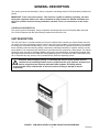
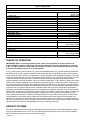
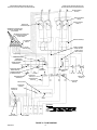
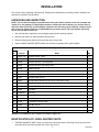
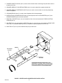
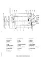
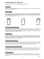

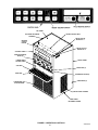
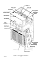
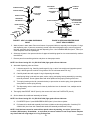
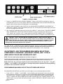
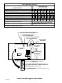
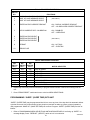
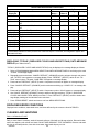
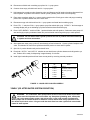
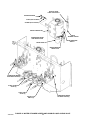
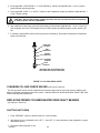
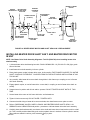
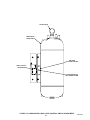
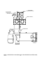
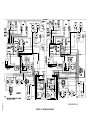


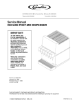
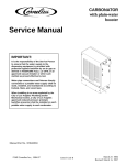
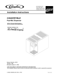
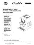


![Service Manual VA13 Carbonator [ 002818 ]](http://vs1.manualzilla.com/store/data/006013608_1-0f8f87056a0ab013b1dd01dac3912d47-150x150.png)