1
FCB OVERCOUNTER POST-MIX DISPENSER Service Manual WITH V3+FEATURES IMPORTANT: TO THE INSTALLER. It is the responsibility of the Installer to ensure that the water supply to the dispensing equipment is provided with protection against backflow by an air gap as defined in ANSI/ASME A112. 1.2-1979; or an approved vacuum breaker or other such method as proved effective by test. Water pipe connections and fixtures directly connected to a potable water supply shall be sized, installed, and maintained according to federal, state, and local laws. Part No. 2992 May 31, 1994 Revised: April 4, 1995 THIS DOCUMENT CONTAINS IMPORTANT INFORMATION This Manual must be read and understood before installing or operating this equipment IMI CORNELIUS INC; 1994–95 PRINTED IN U.S.A Part # Corrections/Update Document Unit Type/Model # FCB OC2 POST MIX DISPENSER W/V3+ Unit Part Numbers: 416136xxx 496136xxx Page Item Old Part Desc. New Part 71 53 2467 FOAM PACK 4467 72 66 326000000 COMPRESSOR 560004343 KIT 2HP 230V/60 Manual # 2992 Desc. FOAM PACK COMPRESSOR KIT 60H DOMESTIC 72 66 324233000 COMPRESSOR KIT 2HP 230/50 560004342 COMPRESSOR KIT 50H EXPORT 72 78 324120088 72 78 324120000 GEAR MOTOR 1/4HP 220V 2472 GEAR MOTOR 1/4HP 220/240V 50H KLAUBER GEAR MOTOR 1/4HP 240V/60 GEAR MOTOR KIT 230/50/60 EMERSON 72 78 3471 4689 72 78 2108 74 3 80 4 GEAR MOTOR 1/8HP 208/240 50/60H EMERSON 4210 MOTOR 1/4HP 220/240 50H FASCO 183412000 REGULATOR ASSY 100PSI N/A 324047000 BLENDER TANK 324194888 183412016 324205888 87 n/a 3232 GEAR MOTOR 230/50/60 EMERSON REGULATOR SECONDARY 100PSI BLENDER TANK FOR SINGLE FLOAT USE OR BLENDER TANK FOR DOUBLE FLOAT USE DRIVE SHAFT Agent Date Notes JLS 01/24/03 JLS 01/24/03 Includes all components and instructions to convert from R502 to R404. JLS 01/24/03 Includes all components and instructions to convert from R502 to R404. JLS 01/24/03 Klauber motor – for OC1 only JLS 01/24/03 Includes components and instructions to replace Klauber with Emerson motor JLS 01/24/03 Use Emerson motor 4689 when replacing an existing Emerson motor JLS 01/24/03 Obsolete JLS 01/24/03 JLS 01/24/03 JLS 01/24/03 PIN TABLE OF CONTENTS Page GENERAL DESCRIPTION . . . . . . . . . . . . . . . . . . . . . . . . . . . . . . . . . . . . . . . . . . . . . . . . . . 1 GENERAL DESCRIPTION . . . . . . . . . . . . . . . . . . . . . . . . . . . . . . . . . . . . . . . . . . . . . . 1 UNIT DESCRIPTION . . . . . . . . . . . . . . . . . . . . . . . . . . . . . . . . . . . . . . . . . . . . . . . . . . . 1 THEORY OF OPERATION . . . . . . . . . . . . . . . . . . . . . . . . . . . . . . . . . . . . . . . . . . . . . . 2 DEFROST SYSTEMS . . . . . . . . . . . . . . . . . . . . . . . . . . . . . . . . . . . . . . . . . . . . . . . . . . 3 MANUAL DEFROST SYSTEM . . . . . . . . . . . . . . . . . . . . . . . . . . . . . . . . . . . . . . 3 AUTOMATIC DEFROST SYSTEM . . . . . . . . . . . . . . . . . . . . . . . . . . . . . . . . . . . 3 ‘‘SLEEP’’ (SLEEP TIME) . . . . . . . . . . . . . . . . . . . . . . . . . . . . . . . . . . . . . . . . . . . . . . . . 4 ‘‘WAKE UP’’ (WAKE UP TIME) . . . . . . . . . . . . . . . . . . . . . . . . . . . . . . . . . . . . . . . . . . . 4 INSTALLATION . . . . . . . . . . . . . . . . . . . . . . . . . . . . . . . . . . . . . . . . . . . . . . . . . . . . . . . . . . . . 7 UNPACKING AND INSPECTION . . . . . . . . . . . . . . . . . . . . . . . . . . . . . . . . . . . . . . . . 7 IDENTIFICATION OF LOOSE-SHIPPED PARTS . . . . . . . . . . . . . . . . . . . . . . . . . . . 7 ELECTRICAL POWER REQUIREMENTS . . . . . . . . . . . . . . . . . . . . . . . . . . . . . . . . . 8 50 HZ UNIT . . . . . . . . . . . . . . . . . . . . . . . . . . . . . . . . . . . . . . . . . . . . . . . . . . . . . . . 8 60 HZ UNIT . . . . . . . . . . . . . . . . . . . . . . . . . . . . . . . . . . . . . . . . . . . . . . . . . . . . . . . 8 SELECTING LOCATION . . . . . . . . . . . . . . . . . . . . . . . . . . . . . . . . . . . . . . . . . . . . . . . . 8 INSTALLING UNIT . . . . . . . . . . . . . . . . . . . . . . . . . . . . . . . . . . . . . . . . . . . . . . . . . . . . . 9 INSTALLING LEVELING LEGS . . . . . . . . . . . . . . . . . . . . . . . . . . . . . . . . . . . . . . 9 INSTALLING DRIP TRAY SUPPORTS . . . . . . . . . . . . . . . . . . . . . . . . . . . . . . . 9 INSTALLING DRIP TRAY DRAIN HOSE KIT . . . . . . . . . . . . . . . . . . . . . . . . . . 9 PREPARING UNIT FOR CONNECTION TO SYRUP, CO2, AND CITY PLAIN WATER SOURCES . . . . . . . . . . . . . . . . . . . . . . . . . . . . . . . . . . . . . . . . . . 9 INSTALLING PRIMARY CO2 REGULATOR ASSEMBLY ON CO2 CYLINDER . . . . . . . . . . . . . . . . . . . . . . . . . . . . . . . . . . . . . . . . . . . . . . . . . . . . . . . 9 CONNECTING SOFT DRINK TANKS CO2 LINES TO PRIMARY CO2 REGULATOR ASSEMBLY . . . . . . . . . . . . . . . . . . . . . . . . . . . . . . . . . . . . . . . . . . 11 PREPARING UNIT SYRUP INLET LINES FOR CONNECTION TO SOFT DRINK TANKS . . . . . . . . . . . . . . . . . . . . . . . . . . . . . . . . . . . . . . . . . . . . . . . . . . . . 12 CONNECTING CO2 SOURCE LINE TO UNIT CO2 INLET LINE . . . . . . . . . 12 CONNECTING CITY PLAIN WATER SOURCE LINE TO UNIT . . . . . . . . . . 12 CONNECTING ELECTRICAL POWER CIRCUIT TO THE UNIT . . . . . . . . . 12 PREPARATION FOR OPERATION . . . . . . . . . . . . . . . . . . . . . . . . . . . . . . . . . . . . . . . 13 TURNING ON ELECTRICAL POWER TO UNIT . . . . . . . . . . . . . . . . . . . . . . . 13 TURNING ON CO2 SUPPLY TO THE UNIT . . . . . . . . . . . . . . . . . . . . . . . . . . . 13 ADJUSTING PRIMARY CO2 REGULATOR . . . . . . . . . . . . . . . . . . . . . . . . . . . 13 ADJUSTING PRODUCT BLENDER TANKS SECONDARY CO2 . . . . . . . . . 13 ADJUSTING CARBONATOR SECONDARY CO2 REGULATOR . . . . . . . . . 13 STARTING FCB AND ADJUSTING WATER-TO-SYRUP “RATIO” (BRIX) OF DISPENSED PRODUCT . . . . . . . . . . . . . . . . . . . . . . . . . . . . . . . . . . . . . . . . . . . 14 FILLING FREEZE CYLINDERS WITH PRODUCT . . . . . . . . . . . . . . . . . . . . . 15 CHECKING UNIT FOR SYRUP, CO2, OR PLAIN WATER LEAKS . . . . . . . 15 PLACING UNIT IN OPERATING LOCATION . . . . . . . . . . . . . . . . . . . . . . . . . . 16 ADJUSTING BEATER MOTOR CURRENT (EITHER SIDE) . . . . . . . . . . . . . 16 i 2992 TABLE OF CONTENTS (cont’d) Page ADJUSTMENT AND PROGRAMMING MAIN MENU SELECTIONS, COMPONENTS “DIAGNOSE’’ (DIAGNOSTIC MODE), AND (‘‘TOTALS” DISPLAYED CYCLES AND HOURS TOTALS) INTO UNIT . . . . . . . . . . . . . . . . . . . . . . . . . . . . . . . . . . . . . . 17 PROGRAMMING MAIN MENU SELECTION ONTO MESSAGE DISPLAY 17 SETTING CLOCK (TIME OF DAY) . . . . . . . . . . . . . . . . . . . . . . . . . . . . . . . . . . . 17 PROGRAMMING ‘‘DEFROST’’ (AUTOMATIC) SETTINGS INTO UNIT . . . 18 PROGRAMMING ‘‘SLEEP’’ (SLEEP TIME) INTO UNIT . . . . . . . . . . . . . . . . . 19 PROGRAMMING ‘‘WAKE UP’’ (WAKE UP TIME) INTO UNIT . . . . . . . . . . . . 19 PROGRAMMING POINT OF SALE MESSAGE DISPLAY . . . . . . . . . . . . . . . 22 ADJUSTING “VIS SET” (PRODUCT VISCOSITY) OF DISPENSED PRODUCT . . . . . . . . . . . . . . . . . . . . . . . . . . . . . . . . . . . . . . . . . . . . . . . . . . . . . . . . 22 ‘‘VIS READ’’ (ACTUAL VISCOSITY READOUT) OF PRODUCT IN FREEZE CYLINDERS . . . . . . . . . . . . . . . . . . . . . . . . . . . . . . . . . . . . . . . . . . . . . . 22 DISPLAYED EVAPORATOR REFRIGERATION COILS INLETS AND COMMON OUTLET SENSORS TEMPERATURES. . . . . . . . . . . . . . . . . . . . . 22 ‘‘VOLTAGE’’ (DISPLAYED VOLTAGE READOUT) . . . . . . . . . . . . . . . . . . . . . . 23 PROGRAMMING COMPONENTS ‘‘DIAGNOSE’’ (DIAGNOSTIC MODE) INTO UNIT . . . . . . . . . . . . . . . . . . . . . . . . . . . . . . . . . . . . . . . . . . . . . . . . . . . . . . . 23 DISPLAYING ‘‘TOTALS’’ (DISPLAYED CYCLES AND HOURS TOTALS) ONTO MESSAGE DISPLAY . . . . . . . . . . . . . . . . . . . . . . . . . . . . . . . . . . . . . . . . 26 PROGRAMMING FREEZE CYLINDERS BEATER “MOTORS” INTO UNIT ELECTRONICS . . . . . . . . . . . . . . . . . . . . . . . . . . . . . . . . . . . . . . . . . . . . . . 26 PROGRAMMING PROPER REFRIGERANT TYPE INTO UNIT ELECTRONICS . . . . . . . . . . . . . . . . . . . . . . . . . . . . . . . . . . . . . . . . . . . . . . . . . . . 27 DISPLAYED ERROR CONDITIONS . . . . . . . . . . . . . . . . . . . . . . . . . . . . . . . . . 27 OPERATOR’S INSTRUCTIONS . . . . . . . . . . . . . . . . . . . . . . . . . . . . . . . . . . . . . . . . . . . . . 29 CONTROL PANEL ASS’Y SWITCHES AND DISPLAYED MESSAGES . . . . . . . 29 CONTROL PANEL ASS’Y SWITCHES . . . . . . . . . . . . . . . . . . . . . . . . . . . . . . . 29 CONTROL PANEL ASSEMBLY DISPLAY MESSAGES . . . . . . . . . . . . . . . . . 30 FREEZE CYLINDERS MANUAL OR AUTOMATIC DEFROST SYSTEMS . . . . . 31 MANUAL DEFROST SYSTEM . . . . . . . . . . . . . . . . . . . . . . . . . . . . . . . . . . . . . . 31 AUTOMATIC DEFROST SYSTEM . . . . . . . . . . . . . . . . . . . . . . . . . . . . . . . . . . . 31 ‘‘SLEEP’’ (SLEEP TIME) OPERATION . . . . . . . . . . . . . . . . . . . . . . . . . . . . . . . . . . . . 31 ‘‘WAKE UP’’ (WAKE UP TIME) . . . . . . . . . . . . . . . . . . . . . . . . . . . . . . . . . . . . . . . . . . . 32 FACEPLATE RELIEF VALVES . . . . . . . . . . . . . . . . . . . . . . . . . . . . . . . . . . . . . . . . . . . 32 PRODUCT SAMPLE VALVES . . . . . . . . . . . . . . . . . . . . . . . . . . . . . . . . . . . . . . . . . . . 32 PRODUCT SHUTOFF VALVES . . . . . . . . . . . . . . . . . . . . . . . . . . . . . . . . . . . . . . . . . . 32 PRIMARY CO2 REGULATOR . . . . . . . . . . . . . . . . . . . . . . . . . . . . . . . . . . . . . . . . . . . 32 SECONDARY CO2 REGULATORS . . . . . . . . . . . . . . . . . . . . . . . . . . . . . . . . . . . . . . 32 CARBONATED WATER FLOW REGULATORS . . . . . . . . . . . . . . . . . . . . . . . . . . . . 32 SYRUP FLOW REGULATORS . . . . . . . . . . . . . . . . . . . . . . . . . . . . . . . . . . . . . . . . . . 32 DISPENSING VALVES . . . . . . . . . . . . . . . . . . . . . . . . . . . . . . . . . . . . . . . . . . . . . . . . . 32 DISPENSED PRODUCT CONDITIONS . . . . . . . . . . . . . . . . . . . . . . . . . . . . . . . . . . . 33 ‘‘OVERRUN’’, AS APPLIED TO FROZEN CARBONATED BEVERAGES . . 33 OPERATING CHARACTERISTICS . . . . . . . . . . . . . . . . . . . . . . . . . . . . . . . . . . . . . . . 34 OPERATING UNIT . . . . . . . . . . . . . . . . . . . . . . . . . . . . . . . . . . . . . . . . . . . . . . . . . . . . . 34 2992 ii TABLE OF CONTENTS (cont’d) Page REPLENISHING SYRUP SUPPLY . . . . . . . . . . . . . . . . . . . . . . . . . . . . . . . . . . . . . . . 34 PRODUCT FLAVOR CHANGE . . . . . . . . . . . . . . . . . . . . . . . . . . . . . . . . . . . . . . . . . . 35 CHECKING CO2 SUPPLY . . . . . . . . . . . . . . . . . . . . . . . . . . . . . . . . . . . . . . . . . . . . . . 35 CLEANING AND SANITIZING . . . . . . . . . . . . . . . . . . . . . . . . . . . . . . . . . . . . . . . . . . . 35 DAILY CLEANING . . . . . . . . . . . . . . . . . . . . . . . . . . . . . . . . . . . . . . . . . . . . . . . . . 35 SANITIZING . . . . . . . . . . . . . . . . . . . . . . . . . . . . . . . . . . . . . . . . . . . . . . . . . . . . . . 35 CLEANING CONDENSER COIL . . . . . . . . . . . . . . . . . . . . . . . . . . . . . . . . . . . . . . . . . 35 LUBRICATION . . . . . . . . . . . . . . . . . . . . . . . . . . . . . . . . . . . . . . . . . . . . . . . . . . . . . . . . 35 ADJUSTMENTS . . . . . . . . . . . . . . . . . . . . . . . . . . . . . . . . . . . . . . . . . . . . . . . . . . . . . . . 35 CARBONATED WATER FLOW RATE . . . . . . . . . . . . . . . . . . . . . . . . . . . . . . . . 35 WATER-TO-SYRUP “RATIO” (BRIX) OF DISPENSED PRODUCT . . . . . . . 36 CO2 REGULATORS . . . . . . . . . . . . . . . . . . . . . . . . . . . . . . . . . . . . . . . . . . . . . . . 36 ADJUSTING BEATERS MOTORS CURRENTS . . . . . . . . . . . . . . . . . . . . . . . 36 PROGRAMMING MAIN MENU SELECTIONS ONTO MESSAGE DISPLAY 36 SETTING ‘‘CLOCK’’ (TIME OF DAY) . . . . . . . . . . . . . . . . . . . . . . . . . . . . . . . . . 36 PROGRAMMING ‘‘DEFROST’’ (AUTOMATIC) SETTINGS INTO UNIT . . 36 PROGRAMMING ‘‘SLEEP’’ (SLEEP TIME) INTO UNIT . . . . . . . . . . . . . . . . . 36 PROGRAMMING ‘‘WAKE UP’’ (WAKE UP) TIME INTO UNIT . . . . . . . . . . . . 37 PROGRAMMING POINT OF SALE MESSAGE DISPLAY . . . . . . . . . . . . . . . 37 ADJUSTING ‘‘VIS SET’’ (PRODUCT VISCOSITY) OF DISPENSED PRODUCT . . . . . . . . . . . . . . . . . . . . . . . . . . . . . . . . . . . . . . . . . . . . . . . . . . . . . . . . 37 DISPLAYED EVAPORATOR REFRIGERATION COILS INLETS AND COMMON OUTLET SENSORS TEMPERATURES . . . . . . . . . . . . . . . . . . . . 37 ‘‘VOLTAGE’’ (DISPLAYED VOLTAGE READOUT) . . . . . . . . . . . . . . . . . . . . . . 37 PROGRAMMING COMPONENTS ‘‘DIAGNOSE’’ (DIAGNOSTIC MODE) INTO UNIT . . . . . . . . . . . . . . . . . . . . . . . . . . . . . . . . . . . . . . . . . . . . . . . . . . . . . . . 37 DISPLAYING ‘‘TOTALS’’ (DISPLAYED CYCLES AND HOURS TOTALS) ONTO MESSAGE DISPLAY . . . . . . . . . . . . . . . . . . . . . . . . . . . . . . . . . . . . . . . . 37 PROGRAMMING PROPER REFRIGERANT TYPE INTO UNIT ELECTRONICS . . . . . . . . . . . . . . . . . . . . . . . . . . . . . . . . . . . . . . . . . . . . . . . . . . . 37 DISPLAYED ERROR CONDITIONS . . . . . . . . . . . . . . . . . . . . . . . . . . . . . . . . . 37 WATER STRAINER SCREEN AND DOUBLE LIQUID CHECK VALVE MAINTENANCE . . . . . . . . . . . . . . . . . . . . . . . . . . . . . . . . . . . . . . . . . . . . . . . . . . . . . . . 38 CLEANING CO2 GAS CHECK VALVES . . . . . . . . . . . . . . . . . . . . . . . . . . . . . . 38 SERVICE AND MAINTENANCE . . . . . . . . . . . . . . . . . . . . . . . . . . . . . . . . . . . . . . . . . . . . . 39 PREPARING UNIT FOR SHIPPING, STORING, OR RELOCATING . . . . . . . . . . 39 PERIODIC INSPECTION . . . . . . . . . . . . . . . . . . . . . . . . . . . . . . . . . . . . . . . . . . . . . . . 39 REMOVAL OF TOP PANEL, BACK PANEL, SIDE PANELS, AND FRONT ACCESS PANEL . . . . . . . . . . . . . . . . . . . . . . . . . . . . . . . . . . . . . . . . . . . . . . . . . . . . . . . 39 TOP PANEL . . . . . . . . . . . . . . . . . . . . . . . . . . . . . . . . . . . . . . . . . . . . . . . . . . . . . . 39 BACK PANEL . . . . . . . . . . . . . . . . . . . . . . . . . . . . . . . . . . . . . . . . . . . . . . . . . . . . . 39 SIDE PANELS . . . . . . . . . . . . . . . . . . . . . . . . . . . . . . . . . . . . . . . . . . . . . . . . . . . . 39 FRONT ACCESS PANEL . . . . . . . . . . . . . . . . . . . . . . . . . . . . . . . . . . . . . . . . . . 42 OPENING AND CLOSING FRONT ACCESS DOOR . . . . . . . . . . . . . . . . . . . . . . . 42 OPENING FRONT ACCESS DOOR . . . . . . . . . . . . . . . . . . . . . . . . . . . . . . . . . 42 CLOSING FRONT ACCESS DOOR . . . . . . . . . . . . . . . . . . . . . . . . . . . . . . . . . . 42 iii 2992 TABLE OF CONTENTS (cont’d) Page LUBRICATION . . . . . . . . . . . . . . . . . . . . . . . . . . . . . . . . . . . . . . . . . . . . . . . . . . . . . . . . 42 CARBONATOR WATER PUMP MOTOR . . . . . . . . . . . . . . . . . . . . . . . . . . . . . . 42 SERVICING DISPENSING VALVES CAGED O-RINGS AND FREEZE CYLINDERS DRIVE SHAFT/ SEAL ASSEMBLIES . . . . . . . . . . . . . . . . . . . . . 42 CLEANING CONDENSER COIL . . . . . . . . . . . . . . . . . . . . . . . . . . . . . . . . . . . . . . . . . 45 ADJUSTMENTS . . . . . . . . . . . . . . . . . . . . . . . . . . . . . . . . . . . . . . . . . . . . . . . . . . . . . . . 45 ADJUSTING PLAIN WATER PRESSURE REGULATOR . . . . . . . . . . . . . . . . 45 ADJUSTING CARBONATED WATER FLOW RATE . . . . . . . . . . . . . . . . . . . . 45 ADJUSTING CO2 REGULATORS . . . . . . . . . . . . . . . . . . . . . . . . . . . . . . . . . . . 46 ADJUSTING BRIX (WATER-TO-SYRUP) ‘‘RATIO’’ OF DISPENSED PRODUCT . . . . . . . . . . . . . . . . . . . . . . . . . . . . . . . . . . . . . . . . . . . . . . . . . . . . . . . . 47 PRODUCT CARBONATION ADJUSTMENT . . . . . . . . . . . . . . . . . . . . . . . . . . 48 CLEANING AND SANITIZING . . . . . . . . . . . . . . . . . . . . . . . . . . . . . . . . . . . . . . . . . . . 48 DAILY CLEANING OF UNIT . . . . . . . . . . . . . . . . . . . . . . . . . . . . . . . . . . . . . . . . 48 SANITIZING SYRUP SYSTEMS . . . . . . . . . . . . . . . . . . . . . . . . . . . . . . . . . . . . . 49 YEARLY OR AFTER WATER SYSTEM DISRUPTION . . . . . . . . . . . . . . . . . . . . . . 51 SERVICING CARBONATOR WATER PUMP WATER STRAINER SCREEN . . . . . . . . . . . . . . . . . . . . . . . . . . . . . . . . . . . . . . . . . . . . . . . . . . . . . . . . . 51 SERVICING CARBONATOR WATER PUMP DOUBLE LIQUID CHECK VALVE . . . . . . . . . . . . . . . . . . . . . . . . . . . . . . . . . . . . . . . . . . . . . . . . . . . . . . . . . . . 52 REPLENISHING SYRUP SUPPLY . . . . . . . . . . . . . . . . . . . . . . . . . . . . . . . . . . . . . . . 53 REPLENISHING CO2 SUPPLY . . . . . . . . . . . . . . . . . . . . . . . . . . . . . . . . . . . . . . . . . . 54 SYRUP FLAVOR CHANGE . . . . . . . . . . . . . . . . . . . . . . . . . . . . . . . . . . . . . . . . . . . . . 54 CLEANING CO2 GAS CHECK VALVES . . . . . . . . . . . . . . . . . . . . . . . . . . . . . . 56 REPLACING FREEZE CYLINDER BEATER DRIVE MOTOR . . . . . . . . . . . . . . . . 57 ADJUSTING CARBONATOR TANK LIQUID LEVEL . . . . . . . . . . . . . . . . . . . . . . . . 57 TROUBLESHOOTING . . . . . . . . . . . . . . . . . . . . . . . . . . . . . . . . . . . . . . . . . . . . . . . . . . . . . . 63 TROUBLESHOOTING CONTROL PANEL SWITCHES AND FAULT MESSAGES . . . . . . . . . . . . . . . . . . . . . . . . . . . . . . . . . . . . . . . . . . . . . . . . . . . . . . . . . . 63 ONE OR MORE CONTROL PANEL SWITCHES NOT OPERATING. . . . . . 63 ALL CONTROL PANEL SWITCHES NOT OPERATING. . . . . . . . . . . . . . . . . 63 CONTROL PANEL SWITCHES CANNOT BE DEACTIVATED. . . . . . . . . . . 64 PARTIAL MESSAGE OR DULL (POORLY ILLUMINATED) DISPLAY. . . . . . 64 ONE OR MORE FAULT MESSAGES NOT OPERATING. . . . . . . . . . . . . . . . 64 ALL FAULT MESSAGES NOT OPERATING. . . . . . . . . . . . . . . . . . . . . . . . . . . 64 ‘‘CO2 OUT’’ FAULT MESSAGE GOES ON DURING OPERATION. . . . . . . . 65 ‘‘H2O OUT’’ FAULT MESSAGE GOES ON DURING OPERATION. . . . . . . . 65 ‘‘SYRUP 1’’ OR ‘‘SYRUP 2’’ FAULT MESSAGE GOES ON DURING OPERATION. . . . . . . . . . . . . . . . . . . . . . . . . . . . . . . . . . . . . . . . . . . . . . . . . . . . . . 65 ‘‘ERROR 1’’ OR ‘‘ERROR 2’’ FAULT MESSAGE GOES ON DURING OPERATION. . . . . . . . . . . . . . . . . . . . . . . . . . . . . . . . . . . . . . . . . . . . . . . . . . . . . . 65 FREEZE CYLINDER AUTOMATIC DEFROST CYCLE DOES NOT OPERATE. . . . . . . . . . . . . . . . . . . . . . . . . . . . . . . . . . . . . . . . . . . . . . . . . . . . . . . . 65 UNIT DOES NOT GO OFF AUTOMATIC DEFROST CYCLE. . . . . . . . . . . . 65 MANUAL DEFROST CYCLE DOES NOT OPERATE WHEN ‘‘DEFROST’’ SWITCH IS PRESSED. . . . . . . . . . . . . . . . . . . . . . . . . . . . . . . . . . . . . . . . . . . . . 65 2992 iv TABLE OF CONTENTS (cont’d) Page DEFROST CYCLE DOES NOT CANCEL AFTER PRESSING ‘‘CANCEL DEFROST ’’ SWITCH. . . . . . . . . . . . . . . . . . . . . . . . . . . . . . . . . . . . . . . . . . . . . . 66 TROUBLESHOOTING PRODUCT BLENDER TANKS AND CARBONATOR . . . 66 CARBONATOR WATER PUMP MOTOR WILL NOT OPERATE. . . . . . . . . . 66 CARBONATOR WATER PUMP WILL NOT SHUT OFF. . . . . . . . . . . . . . . . . . 66 ERRATIC CARBONATOR WATER PUMP CYCLING. . . . . . . . . . . . . . . . . . . 66 TROUBLESHOOTING DISPENSED PRODUCT . . . . . . . . . . . . . . . . . . . . . . . . . . . 67 BRIX (WATER–TO–SYRUP) ‘‘RATIO’’ TOO LOW. . . . . . . . . . . . . . . . . . . . . . 67 BRIX (WATER-TO-SYRUP) ‘‘RATIO’’ TOO HIGH. . . . . . . . . . . . . . . . . . . . . . . 67 IMPROPER PRODUCT DISPENSED. . . . . . . . . . . . . . . . . . . . . . . . . . . . . . . . . 67 PRODUCT WILL NOT DISPENSE OUT OF DISPENSING VALVE, IN ONLY SMALL AMOUNTS, OR ONLY LIQUID. . . . . . . . . . . . . . . . . . . . . . . . . . . . . . . . 67 FREEZE CYLINDER DOES NOT REFILL AT ALL TIMES WHEN DISPENSING. . . . . . . . . . . . . . . . . . . . . . . . . . . . . . . . . . . . . . . . . . . . . . . . . . . . . . 67 FROZEN PRODUCT CONSISTENCY VARIES EXCESSIVELY. . . . . . . . . . 67 CYLINDER FREEZE-UP. . . . . . . . . . . . . . . . . . . . . . . . . . . . . . . . . . . . . . . . . . . . 68 WARRANTY . . . . . . . . . . . . . . . . . . . . . . . . . . . . . . . . . . . . . . . . . . . . . . . . . . . . . . . . . . . . . . 88 LIST OF FIGURES FIGURE 1. FCB OVERCOUNTER POST-MIX DISPENSER . . . . . . . . . . . . . . . . . 1 FIGURE 2. FLOW DIAGRAM . . . . . . . . . . . . . . . . . . . . . . . . . . . . . . . . . . . . . . . . . . . . 5 FIGURE 3. FREEZE CYLINDER CUTAWAY VIEW . . . . . . . . . . . . . . . . . . . . . . . . . 10 FIGURE 4. BEATERS AND SCRAPER BLADES INSTALLATION . . . . . . . . . . . . 11 FIGURE 5. CONTROL PANEL ASS’Y . . . . . . . . . . . . . . . . . . . . . . . . . . . . . . . . . . . . 15 FIGURE 6. MASTER AND RELAY CIRCUIT BOARD . . . . . . . . . . . . . . . . . . . . . . . 21 FIGURE 7. OPERATING CONTROLS . . . . . . . . . . . . . . . . . . . . . . . . . . . . . . . . . . . . 40 FIGURE 8. UNIT INTERNAL COMPONENTS . . . . . . . . . . . . . . . . . . . . . . . . . . . . . 41 FIGURE 9. SELF-CLOSING DISPENSING VALVE . . . . . . . . . . . . . . . . . . . . . . . . . 43 FIGURE 10. LIQUID CHECK VALVE ASSEMBLY . . . . . . . . . . . . . . . . . . . . . . . . . . 52 FIGURE 11. WATER STRAINER SCREEN AND DOUBLE LIQUID CHECK VALVE . . . . . . . . . . . . . . . . . . . . . . . . . . . . . . . . . . . . . . . . . . . . . . . . . . . . . . . . . . . . . . . . 55 FIGURE 12. CO2 GAS CHECK VALVE . . . . . . . . . . . . . . . . . . . . . . . . . . . . . . . . . . . 56 FIGURE 13. SERVICING BEATER MOTOR DRIVE SHAFT/SEAL ASSEMBLY 59 FIGURE 14. CARBONATOR LIQUID LEVEL CONTROL SWITCH ADJUSTMENT . . . . . . . . . . . . . . . . . . . . . . . . . . . . . . . . . . . . . . . . . . . . . . . . . . . . . . . . 60 FIGURE 15. REFRIGERATION FLOW DIAGRAM . . . . . . . . . . . . . . . . . . . . . . . . . . 61 FIGURE 16. WIRING DIAGRAM . . . . . . . . . . . . . . . . . . . . . . . . . . . . . . . . . . . . . . . . . 62 FIGURE 17. OVERCOUNTER FCB POST-MIX DISPENSER . . . . . . . . . . . . . . . . 70 FIGURE 18. SECONDARY CO2 REGULATOR COMPONENTS . . . . . . . . . . . . . 73 FIGURE 19. CONTROL BOX COMPONENTS . . . . . . . . . . . . . . . . . . . . . . . . . . . . . 73 FIGURE 20. SECONDARY CO2 REGULATOR ASS’Y . . . . . . . . . . . . . . . . . . . . . . 74 FIGURE 21. TUBE ASSEMBLY . . . . . . . . . . . . . . . . . . . . . . . . . . . . . . . . . . . . . . . . . . 74 FIGURE 22. TUBE ASSEMBLY . . . . . . . . . . . . . . . . . . . . . . . . . . . . . . . . . . . . . . . . . . 74 FIGURE 23. CO2 REGULATOR ASSEMBLY . . . . . . . . . . . . . . . . . . . . . . . . . . . . . . 75 FIGURE 24. CHECK VALVE ASSEMBLY . . . . . . . . . . . . . . . . . . . . . . . . . . . . . . . . . 75 v 2992 TABLE OF CONTENTS (cont’d) Page LIST OF FIGURES(CONT’D) FIGURE 25. BLENDER AND TUBING COMPONENTS . . . . . . . . . . . . . . . . . . . . . 76 FIGURE 26. TUBING ASSEMBLY (CARB WATER) . . . . . . . . . . . . . . . . . . . . . . . . 77 FIGURE 27. TUBING ASSEMBLY (SYRUP) . . . . . . . . . . . . . . . . . . . . . . . . . . . . . . . 77 FIGURE 28. TUBING ASSEMBLY (BLENDER TO FREEZE CYLINDER) . . . . . . 77 FIGURE 29. TUBING ASSEMBLY (WATER SOLENOID TO BLENDER) . . . . . . 78 FIGURE 30. TUBING ASSEMBLY (REGULATOR TO BLENDER) . . . . . . . . . . . . 78 FIGURE 31. DOUBLE CHECK VALVE ASSEMBLY . . . . . . . . . . . . . . . . . . . . . . . . . 78 FIGURE 32. SOLENOID VALVE ASSEMBLY . . . . . . . . . . . . . . . . . . . . . . . . . . . . . . 79 FIGURE 33. BLENDER COMPONENTS . . . . . . . . . . . . . . . . . . . . . . . . . . . . . . . . . . 80 FIGURE 34. CONTROL BOX AND DISPLAY PANEL COMPONENTS . . . . . . . . 81 FIGURE 35. FACEPLATE ASSEMBLY . . . . . . . . . . . . . . . . . . . . . . . . . . . . . . . . . . . . 82 FIGURE 36. DISPENSING VALVE ASSEMBLY . . . . . . . . . . . . . . . . . . . . . . . . . . . . 83 FIGURE 37. CARBONATOR COMPONENTS . . . . . . . . . . . . . . . . . . . . . . . . . . . . . 84 FIGURE 38. TUBING ASSEMBLY . . . . . . . . . . . . . . . . . . . . . . . . . . . . . . . . . . . . . . . 84 FIGURE 39. DRIP TRAY DRAIN KIT . . . . . . . . . . . . . . . . . . . . . . . . . . . . . . . . . . . . . 84 FIGURE 40. CARBONATOR TANK AND LINKAGE ASSEMBLY . . . . . . . . . . . . . 85 FIGURE 41. PUMP AND MOTOR ASS’Y . . . . . . . . . . . . . . . . . . . . . . . . . . . . . . . . . 86 FIGURE 42. BEATER MOTOR DRIVE SHAFT/SEAL ASS’Y . . . . . . . . . . . . . . . . . 87 LIST OF TABLES TABLE 1. DESIGN DATA . . . . . . . . . . . . . . . . . . . . . . . . . . . . . . . . . . . . . . . . . . . . . . . 2 TABLE 2. ACCESSORIES AND TOOLS . . . . . . . . . . . . . . . . . . . . . . . . . . . . . . . . . . 3 TABLE 3. LOOSE-SHIPPED PARTS . . . . . . . . . . . . . . . . . . . . . . . . . . . . . . . . . . . . . 7 TABLE 4. MAIN MENU SELECTIONS . . . . . . . . . . . . . . . . . . . . . . . . . . . . . . . . . . . . 18 TABLE 5. DIP SWITCH FUNCTIONS . . . . . . . . . . . . . . . . . . . . . . . . . . . . . . . . . . . . . 20 TABLE 6. MOTOR SELECT . . . . . . . . . . . . . . . . . . . . . . . . . . . . . . . . . . . . . . . . . . . . . 20 TABLE 7. POINT OF SALE DISPLAY MESSAGES . . . . . . . . . . . . . . . . . . . . . . . . 20 TABLE 8. “TOTALS” (DISPLAYED CYCLES AND HOURS TOTALS) MENU . . . 24 TABLE 9. DISPLAYED ERROR CONDITIONS . . . . . . . . . . . . . . . . . . . . . . . . . . . . . 25 2992 vi GENERAL DESCRIPTION IMPORTANT: To the user of this manual – This manual is a guide for installing, operating, and maintaining this equipment. Refer to Table of Contents for page location of information pertaining to questions that arise during installation, operation, service and maintenance, or troubleshooting this equipment. Warranty Registration Date (to be filled out by customer) Model Number: Serial Number: Install Date: Local Authorized Service Center: GENERAL DESCRIPTION This section gives the description, theory of operation, and design data for the FCB (Frozen Carbonated Beverage) Overcounter Post-Mix Dispenser with V3+ Features (hereafter referred to as a Unit). UNIT DESCRIPTION The Unit (see Figure 1) consists basically of two freeze cylinders, each containing an internal beater driven by an electric motor, one refrigeration system with a 2-horsepower compressor, one carbonator which feeds both carbonator-blender tanks, a timer-controlled automatic hot-gas defrost system to defrost the freeze cylinders, and interconnecting tubing, components, and fittings necessary to regulate, transfer, and dispense the product. The components are attached to a steel frame and are enclosed in a steel cabinet. The cabinet sides and back panels are easily removed and the front access door may be opened to facilitate installation and service and maintenance. A transparent faceplate, with an integral relief valve and a removable self-closing dispensing valve, is mounted on front of each freeze cylinder. A drip tray, with cup rest, is located directly below the dispensing valves. FIGURE 1. FCB OVERCOUNTER POST-MIX DISPENSER CAUTION: Before shipping, storing, or relocating Unit, syrup systems must be sanitized and all sanitizing solution must be purged from syrup systems. All water must also be purged from plain and carbonated water systems. A freezing ambient environment will cause residual sanitizing solution or water remaining inside Unit to freeze resulting in damage to internal components. 1 2992 Table 1. Design Data Unit Part Numbers: 60 HZ Unit 50 HZ Unit 416136XXX 496136XXX Overall Dimensions: Height Width Depth W/O Drip tray Depth W/Drip Tray 32 inches 19 inches 31 1/8 inches 36 inches Shipping Weight (approx) 420 pounds Refrigeration System: Compressor Horsepower Refrigerant Type And Charge 2 H.P. See Unit Nameplate Ambient Operating Temperature 40° F to 100° F Electrical Requirements: Operating Voltage See Unit Nameplate See Unit Nameplate Operating Current THEORY OF OPERATION (see Figure 2) A CO2 cylinder delivers carbon dioxide (CO2) gas to an adjustable primary CO2 regulator assembly which is attached to the cylinder. The primary CO2 regulator assembly in turn delivers CO2 gas to adjustable secondary CO2 regulators inside the Unit and also to two soft drink tanks. CO2 is delivered from the adjustable secondary CO2 regulators to the carbonator tank and also to product-blender tanks inside the Unit. CO2 gas pressure pushes syrup out of the soft drink tanks through the syrup sold-out switches, through adjustable syrup flow regulators, through electrically operated syrup solenoid valves, and on to the product blender tanks. At the same time, plain water passes through the water pressure regulator and is pumped into the carbonated water tank by the water pump and is carbonated by CO2 gas pressure also entering the tank. Carbonated water is pushed by CO2 gas pressure from the carbonated water tank, through adjustable carbonated water flow regulators, through electrically operated carbonated water solenoid valves, and on to the product blender tanks. Carbonated water and syrup enter the tanks properly proportioned (blended) for desired BRIX of dispensed product by adjustment of the syrup flow regulators. From product blender tanks, product is pushed by the CO2 gas into the freeze cylinders. The beater in each freeze cylinder is driven by an electric motor. Scraper blades, attached to the beaters, scrape product from the cylinder walls as product enters the freeze cylinders and is frozen. Transparent faceplate, attached to the front of each freeze cylinder, includes a self-closing dispensing valve and a spring-loaded relief valve that protects freeze cylinder from accidental over pressure. The relief valve is also used to bleed CO2 gas pressure from the freeze cylinder to the atmosphere when filling the cylinder with product. Electronic sensing on each freeze cylinder motor provides a means of adjusting viscosity (consistency) of the dispensed product to suit customer preference. 2992 2 Table 2. Accessories and Tools ACCESSORIES Installation Kits 1155 Cup Holder 511005000 Cup Holder 511006000 CO2 Changeover Kit 511035000 GENERIC FLAVOR TABS Cola 1085 Cherry 1086 Orange 1087 Grape 1088 Lemon-Lime 1089 Strawberry 1090 Banana 1091 SERVICE TOOLS 3-gallon Sanitizing Tank 281884000 Spanner Wrench, Dispensing Valve 322859000 Refractometer, 0-30 Scale 511004000 Wrench, Rear Seal Housing 2899 Tool, Drive/Coupler Adjustment Gauge 3810 DEFROST SYSTEMS The Unit is equipped with both manual and automatic hot-gas defrost systems. The automatic defrost system may be programmed into the Unit to occur up to nine different times a day with a minimum of two hours between defrost time settings or the system may be completely turned off. MANUAL DEFROST SYSTEM The Manual hot-gas defrost system may be activated at any time by pressing the ‘‘DEFROST’’ switch on front of the Unit. Refrigeration compressor will operate for a short time, then both freeze cylinders will go into defrost and defrost for approximately 60 seconds. At the end of the manual defrost cycle, the Unit will return to normal operation. Manual defrost may be cancelled at any time by pressing the ‘‘CANCEL DEFROST’’ switch. AUTOMATIC DEFROST SYSTEM The automatic hot-gas defrost system may be programmed into the Unit to occur up to nine different times a day with a minimum of two hours between defrost settings. At the start of each automatic defrost cycle, refrigeration compressor will operate for 30 seconds to pump freon out of the freeze cylinders evaporator coils. After freon has been pumped out of the freeze cylinders evaporator coils, No. 1 freeze cylinders only will go into defrost cycle and defrost for approximately 7 minutes, then will return to normal operation. This ends the automatic defrost cycle of No. 1 freeze cylinder. No. 2 freeze cylinder will defrost 30 minutes after the start of No. 1 freeze cylinder. The next automatic defrost cycle will occur according to the time programmed into the Unit. Automatic defrost may be cancelled at any time by pressing the ‘‘CANCEL DEFROST’’ switch. 3 2992 ‘‘SLEEP’’ (SLEEP TIME) ‘‘SLEEP’’ (SLEEP TIME) may be programmed into Unit to allow Unit to go into sleep time (Unit shut down, freeze cylinders beaters and refrigeration systems not operating). At start of sleep time, refrigeration compressor will operate for 30 seconds to pump freon out of freeze cylinders evaporator coils, then No. 1 freeze cylinder will go into defrost and defrost for 60 seconds. After No. 1 freeze cylinder has defrosted, No. 2 freeze cylinder will go into defrost and defrost for 60 seconds. At end of No. 2 freeze cylinder defrost, Unit will shut down and go into sleep time. ‘‘WAKE UP’’ (WAKE UP TIME) ‘‘WAKE UP’’ (WAKE UP TIME) may be programmed into the Unit to allow Unit to resume normal operation at a desired time. When programmed wake up time is reached, an alarm will sound for a short duration, then Unit will resume normal operation. NOTE: Automatic defrost, sleep time, and wake up time may be used in any combination together or separately. 2992 4 *WATER PRESSURE REGULATOR IS FACTORY ADJUSTED TO 45-PSI AND SHOULD NOT BE READJUSTED. PRODUCT SAMPLE VALVE(2) **SYRUP SOLD-OUT SWITCHES ARE FACTORY ADJUSTED AND SHOULD NOT BE READJUSTED. LINE LEGEND CO2 PLAIN WATER CARB WATER SYRUP PRODUCT CARBONATOR TANK PRODUCT BLENDER TANK(2) PRODUCT SHUTOFF VALVE(2) FREEZE CYLINDER(2) CARBONATED WATER VOLUME SAMPLE VALVE FREEZE CYLINDER OVERFLOW TUBE CARBONATED WATER SOLENOID VALVE(2) CARBONATED WATER FLOW REGULATOR(2) SYRUP SOLENOID VALVE(2) SYRUP FLOW REGULATOR(2) PRIMARY CO2 REGULATOR ASS’Y SYRUP SOLD-OUT FLOAT SWITCH(2) LIQUID CHECK VALVE(2) *WATER PRESSURE REGULATOR PLAIN WATER SOURCE SHUTOFF VALVE **SYRUP SOLD-OUT SWITCH DOUBLE LIQUID CHECK VALVE CO2 CHECK VALVE CO2 CYLINDER WATER PRESSURE SWITCH CARBONATOR WATER PUMP CO2 PRESSURE SWITCH SOFT DRINK TANK(2) CO2 CHECK VALVE(3) SECONDARY CO2 REGULATORS TO PRODUCT BLENDER TANKS (60–PSI GAGE) (2) SECONDARY CO2 REGULATOR TO CARBONATOR TANK (100-PSI GAGE) FIGURE 2. FLOW DIAGRAM 5 2992 THIS PAGE LEFT BLANK INTENTIONALLY 2992 6 INSTALLATION This section covers unpacking and inspection, installing LOOSE-SHIPPED PARTS, selecting location, installing Unit, preparing for operation, and operation. UNPACKING AND INSPECTION (see Figure 7) NOTE: The Unit was thoroughly inspected before leaving the factory and the carrier has accepted and signed for it. Any damage or irregularities should be noted at time of delivery (or not later than 15 days from date of delivery) and immediately reported to the delivering carrier. Request a written inspection report from Claims Inspector to substantiate any necessary claim. File claim with the delivering carrier, not with IMI Cornelius Inc. 1. After Unit has been unpacked, remove shipping tape and other packing material. 2. Remove Unit sides and back panels as instructed. 3. Remove shipping bolts that secure Unit to skid, then remove skid. 4. Unpack LOOSE-SHIPPED PARTS. Make sure all items are present and in good condition. Table 3. Loose-Shipped Parts Item No. Part No. 1 178025100 Tapered Gasket, White 4 2 322859000 Spanner Wrench, Dispensing Valve 1 3 325216000 Cleaning Brush 1 4 311304000 Tapered Gasket, Black 1 5 317660000 Cup Rest 1 6 325282000 Thread Cutting Screw, Hex Hd.; No. 8 by 18 by 1/2-in. long 2 7 2738 Drip Tray Support, Left 1 8 2739 Drip Tray Support, Right 1 9 317659029 Drip Tray 1 10 326002000 Kit, Drip Tray Drain Hose 1 11 2899 Wrench, Rear Seal Housing 1 12 3810 Tool, Drive/Coupler Adjustment Gauge 1 13 324252000 Leveling Leg 4 14 3247 Spacer, White 2 15 3221 Front Access Panel 1 16 3108 Thread Cutting Screw, Phil Pan Hd; No. 10 by 32 by 1-in. long 2 Name Qty. * Numbers in parentheses are in reference to items in Figure 3. IDENTIFICATION OF LOOSE-SHIPPED PARTS 1. TAPERED GASKETS, WHITE (item 1) are used to seal connections when connecting Unit product inlet lines to product tanks and connecting Unit CO2 inlet line to CO2 source. 7 2992 2. SPANNER WRENCH, DISPENSING VALVE (item 2) is used to remove shank nuts securing dispensing valves to faceplates. 3. CLEANING BRUSH (item 3) is used to clean faceplate relief valves passages. 4. TAPERED GASKET, BLACK (item 4) is used to seal connection when connecting plain water source line to Unit water inlet line. 5. DRIP TRAY SUPPORTS (item 7) and (item 8) to be installed on front of Unit (See Figure 7) and secured with Thread Cutting SCREWS (item 6) and THREAD CUTTING SCREWS (Item 18). 6. CUP REST (item 5) to be installed in DRIP TRAY (item 9), then drip tray to be installed on drip tray supports. 7. DRIP TRAY DRAIN HOSE KIT (item 10) to be installed on drip tray as instructed in Instructions provided in the Kit. 8. WRENCH, REAR SEAL HOUSING (item 11) used to remove the drive shaft/seal assembly from inside the freeze cylinder. 9. TOOL, DRIVE/COUPLER ADJUSTMENT GAUGE (item 12) is used for servicing the beater motor drive shaft/ seal assembly (See Figure 13). 10. LEVELING LEGS (item 13) are to be installed on bottom of the Unit. 11. FRONT ACCESS PANEL (item 15) to be installed on front of the Unit (See Figure 7) and secured with WHITE SPACERS (item 14) and SCREWS (item 16). SPACERS TO BE INSTALLED BETWEEN THE FRONT PANEL AND THE UNIT FRAME. ELECTRICAL POWER REQUIREMENTS IMPORTANT: Before connecting electrical power to the Unit, refer to nameplate and Note if Unit is to be operated with 50 or 60 Hz power source. 50 HZ UNIT IMPORTANT: Power circuit voltage across L1 and L2 terminals on contactor inside lower control box, with refrigeration compressor operating, must be in range of 209-253 VAC, 50Hz single-phase for proper operation. A properly grounded 209-253 VAC, 50Hz single-phase electrical circuit connected through a 30-amp minimumrated disconnect switch (not provided) fused at 30-amps (slow-blow) must be available to be connected to the electrical box located in the lower back side of the Unit. 60 HZ UNIT IMPORTANT: Power circuit voltage across L1 and L2 terminals on contactor inside lower electrical control box, with refrigeration compressor operating, must be in range of 198-253 VAC, 60 Hz single-phase for proper operation. A properly grounded 198-253 VAC, 60Hz single-phase electrical circuit connected through a 30-amp minimumrated disconnect switch (not provided) fused at 30 amps (slow-blow) or circuit connected through an equivalent HACR circuit breaker must be available to be connected to the electrical box located in lower back side of the Unit. ALL WIRING MUST CONFORM TO NATIONAL AND LOCAL CODES. MAKE SURE UNIT IS PROPERLY GROUNDED. SELECTING LOCATION IMPORTANT: Unit operating ambient temperature MUST NOT EXCEED 100° F. Operating ambient in excess of 100°F will automatically void the factory warranty and will eventually result in Unit failure. Several means are available to achieve proper ambient temperature and air circulation around the Unit which are wall air intake grilles and ceiling exhaust fans, air conditioning, etc. Consult local codes. 2992 8 Locate the Unit so the following requirements are satisfied. 1. Locate close to a filtered plain water inlet supply line with a minimum water pressure of 12-psig. NOTE: The FCB Dispenser refrigeration system is equipped with a condenser coil that is cooled by two condenser coil fans. Circulating air, required to cool the refrigeration system’s condenser coil, is drawn in through the grilled panel on the right-hand side and is exhausted out through the opposite side grilled panel. Restricting air circulation through the Unit will decrease its cooling efficiency. 2. When installing Unit in it’s operating position, do not allow obstructions to block sides, top, and front of the Unit which will block off cooling air intake to the inside of the Unit. Air flow through the Unit must be present to provide adequate cooling for the refrigeration system. Locate the Unit to provide the following clearances: Top of unit Open (24 inches min.) Back side 0-inches Sides 6 inches (min.) Front Open INSTALLING UNIT INSTALLING LEVELING LEGS Very carefully, tilt Unit up and install LEVELING LEGS (item 13) on four corners of the Unit base. INSTALLING DRIP TRAY SUPPORTS (ITEM 7) AND (ITEM 8) 1. Install DRIP TRAY SUPPORT, LEFT (item 7) and DRIP TRAY SUPPORT, RIGHT (item 8) on front of the Unit and secure with SCREWS (item 6) See Figure 7. 2. Place DRIP TRAY (item 9) on drip tray supports. 3. Place CUP REST (item 5) in drip tray. INSTALLING DRIP TRAY DRAIN HOSE KIT (ITEM 10) Install DRIP TRAY DRAIN HOSE KIT (item 10) on Unit as instructed in Installation Instructions provided with the Kit. PREPARING UNIT FOR CONNECTION TO SYRUP, CO2, AND CITY PLAIN WATER SOURCES Route coiled up syrup, CO2, and plain water lines out through hole provided in the Unit base. INSTALLING PRIMARY CO2 REGULATOR ASSEMBLY ON CO2 CYLINDER (see Figure 2) WARNING: To avoid personal injury and/or property damage, always secure CO2 cylinder in upright position with a safety chain to prevent it from falling over. Should the valve become accidentally damaged or broken off, CO2 cylinder can cause serious personal injury. 9 2992 2992 15 21 1 17 22 16 23 5 6 7 8 9 25 19 18 10 26 20 14 27 2 13 4 3 10 1 4 7 10 13 16 19 22 25 Product Inlet Fitting Relief Valve Port Hex Nut (4) Valve Lever Beater Drive Pin Beater Motor Drive Shaft Viscosity Sensor Shaft Release 2 5 8 11 14 17 20 23 26 Scraper Blade (2) O-Ring Faceplate Knob Allen Head Setscrew Bearing Housing Locking Tab (4) Beater Drive Motor Spinner Bearing FIGURE 3. FREEZE CYLINDER CUTAWAY VIEW 3 6 9 12 15 18 21 24 27 Evaporator Coil Flatwasher (4) Relief Valve Dispensing Valve Beater Shaft Coupling Bearing Retainer Drive Shaft Assembly Spring Bearing Housing 12 11 24 BEATER KEY ON END OF POST KEY ON END OF POST KEY SLOT ON BLADE SCRAPER BLADES MUST BE MOUNTED TO THE BEATER BODY AS SHOWN USING THE PERFORATED EDGE AS THE LEADING EDGE. LINE UP KEY ON END OF POSTS WITH KEY SLOT IN SCRAPER BLADES. FIGURE 4. BEATERS AND SCRAPER BLADES INSTALLATION WARNING: CO2 displaces oxygen. Strict attention must be observed in the prevention of CO2 (carbon dioxide) gas leaks in the entire CO2 and soft drink system. If a CO2 gas leak is suspected, particularly in a small area, immediately ventilate the contaminated area before attempting to repair the leak. Personnel exposed to high concentration of CO2 gas will experience tremors which are followed rapidly by loss of consciousness and suffocation. 1. Unscrew protector cap (with chain attached) from CO2 cylinder valve. Open CO2 cylinder valve slightly counterclockwise to blow any dirt or dust from outlet fitting before installing primary CO2 regulator, then close valve. 2. Remove shipping plug from primary CO2 regulator assembly coupling nut and make sure gasket is in place inside nut. Install regulator assembly on CO2 cylinder so gages can be easily read, then tighten coupling nut. DO NOT OPEN CO2 CYLINDER VALVE AT THIS TIME. CONNECTING SOFT DRINK TANKS CO2 LINES TO PRIMARY CO2 REGULATOR ASSEMBLY (see Figure 2) 1. Connect soft drink tanks CO2 lines to primary CO2 regulator manifold assembly as shown in Figure 2. 2. Install gas quick disconnects on ends of soft drink tanks CO2 lines. DO NOT CONNECT CO2 LINES TO TANKS AT THIS TIME. 11 2992 PREPARING UNIT SYRUP INLET LINES FOR CONNECTION TO SOFT DRINK TANKS (see Figure 2) 1. Route Unit syrup inlet lines labeled No. 1 and No. 2 to soft drink tanks location. 2. Install liquid quick disconnects on ends of Unit syrup inlet lines. DO NOT CONNECT SYRUP LINES TO SOFT DRINK TANKS AT THIS TIME. CONNECTING CO2 SOURCE LINE TO UNIT CO2 INLET LINE (see Figure 2) 1. Connect and route a CO2 source line from the primary CO2 regulator up to the Unit. 2. Connect the CO2 source line to the Unit CO2 inlet line. DO NOT TURN ON THE CO2 SOURCE AT THIS TIME. CONNECTING CITY PLAIN WATER SOURCE LINE TO UNIT NOTE: The Units require connection to a city plain water source line with a minimum water pressure of 12-psig. IMI Cornelius Inc. recommends that a water shutoff valve and water filter be installed in the City plain water source line (see Figure 2). A Cornelius Water Filter (P/N 313860000) and Quick Disconnect Set (P/N 313867-000) are recommended. 1. Connect and route city plain water source line up to the Unit. 2. Before connecting the city plain water source line to the Unit, open shutoff valve in city plain water source line for a period of time to flush out any metal shavings, then close valve. 3. Connect the city plain water source line to the Unit plain water inlet line. Seal connection with TAPERED GASKET, BLACK (item 4). DO NOT OPEN THE CITY PLAIN WATER SOURCE LINE SHUTOFF VALVE AT THIS TIME. CONNECTING ELECTRICAL POWER CIRCUIT TO THE UNIT (see Figure 16) WARNING: Make sure Unit 30-amp (60 Hz Unit) or 50-amp (50 Hz Unit) minimum-rated disconnect switch (not provided) or equivalent HACR circuit breaker is in ‘‘OFF’’ position. 60 HZ Unit. IMPORTANT: Power circuit voltage across L1 and L2 terminals on the contactor inside the lower electrical control box, with refrigeration compressor operating, must be in the range of 198-253 VAC, 60 Hz single-phase for proper operation. Use No. 10 AWG copper wire, or larger, depending upon line length, in suitable conduit or BX sheath. POWER CIRCUIT TO UNIT MUST BE MADE UP OF COPPER CONDUCTORS AND ALL WIRING MUST CONFORM TO NATIONAL AND LOCAL CODES. 50 HZ Unit. IMPORTANT: Power circuit voltage across L1 and L2 terminals on the contactor inside the lower electrical control box, with refrigeration compressor operating, must be in the operating range of 209-253 VAC, 50 Hz single-phase for proper operation. 2992 12 1. Remove cover from electrical box located in lower back side of the Unit. WARNING: The Unit must be electrically grounded to avoid possible fatal electrical shock or serious injury to the operator. A green screw, with lock washer, is provided inside the electrical box to connect power circuit ground wire which will electrically ground the Unit. 2. Connect electrical power circuit from a 30-amp (60-Hz Unit) or 30-amps (50-Hz Unit) minimum-rated disconnect switch (not provided) fused at 30-amps (60- Hz Unit) or 30-amps (50-Hz Unit) (slow-blow) or through an equivalent HACR circuit breaker to electrical wires inside the electrical control box. Secure the connections with red wire nuts. MAKE SURE GROUND WIRE IS CONNECTED TO GREEN GROUND SCREW INSIDE THE ELECTRICAL BOX. 3. Install the electrical box cover and secure with screws. PREPARATION FOR OPERATION TURNING ON ELECTRICAL POWER TO UNIT Turn on electrical power to the Unit. Operational status of the Unit is now being displayed as fault messages on the control panel message display. The following fault messages will be continuously displayed at 2-second intervals until necessary operation requirements are satisfied. ‘‘OFF 1’’ (Beater Motor No. 1 not operating) ‘‘OFF 2’’ (Beater Motor No. 2 not operating) ‘‘H2O OUT’’ (No water supply to Unit) ‘‘CO2 OUT’’ (No CO2 gas supply to Unit) ‘‘SYRUP 1’’ (No syrup supply to Unit No. 1 syrup system) ‘‘SYRUP 2’’ (No syrup supply to Unit No. 2 syrup system) TURNING ON CO2 SUPPLY TO the UNIT 1. Open CO2 cylinder valve slightly to allow lines to slowly fill with gas, then open valve fully to back seat valve. Back-seating valve prevents leakage around valve shaft. ADJUSTING PRIMARY CO2 REGULATOR IMPORTANT: If bag-in-box syrup supply system will be connected to the Unit instead of soft drink tanks, primary CO2 regulator (see Figure 2) must be adjusted to no less than 80-psi. 1. Adjust primary CO2 regulator (see Figure 2) by turning regulator adjusting screw to the right (clockwise) until regulator pressure reads 80 to 100-psig.“OUT OF CO2 ” warning light on control panel message display should have gone out. 2. Using a flat blade screwdriver, turn lock counterclockwise to unlock the front access door (see Figure 7), then open the door for access to the product blender tanks relief valves (see Figure 8). 3. Pull up on product blender tanks relief valves (see Figure 8) to purge air from tanks. ADJUSTING PRODUCT BLENDER TANKS SECONDARY CO2 Check product blender tanks secondary CO2 regulators with 60-psi gages (see Figures 2 and 8) for pressure setting which should be set at 25 to 30-psi for best textured product. If further adjustment is necessary, adjust as instructed. ADJUSTING CARBONATOR SECONDARY CO2 REGULATOR IMPORTANT: The carbonator secondary CO2 regulator must be adjusted 25-psi higher or more above the product blender tanks secondary CO2 regulators pressure settings. Carbonated water and syrup pressures must be able to overcome and vent product blender tanks head pressures while tanks are filling with carbonated water and syrup. Carbonator tank secondary CO2 regulator not adjusted high enough will cause decreased flow of carbonated water into the blender tanks, which will increase brix of the dispensed product. 13 2992 1. Adjust carbonator secondary CO2 regulator, with 100-psi gage, by turning regulator adjusting screw to the right (clockwise) until gage reads 50 to 60-psi. 2. Pull up on carbonator tank relief valve plastic cover to purge air from tank. STARTING FCB AND ADJUSTING WATER-TO-SYRUP “RATIO” (BRIX) OF DISPENSED PRODUCT 1. Open shutoff valve in city plain water line connected to the Unit. Check for water leaks and tighten or repair leaks if evident. ‘‘H2O OUT’’ fault message should have gone out but ‘‘SYRUP 1’’, and ‘‘SYRUP 2’’ fault messages will continue to be displayed. IMPORTANT: Product shutoff valves, located in lines leading from product blender tanks to freeze cylinders (see Figure 2 and 8), must be closed at this time. Closing valves prevents product from filling freeze cylinders while checking BRIX of product in product blender tanks. 2. Close product shutoff valves, located in lines leading from product blender tanks to freeze cylinders, to prevent product from entering cylinders. IMPORTANT: The following CO2 and liquid disconnects disconnecting and connecting procedure for soft drink tank replacement or filling soft drink tank in place must be performed in order as follows: To disconnect soft drink tank from Unit syrup system. A. Disconnect liquid disconnect from soft drink tank. NOTE - Disconnecting liquid quick disconnect from soft drink tank first prevents syrup from backflowing through Unit syrup flow regulator which may alter regulator adjustment. B. Second, disconnect CO2 quick disconnect from soft drink tank. To connect soft drink tank into Unit syrup system. C. First, connect CO2 quick disconnect to soft drink tank to pressurize the tank. D. Second, connect liquid quick disconnect to the soft drink tank. 3. Pressurize soft drink tanks containing syrup, then connect tanks into Unit syrup systems.“OFF 1”, “OFF 2”, “SYRUP 1”, and “SYRUP 2” fault messages will continue to be displayed. 4. The following steps A through J are instructions for adjusting the Water-to-Syrup “Ratio” (Brix) of the dispensed product on on of the systems. NOTE: The Unit control panel assembly is equipped with a hidden “SECURITY SWITCH” located between “FILL 1” and “ERROR RESET” control switches (see Figure 5). Pressing in and holding “SECURITY SWITCH” for 3 seconds deactivates the control switches preventing tampering with Unit normal operation. To reactivate the control switches, press in and hold the “SECURITY SWITCH” for 3 seconds. NOTE: The adjustable carbonated water flow regulators (see Figure 2 and 11 ) located in their respective systems, control carbonated water flow rate to the product blender tanks. The water flow regulators are factory adjusted at 1.3 0.05 oz/sec and should not normally require adjustment. If adjustment is necessary, adjust as instructed. 2992 A. Press ‘‘FILL 1’’ switch to fill No. 1 syrup system sold-out float. ‘‘SYRUP 1’’ fault message will go out and ‘‘FILL 1’’ fault message will come on. ‘‘OFF 1’’, ‘‘OFF 2’’, and ‘‘SYRUP 2’’ fault messages will continue to be displayed. B. Press ‘‘AUTO BLEND 1’’ switch to fill No. 1 system product blender tank with product. ‘‘FILL 1’’ fault message will go out when ‘‘AUTO BLEND 1’’ switch is pressed. When product blender tank is full, press ‘‘FILL 1’’ switch to prevent more product from entering tank. ‘‘OFF 1’’, ‘‘OFF 2’’, and ‘‘SYRUP 2’’ fault messages will continue to be displayed. C. Open No. 1 product blender tank product sample valve (see Figure 2 and 8) and take a sample (approximately 6 ounces) of product in a cup or glass. 14 NOTE: Temperature compensated hand-type refractometers (P/N 511004000) are available from The Cornelius Company. D. Check product BRIX with a temperature compensated hand-type refractometer. BRIX should read 13 ± 1. If BRIX is not within tolerance, adjust white syrup flow regulator for No. 1 syrup system as follows: E. Turn regulator adjusting screw to the left (counterclockwise) no more than 1/8-turn at a time to reduce syrup flow rate or turn screw to the right (clockwise) no more than 1/8-turn to increase flow rate. F. Place container under No. 1 product sample valve. Open valve to purge product out of product blender tank, line, and valve, then close valve. ‘‘OFF 1’’, ‘‘OFF 2’’, and ‘‘SYRUP 2’’ will continue to be displayed. G. Press ‘‘AUTO BLEND 1’’ switch to run new batch of product into product blender tank. When product blender tank is full, press ‘‘FILL 1’’ switch to prevent more product from entering product blender tank. ‘‘OFF 1’’, ‘‘OFF 2’’, and ‘‘SYRUP 2’’ fault messages will continue to be displayed. H. Repeat steps C and D preceding to check product sample for BRIX. I. Repeat steps F through H preceding until proper BRIX adjustment is achieved. J. Repeat steps A through I preceding to adjust BRIX of dispensed product on No. 2 system. After completing BRIX adjustment on No. 2 system, only the ‘‘OFF 1’’ and ‘‘OFF 2’’ fault messages should continue to be displayed. NOTE: Syrup systems may be sanitized at this time as instructed. HIDDEN SECURITY SWITCH MESSAGE DISPLAY FIGURE 5. CONTROL PANEL ASS’Y FILLING FREEZE CYLINDERS WITH PRODUCT 1. Open product shutoff valves, located in lines leading from product blender tanks to freeze cylinders. 2. Press ‘‘AUTO BLEND 1’’ and ‘‘AUTO BLEND 2’’ switches to begin filling freeze cylinders. Open freeze cylinders faceplates relief valves to bleed air from cylinders while filling with product, then close valves. Do not relieve freeze cylinder pressure too fast or product will foam excessively in cylinder and lose carbonation. CHECKING UNIT FOR SYRUP, CO2, OR PLAIN WATER LEAKS 1. Inspect the entire Unit and the entire system for syrup, CO2,or plain water leaks and repair if evident. 2. Install the Unit back and side panels. 3. Install Unit front access panel (see Figure 7) and secure with THREAD CUTTING SCREWS (item 16) and WHITE SPACERS (ITEM 14). 4. Close front access door, then use a flat blade screwdriver to turn lock clockwise to lock the door. 15 2992 PLACING UNIT IN OPERATING LOCATION IMPORTANT NOTICE The FCB Dispensers manufactured prior to the models documented in this manual were elevated in the front (dispensing valve side) 1/4 to 3/8-inch higher than the back when placing the Unit in operating position to eliminate gas pockets being trapped inside the freeze cylinders. Due to a redesign of the foam pack in the models documented in this manual, elevating the front of the Dispenser is no longer required. The Dispenser must be leveled at time of placing in operating location. 1. Disconnect electrical power from Unit at the electrical power source disconnect switch. IMPORTANT: When installing Unit in it’s operating position, do not allow obstructions to block sides, top, and front of the Unit which will block off cooling air intake to the inside of the Unit. Air flow through the Unit must be present to provide adequate cooling for the refrigeration system. Refer to SELECTING LOCATION for sides, top, and front clearances to be observed when placing Unit in operating position. 2. Referring to the preceding NOTE, very carefully, place the Unit in operating location. 3. Make sure the Unit is sitting level. The Unit may be leveled by using a carpenter’s level and adjusting the four leveling legs installed on the Unit during installation. 4. Restore Unit to operation by connecting electrical power at the electrical power source disconnect switch. ADJUSTING BEATER MOTOR CURRENT (EITHER SIDE) Adjusting beater motor current (either side) procedure is very important and must be performed as instructed. Be sure you fully understand the instructions before performing the current adjustments or doing any preventative maintenance current readings check. IMPORTANT: Any current adjustments or preventative maintenance current readings check on the beater motor current (either side) must be performed with both freeze cylinders fully defrosted. A partially defrosted freeze cylinder will cause false current readings to be displayed on the message display. Adjust beater motor current (either side) as follows: 1. Using a flat blade screwdriver, turn lock counterclockwise to unlock the front access door (see Figure 7), then open the door. 2. Remove four screws securing the upper electrical control box cover (control box located on back of the front access door). Remove cover for access to the master circuit board (see Figure 6 ). 3. Place No. 4 ‘‘BEATER MOTOR CURRENT READOUT’’ switch on DIP SWITCH assembly on master circuit board (see Figure 6) in ‘‘ON’’ position. Both freeze cylinders beater motors will start and operate and beaters motors current ratings will be displayed on message display. 2992 16 4. Display should be adjusted to read A150 B150 ± 2 by adjusting MOTOR CURRENT ADJUSTMENTS located on No. 1 and No. 2 relay circuit boards (see Figure 6). These figures will fluctuate slightly with variations in line voltage and motor loads. 5. After completion of adjusting beater motor current to A150 B150 ± 2, make sure No. 5 ‘‘MOTOR CURRENT SELF-CALIBRATION’’ switch on DIP SWITCH assembly on master circuit board (see Figure 6) is in ‘‘OFF’’ position. No. 5 switch in ‘‘OFF’’ position allows the ‘‘MOTOR CURRENT’’ SELF-CALIBRATION’’ electronics to automatically self-calibrate the beaters motors currents at completion of each defrost cycle. CAUTION: IF NO. 4 ‘‘BEATER MOTOR CURRENT READOUT’’ SWITCH ON DIP SWITCH assembly is placed in ‘‘ON’’ position and beater motor current readings were A155 B145 and switch was then placed back in ‘‘OFF’’ position without readjusting to A150 B150 ± 2, beater motor current has just been reset at A155 B145. Operating the FCB Dispenser at these current readings may have serious effects on its operation. ANY TIME THE NO. 4 ‘‘BEATER MOTOR CURRENT READOUT’’ SWITCH ON DIP SWITCH ASSEMBLY IS PLACED IN ‘‘ON’’ POSITION, THE BEATER MOTOR CURRENT READINGS MUST BE READJUSTED TO A150 B150 ± 2 AS INSTRUCTED, THEN SWITCH MUST BE PLACED BACK IN THE ‘‘OFF’’ POSITION. 6. Close front access door, then use a flat blade screwdriver to turn lock clockwise to lock the door. 7. Install FRONT ACCESS PANEL (item 15) and SPACERS (item 14) and secure with THREAD CUTTING SCREWS (item 16). MAKE SURE SPACERS ARE INSTALLED BETWEEN THE FRONT ACCESS PANEL AND THE UNIT FRAME (SEE FIGURE 7). ADJUSTMENT AND PROGRAMMING MAIN MENU SELECTIONS, COMPONENTS “DIAGNOSE’’ (DIAGNOSTIC MODE), AND (‘‘TOTALS” DISPLAYED CYCLES AND HOURS TOTALS) INTO UNIT NOTE: The Unit control panel switches are as shown in Figure 5. The following instructions outline adjustments and programming main menu selections, components ‘‘DIAGNOSE’’ (DIAGNOSTIC MODE), and ‘‘TOTALS” (DISPLAYED CYCLES AND HOURS TOTALS) into the Unit. NOTE: Plain water, CO2 and syrup supplies to Unit must be satisfied to turn off ‘‘H2O OUT’’, ‘‘CO2 OUT’’, ‘‘SYRUP 1’’, and ‘‘SYRUP 2’’ fault messages on message display before adjustments and programming procedures can be performed on the Unit. PROGRAMMING MAIN MENU SELECTION ONTO MESSAGE DISPLAY The MAIN MENU SELECTIONS (see 4) may be brought up on the message display as follows: 1. Press ‘‘AUTO 1’’, ‘‘WASH 1’’, and ‘‘BLEND 1’’ control switches (see Figure 5) at the same time and hold them pressed for a minimum of 1/2 second to bring up MAIN MENU SELECTIONS on message display. The word ‘‘CLOCK’’ will appear on display. You are now in the MAIN MENU SELECTIONS as shown in Table 4. To advance through the MENU SELECTIONS, repeatedly press the ‘‘CANCEL DEFROST’’ (ADVANCE) switch. Once you reach the desired selection, press the ‘‘DEFROST’’ (SELECT) switch to lock in on the selection. NOTE: To exit MENU SELECTION and return to MAIN MENU SELECTIONS, press ‘‘ERROR RESET’’ (RESET) switch. Press ‘‘ERROR RESET (RESET) switch again to exit from MAIN MENU SELECTIONS. SETTING CLOCK (TIME OF DAY) NOTE: The CLOCK (TIME OF DAY) must be programmed into Unit before ‘‘DEFROST’’ (AUTOMATIC), ‘‘SLEEP’’ (SLEEP TIME), and ‘‘WAKE UP’’ (WAKE UP TIME) can be programmed into the Unit. 17 2992 MESSAGE DISPLAY (EXAMPLE READOUTS) MENU SELECTIONS “CLOCK” (TIME OF DAY) C _ 1 2 - 0 0 A “DEFROST” (AUTOMATIC) 3 D 1 0 - 0 0 A “SLEEP” (SLEEP TIME) S 1 2 - 3 0 A _ “WAKE UP” (WAKE UP TIME) W _ 0 7 - 1 5 A “VIS SET” (PRODUCT VISCOSITY SETTING) 1 2 _ _ _ _ 1 0 “VIS READ” (ACTUAL VISCOSITY READOUT) 1 6 _ _ _ _ 1 1 “SENSORS (TEMPERATURES READOUT) 7 5 * 7 5 * 7 5 “VOLTAGE” (DISPLAYED VOLTAGE READOUT) V R M S * 2 3 0 “DIAGNOSE” (DIAGNOSTIC MODE) See Programming Components Diagnose into Unit. “TOTALS” See Table 7 and programming “TOTALS” (DISPLAYED CYCLES AND HOURS TOTALS) into unit. “MOTORS” (BEATER MOTOR MANUFACTURER) See Table 6 “REF TYPE” (REFRIGERANT TYPE) See PROGRAMMING PROPER REFRIGERANT TYPE INTO UNIT ELECTRONICS. see note below NOTE: The “CLOCK” (TIME OF DAY) must be programmed into the Unit before “DEFROST” (AUTOMATIC) “SLEEP” (SLEEP TIME), and “WAKE UP” (WAKE UP TIME) will function. TABLE 4. MAIN MENU SELECTIONS Program ‘‘CLOCK’’ (TIME OF DAY) into Unit as follows: 1. Refer to PROGRAMMING MAIN MENU SELECTIONS ONTO MESSAGE DISPLAY and bring up ‘‘CLOCK’’ on display. Press ‘‘DEFROST’’ (SELECT) switch to lock in on selection. 2. Press ‘‘CANCEL DEFROST’’ (ADVANCE) switch to bring up flashing hour number on display. 3. Press ‘‘CANCEL DEFROST’’ (ADVANCE) switch to advance hours on display to desired hour. Press ‘‘DEFROST’’ (SELECT) switch to lock in hour on display. 4. After hour (time of day) has been locked in on message display, minute numbers will be flashing on display. Press ‘‘CANCEL DEFROST’’ (ADVANCE) switch to advance minute numbers to desired minutes (time of day). Press ‘‘DEFROST’’ (SELECT) switch to lock in minute (time of day) on display. 5. Press ‘‘ERROR RESET’’ switch two times to exit from MENU SELECTION. PROGRAMMING ‘‘DEFROST’’ (AUTOMATIC) SETTINGS INTO UNIT The automatic defrost system may be programmed into the Unit to occur up to nine different times during a day with a minimum of two hours between defrost time settings. Program automatic defrost time settings into the Unit as follows: 1. Refer to PROGRAMMING MAIN MENU SELECTIONS ON TO MESSAGE DISPLAY and bring up ‘‘DEFROST’’ on message display. Press ‘‘DEFROST’’ (SELECT) switch to lock in on selection. 2. Press ‘‘CANCEL DEFROST’’(ADVANCE) switch to bring up flashing hour number on display. 3. Press ‘‘CANCEL DEFROST’’(ADVANCE) switch to advance hours on display to desired hour. Press ‘‘DEFROST’’(SELECT) switch to lock in hour on display. 4. After hour (time of day) has been locked in on message display, minute numbers will be flashing on display. Press ‘‘CANCEL DEFROST’’ (ADVANCE) switch to advance minute numbers to desired minutes (time of day). Press ‘‘DEFROST’’ (SELECT) switch to lock in minute (time of day) on display. 2992 18 5. Press ‘‘DEFROST’’ (SELECT) switch, then repeat steps 2, 3, and 4 to program in next defrost time setting. MAKE SURE A MINIMUM OF TWO HOURS IS MAINTAINED BETWEEN DEFROST TIME SETTINGS. IF A TIME SETTING OF LESS THAN TWO HOURS IS PROGRAMMED INTO THE UNIT, A MOMENTARY ‘‘ERROR’’ MESSAGE WILL APPEAR ON THE MESSAGE DISPLAY WHEN OPERATOR TRIES TO EXIT ‘‘DEFROST’’. THE PROGRAM WILL NOT ALLOW THE OPERATOR TO EXIT THE DEFROST SETTING UNTIL THE LESS THAN 2-HOUR DEFROST TIME IS CORRECTED. THE OPERATOR MUST PRESS ‘‘CANCEL DEFROST’’ (ADVANCE) SWITCH, THEN REPEAT STEPS 2, 3, and 4 TO PROGRAM CORRECTED DEFROST TIME INTO UNIT. 6. Repeat step 5 as many times as necessary to program desired number of defrost time settings into the Unit. 7. Press ‘‘ERROR RESET’’ switch two times to exit from MENU SELECTIONS. PROGRAMMING ‘‘SLEEP’’ (SLEEP TIME) INTO UNIT ‘‘SLEEP’’ (SLEEP TIME) may be programmed into Unit to occur any time of the day after Unit automatic defrost cycle has occurred. Unit will shut down (go into sleep time) and will not wake up (return to normal operation) until programmed ‘‘WAKE UP’’ (WAKE UP TIME) has occurred. Program ‘‘SLEEP’’ (SLEEP TIME) into Unit as follows: 1. Refer to PROGRAMMING MENU SELECTIONS ONTO MESSAGE DISPLAY and bring up ‘‘SLEEP’’ on message display. Press ‘‘DEFROST’’ (SELECT) switch to lock in on selection. 2. Press ‘‘CANCEL DEFROST’’ (ADVANCE) switch to bring up flashing hour number on display. 3. Press ‘‘CANCEL DEFROST’’ (ADVANCE) switch to advance hours on display to desired hour. Press ‘‘DEFROST’’ (SELECT) switch to lock in hour on display. 4. After hour (time of day) has been locked in on message display, minute numbers will be flashing on display. Press ‘‘CANCEL DEFROST’’ (ADVANCE) switch to advance minute numbers to desired minutes (time of day). Press ‘‘DEFROST’’ (SELECT) switch to lock in minutes (time of day) on display. 5. Press ‘‘ERROR RESET’’ switch two times to exit from MENU SELECTIONS. PROGRAMMING ‘‘WAKE UP’’ (WAKE UP TIME) INTO UNIT ‘‘WAKE UP’’ (WAKE UP TIME) may be programmed into Unit to occur any time of the day to wake Unit up (return to normal operation) after ‘‘sleep time’’ has occurred. Program ‘‘WAKE UP’’ into Unit as follows: 1. Refer to PROGRAMMING MAIN MENU SELECTIONS ONTO MESSAGE DISPLAY and bring up ‘‘WAKE UP’’ on message display. Press ‘‘DEFROST’’ (SELECT) switch to lock in on selection. 2. Press ‘‘CANCEL DEFROST’’ (ADVANCE) switch to bring up flashing hour number on display. 3. Press ‘‘CANCEL DEFROST’’ (ADVANCE) switch to advance hours on display to desired hour. Press ‘‘DEFROST’’ (SELECT) switch to lock in hour on display. 4. After hour (time of day) has been locked in on message display, minute numbers will be flashing on display. Press ‘‘CANCEL DEFROST’’ (ADVANCE) switch to advance minute numbers to desired minutes (time of day). Press ‘‘DEFROST’’ (SELECT) switch to lock in minutes (time of day) on display. 5. Press ‘‘ERROR RESET’’ switch two times to exit from MENU SELECTIONS. 19 2992 SWITCH NO. FUNCTION 1 POINT OF SALE MESSAGE SELECT See Table 7 2 POINT OF SALE MESSAGE SELECT See Table 7 3 See NOTE. 4 BEATER MOTOR CURRENT READOUT ON- Display current readout. OFF- No displayed current readout. 5 MOTOR CURRENT SELF-CALIBRATION ON- Disabled. OFF- Operating. 6 NOT USED 7 NOT USED 8 NOT USED 9 DEFROST 10 SERVICE USE ON- Hot gas. OFF- Electric. NOTE: Switch No. 3 must be in “OFF” position for standard Units with pulse expansion valves. Switch No. 3 must be in “ON” position for older Units with mechanical expansion valves. TABLE 5. DIP SWITCH FUNCTIONS DISPLAYED MODEL HZ MOTOR DESCRIPTION KLBER–60 Klauber 60 Over/under gear box with a GE wide-range voltage motor. FASV3+60 Fasco/VW 60 Over/under gear box with a Fasco wide-range voltage motor. FASCWR 60 Fasco/VW 60 Standard gear box using a Fasco wide-range voltage motor. VW/GE 60 Fasco/VW 60 Standard gear box with a GE 219/242 volt motor. EMRSN 60 Emerson 60 Over/under gear box with an Emerson wide-range motor. BODINE 60 Bodine 60 Special wide-range motor. KLBER–50 Klauber 50 Over/under gear box with a GE wide-range voltage motor. FASV3+50 Fasco/VW 50 Over/under gear box with a Fasco wide-range voltage motor. FASCWR 50 Fasco/VW 50 Standard gear box using a Fasco wide-range voltage motor. VW/GE 50 Fasco/VW 50 Standard gear box with a GE 219/242 volt motor. EMRSN 50 Emerson 50 Over/under gear box with an Emerson wide-range motor. TABLE 6. MOTOR SELECT DIP SWITCH NO. 1 DIP SWITCH NO. 2 OFF OFF “ENJOY A FROZEN BEVERAGE” OFF ON NOT USED - BLANK ON OFF “HAVE A NICE DAY” ON ON “DISFRUTE UNA BEBIDA CONGELADA CARBONATADA” *MESSAGE *For special messages, contact your local sales representative. TABLE 7. POINT OF SALE DISPLAY MESSAGES 2992 20 NO. 1 AND NO. 2 EVAPORATOR COILS REFRIGERATION COMMON OUTLET TEMPERATURES NO. 2 EVAPORATOR REFRIGERATION COIL INLET TEMPERATURE NO. 1 EVAPORATOR REFRIGERATION COIL INLET TEMPERATURE MOTOR CURRENT ADJUSTMENT RELAY CIRCUIT BOARD NO. 1 MASTER CIRCUIT BOARD RELAY CIRCUIT BOARD NO. 2 DIP SWITCH ASS’Y 1 2 3 4 5 6 7 8 9 10 MESSAGE DISPLAY SELECT } POINT OF SALE(SEE Table 5) SEE NOTE BEATER MOTORS CURRENT READOUT (SEE Note in Table 5) MOTOR CURRENT SELF-CALIBRATION (SEE Table 5) NOT USED } APPLICABLE ELECTRIC OR GAS DEFROST (SEE Table 5) SERVICE USE ONLY FIGURE 6. MASTER AND RELAY CIRCUIT BOARD 21 2992 PROGRAMMING POINT OF SALE MESSAGE DISPLAY (see Figure 6 and 7) NOTE: Point of sale display messages may be turned off by placing No. 1 DIP SWITCH on master circuit board in “OFF” position and No. 2 DIP SWITCH in “ON” position (see Figure 6 and 5 and 7). Three point of sales display messages are available and the desired one may be programmed in to appear on the message display by placing No. 1 and No. 2 switches (see Figure 6 and Table 5 and 7) on the DIP SWITCH ASSEMBLY in the appropriate positions. ADJUSTING “VIS SET” (PRODUCT VISCOSITY) OF DISPENSED PRODUCT Adjusting “VIS SET” (PRODUCT VISCOSITY) determines what product consistency of the dispensed product will be present in each freeze cylinder. Adjust “VIS SET” (PRODUCT VISCOSITY) of the dispensed product as follows. 1. Refer to PROGRAMMING MAIN MENU SELECTIONS INTO MESSAGE DISPLAY and bring up “VIS SET” on message display. 2. Press “DEFROST” (SELECT) switch to bring up numbers on message display. NOTE: The direction of arrows (% &) on message display indicates which set of numbers belongs to which freeze cylinder. A No. 4 setting indicates the thinnest product consistency of dispensed product and a No. 12 setting indicates the thickest consistency of product dispensed. 3. Press “CANCEL DEFROST” (ADVANCE) switch. The left-side freeze cylinder viscosity number will be flashing on message display. 4. Press ‘‘CANCEL DEFROST’’ (ADVANCE) switch to advance viscosity number to desired setting. Press ‘‘DEFROST’’ (SELECT) switch to lock in viscosity setting. The right-side freeze cylinder viscosity number will now be flashing. 5. Press ‘‘CANCEL DEFROST’’ (ADVANCE) switch to advance viscosity number to desired setting. Press ‘‘DEFROST’’ (SELECT) switch to lock in viscosity setting. 6. Press ‘‘ERROR RESET’’ switch two times to exit from MENU SELECTIONS. ‘‘VIS READ’’ (ACTUAL VISCOSITY READOUT) OF PRODUCT IN FREEZE CYLINDERS ‘‘VIS READ’’ (ACTUAL VISCOSITY READOUT) may be brought up on message display to actually read the viscosity (product consistency) of the product in the freeze cylinders while the Unit is in operation. Bring ‘‘VIS READ’’ up on message display as follows: 1. Refer to PROGRAMMING MENU SELECTIONS ON MESSAGE DISPLAY and bring up ‘‘VIS READ’’ of product in freeze cylinders. 2. Press ‘‘DEFROST’’ (SELECT) switch to bring up actual viscosity readout of product in each freeze cylinder. 3. Press ‘‘ERROR RESET’’ switch two times to exit from MENU SELECTIONS. DISPLAYED EVAPORATOR REFRIGERATION COILS INLETS AND COMMON OUTLET SENSORS TEMPERATURES. Evaporator refrigeration coils inlet and common outlet temperature readings in degrees Fahrenheit may be displayed on message displays as follows: 1. Refer to PROGRAMMING MENU SELECTIONS ON MESSAGE DISPLAY and bring up ‘‘SENSORS’’ (TEMPERATURES READOUT) on message display. 2992 22 2. Press ‘‘DEFROST’’ (SELECT) switch to bring up evaporator refrigeration coils inlet and common outlet temperature readings in degrees Fahrenheit. Left Reading–Refrigeration Coils Inlet No. 1 Middle Reading–Refrigeration Coils Inlet No. 2 Right Reading–Common Outlet 3. Press “ERROR RESET’’ switch two times to exit from MENU SELECTIONS. ‘‘VOLTAGE’’ (DISPLAYED VOLTAGE READOUT) Displayed voltage readout may be displayed on message display as follows: 1. Refer to PROGRAMMING MENU SELECTIONS ON MESSAGE DISPLAY and bring up ‘‘VOLTAGE’’ (DISPLAYED VOLTAGE READOUT) on message display. 2. Press ‘‘DEFROST’’ (SELECT) switch to bring up voltage readout on message display. 3. Press ‘‘ERROR RESET’’ switch two times to exit from MENU SELECTIONS. PROGRAMMING COMPONENTS ‘‘DIAGNOSE’’ (DIAGNOSTIC MODE) INTO UNIT ‘‘DIAGNOSE’’ (DIAGNOSTIC MODE) may be programmed into the Unit to check certain components for operation. Program ‘‘DIAGNOSE’’ into Unit and check components for proper operation as follows: 1. Refer to PROGRAMMING MAIN MENU SELECTIONS ONTO MESSAGE DISPLAY and bring up the word ‘‘CLOCK’’ on display. 2. Press ‘‘CANCEL DEFROST’’ (ADVANCE) switch to bring up ‘‘DIAGNOSE’’ menu on message display. Press ‘‘DEFROST’’ (SELECT) switch to lock in place. The word ‘‘MOTOR 1’’ will appear on message display. 3. Press ‘‘DEFROST’’ (SELECT) switch. No. 1 beater motor will start and operate while switch is pressed. 4. Press ‘‘CANCEL DEFROST’’ (ADVANCE) switch to advance and bring up the word ‘‘MOTOR 2’’ on message display. 5. Press ‘‘DEFROST’’ (SELECT) switch. No. 2 beater motor will start and operate while switch is pressed. 6. Press ‘‘CANCEL DEFROST’’ (ADVANCE) switch to advance and bring up ‘‘DEFROST 1’’ on message display. 7. Press ‘‘DEFROST’’ (SELECT) switch. No. 1 defrost relay will click when switch is pressed. 8. Press ‘‘CANCEL DEFROST’’ (ADVANCE) switch to advance and bring up ‘‘DEFROST 2’’ on message display. 9. Press ‘‘DEFROST’’ (SELECT) switch. No. 2 defrost relay will click when switch is pressed. 10. Press ‘‘CANCEL DEFROST’’ (ADVANCE) switch to advance and bring up ‘‘SYRUP 1’’ on message display. 11. Press ‘‘DEFROST’’ (SELECT) switch. No. 1 syrup solenoid relay will click when switch is pressed. 12. Press ‘‘CANCEL DEFROST’’ (ADVANCE) switch to advance and bring up ‘‘SYRUP 2’’ on message display. 13. Press ‘‘DEFROST’’ (SELECT) switch. No. 2 syrup solenoid relay will click when switch is pressed. 14. Press ‘‘CANCEL DEFROST’’ (ADVANCE) switch to advance and bring up ‘‘WATER 1’’ message display. 23 2992 TOTALS MENU COMMANDS DESCRIPTION COMP HRS COMPRESSOR RUN HOURS COMP CYC COMPRESSOR CYCLES X100 DFSTYC1 DEFROST SIDE 1 CYCLES DFSTYC2 DEFROST SIDE 2 CYCLES BLDRCYC1 BLENDER SIDE 1 CYCLES X100 BLDRCYC2 BLENDER SIDE 2 CYCLES X100 SOLDOUT 1 SOLDOUT SYRUP SIDE 1 SOLDOUT 2 SOLDOUT SYRUP SIDE 2 BMTRHRS1 BEATER MOTOR 1 HOURS BMTRHRS2 BEATER MOTOR 2 HOURS PWR ON POWER ON HOURS AUTO ON 1 AUTO SIDE 1 HOURS AUTO ON 2 AUTO SIDE 2 HOURS ERR HRS 1 ERROR SIDE 1 HOURS ERR HRS 2 ERROR SIDE 2 HOURS SLEEP HRS SLEEP MODE HOURS SYR MIN 1 (see note) SYRUP MINUTES (SIDE 1) SYR MIN 2 (see note) SYRUP MINUTES (SIDE 2) NOTE: Displaying “SYR MIN 1” or “SYR MIN 2” on message display will indicate time in minutes syrup actually has been dispensed. Refer to table and formula below to calculate how much syrup has been dispensed. BRIX “A” 11.0 0.1358 11.5 0.1420 12.0 0.1481 12.5 0.1543 13.0 0.1605 13.5 0.1667 14.0 0.1728 14.5 0.1790 15.0 0.1852 15.5 0.1914 16.0 0.1975 GALLONS = “A” x SYRUP MINUTES Note: “A” numbers are based upon a 4.4 to 1 water to syrup “ratio”. Using the table to the above, choose the “A” number that corresponds to your BRIX setting. Multiply the “A” number by the syrup minutes reading to obtain the amount (gallons) of syrup used. TABLE 8. “TOTALS” (DISPLAYED CYCLES AND HOURS TOTALS) MENU 2992 24 15. Press ‘‘DEFROST’’ (SELECT) switch. No. 1 carbonated water solenoid relay will click when switch is pressed. 16. Press ‘‘CANCEL DEFROST’’ (ADVANCE) switch to advance and bring up ‘‘WATER 2’’ on message display. 17. Press “DEFROST” (SELECT) switch. No. 2 carbonated water solenoid relay will click when switch is pressed. 18. Press ‘‘CANCEL DEFROST’’ (ADVANCE) switch to advance and bring up ‘‘RF SOL 1’’ on message display. 19. Press ‘‘DEFROST’’ (SELECT) switch. Refrigeration relay clicks when switch is pressed. 20. Press ‘‘CANCEL DEFROST’’ (ADVANCE) switch to advance and bring up ‘‘RF SOL 2’’ on message display. 21. Press ‘‘DEFROST’’ (SELECT) switch. No. 2 refrigeration solenoid clicks when switch is pressed. 22. Press ‘‘CANCEL DEFROST’’ (ADVANCE) switch to advance and bring up ‘‘COMPRESS’’ on Message display. 23. Press ‘‘DEFROST’’ (SELECT) switch. Compressor and condenser fan motor will start and operate while switch is pressed. 24. Press ‘‘CANCEL DEFROST’’ (ADVANCE) switch to advance and bring up ‘‘HO PUMP’’ on message display. 25. Press ‘‘DEFROST’’ (SELECT) switch. Carbonator water pump relay on master circuit board clicks when switch is pressed. 26. Press ‘‘ERROR RESET’’ switch two times to exit from MENU SELECTIONS. MESSAGE DISPLAYED ITEMS AFFECTED BY ERROR BEATER BEATER MOTOR 1 MOTOR 2 REFRIG 1 REFRIG 2 ERROR Motor 1 Low Current, < 109, Sensed on motor one OFF OFF Motor 2 Low Current, < 109, Sensed on motor two Motor 1 High current > 255, Sensed on motor one Motor 2 High current > 255, Sensed on motor two REFRIG **Maximum Run Time on compressor SYRUP 1 Syrup Out Side One SYRUP 2 Syrup Out Side Two CO2 OUT CO2 Out OFF OFF H2O H2O Out *OFF *OFF SENSOR 1 Temp Sensor Inlet One OFF OFF OFF OFF SENSOR 2 Temp Sensor Inlet Two OFF OFF OFF OFF SENSOR 3 Temp Sensor Outlet OFF OFF OFF OFF OFF OFF OFF OFF OFF OFF OFF OFF OFF OFF OFF OFF * The refrigeration system and carbonator shall continue to operate for 1.5 minutes after a water pressure loss has been detected. If water pressure loss continues beyond 1.5 minutes, the refrigeration system and carbonator will stop. ** 25 minutes on Standard System, 30 minutes on Remote System. TABLE 9. DISPLAYED ERROR CONDITIONS 25 2992 DISPLAYING ‘‘TOTALS’’ (DISPLAYED CYCLES AND HOURS TOTALS) ONTO MESSAGE DISPLAY (see Tables 4 and 8). 1. ‘‘TOTALS’’ (DISPLAYED CYCLES AND HOURS TOTALS) may be displayed on message display as follows: 2. Refer to PROGRAMMING MAIN MENU SELECTION ONTO MESSAGE DISPLAY and bring up the word ‘‘CLOCK’’ on message display. 3. Repeatedly press and release ‘‘CANCEL DEFROST’’ (ADVANCE) switch to advance through main menu until ‘‘TOTALS’’ menu appears on message display. Press ‘‘DEFROST’’ (SELECT) switch to lock ‘‘TOTALS’’ menu in place. The word ‘‘COMP HRS’’ will appear on message display. 4. Press and hold ‘‘DEFROST’’ (SELECT) switch. Compressor run hours will appear on message display. 5. Press ‘‘CANCEL DEFROST’’ (ADVANCE) switch to advance and bring up ‘‘COMP CYC’’ on message display. 6. Press and hold ‘‘DEFROST’’ (SELECT) switch. Compressor cycles x 100 will appear on message display. 7. Use CANCEL DEFROST (ADVANCE) switch to advance through remaining ‘‘TOTALS’’ (DISPLAYED CYCLES AND HOURS TOTAL MENU). See Table 8. Press ‘‘DEFROST’’ (SELECT) switch to obtain message display readings of the individual menu selections. 8. Press ‘‘ERROR RESET’’ switch two times to exit from MENU SELECTIONS. PROGRAMMING FREEZE CYLINDERS BEATER “MOTORS” INTO UNIT ELECTRONICS IMPORTANT: Note in Table 6 “MOTOR SELECT” the number of freeze cylinders beater motors Manufacturers that are listed. Your Unit was manufactured and equipped with motors from one of these Manufacturers. A replacement freeze cylinder beater motor is also manufactured by one of these Manufacturers listed. DURING NEW UNIT INSTALLATION, OR WHEN REPLACING ONE OF THE BEATER MOTORS, NOTE THE MANUFACTURER’S NAME ON THE MOTOR(S). THE BEATER MOTOR(S) MANUFACTURER’S NAME(S) MUST BE PROGRAMMED INTO THE UNIT WHICH WILL MATCH THE MOTOR(S) TO THE UNIT ELECTRONICS. Proceed as follows to program the beater motors into the Unit electronics. 1. Refer to “PROGRAMMING MAIN MENU SELECTIONS ONTO MESSAGE DISPLAY” and bring up “MOTORS” on the message display. Press The “DEFROST” (SELECT) switch to lock in on the selection. “MOT_1 MFG 1” (represents No. 1 freeze cylinder beater motor) will appear on the message display. 2. Press The “DEFROST” (SELECT) switch again. A motor Manufacturer’s name (see Table 6) will appear on the message display and will be non-blinking. 3. Press The “CANCEL DEFROST” (ADVANCE) switch. The motor Manufacturer’s name will start blinking. 4. Press the “CANCEL DEFROST” (ADVANCE) switch again which will change to another blinking Manufacturer’s name. 5. Keep pressing and releasing the “CANCEL DEFROST” (ADVANCE) switch until the applicable blinking Manufacturer’s name appears on the message display. This indicates the Manufacturer’s name of the No. 1 freeze cylinder beater motor (new Unit installation) or the new installed replacement motor. 6. After applicable beater motor Manufacturer’s name has been selected, press the “DEFROST” (SELECT) switch which will match the beater motor to the Unit electronics. The motor Manufacturer’s name will no longer be blinking. 7. Press the “DEFROST” (SELECT) switch to return to “MOT_MFG1”. 8. Press the “CANCEL DEFROST” (ADVANCE) switch to go from “MOT_MFG1” to “MOT_MFG2” (represents No. 2 freeze cylinder beater motor) which will appear on the message display. 2992 26 9. Repeat steps 2 through 6 to program in the correct beater motor Manufacturer’s name for No. 2 freeze cylinder. PROGRAMMING PROPER REFRIGERANT TYPE INTO UNIT ELECTRONICS The Dispenser electronics must be programmed for the proper refrigeration pulse rate according to the type of refrigerant gas that has been installed in the refrigeration system. Note Dispenser serial plate for the type of refrigerant gas that has been installed, then proceed as follows to program the Dispenser. 1. Refer to PROGRAMMING MAIN MENU SELECTIONS ONTO MESSAGE DISPLAY and bring up “REF TYPE” (REFRIGERANT TYPE) on the message display. Press “DEFROST” (SELECT) switch to lock in on the selection. The sub menu of refrigerant types that may be brought up on the MESSAGE DISPLAY from “REF TYPE” (REFRIGERANT TYPE) are as follows: A. “R404A2HP” (V3+ Dispenser with 2 H.P. Copeland Compressor and R-404A Refrigerant). B. “R404A3HP” (V3+ Dispenser with 3 H.P. Copeland Compressor and R-404A refrigerant). C. “R502” (V3 and V3+ Dispensers using Bristol or Tecumseh Compressor and R502 refrigerant). D. “R402B5OH” (V3 and V3+ Dispensers using a Bristol Compressor and R-402B refrigerant). 2. Refer to Dispenser serial plate to identify the type of refrigerant gas installed in the refrigeration system. 3. Press the “CANCEL DEFROST” (ADVANCE) switch as many times as necessary to bring up applicable refrigerant type from sub menu of “REF TYPE” (REFRIGERANT TYPE) on MESSAGE DISPLAY. 4. Press the “DEFROST” (SELECT) switch to lock in on the selection. This programs the proper refrigeration pulse rate into the Dispenser electronics. 5. Press the “ERROR RESET” switch two times to exit from “MAIN MENU SELECTIONS”. DISPLAYED ERROR CONDITIONS Displayed error conditions, associated errors, and items affected by the errors are found in Table 9 DISPLAYED ERROR CONDITIONS. 27 2992 THIS PAGE LEFT BLANK INTENTIONALLY 2992 28 OPERATOR’S INSTRUCTIONS This section describes operating controls and indicators, dispensed product conditions, operating characteristics, Unit operation, replenishing syrup supply, product flavor change, checking CO2 supply, operators daily cleaning of Unit, and sanitizing requirements. WARNING: Disconnect electrical power to the Unit to prevent personnel injury before attempting any internal maintenance. Only qualified personnel should service internal components or electrical wiring. NOTE: The No. 1 freeze cylinder (see Figure 7) is the left-hand cylinder facing the front of the Unit. No. 2 freeze cylinder is to the right of the No. 1 freeze cylinder. CONTROL PANEL ASS’Y SWITCHES AND DISPLAYED MESSAGES CONTROL PANEL ASS’Y SWITCHES (see Figure 5) NOTE: The Unit control panel assembly is equipped with a hidden “SECURITY SWITCH” located between “FILL 1” and “ERROR RESET” control switches (see Figure 5). Pressing in and holding “SECURITY SWITCH” for 3 seconds deactivates the control switches preventing tampering with Unit normal operation. To reactivate the control switches, press in and hold the “SECURITY SWITCH” for 3 seconds. ‘‘FILL 1’’ and ‘‘FILL 2’’ Control Switches. ‘‘FILL 1’’ and ‘‘FILL 2’’ control switches, located on control panel assembly, are touch-type switches and require only pressing to activate. ‘‘FILL 1’’ and ‘‘FILL 2’’ control switches are used when filling syrup systems sold-out floats during syrup replenishing, syrup flavor changeover, or sanitizing syrup systems. After syrup systems soldout floats have been filled, ‘‘FILL 1’’ and ‘‘FILL 2’’ switches may be used to prevent more product entering product blender tanks during the BRIX test. ‘‘AUTO BLEND 1’’ and ‘‘AUTO BLEND 2’’ Control Switches. ‘‘AUTO BLEND 1’’ and ‘‘AUTO BLEND 2’’ control switches, located on control panel assembly, are touch-type switches and require only pressing to activate. These switches are used to fill product blender tanks after solout floats have been filled using ‘‘FILL 1’’ and ‘‘FILL 2’’ switches. ‘‘AUTO BLEND 1’’ and ‘‘AUTO BLEND 2’’ and ‘‘AUTO 1’’ and ‘‘AUTO 2’’ switches must be pressed to operate freeze cylinders beaters and refrigeration system during normal operation. ‘‘WASH 1’’ and ‘‘WASH 2’’ Control Switches. ‘‘WASH 1’’ and ‘‘WASH 2’’ control switches, located on control panel assembly, are touch-type switches and require only pressing to activate. These switches are used to operate freeze cylinders beaters with no refrigeration during sanitizing. “AUTO 1” and ‘‘AUTO 2” Control Switches. ‘‘AUTO 1’’ and ‘‘AUTO 2’’ control switches, located on control panel assembly, are touch-type switches and require only pressing to activate. These switches are used to operate freeze cylinders beaters and refrigeration system after cylinders have been filled with product. Freeze cylinders beaters and refrigeration system may be stopped by pressing ‘‘OFF 1’’ or ‘‘OFF 2’’ switches. 29 2992 ‘‘OFF 1’’ and ‘‘OFF 2’’ Control Switches. ‘‘OFF 1’’ and ‘‘OFF 2’’ control switches, located on control panel, are touch-type switches and require only pressing to activate. These switches are used to stop freeze cylinders beaters and refrigeration system. ‘‘ERROR RESET’’ Control Switch. ‘‘ERROR RESET’’ control switch, located on control panel assembly, is a touch-type switch and requires only pressing to activate. ‘‘ERROR RESET’’ switch is used to restore normal operation after error within Unit (indicated by ‘‘ERROR 1’’ or ‘‘ERROR 2’’ on message display) has been corrected. ‘‘SECURITY SWITCH.’’ The Unit is equipped with a hidden ‘‘SECURITY SWITCH’’ located between ‘‘FILL 1’’ switch and ‘‘ERROR RESET’’ switch on the control panel assembly. Pressing in and holding the ‘‘SECURITY SWITCH’’ for 3 seconds deactivates the control switches preventing tampering with Unit is normal operation. To reactivate control switches, press in and hold ‘‘SECURITY SWITCH’’ for 3 seconds. CONTROL PANEL ASSEMBLY DISPLAY MESSAGES (see Figure 5) ‘‘FILL 1’’ and ‘‘FILL 2’’ Fault Messages. ‘‘FILL 1’’ and ‘‘FILL 2’’ fault messages will appear on message display only when ‘‘FILL 1’’ and ‘‘FILL 2’’ control switches have been pressed and syrup systems sold-out floats have been filled with product. ‘‘FILL 1’’ and ‘‘FILL 2’’ fault messages will continue to be displayed until ‘‘AUTO BLEND 1’’ or ‘‘AUTO BLEND 2’’ control switches have been pressed to fill product blender tanks with product. ‘‘ERROR 1’’ and ‘‘ERROR 2’’ Fault Messages. ‘‘ERROR 1’’ and ‘‘ERROR 2’’ fault messages will appear on message display only if error within Unit has developed interrupting normal operation. Error will have to be located and corrected, then press ‘‘ERROR RESET’’ to restore normal operation. ‘‘ERROR 1’’ or ‘‘ERROR 2’’ fault message will disappear from display. ‘‘OFF 1’’ and ‘‘OFF 2’’ Fault Messages. ‘‘OFF 1’’ and ‘‘OFF 2’’ fault messages will appear on message display when either freeze cylinder beater is not operating. ‘‘H2O OUT’’ Fault Message. The Unit plain water inlet system contains a water pressure switch. Should the plain water source to the Unit be disrupted or a water pressure drop occur, this will cause the ‘‘H2O OUT’’ fault message to appear on the message display. The Unit will continue to operate for 1-1/2 minutes after ‘‘H2O OUT’’ fault message has appeared and if water pressure has not been restored or water pressure improved after 1-1/2 minutes, Unit operation will shut down. After plain water source has been restored or water pressure has improved, Unit will resume operation and ‘‘H2O OUT’’ fault message will disappear from message display. ‘‘CO2 OUT’’ Fault Message. ‘‘CO2 OUT’’ fault message will appear on message display when CO2 supply to Unit has been turned off or if CO2 pressure drops below 50-psi. A minimum CO2 pressure of 75-psi must be available to Unit to extinguish ‘‘CO2 OUT’’ fault message. 2992 30 ‘‘SYRUP 1’’ or ‘‘SYRUP 2’’ Fault Messages. ‘‘SYRUP 1’’ or ‘‘SYRUP 2’’ fault messages will appear on message display if product tanks are not connected to Unit or product tanks are empty. Syrup systems syrup float switches must be filled with syrup to extinguish ‘‘SYRUP 1’’ or ‘‘SYRUP 2’’ fault messages. ‘‘DEFROST 1’’ or ‘‘DEFROST 2’’ Display Messages. ‘‘DEFROST 1’’ or ‘‘DEFROST 2’’ display messages will appear on message display if either freeze cylinder is in defrost mode. ‘‘DEFROST 1’’ or ‘‘DEFROST 2’’ messages will remain on during defrost cycle and will disappear when cycle has ended. ‘‘POINT OF SALE’’ Display Message. Three ‘‘POINT OF SALE‘’ display messages are available to choose from and may be programmed into Unit as instructed to appear on message display. Common Outlet Temperatures. Evaporator refrigeration coils inlet 1 and inlet 2 and common outlet temperatures may be displayed on the control panel message display as instructed. FREEZE CYLINDERS MANUAL OR AUTOMATIC DEFROST SYSTEMS The Unit is equipped with both manual and automatic hot-gas defrost systems. The automatic defrost system may be programmed into the Unit to occur up to nine different times a day with a minimum of two hours between defrost time settings or the system may be completely turned off. MANUAL DEFROST SYSTEM The Manual hot-gas defrost system may be activated at any time by pressing ‘‘DEFROST’’ switch on front of the Unit. Refrigeration compressor will operate for a short time, then both freeze cylinders will go into defrost for approximately 60 seconds. At the end of the manual defrost cycle, the Unit will return to normal operation. Manual defrost may be cancelled at any time by pressing ‘‘CANCEL DEFROST’’ switch. AUTOMATIC DEFROST SYSTEM The automatic hot-gas defrost system may be programmed into the Unit of occur up to nine different times a day with a minimum of two hours between defrost settings. At start of each automatic defrost cycle, refrigeration compressor will operate for 30-seconds to pump freon out of freeze cylinders evaporator coils. After freon has been pumped out of freeze cylinders evaporator coils, No. 1 freeze cylinder only will go into defrost and defrost for approximately 7-minutes then will return to normal operation. This ends automatic defrost cycle of No. 1 freeze cylinder. No. 2 freeze cylinder will defrost 30-minutes after the start of No. 1 freeze cylinder. The next automatic defrost cycle will occur according to time programmed into the Unit. ‘‘SLEEP’’ (SLEEP TIME) OPERATION ‘‘SLEEP’’ (SLEEP TIME) may be programmed into Unit to allow Unit to go into sleep time (Unit shut down, freeze cylinders beaters and refrigeration systems not operating). At start of sleep time refrigeration compressor will operate for 30-seconds to pump freon out of freeze cylinders evaporator coils. Then No. 1 freeze cylinder will go into defrost for and defrost 60-seconds. After No. 1 freeze cylinder has defrosted, No. 2 freeze cylinder will go into defrost and defrost for 60-seconds. At end of No. 2 freeze cylinder defrost, Unit will shut down and go into sleep time. 31 2992 ‘‘WAKE UP’’ (WAKE UP TIME) ‘‘WAKE UP’’ (WAKE UP TIME) may be programmed into the Unit to allow Unit to resume normal operation at a desired time. When programmed wake up time is reached, an alarm will sound for a short duration, then Unit will resume normal operation. NOTE: Automatic defrost, sleep time, and wake up time may be used in any combination together or separately. FACEPLATE RELIEF VALVES The faceplate relief valves (see Figure 7), located in each freeze cylinder faceplate, are spring-loaded valves that protect freeze cylinders from accidental over-pressure. The relief valve is also used to manually bleed CO2 gas from freeze cylinder to atmosphere during filling with product and if gas pockets form in cylinder during operation. PRODUCT SAMPLE VALVES The two product sample valves, are located behind the lower front access panel (see Figure 2 and Figure 8), are manually operated lever-type ball valves used to check product BRIX. Turn valve lever to line up with attached line to open valve and at 90 angle with line to close valve. PRODUCT SHUTOFF VALVES The two product shutoff valves, located in lines leading from the product blender tanks to the freeze cylinders (see Figure 2 and 8 ), are manually operated lever-type ball valves and are used to prevent product from entering and filling freeze cylinders while adjusting BRIX of dispensed product. Shutoff valves may also be used to shut off product to individual freeze cylinder for service and maintenance without disrupting operation of other freeze cylinder. PRIMARY CO2 REGULATOR The primary CO2 regulator (see Figure 2) controls CO2 pressure to the soft drink tanks and the Unit secondary CO2 regulators located behind the lower front access panel. If necessary to adjust the primary CO2 regulator, adjust as instructed in the SERVICE AND MAINTENANCE section. SECONDARY CO2 REGULATORS The secondary CO2 regulators, located behind the lower front access panel (see Figure 2 and 8), control CO2 pressure to the carbonator and the product blender tanks. If necessary to adjust the secondary CO2 regulators, adjust as instructed in the SERVICE AND MAINTENANCE section. CARBONATED WATER FLOW REGULATORS The adjustable carbonated water flow regulators, (see Figure 2 and 8) located behind the front access panel, control carbonated water flow rate to the product blender tanks. The water flow regulators are factory adjusted at 1.3 0.05 oz/sec and should not normally require adjustment. If adjustment is necessary, adjust as instructed in the SERVICE AND MAINTENANCE section. SYRUP FLOW REGULATORS The syrup flow regulators located behind the front access door (see Figure 2 and Figure 8), are adjustable regulators that control syrup flow rate to the product blender tanks for desired BRIX of dispensed product. Adjust syrup flow regulators for desired BRIX as instructed in the SERVICE AND MAINTENANCE section. DISPENSING VALVES Self-closing dispensing valves (see Figure 9), located on faceplates on front of Unit, are operated one at a time or simultaneously to deliver product to the customer. 2992 32 DISPENSED PRODUCT CONDITIONS ‘‘OVERRUN’’, AS APPLIED TO FROZEN CARBONATED BEVERAGES Overrun Defined. Overrun is product expansion that takes place in the frozen carbonated drink. It is caused primarily by CO2 gas breakout and secondary by freezing. Overrun is a Variable. The percentage or degree of overrun depends on a number of factors. The specific syrup, BRIX, low dispensing volume, carbonation level in liquid product, and freezing, all affect overrun. After these factors have been considered, desired viscosity (product consistency) adjustment may be made on the Unit. The viscosity adjustment adjusts product texture from very wet to light. Specific Product Ingredients Affect Overrun. Each syrup has its own specific formulation of makeup. Baume, an important ingredient factor, may fall within an extremely wide range. Fruit flavors contain citric acids that colas do not. Colas also differ in ingredients from one brand to another. Each product formulation has its own peculiarities regarding the way the product will absorb carbonation and the way it will release carbonation. BRIX Affects Overrun. Sugar in carbonated drinks is like antifreeze in water. The higher the BRIX in a product, the greater resistance the product has to freezing. Conversely, in products with lower BRIX, freezing takes place at higher temperatures than for high-BRIX products. Thus, BRIX affects overrun because the amount of sugar in a drink has a direct bearing on the product’s freezing characteristics. DRAWING 1 DRAWING 2 DRAWING 3 Low Dispensing Volume Affects Overrun. When Unit sits idle for a period of time and no drinks are dispensed, CO2 gas in the system takes a ‘‘set’’. When first few drinks are drawn off after an idle period, CO2 gas has less tendency to break out as drink is dispensed. The result is these casual drinks have less overrun than drinks dispensed during peakĆuse periods. Carbonation Level in Liquid Product Affects Overrun. The higher the specific carbonation level in a given product, the greater the potential for carbonation breakout in frozen carbonated form of that drink. For example, drinks with 3.0 volume of carbonation will have more gas breakout in frozen carbonated form, and more overrun, than will drinks that contain 2.0 volumes of CO2 gas. 33 2992 Freezing Affects Overrun. Freezing causes approximately a 10 percent expansion in dispensed frozen carbonated drink. The degree of freezing is limited because finished drink is intended to be sipped through a straw. This is not possible if product is too ‘‘solid’’. OPERATING CHARACTERISTICS The product viscosity (product consistency) can be varied by adjustment and secondary CO2 regulator setting from a high overrun light drink to a wet heavy drink. The length of freezing cycle and amount of CO2 present in product combine to create drink dispensed. The dispensed product will have a normal variance due to the following conditions: 1. If some time has elapsed since the last drink was drawn from a particular freeze cylinder and the compressor has not cycled on, the drink dispensed will have a tendency to be wetter, have slightly less overrun than normal for the setting, and will not mound up as high. See Drawing 1. NOTE: A cylinder freeze-up may be expected under casual draw conditions if an attempt is made to eliminate drink described above by adjusting viscosity. 2. If product is drawn from freeze cylinder quite regularly, its viscosity (product consistency) will be maintained at whatever viscosity adjustment was made within the normal variance of the compressor off and on cycle. See Drawing 2. 3. If product is drawn continuously from freeze cylinder and rate is approaching capacity of the dispensing unit, overrun of drink will increase just prior to point capacity is exceeded, and drink dispensed will turn slightly wetter (see Drawing 3). OPERATING UNIT NOTE: The No. 1 freeze cylinder (see Figure 7) is the left-hand cylinder facing the front of the Unit. No. 2 freeze cylinder is to the right of No. 1 freeze cylinder. 1. Make sure ‘‘H2O OUT’’ fault message is not displayed on message display. This indicates no water supply to Unit. 2. Make sure ‘‘CO2 OUT’’ fault message is not displayed on message display. This indicates no CO2 gas supply to Unit. 3. Make sure ‘‘SYRUP 1’’ or ‘‘SYRUP 2’’ fault messages are not displayed on message display. This indicates no syrup supply to Unit. 4. Make sure ‘‘AUTO BLEND 1’’, ‘‘AUTO BLEND 2’’, ‘‘AUTO 1’’, and ‘‘AUTO 2’’ control switches are pressed for normal operation. 5. Place cup under dispensing valve, then dispense until cup is full of product. 6. Make sure viscosity (product consistency) is as desired. If not, adjust as instructed. REPLENISHING SYRUP SUPPLY IMPORTANT: The following CO2 and liquid disconnects disconnecting and connecting procedure for soft drink tank replacement or filling soft drink tank in place must be performed in order as follows: 1. To disconnect soft drink tank from Unit syrup system. A. Disconnect liquid disconnect from soft drink tank. NOTE - Disconnecting liquid quick disconnect from soft drink tank first prevents syrup from backflowing through Unit syrup flow regulator which may alter regulator adjustment. B. 2992 Second, disconnect CO2 quick disconnect from soft drink tank. 34 2. To connect soft drink tank into Unit syrup system. A. First, connect CO2 quick disconnect to soft drink tank to pressurize tank. B. Second, connect liquid quick disconnect to soft drink tank. Syrup supply should be checked daily and if necessary, replenished as instructed. PRODUCT FLAVOR CHANGE Perform syrup flavor change as instructed. CHECKING CO2 SUPPLY WARNING: CO2 displaces oxygen. Strict attention must be observed in the prevention of CO2 (carbon dioxide) gas leaks in the entire CO2 and soft drink system. If a CO2 gas leak is suspected, particularly in a small area, immediately ventilate the contaminated area before attempting to repair the leak. Personnel exposed to high concentration of CO2 gas will experience tremors which are followed rapidly by loss of consciousness and suffocation. Make sure CO2 cylinder shutoff valve is fully opened and regulator assembly 1800-psi gage indicator is not in shaded (‘‘change CO2 cylinder’’) portion of dial. If so, CO2 cylinder is almost empty and must be replaced as instructed. CLEANING AND SANITIZING DAILY CLEANING Daily; or more often if necessary, wash all external surfaces of Unit, rinse with clean water, then wipe dry with clean soft cloth. DO NOT USE ABRASIVE CLEANERS. Wash the drip tray and cup rest with warm water and mild detergent, then rinse with clean water. SANITIZING The Unit syrup systems should be sanitized as instructed every 90 days and before and after storage periods following parent company requirements and sanitizer manufacturers recommendations. Sanitize syrup systems as instructed. CLEANING CONDENSER COIL The FCB Dispenser refrigeration system is equipped with a condenser coil (see Figure 8) that is cooled by two condenser coil fans. Circulating air, required to cool the refrigeration system’s condenser coil, is drawn in through grilled panel on the right-hand side and is exhausted out through the opposite side and back grilled panels. Restricting air circulation through the Unit will decrease its cooling efficiency. THE CONDENSER COIL MUST BE CLEANED PERIODICALLY AS INSTRUCTED IN THE SERVICE AND MAINTENANCE SECTION LUBRICATION Carbonator pump motor must be lubricated as instructed on the motor. ADJUSTMENTS CARBONATED WATER FLOW RATE The black carbonated water flow regulators (see Figure 2 and 8 ), which control carbonated water flow rate into product blender tanks, are factory adjusted and normally do not require further adjustment. If adjustment should become necessary, adjust as instructed in the SERVICE AND MAINTENANCE section. 35 2992 WATER-TO-SYRUP “RATIO” (BRIX) OF DISPENSED PRODUCT Water-To-Syrup “Ratio” (BRIX) is the water-to-syrup “ratio” of the dispensed product. Adjust BRIX as instructed in the SERVICE AND MAINTENANCE section. CO2 REGULATORS Primary CO2 Regulator. The primary CO2 regulator (see Figure 2 and Table 8) regulates CO2 pressure to the soft drink tanks (also to the bag-in-box syrup system if used) and also to the secondary CO2 regulators located inside the Unit. If necessary to adjust the primary CO2 regulator, adjust as instructed in the SERVICE AND MAINTENANCE section. Secondary CO2 Regulators. The secondary CO2 regulators (see Figure 2 and 8) regulate CO2 pressure to the carbonator and product blender tanks. If necessary to adjust secondary CO2 regulators, adjust as instructed in the SERVICE AND MAINTENANCE section. ADJUSTING BEATERS MOTORS CURRENTS Beaters motors currents must be adjusted as instructed in THE INSTALLATION section. PROGRAMMING MAIN MENU SELECTIONS ONTO MESSAGE DISPLAY The MAIN MENU SELECTIONS (see Table 4) may be brought up on the message display as instructed in the INSTALLATION section. SETTING ‘‘CLOCK’’ (TIME OF DAY) NOTE: ‘‘CLOCK’’ (TIME OF DAY) must be programmed into Unit before ‘‘DEFROST’’ (AUTOMATIC), ‘‘SLEEP’’ (SLEEP TIME), and ‘‘WAKE UP’’ (WAKE UP TIME) can be programmed into the Unit. Program ‘‘CLOCK’’ (TIME OF DAY) into Unit as instructed in the INSTALLATION section. PROGRAMMING ‘‘DEFROST’’ (AUTOMATIC) SETTINGS INTO UNIT The automatic defrost system may be programmed into the Unit to occur up to nine different times during a day with a minimum of two hours between defrost time settings. Program automatic defrost time settings into the Unit as instructed in the INSTALLATION section. PROGRAMMING ‘‘SLEEP’’ (SLEEP TIME) INTO UNIT ‘‘SLEEP’’ (SLEEP TIME) may be programmed into Unit to occur any time of the day after the Unit automatic defrost cycle has occurred. Unit will shut down (go into sleep time) and will not wake up (return to normal operation) until programmed ‘‘WAKE UP’’ (WAKE UP TIME) has occurred. Program ‘‘SLEEP’’ (SLEEP TIME) into Unit as instructed in the INSTALLATION section. 2992 36 PROGRAMMING ‘‘WAKE UP’’ (WAKE UP) TIME INTO UNIT ‘‘WAKE UP’’ (WAKE UP TIME) May be programmed into Unit to occur any time of the day to wake Unit up (return to normal operation) after ‘‘sleep time’’ has occurred. Program ‘‘WAKE UP’’ into Unit as instructed in the the INSTALLATION section. PROGRAMMING POINT OF SALE MESSAGE DISPLAY Three point of sale display messages are available to choose from and may be programmed into Unit by placing No.1 and No. 2 switches on DIP SWITCH assembly on master circuit board in appropriate positions. Program point of sale display messages into Unit as instructed in the INSTALLATION section. ADJUSTING ‘‘VIS SET’’ (PRODUCT VISCOSITY) OF DISPENSED PRODUCT Adjusting ‘‘VIS SET’’ (PRODUCT VISCOSITY) determines what product consistency of the dispensed product will be present in each freeze cylinder. Adjust ‘‘VIS SET’’ (PRODUCT VISCOSITY) of the dispensed product as instructed in the INSTALLATION section. DISPLAYED EVAPORATOR REFRIGERATION COILS INLETS AND COMMON OUTLET SENSORS TEMPERATURES Evaporator refrigeration coils inlet and common outlet temperature readings in degrees Fahrenheit may be displayed on the message display as instructed in the INSTALLATION section. ‘‘VOLTAGE’’ (DISPLAYED VOLTAGE READOUT) Displayed voltage readout may be displayed on message display as instructed in INSTALLATION section. PROGRAMMING COMPONENTS ‘‘DIAGNOSE’’ (DIAGNOSTIC MODE) INTO UNIT ‘‘DIAGNOSE’’ (DIAGNOSTIC MODE) may be programmed into the Unit to check certain components for operation. Program ‘‘DIAGNOSE’’ into Unit and check components for proper operation as instructed in the INSTALLATION section. DISPLAYING ‘‘TOTALS’’ (DISPLAYED CYCLES AND HOURS TOTALS) ONTO MESSAGE DISPLAY ‘‘TOTALS’’ (DISPLAYED CYCLES AND HOURS TOTALS) may be displayed on the message display as instructed in the INSTALLATION section. PROGRAMMING PROPER REFRIGERANT TYPE INTO UNIT ELECTRONICS The Dispenser electronics must be programmed for the proper refrigeration pulse rate according to the type of refrigerant gas that has been installed in the refrigeration system. Note Dispenser serial plate for the type of refrigerant gas that has been installed, then proceed to the INSTALLATION section for programming instructions. DISPLAYED ERROR CONDITIONS Displayed error conditions, associated errors, and items affected by the errors are found in Table 9 DISPLAYED ERROR CONDITIONS. 37 2992 WATER STRAINER SCREEN AND DOUBLE LIQUID CHECK VALVE MAINTENANCE (see Figures 2 and 11) WARNING: The carbonator water pump water strainer screen and double liquid check valve must be inspected and serviced after any disruptions (plumbing work, earthquake, etc.) to the water supply system, and at least once a year under normal circumstances. Water pump with no screen or defective screen in strainer would allow foreign particles to foul the double liquid check valve. CO2 gas could then back flow into water system and create health hazard in system. Service water strainer screen and double liquid check valve as instructed in the SERVICE AND MAINTENANCE section. CLEANING CO2 GAS CHECK VALVES (see Figure 2 and 12) The CO2 gas check valves must be inspected and serviced at least once a year under normal conditions, and after any servicing or disruption of the CO2 system as instructed in the SERVICE AND MAINTENANCE section. 2992 38 SERVICE AND MAINTENANCE This section describes service and maintenance to be performed on the Unit. WARNING: Disconnect electrical power to Unit to prevent personnal injury before attempting any internal maintenance. Only qualified personnel should service internal components or electrical wiring. PREPARING UNIT FOR SHIPPING, STORING, OR RELOCATING CAUTION: Before shipping, storing, or relocating Unit, syrup systems must be sanitized and all sanitizing solution must be purged from syrup systems. All water must also be purged from plain and carbonated water systems. A freezing ambient environment will cause residual sanitizing solution or water remaining inside Unit to freeze resulting in damage to internal components. PERIODIC INSPECTION 1. Make sure CO2 cylinder valve is fully opened and primary CO2 cylinder regulator assembly 1800-psi gage indicator is not in shaded (‘‘change CO2 cylinder’’) portion of dial. If so, CO2 cylinder is almost empty and must be replaced. 2. Make sure soft drink tanks contain sufficient amount of syrup for Unit operation. 3. The FCB Dispenser refrigeration system is equipped with a condenser coil (see Figure 8) that is cooled by two condenser coil fans. Circulating air, required to cool the refrigeration system’s condenser coil, is drawn in through grilled panel on the right-hand side and is exhausted out through the opposite side and back grilled panels. Restricting air circulation through the Unit will decrease its cooling efficiency. THE CONDENSER COIL MUST BE CLEANED PERIODICALLY AS INSTRUCTED IN THE SERVICE AND MAINTENANCE SECTION. REMOVAL OF TOP PANEL, BACK PANEL, SIDE PANELS, AND FRONT ACCESS PANEL (see Figure 7) TOP PANEL Remove two screws securing the top panel, then lift panel up off Unit. BACK PANEL Remove one screw securing back panel, then lift panel straight up to remove. SIDE PANELS Remove screw securing side panel, then lift panel straight up to remove. 39 2992 CONTROL PANEL FAULT MESSAGE DISPLAY HIDDEN “SECURITY SWITCH” BACK PANEL TOP PANEL VENTILATION LOUVERS TOP PANEL RETAINING SCREW (2) CONTROL PANEL FACEPLATE RELIEF VALVE (4) CUP REST FRONT ACCESS DOOR LOCK DISPENSING VALVE (2) DRIP TRAY BRACKET RETAINING SCREW (ITEM 6) SIDE PANEL (2) SIDE PANEL RETAINING SCREW FACEPLATE (2) DRIP TRAY BRACKET ACCESS PANEL RETAINING SCREW (ITEM 16) 2992 ACCESS PANEL SPACER (ITEM 14) LOWER FRONT ACCESS PANEL NOTE: The No. 1 freeze cylinder is the left-hand cylinder facing the front of the Unit. No. 2 freeze cylinder is to the right of No. 1 freeze cylinder. FIGURE 7. OPERATING CONTROLS 40 REFRIGERATION COMPRESSOR CONDENSER COIL RELIEF VALVE (2) PRODUCT BLENDER TANK (2) FREEZE CYLINDER (2) BEATER DRIVE MOTOR (2) ACCUMULATOR SECONDARY CO2 REGULATOR (3) FIGURE 8. UNIT INTERNAL COMPONENTS 41 2992 FRONT ACCESS PANEL Remove two screws securing front access panel, then remove panel and plastic spacers from the Unit. MAKE SURE WHEN REINSTALLING THE FRONT ACCESS PANEL, TO REINSTALL THE PLASTIC SPACERS IN BETWEEN THE PANEL AND THE UNIT FRAME. OPENING AND CLOSING FRONT ACCESS DOOR OPENING FRONT ACCESS DOOR Using a flat blade screwdriver, turn lock counterclockwise to unlock the front access door (see Figure 7), then open the door. CLOSING FRONT ACCESS DOOR Close front access door, then use a flat blade screwdriver to turn lock clockwise to lock the door. LUBRICATION CARBONATOR WATER PUMP MOTOR (see Figure 8) Carbonator water pump motor bearings must be lubricated periodically. Refer to oiling instructions on motor. DO NOT OVER OIL. SERVICING DISPENSING VALVES CAGED O-RINGS AND FREEZE CYLINDERS DRIVE SHAFT/ SEAL ASSEMBLIES Servicing Dispensing Valves Caged O-Rings. (see Figure 9) NOTE: Dispensing valves caged O-Rings should be serviced (lubricated) every six months and O-Rings should be replaced once a year. 1. Defrost freeze cylinders, shut Unit down, disconnect electrical power from Unit, close product shutoff valves in lines leading from the product blender tanks to the freeze cylinders, then drain product from the freeze cylinders. NOTE: Item numbers in parentheses in this paragraph are in reference to Figure 3. 2. Remove HEX NUTS (item 7) and FLATWASHERS (item 6) securing FACEPLATE (item 8) to freeze cylinder, then remove faceplate from cylinder. 3. Carefully remove large O-RING (item 5) from FACEPLATE (item 8). 2992 42 SPRING HOUSING RETAINING SCREW(2) TORSION SPRING SPRING FITTING HOLD-DOWN PLATE(2) DISPENSING VALVE BODY CAGED O-RING VALVE LEVER SLEEVE SPRING KNOB FIGURE 9. SELF-CLOSING DISPENSING VALVE 4. Unscrew RELIEF VALVE (item 9) from FACEPLATE (item 8). 5. Disassemble dispensing valve (see Figure 9) as follows: A. Remove two screws and hold-down plates securing spring housing to dispensing valve body, then remove housing. B. Remove torsion spring from dispensing valve. C. Remove knob, spring, sleeve, and lever from dispensing valve. D. Remove spring fitting from dispensing valve. E. Press valve, with caged O-ring, down and out of dispensing valve body. F. Carefully remove caged O-ring from valve. 6. Wash all parts in warm water. Remove all traces of syrup and lubricant, especially from faceplate, O-rings, and dispensing valve. If parts are excessively coated, wipe clean with paper towel to remove syrup and lubricant, especially from caged O-ring and dispensing valve. Use BRUSH (item 3, Table 3) to clean faceplates relief valve passages. 7. Submerge all parts in 4 percent solution of approved sanitizing agent for time recommended by sanitizer manufacturer. 8. Remove parts from sanitizing solution and place on clean paper towels. NOTE: Use Dow-Corning DC-111 (P/N 321471000) light grade silicone lubricant. 9. Assemble dispensing valve as follows: A. Lubricate caged O-ring. Carefully install caged O-ring on valve from straight end (opposite tapered end). Lubricate grooves in which O-ring rides to fill in all void areas around O-ring. B. Carefully install valve with caged O-ring in dispensing valve body. C. Install spring fitting, knob and lever parts, torsion spring, and spring housing assembly by reversing removal procedure. Do not tighten down hold-down plates securing spring housing at this time. 43 2992 10. Thoroughly clean RELIEF VALVE (item 9), then screw relief valve into FACEPLATE (item 8). 11. Proceed to Servicing Beater Motor Drive Shaft/Seal Assemblies. Servicing Freeze Cylinders Drive Shaft/Seal Assemblies. (see Figure 13) IMPORTANT: The freeze cylinders drive shaft/seal assemblies must be removed and inspected every four months. Their shafts and bearings must be inspected and replaced if necessary. All O-Ring seals must be replaced at this time. NOTE: Use Dow-Corning DC-111 (P/N 321471000) light grade silicone lubricant. 1. Pull BEATER (item 13) and SCRAPER BLADES (item 2) from freeze cylinder. 2. Using WRENCH (item 11, LOOSE-SHIPPED PARTS), reach into the freeze cylinder and turn the drive shaft/seal assembly to the right (clockwise) to unlock its four locking tabs from the notches in the freeze cylinder retainer. Pull the assembly out of the freeze cylinder retainer using the beater as a puller. 3. Remove the coupling end fitting from the shaft by loosening the set screw in the coupling, then slide coupling off the shaft. 4. Remove the lock-ring bearing retainer from the end of the plastic housing. 5. Using a block of wood, tap the drive shaft and both bearings out of the plastic housing. 6. Loosen bearings and remove shaft. Remove two old inner drive shaft O-Ring seals and two outer O-Ring seals from the plastic housing. Discard the old O-Ring seals. NOTE: If old lubricant cannot be removed from the plastic housing by washing, use a nylon ‘‘pot and pan’’ scrubber (3M Company ‘‘Scotchbrite’’, or equivalent) to remove the residue. Do not scrape plastic housing. Replace any housing that has rough edges in O-Ring sealing areas. 7. Remove old lubricant from the plastic housing with paper towel. DO NOT SCRAPE THE PLASTIC HOUSING. Wash the housing and the back of the freeze cylinder with warm water. 8. Lubricate two new drive shaft O-Ring seals with a generous amount of special light-grade silicone grease, then install O-Rings inside the plastic housing. 9. Inspect the drive shaft and both bearings. Replace the drive shaft if worn and bearing(s) if found to be rough. 10. Reassemble the drive shaft/seal assembly. Using TOOL, DRIVE/COUPLER ADJUSTMENT GAUGE (item 12), insert “DRIVE” end of adjustment gauge between drive-pin and housing (see Figure 13) to set the shaft end at 1.542-inches out of the plastic housing. Make sure Allen-Head set screw in each bearing is securely tightened and properly seated on the shaft flat surface. 11. Install coupling end fitting on end of the drive shaft. Insert “COUPLER” end of the adjustment gauge between coupling end fitting and the plastic housing. The adjustment gauge in place places the coupling end fitting 0.750-inch away from the plastic housing. Make sure Allen-Head set screw in the coupling end fitting is securely tightened and properly seated on the shaft flat surface. 12. Lubricate the two outer O-Ring seals on the outside of the plastic housing with a generous amount of special light-grade silicone grease. 13. Reinstall the drive shaft/seal assembly in the freeze cylinder. 14. Push in and turn the drive shaft/seal assembly to the left (counterclockwise) to lock its four locking tabs into four notches in the freeze cylinder retainer. 15. Position SCRAPER BLADES (item 2) on BEATER (item 13) as shown in Figure 3. Slide beater into freeze cylinder so slotted hooks engage DRIVE PIN (item 16) on DRIVE SHAFT (item 21). Turn beater to the right (clockwise) to lock in place. 2992 44 16. Lubricate O-RING (item 5) with water to facilitate faceplate installation. Position O-RING (item 5) on FACEPLATE (item 8). Install faceplate on Unit so dispensing valve spout faces down. (MAKE SURE FEMALE END OF THE BEATER IS PLACED OVER THE FACEPLATE STAINLESS-STEEL STUD AND BUSHING BEFORE PUSHING THE FACEPLATE INTO POSITION ON ITS FOUR THREADED MOUNTING STUDS). Tighten hex nuts until faceplate touches freeze cylinder all around flange. CAUTION – DO NOT OVERTIGHTEN HEX NUTS. 17. Turn dispensing valve spring housing to the left (counterclockwise) to put tension on torsion spring, then tighten hold-down plates to secure spring housing. 18. Test dispensing valve to make sure it closes by itself when lever is released. If not, readjust torsion spring tension. 19. Sanitize syrup system as instructed in CLEANING AND SANITIZING, then return Unit to operation. CLEANING CONDENSER COIL (see Figure 8) NOTE: The FCB Dispenser refrigeration system is equipped with a condenser coil (see Figure 8) that is cooled by two condenser coil fans. Circulating air, required to cool the refrigeration system’s condenser coil, is drawn in through grilled panel on the right-hand side and is exhausted out through the opposite side and back grilled panels. Restricting air circulation through the Unit will decrease its cooling efficiency. THE CONDENSER COIL MUST BE CLEANED PERIODICALLY AS INSTRUCTED. Periodically clean condenser coil as follows: 1. Press ‘‘OFF 1’’ and ‘‘OFF 2’’ switches on Unit control panel to stop refrigeration system and beaters motors. 2. Remove Unit right-side panel as instructed. 3. Clean condenser coil with vacuum cleaner, low pressure compressed air, or a soft brush. 4. Install Unit right-side panel as instructed. 5. Press ‘‘AUTO 1’’ and ‘‘AUTO 2’’ switches on Unit control panel to start refrigeration system and beaters motors. ADJUSTMENTS ADJUSTING PLAIN WATER PRESSURE REGULATOR (see Figures 2 and 8) Carbonator(s) plain water inlet adjustable water pressure regulator is factory adjusted to 45-psi and should not be readjusted. ADJUSTING CARBONATED WATER FLOW RATE The back carbonated water flow regulators (see Figures 2 and 8), which control carbonated water flow rate into the product blender tanks, are factory adjusted for a flow rate of 1.3 ± 0.05 ounces per second and normally do not require adjustment. However, if adjustment is necessary, proceed as follows: 1. Press applicable ‘‘OFF 1’’ or ‘‘OFF 2’’ switch to prevent more product from entering the applicable product blender tank. 2. Disconnect Unit syrup inlet line from the applicable soft drink tank. 45 2992 3. Using a flat blade screwdriver, turn lock counterclockwise to unlock the front access door (see Figure 7), then open the door. 4. Remove lower front access panel as instructed for access to the applicable carbonated water flow regulator, product shutoff valve, and the product sample valve. 5. Close applicable product shutoff valve to prevent more product from entering the freeze cylinder. 6. Place container under applicable product sample valve. Open the valve and allow all product to be purged from the product blender tank, then close the valve. 7. Note pressure setting on the applicable secondary CO2 regulator with 60-psi gage for the applicable product blender tank. Turn regulator adjusting screw out (counterclockwise) until gage reads 0-psi. Pull up on the applicable product blender tank relief valve to release CO2 pressure from the tank. 8. Disconnect carbonated water line from the outlet side of the applicable carbonated water flow regulator. 9. Connect line, long enough to reach to the outside of the Unit, to the water flow regulator outlet, then route the line to the outside of the Unit. 10. Place end of the carbonated water line, routed to the outside of the Unit, in the container. 11. Press applicable ‘‘AUTO BLEND 1’’ or ‘‘AUTO BLEND 2’’ switch to activate the electrically operated carbonated water solenoid. 12. When a steady stream of water is flowing from the added length of line, catch carbonated water in a container graduated in ounces for exactly 10 seconds. Press applicable ‘‘FILL 1’’ or ‘‘FILL 2’’ switch to deactivate the carbonated water solenoid. In 10 seconds, 12 to 14 ounces of water should have been dispensed. 13. If adjustment is necessary, turn the regulator adjusting screw to the left (counterclockwise) to reduce carbonated water flow rate or turn the screw to the right (clockwise) to increase the flow rate. 14. Repeat steps 11) through 13) until the desired carbonated water flow rate is achieved. 15. Remove added length of line from the outlet side of the carbonated water flow regulator. Connect the carbonated water line, disconnected from the carbonated water flow regulator in step 8) preceding, to the regulator outlet. 16. Turn the product blender tanks CO2 regulator, with 60-psi gage, adjusting screw in (clockwise) until gage registers pressure noted in step 7 preceding. 17. Pull relief valve on the applicable product blender tank to purge air from the tank, then close the valve. 18. Connect Unit syrup inlet line to the soft drink tank. 19. Press the applicable ‘‘AUTO BLEND 1’’ or ‘‘AUTO BLEND 2’’ switch to fill the product blender tank with product. 20. Open the product shutoff valve that was closed in step 4 preceding. 21. Close front access door, then use a flat blade screwdriver to turn lock clockwise to lock the door. 22. Install the lower front access panel by reversing the removal procedure. ADJUSTING CO2 REGULATORS NOTE: To readjust CO2 regulator to a lower setting, loosen the adjusting screw lock nut, then turn the screw to the left (counterclockwise) until the pressure gage reads 5-psi lower than the new setting will be. Turn the adjusting screw to the right (clockwise) until the gage registers new setting, then tighten the lock nut. 2992 46 Primary CO2 Regulator. (see Figure 2) Adjust the primary CO2 regulator by turning the regulator adjusting screw to the right (clockwise) until the regulator pressure reads 80 to 100-psig. Product Blender Tanks Secondary CO2 Regulators. (see Figures 2 and 8) 1. Remove the Unit lower front access panel as instructed for access to the product blender tanks secondary CO2 regulators. 2. Adjust the product blender tanks secondary CO2 regulators, with 60-psi gages, by turning their regulator adjusting screws to the right (clockwise) until their gages read 25 to 30-psig for best textured product. 3. Install the lower front access panel by reversing the removal procedure. Carbonator Secondary CO2 Regulator. (see Figure 2 and 8) 1. Remove the Unit lower front access panel as instructed for access to the carbonator(s) secondary CO2 regulator(s). IMPORTANT: The Carbonator tank secondary CO2 regulator must be adjusted 25-psi higher or more above the product blender tanks secondary CO2 regulators pressure settings. The Carbonated water and syrup pressures must be able to overcome and vent the product blender tanks head pressures while the tanks are filling with carbonated water and syrup. Carbonator tank secondary CO2 regulator not adjusted high enough will cause a decreased flow of carbonated water into the blender tanks which will increase brix of the dispensed product. 2. Adjust carbonator(s) secondary CO2 regulator(s), with 100-psi gage(s), by turning regulator(s) adjusting screw(s) to the right (clockwise) until gage(s) reads 50 to 60-psig. 3. Install the lower front access panel by reversing the removal procedure. ADJUSTING BRIX (WATER-TO-SYRUP) ‘‘RATIO’’ OF DISPENSED PRODUCT (see Figures 2 and 8) 1. Remove Unit lower front access panel as instructed for access to product blender tanks secondary CO2 regulators and product sample valves. 2. Check product blender tanks secondary CO2 regulators, with 60-psi gages, for proper pressure settings which are set at 25 to 30-psi for best textured dispensed product. If adjustment is necessary, adjust as instructed. 3. Remove both Unit side panels as instructed for access to product shutoff valves located close to product blender tanks. 4. Close product shutoff valve in line between applicable product blender tank and associated freeze cylinder BRIX adjustment will be performed on. 5. Press applicable ‘‘FILL 1’’ or ‘‘FILL 2’’ switch to prevent more product from filling product blender tank. 6. Open applicable product blender tank sample valve and take sample (approximately 6-ounces) of product in cup. 47 2992 NOTE: Temperature compensated hand-type refractometers (P/N 511004000) are available from the Cornelius Company. 7. Observe pressure setting on carbonator secondary CO2 regulator gage. 8. Press applicable ‘‘AUTO BLEND 1‘’ or ‘‘AUTO BLEND 2’’ switch to fill product blender tank 1/4-full of new batch of product. When product blender tank is 1/4-full of product, press applicable ‘‘FILL 1’’ or ‘‘FILL 2’’ switch to prevent more product from entering product blender tank. 9. Repeat steps 6 and 7 preceding to check product sample for BRIX. 10. Repeat steps 7 through 10 preceding until proper BRIX adjustment is achieved. 11. Open product shutoff valve in line between product blender tank and freeze cylinder. 12. Press applicable ‘‘AUTO BLEND 1’’ or ‘‘AUTO BLEND 2’’ switch. 13. Install Unit side panels and lower front access panel by reversing removal procedures. PRODUCT CARBONATION ADJUSTMENT (see Figures 2 and 8) Carbonation of dispensed product can also be varied to suit consumer preference by adjusting Unit carbonator secondary CO2 regulator as follows: IMPORTANT: Carbonator tank secondary CO2 regulator must be adjusted 25-psi higher or more above product blender tanks secondary CO2 regulators pressure settings. Carbonated water and syrup pressures must be able to overcome and vent product blender tanks head pressures while tanks are filling with carbonated water and syrup. Carbonator tank secondary CO2 regulator not adjusted high enough will cause decreased flow of carbonated water into blender tanks, which will increase BRIX of dispensed product. 1. Remove Unit lower front access panel as instructed for access to carbonator secondary CO2 regulator with 100-psi gage. 2. Observe pressure setting on carbonator secondary CO2 regulator gage. 3. To lower CO2 pressure, loosen regulator adjusting screw lock nut. Turn adjusting screw to the left (counterclockwise) until pressure gage reads 15-psi below desired reading, then turn screw to the right (clockwise) until gage reads desired pressure. DO NOT SET CO2 REGULATOR PRESSURE BELOW 25-PSI HIGHER THAN PRODUCT BLENDER TANKS CO2 REGULATORS ARE ADJUSTED TO (SEE PRECEDING IMPORTANT NOTE). Tighten adjusting screw lock nut after each adjustment. 4. Observe pressure setting on carbonator secondary CO2 regulator gage. 5. To raise CO2 pressure, turn regulator adjusting screw to the right (clockwise) until gage reads desired pressure. DO NOT SET PRESSURE HIGHER THAN 60-PSI. Make sure primary CO2 regulator on CO2 cylinder is set at 80 to 100-psi. Tighten adjusting screw lock nut after each adjustment. 6. Install lower front access panel on Unit. CLEANING AND SANITIZING DAILY CLEANING OF UNIT Daily, or more often if necessary, wash all external surfaces of Unit with a mild soap solution. Rinse with clean water, then wipe dry with a clean soft cloth. DO NOT USE ABRASIVE CLEANERS. Remove and wash drip tray in mild soap solution, rinse with clean water, then install drip tray on Unit. 2992 48 SANITIZING SYRUP SYSTEMS NOTE: The Unit should be sanitized every 90 days following Sanitizer Manufacturer’s recommendation. Use Chlor-Tergent (Oakite Products, Inc.) or equivalent sanitizer. The Unit should be sanitized every 90 days and before and after storage periods following parent company requirements and sanitizer manufacturer’s recommendations. One or both syrup systems may be sanitized at one time for routine 90 days sanitizing requirements. The following sanitizing instructions use No. 1 syrup system as an example. No. 2 syrup systems sanitizing instructions are identical to No. 1 syrup system with exception of using applicable system switches. Proceed as follows: 1. Press ‘‘OFF 2’’ switch to stop beater motor and refrigeration in No. 2 freeze cylinder which is not to be defrosted. ‘‘OFF 2’’ fault message will appear on message display. 2. Press ‘‘DEFROST’’ switch to start defrost cycle on No. 1 freeze cylinder. ‘‘DEFROST 1’’ message will appear on message display as long as defrost cycle is in progress. 3. Immediately press ‘‘AUTO 2’’ control switch to restart beater in No. 2 freeze cylinder. Refrigeration in No. 2 cylinder will not be operating. 4. Remove right-hand side panel as instructed for access to No. 2 product blender tank shutoff valve. 5. Close No. 2 product blender tank shutoff valve to prevent product bleeding back into the No. 1 product blender tank during sanitizing procedure. IMPORTANT: The following CO2 and liquid disconnects disconnecting and connecting procedures for soft drink tank replacement or filling soft drink tank in place must be performed in order as follows: 6. To disconnect soft drink tank from Unit syrup system. A. Disconnect liquid disconnect soft drink tank. NOTE: Disconnecting liquid quick disconnect from soft drink tank first prevents syrup from backflowing through Unit syrup flow regulator which may alter regulator adjustments. B. Second, disconnect CO2 quick disconnect from soft drink tank. 7. To connect soft drink tank into Unit syrup system. A. First, connect CO2 quick disconnect to soft drink tank to pressurize tank. B. Second, connect liquid quick disconnect to soft drink tank. 8. Disconnect soft drink tank containing syrup from No. 1 syrup system. 9. Connect clean empty soft drink tank into No. 1 syrup system. 10. Place waste container under No. 1 cylinder dispensing valve nozzle. Open dispensing valve and dispense all product from cylinder. As product level lowers in cylinder, partially close valve to avoid spurting. 11. Remove Unit lower front access panel as instructed for access to No. 1 product blender tank product sample valve. 12. Place waste container under No. 1 product blender tank product sample valve. Slowly open valve and purge remaining product out of tank, then close valve. 13. Disconnect empty soft drink tank from No. 1 syrup system. 14. Refer to SERVICING DISPENSING VALVES CAGED O-RINGS AND FREEZE CYLINDERS DRIVE SHAFT/SEAL ASSEMBLIES under LUBRICATION and perform procedure to lubricate dispensing valve caged O-ring and drive shaft seal assembly. WARNING: To avoid possible injury or property damage, do not attempt to remove soft drink tank cover until CO2 pressure has been released from tank. 49 2992 15. Pull up on empty soft drink tank cover relief valve to release CO2 pressure from tank. WARNING: If powder type sanitizer is used, it must be thoroughly dissolved with water prior to adding to soft drink tank. NOTE: Sanitizing solution is used in a more concentrated form because it will be diluted approximately four-to-one in product blender tank. 16. Using clean empty soft drink tank, prepare full tank of sanitizing solution using Chlor-Tergent (Oakite Product, Inc.) or equivalent sanitizer. Mix sanitizing solution by using 70F to 100F (max) plain water and 2.65 oz./gallon sanitizer. This mixture will provide 800-ppm of chlorine. Sanitizing solution will be diluted to approximately 200-ppm inside product blender tank after carbonated water has been mixed with sanitizing solution. 17. Shake sanitizing solution tank to thoroughly mix solution, then connect tank into No. 1 syrup system. 18. Press ‘‘FILL 1’’ switch to fill No. 1 syrup system syrup float switch with sanitizing solution ‘‘SYRUP 1’’ fault message on message display will go out indicating syrup float switch has been filled with sanitizing solution. 19. Press ‘‘AUTO BLEND 1’’ switch to fill No. 1 product blender tank with sanitizing solution. Carbonator water pump will start and begin pumping carbonated water into product blender tank which will dilute sanitizing solution also entering tank. 20. After carbonator water pump cycles off, completely fill No. 1 freeze cylinder with sanitizing solution by repeatedly pulling and releasing relief valve knob on freeze cylinder faceplate and until sanitizing solution comes out of relief valve port. Open dispensing valve until sanitizing solution flows from valve, then close valve. Open product blender tank sample valve until sanitizing solution flows from valve, then close valve. 21. Press ‘‘WASH 1’’ switch to start No. 1 freeze cylinder beater. Allow sanitizing solution to remain in freeze cylinder for no less than 10 and no more than 15-minutes (max) contact time. 22. When sanitizing solution contact time has elapsed, press ‘‘OFF 1’’ switch to stop No. 1 freeze cylinder beater. 23. Hold appropriate container under dispensing valve and dispense until soft drink tank containing sanitizing solution is empty and all sanitizing solution has been dispensed from freeze cylinder. As sanitizing solution level lowers in freeze cylinder, partially close valve to avoid spurting. Dispose of sanitizing solution in a safe way. 24. Place waste container under No. 1 system product sample valve. Slowly open valve and purge remaining sanitizing solution out of product blender tank, then close valve. 25. Disconnect empty sanitizing solution tank from No. 1 syrup system. 26. Connect soft drink tank containing syrup into No. 1 syrup system. WARNING: Flush residual sanitizing solution from syrup system as instructed. Residual solution left in system could create a health hazard. 27. Press ‘‘FILL 1’’ switch to fill No. 1 syrup system syrup float switch with syrup. ‘‘SYRUP 1’’ fault message on message display will go out indicating syrup float switch has been filled with syrup. 28. Press ‘‘AUTO BLEND 1’’ switch to fill No. 1 product blender tank with product. Carbonator water pump will start and begin pumping carbonated water into the product blender tank along with syrup to make product. 29. After carbonator water pump cycles off, completely fill No. 1 freeze cylinder with product by repeatedly pulling and releasing faceplate relief valve and until product comes out of relief valve port. Open dispensing valve until product flows from valve, then close valve. Open No. 1 system product sample valve until product flows from valve, then close valve. 2992 50 30. Press ‘‘WASH 1’’ switch to start No. 1 freeze cylinder beater. Allow beater to operate for five minutes, then press ‘‘OFF 1’’ switch to stop beater. 31. Disconnect soft drink tank containing syrup from No. 1 syrup system. 32. Connect clean empty soft drink tank into No. 1 syrup system. 33. Hold appropriate container under dispensing valve and dispense until all product has been dispensed from freeze cylinder. As product level lowers in freeze cylinder, partially close valve to avoid spurting. 34. Place waste container under No. 1 system product sample valve. Slowly open valve and purge remaining product out of product blender tank. 35. Disconnect empty soft drink tank from No. 1 syrup system and install tank containing syrup. 36. Press ‘‘FILL 1’’ switch to fill No. 1 syrup system syrup float switch with syrup. ‘‘SYRUP 1’’ fault message on message display will go out indicating syrup float switch has been filled with syrup. 37. Press ‘‘AUTO BLEND 1’’ switch to fill No. 1 product blender tank with product. Carbonator water pump will start and begin pumping carbonated water into product blender tank along with syrup to make product. CAUTION: Do not relieve freeze cylinder pressure too fast or product will foam excessively in cylinder and lose carbonation. 38. After carbonator water pump cycles off, intermittently pull and release No. 1 freeze cylinder faceplate relief valve. This bleeds CO2 from freeze cylinder and allows product to enter and fill cylinder. 39. Open No. 2 product blender tank product shutoff valve. 40. Press both ‘‘AUTO 1’’ and ‘‘AUTO 2‘’ switches to start both freeze cylinders beaters and refrigeration system. Product will be ready for dispensing in approximately 10 minutes. 41. Install right-hand side panel and lower front access panel by reversing removal procedure. YEARLY OR AFTER WATER SYSTEM DISRUPTION WARNING: The carbonator water pump water strainer screen and double liquid check valve must be Inspected and serviced after any disruptions (plumbing work, earthquake, etc.) to the water supply system, and at least once a year under normal circumstances. Water pump with no strainer screen or defective screen would allow foreign particles to foul the double liquid check valves. CO2 gas could then back flow into water system and create a health hazard in the water system. SERVICING CARBONATOR WATER PUMP WATER STRAINER SCREEN (see Figure 11) 1. Press ‘‘OFF 1’’ and ‘‘OFF 2’’ switches to stop freeze cylinders beaters and refrigeration systems. 2. Disconnect electrical power from Unit. 3. Close CO2 cylinder and water inlet supply line shutoff valve. 4. Using a flat blade screwdriver, turn lock counterclockwise to unlock the front access door (see Figure 7), then open the door. 5. Remove back panel as instructed for access to the water pump water strainer screen. 51 2992 6. Pull up on carbonator tank relief valve plastic cover to release CO2 pressure from tank. 7. Loosen screen retainer in water pump port, then remove screen retainer and strainer screen from port. 8. Pull strainer screen from screen retainer. Clean any sediment from screen retainer and water pump port. 9. Inspect strainer screen for holes, restrictions, corrosion, and other damage. Discard damaged strainer screen. 10. Check O-ring on screen retainer. Replace worn or damaged O-ring (P/N 315349000). NOTE: Strainer screen should always be used otherwise particles could foul double liquid check valve. 11. Install good or new strainer screen (P/N 315348000) in screen retainer, then screw retainer into water pump port and tighten securely. 12. Proceed to SERVICING CARBONATOR WATER PUMP DOUBLE LIQUID CHECK VALVE. 1 3 2 4 5 6 Index No Part No. Name 1 317965000 Retainer 2 312196000 Spring 3 312419000 Ball 4 312415000 Washer, .300 I.D. 5 312418000 Quad Ring 6 317963000 Body *Install new ball seat after each servicing. FIGURE 10. LIQUID CHECK VALVE ASSEMBLY SERVICING CARBONATOR WATER PUMP DOUBLE LIQUID CHECK VALVE (see Figure 2 and 11) 1. Service water pump water strainer screen before servicing water pump double liquid check valve. 2. Disconnect carbonator tank water line from double liquid check valve assembly outlet. 3. Remove double liquid check valve assembly from elbow in water pump outlet port. Retain white tapered gasket inside inlet (female) end of double liquid check valve. 2992 52 4. Disassemble each check valve as shown in Figure 10. 5. Wipe each part with clean lint-free cloth. Inspect each part, especially ball for burrs, nicks, corrosion, deterioration, and other damage. Discard ball seat and any damaged or suspicious parts and replace with new parts during reassemble. 6. Reassemble liquid check valves as shown in Figure 10. ALWAYS INSTALL NEW BALL SEAT (QUAD RING) P/N 312418000. NOTE: Make sure when assembling check valves together, check valve female end with white tapered gasket inside is on inlet side of double liquid check valve assembly. 7. Assemble check valves together. DO NOT OVERTIGHTEN. 8. Make sure white tapered gasket is in place inside female end of double liquid check valve assembly, then install check valve assembly on elbow in water pump outlet port. 9. Connect carbonator tank water line to double liquid check valve assembly outlet. DO NOT OVERTIGHTEN. 10. Open CO2 cylinder and water inlet supply lines shutoff valves. Check for water leaks and tighten any loose connections. 11. Close front access door, then use a flat blade screwdriver to turn lock clockwise to lock the door. 12. Install back panel by reversing the removal procedure. 13. Connect electrical power to Unit. 14. Press both ‘‘AUTO BLEND 1’’ and ‘‘AUTO BLEND 2’’ switches. 15. Press both ‘‘AUTO 1’’ and ‘‘AUTO 2’’ switches to start freeze cylinders beaters and refrigeration system. REPLENISHING SYRUP SUPPLY NOTE: Sugar free diet syrup cannot be used with this Unit. Although syrup replenishing can be done anytime, syrup supply must be replenished when either ‘‘SYRUP 1’’ or ‘‘SYRUP 2’’ fault messages are displayed on message display indicating either No. 1 or No. 2 syrup system soft drink tank is empty. NOTE: The following instructions are applicable only when replenishing syrup supply. Refer to SYRUP FLAVOR CHANGE when changing syrup flavors. 1. Press applicable ‘‘OFF 1’’ or ‘‘OFF 2’’ switch to stop applicable freeze cylinder beater and refrigeration system. IMPORTANT: The following CO2 and liquid disconnect and connecting procedure for soft drink tank replacement or filling soft drink tank in place must be performed in order as follows: 2. To disconnect soft drink tank from Unit syrup system. A. Disconnect liquid disconnect from soft drink tank. NOTE: Disconnecting liquid quick disconnect from soft drink tank first prevents syrup from backflowing through Unit syrup flow regulator, which may alter regulator adjustment. B. Second, disconnect CO2 quick disconnect from soft drink tank. 3. To connect soft drink tank into Unit syrup system. A. First, connect CO2 quick disconnect to soft drink tank to pressurize tank. B. Second, connect liquid quick disconnect to soft drink tank. 4. Disconnect inlet (CO2) and outlet (syrup) lines from empty soft drink tank. 53 2992 5. Check soft drink tank quick disconnects for sticky or restricted operation. Rinse disconnects in warm water. 6. First, pressurize full soft drink tank by connecting CO2 line to tank, then connect Unit syrup inlet line to tank. 7. Press applicable ‘‘FILL 1’’ or ‘‘FILL 2’’ switch to fill applicable No. 1 or No. 2 syrup system syrup float switch with syrup. 8. Press applicable ‘‘AUTO BLEND 1’’ or ‘‘AUTO BLEND 2’’ switch to fill applicable No. 1 or No. 2 system product blender tank with product. 9. Press applicable ‘‘AUTO 1’’ or ‘‘AUTO 2’’ switch to start refrigeration system and beater in applicable No. 1 or No. 2 freeze cylinder. 10. If freeze cylinder is not full of product, repeatedly pull and release faceplate relief valve to slowly bleed CO2 from freeze cylinder and allow product to fill cylinder. Do not relieve freeze cylinder pressure too fast or product will foam excessively in cylinder and lose carbonation. REPLENISHING CO2 SUPPLY WARNING: CO2 displaces oxygen. Strict attention must be observed in the prevention of CO2 (carbon dioxide) gas leaks in the entire CO2 and soft drink system. If a CO2 gas leak is suspected, particularly in a small area, immediately ventilate the contaminated area before attempting to repair the leak. Personnel exposed to high concentration of CO2 gas will experience tremors which are followed rapidly by loss of consciousness and suffocation. NOTE: When indicator on primary CO2 cylinder regulator assembly 1800-psi gage is in shaded (‘‘change CO2 cylinder’’) portion of the dial, CO2 cylinder is almost empty and should be changed. 1. Fully close (clockwise) CO2 cylinder valve. 2. Slowly loosen CO2 regulator assembly coupling nut allowing CO2 pressure to escape, then remove regulator assembly from empty CO2 cylinder. 3. Unfasten safety chain and remove empty CO2 cylinder. 4. Position full CO2 cylinder and secure with safety chain. WARNING: To avoid personal injury and/or property damage, always secure CO2 cylinder in upright position with safety chain to prevent it from falling over. Should valve become accidentally damaged or broken off, CO2 cylinder can cause serious personal injury. 5. Make sure gasket is in place inside CO2 regulator coupling nut, then install regulator on CO2 cylinder. 6. Open (counterclockwise) CO2 cylinder valve slightly to allow lines to slowly fill with gas, then open valve fully to back-seat valve. (Back-seating valve prevents leakage around valve shaft). 7. Check CO2 connections for leaks. Tighten loose connections. SYRUP FLAVOR CHANGE One or both syrup flavors can be changed at the same time. Perform flavor change on one system as follows: 1. Sanitizing procedure on syrup system, and syrup flavor change will be made as instructed. IMPORTANT: The following CO2 and liquid disconnects disconnecting and connecting procedure for soft drink tank replacement or filling soft drink tank in place must be performed in order as follows: 2992 54 O-RING (P/N 315349000) DOUBLE LIQUID CHECK VALVE ASS’Y SCREEN RETAINER SCREEN (P/N 315348000) WHITE TAPERED GASKET WATER PUMP MOTOR WATER PUMP WATER PRESSURE REGULATOR WATER PRESSURE SWITCH CARBONATED WATER FLOW REGULATOR (2) SYRUP FLOW REGULATOR (2) LIQUID CHECK VALVE (4) CARBONATED WATER SOLENOID VALVE (2) SYRUP SOLENOID VALVE (2) SYRUP SOLD-OUT FLOAT SWITCH (2) FIGURE 11. WATER STRAINER SCREEN AND DOUBLE LIQUID CHECK VALVE 55 2992 2. To disconnect soft drink tank from Unit syrup system. A. Disconnect liquid disconnect from soft drink tank. NOTE - Disconnecting liquid disconnect from soft drink tank first prevents syrup from backflowing through Unit syrup flow regulator which may alter regulator adjustment. B. Second, disconnect CO2 quick disconnect from soft drink tank. 3. To connect soft drink tank into Unit syrup system. A. First, connect CO2 quick disconnect to soft drink tank to pressurize tank. B. Second, connect liquid quick disconnect to soft drink tank. 4. First, pressurize soft drink tank containing new flavor syrup by connecting CO2 line to tank, then connect Unit syrup inlet line to tank. 5. Press applicable ‘‘FILL 1’’ or ‘‘FILL 2’’ switch to fill applicable No. 1 or No. 2 syrup system syrup float switch with syrup. 6. Press applicable ‘‘AUTO BLEND 1’’ or ‘‘AUTO BLEND 2’’ switch to fill applicable No. 1 or No. 2 system product blender tank with product. 7. Press applicable ‘‘AUTO 1’’ or ‘‘AUTO 2’’ switch to start refrigeration system and beater in applicable No. 1 or No. 2 freeze cylinder. CAUTION: Do not relieve freeze cylinder pressure too fast or product will foam excessively in freeze cylinder and lose carbonation. 8. After carbonator water pump cycles off, intermittently pull and release applicable No. 1 or No. 2 freeze cylinder faceplate relief valve. This bleeds CO2 from freeze cylinder and allows product to enter and fill cylinder. 9. If necessary, adjust BRIX, product viscosity (product consistency), and product carbonation of dispensed product as instructed. CLEANING CO2 GAS CHECK VALVES (see applicable Figures 2 and 12) The CO2 gas check valves must be inspected and serviced at least once a year under normal conditions and after any servicing or disruption of the CO2 system. ALWAYS REPLACE QUAD RING SEAL EACH TIME GAS CHECK VALVES ARE SERVICED. QUAD RING 183294000 BALL 183296000 SPRING 183297000 RETAINER 183298000 BODY 183295100 QUAD RING SEAL MUST BE REPLACED EACH TIME CHECK VALVE IS SERVICED. 2992 FIGURE 12. CO2 GAS CHECK VALVE 56 REPLACING FREEZE CYLINDER BEATER DRIVE MOTOR (see Figures 8 and 13 ) IMPORTANT: Note in 6 “MOTOR SELECT” the number of freeze cylinder beater drive motors Manufacturers that are listed. Your Unit was manufactured and equipped with freeze cylinders beater drive motors from one of these Manufacturers. The replacement freeze cylinder beater drive motor is also manufactured by one of these Manufacturer’s listed. WHEN REPLACING ONE OF THE BEATER MOTORS, NOTE THE MANUFACTURER’S NAME ON THE MOTOR. THE BEATER MOTOR MANUFACTURER’S NAME MUST BE PROGRAMMED INTO THE UNIT WHICH WILL MATCH THE MOTOR TO THE UNIT ELECTRONICS. Proceed as follows to replace the freeze cylinder beater drive motor. 1. Press “OFF 1” and “OFF 2” control switches to stop the refrigeration system and the beater drive motors. 2. Disconnect electrical power to the Unit. 3. Remove Unit back and both side panels as instructed. 4. Remove one bolt and two hex nuts and two lockwashers securing motor to Unit frame. 5. Very carefully, pull motor back off two mounting studs and disengage motor shaft and plastic coupler from freeze cylinder drive shaft. 6. Lower motor down to Unit bottom platform, then turn motor for access to it’s electrical wiring cover plate. 7. Remove two screws securing the electrical wiring cover plate, then remove plate for access to electrical terminals. 8. Tag beater drive motor electrical wiring for identification, then disconnect wiring from terminals. 9. Remove old beater drive motor from inside Unit. 10. Remove plastic coupler from the old beater drive motor shaft and install on the new motor shaft. MAKE SURE THE ALLEN-HEAD SET SCREWS ARE SECURELY TIGHTENED AND PROPERLY SEATED ON THE SHAFT FLAT SURFACE. 11. Install new beater drive motor in the Unit by reversing removal procedure. CAUTION: The new beater drive motor has a screw in the vent hole on top of the gear box that must be removed before the motor is put into operation. 12. Remove screw from the vent hole on top of the beater drive motor gear box. 13. Install Unit back and both side panels by reversing removal procedures. 14. Restore the Unit to operation. 15. Refer to “PROGRAMMING FREEZE CYLINDER BEATER MOTORS INTO UNIT ELECTRONICS” in the INSTALLATION section to program the new replacement beater motor into the Unit to match the Unit electronics. ADJUSTING CARBONATOR TANK LIQUID LEVEL The carbonator tank liquid level (pump cut-in and cut-out) was adjusted at the factory and should require no further adjustment. However, if incorrect setting is suspected, check and make necessary adjustments as follows: 1. Remove Unit back and side panels as instructed for access to carbonator and carbonated water volume sample valve (see Figure 2). 2. To check carbonator tank total fill; allow carbonator water pump motor to operate and fill tank with carbonated water. After pump cycles off, disconnect electrical power from Unit. 57 2992 3. Using container graduated in ounces, open carbonator carbonated water sample valve and completely drain carbonator tank into container. Total carbonated water volume dispensed should be 40 to 58-ounces maximum. 4. If total carbonated water dispensed is below 40 ounces, loosen screw securing level control switches actuator bracket (see Figure 14) and move actuator bracket up slightly. If more than 58 ounces, maximum of carbonated water was dispensed, move actuator bracket down, then tighten screw. MAKE ADJUSTMENTS IN SMALL INCREMENTS. 5. Connect electrical power to Unit and allow carbonator tank to fill with water until water pump cycles off. 6. Repeat steps 2) through 5) preceding as many times as necessary until correct carbonated water volume adjustment is achieved. 2992 58 BEATER DRIVE MOTOR DRIVE SHAFT/SEAL ASS’Y BEATER DRIVE MOTOR SHAFT BEATER ALLEN-HEAD SET SCREW COUPLING PLASTIC COUPLER PIN ALLEN-HEAD SET SCREW COUPLING DRIVE COUPLER DRIVE COUPLER DRIVE SHAFT TOOL, DRIVE/COUPLER ADJUSTMENT GAUGE (ITEM 12) PLASTIC HOUSING LOCK RING O-RING BEARING O-RING ALLEN-HEAD SET SCREW DRIVE SHAFT/ SEAL ASSEMBLY (P/N 3193) FIGURE 13. SERVICING BEATER MOTOR DRIVE SHAFT/SEAL ASSEMBLY 59 2992 RELIEF VALVE CARBONATED WATER TANK SWITCHES ACTUATOR BRACKET LEVEL CONTROL SWITCHES(2) ACTUATOR BRACKET ADJUSTMENT SCREW FIGURE 14. CARBONATOR LIQUID LEVEL CONTROL SWITCH ADJUSTMENT 2992 60 ELECTRONIC EXPANSION VALVE (2) HOT-GAS DEFROST SOLENOID VALVE ASS’Y (2) CONDENSER COIL FAN ASS’Y FREEZE CYLINDER (2) EVAPORATOR STRAINER/DRYER COMPRESSOR RECEIVER TANK ACCUMULATOR FIGURE 15. REFRIGERATION FLOW DIAGRAM 61 2992 2992 62 2426 REV: D FIGURE 16. WIRING DIAGRAM TROUBLESHOOTING IMPORTANT: Only qualified personnel should service internal components or electrical wiring. WARNING: If repairs are to be made to a product system, remove quick disconnects from the applicable product tank, then relieve the system pressure before proceeding. If repairs are to be made to the CO2 system, stop dispensing, shut off the CO2 supply, then relieve the system pressure before proceeding. If repairs are to be made to the refrigeration system, make sure electrical power is disconnected from the unit. IMPORTANT: The following CO2 and liquid disconnects disconnecting and connecting procedure for soft drink tank replacement or filling soft drink tank in place must be performed in order as follows: 1. To disconnect soft drink tank from Unit syrup system. A. Disconnect liquid disconnect from soft drink tank. NOTE: Disconnecting liquid quick disconnect from soft drink tank first prevents syrup from backflowing through Unit syrup flow regulator which may alter regulator adjustment. B. Second, disconnect CO2 quick disconnect from soft drink tank. 2. To connect soft drink tank into Unit syrup system. A. First, connect CO2 quick disconnect to soft drink tank to pressurize tank. B. Second, connect liquid quick disconnect to soft drink tank. TROUBLESHOOTING CONTROL PANEL SWITCHES AND FAULT MESSAGES Trouble ONE OR MORE CONTROL PANEL SWITCHES NOT OPERATING. Probable Cause Remedy A. Flat cable not properly connected to control switch module or master circuit board. A. Properly connect flat cable to control switch module or master circuit board. B. Flat cable connected between control switch module and master circuit board pinched and shorted out or broken wire in cable. B. Check cable for pinched or broken wire condition and repair or replace as necessary. C. Inoperable switch(es) on control panel switch module. C. Replace control panel switch module. D. Master circuit board not operating properly. D. Replace master circuit board. ALL CONTROL PANEL A. SWITCHES NOT OPERATING. Electric power disconnected from Unit. A. Restore electric power to Unit. B. ‘‘SECURITY SWITCH’’ has not been pressed to activate control panel switches. B. Press and hold ‘‘SECURITY SWITCH’’ for 3 seconds to restore control panel switches to operation. C. ‘‘SECURITY SWITCH’’ inoperable (control switches deactivated). C. Replace control panel switch module. D. Flat cable not properly connected to control switch module or master circuit board. D. Properly connect flat cable to control switch module or master circuit board. 63 2992 Trouble Probable Cause ALL CONTROL PANEL E. SWITCHES NOT OPERATING. (cont’d) Remedy Flat cable connected between control switch module and master circuit board pinched and shorted out or broken wire in cable. E. Check cable for pinched or broken wire condition and repair or replace as necessary. F. Master circuit board not operating properly. F. Replace master circuit board. A. Not pressing and holding ‘‘SECURITY SWITCH’’ for 3 seconds to deactivate control switches. A. Press and hold ‘‘SECURITY SWITCH’’ for 3 seconds to deactivate control switches. B. ‘‘SECURITY SWITCH’’ inoperable. B. Replace control panel switch module. PARTIAL MESSAGE OR DULL (POORLY ILLUMINATED) DISPLAY. A. Extremely low voltage. A. Upgrade voltage. ONE OR MORE FAULT MESSAGES NOT OPERATING. A. Flat cable not properly connected to fault message module or master circuit board. A. Properly connect flat cable to fault message module or master circuit board. B. Flat cable connected between fault message module and master circuit board pinched and shorted out or broken wire in cable. B. Check cable for pinched or broken wire condition and repair or replace as necessary. C. External sensing device failing to signal master circuit board which in turn signals fault message display. C. Replace or repair external sensing device. D. External sensing devices cable connectors not securely connected to master circuit board connectors. D. Make sure external sensing devices cable connectors are securely connected to master circuit board connectors. E. Disconnected or broken wire between master circuit board connector and external sensing device. E. Connect or repair wire between master circuit board connector and external sensing device. F. Master circuit board not operating properly. F. Replace master circuit board. G. Fault message display module not operating properly. G. Replace fault message display module. A. No electrical power to Unit. A. Connect electrical power to Unit. B. Flat cable not properly connected to fault message module or master circuit board. B. Properly connect flat cable to fault message module or master circuit board. C. Flat cable connected between fault message module and master circuit board pinched and shorted out or broken wire in cable. 64 C. Check cable for pinched or broken wire condition and repair or replace as necessary. CONTROL PANEL SWITCHES CANNOT BE DEACTIVATED. ALL FAULT MESSAGES NOT OPERATING. 2992 Trouble ALL FAULT MESSAGES NOT OPERATING. (cont’d) Probable Cause Remedy D. Master circuit board not operating. D. Replace master circuit board. E. Fault message display module not operating properly. E. Replace fault message display module. A. CO2 supply turned off or exhausted. A. Open CO2 cylinder shutoff valve or replenish CO2 supply as instructed. B. Primary CO2 regulator set too low. B. Adjust primary CO2 regulator as instructed. C. Inoperable CO2 pressure switch. C. Replace CO2 pressure switch. A. Water supply turned off or water pressure inadequate. A. Turn on water supply or check water supply line pressure. B. Plugged water filter or water pump strainer screen. B. Change water filter or clean water pump strainer screen as instructed. C. Inoperative water pressure switch. C. Replace water pressure switch. ‘‘SYRUP 1’’ OR ‘‘SYRUP 2’’ FAULT MESSAGE GOES ON DURING OPERATION. A. Soft drink tank empty. A. Replenish syrup supply as instructed. ‘‘ERROR 1’’ OR ‘‘ERROR 2’’ FAULT MESSAGE GOES ON DURING OPERATION. A. Error within Unit has developed interrupting normal operation. A. Locate and correct error, then press ‘‘ERROR RESET’’ switch to restore normal operation. FREEZE CYLINDER AUTOMATIC DEFROST CYCLE DOES NOT OPERATE. A. Loose or broken electrical wires. A. Repair electrical wires. B. Inoperable automatic defrost timer. B. Replace master circuit board. UNIT DOES NOT GO OFF AUTOMATIC DEFROST CYCLE. A. Automatic defrost timer stuck in automatic defrost cycle. A. Replace master circuit board. MANUAL DEFROST CYCLE DOES NOT OPERATE WHEN ‘‘DEFROST’’ SWITCH IS PRESSED. A. Flat cable not properly connected to control switch module or master circuit board. A. Properly connect flat cable to control switch module or master circuit board. B. Flat cable connected between control switch module and master circuit board pinched and shorted out or broken wire in cable. B. Check cable for pinched or broken wire condition and repair or replace as necessary. C. Inoperable ‘‘DEFROST’’ switch on control panel switch module. C. Replace control panel switch module. D. Loose or broken wire. D. Repair wire. E. Master circuit board not operating properly. E. Replace master circuit board. ‘‘CO2 OUT’’ FAULT MESSAGE GOES ON DURING OPERATION. ‘‘H2O OUT’’ FAULT MESSAGE GOES ON DURING OPERATION. 65 2992 Trouble DEFROST CYCLE DOES NOT CANCEL AFTER PRESSING ‘‘CANCEL DEFROST ’’ SWITCH. Probable Cause Remedy A. Flat cable not properly connected to control switch module or master circuit board. A. Properly connect flat cable to control switch module or master circuit board. B. Flat cable connected between control switch module and master circuit board pinched and shorted out or broken wire in cable. B. Check cable for pinched or broken wire condition and repair or replace as necessary. C. Inoperable ‘‘CANCEL DEFROST’’ switch on control panel switch module. C. Replace control panel switch module. D. Master circuit board not operating properly. D. Replace master circuit board. TROUBLESHOOTING PRODUCT BLENDER TANKS AND CARBONATOR CARBONATOR WATER PUMP MOTOR WILL NOT OPERATE. A. No electrical power to Unit. A. Connect electrical power to Unit. Check power source. B. ‘‘AUTO BLEND 1’’ or ‘‘AUTO BLEND 2’’ switches have not been pressed. B. Press ‘‘AUTO BLEND 1’’ or ‘‘AUTO BLEND 2’’ switch. C. ‘‘H2O OUT’’ fault message is on. C. Restore water supply to Unit. D. ‘‘CO2 OUT’’ fault message is on. D. Replenish CO2 supply as instructed. E. Loose or broken electrical wires. E. Tighten connections or replace wires. F. Overheated water pump motor cut off by overload protector. F. Check for proper line voltage. Check restricted pump discharge. G. Binding water pump (new or replacement pump only). G. Remove water pump from motor. Rotate pump coupling shaft 180 degrees, then reinstall pump. H. Inoperative water pump and/or motor. H. Replace pump and/or motor. I. Inoperative carbonated water tank level control switches. I. Replace level control switches. J. Binding, damaged, or dirty carbonated water tank balance mechanism. J. Clean, repair, or replace balance mechanism. K. Inoperative water pump and/or motor. K. Replace water pump and/or motor. CARBONATOR WATER PUMP WILL NOT SHUT OFF. A. Binding, damaged, or dirty carbonated water tank balance mechanism. A. Clean, repair, or replace balance mechanism. ERRATIC CARBONATOR WATER PUMP CYCLING. A. Insufficient water supply pressure. ‘‘H2O OUT’’ fault message goes on and off intermittently and water pump cycles on and off during carbonator tank fill cycle. 66 A. Increase water inlet supply line pressure. Water inlet supply line must have large enough I.D. 2992 Trouble ERRATIC CARBONATOR WATER PUMP CYCLING. (cont’d) Probable Cause B. Water filter restricted. Remedy B. Replace water filter. TROUBLESHOOTING DISPENSED PRODUCT BRIX (WATER–TO–SYRUP) ‘‘RATIO’’ TOO LOW. BRIX (WATER-TO-SYRUP) ‘‘RATIO’’ TOO HIGH. IMPROPER PRODUCT DISPENSED. A. Quick disconnect not secure on soft drink tank. A. Secure tank quick disconnect. B. Syrup flow regulator set too low. B. Adjust BRIX of dispensed product as instructed. C. Water flow regulator set too high. C. Water flow regulator must be set at 1.3 ± 0.05 oz/sec. D. Syrup flow regulators stuck. D. Clean syrup flow regulators. E. Restriction in syrup line. E. Sanitize Unit as instructed. F. Syrup Baume not in proper range. F. Change syrup supply as instructed. A. Syrup flow regulators set too high. A. Adjust BRIX of dispensed product as instructed. B. Water flow regulator set too low. B. Water flow regulator must be set for 1.3 ± 0.05 oz/sec. C. Water flow regulator stuck. C. Clean regulator. D. Syrup Baume not in proper range. D. Change syrup supply as instructed. E. Restricted water filter. E. Replace water filter. A. Secondary CO2 regulators not properly adjusted. A. Adjust secondary CO2 regulators as instructed. B. Dirty CO2 supply. CO2 must be clean and free of water, oil, and dirt. Water will not absorb dirty CO2 gas in same way as clean gas. This can also cause off-taste problems. B. Replace CO2 supply as instructed. Dispensing valve has ice particles in it. A. Open and close dispensing valve repeatedly. Defrost freeze cylinder as instructed. If necessary, check and adjust BRIX as instructed. Adjust viscosity of dispensed product as instructed. B. A. Cylinder freeze-up. ‘‘AUTO BLEND 1’’ or ‘‘AUTO BLEND 2’’ switch not pressed. B. A. Refer to CYLINDER FREEZE-UP. Press ‘‘AUTO BLEND 1’’ or ‘‘AUTO BLEND 2’’ switch. B. Carbonator water pump not operating. B. Check carbonator and restore to operation. C. A. Lines restricted. Dispensed product BRIX varying because: C. A. Sanitize Unit as instructed. PRODUCT WILL NOT A. DISPENSE OUT OF DISPENSING VALVE, IN ONLY SMALL AMOUNTS, OR ONLY LIQUID. FREEZE CYLINDER DOES NOT REFILL AT ALL TIMES WHEN DISPENSING. FROZEN PRODUCT CONSISTENCY VARIES EXCESSIVELY. Syrup and/or water flow regulator sticking. 67 a. Clean regulator(s). 2992 Trouble Probable Cause FROZEN PRODUCT CONSISTENCY VARIES EXCESSIVELY. (cont’d) Primary CO2 regulator pressure insufficient. B. CYLINDER FREEZE-UP. A. B. 2992 Remedy Cylinder freeze-up causing ice formation in center of cylinder and liquid product channels around ice formation. b. Primary CO2 regulator must be adjusted from 80 to 100-psi. B. Refer to CYLINDER FREEZE-UP. NOTE: DEFROST AFFECTED FREEZE CYLINDER AS INSTRUCTED. Dispensed product BRIX too A. Refer to BRIX (Water-to-Syrup) low. ‘‘Ratio’’ too low. Viscosity of dispensed product not properly adjusted. 68 B. Adjust dispensed product viscosity as instructed. FCB OVERCOUNTER POST-MIX DISPENSER WITH V3+FEATURES UNIT PART NUMBERS: 416136XXX 496136XXX ILLUSTRATED PARTS BREAKDOWN 69 2992 24 19 36 59 56 42 22 54 72 35 56 36 19 55 20 42 39 52 24 59 44 38 48 23 37 43 18 32 66 82 60 38 79 8 67 82 83 36 81 19 80 25 14 34 26 28 83 86 74 77 83 94 95 70 87 48 11 36 69 75 2 47 84 83 21 63 9 49 31 65 1 17 41 32 64 37 73 37 6 53 46 89 37 45 37 37 37 4 29 37 51 27 62 10 90 68 33 37 40 78 38 71 91 7 38 13 12 16 5 30 FIGURE 17. OVERCOUNTER FCB POST-MIX DISPENSER 2992 92 85 61 19 82 38 37 50 85 70 15 4 76 93 FCB POST-MIX DISPENSER Item No. Part No. Item No. Name Part No. Name 1 325457000 Blade, Scraper 35 320539000 Washer, .191 I.D. 2 3432 Body, Beater 36 343304000 Washer, .204 I.D. 3 326002000 Tube Kit, Drain Tube (Not Shown; See Figure 39) 37 319941000 Thread Rolling Screw, Hex Washer Hd., No. 8-32 By 3/8-In. Long 4 2613 Bracket, Receiver and Accumulator 38 325282000 Secondary CO2 Regulator Components (See Figure 18) Machine Screw, Hex Washer Hd., No. 8-18 By 1/2-In. Long 39 2685 Panel, Top 3104 Panel, Top, Stainless Steel 40 3221 Panel, Splash 41 2604 Frame 42 186770000 Machine Screw, Phil Rd. Hd., No. 10-24 By 5/8-In. Long 43 2671 Panel, Side, Right-Side 3102 Panel, Side, Right-Side, Stainless Steel 2670 Panel, Side, Left-Side 3101 Panel, Side, Left-Side, Stainless Steel 45 320754000 Tube, Drain, 2-1/4-In. Long, Stainless Steel 46 320776000 Strap, Tube 47 325701000 Extension, Foam Pack 48 0831 Retainer, Syrup Lines 49 326106000 Door Ass’y, Freeze Cylinder (See Figure 35) 50 320553001 Hex Nut, 7/16-14 51 320916000 Washer, .450 I.D. 52 2621 Shroud, Condenser 53 2467 Foam Pack 54 309316000 Motor, Fan, 230V 60HZ 35W (Domestic) 300835000 Motor, Fan, 230V 50HZ 35W (Export) 55 3113 Fan, 5-Blade 56 2944 Bracket, Fan Motor 57 2844 Wire Harness, Input (Not Shown) 58 2845 Wire Harness, Output (Not Shown) 59 186154000 Machine Screw, Phil Pan Hd., No. 8-36 By 3/8-In. Long 60 2580 Condenser Coil 5 6 7 Control Box Components (See Figure 19) 1317 8 Filter, Solenoid Blender and Tubing Components (See Figure 25) 9 2392 Bushing, Flange, .501 I.D. 10 178025100 Tapered Gasket, White 11 Control Box and Display Panel Components (See Figure 34) 44 12 317660000 Cup Rest 13 317659029 Drip Tray 14 2623 Base, Compressor 15 150777000 Hex Nut, 3/8-16 16 186147000 Washer, .375 I.D. 17 3247 Spacer, Splash Panel 18 3038 Shield, Wire 19 3108 Thread Cutting Screw, Phil Pan Hd., No. 10-32 By 1-In. Long 20 187394000 Silencer, Fan 21 343606000 Electrical Box 22 321484000 Grommet, Condenser Fan Motor Bracket 23 3173 Shield, Side 24 120227000 Washer, .194 I.D. 25 3234 Plate, Beater Motor, Left-Side (Klauber) 3236 Plate, Beater Motor, Left-Side (Emerson) 3235 Plate, Beater Motor, Right-Side (Klauber) 3237 Plate, Beater Motor, Right-Side (Emerson) 27 3184 Leg 28 319739000 Transformer, 240V. 50/60HZ 29 2738 Bracket, Drip Tray, Left-Side 30 2739 Bracket, Drip Tray, Right-Side 31 313102000 Cover, Electrical Box 32 189429000 Hex Nut, 1/4-20 33 200498003 Hex Nut, No. 8-32 34 3193 Drive Shaft/Seal Ass’y (See Figure 42) 26 61 71 Carbonator Components (See Figure 37) 62 325776000 Pressure Switch, CO2 63 325644000 Lug, Ground 64 325145000 Washer, .205 I.D. 2992 FCB POST-MIX DISPENSER (cont’d) Item No. Part No. Item No. Name 65 325069000 Machine Screw, Sl Truss Hd., No. 10-24 By 1/2-In. Long 66 326000000 Compressor Kit, 2HP 230V 60HZ (Domestic) 324233000 67 Name 324120000 Motor, 1/4H.P. 220V. 60HZ (Klauber) 2472 Motor, 1/4H.P. 220/240V 50HZ (Klauber) 3471 Motor, 1/8H.P. 208/240V 50/60HZ (Emerson) Compressor Kit, 2HP 230V 50HZ (Export) 2091 Motor, 1/4H.P. 220V. 60HZ (Fasco) 313802000 Bushing, .875 Dia. 2108 Motor, 1/4H.P. 220/240V 50HZ (Fasco) 68 3099 Cover, Control Box 79 186148000 Washer, .319 I.D. 69 311304000 Tapered Gasket, Black 80 325529000 Grommet, Compressor 70 319871000 Dryer 81 325530000 Spacer, Compressor 71 326071000 Expansion Valve, Refrigeration 82 186146000 Hex Nut, 5/16-18 72 2672 Panel, Back 83 318418000 Washer, .312 I.D. 3103 Panel, Back, Stainless Steel 84 176272396 Tube Ass’y, .375 I.D. By 96-In. Long, Water Inlet (See Figure 38) 73 2582 Receiver 85 325673000 Washer, .384 I.D. 74 309338011 Clip, Sensor, Expansion Valve 86 3787 Coupling 75 309338012 Clip, Sensor, Thermostat 87 325579000 Solenoid, 208/240V 50/60HZ 76 320940000 Machine Screw, Hex Washer Hd., No. 10-16 By 5/8-In. Long 88 3059 Wire Harness, Hot Gas (Not Shown) 77 3238 Bracket, Beater Motor 89 309524011 Service Cord, Compressor 90 2581 Accumulator 91 326073012 Sensor, Thermostat 92 324171000 Relay, 230V 50/60HZ 10Amp (Klauber only) 93 320106000 Thread Rolling Screw, Phil Pan Hd., No. 6-32 By 1-In. Long 94 3879 Cover, Motor 95 300200000 Clamp 2992 78 Part No. 72 Item No. 10 Part No. Name 13 Secondary CO2 Regulator Components 1 324218000 Tube, .156 I.D. By 3-In. Long 2 324219000 Tube, .156 I.D. By 1-In. Long 3 324220000 Tube, .156 I.D. By 11-In. Long 4 317528000 Fitting, Tee, 1/8-Barb 5 300393000 Fitting, Tee, 1/8-Barb By 3/8-Barb 6 324221000 Tube, .312 I.D. By 6-In. Long 7 178025100 Tapered Gasket, White 8 186182000 Tube, .312 I.D. By 16-In. Long 9 320969000 Hex Nut, No. 10-32 10 176193000 Fitting, 7/16-20 11 3049 Secondary Regulator Ass’y (See Figure 20) 12 2684 Bracket, Regulator 13 174061196 Tube Ass’y, Secondary CO2 Regulator (See Figure 21) 14 2827 Tube Ass’y, Secondary CO2 Regulator (See Figure 22) 9 12 8 11 7 5 6 3 4 2 1 7 14 FIGURE 18. SECONDARY CO2 REGULATOR COMPONENTS Item No. Part No. Name 7 Control Box Components 1 3310 Jump Cord, Control Box to Electrical Box 2 325192 Snap Bushing, 1.093 Dia. 3 325940 Relay, Start (Domestic) 197466 Relay, Start (Export) 4 325938 Capacitor, Start 5 325939 Capacitor, Run (Domestic) 2162 Capacitor, Run (Export) 6 320620 Contactor 7 187552 Machine Screw, Phil Rd. Hd., No. 8-32 By 1/4-In. Long 8 3098 Control Box, Lower 9 319941 Thread Rolling Screw, Hex Washer Hd., No. 8-32 By 3/8-In. Long 6 2 4 5 9 3 2 8 1 FIGURE 19. CONTROL BOX COMPONENTS 73 2992 Item No. Part No. 3049 Secondary CO2 Regulator Ass’y 1 183287000 Gage, 60-PSI 2 183449000 Regulator Ass’y, 30-PSI (See Figure 23) 1 6 Name 5 2 1 5 3 183412000 Regulator Ass’y, 100-PSI (See Figure 23) 4 183286000 Gage, 100-PSI 5 183047000 Fitting, 1/4-NPT 6 130066000 Fitting, Plug, 1/4-NPT 7 183061000 Fitting, 1/4-NPT By 7/16-20 8 183301100 Check Valve Ass’y (See Figure 24) 9 183068000 Fitting, Elbow, 1/4-NPT 10 324211000 Fitting, 5/32-Barb By 1/16-NPT 11 183045000 Fitting, 1/4-MPT By 1/4-FPT 4 2 7 3 10 10 9 8 9 11 8 FIGURE 20. SECONDARY CO2 REGULATOR ASS’Y Item No. Part No. 174061196 Name Tube Ass’y, Secondary CO2 Regulator 1 174478000 Tube, .265 I.D. By 96-In. Long 2 176000000 Ferrule, For .465 O.D. Tube 3 770104 Nipple, For .265 I.D. Tube 3 4 4 176017000 2 1 4 Swivel Nut, 7/16-20 2 3 FIGURE 21. TUBE ASSEMBLY Item No. Part No. Name 2827 Tube Ass’y, Secondary CO2 Regulator 309379000 Tube Ass’y, Pump to Carb 174103001 Tube, .250 I.D. By 60-In. Long 174103001 Tube, .250 I.D. By 22-In. Long 2 176001000 Ferrule, For .425 O.D. Tube 3 770104 Nipple, For .250 I.D. Tube 4 176017000 Swivel Nut, 7/16-20 1 1 4 3 FIGURE 22. TUBE ASSEMBLY 2992 2 74 10 15 14 13 12 9 11 16 8 7 6 5 4 1 Item No. 17 Part No. 2 3 Item No. Name 183449000 CO2 Regulator Ass’y, 60-PSI, Orange (Includes 1-16) 183412000 CO2 Regulator Ass’y, 100-PSI, Gold (Includes 1-16) 1 183040000 2 Part No. Name 7 130167000 Guide 8 183010000 Gasket 9 183009007 Retainer, Seat Machine Screw, Phil Fill Hd., No. 10-32 By 7/8-In. Long 10 183008000 O-Ring, .489 I.D. By .070 C.S. 11 183007000 Filter Screen 183233059 Cover Kit (Includes Non-Removable Adjusting Screw) 12 183006000 Spring, Poppet 3 183021000 Retainer, Spring 13 130170000 Valve, Poppet 4 315424000 Adjusting Spring, 60-PSI 14 130168000 Reducing Valve Seat 183020000 Adjusting Spring, 100-PSI 15 183003000 Gasket, Seat 5 130174000 Diaphram Ass’y 16 183001015 Body 6 183011047 Baffle 17 324211000 Fitting, 1/16-NPT By 5/32-Barb FIGURE 23. CO2 REGULATOR ASSEMBLY Item No. Part No. Name 1 183301001 Check Valve Ass’y with Adapter 1 183300001 Adapter 3 2 183320100 Check Valve Ass’y (Includes 3-7) 4 3 183294000 Quad Ring, .145 I.D. By .070 C.S. 5 4 183296000 Ball 6 5 183297000 Spring 7 6 183298000 Retainer 7 183295100 Body 2 FIGURE 24. CHECK VALVE ASSEMBLY 75 2992 18 10 20 17 19 7 18 18 15 4 11 24 16 9 12 14 6 13 11 23 20 5 3 10 21 8 22 1 25 26 6 18 4 8 14 16 11 7 15 18 19 24 11 12 13 2 9 23 22 8 6 3 21 1 25 18 8 FIGURE 25. BLENDER AND TUBING COMPONENTS Item No. Part No. Item No. Name Blender and Tubing Components Part No. Name 14 2487 Solenoid Valve Ass’y, Syrup (See Figure 32) 15 2781 Tube Ass’y, Product, Blender to Freeze Cylinder (See Figure 28) 16 2779 Tube Ass’y, Water and Syrup Solenoid to Blender (See Figure 29) 1 317015000 O-Ring, .239 I.D. By .070 C.S. 2 2657 Base 3 316963000 Bushing, 2-In. Dia. 4 2469 Retainer, Module 5 200498003 Hex Nut, No. 8-32 17 326098000 Tube Ass’y, CO2 Regulator to Blender (See Figure 30) 6 319941000 Thread Rolling Screw, Hex Washer Hd., No. 8-32 By 3/8-In. Long 18 183008000 O-Ring, .489 I.D. By .070 C.S. 7 2780 Tube Ass’y, Carb. Water Outlet (See Figure 26) 19 325576000 Tube, Syphon, 12-In. Long 20 2486 8 2815 Tube Ass’y, Syrup Source to Syrup Solenoid (See Figure 27) Solenoid Valve Ass’y, Water (See Figure 32) 21 2680 Bracket, Module 9 326111000 Soldout Switch, Syrup 22 315915000 Body, Float Switch 10 311764001 Check Valve Ass’y (See Figure 31) 23 325170000 Switch, Float 11 343487000 Machine Screw, Phil Pan Hd., No. 8-32 By 1/2-In. Long 24 315916000 Cover, Float Switch 12 315925000 O-Ring, 1.609 I.D. By .139 C.S. 25 2462 Fitting, Module 13 315931000 O-Ring, .364 I.D. By .070 C.S. 2992 26 76 Blender Components (See Figure 33) Item No. 3 Part No. 2780 Name 5 Tube Ass’y, Carb Water Outlet 1 770602 Fitting, Cross, 1/4-Barb 2 770501 Fitting, Elbow, Valve 3 325012000 Shut-Off Valve 4 174103000 Tube, .250 I.D. By 3-In. Long 174103000 Tube, .250 I.D. By 10-In. Long 174103000 Tube, .250 I.D. By 22-In. Long 6 4 5 5 1 5 4 5 176001000 Ferrule, .425 O.D. Tube 6 174103001 Tube, .250 I.D. By 40-In. Long 4 5 2 5 2 FIGURE 26. TUBING ASSEMBLY (CARB WATER) Item No. Part No. Name 2815 Tube Ass’y, Syrup 1 176017000 Nut, Swivel, 7/16-20 2 770104 Nipple, .265 I.D. Tube 3 176000000 Ferrule, .500 O.D. Tube 4 174478000 Tube, .265 I.D. By 92-In. Long 174478000 Tube, .265 I.D. By 3-In. Long 5 770698 Fitting, Tee, Barb 6 770460 Fitting, Elbow, Swivel, 5/8-18 6 4 3 3 5 4 2 1 3 3 FIGURE 27. TUBING ASSEMBLY (SYRUP) Item No. Part No. 2781 1 174103000 174103000 5 Name 2 1 2 Tube Ass’y, Blender to Freeze Cylinder 7 Tube, .250 I.D. By 3-In. Long 2 2 Tube, .250 I.D. By 22-In. Long 1 6 174103000 Tube, .250 I.D. By 38-In. Long 2 176001000 Ferrule, For .375 O.D. Tube 3 176016000 Nut, Swivel, 1/2-16 4 770204 Nipple, For .250 I.D. Tube 5 1561 Connector, Barb 6 325012000 Shut-Off Valve 7 770601 Fitting, Tee, 1/4-Barb 2 1 6 1 2 2 3 4 FIGURE 28. TUBING ASSEMBLY (BLENDER TO FREEZE CYLINDER) 77 2992 Item No. 1 Part No. 2779 2 Name 5 Tube Ass’y, Water Solenoid to Blender 1 311742000 Connector, Barb 2 176001000 Ferrule, .375 O.D. Tube 3 174103000 Tube, .250 I.D. By 11-In. Long 4 309854000 Clamp, .400 O.D. Tube 5 779005 Turnaround, Barb 6 770401 Fitting, Elbow, Swivel, 7/16-20 3 2 4 3 2 6 FIGURE 29. TUBING ASSEMBLY (WATER SOLENOID TO BLENDER) Item No. 1 5 2 Part No. Name 326098000 Tube Ass’y, Regulator to Blender 174103000 Tube, .250 I.D. 48-In. Long 2 176001000 Ferrule, .375 O.D. Tube 3 176017000 Nut, Swivel, 7/16-20 4 770104 Nipple, .250 I.D. Tube 5 311741000 Connector, Barb 1 2 3 4 FIGURE 30. TUBING ASSEMBLY (REGULATOR TO BLENDER) Item No. Part No. Name 311764001 Single Check Valve Ass’y 1 317965000 Retainer 2 312196000 Spring 3 312419000 Ball 4 312415000 Washer, .300 I.D. 5 312418000 Quad Ring, .329 I.D. 6 317963000 Receptacle 6 5 4 3 2 1 FIGURE 31. DOUBLE CHECK VALVE ASSEMBLY 2992 78 9 15 12 7 11 8 17 10 2 6 16 4 13 5 1 7 14 3 FIGURE 32. SOLENOID VALVE ASSEMBLY Item No. Part No. Item No. Name Part No. Name 2486 Solenoid Valve Ass’y, Water 8 310632001 Adjusting Screw 2487 Solenoid Valve Ass’y, Syrup 9 1318 Flow Control, Top 1 2356 Block, Valve 10 180025000 O-Ring, .364 I.D. By .070 C.S. 2 1319 Body, Valve 11 1545 Retainer, Flow Control 3 0837 Thread Rolling Screw, Phil Pan Hd., No. 6-32 By 5/8-In. Long 12 1081 Thread Cutting Screw, Hex Washer Hd., No. 8-16 By 1/2-In. Long 4 310754011 Piston, Water 13 0024 Solenoid, 24V. 310480011 Piston, Syrup 14 187188000 5 317431011 Cylinder Machine Screw, Phil Pan Hd., No. 8-32 By 1/4-In. Long 6 310482000 Spring 15 317579000 Arm, Solenoid 7 317816000 O-Ring, .676 I.D. By .070 C.S. 16 0854 Spring 17 311355000 Inlet Valve 79 2992 12 11 13 2 8 1 7 2 9 4 6 3 10 5 FIGURE 33. BLENDER COMPONENTS Item No. Part No. Item No. Name Part No. Name Blender Components 7 315931000 O-Ring, .364 I.D. By .070 C.S. 1 2625 Support, Blender 8 325288000 Float Switch Ass’y 2 188206000 Thread Rolling Screw, Phil Truss Hd., No. 10-24 By 3/4-In. Long 9 324048000 Holder, Float Switch 10 324115000 Retaining Ring 3 324116000 Washer, .625 I.D. 11 311743000 Retainer, Tube 4 324047000 Tank, Blender 12 311751000 5 186570000 Strain Relief Machine Screw, Sl Hex Washer Hd., No. 4-40 By 1/4-In. Long 6 315925000 O-Ring, 1.609 I.D. By .139 C.S. 13 326105000 Relief Valve Ass’y 2992 80 1 16 10 19 15 17 7 12 11 7 7 8 4 18 20 16 6 14 13 1 9 3 5 2 FIGURE 34. CONTROL BOX AND DISPLAY PANEL COMPONENTS Item No. Part No. Item No. Name Control Box and Display Panel Components Part No. Name 10 325981069 Holder, Flavor Tab 11 2716 Cover, Control Box 12 312251000 Thread Rolling Screw, Phil Pan Hd., No. 10-24 By 3/8-In. Long 1 326079000 Cable, Ribbon 2 326078000 P.C. Board, Display 3 2763 Housing, Display 13 2651 Control Box 4 2897 Hinge, Display 14 0150 Fan, Cage, 230V 9W 5 2895 Latch, Display 15 324136000 P.C. Board, Main 6 2704 Panel, Back, Display 16 325998000 Cable, Ribbon 7 319941000 Thread Rolling Screw, Hex Washer Hd., No. 8-32 By 3/8-In. Long 17 325925000 Support, P.C. Board 18 326076000 P.C. Board, Motor No. 1 8 189955000 Rivet 19 326077000 P.C. Board, Motor No. 2 9 325962040 Switch, Touch 20 320389000 Bushing, .875 Dia. 21 1020 Wire Harness (Not Shown) 81 2992 10 8 7 9 3 5 1 2 6 4 FIGURE 35. FACEPLATE ASSEMBLY Item No. Part No. Item No. Name Part No. Name 326106000 Door, Freeze Cylinder Ass’y 5 321652000 Shank Nut 1 325918000 Door, Freeze Cylinder 6 325936000 Spacer 2 325954088 Relief Valve Ass’y 7 321269001 Spinner 3 320678000 O-Ring, 4.60 I.D. By .210 C.S. 8 322441000 Sensor 4 1557 Valve Head Ass’y (See Figure 36) 9 2361 Shaft 10 2358 Pin, Beater Bar 2992 82 9 8 11 3 5 4 1 10 2 6 13 12 7 FIGURE 36. DISPENSING VALVE ASSEMBLY Item No. Part No. Item No. Name Part No. Name 1557 Dispensing Valve Ass’y 8 325647000 Plate 1 1556 Body and Shank 9 317784000 2 1554 Valve Thread Cutting Screw, Phil Truss Hd., Stainless Steel, No. 8-32 By 3/8-In. long 3 1576 Housing 10 321514000 4 1575 Fitting O-Ring, Caged, .562 I.D. By .210 C.S. 5 325305000 Spring 11 321653000 O-Ring, .862 I.D. By .103 C.S. 6 321651000 Lever, Valve 12 1544 Spring 7 1555 Knob 13 1543 Shaft Release 83 2992 Item No. 2 Part No. 10 Name 1 Carbonator Components 1 2682 Bracket, Motor 2 320767000 Machine Screw, Phil Pan Hd., No. 10-24 By 3/8-In. Long 3 309854000 Clamp, .409 O.D. Tube 4 326136000 Carbonator Tank Ass’y (See Figure 40) 5 325777000 Switch, Pressure 6 2833 Pump and Motor Ass’y, Domestic (See Figure 41) 2814 Pump and Motor Ass’y, Export (See Figure 41) 7 9 3 8 6 5 7 318976000 Machine Screw, Sl Hex Washer Hd., 1/4-20 By 1/2-In. Long 8 311855000 J-Nut, 1/4-20 9 317974000 Deflector, Relief Valve 10 309379000 Tube Ass’y (See Figure 22) 4 FIGURE 37. CARBONATOR COMPONENTS Item No. Part No. Name 176272396 Tube Ass’y, .375 I.D. By 96-In. Long 1 174292000 Tube, .375 I.D. By 96-In. Long 2 176204000 Ferrule, .640 O.D. Tube 3 176205000 Nipple, .375 I.D. Tube 4 311242000 Nut, Swivel, 5/8-18 3 4 2 1 4 3 FIGURE 38. TUBING ASSEMBLY Item No. Part No. 4 Name 326002000 Drain Kit, Drip Tray 2 1 170423000 Hex Nut, 5/8-32 1 2 151281000 Washer, .640 I.D. 3 3 140133000 Clamp, .687 O.D. 4 170413000 Fitting, 5 113500039 Tube, .500 I.D. By 60-In. Long 5 FIGURE 39. DRIP TRAY DRAIN KIT 2992 84 2 12 1 3 2 4 10 11 6 5 9 7 8 7 FIGURE 40. CARBONATOR TANK AND LINKAGE ASSEMBLY Item No. Name Item No. 326136000 Carbonator Tank and Linkage Ass’y 7 318037000 Insulation, Switch 1 326135000 Tank, Carbonator 8 317771000 Level Control Switch 2 317746000 Link, Pivot 9 315961000 3 317772000 Pin Machine Screw, Sl. Rd. Hd., No. 4-40 By 1-1/8-In. Long 4 318036000 Push-on Nut 10 318123000 Switch, Actuator 5 317747000 Pivot Housing 11 342663000 Thread Cutting Screw, Phil Pan Hd., Sems, No. 8-32 By 3/8-In. Long 6 317752000 Spring 12 318362000 Relief Valve Part No. 85 Part No. Name 2992 7 1 4 6 2 3 5 5 10 11 9 8 9 FIGURE 41. PUMP AND MOTOR ASS’Y Item No. Part No. Item No. Name 2833 Pump and Motor Ass’y, 230/220V. 60/50HZ (Domestic) 2814 Pump and Motor Ass’y, 230V. 50HZ (Export) 320626000 Motor, 230/220V. 60/50HZ (Domestic) 199020000 2 Part No. Name 5 187502000 Fitting, Elbow, 3/8-MPT By 7\16-20 6 311765001 Double Check Valve Ass’y (See Figure 31) 7 311855000 J-Nut, 1/4-20 8 183047000 Fitting, 1/4-NPT Motor, 230V 50HZ (Export) 9 312062000 Fitting, 1/4-NPT By 5/8-18 312996000 Pump, Water, 90GPH 10 320640000 Fitting, 1/4-NPT By 7/16-20 3 178025100 Tapered Gasket, White 11 0784 Regulator, Water Pressure 4 187483000 Clamp, Pump to Motor 1 2992 86 4 2 3 2 6 5 1 FIGURE 42. BEATER MOTOR DRIVE SHAFT/SEAL ASS’Y Item No. Part No. Item No. Name Part No. Name 3193 Rear Seal Ass’y 3 2360 O-Ring, 1.86 I.D. By .139 C.S. 1 3156 Drive Shaft 4 2583 Retaining Ring 2 2463 Bearing with Setscrews 5 2731 O-Ring, .671 I.D. By .139 C.S. 6 2591 Housing 87 2992 WARRANTY IMI Cornelius Inc. warrants that all equipment and parts are free from defects in material and workmanship under normal use and service. For a copy of the warranty applicable to your Cornelius, Remcor or Wilshire product, in your country, please write, fax or telephone the IMI Cornelius office nearest you. Please provide the equipment model number, serial number and the date of purchase. IMI Cornelius Offices AUSTRALIA D P.O. 210, D RIVERWOOD, D NSW 2210, AUSTRALIA D (61) 2 533 3122 D FAX (61) 2 534 2166 AUSTRIA D AM LANGEN FELDE 32 D A-1222 D VIENNA, AUSTRIA D (43) 1 233 520 D FAX (43) 1-2335-2930 BELGIUM D BOSKAPELLEI 122 D B-2930 BRAASCHAAT, BELGIUM D (32) 3 664 0552 D FAX (32) 3 665 2307 BRAZIL D RUA ITAOCARA 97 D TOMAS COELHO D RIO DE JANEIRO, BRAZIL D (55) 21 591 7150 D FAX (55) 21 593 1829 ENGLAND D TYTHING ROAD ALCESTER D WARWICKSHIRE, B49 6 EU, ENGLAND D (44) 789 763 101 D FAX (44) 789 763 644 FRANCE D 71 ROUTE DE ST. DENIS D F-95170 DEUIL LA BARRE D PARIS, FRANCE D (33) 1 34 28 6200 D FAX (33) 1 34 28 6201 GERMANY D CARL LEVERKUS STRASSE 15 D D-4018 LANGENFELD, GERMANY D (49) 2173 7930 D FAX (49) 2173 77 438 GREECE D 488 MESSOGION AVENUE D AGIA PARASKEVI D 153 42 D ATHENS, GREECE D (30) 1 600 1073 D FAX (30) 1 601 2491 HONG KONG D 1104 TAIKOTSUI CENTRE D 11-15 KOK CHEUNG ST D TAIKOKTSUE, HONG KONG D (852) 789 9882 D FAX (852) 391 6222 ITALY D VIA PELLIZZARI 11 D 1-20059 D VIMARCATE, ITALY D (39) 39 608 0817 D FAX (39) 39 608 0814 NEW ZEALAND D 20 LANSFORD CRES. D P.O. BOX 19-044 AVONDALE D AUCKLAND 7, NEW ZEALAND D (64) 9 8200 357 D FAX (64) 9 8200 361 SINGAPORE D 16 TUAS STREET D SINGAPORE 2263 D (65) 862 5542 D FAX (65) 862 5604 SPAIN D POLIGONO INDUSTRAIL D RIERA DEL FONOLLAR D E-08830 SANT BOI DE LLOBREGAT D BARCELONA, SPAIN D (34) 3 640 2839 D FAX (34) 3 654 3379 USA D ONE CORNELIUS PLACE D ANOKA, MINNESOTA D (612) 421-6120 D FAX (612) 422-3255 LD004 4/21/98 2992 88 THIS PAGE LEFT BLANK INTENTIONALLY 89 2992 IMI CORNELIUS INC. CORPORATE HEADQUARTERS: One Cornelius Place Anoka, Minnesota 55303-6234 (612) 421-6120 (800) 238-3600
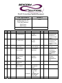


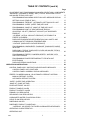
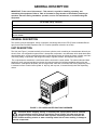
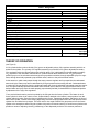

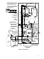


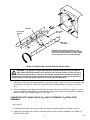


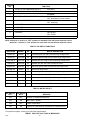


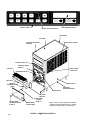
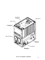
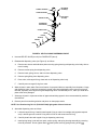


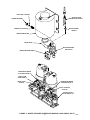


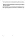
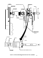
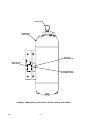
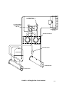


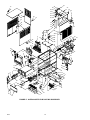
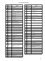
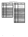
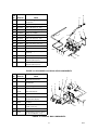

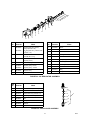
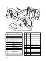


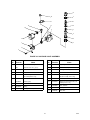
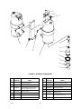
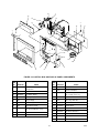
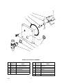
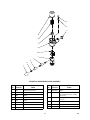

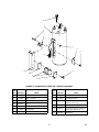
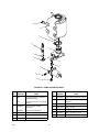
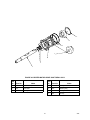


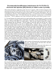


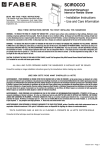
![Service Manual FCB Pinnacle 2 and 4 Flavor [ 005271 ]](http://vs1.manualzilla.com/store/data/006038828_1-2ffb9d6cd82d544c3f733521619945ce-150x150.png)