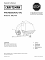
1
Operator's IVlanuai
CRnFTSMRH
°
ROFESSIONAL
VAC
DO NOT RETURN
TO STORE
For Missing Parts or Assembly
Questions Call 1-866-576-8388
IVlodei No. 486.24707
CAUTION:
,,
,,
,,
,,
,,
Before using this product, read
this manual and follow all Safety
Rules and Operating Instructions.
Sears, Roebuck
and Co., Hoffman
Safety
Assembly
Operation
Maintenance
Parts
Estates, IL 60179 U.S.A.
www.sears.com/craftsman
PRINTED IN U.S.A.
FORM NO. 40784 (08/13/08)
SAFETY RULES ..............................................................
3
ACCESSORIES ...............................................................
5
FULL SIZE HARDWARE CHART .................................... 6
CARTON CONTENTS .....................................................
8
ASSEMBLY ......................................................................
9
OPERATION ..................................................................
18
MAINTENANCE ............................................................
20
CRAFTSMAN
PROFESSIONAL
STORAGE AND OPTIONAL USE ................................. 21
TROUBLESHOOTING ...................................................
21
SLOPE GUIDE ..............................................................
27
REPAIR PARTS ILLUSTRATION ........................ 22,24,26
REPAIR PARTS LIST ................................................
23,25
PARTS ORDERING/SERVICE ................... BACK COVER
LiMiTED WARRANTY
Two Years on Powered Tractor Attachment
When operated and maintained according to all supplied instructions, if this Powered Attachment fails due to a defect in
material or workmanship within two years from the date or purchase, call 1-800-4-MY-HOME® to arrange for free repair.
This warranty applies for only one year from the date of purchase if this Powered Attachment is ever used for commercial
or rental purposes.
During the first year of purchase, there will be no charge for warranty service in your home. For your convenience, inhome warranty service will still be available after the first year of purchase, but a trip charge will apply. This charge will be
waived if you transport the tractor to an authorized Craftsman drop-off location. For the nearest authorized location, call
1-800-4-MY-HOME®.
This warranty
•
covers ONLY defects in material and workmanship.
Sears wi[[ NOT pay for:
Expendable items that become worn during normal use, including but not limited to blades, spark plugs, air cleaners,
belts, and oil filters.
Standard maintenance servicing, oil changes, or tune-ups.
Tire replacement or repair caused by punctures from outside objects, such as nails, thorns, stumps, or glass.
Tire or wheel replacement or repair resulting from normal wear, accident, or improper operation or maintenance.
Repairs necessary because of operator abuse, including but not limited to damage caused by improper transportation,
impacting objects that bend the frame or crankshaft, or over-speeding the engine.
Repairs necessary because of operator negligence, including but not limited to, electrical and mechanical damage
caused by improper storage, failure to use the proper grade and amount of engine oil, failure to keep the deck clear of
flammable debris, or failure to maintain the equipment according to the instructions contained in the operator's manual.
Engine (fuel system) cleaning or repairs caused by fuel determined to be contaminated or oxidized (stale). In general,
fuel should be used within 30 days of its purchase date.
Normal deterioration and wear of the exterior finishes, or product label replacement.
This warranty applies only while this product is within the United States.
This warranty gives you specific legal rights, and you may also have other rights which vary from state to state.
Sears, Roebuck and Co., Hoffman Estates, IL 60179
The model number and serial numbers will be found on
a decal attached to the Yard Vac.
MODEL NUMBER:
486.24707
SERIAL NUMBER:
You should record both the serial number and the date of
purchase and keep in a safe place for future reference.
2
DATE OF PURCHASE:
Cal11-866-576-8388formissingpartsorassemblyhelp
DO NOT RETURN TO STORE
Any power equipment can cause injury if operated improperly or if the user does not understand
equipment. Exercise caution at all times when using power equipment.
•
Read and follow all instructions in this manual before
attempting to assemble or operate this equipment. Failure
to comply with these instructions may result in personal
injury. Keep this manual in a safe place for future reference
and for ordering replacement parts.
Read this operating and service instruction manual
carefully. Be thoroughly familiar with the controls and proper
use of this power vacuum.
Read the vehicle owners manual and vehicle safe operation
rules before using this equipment.
Never allow children under 16 to operate this Vac System.
Children 16 years and older should only operate under
close parental supervision.
DO NOT allow anyone to operate this equipment without
proper instructions.
DO NOT allow passengers to ride on this equipment or the
towing vehicle.
Keep the area of operation clear of others, particularly
small children and pets.
Check fuel before starting engine. Do not fill fuel tank
indoors, while engine is running or while engine is hot. Wipe
off any spilled fuel before starting engine.
Engine and muffler get hot. Do not touch! To avoid fire
hazard, keep clean of debris and other accumulations.
Never store Vac System with fuel in tank. Allow engine to
coot before storing in any enclosure.
Do not change engine governor settings.
Do not operate engine if air cleaner or cover is removed
except for adjustment. Removal of these parts could create
a fire hazard.
Keep hands, feet, face, long hair and clothing out of inlet
and discharge area. There are ROTATING BLADES inside
these openings.
Before cleaning, repairing or inspecting, make certain
all moving parts come to a complete stop. Disconnect
spark plug wire and keep wire away from plug to prevent
accidental starting. Keep throttle control lever in stop
position.
If the Vac System should become blocked with debris
at any point, shut engine off and wait until the impeller
comes to a complete stop before attempting to remove
the obstruction. Disconnect spark plug wire to prevent
accidental starting.
how to operate the
If the cutting mechanism strikes a foreign object, or if your
Yard Vac should start to vibrate abnormally, stop the engine
immediately, disconnect spark plug wire and move the wire
away from the spark plug. Allow the machine to stop and
take the following steps.
a. Inspect for damage.
b. Repair or replace any damaged parts.
c. Check for loose parts and tighten to assure
continued safe operation.
Check all bolts for tightness at frequent intervals to help
insure safe operation.
Check top cover frequently for wear. Replace if worn or
damaged.
Never operate Yard Vac unless deck adapter, hose, hose
adapter (nozzle), discharge chute (elbow), and top cover
are properly attached in their place.
Do not remove top cover or attempt to empty contents of
cart while engine is running.
Never attempt to change hose adapter (nozzle) or to install
remote hose attachment when engine is running.
Keep all shields and guards (e.g. discharge chute (elbow)
and hose adapter (nozzle) in place and securely attached.
Always wear safety glasses or other suitable eye protection
when operating or maintaining this equipment.
Do not stand behind cart in exhaust discharge area while
engine is running.
Do not operate this equipment while intoxicated or while
taking drugs or medication that impairs the senses or
reactions.
When using this equipment, start the vehicle transmission
in first (low) gear and then gradually increase speed only as
conditions permit.
Operate this equipment at reduced speed on rough terrain,
along creeks and ditches and on slopes to prevent tipping
or loss of control. Do not drive too close to a creek or ditch.
Vehicle braking and stability are affected by the addition of
this equipment. Do not fill the Yard Vac to its full capacity
without checking the capability of the towing vehicle to
safely pull and stop with Yard Vac attached.
Before operating on any grade (hill) refer to the safety rules
in the vehicle owner's manual concerning safe operation on
slopes. Also refer to the SLOPE GUIDE on page 27 of this
owner's manual. Do not operate on slopes in excess of 10
degrees. STAY OFF STEEP SLOPES!
Follow the maintenance instructions outlined in this manual.
Look for this symbol to point out important safety precautions. It means -- Attention!!
safety is involved.
Become
alert!! Your
DANGER: This Vac System was built to be operated according to the rules for safe operation in this
manual. As with any type of power equipment, carelessness or error on the part of the operator can
result in serious injury'. This unit is capable of amputating fingers and hands and throwing objects. Failure
to observe the safety instructions could result in serious injury or death.
Call 1-866-576-8388 for missing parts or assembly help
DO NOT RETURN TO STORE
3
TO AVOID SERIOUS iNJURY
=
o
Read Owner's Manual and all safety labels on machine before starting and using machine.
Do Not remove top cover or attempt to empty contents of cart while engine is running.
Do Not stand behind cart in exhaust discharge area while engine is running.
Keep hands, feet, face, long hair and clothing out of chipper inlet, vac inlet, and discharge
area. There are ROTATING BLADES inside these openings.
Wear approved safety glasses and gloves. Avoid loose fitting clothes.
Keep the area of operation clear of all persons, particularly small children and pets.
Keep all shields and guards (e.g. upper chipper chute extension, discharge chute, nozzle
assembly) in place and securely attached.
Check discharge boot frequently for wear. Replace if worn or damaged.
If unit becomes clogged or jammed, shut off engine right away. Do Not attempt to clear
clog or jam with engine running.
Muffler and engine get hot and can cause burns. Do Not Touch. To avoid a fire hazard,
keep leaves, grass and other combustible debris off hot muffler and engine.
Do Not attempt to remove or attach vac nozzle or optional Hose Kit with engine running.
Do Not operate unit unless nozzle or optional Hose Kit is secured in place.
Do Not fill gas tank while engine is running. Allow engine to coot at least 2 minutes before
refueling.
WARNING
|
I_
I
|
OPENINGS.
NOT REMOVE
OR INSIDE.
ATTACH KEEP
HOSE,HANDS
HOSE ADAPTER,
ELBOW
HAZARDOUS DO
ROTATING
BLADES
AWAY FROM
ALL OR
OPTIONAL HOSE KITWHEN ENGINE IS RUNNING!
WA
I
This unit is equipped with an internal combustion engine and should not be used on or near unimproved forest-covered, or
grass-covered land unless the engine's exhaust system is equipped with a spark arrester meeting applicable local or state
laws (if any). If a spark attester is used, it should be maintained in effective working order by the operator.
In the State of California the above is required by law (Section 4442 of the California Public Resources Code). Other
states may have similar laws. Federal laws apply on federal lands. A spark attester muffler is available at your nearest
engine authorized service center.
4
Call 1-866-576-8388
for missing parts or assembly help
DO NOT RETURN TO STORE
These accessories were available when the unit was purchased. They are also available at most Sears retail outlets and
service centers. Most Sears stores can order repair parts for you when you provide the model numbers of your tractor and
Yard Vac System.
\
\
/
\
\
/t
\
The Hand Wand Attachment, Model 486.24509
provides a 12' x 5" diameter hose to clean
around shrubs, patios, window wells and other
areas not accessible to the tractor.
Call 1-866-576-8388 for missing parts or assembly help
DO NOT RETURN TO STORE
5
A
jE
jB
............
_
jH
Q
/
\
NOT SHOWN
FULL SIZE
l\
\\
\\\\
(©
6
REF.
QTY.
A
1
B
DESCRiPTiON
RER
QTY.
DESCRiPTiON
Hex Bolt, 5/16-18 x 4"
M
9
Nylock Nut, 3/8-16
5
Hex Bolt, 3/8-16 x 3"
N
1
Nylock Nut, 1/2-13
C
1
Hex Bolt, 1/2-13 x 1-1/2"
O
4
Nylon Washer
D
4
Hex Bolt, 1/4-20 x 1-1/4"
P
6
Washer, 1/4"
E
4
Hex Bolt, 3/8-16 x 1"
Q
4
Washer, 5/8"
F
10
Hex Bolt, 1/4-20 x 3/4"
R
1
Washer, 7/16"
G
4
Bolt, 5/16-18 x 3/4" Self-Tapping
S
2
Cotter Pin
H
8
Truss Head Bolt, 5/16-18 x 3/4"
T
1
Hair Cotter Pin
Lock Nut, 1/4-20
U
3
Wing Nut, 5/16-18
I
6
J
11
Flanged Nut, 1/4-20
V
1
Spring
K
4
Nylock Nut, 1/4-20
W
1
Hitch Pin
L
9
Nylock Nut, 5/16-18
X
2
Axle Clip
Y
2
Plug
Call 1-866-576-8388
for missing parts or assembly help
DO NOT RETURN TO STORE
jC
NOT SHOWN FULL SIZE
\
J
REF.
QTY.
DESCRiPTiON
A
2
Hex Bolt, 1/4-20 x 1-1/4"
REF.
QTY.
H
12
DESCRiPTiON
Washer, 5/16" Standard
B
2
Hex Bolt, 5/16-18 x 1-1/4"
I
5
Nylon Washer
C
4
Hex Bolt, 1/4-20 x 3/4"
J
2
Tarp Strap
D
2
Carriage Bolt, 5/16-18 x 3/4"
K
1
Angle Bracket
E
6
Washer, 1/4" Standard
L
2
"S" Hook
F
3
Nylock Nut, 5/16-18
M
1
Mounting Strap
G
5
Nylock Nut, 1/4-20
N
1
Mounting Bracket
Call 1-866-576-8388 for missing parts or assembly help
DO NOT RETURN TO STORE
7
11
J
13
18
,15
17
26
22
28
24
27
/
23
/
REF.
QTY.
1
1
Cart Tray
15
]
2
1
Cover
16
2
REF.
QTY.
DESCRIPTION
Lower Support Rod
]
Tarp Strap (25")
Latch Stand Bracket
3
1
Engine
17
4
1
Hose Adapter
18
]
5
1
Rope
19
]
Hose Hanger Rod
Latch Stand Plate
Front Tongue
2O
]
Top Support Angle
Rear Tongue
21
]
Deck Adapter
2
Cart Bed Brace
6
7
1
1
8
1
Elbow w/Deflector
22
9
2
Hose Clamp
23
]
Axle
10
2
Wheel
24
]
Front Support Tube
Wheel Support
25
]
Latch Lock Lever
]
Hitch Bracket
11
8
DESCRIPTION
1
12
1
Hose
26
13
1
Hitch Plate
27
]
Front Support Rod
14
2
Brace
28
]
Adapter Bracket
Call 1-866-576-8388
for missing parts or assembly help
DO NOT RETURN TO STORE
This unit is shipped WITHOUT GASOLINE or OiL. After
assembly, see separate engine manual for proper fuel
and engine oil recommendations.
TOOLS
REQUIRED
FOR ASSEMBLY
(1) Screwdriver
(!) Pliers
(2) 7/1 6" Wrenches
(2) 1/2" Wrench
(2) 9/1 6" Wrenches
(2) 3/4" Wrenches (only if figure 12 on page 12 is used)
REMOVAL
•
Attach the hitch bracket to the front tongue using two
3/8" x 1" bolts and 3/8" nylock nuts. See figure 2.
Assemble the front tongue on top of the rear tongue
using three 3/8" x 3" hex bolts and 3/8" nylock nuts.
See figure 2.
Install the hitch pin and the hair cotter pin in the hitch
bracket and front tongue. See figure 2.
3/8" × 3"
HEX BOLT
HITCH PiN
OF PARTS FROM CARTONS
318"× 1"
Remove the hardware packs and all loose parts from
the cartons.
Lay out and identify parts shown in carton contents.
Lay out and identify parts in the hardware packs.
Keep contents of each hardware package separate.
HEX BOLT
X
X
CART ASSEMBLY
3/8" NYLOCK NUT _
Assemble latch lock lever to rear tongue using 5/16"
x 4" hex bolt and 5/16" nylock nut. Tighten nut until
snug against side of rear tongue. See figure 1A.
Attach the spring to the hole in the latch lock lever
and the hole in the tongue. See figure 1B.
LATCH
LOCK
LEVER
5/16" NYLOCK NUT
/
/"
@@
i
HAiR
.,......._%
COTTER PiN
FIGURE 2
Assemble the rear tongue to the wheel support by
sliding the axle through the holes in the tongue and
wheel support as shown in figure 3.
WELDED PLATE
_
HOLE FOR AXLE
5/16" x 4"
HEX BOLT
FIGURE 1
Call 1-866-576-8388 for missing parts or assembly help
DO NOT RETURN TO STORE
FIGURE 3
9
Assemble
anaxleclip,a wheelanda 5/8"washeronto
eachendoftheaxle.Assemble
a second5/8"washer
ontoeachendoftheaxleifspaceallows.Secureboth
wheelsinplaceusingtwocotterpins.Seefigure4.
WHEEL
FLAT
WASHER
\
Place the cart bed braces and the cart tray onto
the wheel support. Secure latch stand bracket
underneath the tongue's latch lock lever. See figure 6.
Assemble the cart tray and cart bed braces to the
wheel support using eight 5/16" truss head bolts and
5/16" nylock nuts. Tighten nuts after all bolts are in
place. See figure 6.
AXLE
5/16"TRUSS
HEAD BOLT
FIGURE 4
/
CART
BED
BRACE
Assemble the latch stand plate and latch stand
bracket (with alignment tab toward rear of cart) to the
cart tray using four 1/4" x 3/4" hex bolts, 1/4" washers
and 1/4" nylock nuts. Tighten nuts after all bolts are in
place. See figure 5.
I
FIGURE 6
114"x 314"
HEX BOLTS
I_"NYLOCK
NUT
FIGURE 5
10
Cal11-866-576-8388formissingpartsorassemblyhelp
DO NOT RETURN TO STORE
Attach the engine mounting plate to the tongues
using two 3/8" x 3" hex bolts in the back holes, two
3/8" x 1" hex bolts in the front holes and four 3/8"
nylock nuts. See figure 7.
Place the hose hanger rod down into the hose hanger
bracket on the impeller housing assembly. See figure
9.
\
\\\
HINT:
\
\
For easier assembly, support the rear tongue with
a block of wood.
HOSE HANGER
ROD
\
\
\
\
\
3/8" x 1"
HEX BOLT
3/8" × 3"
HEX BOLT
6
i i
3/8" NYLOCK NUT
FIGURE 9
FIGURE 7
*
Attach the plastic elbow to the top of the engine
housing using four 5/16" x 3/4" hex bolts (self
tapping) and nylon washers. See figure 8.
HINT: Push in on hex bolts as you tighten to form threads.
*
Connect the hose adapter to the engine housing by
fastening three wing nuts to the pre-assembled bolts
in the engine housing. See figure 8.
Place a hose clamp onto the end of the hose. Push
the hose onto the hose adapter (nozzle). Tighten the
hose clamp onto the hose and hose adapter. Do not
collapse the hose adapter when tightening the clamp.
See figure 10.
The remaining hose clamp will be used later to fasten
the hose to the deck adapter.
HOSE ADAPTER
(NOZZLE)
HOSE CLAMP
NYLON WASHER
---_
b5/16" X 3/4"
HEX BOLT
(SELFTAP)
FIGURE 8
Cal11-866-576-8388formissingpartsorassemblyhelp
DO NOT RETURN TO STORE
FIGURE 10
11
Loop the 25" tarp strap under the hose. Fasten the
hooks to the hose hanger rod. See figure 11.
CART COVER ASSEMBLY
•
HOSE HANGER ROD
\
Slide the front support tube through the double loops
at the front of the cart cover. See figure 13.
DOUBLE LOOPS
25" TARP
STRAP
FRONT
SUPPORT
TUBE
FIGURE 11
CART COVER
FIGURE 13
Assemble the hitch plate to the tractor hitch if:
Your tractor has a square (straight) hitch frame, to
help prevent binding.
Your tractor has a lightweight hitch frame that
needs reinforcement for towing.
Use a 1/2" x 1-1/2" hex bolt, a 7/16" flat washer and a
1/2" nylock nut. See figure 12.
Slide the front support rod (straight ends) through the
front sleeve located in the top of the cart cover. Slide
a lower support rod (bent ends) through the rear
sleeve located behind the front sleeve. The bend in
the rod must face in the direction shown in figure 14.
1/2" x 1-1/2"
HEX BOLT......_
ATTACH
MOW=N=VAC
HERE
TRACTOR HITCH
FRAME (S_ IUARE)
HITCH
PLATE
7/16" FLAT WASHERJ_
J
1/2" NYLOCK NUT
_ _ _ J _/_ _
,/
TRACTOR HITCH
FRAME (TAPERED) _--.
_J
FIGURE 12
FIGURE 14
12
Call 1-868-578-8388
for missing parts or assembly help
DO NOT RETURN TO STORE
Slide the second lower support rod (bent ends)
through the sleeve along the bottom of the cart cover.
Slide an end of the rope onto the end of the rod as it
approaches each gap in the sleeve. The bend in the
rod must face in the direction shown in figure 15.
Place the top support angle inside the cart cover.
Push the long plastic strip stitched to the bottom of
the cover onto three welded bolts in the top support
angle. Attach the two short plastic strips to the top
support angle using two plastic plugs as shown in
figure 17.
BOTTOM OF
CART COVER
PLASTIC
PLUG
ROPE
3END
LOWER
SUPPORT
PLASTIC
STRIPS,
"_
BOTTOM SLEEVE
WELDED BOLT
TOP SUPPORT ANGLE
FIGURE 15
FIGURE 17
Locate the plastic strips that are stitched to the
bottom of the cart cover. Cut seven slits in the cover
fabric that align with the holes in the plastic strips.
See figure 16.
CUT SLITS (7)
PLASTIC STRIPS
FIGURE 16
Call 1-888-578-8388 for missing parts or assembly help
DO NOT RETURN TO STORE
13
Securefrontsupporttubetotopsupportangle
usingtwo1/4"x 1-1/4"hexboltsand1/4"locknuts.
TIGHTEN. Do not over tighten and collapse support
tube. See figure 18.
NOTE: Cart bag not shown for clarity.
/
/
•
•
Assemble a 1/4" x 3/4" bolt and 1/4" lock nut to each
end of the second lower support rod. TIGHTEN, then
back nut off 1/2 turn. See figure 20.
Attach the lower support rod to the outside of the top
support angle using two 1/4" flanged nuts. TIGHTEN.
See figure 20.
NOTE: Cart bag not shown for clarity.
FRONT SUPPORTTUBE
TOP SUPPORT ANGLE
.-
I
.-'_"''"
LOWER SUPPORT
ROD (BENT)
114" FLANGED
\
NUT
\
1/4" x 1-1/4" HEX BOLT
114" LOCK
NUT
FIGURE 18
Place the front support rod on the outside and the
lower support rod on the inside of the top angle
support. Attach using two 1/4" x 3/4" hex bolts and
1/4" lock nuts. TIGHTEN nut only until flush with end
of bolt. The rods must pivot freely. See figure 19.
NOTE: Cart bag not shown for clarity.
114" x 314"
HEX BOLT
FIGURE 20
Attach the braces to the front support tube using
two 1/4" x 1-1/4" hex bolts and 1/4" flanged nuts.
TIGHTEN. Do not over tighten and collapse support
tube. See figure 21.
NOTE: Cart bag not shown for clarity.
FRONT SUPPORT ROD
(STRAIGHT)
LOWER SUPPORT ROD
(BENT)
LOCK NUT
114" x 314" HEX BOLT
FIGURE
14
19
114" x 1-114"
HEX BOLT
FIGURE 21
Call 1-866-576-8388
for missing parts or assembly help
DO NOT RETURN TO STORE
•
Place the assembled cart cover on top of the cart,
fitting the welded bolts in the top support angle down
into the holes in the cart. Assemble five 1/4" flanged
nuts onto the welded bolts. DO NOT TIGHTEN YET.
See figure 22.
Attach the braces to the top support angle and cart
using two 1/4" x 3/4" hex bolts, 1/4" washers and 1/4"
flanged nuts. TIGHTEN. See figure 22.
TIGHTEN the nuts on the welded bolts.
With the rope hanging down loosely', check if the
cover fits down freely around the rear of the cart tray.
If the cover needs to extend farther to the rear, loosen
bolts (a) in figure 23 to slide the support rod rearward.
If the rear of the cover does not rest down freely
around the rear of the cart tray, loosen bolts (b) in
figure 23 and tilt the front support tube rearward while
sliding the bottom of the braces rearward.
114" x 314"
HEX BOLT
1/4"
WASHER
BOLT
B
BOLT
FIGURE
FIGURE 22
23
Allow the rope to hang loosely behind the rear of the
cart. Use the lanyard to tighten the rope until it firmly
secures the cart cover to the cart. See figure 24.
Ensure lanyard is locked to keep rope in place. See
figure 24.
FIGURE 24
Call 1-866-576-8388 for missing parts or assembly help
DO NOT RETURN TO STORE
15
BEFORE PROCEEDING,
look in the fold-out sheets included with this manual
to find templates for Sears mower decks, if written instructions are printed on the
template, follow those instructions instead of the instructions in this manual.
ASSEMBLING
THE #62468
TOTHE
MOWER DECK
DECK ADAPTER
Position the adapter over the deck opening, and check
for fit of cutout as shown in figure 26. Trim cutout, if
necessary, to allow tilting of adapter, keeping the fit as
close as possible for best vacuum suction.
NOTE: Not all of the parts in the deck adapter hardware
package will be needed for your particular fit up.
•
NOTE:
Make sure adapter clears gauge
wheels on mower deck
Remove the mower discharge deflector from your
mower deck. Save the deflector and hardware for
remounting deflector.
DECK ADAPTER
/
MOWER DECK
CAUTION: Mower deflector must be
replaced when Vac System deck adapter
is removed. Do Not operate mower
unless adapter or deflector is in place and
properly mounted.
Curl on deck may be located outside of adapter
or inside depending on deck opening design
Identify and cut out the template for your brand and
size mower deck. If there is no template included for
your deck size, you can make your own template by
marking around a piece of cardboard held against the
edge of the deck's discharge opening.
Tape the template to the face of the adapter, about
1/2" from front and 1/4" down from top for deeper
decks. For shallow decks, position template low
enough that adapter will not extend below bottom
of deck. Mark outline of template on face of adapter
using white crayon, nail or scriber. Drill a starting
hole inside the outline, then use a saber saw or key
hole saw to cut out the opening. See figure 25.
FIGURE 26
Holding the adapter bracket and the deck adapter
together, position the deck adapter on the mower deck.
Keeping the edge of deck adapter as close as possible
to the offset in the adapter bracket, see if the slot in
the adapter bracket can be aligned with one or two of
the deflector holes in your mower deck's discharge
opening. If the bracket can not be located correctly
using existing holes, it will be necessary to drill one or
two 5/16" diameter holes in the deck. See figure 27.
Use existing holes or drill 5/16"
diameter hole or holes.
ADAPTER BRACKET
1/4" DOWN
IMPORTANT:
Keep cut-off as close to
the top edge as possible.
\\\
\
\\\\\\
DECK ADAPTER
MOWER DECK
1/2" FROM FRONT
FIGURE 25
Keep edge of adapter as close
as possible to offset in bracket
FIGURE 27
16
Call 1-866-576-8388
for missing parts or assembly help
DO NOT RETURN TO STORE
•
Assemble the adapter bracket to the deck using two
5/16" x 1-1/4" hex bolts, 5/16" flat washers and 5/16"
nylock nuts. See figure 28.
NOTE: It may be necessary to use extra 5/16" flat
washers to shim under the bracket next to the deck
surface. Ten extra washers have been furnished as
shims. See figure 28.
With deck adapter positioned correctly over the
discharge opening, use the adapter bracket as a
template and drill three 9/32" diameter holes in the
top of the deck adapter. See figure 29.
Bolt deck adapter to bracket using three 1/4" x 3/4"
bolts, nylon washers, 1/4" flat washers and 1/4"
nylock nuts. Nylon washers should be against the
inside of the deck adapter. See figure 29.
(2) 5/16" NYLOCK
i
@_
NUTS
1_---- (2) 5116"FLAT
WASHERS
DECK ADAPTER
_
(3) 1/4" NYLOCK
NUTS
BRACKET
ADAPTER BRACKET
5/16" x 1-1/4" _"_
HEX BOLT
5116" flat washers
used as needed for
shims to adjust for
variations in decks.
FIGURE 28
WASHERS
(3) 1/4" STEEL WASHERS
(3) 1/4" x 3/4" HEX BOLTS
FIGURE
29
Assemble end of hose and a hose clamp over the
round opening of deck adapter and tighten clamp.
GO DIRECTLY TO THE OPERATION
INSTRUCTIONS ON PAGE 18.
Call 1-866-576-8388 for missing parts or assembly help
DO NOT RETURN TO STORE
17
KNOW YOUR VAC SYSTEM
Read this owner's manual and safety rules before operating your Vac System.
Compare the illustration below with your Vac System to familiarize yourself with the various controls and their locations.
CHOKE
CONTROL
THROTTLE
CONTROL
LATCH LOCK LEVER
LATCH LOCK LEVER Locks the cart bed down to the
tongue. Releases to allow cart to be tipped back for
dumping.
BOOT Connects the plastic elbow to the fabric top,
directing discharged material into the cart.
CHOKE CONTROL
THROTTLE CONTROL
Adjust to allow cold starting.
Controls speed of engine.
CAUTION:
Alcohol blended fuels (called gasohol or using
ethanol or methanol) can attract moisture which leads to
separation and formation of acids during storage. Acidic gas can
damage the fuel system of an engine while in storage.
To avoid engine problems, the fuel system should be emptied
before storage for 30 days or longer. Drain the gas tank, start
the engine and let it run until the fuel lines and carburetor are
empty. Use fresh fuel next season.
BEFORE
•
STARTING
Your Vac System engine is shipped without oil or
gasoline. Service the engine with oil and gas as
instructed in the separate engine manual.
Inspect the Vac System to make sure all covers (rear
door, vinyl boot, elbow, hose adapter, hose and deck
adapter are properly attached.
Check tires for proper inflation (12 - 14 Ibs).
See STORAGE Instructions for additional information.
Never use engine or carburetor cleaner products in the fuel tank
or permanent damage may occur.
WARNING: Never fill fuel tank indoors, or
with the engine running, or while the engine
is hot. Do not smoke while filling tank.
HOW TO STOP YOUR VAC SYSTEM
To stop engine, move the throttle control lever to the
OFF position.
Disconnect spark plug wire from plug to prevent
accidental starting while equipment is unattended or
is being worked on.
CAUTION:
are hot!
18
The muffler and adjacent areas
Call 1-866-576-8388
for missing parts or assembly help
DO NOT RETURN TO STORE
HOW TO STARTYOUR
VAC SYSTEM
WARNING: Never start or run the engine
without all covers being properly attached to
the blower housing and cart.
•
Check oil and gas in Vac engine.
Attach spark plug wire to spark plug.
Move choke lever on engine to CHOKE position.
(A warm engine may not require choking.)
Move throttle control lever on engine to FAST
position.
Grasp starter handle and pull rope out slowly until
engine reaches start of compression cycle (rope will
pull slightly harder at this point). Let the rope rewind
slowly.
Pull rope with a rapid, continuous, full arm stroke.
Keep a firm grip on starter handle. Let rope rewind
slowly. Do not let starter handle snap back against
starter.
Repeat instructions in two preceding paragraphs until
engine fires. When engine starts, move choke control
gradually to RUN position.
TO EMPTY THE CART
Shut off the tractor engine and set the brake.
Shut off the Vac engine.
Loosen draw string and pull boot back from the elbow.
Use rope to secure cover in upright position. Refer to
illustration below.
Release latch lock lever on tongue and tip cart back.
Using a rake or suitable tool, pull grass clippings and/
or leaves out of the cart.
Call 1-866-576-8388 for missing parts or assembly help
DO NOT RETURN TO STORE
HOW TO USE YOUR VAC SYSTEM
CAUTION:
Vehicle braking and stability
may be affected with the addition of an
accessory or an attachment. Be aware of
changing conditions on slopes.
Inspect the Vac to make sure the cover, rear door,
boot, elbow, hose adapter (nozzle), hose and deck
adapter are properly attached.
Check tires for proper inflation (12 - 14 Ibs).
Check for oil and gas in Vac engine.
Begin operation at low speed, adjusting forward
speed to match grass height and/or moisture
condition to prevent clogging.
Do not attempt to vacuum up any material other
than vegetation found in a normal yard, such as light
branches, leaves, twigs, etc.
WARNING: Should your Vac System
become clogged, shut off tractor and Vac
engines. Before attempting to unclog,
remove wire from spark plug to prevent
accidental starting.
After the cart is emptied, tip it forward and secure it to
the tongue with the latch lock lever. Fold down cover
and secure in place with the rope.
CAUTION: To avoid possible injury, be sure
that no one is near the cart before releasing
the latch lock lever.
19
CUSTOMER
•
RESPONSiBiLiTiES
Read and follow the maintenance schedule and the maintenance procedures listed in this section.
MA,=TE=A=OE
SCHEDULE
Fill in dates as you
complete regular service.
Check for loose fasteners
Check cover
Check tire pressure
ch_
_ng!n_ oi! !ev_t
Lubricate
Clean
!_,_'__P_./'I",
ee;Ze_Y
/,/_/,_/_°/_
'>"
X
X
X
_
X
X
X
Service Dates
Maintain engine per instructions below and in engine manual.
BEFORE
EACH USE
WARNING: Always stop engine and
disconnect spark plug wire before
cleaning, lubricating or before performing
any repairs or maintenance.
CHECK FOR LOOSE FASTENERS
Make a thorough visual check of the Vac System
for any bolts and nuts which may have loosened.
Retighten any loose bolts and nuts.
CHECK COVER
Check the cover, especially the front boot and the
rear flap for wear. Replace cover if worn or damaged.
CHECK TIRE PRESSURE
Check tire pressure regularly. Recommended tire
pressure is 12-14 Lbs.
CHECK ENGINE OIL LEVEL
Check oil level before each use. Maintain engine oil
as instructed in the separate engine manual.
LUBRICATION
At the beginning of each season, lubricate the latch,
latch pivot bolt, and the axle where the hitch tongue
pivots, with a light machine oil.
At least once a season, grease or oil the wheel
bearings. Use automotive wheel bearing type grease
or 20 weight oil.
ENGINE
MAINTENANCE
Only use high quality detergent oil rated with API service
classification SF or SG. Select the oil's SAE viscosity
grade according to your expected operating temperature.
SAE 30 grade oil is recommended for warm weather use.
For cold weather use refer to the engine manufacturer's
Operating and Maintenance Manual.
Check oil level before each use. Maintain engine oil
as instructed in the separate engine manual.
Service air cleaner every 25 hours under normal
conditions. Clean every few hours under extremely
dusty conditions. Poor engine performance and
flooding usually indicates that the air cleaner should
be serviced. To service the air cleaner, refer to the
separate engine manual.
The spark plug should be cleaned and the gap reset
once a season. Spark plug replacement at the start
of each season is recommended. Check the engine
manual for correct plug type and gap specifications.
CLEANING
Make sure the cart and top are cleaned after each
use. Grass clippings and leaves left in the cart will
mildew and cause damage if not cleaned out.
Clean the engine regularly with a cloth or brush.
Keep the cooling fins on the engine housing clean
to permit proper air circulation which is essential to
engine performance and life. Be sure to remove all
dirt and debris from muffler area.
20
Call 1-866-576-8388
for missing parts or assembly help
DO NOT RETURN TO STORE
•
•
Clean the engine and the entire unit thoroughly.
Refer to engine manual for correct engine storage
instructions.
TO USE THE CART WITHOUT THE VAC SYSTEM
Remove bolts holding frame to cart and store bag
and frame in a safe place.
If storing in an unventilated or metal storage shed,
coat metal parts with light oil or silicone to prevent
rust.
Store unit in a clean, dry area.
It is important to prevent gum deposits from forming in
essential fuel system parts such as the carburetor, fuel
filter, fuel hose or tank during storage. Also, alcohol
blended fuels (called gasohol or using ethanol or
methanol) can attract moisture which leads to separation
and formation of acids during storage. Acidic gas can
damage the fuel system of an engine while in storage.
CAUTION:
are hot!
The muffler and adjacent areas
Keep removed bolts, washers and nuts in a safe
place with bag.
Remove and store the four bolts and nuts which
fasten the engine base to the tongue.
Slide the engine off the tongue and store in a safe
storage area.
To avoid engine problems, the fuel system should be
emptied before storage of 30 days or longer. Follow the
instructions in the engine's Operating &
Maintenance Manual.
PROBLEM
POSSIBLE
Engine fails to start
1. Spark plug wire disconnected.
1. Connect wire to spark plug.
2. Safety switch not contacted.
2. Correctly install hose adapter nozzle.
3. Fuel tank empty, or stale fuel.
3. Fill tank with clean, fresh fuel.
4. Fuel shut-off valve closed (if so
equipped).
4. Open fuel shut-off valve.
5. Faulty spark plug.
5. Clean, adjust gap or replace.
Loss of power;
1. Spark plug wire loose
1. Connect and tighten spark plug wire.
operation erratic.
2. Unit running on CHOKE.
2. Move choke lever to OFF position.
3. Blocked fuel line or stale fuel.
3. Clean fuel line; fill tank with clean fresh gasoline.
4. Disconnect fuel line at carburetor to drain fuel tank. Refill
with fresh fuel.
CAUSE(S)
4. Water or dirt in fuel system.
5. Carburetor out of adjustment.
Engine overheats
Too much vibration
Unit does not
discharge
CORRECTIVE ACTION
6. Dirty air cleaner.
5. Adjust carburetor.*
6. Service air cleaner.*
1. Carburetor not adjusted properly.
1. Adjust carburetor.*
2. Engine oil level low.
2. Fill crankcase with proper oil.
1. Loose parts or damaged impeller.
1. Stop engine immediately and disconnect spark plug
wire. Tighten all bolts and nuts. Make all necessary repairs.
If vibration continues, have unit serviced by an authorized
service dealer.
Discharge chute (elbow) clogged.
1. Stop engine immediately and disconnect spark plug
wire. Clean inside of housing and discharge chute (elbow).
.
2. Foreign object lodged in impeller.
2. Stop engine immediately and disconnect spark plug
wire. Remove lodged object.
3. Vac Cart is full.
3. Empty cart.
*Refer to the engine manual packed with your unit.
NOTE: For repairs beyond the minor adjustments listed above, please contact your nearest authorized service dealer.
Call 1-866-576-8388 for missing parts or assembly help
DO NOT RETURN TO STORE
21
REPAIR PARTS LiST FOR 486.24707 PROFESSIONAL
VAC
5
/
jl
15
/
•
9
27
\
4
i
I
7
\
16
\
18
,
I
r
I
I
I
I
/
22
\
11
i
2O
18
\
/
I
I
" /
©
6
26
/
14
23
/
24
22
Call 1-866-576-8388
for missing parts or assembly help
DO NOT RETURN TO STORE
REPAIR PARTS LIST FOR 486.24707 PROFESSIONAL
REF.
NO.
PART NO.
QTY.
1
48791
1
2
43088
DESCRiPTiON
REF.
NO.
PART NO.
QTY.
DESCRiPTiON
Cart Tray
15
25875
2
Cart Bed Brace
4
Washer, 1/4" Std.
16
25910
2
Axle Clip
VAC
3
43012
4
Hex Bolt, 1/4-20 x 3/4"
17
47189
4
Nylock Nut, 1/4-20
4
24386
1
Latch Stand Plate
18
47810
9
Nylock Nut, 5/16-18
5
43814
8
Truss Head Bolt, 5/16-18
19
R19212016
4
Washer, 5/8"
6
26008
1
Axle
20
43010
2
Cotter Pin
7
48497
2
Wheel
21
23353
1
Hitch Pin
8
65442Y
1
Rear Tongue
22
43001
2
Hex Bolt, 3/8-16 x 1"
Nylock Nut, 3/8-16
9
24527Y
1
Wheel Support
23
HA21362
5
10
24497Y
1
Latch Stand Bracket
24
43343
1
Hair Cotter Pin, 3/32"
11
25742Y
1
Front Tongue
25
43574
3
Hex Bolt, 3/8-16 x 3"
12
23475
1
Hitch Bracket
26
47407
1
Hex Bolt, 5/16-18 x 4"
13
25010
1
Latch Lock Lever
27
65518
1
Rope, 36"
14
HA20186
1
Spring
Call 1-866-576-8388 for missing parts or assembly help
DO NOT RETURN TO STORE
23
REPAIR PARTS FOR MODEL 486.24707 PROFESSIONAL
VAC
37
42
3
\27
43
10
/
4
42
ADAPTER
#62468
17
20
21
12
8
40
J
_3334
41
27
28 .......
14
30 ...... _ "_"
8
/
13
/
29+_+_
12
TO
TRACTOR
32
24
Call 1-866-576-8388
for missing parts or assembly help
DO NOT RETURN TO STORE
REPAIR PARTS FOR MODEL 486.24707 PROFESSIONAL
REF.
NO.
PART NO.
QTY. DESCRiPTiON
1
66075
1
2
25874
1
3
25876
4
VAC
REF.
NO.
PART NO.
QTY. DESCRiPTiON
Top Support Angle Assembly
24
43574
2
Hex Bolt, 3/8-16 x 3"
Front Support Tube
25
43088
8
Washer, 1/4" Std.
2
Brace
26
23540
1
Hitch Plate
49873
2
Lower Support Rod
27
1543-69
9
Nylon Washer
5
43840
2
Hex Bolt, 5/16-18 x 1-1/4"
28
43351
1
Hex Bolt, 1/2-13 x 1-1/4"
6
40343
1
Cart Cover
29
712-3028
1
Nylock Nut, 1/2-13
7
40996
1
Engine (49 State)
30
43352
1
Flat Washer, 7/16"
40999
1
Engine (California)
31
43081
12
Washer, 5/16" Std.
8
47810
7
Nylock Nut, 5/16-18
32
43830
1
Deck Adapter
9
25873
1
Engine Mounting Base
33
23560
1
Deck Adapter Bracket
10
65428
1
Impeller Housing Assembly
34
43080
2
Carriage Bolt, 5/16"x 3/4"
(See page 26)
35
23825
1
Mounting Strap
Hose Adapter
36
23826
1
Angle Bracket
Hex Bolt, 1/4-20 x 3/4"
49872
43085
1
Front Support Rod
11
43791
1
12
43012
14
13
47189
5
Nylock Nut, 1/4-20
37
38
4
Hex Bolt, 5/16-18 x 1-1/2"
14
43792
1
Hose
39
HA21362
4
Nylock Nut, 3/8-16
15
49974
1
Hose Hanger Rod
4O
62468
1
Deck Adapter Kit
16
46420
1
Deflector w/Elbow
41
23827
1
Mounting Bracket
17
712-0421
3
Wing Nut
42
1509-90
6
Hex Bolt, 1/4-20 x 1-1/4"
43
47630
4
Hex Bolt, 5/16-18 x 3/4"
18
43013
6
Lock Nut, 1/4-20
19
48402
2
Plug, Plastic
20
44850
2
Tarp Strap
44
43001
2
21
44849
2
"S" Hook
45
47598
22
43793
2
Hose Clamp
11
1
23
43790
1
Tarp Strap, 25"
Ca111-866-576-8388 brmissingpartsorassemblyhelp
DO NOT RETURN TO STORE
(Thread Forming)
40784
Hex Bolt, 3/8-16 x 1"
Nut, Hex Flange 1/4-20
Owners Manual
25
REPAIR PARTS LIST FOR 486.24707 PROFESSIONAL
VAC
REF.
NO.
PART
NO.
QTY.
DESCRiPTiON
REF.
NO.
PART
NO.
QTY.
1
629-0241A
1
Harness, Wire
13
725-3166
1
Snap Mount Switch
2
24634
1
Housing Assembly, Inner
14
726-0272
1
Clamp
3
24633
1
Housing Assembly, Outer
15
731-1613
1
Switch Cover
4
43182
12
Hex Bolt, 5/16-18 x 3/4"
16
24958
1
Hose Hanger Bracket
5
40320
4
Hex Bolt, 5/16-24 x 1-1/4"
17
48848
3
Nylock Jam Nut, 5/16-18
6
710-1268
2
Screw, Self Tap #10-16 x 3/8"
18
43081
4
Washer, 5/16" Std.
7
43063
3
Hex Bolt, 5/16-18 x 1"
19
736-0247
1
Washer
8
712-0421
3
Wingnut
2O
65428
1
Impeller Assembly
9
47810
12
Nylock Nut, 5/16-18
21
44377
1
Hex Bolt, 3/8-24 x 1"
Lock Washer, 5/16"
22
43003
1
Lockwasher, 3/8"
49869
1
Wire Mag. Ground
23477
1
Key, 1/4 Sq. 2" Long
26
10
43086
11
23727
4
Spacer
23
12
725-1700
1
Switch Cover
24
4
DESCRiPTiON
Call 1-866-576-8388
for missing parts or assembly help
DO NOT RETURN TO STORE
SUGGESTED GUIDE FOR SIGHTING
OF TRACTOR WITH ATTACHMENT
SLOPES FOR SAFE OPERATION
LINE
SLO
ONLY RIDE UP AND DOWN
NOT ACROSS HILL
10 DEGREES
&
HILL,
MAX.
WARNING: To avoid serious injury, operate your tractor up and
down the face of slopes, never across the face. Do not operate
on slopes greater than 10 degrees. Make turns gradually to
prevent tipping or loss of control. Exercise extreme caution
when changing direction on slopes. Braking may be affected by
tractor attachment. Reduce speed on slopes.
1. Fold this page along dotted line indicated above.
2. Hold page before you so that its left edge is vertically parallel to a tree
trunk or other upright structure.
3. Sight across the fold in the direction of hill slope you want to measure.
4. Compare the angle of the fold with the slope of the hill.
Call 1-866-576-8388 for missing parts or assembly help
DO NOT RETURN TO STORE
27
Your Home
For expert troubleshooting
and home solutions advice:
www.managemyhome.com
For repair - in your home - of all major brand appliances,
lawn and garden equipment, or heating and cooling systems,
no matter who made it, no matter who sold it!
For the replacement parts, accessories and
owner's manuals that you need to do-it-yourself.
For Sears professional installation of home appliances
and items like garage door openers and water heaters.
1-800-4-MY-HOME
Call anytime,
®
(1-800-469-4663)
day or night (U.S.A. and Canada)
www.sears.com
www.sears.ca
Our Home
For repair of carry-in items like vacuums, lawn equipment,
and electronics, call anytime for the location of your nearest
Sears Parts & Repair Service
1-800-488-1222
(U.S.A.)
1-800-469-4663
www.sears.com
To purchase a protection
1-800-827-6655
agreement
on a product serviced
by Sears:
1-800-361-6665
(Canada)
Au Canada pour service
en fran(_ais:
(U.S.A.)
1-800-LE-FOYER
1-888-S U -H OGAR ®
/
TM
Trademark
/
SM
Service
M°
(1-800-533-6937)
www.sears.ca
(1-888-784-6427)
Trademark
(Canada)
www.sears.ca
Para pedir servicio de reparaci6n
a domicilio, y para ordenar piezas:
® Registered
Center
Mark of Sears
Brands,
® Marca Registrada / TM Marca de F&brica / SMMarca de Servicio de Sears
MC Marque de commerce / MD Marque d6posee de Sears Brands, LLC
LLC
Brands,
LLC
© Sears
Brands,
LLC