1
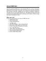
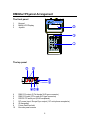
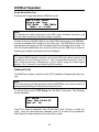
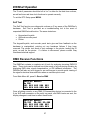
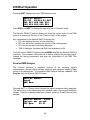
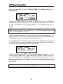
Gray Interfaces
DMXDart
Users Manual
August 2000.
1
Table of Contents
ABOUT DMX DART
5
WHAT CAN IT DO?
5
DMXDART PHYSICAL ARRANGEMENT
6
THE FRONT PANEL
THE TOP PANEL
THE REAR PANEL
INCLUDED ACCESSORIES:
OPTIONAL ACCESSORIES:
6
6
7
7
7
QUICK START
8
NAVIGATING THE MENUS
CONTROLLING DIMMERS
8
9
DMXDART OPERATION
10
MENUS
NAVIGATING THE MENUS
10
10
FUNCTION SUMMARY
10
MENU 1
MENU 2
10
11
GETTING STARTED
12
JOYSTICK
12
TRANSMITTING DMX
13
CHANGING THE DMX TRANSMIT MODE
13
ADVANCED DMX512 TRANSMIT OPTIONS
14
TRANSMIT S ETUP
1 - %/D EC
14
14
2
Table of Contents
2 – H EX
3 – BUMP
4 – POWER UP
5 – PARAMETERS
15
15
15
16
PRINTING DMX DATA
16
MOVING LIGHT CONTROL
17
MOVING L IGHT S ETUP
MOVING L IGHT MODEL
DMX ADDRESS (DMX OFFSET)
GROUP OFFSET
TOTAL NUMBER OF MOVING L IGHTS
18
19
20
20
21
CONTROLLING MOVING LIGHTS
21
PAN / TILT S HORTCUT
BRINGING F IXTURES “HOME”
CONTROLLING DIMMERS WHILE IN MOVING L IGHT MODE
23
23
24
CUE MODE
24
MISCELLANEOUS TOOLS
24
TESTING CABLES
DOUBLE ENDED CONTINUITY TESTING
DOUBLE-ENDED DATA TEST
S INGLE E NDED DATA TEST
ONBOARD CLOCK
S ELF TEST
24
25
25
26
26
27
DMX RECEIVE FUNCTIONS
27
RECEIVE DMX ANALYZER
RECEIVE DMX S ETUP
F LICKER F INDER
PRINTING RECEIVED DMX D ATA
OSCILLOSCOPE S YNC
DMX 512 MONITOR
IDS TALKBACK
28
29
29
31
32
32
33
3
Table of Contents
INTERNAL UTILITIES
33
POWER MANAGEMENT AND BACKLIGHT
CHANGING THE BATTERY
34
35
SOFTWARE UPDATES
35
CONNECTING TO A PC
INSTALLING S OFTWARE UPGRADES
35
36
DARTFLASH
36
TECHNICAL SUPPORT
36
APPENDIX A – MOVING LIGHT LIBRARY
37
APPENDIX B: CONNECTOR PINOUTS
39
DMX512 – 5 PIN XLR MALE
RS232 PC COMM / E NCODER EXPANSION
DMX L OOPBACK TEST CONNECTOR
PORT –
APPENDIX C – TROUBLESHOOTING
RJ 45 F EMALE, 8 PIN
39
39
39
39
4
About DMX Dart
The Gray Interfaces DMXDart is a fully featured DMX test tool that incorporates
DMX reception and transmission tools, as well as a set of functions completely
dedicated to moving lights. Complete cue recording and playback features are
also provided so that the DMXDart can be used as a miniature standalone
controller or as an inline backup DMX source. The DMXDart’s features, as well
as its intuitive handheld design make it the ideal tool for theatre, concert touring,
and themed entertainment users.
What can it do?
A few of the things that you can use your DMXDart to do!
• Handheld lamp check
• Verify console output
• Control dimmers directly
• Test DMX cables
• View DMX levels as %, hex or decimal values
• Synchronize a DMX signal to an oscilloscope
• Control moving lights individually or in groups
• Test “in wall” DMX wiring
• “Tweak” DMX output parameters
• Print out reports (with optional printer)
• Analyze incoming DMX signals
• Act as a DMX “Flicker finder”
5
DMXDart Physical Arrangement
The front panel
1
2
3
Keypad
Backlit LCD Display
Joystick
The top panel
4
5
6
7
8
9
10
DMX 512 output (5 Pin female XLR type connector)
DMX 512 input (5 Pin male XLR type connector)
RS 232 PC serial port (RJ45 receptacle)
DC power Input / Scope Sync output (1/8” mini phone receptacle)
IR transmitter
Future DartFlash slot
Encoder panel mounts
6
The rear panel
11
12
13
Battery compartment
Reset switch
Belt clip mounting hole
Included Accessories:
•
•
•
•
Soft carry case 7702
Belt clip kit
PC adapter kit with RJ11 – RJ45 cable, and RJ11 to DB9 adapter
9 Volt AC adapter
Optional Accessories:
7704
DMXDart moving Light Encoder Panel
Ericom Powerterm Software
7
Quick Start
Turning on the DMXDart is as simple as pressing any of the 4 top row keys on
the keypad. When one of these keys is pressed, the DMXDart will power up in
the mode that it was in when it was turned off.
NOTE: The DMXDart may transmit DMX immediately upon power up.
Please insure that all equipment (such as moving lights) is safe prior to
starting
The PWR/BKLT key provides access to the DMXDart’s power management
features, as well as operation of the LCD display. Pressing the PWR/BKLT key
accesses the top-level power functions menu. This menu appears like this:
MENU-continue
OFF- power down
BKLT-backlight
view angle , more
From this display, pressing the MENU key returns to the previous menu.
Pressing the OFF key turns the unit off, and pressing the PWR/BKLT key toggles
the LCD backlight on and off.
NOTE:
The backlight is set to automatically turn off after 2 minutes of inactivity.
NOTE:
While this is the only menu that allows the operator to power down the DMXDart
it can be accessed directly at any time by pressing the PWR/BKLT key.
Navigating the menus
The MENU key, located in the top right corner of the keypad, is the key that
allows for the navigation through the DMXDart’s menu system. At any time
during operation of the DMXDart, the pressing the MENU key will exit a function
and display the associated function menu. Pressing MENU key while in a menu
screen will advance to the next page of the current menu.
To choose a function, press the number key that corresponds with the number
displayed beside the desired function. This will call the function, and jump
directly to the function screen. Repeated presses of the MENU key from within a
function submenu will rotate through the associated function menu, returning to
the function display.
8
QUICK START
Controlling Dimmers
From the main menu select screen choose 1 to load Main Menu 1. From Main
Menu 1, select 2 - Transmit DMX512. The DMX 512 transmit function is now
displayed:
Transmit DMX512
Data Entry
CH???
@??%
From this screen, standard level setting commands can be used to transmit DMX
dimmer levels. Enter 1 THRU 40 @ 30 OK. DMX channels 1 through 40 are
now being transmitted at 30%. Subsequent commands will pile on levels to
previous entries on a last take precedence basis while in data entry mode.
Enter 41 AND 75 @ 15 OK. DMX channels 41 and 75 are now being transmitted
at 15%, while channels 1 through 40 are held at 30%.
To blackout or turn all dimmers off, enter 1 THRU 512 @ OFF OK.
9
DMXDart Operation
Menus
The DMXDart’s operating software is a menu-based system that provides quick
access to all of the unit’s functions. The system consists of 2 main menus, one
for DMX transmit functions and one for DMX receive functions. From each of the
main menus, functions are chosen by pressing the number corresponding to the
item desired. To swap main menus, choose the ‘main menu select ‘ option from
either of the main menus. This will display the main menu selection screen:
Main Menu Select
1-Transmit Functions
2-Receive Functions
1 or 2 select
Pressing the 1 key from this menu loads main menu 1, and the 2 key loads main
menu 2.
Navigating the menus
The MENU key, located in the top right corner of the keypad, is the key that
allows for the navigation through the DMXDart’s menu system. At any time
during operation of the DMXDart, the pressing the MENU key will exit a function
and display the associated function menu. Pressing MENU key while in a menu
screen will advance to the next page of the current menu.
To choose a function, press the number key that corresponds with the number
displayed beside the desired function. This will call the function, and jump
directly to the function screen. To set up the parameters of any function, or to
access function options, press MENU from the function display. This will access
the function’s submenu. Repeated presses of the MENU key from within a
function submenu will rotate through the associated function menu, returning to
the function display.
Function Summary
Menu 1
1 - About Dart
Displays information about the DMXDart software, including software version,
and the software serial number.
2 - Transmit DMX512
10
DMXDart Operation
Command line setting of DMX levels. Controls conventional DMX equipment.
Transmits variable DMX ‘flavors’ for testing DMX reception equipment.
3 - Moving Light Tx
Dedicated control of moving lights, complete with fixture library, and attributes.
Encoders and integrated pointing device provide direct access to attributes.
4 - Cue Mode
Playback of cues in standard DMX or moving light mode. Also contains backup
mode for operation inline with a DMX console.
5 - Misc Tools
Cable tester, real time clock, and DMXDart self-test functions.
6 - Main Menu Select
Allows for the swapping of main menus between receive and transmit functions.
Menu 2
1-About DART
Displays information about the DMXDart software, including software version,
and the software serial number.
2-Receive DMX512
Analyzes incoming DMX signal for signal integrity, as well as displays all
incoming DMX data by channel. User configurable extended features include
alternate start codes, DMX termination, and pass-through regeneration.
3-DMX512 Monitor
Extends the Receive DMX functionality by displaying all signal parameters and
full 512 bytes of DMX data on a single display via connection to a PC.
4-IDS Talkback
Monitors and translates messages sent by products supporting DMX talkback on
pair 2 of the DMX cable.
5-Main Menu Select
Allows for the swapping of main menus between receive and transmit functions.
11
DMXDart Operation
Getting Started
Turning on the DMXDart is as simple as pressing any of the 4 top row keys on
the keypad. When one of these keys is pressed, the DMXDart will power up in
the mode that it was in when it was turned off.
NOTE: The DMXDart may transmit DMX immediately upon power up.
Please insure that all equipment (such as moving lights) is safe prior to
starting
Joystick
The DMXDart features an integrated pointing device located at the center of the
front panel. This device will respond to very small pressures applied to the entire
outside diameter, as well as straight downward. While it is the first instinct for the
user to press hard to create large changes in the on-screen values, it is actually
more effective to press lightly. Operating the pointing device very gently will give
the best results when operating moving lights, or manipulating values within other
menus.
If you are having difficulty with the joystick, try the following exercise:
Go to Main Menu 1. Choose 5 - Misc Tools, and then 3 - Misc. Self Test.
Finally press 1 – Keypad Joystick.
You should see something like this:
Keypad/Joystick
Keypad:
X:+001 Y:+003 Z:+000
press menu to exit
The part of the display that we are interested in for this exercise, are the X & Y
readouts. These show how much ‘action’ your joystick pressure is generating.
Give it a try using very little pressure. Observe just how little pressure it takes to
get a response. A little practice in this display should be all it takes to improve
your joystick technique.
12
DMXDart Operation
Transmitting DMX
The DMXDart supports 2 modes of transmitting DMX data, each having a
different application when testing a lighting system. The first mode is Data Entry
mode, which is more commonly referred to as command line level setting. In this
mode DMX levels are set using standard command line language through the
whole 512 channel DMX stream, and 512 channel ‘looks’ are established by
“piling on” levels. Channel levels are held at their last set level until they are
changed. The second mode is Channel Test, which allows for the sequential
testing of single channels, while leaving all others off. A single channel is
brought to a level using the standard command line, then the NEXT and PREV
keys are used to increment or decrement the channel number being tested. As
the channel is changed, the previously active channel is taken to 0.
Changing the DMX transmit mode
From the DMX transmit Function display press the MENU key. The Transmit
DMX Menu will be displayed:
Transmit DMX512
1-Main Menu
2-Ch test / Normal
3-Cue Mode
Press 2 - Ch Test/Normal to change the transmit mode. This will be displayed:
Transmit DMX512
CH Test/normal mode
Mode: Norm
^
Pressing the up or down arrow keys changes the mode. Press the Ý key. The
display will look like this:
Transmit DMX512
CH Test/Normal
Mode: Test
T:0.0
13
DMXDart Operation
Press the Ü key and enter 10. This will set the channel test to a 1.0-second fade
time. Press MENU then OK. This returns the Transmit DMX function display,
changed for channel test mode.
Transmit DMX512
Ch Test
CH ???
@ ??%
^
Enter 1 @ 75 OK. DMX channel 1 is now being transmitted at 75%. Channels 2
through 512 are off. Press NEXT. DMX channel 2 is now being transmitted at
75%, Channels 1 and 3 through 512 are off. Press PREV. DMX channel 1 is now
being transmitted at 75%. Channels 2 through 512 are off.
The Next and Previous keys can be used to sequentially check dimmers and
fixtures through all 512 DMX channels.
Data entry can also be used to check single DMX channels non-sequentially.
Enter 200 @ 90 OK. DMX channel 200 is now being transmitted at 90%, 1
through 199 and 201 through 512 are off.
Enter: 6 @ 80 OK. Channel 6 is now at 80%, and all other dimmers are off.
Advanced DMX512 Transmit Options
Transmit Setup
From the Main Menu, press 2-Transmit DMX512. This puts the DMXDart output
online. Press Menu again to enter the Transmit DMX512 Menu. Select 4-Tx
Setup for the Transmit Setup. This menu offers 5 options for customizing the
DMX512 Transmit function:
1 - %/Dec
Changes to display of DMX levels between percentage (00 to FL) or decimal (00
to 255). Use the Ý and Þ buttons to change the levels display mode, then press
MENU to return to the Setup menu. When in DMX Transmit mode, levels will
display with a % when in percentage mode, or without the % when in decimal
mode. Changing the way that levels display, also changes they way they are
entered from the keypad. Percentage display means levels can be entered from
the keypad using values from 00 to 100 (FL). Decimal display requires levels
with values from 00 to 255. The Ý and Þ keys can be used to change levels,
regardless of the display mode selected.
14
DMXDart Operation
NOTE: Changing the way that levels display, also changes they way levels
are entered from the keypad.
2 – Hex
This function adds the hexadecimal value of the level selected to the levels
display. When this method of display is selected, the hexadecimal level is shown
to the right of the (% or D) level display, next to the level information. The letter
H follows the hexadecimal level.
Transmit DMX512
Accepted
CH 001
@
16%
^
29H
Use the Ý and Þ buttons to turn the hexadecimal display mode on or off, then
press MENU to return to the Setup menu.
3 – Bump
Use this function to set the level and fade time parameters for the BMP (Bump)
key operation. Use the Ý and Þ or the keypad buttons to set the level you want
to bump to when the BMP button is pressed, then press Ü to move to the fade
time parameter (T:). Use the Ý and Þ buttons or the keypad to set the fade time
you want to use for the bump function. Any fade time from 0.0 to 9.9 seconds
can be set. Press MENU to return to the Setup menu.
4 – Power Up
When DMX transmit mode is selected, the DMXDart will output the DMX levels
present in last state that DMX transmit was in before it was powered down. A
Power Up fade time can be assigned to give the user an opportunity to either
pause the fade or take the DMXDart offline if the output state going live is not
what is desired.
Use the Ý and Þ or the keypad buttons to set the fade time you want, from 1 to
99 seconds. Press MENU to return to the Setup menu.
NOTE: As a precaution, the minimum power up fade time is limited to 1
second.
15
DMXDart Operation
5 – Parameters
1 – Type Setup: This selection allows you to configure the characteristics
of the DMX output signal. Sets the “flavor” of the DMX signal: A, B, C, or
U. A through C are factory defaults, and U is a user programmable type
for “tweaking” the DMX output. This can be especially useful in
determining why a device that is considered to be DMX does not respond
to a particular console
(More required… DAVE ??)
2 – Sync Setup: Turns on the Scope Sync port, and sets up the portion of
the signal to sync to. (See Rx Sync Test for further information)
3 – Data Loss Test: Intentionally transmits poor DMX signal, manipulated
by the user. Inserts 100ms to 2 s of “dead time” into the signal at a
specified point. Tests DMX reception equipment for its reaction to poor
data.
Printing DMX Data
Note:
Printing requires the optional Hewlett Packard 82240B Thermal Infrared printer.
From the Transmit DMX512 submenu, press 5 – Print DMX Data to enter the
print screen.
Transmit DMX512
Print Data
* Hexval CH:001-050
^
From this display, all of the print options are set. For example, to print the
decimal value of channels 1 to 400 press Ü to move the cursor (^) to below the
format setting (currently Hexval):
Transmit DMX512
Print Mode Select
* Hexval CH:001-050
^
16
DMXDart Operation
Press Ý to change the format to “Decimal”. Press Ü to move the cursor to the
beginning channel value:
Transmit DMX512
Print Range Select
* Decimal CH:001-050
^
Enter the lowest channel to be printed, in this case 1. Press Ü to move the
cursor to the highest channel value, and enter 400. Press Û twice to move the
cursor below the asterisk (*), position the printer in a direct line with the top panel
of the DMXDart, and press OK. The display will show:
Transmit DMX512
Printing:anykey-stop
* Decimal CH:001-050
^
To stop the print press any key, otherwise the full range specified, in this case
from channel 1 to 400, will print. To exit the Print DMX display, press MENU or
Û.
Moving Light Control
An advanced feature of the DMXDart is its ability to control a wide variety of
moving lights. The DMXDart contains a complete fixture library of approximately
189 fixtures, and incorporates a joystick and optional encoders for direct access
to moving light attributes.
To enter Moving Light Control (ML-Tx) mode select Main Menu 1 from the Main
Menu Select display. Press 3 - Moving Light TX.
The Moving Light transmit function display will load. During the load something
like this will be displayed:
Moving Light TX
Technobeam (full)
Encoders setup ok!
Note:
If the optional Encoder Wing is not connected, the DMXDart will automatically
disable encoder operation. To enable the Encoders, simply plug the Encoder
Wing cable into the DMXDart and reload the Moving Light TX function.
17
DMXDart Operation
After the function loads the display will change to something like this.
Pan Coarse
Grp
PanH PanL TiltH TiltL
000
000
000
000
^
C
This display is the Moving Light display, showing the first 4 attributes of the
selected moving light. This is the display where moving light control takes place.
Moving Light Setup
In Moving Light mode, the DMXDart controls up to 512 DMX channels, and each
channel controls one attribute of a moving light. Before using the DMXDart to
control moving lights, it must be set up for the specific number and type of
moving lights that are to be controlled.
Note:
Only 1 type of moving light may be controlled at a given time.
There are three aspects to DMXDart moving light configuration:
• Moving light model
• Address (address offset)
• Group offset
• Total number of moving lights
Different models of moving lights assign their attributes in a different order. In
addition, many models have attributes (color, gobo, strobe, etc.) that are not
found on other fixtures. To accommodate these differences, the DMXDart has to
know which model of moving light is being addressed so that it can map the attributes correctly. You will need to know the exact model of the moving lights you
need to control. See appendix “A” for a listing of moving lights.
The DMXDart needs the correct DMX address for the moving lights to ensure
that the luminaire is controlled correctly. Since most rigs have the moving lights
addressed in sequence, DMXDart follows this convention when configuring the
address range. You will need to provide the address of the lowest addressed
fixture in your rig before you can control any moving lights.
To simplify the moving light addressing process, the DMXDart is capable of
offsetting each moving light’s start address by a user programmable number of
channels (Group Offset). For example, if a moving light has 18 attributes, you
could separate each light’s start address by 20 channels. This will make it easier
to set the fixture addresses in the rig. Fixtures can be DMX addressed as
1…21…41…61 as opposed to 1…19…37…55.
18
DMXDart Operation
When actually controlling individual moving lights, they are called up as fixture
numbers. Fixture number 1 will be patched by the DMXDart to the fixture who’s
DMX address was set in the DMX offset. Fixture 2 will be patched to the address
calculated by using the Group Offset and the DMX Offset, and so on. This
patching process continues for the total number fixtures you have under your
control.
To enter the setup menu from the Moving Light TX display press MENU then 4Setup to enter the moving light setup submenu. Press 1 - Parameters to enter
the ML Parameters submenu.
Moving Light Model
To select the type of moving light being controlled, press 1 –ML# Select. You
should see something like this:
ML# Select
Technobeam (full)
Select ML:078 Att=18
^
The DMXDart fixture library assigns a unique number to each model of moving
light. To choose the model of moving light you wish to control, you have to select
its corresponding fixture number. To make this easy, The DMXDart displays
both the fixture number and the fixture model name on the moving light selection
display.
The cursor will appear under the moving light number. From this location a
moving light can be selected via direct digital entry or by using the Ý and Þ
keys. As the moving light numbers are scrolled through, the model and the number of attributes that fixture utilizes are displayed.
Once the desired moving light has been selected, Press MENU to return to the
ML Parameters submenu.
19
DMXDart Operation
DMX Address (DMX Offset)
NOTE:
Incorrect addressing can result in unpredictable moving light response to control.
From the ML Parameters menu, press 2- DMX Offset to enter the DMX Offset
display:
DMX offset
DMX offset 001
^
Enter the DMX start address for the moving light with the lowest start address
using the number keys or the up and down arrows.
Press MENU to save and exit to the ML Parameters submenu.
Group Offset
Note:
The group offset cannot be less than the number of attributes within the moving
light.
To change the group offset,
From the ML Parameters submenu, press 3 - Group Offset
Group Offset
Group Offset: 020
^
Enter the desired group offset using the number keys or the Ý and Þ keys.
Press MENU to save and exit to the ML Parameters submenu.
20
DMXDart Operation
Total Number of Moving Lights
From the ML Parameters submenu press MENU to access page 2 of the
submenu. Press 4 - # of lights/group
# of lights/group
Technobeam (full)
# lights/group:020
^
Enter the total number of moving lights being controlled (to a maximum of 512
DMX channels) using the number keys (followed by OK) or the up and down
arrow keys. Press MENU to save and exit to the ML Parameters submenu. Press
Menu 4 times to return to the ML TX function display.
Controlling Moving Lights
The DMXDart can control a single moving light within the group, as well as the
entire group.
When changing from single mode to group in Moving Light TX, the DMXDart,
regardless of what is being transmitted, synchronizes the attributes of all of the
moving lights in the system. Attributes are moved to the last values set in Group
Mode. Each time the mode is switched from Group to Single, the DMXDart saves
the last levels transmitted to the whole group of fixtures.
When Group Mode is re-selected, the DMXDart reminds the user that the last
group data will be restored, reverting all of the channels that were changed in
single mode.
There is currently no method of re-entering group mode without restoring the
levels.
Operational Tip:
Set all group options first: set color and gobo information for all fixtures in Group
Mode prior to setting each individual fixture’s position, focus etc.
21
DMXDart Operation
From the Moving Light TX function display, press 2 - SGL / Grp to enter the
setup display:
SGL/GRP setup
Mode Select
Mode: group
^
Use the Ý and Þarrows to change from Group to Single mode. Press OK.
display will change to:
The
SGL/GRP setup
Sgl # within group
Mode: single: 012
^
Press Ü to move to the fixture number and use the Ý and Þ keys or direct
numeric entry to select the desired fixture number. Press MENU to complete the
selection and return to the Moving Light TX function display.
The top right corner of the display will show whether a single moving light or the
entire group of moving lights is being controlled. If group operation has been
selected, “grp” will be shown. If a single fixture is being controlled, the number of
the fixture will be displayed.
Once the correct moving light has been selected (in this case ML# 78 – HES
Technobeam) attributes can be directly controlled using the Ý and Þ keys,
encoders, or direct digital entry. The joystick is automatically assigned to the pan
and tilt attributes.
To select an attribute, use the Û and Ükeys to move the cursor (^) beneath the
desired attribute. To quickly scroll through pages of attributes, simply press the
NEXT and PREV keys. Once the desired attribute has been selected, values
may be manipulated using the number keys (followed by OK) or Þ and Ý keys.
Regardless of the attribute menu being displayed, the joystick will always operate
the pan and tilt attributes.
22
DMXDart Operation
Pan / Tilt Shortcut
The Pan / Tilt Shortcut gives instant visibility and control of the three most
commonly used moving light attributes; pan, tilt and intensity. This display can
be accessed by simply pressing the @ key from the moving light control display.
When Pan / Tilt mode is active, a P/T will appear in the upper left corner.
P/T
PanH PanL TiltH
000
000
000
^
Grp
TiltL
000
C
This shortcut menu gives instant access to the optional Encoder Panel for pan
and tilt. In P/T Mode the Bump key flashes the fixture to full while the key is
depressed.
Another use of the Pan / Tilt Shortcut is to change the fixture being controlled in
“single” mode. While the P/T display is active, pressing NEXT and PREV steps
the live fixture number, speeding up the programming process.
To exit the pan/tilt shortcut, press @ again.
Bringing Fixtures “Home”
To speed up programming of moving lights, the fixture library contains a set of
default parameter values that put the fixture into a “home” position. Home is
typically 50/50 pan and tilt, no color, no pattern, 50% focus, iris and shutter open,
intensity at 0%, and all control parameters at “safe”. This gives a “clean slate” to
begin setting up looks.
The DMXDart will home either a single fixture or a group, depending on which
mode you were last in. From Moving Light Tx, select 6 – Home. DMXDart will
display a reminder if the home function is going to be performed on the entire
group of fixtures. Press OK to accept.
23
DMXDart Operation
Controlling Dimmers while in Moving Light Mode
The moving light TX submenu allows for the setting of DMX levels outside of
those channels used for moving lights. To set levels from the Moving Light Tx
function screen press MENU to enter the Moving Light Tx submenu. Press 3 DMX512 to switch to Tx mode. Enter DMX levels using the standard command
syntax, as outlined in the DMX512 Tx section of this manual. To return to the
Moving Light control display, press MENU, then 1 – Return to M/L Tx
NOTE:
This is a special mode of DMX512 transmit that allows fast switching between
DMX direct control and Moving Light control. The DMX 512 transmit options can
still be set up while operating in this mode.
Cue Mode
At the time of this manual’s publication, the cue mode remains under
development.
Watch the Gray Interfaces website for updates. Features to
include:
•
•
•
•
•
•
100+ Cues with memory backup
Fully programmable fade and wait times, as well as linking of cues.
Standard cue operation syntax.
RTC Mode
Backup Mode
Moving Light Mode ( With 16 bit support)
Miscellaneous Tools
The Misc Tools section contains 3 useful tools.
•
•
•
DMX cable tester
Set the DMXDart’s internal real-time clock.
DMXDart Self Test
Testing Cables
The DMXDart is able to test DMX data cables using 3 different methods:
•
Double ended continuity testing – checks the cable for shorts, opens, and
incorrect connections
24
DMXDart Operation
•
•
Double ended data loss testing – checks a cable for its’ data transmission
stability by connecting both ends to the DMXDart’s DMX input and output and
transmitting 250Kbps data over it.
Single ended loopback data loss testing – same as double ended data
loss testing, but it allows for testing of permanently installed cable through the
use of a loopback connector.
Double ended continuity testing
From Main Menu Select, choose 1- Transmit Functions.
Select 5 - Misc Tools
Press 1 - Cable Test.
The double ended continuity test will be displayed:
Cable Test
CM-CF
1-N 2-N 3-N 4-N 5-N
Err Err Err Err Err
^v mode,
menu-exit
Connect one end of a DMX cable to the DMXDart’s input and the other to the
DMXDart’s output. The display will change automatically as the real time test is
performed:
Cable Test
CM-CF
1-1 2-2 3-3 4-4 5-5
Ok
Ok
Ok
Ok
Ok
mode,
menu-exit
Incorrect connections, shorts, and opens will be displayed as an Err on the third
line of the display.
Double-ended data test
Pressing the Ý and Þ arrow keys switches the cable test mode.
Press the Ý key. The display will change to:
Cable test 00000
Double-end data
(2-3) OK
(4-5)OK
mode, clr-reset
During this test the DMXDart counts packets of data that have been transmitted
and received. If the DMXDart detects data corruption on either of the pairs, an
Err! Will appear beside the problem pair. (2-3) Denotes pins 2 and 3 of the DMX
cable, or pair #1, and (4-5) pins 4 and 5 – pair #2.
The error message is held until CLR is pressed to reset the test.
25
DMXDart Operation
Single Ended Data Test
Pressing the Ý again switches the DMXDart mode.
Cable test 00000
Single-end loop
(TxJ)NoRx
(RxJ)NoRx
mode, clr-reset
Note:
TxJ Denotes the cable connected to the DMX output (Female) connector, and
RxJ the cable connected to the input (male) connector.
Connect one end of a DMX cable to one of the DMX connectors on the DMXDart.
Connect a loopback XLR connector to the other end. The DMXDart should count
data packets and display an OK message beside the connection being used. As
with the double-ended data test, errors are held until the CLR key is pressed,
allowing very rapidly occurring errors to be displayed.
TIP:
To create a DMX loopback connector, use a 5-pin XLR style cable connector and
connect pin 2 to pin 4 and pin 3 to pin 5. This connects the transmit pair ( pins 2
and 3) with the receive ( talkback) pair ( pins 4 and 5) using the correct signal
polarity. Pin 1 (Ground) is not tested using this method.
Onboard Clock
The DMXDart contains a real time clock (RTC) capable of displaying the day and
time.
Note:
This clock governs all fade operations within the DMXDart, and can be turned off,
subsequently disabling all fade functions within the unit.
To set the clock, enter 2- RTC Setup from the Misc Tools menu. The following
will be displayed:
RTC Setup
Time: Mon 16:48.57
Control: On
^
Press Ý to select a parameter, then Ü and the Ý and Þ keys to modify the
value. Once the value has been changed, press Û to return to the parameter
field. Repeat for each parameter that you wish to modify.
26
DMXDart Operation
The ‘Control’ parameter should be left at “on” to allow for the fade time routines,
as well as future real time clock functions to operate correctly.
To exit the RTC Setup press MENU.
Self Test
The Self-Test function runs diagnostic routines on 3 key areas of the DMXDart’s
hardware. Self Test is provided as a troubleshooting tool in the event of
suspected DMXDart malfunction. The areas tested are:
•
•
•
Keypad and Joystick
Optional encoder panel
Printer
The keypad/Joystick, and encoder panel tests give real time feedback as the
hardware is manipulated, pointing out any hardware failures if they have
occurred. The printer test sends a test message to the printer, testing the IR
ports, as well as the printer. If a failure is discovered, please contact Gray
Interfaces technical support.
DMX Receive Functions
The DMXDart contains a complete set of tools for analyzing incoming DMX512
data. These tools can be tailored to suit the needs of a given testing situation by
displaying DMX data, signal characteristics, or IDS talkback information. The
DMXDart will also act as a trigger for an oscilloscope to provide quick viewing of
the signal’s electrical characteristics when an oscilloscope is used.
From Main Menu #2, press 2 - Receive DMX
Receive DMX512
No RX!
001 002 003 004 005
00% 00% 00% 00% 00%
Once a lighting console, or any DMX 512 transmitting device is connected to the
5 pin XLR male connector on the unit’s top panel, and DMX levels are sent, the
display changes in real time to reflect those levels:
Receive
PS:512
001 002
20% 00%
DMX512
PR:041 SC:000
003 004 005
50% 00% 00%
27
DMXDart Operation
Pressing NEXT displays the next 5 DMX dimmer levels:
Receive
PS:512
006 007
20% 00%
DMX512
PR:041 SC:000
008 009 010
00% 00% 00%
Press PREV and NEXT to display the desired block of 5 dimmer levels.
The Receive DMX512 function display will show the current status of the DMX
signal it is receiving in the form of the 3 items on line 2 of the display.
Key components of the Receive DMX512 display are:
• PS is the data packet size, in bytes (dimmers)
• PR is the data rate in packets per second of the incoming data
• SC is the current start code being displayed
• TRM, if displayed, indicates that DMX line termination is ON
From the receive DMX512 display pressing MENU displays the Receive DMX512
submenu. This submenu offers options to further analyze the incoming signal,
change the testing parameters, and alter the functionality of the DMX Thru
connector.
Receive DMX Analyzer
This function performs a complete analysis of the incoming signal’s
characteristics, and can report average, minimum, and maximum values for each
portion of the data stream. To access the DMX Receive Analyzer, select 2 – Rx
Anaylzer from the Receive DMX512 menu.
Receive DMX512
Break
BRK Nom:
^
Pressing the Ý or Þ arrow keys changes the signal parameter being analyzed.
The second line of the display gives the complete name of the signal parameter
chosen. Once the parameter has been chosen, pressing Ü starts the real time
analysis.
Receive DMX512 00010
Packets per second
PPS Nom:
44.11
^
28
DMXDart Operation
The packet counter (top right of the display) begins to count the DMX data
packets received. To cycle the display between the minimum, nominal (average)
and maximum values, press the Ü key to move the cursor below the value being
received. Then press the Ý or Þ to change to the desired parameter.
The parameters that can be analyzed are:
BRK – Break Length
MAB – Mark after break
MBF – Mark Between Frames
MBP – Mark between packets
BTB – Break to Break
FPP – frames per packet
PPS – packets per second.
If the parameter being analyzed is outside of the recommended specification for
USITT DMX512-1990, an error message will be displayed beside the abnormal
value.
TIP:
For more information on DMX characteristics, please refer to United States
Institute for Theatre Technology DMX512/1990 Digital Data Transmission
Standard for Dimmers and Controllers. This publication is available for purchase
at http://www.usitt.org
Receive DMX Setup
Within Rx Setup, 3 parameters can be adjusted to tailor the way DMX receive
functions display and operate.
•
•
•
Start Code Select – View data for a single, user defined, start code
Termination – Turn on DMX termination when the DMXDart is the last
DMX receiving device in a daisy chain.
Thru-trans control – Set the output port (DMX thru) off, as a direct pass
through, or transmit a regeneration of the incoming signal. When
regenerating the signal, the DMX “flavor” can be chosen, effectively acting
as a DMX to DMX converter.
Flicker Finder
The Flicker Finder is a long-term test designed to detect fluctuating levels
(corrupt data) within a static DMX512 signal. The test compares a snapshot, or
individual packet of DMX512 levels against every incoming packet, and displays
inconsistencies. To test a DMX transmission device for “flickers”, go to DMX
transmit mode (Main Menu 1) and set a static look of DMX Levels such as 1-512
@ 50.
29
DMXDart Operation
Next, go to Main Menu 2, select 2- Receive DMX. Press Menu and select 4 –
Flicker Finder.
Flicker Finder
1- Snapshot
4- Test
2- Clear Log 5- Print
3- View
6-Setup
Connect the DMX source to be tested to the DMX input of the DMXDart.
Snapshot the levels by pressing 1 on the DMXDart, then OK. The unit will
prompt for confirmation of the snapshot (SURE??). Press OK a second time to
confirm.
Note:
DMX must be present for Flicker finder to run. If no DMX is present, you will be
returned to the Snapshot?? screen.
Once the snapshot has been taken, the Flicker Finder menu will reappear. To
perform the test, insure that the levels coming from the device have not been
inadvertently changed, and press 4 – Test to begin the test.
The Flicker Finder will continually analyze the incoming signal until the user stops
it. Each flicker or error found is logged and the first and last dimmer, as well as
the number of dimmers displaying errors will be shown:
Flicker Finder
First:???
Last:???
Test:00010
#Dim???
^
To stop the testing, press OK. The Flicker Finder Menu will reappear. To view
the log, press 3 - View, then 1 - Log. Use the Ý and Þkeys to scroll through the
errors. If Timestamps is selected from the View Select, the time of day for each
flicker found can be seen. The flicker log can also be printed using the optional
printer and selecting option 5 – Print. The print option prints the entire log by
pressing OK.
Note:
Print functions require a Hewlett Packard 82240B Thermal Infrared printer.
30
DMXDart Operation
Printing Received DMX Data
From the Receive DMX512 submenu, the incoming DMX data stream can be
printed using the Print Rx Data option.
From the Receive DMX512 submenu, press 5 – Print Rx Data.
Receive DMX512
Print Data
* Hexval
CH:001-050
^
From this display, all of the print options are set. For example, to print the
decimal value of channels 1 to 400 press Ü to move the cursor (^) to below the
format setting ( currently Hexval):
Receive DMX512
Print Mode Select
* Hexval CH:001-050
^
Press Ý to change the format to “Decimal”. Press Ü to move the cursor to the
beginning channel value:
Receive DMX512
Print Range Select
* Decimal CH:001-050
^
Enter the lowest channel to be printed. In this case channel 1. Press Ü to move
the cursor to the highest channel value, and enter 400
Press Û twice to move the cursor below the asterisk (*), position the printer in a
direct line with the top panel of the DMXDart, and press OK. The display will
show:
Receive DMX512
Printing:anykey-stop
* Decimal CH:001-050
^
To stop the print press any key, otherwise the full range of channels 1 through
400 will print. To exit the print RX Data display, press MENU.
31
DMXDart Operation
Oscilloscope Sync
The DMXDart provides oscilloscope users with a handy tool that will help
synchronize an oscilloscope’s display with characteristics of the incoming DMX
data stream. The Rx Sync test transmits a high-speed pulse from the 1/8” TRS
jack on the top panel of the DMXDart. Using this feature requires an adapter
cable (not included) to connect to the trigger input or alternate channel of an
oscilloscope. The pin-out is as follows:
Tip = Ground
Ring= Sync
Sleeve=Power supply input
The sync pulse is a 1uS wide 4V peak pulse that is output whenever the given
signal parameter is present.
Note:
An oscilloscope faster than 16MHz is required for an accurate look at the DMX
signal.
To sync a scope to the incoming signal, connect the scope’s trigger input and
ground to the scope sync adapter. Connect the scope’s primary probe to the
RX+ or – (pin 1 or 2 on the DMX input) and the reference to the shield of the
incoming cable. Enter the RX sync test function by selecting 6 – Rx Sync Test
Mode from the Receive DMX512 submenu:
Rx Sync Test Mode
Disabled
Sync:
Off
^
Use the Ý and Þ keys to choose the portion of the signal to synchronize to. The
available characteristics are:
•
•
•
Break,
Start Code
Any frame of data (1 to 512)
The sync port provides technicians with a means to obtain a quick and easy look
at the electrical characteristics of the incoming signal.
DMX 512 Monitor
AT THE TIME OF THIS MANUAL’S PUBLICATION, THIS FEATURE IS STILL UNDER DEVELOPMENT . DMX
MONITOR WILL PROVIDE A REAL-TIME DISPLAY OF 512 DIMMER LEVELS, AND DMX SIGNAL
CHARACTERISTICS VIA SERIAL CONNECTION TO A PC RUNNING E RICOM POWERTERM ™ 32
SOFTWARE.
32
DMXDart Operation
IDS Talkback
The IDS talkback function accepts status data from dimmers, color scrollers, and
other IDS-capable equipment over pair 2 of the DMX cable. When active this
display shows “raw data” from any devices communicating over the alternate
pair:
IDS Talkback: Control
Generic ID: 000 R:
G: 001
B: 001:
^
<Tx
From this display, dimmer levels can be set, and status messages returned can
be viewed. To set dimmer levels, press Û to go to the DMX-512 Tx (transmit)
display. Levels can be set using the usual command line entry, or via channel
test mode. Returning to talkback is achieved by pressing MENU 1. Any
incoming status messages will be displayed.
Please consult the equipment’s manufacturer for IDS “plain English” data
translations.
Internal Utilities
The DMXDart contains a menu designed specifically for internal utility functions –
functions that do not relate to the analysis of DMX equipment. This menu is
called the BOOT menu. To enter the boot menu, first turn the DMXDart off.
While holding the 4 key, press PWR. This will load the boot menu:
Boot VerA.23
1-About Dart
2-Main Menu Select
3-PC Communications
This menu performs all of the functions with regards to operating software
installation and backup.
33
DMXDart Operation
Power Management and Backlight
The PWR/BKLT key provides access to the DMXDart’s power management
features, as well as operation of the LCD backlight. Pressing the PWR/BKLT
key accesses the top-level power functions menu.
MENU-continue
OFF- power down
BKLT-backlight
view angle, more
From this display, pressing the MENU key returns to the previous menu.
Pressing the OFF key turns the unit off, and pressing the PWR/BKLT key toggles
the LCD backlight on and off.
NOTE:
The backlight is set to automatically turn off after 2 minutes of inactivity.
NOTE:
This is the only menu that allows the operator to power down the DMXDart. This
menu can be accessed directly at any time by pressing the PWR/BKLT key.
The PWR/BKLT key also provides access to the DMXDart’s power management
software. The DMXDart has been designed to achieve the highest possible
operating time using a standard 9-volt battery. The power management software
tracks battery life, and calculates the time remaining. DMXDart’s power
consumption monitoring can also be used as a DMX troubleshooting tool.
Excessive power consumption during DMX transmit functions can be an
indication of cable problems.
From the power management screen, pressing Ü to access the Battery Status
display:
Battery Status
V=9.0 I=058mA C=100%
Run Time: 008hr 55min
MENU-exit
<more>
This display provides the following real-time information about the unit’s battery:
V
I
C
Run Time
Battery Voltage
Current draw in milliamps
Battery capacity remaining
Approximate available battery life
34
DMXDart Operation
By monitoring the battery status display, problems present in cabling or DMX
reception equipment may be discovered. The DMXDart’s power draw is typically
between 28 and 80mA, depending on a number of operational factors. Seeing a
current draw outside of this range indicates a problem somewhere in the signal
path and may prompt the use of another of the DMXDart’s DMX analysis tools.
Changing the Battery
The DMXDart’s run time and capacity are based on the typical current capacity of
a standard 9V Alkaline battery (approximately 540mAHr). Each time the
DMXDart’s battery is changed, this capacity must be reset to insure the most
precise calculations for these values. The DMXDart will automatically detect a
battery change and reset the capacity. You will be prompted to confirm a battery
change when one occurs.
Initial MAHR: 0540
Current MAHR: 0100
SET, FULL -– reset
MENU-exit
Back<
It is possible to change the initial capacity if a non-standard battery is being used.
This is done by using the up and down arrows to manipulate the value. Please
consult your battery’s manufacturer for the correct capacity information.
To exit the power management displays, press MENU. This will return to the
previously used function menu.
Software Updates
DMXDart software updates are available from the Gray Interfaces website
(http://www.gray-interfaces.com) as they become available. Software updates
will generally add features or enhancements, improve usability or fix bugs.
Connecting to a PC
To install the update, the DMXDart is connected to your PC using the supplied
serial cable. PC communications for the purpose of software updates are set up
from the PC Communication option within the boot menu. The DMXDart employs
a high-speed serial interface that can be configured to communicate using any
standard baud rate and settings. Choosing 1 – PC Comm Setup from the PC
Communications option sets up the port. The typical settings for software
updates are:
35
DMXDart Operation
Format: 8N2 (8 data bits, no parity, 2 stop bits)
Baud: 115.2Kbps
Choosing 2 – PC comm test, and pressing OK can test the connection. A
message will be sent to the PC, and will be displayed on the terminal screen of
any standard communication software, such as Hyperterminal. If the message
does not appear correctly, ensure that the communications settings of both the
PC and the DMXDart are identical. If the settings are the same and problems
still exist, try changing the values until the test is successful. For further
assistance, contact Gray Interfaces Technical support.
Installing Software Upgrades
To update the operating software, choose 4 – Update From PC form the Boot
menu. This will display the update screen. Follow the instructions provided with
the operating software package to download the software files to the DMXDart.
The software files will load, and will be scanned for corruption. If the software is
free of errors, the DMXDart will be ready to operate using the new software. To
restart the DMXDart, select 7-Restart. The DMXDart will start with the new
software.
DartFlash
At present, the DMXDart supports the use of a 128KB serial flash module for
software backup. Supplies of this module have become unreliable. Watch the
Gray Interfaces website for developments.
Technical Support
For technical support contact:
Gray Interfaces
480 C – 36 Avenue SE
Calgary, Ab.
T2G 1W4
Phone: +1 (403) 243-8110
Fax: +1(403)287-1281
E-mail: [email protected]
Internet: http://www.gray-interfaces.com
36
Appendix A – Moving Light Library
048: EC-1
049: Studio Spot
050: Studio Spot 575 CMY
051: Cyber M2 Litho
052: Technibeam Hi
053: Technoray
054: Technopro
055: Intellabeam 13 Ch
056: Dataflash
Amptown
001: Amptown Posi-Fan
002: Amptown PML Mk2
003: Amptown Washlite Hal
004: Amptown Washlite-HP
005: Amptown Wash-Shutter
Clay Paky
006: Superscan Zoom
007: Superscan Zoom Ext
008: Goldenscan HPE
009: Goldenscan 3
010: Goldenscan 2
011: Stagescan
012: Stage Light 300
013: Stage Color 300
014: Stage Color 575
015: Stage Color 1000
016: Stage Color 1200
017: Stage Zoom 1200
018: Goldenscan 3x
019: Super MRG
020: Superscan
021: Minihpe
022: Combicolor
Irideon (ETC)
065: Irideon AR5 Hi8Ch
066: Irideon AR500
Martin Professional
075: Roboscan 218
076: Roboscan Pro 218 M1
077: Roboscan Pro 218 M2
078: Roboscan Pro 218 M3
079: Roboscan 518
080: Roboscan Pro 518 M1
081: Roboscan Pro 518 M2
082: Roboscan Pro 518 M3
083: Roboscan Pro 812 M1
084: Roboscan Pro 812 M2
085: Roboscan Pro 812 –5C
086: Robo Pro1220 CMYR M2
087: Robo Pro1220 CMYR M3
088: Robo Pro1220 CMYR M4
089: Robo Pro 1220 XR M3
090: Robo 1220 RPR M2
091: Robocolour Pro 400
092: Robocolour Pro 4
093: Pal 1200 M1
094: Pal 1200 M2
095: Pal 1200 M3
096: Mac 600 M1-8 wo spd
097: Mac 600 M2 - 16 wo spd
098: Mac 600 M3 – 8 w spd
099: Mac 600 M4 – 16 w spd
100: Mac 500 M1-8 wo spd
101: Mac 500 M2 - 16 wo spd
102: Mac 500 M3 – 8 w spd
Coemar
030: CF1200HE
031: Nat 1200
032: Nat 2500
033: Samurai
High End Systems
040: Cyberlight
041: Intellabeam 700HX
042: Studio Color
043: Trackspot
044: Technobeam (full)
045: Technobeam (reduced)
046: Studio Spot 250
047: Studio Color 250
37
Appendix A – Moving Light Library
103: Mac 500 M4 – 16 w spd
104: Mac 1200 M1-8 wo spd
105: Mac 1200 M2 - 16 wo spd
106: Mac 1200 M3 – 8 w spd
107: Mac 1200 M4 – 16 w spd
108: Robo Pro 918 M1 - 8 wo spd
109: Robo Pro 918 M2 – 16 wo spd
110: Robo Pro 918 M4 – 16 w spd
111: Robo 918 M2
112: FxPal 1200 M2
144: VL5 M2-8BE
145: VL5 M3-16R
146: VL5 M4-16E
147: VL5 M5-8B
148: VL5 M6-16B
149: VL6 M1 –8R
150: VL6 M2-8E
151: VL6 M3-16R
152: VL6 M4-16E
153: VL6 M5-8B
154: VL6 M6-16B
155: VL7 –16 M6
156: VL5 M3
157: VL6 M3
158: VL7 5.0 M7
159: VL7 5.0 M8
160: VLM M1
161: VLM M2
162: VLM M3
Pani
120: Pani AMD15 + Shutter
121: Pani Projector & Sld
Sagitter
125: Sagitter Infinity
126: Sagitter Prince
127: Sagitter Digiflash
Other Manufacturers
175: Dimmer
176: Non Dimmable
177: Scroller
178: Scroller Dim
179: CMY Fader
180: CMY Fader / Dimmer
181: Strobe Dimmer
182: American DJ
183: Color Fader 300
184: Digital Beam Light
185: LT Komplett
186: Summa HTI
187: Statos Hires
188: Giant 16 Ch
189: Starlite MK5
Strand Lighting
130: PALS Pirouette
131: PALS Pirouette 16
132: PALS Pirouette Color
133: PALS Pirouette 16C
134: Hyperbeam 1288 CMYR M3
135: Hyperbeam 1200 XR M3
136: Hyperbeam 200
137: Colourbeam 200
138: Cadenza PC PALS
139: Cadenza 17/32 PALS
Vari*Lite
140: VLM M1
141: VLM M2-8BE
142: VLM M3-16B
143: VL5 M1-8BR
38
Appendix B:
Connector Pinouts
Appendix C –
Troubleshooting
DMX512 – 5 Pin XLR Male
Before contacting Gray Interfaces
Technical Support, please use the
following checklist to troubleshoot
DMXDart Operation Problems:
Pin
1
2
3
4
5
Function
Ground
Data TxData Tx+
Data RxData Rx+
Problem:
Unit not responding to Keypad
commands
Possible Solutions:
Power / Sync – 1/8 “ TRS
Tip
Ground
Ring
Sync
Sleeve Power
1) Disconnect Encoder wing and
repeat keypress
2) Manipulate Pointing device (
Lightly!) then repeat keypress.
3) Using a paperclip or piece of
wire, press RESET on rear of
unit.
RS232 PC Comm / Encoder
expansion port – RJ 45
Female, 8 pin
1
2
3
4
5
6
7
8
Problem:
Pan/tilt movement is very slow using
joystick
Encoder 1
Encoder 2
Encoder 3
Ground
Ground
RS232 CTS
RS232 TXD
RS232 RXD
Possible Solutions:
1) Check Lower Right corner of
display for “F” . “F” denotes
fine
movement,
and
is
switched by pressing directly
down on the pointing device
2) After switching the coarse/fine
mode, operate the pointing
device by pressing VERY
LIGHTLY on the unit. The
IPD is much more effective if
operated from the side, rather
than the top of the device.
Pressing hard on the device
may impede the device’s
function, or cause permanent
damage to the unit.
DMX Loopback Test
Connector
Using a single male or female 5-pin
XLR inline connector, connect as
follows:
Pin
1
2
3
Connected to Pin
NC
4
5
39
Problem:
Coarse / Fine selection not available
Possible Solutions:
1) IPD Range set to OFF in MLTx Setup submenu.
Turn
range ON to activate FINE
mode availability.
40