1
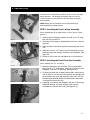
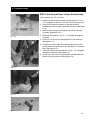
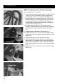
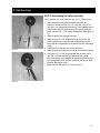
Cybex 600H Hiker Service Manual
Cardiovascular Systems
The 600H
Service Manual
The 600H measures, monitors, and
motivates your fitness and health.
SM-15649 Rev A
Cybex International, Inc.
10 Trotter Drive, Medway, Massachusetts 02053 USA
PREFACE
Read all instructions before using. Save These Instructions.
! WARNING: SERIOUS INJURY COULD OCCUR IF THESE PRECAUTIONS ARE NOT OBSERVED
DO obtain a medical exam before beginning any exercise program.
DO keep children away from the Hiker. Teenagers and disabled persons must be supervised while using.
DO set up and operate the Hiker on a solid, level surface. DO NOT operate in recessed areas or on plush carpet.
DO provide adequate clearance to the side, front, and back of Hiker. This should be a few feet from walls
and furniture and allow for safe access and passage around the machine.
DO NOT operate in damp or wet locations.
DO NOT use the Hiker outdoors.
DO NOT operate the Hiker around or where aerosol (spray) or where oxygen products are being used.
DO read the Owner's Manual completely before using the Hiker.
DO read all warnings posted on the Hiker.
DO inspect all belts and connections before each use. DO NOT use until worn or damaged parts are replaced.
DO NOT wear loose or dangling clothing while using the Hiker.
DO keep all body parts, towels, water bottles, and the like free and clear of moving parts.
DO use support devices at all times. These include the front, hand and side rails.
DO stop exercising if you feel faint, dizzy, or experience pain at any time while exercising and consult
your physician.
DO maintain and replace parts regularly. Refer to the Owner's Manual for detail.
DO use Cybex factory parts when repairing the Hiker.
DO call Cybex for technical support before attempting to perform any procedure that you are unsure about.
DO follow instructions in Service Manual for disassembly and assembly, when required.
DO NOT modify the Hiker in any way.
DO NOT use attachments not recommended for the Hiker.
DO replace any warning label if damaged, worn or illegible.
DO report any malfunctions, damage or repairs to the facility. (Commercial Equip.Only)
DO NOT use the Hiker if you exceed 350 lbs. This is the maximum rated user weight.
DO NOT install in a commercial setting. For consumer use only. (Consumer Equip.Only)
WARNING: Changes or modifications to this unit not expressly approved by the party responsible
for compliance could void the user’s authority to operate the equipment.
NOTE: This equipment has been tested and found to comply with the limits for a Class B digital
device, pursuant to Part 15 of the FCC Rules. These limits are designed to provide reasonable
protection against harmful interference in a residential installation. This equipment generates, uses,
and can radiate radio frequency energy and, if not installed and used in accordance with the
instructions, may cause harmful interference to radio communications. However, there is no
guarantee that interference will not occur in a particular installation. If this equipment does cause
harmful interference to radio or television reception, which can be determined by turning the
equipment off and on, the user is encouraged to try to correct the interference by one or more of the
following measures:
• Reorient or relocate the receiving antenna.
• Increase the separation between the equipment and receiver.
• Connect the equipment into an outlet on a circuit different from that to which the receiver is connected.
• Consult the dealer or an experienced radio TV technician for help.
Cybex and Cybex logo are registered trademarks of Cybex International, Inc.
DISCLAIMER: Cybex International, Inc. makes no representations or warranties regarding the contents
of this manual. We reserve the right to revise this document at any time or to make changes to the
product described within it without notice or obligation to notify any person of such revisions or changes.
© 2000 Cybex International, Inc. All rights reserved.
Printed in United States of America.
TABLE OF CONTENTS
1 INTRODUCING THE 600H HIKER BY CYBEX
Ergonomic Design
Warranty
Customer Service Hotline
3
3
4
2 DISASSEMBLY
Setup and Assembly
Choosing and Preparing a Site
Step 1 Removing the Shrouds
Step 2 Releasing Tension from the Linkage System
Step 3 Removing the Linkage System
Step 4 Disassembling the Tie Rod Assemblies
Component Parts of the Linkage System
Step 6 Removing the Pulley Assembly and Drive Belt
Step 7 Removing the Foot Plate
Step 8 Removing the Rear Pivot Arm Assembly
Step 9 Removing the Front Pivot Arm Assembly
Step 10 Removing the Front Linkage Assembly
5
5
5
5
6
6
7
8
8
9
9
10
3 INSTALLATION
Step 1 Installing the Front Linkage Assembly
11
Step 2 Installing the Front Pivot Arm Assembly
11
Step 3 Assembling the Short Linkage Rod Assembly
12
Step 4 Installing the Short Linkage Rod Assembly
13
Step 5 Installing the Rear Pivot Arm Assembly
14
Step 6 Assembling the Foot Plate Linage Rod
15
Step 7 Attaching a Foot Plate to the Front Pivot Arm Assembly 15
Step 8 Installing the Foot Plate Linkage Rod Assembly
16
Step 9 Assembling the Pulley Assembly
17
Step 10 Installing the Pulley Assembly
18
Step 11 Attaching the Drive Belt to the Foot Plate
18
Step 12 Installing the Long Linkage Rod Assembly
19
Step 13 Attaching the Drive Belt
19
Step 14 Attaching the Long Linkage Rod Assembly
20
Step 15 Installing the Long Linkage Rod Assembly
21
Step 16 Adjusting the Linkage System
22
Step 17 Adjusting the End of the Stroke
23
Step 18 Attaching the Shrouds
24
4 RETRO KIT INSTALLATION
Extract Calibration Settings
Display Panel Replacement
Replace Calibration Settings
Pulley Replacement
Error 3
25
25
26
26
27
5 DIAGNOSTICS
Display LED Test
Battery Test
Production Calibration Test
DVM Test
Static Diagnostic Check
28
28
28
28
29
6 DIAGRAMS
Parts List
Exploded View
Schematic
30
31
32
1
1 / INTRODUCING THE 600H HIKER BY CYBEX
600H Hiker™ by Cybex®
2
1 / INTRODUCING THE 600H HIKER BY CYBEX
The 600H Hiker by Cybex is a revolutionary new product which
defines a new exercise category. It is designed to provide the
commercial fitness facility and personal user with an effective tool for
total body conditioning. It utilizes a natural movement and provides
training variety with its intuitive display control and feedback. It is the
first and only product of its kind.
Ergonomic Design
If you improve your health, you
reduce the risk of certain chronic
degenerative diseases.
If you improve your
fitness, you can perform
moderate to vigorous
activity without undue
fatigue.
The 600H Hiker provides an upper and lower body workout in a
natural pattern that moves the way the body does. It combines the
advantages of a climber and an elliptical machine without any of the
disadvantages. Unlike most climbers’ pattern of movement which
moves the leg backward before it goes down, the 600H Hiker’s
pattern of movement moves the leg down as it goes backward. The
effect is to have a less acute angle at the knee during the exercise
and subsequently less stress in the joint than seen in current climbers
and steppers. In addition, unlike current climbers and elliptical pattern
products, the 600H Hiker’s pattern of movement works the gluteus
muscles harder and through a more complete range.
Unlike elliptical machines which have a fixed stride length, the 600H
Hiker has a user determined stride length. The user determines the stride
length and speed, and selects a resistance level which can simulate the
feel of an incline much like one would feel when hiking up a mountain.
The user can vary their stepping pattern throughout the workout without
having to make any adjustments to the machine. The width between the
pedals puts the user’s body in a position that is comfortable for the hips,
and the foot plates are angled to create a natural hiking motion.
Users have the option of using the ergonomically designed handles,
which are linked to the pedals. By having all four points- the two
pedals and two handles-linked, little coordination is required to
accomplish the total-body cardio workout.
The dual action 600H Hiker works the major muscles of both the
upper and lower body for an effective cardiovascular and fat-burning
workout. It spreads the workload over the body to help the user avoid
premature fatigue and discomfort. Users can choose the stride length
that fits as well as their relative upper and lower body involvement,
and can change it at any time. By varying movement pattern and
body position, users can tailor their workouts to emphasize particular
muscle groups or concentrate on sports-specific training.
The 600H Hiker has a belt drive for smooth, quiet operation, and a
cordless system with no power supply or plugs to worry about. The
center handles have built-in, hand-held heart rate sensors. The 600H
Hiker offers four motivational programs plus a manual mode.
Warranty
LIMITED WARRANTY TO NON-CONSUMER BUYERS: Seller warrants, to the
original Buyer only, that any product manufactured by it, herein listed under
"'EXPIRATION OF LIMITED WARRANTIES FOR NON-CONSUMER BUYERS,"
will be free from defects in material and workmanship, under normal use and
service according to the specified warranty duration listed, beginning from the
date of installation. Seller's obligation under this warranty shall be strictly and
exclusively limited to repairing or replacing parts and materials, free of charge,
3
1 / INTRODUCING THE 600H HIKER BY CYBEX
600H features include:
• Balanced total body involvement for a
better cardiovascular workout.
• “Free-stride” motion lets users
determine the most comfortable stride
length.
• Contact heart-rate monitor lets users
gauge the overall intensity of their
workout.
• Natural path of motion provides
balanced conditioning to the lower
body.
• Fluid motion of handles helps upper
body work efficiently.
• Self-powered unit can be placed
anywhere with no wires to trip over.
• Large worldwide dealer, sales, and
service network.
• Customer Service Hotline number:
Call 888-462-9239 in most areas.
Dial 508-533-4300 or
Fax 508-533-5183 in all other areas.
F.O.B. origin, which, in Seller's judgment are defective. Seller cannot control the
environment nor manner in which this is used, therefore this warranty does not
cover corrosion of product during use, or deterioration caused by conditions of
use, or that the application of finishes and/or cleaners are sufficient, or the
finishes and/or cleaners applied are suitable for Buyer's environment. Seller
does not warrant normal maintenance repairs such as identified within Seller's
Owner's Manual. Seller assumes no responsibility for repair or replacement
expenses incurred without it's prior written authorization. Buyer shall be
responsible for all labor costs incurred in connection with such repair or
replacement at the installation site unless agreed upon by Seller or covered
herein. All costs of removing, packing and shipping defective product and parts
shall be paid by the Buyer unless otherwise stated by the Seller. Seller's
authorized representative determines, in sole and final discretion that the nature
of the defect precludes remedy by repair or replacement of parts, Seller reserves
the right to satisfy its warranty obligation in full by refunding the full purchase
price upon return of all products to it, freight prepaid. The products or services
of other manufacturers which are furnished by Seller are covered only by such
warranties as are given by sold manufacturer to Seller. In the regard, Seller
agrees to certify to Buyer the identity of the supplier of items claimed to be
defective so that the Buyer may pursue warranty claims against that party.
EXPIRATION OF LIMITED WARRANTIES FOR NON-CONSUMER BUYERS:
Cybex Cardiovascular Products: Seller will warrant labor and parts for three
years. Refer to the "LIMITED WARRANTY FOR NON-CONSUMER BUYERS"
paragraph above for transportation cost responsibility and further explanation
of warranty coverage limitations and exclusions.
DISCLAIMER OF WARRANTIES AND LIMITATION OF REMEDIES:
SELLER MAKES NO OTHER WARRANTIES, EXPRESS OR IMPLIED, WITH
REGARD TO GOODS OR SERVICES PROVIDED BY SELLER OTHER THAN
THOSE SET FORTH HEREIN. ANY IMPLIED WARRANTY OF
MERCHANTABILITY OR FITNESS FOR A PARTICULAR PURPOSE OF BUYER
WHICH EXCEEDS THE FOREGOING WARRANTY IS HEREBY DISCLAIMED BY
SELLER. SELLER WILL NOT BE LIABLE FOR ANY DIRECT OR INDIRECT
CONSEQUENTIAL OR INCIDENTAL DAMAGES, LOSSES, OR EXPENSES,
INCLUDING, BUT NOT LIMITED TO COMMERCIAL LOSSES, BUSINESS
INTERRUPTION, OR DAMAGES RESULTING TO PROPERTY OTHER THAN
THAT WHICH IS THE SUBJECT OF THE SALES TRANSACTION.
ALTERNATIVE DISPUTE RESOLUTION FOR NON-CONSUMER BUYERS ONLY:
SELLER RESERVES THE RIGHT TO MANDATE INFORMAL DISPUTE
RESOLUTION TO SETTLE ANY OR ALL CLAIMS RESULTING FROM THIS
SALES TRANSACTION. ALTERNATIVE DISPUTE RESOLUTION PROCEEDINGS
WILL BE CONDUCTED IN THE STATE OF MASSACHUSETTS ACCORDING TO
THE COMMERCIAL RULES OF THE AMERICAN ARBITRATION ASSOCIATION.
It is understood between the parties that damage to product, ineffectiveness
of product, or other unintended consequences may result because of many
factors including the manner of use or application of the product, all of
which are beyond the control of the Seller. All such risks shall be assumed
by the Buyer.
PROCEDURE FOR OBTAINING WARRANTY PERFORMANCE:
To secure your warranty in event of a defect, contact the Cybex Customer
Service Department with questions regarding your warranty by mail or
telephone for instructions or a Return Authorization Number as provided below:
Cybex International, Inc., Attn: Customer Service Department
10 Trotter Drive
Medway, MA 02053
Tel: 1-888-462-9239
4
2 / DISASSEMBLY
Set up and Assembly
Setting up the 600H Hiker by Cybex is straightforward. Before you
unpack the machine, however, be sure to select a suitable site.
Choosing and Preparing a Site
Fig. 2-1
The area that you select for your 600H Hiker should be well-lit and
well-ventilated. Locate the 600H Hiker on a structurally sound and
level surface (do not place in recessed areas or on plush carpet) a
few feet from walls and other equipment. Allow for safe access and
passage during use of the machine. If the 600H Hiker is located
above the first floor, place it near or above major support beams. If
the area has a heavy plush carpet, the airflow around the base of the
unit may be restricted or the carpeting may interfere with the moving
parts. To protect the carpeting and the machinery, you can place a
3/4” (1.9 cm) thick wood or rigid plastic base under the 600H Hiker.
Do not install the 600H Hiker in an area of high humidity, such as
the vicinity of a steam room, sauna, or indoor pool. Exposure to
intensive water vapor and/or chlorine could adversely affect the
electronics, as well as other parts of the machine.
Disassembly of the 600H Hiker can be unsafe if you don’t follow
directions. The following disassembly steps are listed in sequential
order. In some cases, you can ignore some steps. In those cases we
have listed the steps you must follow before further disassembly.
WARNING: It is very important to recognize that with few
exceptions the tension from the linkage system must be released
before continuation of disassembly. Safety glasses should be
worn while assembling or disassembling the linkage system.
Fig. 2-2
STEP 1-Removing the Shrouds
(Tools required–One Phillips head screwdriver.)
1. Locate and remove all 15 metal screws and washers.
2. Locate and remove two 10-32 x .50” long screws, one on
each side of the unit.
3. Locate and remove one 10-32 x .75” long screw, on the front
of the unit.
4. Slide the right side shroud up and over the handle.
5. Slide the left side shroud up and over the handle.
6. Push one pedal to the bottom of the stroke. Remove the
center shroud.
7. The Hiker should now look like figure 2-1.
Fig. 2-3
STEP 2-Releasing Tension from the Linkage System
(Tools required–One 5/16” Allen wrench, safety glasses.)
1. Position yourself straddling the side tube as shown in figure
2-2.
2. Grasp the long tie rod assembly with one hand and try to
rotate. You should feel resistance.
5
2 / DISASSEMBLY
3. Push the foot pedal backward with your foot (see figure 2-3)
until you can rotate the long tie rod assembly freely with
your hand.
4. Hold the foot pedal in this position and remove the 1/2-13 x
1.50” long screw. (See figure 2-2.)
5. Lay the long tie rod on the assembly floor.
6. Slowly and carefully, let the foot pedal come forward until
there is no force on the pedal.
STEP 3—Removing the Linkage System
Must complete at least Step 2-Disassembly.
(Tools required–Two 3/4” wrenches, one 5/16” Allen wrench, one
flat head screwdriver and safety glasses.)
Fig. 2-4
1. Remove the 1/2-13 x 2.00” long bolt and 1/2-13 lock nut on
the lower end of the long tie rod assembly.
2. Remove the 1/2-13 x 1.75” long bolts and two 1/2-13 lock
nuts on the short tie rod assembly.
3. Remove the 1/2-13 x 1.5” long screw on the foot plate tie
rod assembly.
4. Remove the retaining ring attaching the foot plate tie rod
assembly.
5. Remove the foot plate tie rod assembly.
WARNING: Be sure that tension from the linkage system has
been released prior or further disassembly.
STEP 4-Disassembling the Tie Rod Assemblies
Fig. 2-5
Must complete at least Steps 1,2,3-Disassembly.
CAUTION
Do not use any lubricant on
tie rod ends. Using lubricant
on tie rod ends can destroy
bearings and will void
warranty.
CAUTION
Use only Cybex replacement
parts when servicing. Failure to do
so could result in personal injury.
Cybex will void warranty if nonCybex replacement parts are used
or when unauthorized modifications
are made.
6
(Tools required–One 3/4” wrench, one 5/8” wrench.)
NOTE: The rod ends and check nuts on the front ends of the tie
rod assemblies are all left hand thread while the rod ends and
check nuts on the back ends are right hand thread.
1. While holding the tie rod, loosened the 1/2-28 check nut.
2. Screw out the rod end.
2 / DISASSEMBLY
14
9
Component Parts of the Linkage System
1. 1/2-13 x 1.75” long hex head bolt
2. 1/2-13 x 2.00” long hex head screw
3. 1/2-13 x 1.50” long BHC screw
11
4. 1/2-13 lock nut
5. 1/2-28 nut, left hand thread
6. 1/2-28 nut, right hand thread
10
7. 1/2” rod end with 1/2-28 left hand thread
8. 1/2” rod end with 1/2-28 right hand thread
Fig. 2-6
9. Short tie rod
10. Long tie rod
11. Foot plate tie rod
12. 1/2” flat washer
13. 1/2” ID spacer
14. 3/4” ID wear washer x 7
15. Retaining ring, foot plate tie rod
Fig. 2-7
Fig. 2-8
7
2 / DISASSEMBLY
WARNING: Be sure that tension from the linkage system has
been released prior to further disassembly.
STEP 6-Removing the Pulley Assembly and Drive
Belt
Must complete at least Steps 1,2-Disassembly.
(Tools required–One 1/8” Allen wrench, one 1/4” Allen wrench, one
9/16” wrench.)
1. Grasp the tension spring and pull down. (See figures 2-8
and 2-9.) Then slip the loop off of the spring shaft.
Fig. 2-9
2. Remove two 1/4” set screws from each of the belt retainers
at foot plate.
3. Slide the drive belt out through the pulley assembly.
4. Remove the 1/2 x .625” long shoulder screw.
5. Remove the pulley assembly. (See figure10.)
WARNING: Be sure that tension from the linkage system has
been released prior to further disassembly.
STEP 7-Removing the Foot Plate
Must complete at least Step 2-Disassembly.
Fig. 2-10
(Tools required–One flat head screwdriver, one rubber hammer.)
1. Remove the two retaining rings on the foot plate which
attach the foot plate to the rear pivot arm assembly. (See
figure 2-11.)
2. Remove the retainer from the foot plate tie rod found in rear
of pedal.
3. Slide the seven wear washers (not shown in figure), foot
plate and the belt attachment assembly off. This may require
a tapping with a rubber hammer.
Fig. 2-11
Fig. 2-12
8
2 / DISASSEMBLY
STEP 8-Removing the Rear Pivot Arm Assembly
Must complete at least Steps 2 and 7-Disassembly
(Tools required–One flat head screwdriver, two 1/2” wrenches.)
1. Remove both protective plastic caps.
2. Remove four 5/16 x .75” long screws and four 5/16 x .75”
locks nuts.
3. Slide off plastic cap brackets.
4. Slide off both bearing sets.
5. Rotate pivot arm assembly to remove.
Fig. 2-13
WARNING: Be sure that tension from the linkage system has
been released prior to further disassembly.
STEP 9-Removing the Front Pivot Arm Assembly
Must complete Steps 1,2,3,4-Disassembly.
(Tools required–Two 1/2” wrenches.)
1. Remove four 5/16-18 x .75” long screws and four 5/16-18
lock nuts. (See figure 2-15.)
2. Slide off both of the bearing sets.
Fig. 2-14
3. Rotate the pivot arm assembly to remove. Keep turning and
rotating until it slides out.
Fig. 2-15
Fig. 2-16
9
2 / DISASSEMBLY
STEP 10-Removing the Front Linkage Assembly
Must complete Steps 1,2,3,4-Disassembly.
(Tools required–One 9/16 deep socket, one 9/16 wrench.)
1. Remove one 3/8-16 x 3.75” long bolt and one 3/8-16 lock nut.
(See figure 2-17.)
2. Slide out the front linkage assembly. (See figure 2-18.)
NOTE: It is sometimes easier to see if you stand machine on its rear
legs.
Fig. 2-17
Fig. 2-18
10
WARNING: Be sure that tension from the linkage system has
been released prior to further disassembly.
3 / INSTALLATION
Installation of the 600H Hiker by Cybex can be unsafe if you don’t
follow directions. The following installation steps are listed in
sequential order assuming that the Hiker has been completely
disassembled.
NOTE: Safety glasses should be worn while assembling or
disassembling the Linkage System.
STEP 1-Installing the Front Linkage Assembly
(Tools required–One 9/16” deep socket, on 9/16” wrench, safety
glasses.)
Fig. 3-1
1. Select one front linkage assembly: One 3/8-16 x 3.75” long
bolt, one 3/8-16 lock nut.
2. Orient the front linkage in relationship to the unit as shown in
figure 3-1.
3. Align the holes in the bearing with the mounting holes in the
unit.
4. Slide one 3/8-16 x 3.75” bolt in from the top. Make sure the
wide spacing of the linkage assembly is on the bottom. (See
figure 3-2.)
5. Attach on 3/8-16 lock nut and tighten to 22 ft-lb minimum.
STEP 2-Installing the Front Pivot Arm Assembly
(Tools required–Two 1/2” wrenches.)
Fig. 3-2
1. Select the front pivot arm assembly. This is comprised of
four 5/16-18 x .75” long screws, four 5/16-18 lock nuts, four
flangettes, and two 1” ID bearings. (See figure 3-3.)
2. To rotate the pivot arm assembly into position, keep turning
until it slides in. Put one pivot shaft of pivot arm through one
pivot bracket, then twist and rotate the shaft until it fits into
the other pivot bracket. Make sure the bumper attachment
is towards the front of the unit.
Fig. 3-3
3. A bearing set contains two flangettes and one 1” ID bearing.
Slide both bearing sets onto the pivot shaft with the
extended race towards the inside. (See figure 3-4.)
Fig. 3-4
11
3 / INSTALLATION
4. Slide the four 5/16-18 x .75” long screws through the holes
in the flangette and mounting bracket.
5. Attach the four 5/16-18 lock nuts and tighten them snugly.
(See figure 3-5.)
6. Adjust the position of the front pivot arm assembly by
positioning the bumper against the flat of the 2 x 2” tube
while making sure that the pivot arm assembly is
perpendicular to the front tube. (See figure 3-6.)
7. Tighten the four 5/16-18 lock nuts to 15 ft-lb minimum. (See
figure 3-5.)
Fig. 3-5
STEP 3-Assembling the Short Linkage Rod
Assembly
(Tools required–Two 3/4” wrenches.)
1. Select on short tie rod with one 1/2-28 check nut (left hand
thread), one 1/2” rod end with 1/2-28 left hand thread, one
1/2-28 check nut (right hand thread), and one 1/2” rod end
with 1/2-28 right hand thread. (See figure 3-7.)
2. Screw the 1/2-28 check nut (left hand thread) onto the 1/228 rod end with 1/2-28 left hand thread.
3. Screw the rod end with nut into the 1/2-28 left hand
threaded end of the short tie rod.
4. Repeat steps 2 and 3 for the right hand rod end and nut.
Fig. 3-6
5. Adjust the rod ends so that the dimension of the 1/2” holes
is 6.95” from outside edge of the hole in the rod end. (See
figure 3-8.)
6. Tighten the 1/2-28 check nut (left hand thread) to 50 ft-lb
minimum.
7. The 1/2” rod end with 1/2-28 right hand thread should then
be rotated one quarter turn in, at 90 degree. (See figure 3-9.)
Fig. 3-7
Fig. 3-8
Fig. 3-9
12
8. Tighten the 1/2-28 check nut (right hand thread) to 50 ft-lb
minimum.
3 / INSTALLATION
STEP 4-Installing the Short Linkage Rod Assembly
(Tools required–Two 3/4” wrenches.)
1. Select one short rod end assembly along with two 1/2-13 x
1.75” long bolts, and two 1/2-13 lock nuts. (See figure 3-10.)
2. Orient the linkage rod assembly so that the left hand
threaded parts are facing the front end of the unit. (See figure
3-10.)
3. Slide the short linkage rod assembly into the front linkage
assembly. (See figure 3-11.)
Fig. 3-10
4. Slide from the top one 1/2-13 x 1.75” long bolt through the
assembly.
5. Attach on 1/2-13 lock nut and tighten to 50 ft-lb minimum.
(See figure 3-11.)
6. Position the short linkage rod assembly against the inside
surface of the front pivot and in line with lower 1/2” diameter
hole. (See figure 3-12.)
7. From the inside of the unit slide one 1/2-13 x 1.75” long bolt
through the assembly. (See figure 3-12.)
8. Attach one 1/2-13 lock nut, positioned inside the tube, and
tighten to 50 ft-lb minimum. (See figure 3-12.)
Fig. 3-11
Fig. 3-12
Fig. 3-13
13
3 / INSTALLATION
STEP 5-Installing the Rear Pivot Arm Assembly
(Tools required–Two 1/2” wrenches.)
1. Select one rear pivot arm along with four 1/16-18 x .75” long
screws, four 5/16-18 lock nuts, two plastic cap brackets,
four flangettes, and two 1” ID bearings. (See figure 3-13.)
2. Rotate the pivot arm assembly into position. To do so, put
one pivot shaft of pivot arm through on pivot bracket, then
twist and rotate the shaft until it fits into the other pivot
bracket. Make sure the bumper attachment is towards the
front of the unit. (See figure 3-14.)
Fig. 3-14
3. Each bearing set includes one 1” ID bearing and two
flangettes. Slide both bearing sets onto the pivot shaft with
the extended race facing toward the inside. (See figure 315.)
4. Slide both plastic cap brackets. (See figure 3-16.)
5. Slide the four 5/16-18 x .75” long screws through the holes
in the plastic bracket, flangette, and mounting bracket. (See
figure 3-16.)
6. Attach the four 5/16-18 lock nuts and leave loose.
7. Adjust the position of the rear pivot arm assembly by first
positioning the 1” diameter protrusion at the end of the arm
against the inside edge of the side tube and then rotating
the pivot shaft to be parallel with the center tube. (See figure
3-17.)
Fig. 3-15
8. Tighten the four 5/16-18 lock nuts to 15 ft-lb minimum. (See
figure 3-18.)
Fig. 3-16
center tube
side tube
Fig. 3-17
14
3 / INSTALLATION
STEP 6-Assembling the Foot Plate Linkage Rod
(No tools required.)
1. Select one foot plate linkage along with one 1/2-28 check
nut (right hand thread) and one 1/2” rod end with 1/2-28 right
hand thread. (See figure 3-19).
2. Screw the 1/2-28 lock nut into the foot plate linkage rod.
3. Screw the rod end with nut into the foot plate linkage rod.
4. Adjust the rod end with nut into the foot plate linkage rod.
Fig. 3-18
5. Rotate the lock nut up to the tie rod end, but do not tighten.
STEP 7-Attaching a Foot plate to the Front Pivot
Arm Assembly
(Tools required–One flat head screwdriver.)
Fig. 3-19
1. Select a foot plate along with three 3/4” ID wear washers,
one belt attachment assembly and two retaining rings.
2. Slide one 3/4” ID wear washer (A) onto the pivot shaft. (See
figure 3-21.)
3. Slide one foot plate halfway onto the pivot shaft. (See figure
3-21.)
4. Slide one 3/4” ID wear washer onto the pivot shaft. (See
figure 3-21.)
5. Slide one belt attachment assembly (B) onto the pivot shaft.
(See figure 3-21.)
Fig. 3-20
B
A
6. Slide the foot plate the rest of the way onto the pivot shaft.
(See figure 3-22.)
7. Slide one 3/4” ID wear washer (A) onto the pivot shaft. (See
figure 3-22.)
8. Attach the two retaining rings (C). (See figure 3-22).
Fig. 3-21
C
C
A
Fig. 3-22
15
3 / INSTALLATION
STEP 8-Installing the Foot Plate Linkage Rod
Assembly
A
(Tools required–One flat head screwdriver, one 3/4” wrench and
one 5/16” Allen wrench.)
1. Select one foot plate linkage rod assembly along with 1/213 x 1.50” long bolt, five 3/4” ID wear washers (A), and one
retainer. (See figure 3-23.)
Fig. 3-23
2. Slide the pivot shaft of the foot plate linkage rod assembly
through the foot plate from the outside of the unit. (See
figure 3-23.)
3. Slide the five 3/4” ID wear washers onto the shaft. (See
figure 3-23.)
4.
Attach the retainer. (See figure 3-23.)
5. Rotate the tie rod into position and install the 1/2-13 x 1.50”
bolt. (See figure 3-24.)
6. Tighten the 1/2-13 x 1.50” long bolt to a 50 ft-lb minimum.
(See figure 3-25.)
Fig. 3-24
Fig. 3-25
Fig. 3-26
16
7. Orient the rod end parallel to the side tube and tighten the
check nut to a 50 ft-lb minimum. (See figure 3-26.)
3 / INSTALLATION
STEP 9-Assembling the Pulley Assembly
(Tools required–Two 9/16” wrenches and one 1/4” Allen wrench.)
1. Select one pulley along with one pulley bracket, one
extension spring, one 3/8-16 x 2.5” long bolt, two 3/8-16
lock nuts, two spring bracket bushings, one stepped spring
bracket bushing, one pivot bushing, one spring alignment
plate, and one 1/2 x 1.750” long shoulder belt. (See figure 327.)
2. Slide the pulley into the pulley bracket.
3. Slide one 3/8-16 x 2.5” long bolt through the hole in the
pulley and bracket it from the side corresponding to the
offset space on the bottom of the pulley bracket. (See figure
3-28.)
Fig. 3-27
4. Tighten the nut and bolt to a 22 ft-lb minimum.
5. Slide the pivot bushing into the loop of the extension spring.
6. Using one 1/2 x 1.750” long shoulder bolt and one 3/8-16
lock nut, assemble into the spring bracket two spring
bracket bushings, one stepped spring bracket bushing, one
spring alignment plate, and one extension spring with pivot
bushing. (See figure 3-28.)
7. Tighten the nut and bolt to a 22 ft-lb minimum.
Fig. 3-28
17
3 / INSTALLATION
STEP 10-Installing the Pulley Assembly
(Tools required–One 1/4” Allen wrench and one 9/16” wrench.)
1. Select one pulley assembly along with one 3/8-16 lock nut,
two spring bracket bushings, and one 1/2 x .625” long
shoulder bolt.
2. Slide two spring bracket bushings into the spring alignment
bracket on the pulley assembly. (See figure 3-29.)
Fig. 3-29
3. Position the pulley assembly against the mounting bracket
onto the frame. Orient it in such a way that the head of the
3/8-16 x 2.50” long bolt heads towards the center tube on
the frame and the offset on the lower part of the pulley
bracket heads away from the center tube on the frame. (See
figure 3-29.)
4. Slide the 1/2 x .625” long shoulder bolt through the mounting
bracket and the two spring bracket bushings. (See figure 330.)
5. Attach the 3/8-16 lock nut and tighten to a 22 ft-lb minimum.
STEP 11-Attaching the Drive Belt to the Foot Plate
(Tools required–One 1/8” Allen wrench.)
1. Select one drive belt along with one belt retainer and two 1/4
x 5/16” long set screws into the belt retainer.
2. Insert the two 1/4 x 5/16” long set screws into the belt
retainer.
Fig. 3-30
3. Slide the belt retainer with the set screws on to the belt.
Make sure that the belt position is such the at teeth are
towards the floor and the belt retainer position is such that
the set screws are towards the floor. (See figure 3-31.)
4. Position the belt onto the belt attachment assembly making
sure that all of the teeth on the belt attachment are engaged.
(See figure 3-32.)
5. Slide the belt retainer over the belt attachment assembly
until the two ends are flush. (See figure 3-32.)
6. Tighten both set screws securely. (Before tightening, place a
dab of grease on each screw.)
Fig. 3-31
Fig. 3-32
18
3 / INSTALLATION
STEP 12-Installing the Belt Drive
(Tools required–One 1/8” Allen wrench.)
1. Select one belt retainer and two 1/4 x 5/16” long set screws.
2. Route the drive belt over the drive pulley to its corresponding
side.
3. Twist the drive belt 90 degrees so that the flat surface of the
belt will engage the surface of the idler pulley. (See figure 333.)
4. Route the drive belt around the pulley. (See figure 3-33.)
Fig. 3-33
5. Twist the drive belt 90 degrees so that the teeth surface of
the drive belt will engage the drive pulley.
6. Route the drive belt over the drive pulley. (See figure 3-34.)
7. Attach the drive belt to the other foot plate following the
instruction in Step 11-Installation, “Attaching the Drive Belt
to the Foot Plate”.
STEP 13-Attaching the Extension Spring to the
Spring Shaft
(No tools required.)
1. Grasp the tension spring and pull and hold down. (See figure
3-35.)
Fig. 3-34
2. Slip the loop onto the spring shaft. (See figure 3-36.)
Fig. 3-35
Fig. 3-36
19
3 / INSTALLATION
STEP 14-Assembling the Long Linkage Rod
Assembly
(Tools required–One 5/8” wrench and one 3/4” wrench.)
Fig. 3-37
1. Select: one long tie rod along with one 1/2-28 check nut (left
hand thread), one 1/2” rod end with 1/2-28 left hand thread,
one 1/2-28 check nut (right hand thread, and one 1/2” rod
end with 1/2-28 right hand thread. (See figure 3-37.)
2. Screw the 1/2-28 check nut (left hand thread) onto the 1/2-28
rod end with 1/2-28 left hand thread.
3. Screw the rod end with nut into the 1/2-28 left hand threaded
end of the long tie rod.
4. Repeat steps 2 and 3 for the right hand rod end and nut.
Fig. 3-38
5. Adjust each rod end so that it is .95” from the end of the tie
rod to the shoulder onto he rod end. (See figure 3-38.)
6. Position the two rod ends to be in line. (See figure 3-39.)
Fig. 3-39
Fig. 3-40
20
3 / INSTALLATION
STEP 15-Installing the Long Linkage Rod Assembly
(Tools required–Two 3/4” wrenches and one 9/16” Allen wrench.)
1. Select one long linkage rod assembly along with one 1/2-13
x 2.00” long bolt, one 1/2-13 x 1.50” long bolt, two 1/2-13
lock nuts, and one 1/2” ID spacer. (See figure 3-39.)
2. Orient the linkage rod assembly so the the left hand
threaded parts are facing toward the front of the unit. (See
figure 3-40.)
Fig. 3-41
3. Slide the rod end assembly into the tube of the front pivot
assembly. (See figure 3-41.)
4. From the outside, slide the 1/2-13 x 1.50” long bolt through
one wall of the tube. (See figure 3-41.)
5. Slide the 1/2” ID spacer onto the 1/2-13 x 2.00” long bolt.
(See figure 3-41.)
6. Slide the rod end onto the 1/2-13 x 2.00” long bolt. (See
figure 3-41.)
7. Attach one 1/2-13 lock nut and tighten to a 50 ft-lb
minimum. (See figure 3-42.)
Fig. 3-42
8. Position yourself straddling the side tube as shown in figure
3-43.
9. Grasp the long tie rod assembly with one hand and lift it up.
10. With your foot push the foot pedal backwards until you can
line up the rod end with the attachment point on the rear
pivot arm assembly.
11. Slide the 1/2-13 x 1.50” long bolt through the hole in the rod
end and attach it to the rear pivot arm assembly.
12. Tighten the bolt to a 50 ft-lb minimum. (See figure 3-44.)
13. Slowly move the pedals and verify that the drive belt is
tracking properly in the idler pulley.
Fig. 3-43
Fig. 3-44
21
3 / INSTALLATION
STEP 16-Adjusting the Linkage System
(Tools required–One tape measure or scale, one 3/4” wrench one
5/8” wrench and a torque wrench.)
1. Align the front linkage assembly (as shown in figure 2-18)
parallel to the frame. (See figure 3-45.)
front linkage
arm assembly
Fig. 3-45
2. With the front linkage assembly parallel to the frame, verify
that the foot plates are level with one another and are
between 7.50” and 7.75” to the center line of the pivot shaft
of the foot pedal from the floor. (See figure 3-46.)
3a. If the foot plates are not level or between 7.50” and 7.75”
from the floor go to step 4.
3b. If the foot plate are level and between 7.50” and 7.75” from
the floor go to step 5.
4. To adjust the position of the foot plate rotate the long tie rod.
(See figure 3-47.) Note that one full revolution (360 degrees)
of the tie rod is equal to approximately 1” of movement at
the foot plate.
5. Verify that the idler pulley does not make contact with either
the frame or the alternator during operation. If the idler
makes contact with either one, the unit is not properly
adjusted. Repeat steps 1 through 4.
Fig. 3-46
Fig. 3-47
Fig. 3-48
22
6. Once the linkage system is properly adjusted the two 1/2-28
check nuts must be tightened to a 50 ft-lb minimum using a
torque wrench. (See figure 3-45.)
3 / INSTALLATION
STEP 17-Adjusting the End of the Stroke
(Tools required–One tape measure and one 9/16” wrench.)
1. Rotate the rear pivot arm upward until the 1” diameter
protrusion is 1.25” from making contact with the frame. (See
figure 3-49.)
2. While holding the rear pivot arm in this position, adjust the
stop so that it touches the 2 x 2” tube. (See figure 3-50.)
3. Tighten the check nut to a 22 ft-lb minimum.
4. Position the foot plates at full stroke and measure the
distance from the end of the foot plate to the end of the foot
plate. (See figure 3-51.)
Fig. 3-49
5. This dimension should be between 23” and 25”. If it is not
then the unit is not properly adjusted and the adjustment for
the linkage system and the adjustment for the end of the
stroke must be repeated.
Fig. 3-50
Fig. 3-51
23
3 / INSTALLATION
STEP 18-Attaching the Shrouds
(Tools required–One Phillips head screwdriver.)
1. Select two 10-32 x .50” long screws, one left side shroud,
one right side shroud, and one center shroud.
2. Push one foot plate to the bottom of the stroke.
3. Slide the center shroud into position.
4. Slide the left shroud down over the left handle and into
position.
5. Slide the right shroud down over the right handle and into
position.
6. Attach all 15 metal screws and washers to the shrouds and
tighten.
Fig. 3-52
7. Attach the left side shroud to the frame using one 1-32 x
.50” long screw.
8. Attach the right side shroud to the frame using one 10-32 x
.50” long screw.
9. Attach the shrouds to the front of the frame using the 10-32
x .75” long screw.
Fig. 3-53
24
4 / RETRO-KIT INSTALLATION
600H Hiker Retro-Kit (LT-15103) Installation Instructions
(Tools required–1/8" Allen wrench, 5/32" Allen wrench, 9/16"
socket/wrench, 9/16" open/box wrench.)
Extract Calibration Settings
Before changing the console board, extract calibration settings as follows:
NOTE: If Hiker cannot be started due to a dead battery, this problem
must first be resolved before continuing on.
1. Start stepping and press START.
2. Press the + and - keys in the INTENSITY window (at the same time).
3. Press CARDIO 1 and record the number in the right window.
4. Press START and record the new number that appears in the
right window.
5. Press START and "SAVE" will appear in the right window.
6. Press the + and - keys in the INTENSITY window to exit the
diagnostic mode.
Display Panel Replacement
1. Using a Phillips head screw driver, loosen and remove the two
screws that fasten the plastic wire cover to the console bracket.
2. Loosen and remove the 6 Phillips head screws that fasten the
console together. Set the screws aside.
3. While holding both the display console front, with display board
attached, and the plastic wire cover, lift them both slowly until
the plastic wire cover can be removed to expose the console
wiring.
4. Unplug the console cable and the heart rate cable from the
display console circuit board. Loosen and remove the two
Phillips head screws that fasten the board to the console front.
Disconnect the two ribbon cables that connect the overlays to
the board.
5. Connect the two ribbon cables to the new board. Using the
same two screws, install the new display board to the console
front, supplied with the kit.
6. The new board has a different connector type for the Biosig
device. There is a jumper adapter included in the kit. Use this
adapter to make this connection.
7. Plug both the console cable and the heart rate cable into the
new circuit board.
8. While holding both the display console front, with and the new
plastic wire cover supplied in the kit, position the wire cover so it
will slide back into place as both items are set back down onto
the console bracket.
9. Install the console and wire cover hardware and tighten.
25
4 / RETRO-KIT INSTALLATION
NOTE: When starting a test stepping may help prevent battery
drainage. You can enter the tests without stepping first.
However, do not step while entering Static Diagnostic Check.
Error 3
After installing this kit an initialization sequence is required. This will
be noted by ERR 3 appearing on the display when START is first
pressed. Follow the steps below to enter an initialization sequence.
1. Start stepping and press START.
2. Note ERR 3.
3. Press the + and - buttons in the DURATION window and
hold until repeated beep is heard.
4. Press the + and - keys in the INTENSITY window to exit the
diagnostic mode.
5. Wait for countdown to complete.
Replace Calibration Settings
After installing the new board, replace calibration settings with the
recorded values.
1. Start stepping and press START.
2. Press the + and - keys in the INTENSITY window (at the
same time).
3. Press CARDIO 1 and use the right + or - key to adjust the
first (smaller) number recorded earlier.
4. Press START and use the right + or - key to adjust the
second (larger) number recorded earlier.
5. Press START and "SAVE" will appear in the right window.
6. Press the + and - keys in the INTENSITY window to exit the
diagnostic mode.
Pulley Replacement
NOTE: It is not necessary to remove the shroud.
Fig. 5-1
NOTE: Wear safety glasses during this procedure.
To release tension from linkage system:
CAUTION
Do not use any lubricant on
tie rod ends. Using lubricant
on tie rod ends can destroy
bearings and will void
warranty.
1. Position yourself straddling the side frame tube as shown in
See figure 5-1. Using your foot push the foot pedal
backwards until you can rotate the long tie rod assembly
freely with your hand.
2. Hold the foot pedal in this position and remove the 1/2-13 x
1.50" screw using a 5/16" Allen wrench.
3. Lower the long tie rod assembly to the floor.
4. Slowly and carefully let the foot pedal come forward until
26
4 / RETRO-KIT INSTALLATION
there is no tension on the pedal.
5. Flip the hiker up onto the rear legs so the front of the unit is
facing up to gain access to the underside of the shroud.
6. Remove the tension spring by grasping the tension spring and
pulling downward until the Spring can be removed from the
spring shaft. See figure 5-1.
7. Using a 9/16" wrench and socket, loosen and remove the nut
and bolt that fasten the pulley to the bracket. Remove the pulley
from the bracket.
8. Orient the new pulley so that the raised text on the pulley hub is
facing upward (in the current position of the machine). Install the
pulley hardware and tighten.
9. Using the TFL spray lube supplied with the kit, spray the toothed
pulleys (2) being sure to cover the entire toothed area all the way
around the pulley.
10. Grasp the tension spring and stretch and connect the loose end
over the shaft it was removed from.
11. Return the Hiker to its normal operating position.
12. Slowly push the unconnected step toward the rear of the
machine. Grasp the linkage arm and push the pedal to meet the
linkage arm end. Insert the bolt and tighten to 50 ft-lb.
13. Before operating the unit, make sure the belt has maintained its
position on the pulley. The hiker is now ready for use.
27
5 / DIAGNOSTICS
Enter Diagnostic Mode
To enter diagnostic mode, get on the Hiker and begin stepping.
Press the START button and the display will light up. On the
window labeled INTENSITY press the + and - keys at the same
time. The display will briefly show the EPROM revision level and
then go to Display LED testing mode.
Display LED Test
Press FAT BURN 1 to enter this test mode. Watch for any
missing segments and verify that all digits and lights have
uniform brightness. This is also the default test mode when
entering diagnostics.
Battery Test
Press FAT BURN 2 to enter this test mode. The display will show
"bat" "6.5". This is the current voltage (DC) of the internal
battery. Please note "6.5" is an example, the actual voltage will
vary on each machine. The battery needs to be a minimum of 5.5
volts DC for the Hiker to operate properly.
Production Calibration Test
Press CARDIO 1 to enter this test mode.
NOTE: The Hiker cannot execute this calibration manually, the
calibration numbers need to be entered from current data. Refer
to the calibration procedure outlined in the Hiker Retro Kit
section 4.
To get back to the Display LED testing mode press FAT BURN 1.
To exit the Calibration testing mode press the + and - key in the
window labeled DURATION.
DVM Test
This test is to check the charging of the battery. If the battery is low
it is likely because the Hiker is not being used for long periods of
time. If that is the case, more frequent use of the Hiker will keep the
battery charged. Or you could charge the battery using an external
charger.
(Tools required–A digital voltmeter (DVM) clipped to the battery
connections.)
1. Connect a DVM between the positive battery terminal (red
wire) and negative terminal (black wire). (If the black wire is
difficult to connect, the chassis of the alternator may also be
used for the negative terminal.)
2. Start and run the Hiker normally (Level 1, 50 to 60 RPM
usage is fine) and monitor the DVM voltage. The voltage may
28
5 / DIAGNOSTICS
drop during startup, but within 15 seconds of start it should
begin rising.
3. If the charger is working properly, a slow but steady rise of
voltage will still be observed from 30 seconds to 1 minute, and
usually beyond.
Static Diagnostic Check
This test employs the internal battery voltage measurement. It takes a
little more time on the machine because the battery must be
discharged some before measuring voltage, and then recharged
through normal use for several minutes to get an accurate result.
1. Without stepping, press START. Press and hold the + and - keys
of the INTENSITY section (left side of display). LED test will start.
When LED test has most LEDs lit (number 8s, and dot display all
lit) press the Fat Burn 2 Program button to measure display (if
necessary, toggle back to LED test by pressing Fat Burn 1
Program button).
2. If left display does not show "bat" press left + switch until it
does. (This voltage typically reads about 0.2 volts lower than a
meter directly on the battery.)
3. Leave this display active for at least 2 minutes; voltage may drop
slightly during this time. Read and record the final voltage
displayed.
4. Exit diagnostics by again pressing the INTENSITY (left) + and switches. The Hiker may then be started normally.
5. Run the Hiker in normally (Level 1, at 50 to 60 RPM is fine) for at
least 5 minutes to charge the battery.
6. Stop pedaling and enter diagnostics as described in a and b
above. Make sure that the battery voltage is measured with
most LEDs lit as described above. This voltage should be at
least 0.1 volts higher than the previously recorded value. If so,
the charger is working properly.
29
6 / PARTS LIST
ITEM
1
2
3
4
5
6
7
8
9
10
11
12
13
14
15
16
17
18
19
20
21
22
23
24
25
26
27
28
29
30
31
32
33
34
35
36
37
38
39
40
41
42
43
44
45
46
47
48
49
50
51
52
53
54
55
56
57
58
59
30
QTY.
1
1
1
1
1
1
1
1
1
1
1
1
2
1
1
1
1
1
2
5
2
4
16
6
2
2
2
8
4
6
4
4
2
4
6
2
5
8
4
3
4
2
2
1
6
1
1
1
4
1
1
1
1
8
2
18
1
1
2
PART NO.
AF-14767
AF-14766
AF-14734
AF-14681
AF-14678
AF-14677
AF-14676
AF-14675
AX-14795
AF-14736
AF-14735
AX-14811
HG-700022
MR-15060
MR-15060
MR-15060
3900-352
HX-14692
3980-350
HN704000
HB-14586
HT082521
3900-361
HX-14730
FM-14498
FM-13331
FM-14496
HN-14741
HB-14697
HB-14665
HN-14742
HS-14745
FM-13330
HS-00940
JC620412
HX-14961
HS-14739
HN784900
HW-10028
HS-14744
HS-00261
HX-14577
HB-14585
FM-14510
HN-10003
FS-14518
PW-15058
HS-14824
FM-14568
FM-14822
FM-14823
HS-14825
HS-12075
HS320300
HS327600
HS-00266
FW-15061
HX-14597
PW-11644
DESCRIPTION
Front, pivot arm linkage, (right)
Front, pivot arm linkage, (left)
Back pivot arm
Weldment, front pivot (wing)
Weldment, handle bar mount, (right)
Weldment, handle bar mount, (left)
Weldment, console mount
Main frame
Handle bar assy, center w/heartrate
Handle bar, (right arm)
Handle bar, (left arm)
Keypad kit, front & rear covers
Leveling glide 3/8-16
Alternator (comes with nut and washer)
Alternator nut (see above)
Alternator washer (see above)
Battery, 6 volt
Doublesided tape
Foot, rubber, rear
Hex nut .375-16
Bearing, clutch shaft 1.00 OD
Screw, tap no. 8 x 1.375"
Washer, plastic
Retaining ring, 3/4" shaft external
Bushing, pulley belt attachment
Retainer climber, belt
Linkage rod, upper, coated
Nut 1/2-20 unf hex zinc, (right trunion)
Rod end bearing left (gold)
Rod end bearing right (silver)
Nut 1/2-20 unf. left hex, (left trunion)
Screw, 1/2-13 x 1.50" button
Clamp, belt retainer
Set screw 1/4-20 x 5/16"
Screw
Vibration mount 1 1/2" x 3/4"
Screw,1/2-13 x 1.75" hex cap, grade 5
Lock nut .500-13 nylon
Washer B 1/2" narrow zinc
Screw, 3/8-16 x 3.75" hex cap, grade 5
Bolt, hex head 1/2-13 x 5 1/2"
Foam handle bar grip
Bearing, lower linkage .75 ID
Shaft, pivot lower linkage
Nut, lock, 3/8-16, ring, nylon
Bracket, pulley
Pulley, 5" smart step w/bearing
Screw, shoulder, 1/2-13 x 1-3/4, socket head
Bushing, pulley alignment
Bushing, spring pivot
Bushing, stepper spring bracket
Screw, shoulder, 1/2-13 x 5/8, socket head
Bolt, 3/8-16 x 2.50" hex head, grade 5
Lock washer split .312
Washer SAE .312
Bolt, Hex head .5/16-18 x 3/4"
Flywheel
Extension spring
Pulley, clutch, timing, aluminum
ITEM QTY. PART NO.
60
1
FM-14527
61
1
HX-14731
62
5
HB-12136
63
1
3900-307
64
5
HC700415
65
11
HW-00361
66
2
FM-14661
67
1
3900-345
68
1
3900-369
69
1
HN624100
70
1
HC621254
71
1
3900-370
72
4
FM-14826
73
2
3980-310
74
4
PL-14737
75
1
3900-368
76
2
HX-14926
77
2
CW-00238
78
2
HS-14743
79
1
HC701224
80
3
HS347600
81
1
HS347300
82
16
HB-14721
83
8
HB-14588
84
16
HN-10002
85
1
3900-335
86
1
3950-336
87
4
HT062514
88
1
PL-14583
89
1
AW-14840
90
2
3900-362
91
4
3900-366
92
2
3900-363
93
1
BD-14787
94
4
HT062312
95
2
EC-15005
96
2
EH-15006
97
1
3900-344
98
2
HT102214
99
2
HW-00165
NS
1
AW-15100
NS
1
3900-392
NS
1
AW-14938
NS
1
3900-387
NS
16
HS-15032
NS
1
3980-374
NS
1
3980-376
NS
1
3980-375
NS
2
DE-14574
NS
2
DE-15382
NS
1
3900-356
NS
1
3900-346G2
NS
1
AD-14647G2
NS
1
EC14481
NS
1
EC15104
NS
1
HT-15150
NS
1
PL-15417
NS
1
EC-14524
*NS=Not Shown
DESCRIPTION
Shaft, clutch
Retaining ring, 1" shaft external
Bearing thrust 1.0 x 1.75"
Sprocket driver (secondary)
Button head socket .375-16 x .75"
Lock washer, lock, ex, 3/8, zinc
Linkage rod, lower, coated
Resistor, 175 watt
Washer, centering, 1.10 OD
Hex nut .250-20
Hex head cap screw .250-20 x 5.50"
Washer, mica .375 1.50 .03 thick
Bushing, flange, foot plate
Foot pad
Cover, pivot bearing
Key, 3/16 square x .920 long
Retaining ring 1/2"
Wheel 3.0" x 1.0"
Screw, 3/8-16 x 2.75 button
Hex head cap screw .375-16 x 1.75"
Washer SAE .375
Lock washer, external tooth .375
Flange, 2 bolt 52mm
Bearing, flanged pivot 1.00 ID
Nut, lock, 5/16-18, ring, nylon
Pulley, primary tension
Belt alternator micro V 480J
Screw, tap no. 6 x .625
Center Handle bar, plastic cover
Display jumper, biosig to polar
Contact heartrate housing (top)
Contact heartrate pickups
Contact heartrate housing (bottom)
Belt, timing, main drive, 6.31'
Screw, tap no. 6 x .50
Ferrite, clamp on
Ferrite clip
Lower Board
Screw
Lock washer split
Wire harness, alternator
Wire harness, battery
Wire harness, display
Wire harness, resistor
Fastener, plastic screw type
Shroud, (left)
Shroud, (middle)
Shroud, (right)
Decal, non-skid traction
Label, Cybex Hiker
Heart rate module
Display PCB, w/e-prom, Biosig H/R only
Display PCB, w/e-prom, Polar/Biosig/CE
E-prom, V1.13, Hiker
Microprocessor
Tool for microprocessor
Shield, PCB control
Battery charger, 115V input, 6V output
32
30
30
42
12
32
28
28
53
10
3
1
27
46
88
87
40
38
28
36
34
23
41
24
70
37
24
32
82
74
25
8
40
69
63
59
86
62
57
82
59
37
62
61
30
29
28
73
28
93
23
56
3
72
33
2
97
20
13
43
66
37
29
11
34
25
26
31
44
60
32
23 72
18
76
21 62
55
99
56
85
30
17
37
15
19
84
77
80
79
80
58
28
42
24
21
20
81
83
20
13
75
62
30
26
65
16
84
78
67
64
91
92
56
68
71
38
65
83
45
23
5
35 54
52
72
23
93
39
94
64
33
29
20
83
23
31
90
89
45
49
73
7
49
45
56
87
51
48
72
9
47
49 50
95
96
64
22
23
24
28
98
29
4
14
43
38
30
28
66
31
27
23
31
39
41
38
40
38
6
45
37
36
20
31
A
C
B
D
3900-348
WIRE HARNESS, DISPLAY, UPRIGHT
AC
LINE
VOLTAGE
+
BIOSIG
H/R
6
5
11
4
8
9
TTL CAL
10
TIME REM.
CARDIO 1
INT (+)
CARDIO 2
INT (-)
FAT BURN 1
MPH
FAT BURN 2
% INCLINE
WHITE
AC TAP
FIELD RETURN (S)
11
MILE/KM
GREEN
DUR (+)
3900-352
BATTERY, 6 VOLT
GREEN
MANUAL
3900-343
ALTERNATOR
FIELD
BROWN
7
LEAD ACID
6V / 4AH
3900-347
WIRE HARNESS, ALTERNATOR
3900-344
PCB, CONTROL
DUR (-)
BLUE
J2 ALT+
J4
BTM SW
J1 ALT-
2
RPMIN
+8V
FIELD J5
J10 LOAD-
9
PWROFF
+8V
ALTAC J6
3
BATTCHR0
PWMFLD
RED
BLACK
10
4
LOAD+
RED
BLACK
BATT+ J3
BATT- J4
12
6
5
VBATT
PWRSW
1
TO
BOTTOM
SWITCH
LOADSW
3
J9
TOP SW
(OPTIONAL)
1
2
3
4
5
6
I+
12
J5
DISPLAY
EC-14481
TO
TOP
SWITCH
POLAR
H/R
3
1
2
3
4
5
6
7
8
9
10
11
GND
11
GND
J6
POLAR
INPUT
10
2
8
1
VCC
EPROM, HIKER
SIGNAL
3900-392
WIRE HARNESS, BATTERY, UPRIGHT
1
13
I-
7
GND
3
9
U9
BIOSIG
INPUT
7
3
13
2
GND (BLACK)
2
1
14
VCC (WHITE)
SIGNAL (RED)
14
J9
CHARGE
INPUT
3900-346G2
ASSY,HIKER DISPLAY
8
3900-356
HEART RATE MODULE
EC-14524
CHARGER,115V-AC,BIKE/HIKER
EC-14525
CHARGER,230V-AC,BIKE/HIKER
3900-366
CONTACT, HEART RATE
1
Schematic of the 600H Hiker
XT-14770
TVS, 39V W/RING TERM.
+
LEVEL
START
2 OHM
CAL/HR
SCAN/HOLD
TIME
VERTICAL
3900-351
SWITCH,HIKER MEMBRANE
HEART RATE
1
2
3
4
5
6
3900-387
WIRE HARNESS, RESISTOR, UPRIGHT
3900-345
RESISTOR, 175W
TOP SWITCH
1
2
3
4
5
6
7
8
9
10
11
BOTTOM SWITCH
INTERNALLY
32
3900-366
CONTACT, HEART RATE
NOTE:
1. SOME ITEMS SHOWN MAY BE OPTIONAL.
10 Trotter Drive Medway, MA 02053 • 1-888-GO-CYBEX • 1-888-462-9239 • FAX 508-533-5183 • www.eCybex.com • [email protected]
Copyright © 2000, Cybex International, Inc. All rights reserved • SM-15649 • March 2000