1
YAMAHA NETWORK BOARD
RCX series
CC-Link
User’s Manual
ENGLISH
E
YAMAHA MOTOR CO., LTD.
IM Operations
882 Soude, Naka-ku, Hamamatsu, Shizuoka 435-0054.Japan
URL http://www.yamaha-motor.jp/robot/index.html
E78-Ver. 1.11
Introduction
INTRODUCTION
Thank you for purchasing the CC-Link compatible module. This CC-Link compatible
module is an option module that enables connection of the YAMAHA robot controller
RCX series as a CC-Link system remote device station. The CC-Link compatible module
label is compatible with CC-Link Ver.1.10. CC-Link compatible modules
with
without the CC-Link label are compatible with Ver.1.00. The robot controller explained
in this manual refers to the RCX series. This manual describes the flow of operations from
wiring the CC-Link compatible module to programming, and includes setting examples.
For details on other devices such as connecting the master station PLC and PLC
programming, refer to the manual for the respective product. Refer to the controller user's
manual and programming manual supplied with the YAMAHA robot controller for details
on operating the robot controller and on the robot program.
Applicable controllers: RCX240, RCX141, RCX142, RCX40, RCX221 and RCX222
Model names as used in this manual include the following controllers.
RCX240:
RCX14x:
RCX22x:
Includes RCX240, RCX141, RCX142 and RCX40 (4-axis controllers)
Includes RCX141, RCX142 and RCX40 (4-axis controllers excluding
RCX240)*
Includes RCX221 and RCX222 (2-axis controllers)
* Here, "RCX14x" does not include RCX240 and is used when there is a difference
between the RCX240 and other 4-axis controllers due to differences in software
versions. 1
Safety Precautions (Always read before starting use)
SAFETY PRECAUTIONS (ALWAYS READ BEFORE STARTING USE)
Always read this manual, the robot controller user's manual and programming manual
before using this product. Take special care to safety, and correctly handle the product.
The cautions given in this manual are related to this product. Refer to the robot controller
user's manual for details on the cautions to be taken with the robot controller system
using this product.
* The safety precautions are ranked as "WARNING" and "CAUTION" in this manual.
w
c
n
WARNING
FAILURE TO FOLLOW WARNING INSTRUCTIONS COULD RESULT IN SERIOUS INJURY OR
DEATH TO THE OPERATOR OR PERSON SERVICING THE PRODUCT.
CAUTION
Failure to follow CAUTION instructions may result in injury to the operator or person
servicing product, or damage to the product or peripheral equipment.
NOTE
Explains the key point in the operation in a simple and clear manner.
Note that some items described as "CAUTION" may lead to serious results depending on
the situation. In any case, important information that must be observed is explained.
Store this manual where it can be easily referred to, and make sure that it is delivered to
the end user.
CC-Link is a registered trademark of CC-Link partner association.
label is compatible with CCThe CC-Link compatible module provided with a
Link Ver.1.10.
2
[Precautions for design]
c
WARNING
• REFER TO THE CC-LINK SYSTEM MASTER MODULE USER’S MANUAL AND THIS
MANUAL FOR DETAILS ON THE STATE OF THE CC-LINK SYSTEM AND ROBOT
CONTROLLER WHEN A COMMUNICATION ERROR OCCURS WITH THE CC-LINK
SYSTEM, ETC.
CONFIGURE AN INTERLOCK CIRCUIT IN THE SEQUENCE PROGRAM SO THAT THE
SYSTEM, INCLUDING THE ROBOT CONTROLLER WILL WORK SAFELY USING THE
COMMUNICATION STATUS INFORMATION.
• THE SAFETY CONNECTOR OF THE ROBOT CONTROLLER HAS AN EMERGENCY STOP
TERMINAL TO TRIGGER EMERGENCY STOP. USING THIS TERMINAL, PREPARE A
PHYSICAL INTERLOCK CIRCUIT SO THAT THE SYSTEM INCLUDING THE ROBOT
CONTROLLER WILL WORK SAFETY.
SAFETY PRECAUTIONS (ALWAYS READ BEFORE STARTING USE)
w
CAUTION
• The control line and communication cable must not be bound with or placed
near the main circuit or power line. Separate these by at least 100mm. Failure to
observe this could lead to malfunctions caused by noise.
• The dedicated input of STD.DIO connector provided on the RCX240 controllers
will be disabled except for an interlock signal (DI 11). When the Board condition
(external 24V monitor control) of system parameters is set invalid, the interlock
signal (DI 11) will also be disabled. On the RCX22x, the dedicated input of STD.
DIO connector will be disabled, but the interlock signal (DI 11) in SAFETY
connector enabled.
[Precautions for installation]
w
c
WARNING
• ALWAYS CRIMP, PRESS-FIT OR SOLDER THE CONNECTOR WIRE CONNECTIONS WITH
THE MAKER-DESIGNATED TOOL, AND SECURELY CONNECT THE CONNECTOR TO
THE MODULE.
• ALWAYS SHUT OFF ALL PHASES OF THE POWER SUPPLY EXTERNALLY BEFORE
STARTING INSTALLATION OR WIRING WORK.
FAILURE TO SHUT OFF ALL PHASES COULD LEAD TO ELECTRIC SHOCKS OR PRODUCT
DAMAGE.
CAUTION
• Use the robot controller within the environment specifications given in the
manual. Use in an environment outside the environment specification range
could lead to electric shocks, fires, malfunctioning, product damage or
deterioration.
• Install the CC-Link compatible module into the robot controller, and securely fix
with screws.
• Never directly touch the conductive sections or electronic parts other than the
rotary switch on the CC-Link compatible module.
• Never directly touch the conductive sections or electric parts inside the
controller.
• Accurately connect each connection cable connector to the mounting section.
Failure to observe this could lead to malfunctions caused by a connection fault.
3
[Precautions for wiring]
SAFETY PRECAUTIONS (ALWAYS READ BEFORE STARTING USE)
w
c
4
WARNING
• ALWAYS SHUT OFF ALL PHASES OF THE POWER SUPPLY EXTERNALLY BEFORE
STARTING INSTALLATION OR WIRING WORK. FAILURE TO SHUT OFF ALL PHASES
COULD LEAD TO ELECTRIC SHOCKS OR PRODUCT DAMAGE.
• ALWAYS INSTALL THE TERMINAL COVERS ENCLOSED WITH THE PRODUCT BEFORE
TURNING ON THE POWER OR OPERATING THE PRODUCT AFTER INSTALLATION OR
WIRING WORK. FAILURE TO INSTALL THE TERMINAL COVER COULD LEAD TO
MALFUNCTIONS.
CAUTION
• Tighten the terminal screws within the specified torque range. A loose terminal
screw could lead to short-circuiting or malfunctioning. If the terminal screw is
too tight, short-circuiting or malfunctioning could occur due to screw damage.
• Make sure that foreign matter, such as cutting chips or wire scraps, do not enter
the robot controller.
• The communication cables connected to the CC-Link compatible module must
be placed in a conduit or fixed with a clamp. If the cable is not placed in a
conduit or fixed with a clamp, the module or cable could be damaged by the
cable shifting, movement or unintentional pulling leading to malfunctioning
caused by an improper cable connection.
• Do not disconnect the communication cable connected to the CC-Link
compatible module by pulling on the cable section. Loosen the screws on the
connector, and then disconnect the cable. Pulling on the cable fixed with
screws could lead to module or cable damage, or malfunctioning caused by
an improper cable connection.
[Precautions for starting and maintenance]
WARNING
•Do not touch the terminals while the power is ON. Failure to observe this could lead to malfunctioning.
•Always shut off all phases of the power supply externally before cleaning or tightening the terminal screws. Failure to shut off all phases could lead to electric shocks, product damage or malfunctioning. A loose screw could lead to dropping, short- circuiting or malfunctioning. If the screw is too tight, short- circuiting or malfunctioning could occur due to screw damage.
•Never disassemble or modify any of the robot controller modules.
Failure to observe this could lead to trouble, malfunctioning, injuries or fires.
•Always shut off all phases of the power supply externally before installing or removing the CC-Link compatible module. Failure to shut off all phases could lead to robot controller trouble or malfunctioning.
•When using the robot controller with the CC-Link compatible module mounted, always mount the enclosed ferrite core for noise measures on the power cable as close to the robot controller as possible. Failure to mount this ferrite core could lead to malfunctioning caused by noise.
c
CAUTION
If the master station PLC and robot controller are simultaneously turned on, the
CC-Link system may not operate correctly. Always first turn on the master PLC
before turning on the robot controller.
SAFETY PRECAUTIONS (ALWAYS READ BEFORE STARTING USE)
w
[Precautions for disposal]
c
CAUTION
Dispose of this product as industrial waste.
This manual does not guarantee the implementation of industrial rights or other
rights, and does not authorize the implementation rights. YAMAHA shall not be held
liable for any problems regarding industrial rights that occur through the use of the
contents given in this manual.
2012 YAMAHA MOTOR CO., LTD.
5
Warranty
WARRANTY
For information on the warranty period and terms, please contact our distributor where
you purchased the product.
■ This warranty does not cover any failure caused by:
1. Installation, wiring, connection to other control devices, operating methods,
inspection or maintenance that does not comply with industry standards or
instructions specified in the YAMAHA manual;
2. Usage that exceeded the specifications or standard performance shown in the
YAMAHA manual;
3. Product usage other than intended by YAMAHA;
4. Storage, operating conditions and utilities that are outside the range specified in the
manual;
5. Damage due to improper shipping or shipping methods;
6. Accident or collision damage;
7. Installation of other than genuine YAMAHA parts and/or accessories;
8. Modification to original parts or modifications not conforming to standard
specifications designated by YAMAHA, including customizing performed by
YAMAHA in compliance with distributor or customer requests;
9. Pollution, salt damage, condensation;
10. Fires or natural disasters such as earthquakes, tsunamis, lightning strikes, wind and
flood damage, etc;
11. Breakdown due to causes other than the above that are not the fault or responsibility
of YAMAHA;
■ The following cases are not covered under the warranty:
1. Products whose serial number or production date (month & year) cannot be verified.
2. Changes in software or internal data such as programs or points that were created or
changed by the customer.
3. Products whose trouble cannot be reproduced or identified by YAMAHA.
4. Products utilized, for example, in radiological equipment, biological test equipment
applications or for other purposes whose warranty repairs are judged as hazardous
by YAMAHA.
THE WARRANTY STATED HEREIN PROVIDED BY YAMAHA ONLY COVERS DEFECTS
IN PRODUCTS AND PARTS SOLD BY YAMAHA TO DISTRIBUTORS UNDER THIS
AGREEMENT. ANY AND ALL OTHER WARRANTIES OR LIABILITIES, EXPRESS OR
IMPLIED, INCLUDING BUT NOT LIMITED TO ANY IMPLIED WARRANTIES OF
MERCHANTABILITY OR FITNESS FOR A PARTICULAR PURPOSE ARE HEREBY EXPRESSLY
DISCLAIMED BY YAMAHA. MOREOVER, YAMAHA SHALL NOT BE HELD RESPONSIBLE
FOR CONSEQUENT OR INDIRECT DAMAGES IN ANY MANNER RELATING TO THE
PRODUCT.
Ver.1.00_201205
6
General Contents
OUTLINE
1.
Features
1-1
2.
Mechanism
1-2
3.
Names of each part on the CC-Link compatible module 1-3
4.
Assignment of CC-Link compatible I/O
5.
Shift of CC-Link system connection status and robot controller status 1-6
Chapter 2
1-4
CONNECTION
1.
Confirming the CC-Link compatible module settings
2-1
2.
Setting to the CC-Link system specification controller
2-2
2.1
2.2
2.3
Saving the robot controller data
Installing the CC-Link compatible module
Response when starting the robot controller
3.
Setting the CC-Link compatible module
3.1
3.2
Setting the station No.
Setting the communication speed
4.
Noise measures
4.1
Mounting the ferrite core
5.
Connecting to the CC-Link system
5.1
5.2
Connecting to the cable terminal to the controller
Testing the line from the master station PLC
6.
Parameter setting for CC-Link serial I/O board
2-9
6.1
Parameter setting for CC-Link serial I/O board
2-10
Chapter 3
GENERAL CONTENTS
Chapter 1
2-2
2-2
2-2
2-3
2-3
2-4
2-6
2-6
2-7
2-7
2-8
COMMUNICATION
1.
State when robot controller power is turned ON
3-1
2.
Initial process for connecting to CC-Link system 3-3
2.1
Initial data process
3.
Communication with master station PLC
3.1
3.2
Receiving data
Transmitting data
3-3
3-4
3-4
3-6
i
GENERAL CONTENTS
4.
Direct connection by emulated serialization on parallel DIO
4.1
Emulated serialization setting on parallel DIO
5.
Referring to communication data
5.1
Referring to the data from the programming box
Chapter 4
3-8
3-11
3-11
TROUBLESHOOTING
1.
Items to confirm before starting up CC-Link system
4-1
2.
Meanings of LEDs on CC-Link compatible module
4-2
3.
Troubleshooting
4-3
3.1
3.2
3.3
3.4
Robot controller front panel LED confirmation
Programming box error display confirmation
CC-Link compatible module LED confirmation
Confirmation from master station PLC
4.
Error messages relating to CC-Link
Chapter 5
4-3
4-4
4-5
4-6
4-7
SPECIFICATIONS
1.
Profile
5-1
2.
Details of remote input/output signals
5-4
3.
Dedicated input/output signal timing chart
5-9
3.1
3.2
3.3
3.4
Initial data process for CC-Link connection
Servo ON and emergency stop
AUTO mode changeover, program reset and program execution
Stopping with program interlock
5-9
5-10
5-11
5-12
4.
Sample program
5-14
5.
CC-Link compatible module specifications
5-21
Chapter 6
1.
ii
3-8
APPENDIX
Term definition
6-1
Chapter 1
OUTLINE
Contents
1.
Features
1-1
2.
Mechanism
1-2
3.
Names of each part on the CC-Link compatible module 1-3
4.
Assignment of CC-Link compatible I/O
5.
Shift of CC-Link system connection status and robot controller status 1-6
1-4
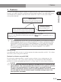
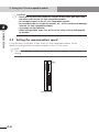
1. Features
1. Features
Master station
Station that controls entire CC-Link system.
The PLC master module corresponds to this.
Remote device station
Station controlled by master station in CC-Link
system. The robot controller corresponds to this.
Remote I/O station
Station controlled by master
station in CC-Link system.
CC-Link is a registered trademark of CC-Link partner association.
The CC-Link compatible module provided with a
label is compatible with CCLink Ver.1.10.
n
NOTE
The dedicated input of STD.DIO connector provided on the RCX240 controllers
will be disabled except for an interlock signal (DI 11). When the Board condition
(external 24V monitor control) of system parameters is set invalid, the interlock
signal (DI 11) will also be disabled. On the RCX22x, the dedicated input of STD.
DIO connector will be disabled, but the interlock signal (DI 11) in SAFETY
connector enabled.
[Wiring saving]
One dedicated cable (4-wire) is used to connect the robot controller and PLC. This allows
the entire system wiring to be reduced.
[Emulated serialization on parallel DIO]
By making the robot controller’s internal settings without using a robot program, the
various I/O devices, such as the sensors and relays mounted on the robot controller’s
parallel I/O can be controlled from the PLC as if they were CC-Link system I/O devices.
c
CAUTION
An emergency stop terminal for hardwire is provided in SAFETY connector on the
robot controller. In the case of the RCX240, when the CC-Link system is used while
STD. DIO is not used (external DC 24V power supply is not used), the Board
condition (external 24V monitor control) of system parameters must be set invalid.
If it is left valid, the STD. DIO interlock signal is enabled causing an error in the
robot operation commands.
1-1
Chapter
1
OUTLINE
CC-Link is the abbreviation of Control & Communication Link. The CC-Link system
connects the robot controller and dispersed input/output modules with dedicated cables,
and controls these modules from the master station PLC. The CC-Link system allows
wiring to be reduced.
2. Mechanism
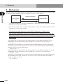
2. Mechanism
Chapter
1
The mechanism of communication is explained in this section to provide an understanding
of how the robot controller and PLC operate via the CC-Link system.
OUTLINE
ON/OFF information
Master station
PLC
Robot controller
:
@
q The robot controller’s ON/OFF information is sent to the master station PLC via the
network (CC-Link system cable).
w The master station PLC’s ON/OFF information is sent to the robot controller via the
network (CC-Link system cable).
* The robot controller monitors the ON/OFF information at a 10ms cycle.
* The ON/OFF information consists of 16 points each of dedicated I/O points, 96
points each of general-purpose I/O points as bit information, and two words each
of dedicated I/O words, 14 words each of general-purpose I/O words as word
information.
If the following is executed with the robot program in the robot controller, the bit
information will be sent to the master station PLC via the CC-Link system by q.
SO (20) = 1
Conversely, if the following is executed with the robot program, the bit information
received from the master station PLC via the CC-Link system will be monitored by w,
and will wait for the ON information.
WAIT SI (20) = 1
If the following is executed with the robot program in the robot controller, the word
information will be sent to the master station PLC via the CC-Link system by q.
SOW (2) = 256
Conversely, if the following is executed with the robot program, the word information
received from the master station PLC via the CC-Link system will be substituted in
integer variable A% by w.
A% = SIW (3)
1-2
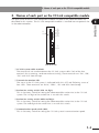
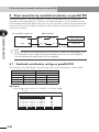
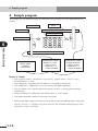
3. Names of each part on the CC-Link compatible module
3. Names of each part on the CC-Link compatible module
The part names of the CC-Link compatible module installed in the robot controller are
described in this section. The CC-Link compatible module is installed into an optional slot
in the robot controller.
9 1
4 5 7 6 8
@
9 1
4 5 2 3 ;
.
7 6 8
4 5 2 3 9 1
1
OUTLINE
=
2 3 Chapter
7 6 8
:
Front of the unit
q CC-Link system cable terminals
These terminals are used to connect the CC-Link system cable. Each of the four
terminals has a meaning, so do not make miswiring. These terminals are "DA", "DB",
"DG" and "SLD" from the top.
w Transmission monitor LED
The status in the CC-Link system is indicated with ON, OFF and flickering status of
four LEDs. These terminals are "RUN", "ERRL", "SD" and "RD" from the top.
e Station No. setting switch (LSB: 1st digit)
This is the rotary switch for setting the robot controller station No. in the CC-Link
system. The 1st digit of the station No. is set with this switch.
r Station No. setting switch (MSB: 2nd digit)
This is the rotary switch for setting the robot controller station No. in the CC-Link
system. The 2nd digit of the station No. is set with this switch.
t Communication speed switch (BPS)
This is the rotary switch for setting the CC-Link system’s communication speed.
1-3
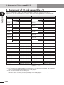
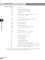
4. Assignment of CC-Link compatible I/O
4. Assignment of CC-Link compatible I/O
Chapter
1
The I/O expressions used in the robot controller’s program language and the I/O
expressions for the remote device stations differ. The correspondence is shown below.
Output from robot controller
OUTLINE
Program language
SOW(0) *3
SOW(1)
SOD(2)
SOD(4)
SOD(6)
SOD(8)
SOD(10)
SOD(12)
SOD(14)
SO0(7~0)
*1
SO1(7~0)
*1
*3
Input to robot controller
Remote device station
Program language
Remote device station
RWr0
SIW(0) *3
RWw0
RWr1
*3
RWw1
SOW(2)
RWr2
SOW(3)
RWr3
SOW(4)
RWr4
SOW(5)
RWr5
SOW(6)
RWr6
SOW(7)
RWr7
SOW(8)
RWr8
SOW(9)
RWr9
SOW(10)
RWrA
SOW(11)
RWrB
SOW(12)
RWrC
SOW(13)
RWrD
SOW(14)
RWrE
SOW(15)
RWrF
SIW(1)
SID(2)
SID(4)
SID(6)
SID(8)
SID(10)
SID(12)
SID(14)
RXn7~RXn0
SIW(2)
RWw2
SIW(3)
RWw3
SIW(4)
RWw4
SIW(5)
RWw5
SIW(6)
RWw6
SIW(7)
RWw7
SIW(8)
RWw8
SIW(9)
RWw9
SIW(10)
RWwA
SIW(11)
RWwB
SIW(12)
RWwC
SIW(13)
RWwD
SIW(14)
RWwE
SIW(15)
RWwF
SI0(7~0)
*1
RYn7~RYn0
*1
RYnF~RYn8
RXnF~RXn8
SI1(7~0)
SO2(7~0)
RX(n+1)7~RX(n+1)0
SI2(7~0)
RY(n+1)7~RY(n+1)0
SO3(7~0)
RX(n+1)F~RX(n+1)8
SI3(7~0)
RY(n+1)F~RY(n+1)8
SO4(7~0)
RX(n+2)7~RX(n+2)0
SI4(7~0)
RY(n+2)7~RY(n+2)0
SO5(7~0)
RX(n+2)F~RX(n+2)8
SI5(7~0)
RY(n+2)F~RY(n+2)8
SO6(7~0)
RX(n+3)7~RX(n+3)0
SI6(7~0)
RY(n+3)7~RY(n+3)0
SO7(7~0)
RX(n+3)F~RX(n+3)8
SI7(7~0)
RY(n+3)F~RY(n+3)8
SO10(7~0)
RX(n+4)7~RX(n+4)0
SI10(7~0)
RY(n+4)7~RY(n+4)0
SO11(7~0)
RX(n+4)F~RX(n+4)8
SI11(7~0)
RY(n+4)F~RY(n+4)8
SO12(7~0)
RX(n+5)7~RX(n+5)0
SI12(7~0)
RY(n+5)7~RY(n+5)0
SO13(7~0)
RX(n+5)F~RX(n+5)8
SI13(7~0)
RY(n+5)F~RY(n+5)8
SO14(7~0)
RX(n+6)7~RX(n+6)0
SI14(7~0)
RY(n+6)7~RY(n+6)0
SO15(7~0)
RX(n+6)F~RX(n+6)8
SI15(7~0)
RY(n+6)F~RY(n+6)8
------------
RX(n+7)F~RX(n+7)0 *2
------------
RY(n+7)F~RY(n+7)0 *2
n: Address assigned to master module with station No. setting
n= (station No. - 1) x 2
Caution)
*1: Has a meaning in the robot controller’s internal process as a dedicated input/output. This cannot be
used as a general-purpose input/output in the robot program.
*2: This area is reserved for the CC-Link system.
*3: Has a meaning in the robot controller’s internal process as a dedicated command region. This
cannot be used as a general-purpose input/output in the robot program.
1-4
4. Assignment of CC-Link compatible I/O
n
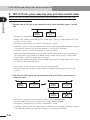
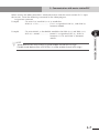
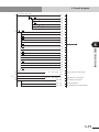
An example of the flow of the I/O information in the robot controller (remote device
station) is shown below. The buffer memory in the master station used to store the I/O
information differs according to the PLC type and station No, etc. Refer to the PLC manual
for details.
PLC CPU
(A1SHCPU)
X17F to X100
D115 to D100
Y17F to Y100
D135 to D120
FROM
TO
Master station
(A1SJ61BT11)
Remote input
Robot controller
E7h to E0h
2EFh to 2E0h
RX(n+7)F to RXn0
RWrF to RWr0
167h to 160h
1EFh to 1E0h
RY(n+7)F to RYn0
RWwF to RWw0
Remote input
Automatic update
1-5
Chapter
1
OUTLINE
NOTE
• SIW(n) and SOW(n) are handled as numerical data of word with no sign.
SID(n) and SOD(n) are handled as numerical data of double words with a sign.
• The dedicated input of STD.DIO connector provided on the RCX240 controllers
will be disabled except for an interlock signal (DI 11). When the Board condition
(external 24V monitor control) of system parameters is set invalid, the interlock
signal (DI 11) will also be disabled. On the RCX22x, the dedicated input of STD.
DIO connector will be disabled, but the interlock signal (DI 11) in SAFETY
connector enabled.
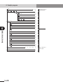
5. Shift of CC-Link system connection status and robot controller status
5. Shift of CC-Link system connection status and robot controller status
Chapter
1
Always start the CC-Link system specification robot controller in the servo OFF state
after the power is turned ON.
OUTLINE
q Normal state of CC-Link system connection when robot controller power is turned
ON
Robot
controller
Master station
PLC
• Emergency stop/interlock signals in CC-Link system are valid.
• When SAFE mode is enabled, service mode input signal is made valid with SI (02)
in the CC-Link system.
• Emergency stop terminal in SAFETY connector is valid.
• Interlock signal in STD. DIO connector is valid unless the Board condition (external
24V monitor control) of system parameters is set invalid. (RCX240)
• Interlock signal in SAFETY connector is valid. (RCX22x)
• When the Board condition (external 24V monitor control) of system parameters is
left valid while SAFE mode is enabled, service mode input signal is made valid
with DI (02) in SAFETY connector. (RCX240)
• When SAFE mode is enabled, service mode input signal is made valid with DI (02)
in SAFETY connector. (RCX22x)
* The signals in the CC-Link system are sent and received.
* Always initialize with the master station PLC when connecting to the CC-Link
system.
w Shift from CC-Link system normal connection state to CC-Link system erroneous
connection state
Robot
controller
Master station
PLC
Robot
controller
Master station
PLC
Robot
controller
Master station
PLC
or
• Emergency stop input turns off with SI (00) in the robot controller.
• Service mode input turns off with SI (02) in the robot controller.
• Emergency stop terminal in SAFETY connector is valid.
• Interlock signal in STD. DIO connector is valid unless the Board condition (external
24V monitor control) of system parameters is set invalid. (RCX240)
1-6
5. Shift of CC-Link system connection status and robot controller status
• Interlock signal in SAFETY connector is valid. (RCX22x)
• When the Board condition (external 24V monitor control) of system parameters is
left valid while SAFE mode is enabled, service mode input signal is made valid
with DI (02) in SAFETY connector. (RCX240)
* The signals in the CC-Link system are not sent or received.
* The "CC-Link Communication Error" is added to the error history in the robot
controller.
* If the connection to the CC-Link system shifts from the normal state to the
erroneous state, the CC-Link system connection must be returned to the normal
state.
* The CC-Link system will return when the CC-Link system connection is recovered
to the normal state.
e CC-Link system erroneous connection state due to following factors when robot
controller power is turned ON
• Connection to CC-Link system not possible
• Error in master station PLC
Robot
controller
Master station
PLC
Robot
controller
Master station
PLC
• Emergency stop/interlock signals in CC-Link system are invalid.
• When SAFE mode is enabled, service mode input signal is made valid with SI (02)
in the CC-Link system.
• Emergency stop terminal in SAFETY connector is valid.
• Interlock signal in STD. DIO connector is valid unless the Board condition (external
24V monitor control) of system parameters is set invalid. (RCX240)
• Interlock signal in SAFETY connector is valid. (RCX22x)
• When the Board condition (external 24V monitor control) of system parameters is
left valid while SAFE mode is enabled, service mode input signal is made valid
with DI (02) in SAFETY connector. (RCX240)
• When SAFE mode is enabled, service mode input signal is made valid with DI (02)
in SAFETY connector. (RCX22x)
* The signals on the CC-Link system cannot be exchanged.
* As opposed to the state given in w, in this state, the emergency stop state by SI (00)
is not attained in the controller, so the robot can be operated from the
programming box. (The robot controller can be started independently when setting
up the system, etc.)
1-7
1
OUTLINE
• When SAFE mode is enabled, service mode input signal is made valid with DI (02)
in SAFETY connector. (RCX22x)
Chapter
5. Shift of CC-Link system connection status and robot controller status
* Service mode input signal cannot be invalidated with SI (02) when SAFE mode is
enabled, so change the service mode parameter setting in SYSTEM > PARAM
mode. In this case, take full precautions to prevent improper settings that might
lead to a hazardous situation.
Chapter
1
OUTLINE
* When the connection to the CC-Link system is correctly recovered, the system will
automatically return to the CC-Link system.
* The "CC-Link Communication Error" has been added to the error history in the
robot controller.
(A standby state for up to 2.5 seconds will occur to check the communication.)
r Transmission from CC-Link system erroneous connection state to CC-Link correct
connection state when robot controller power is turned ON
Robot
controller
Master station
PLC
Robot
controller
Master station
PLC
Robot
controller
Master station
PLC
• CC-Link system emergency stop/interlock signals change to valid state.
• Emergency stop terminal in SAFETY connector is valid.
• Interlock signal in STD. DIO connector is valid unless the Board condition (external
24V monitor control) of system parameters is set invalid. (RCX240)
• Interlock signal in SAFETY connector is valid. (RCX22x)
• When the Board condition (external 24V monitor control) of system parameters is
left valid while SAFE mode is enabled, service mode input signal is made valid
with DI (02) in SAFETY connector. (RCX240)
• When SAFE mode is enabled, service mode input signal is made valid with DI (02)
in SAFETY connector. (RCX22x)
* The signals in the CC-Link system can be sent and received.
* When the connection to the CC-Link system shifts to the normal state, the
initialization process must be carried out with the master station PLC when
connecting to the CC-Link system.
* When service mode parameter setting in SYSTEM > PARAM mode has been
changed while SAFE mode is enabled, make the service mode parameter setting
again. In this case, take full precautions to prevent improper settings that might
lead to a hazardous situation.
* The CC-Link system will return when the CC-Link system connection is recovered
to the normal state.
1-8
Chapter 2
CONNECTION
Contents
1.
Confirming the CC-Link compatible module settings 2-1
2.
Setting to the CC-Link system specification controller 2-2
2.1
2.2
2.3
Saving the robot controller data
Installing the CC-Link compatible module
Response when starting the robot controller
3.
Setting the CC-Link compatible module
3.1
3.2
Setting the station No.
Setting the communication speed
4.
Noise measures
4.1
Mounting the ferrite core
5.
Connecting to the CC-Link system
5.1
5.2
Connecting to the cable terminal to the controller
Testing the line from the master station PLC
6.
Parameter setting for CC-Link serial I/O board 2-9
6.1
Parameter setting for CC-Link serial I/O board
2-2
2-2
2-2
2-3
2-3
2-4
2-6
2-6
2-7
2-7
2-8
2-10
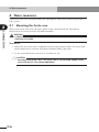
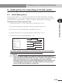
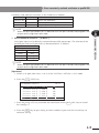
1. Confirming the CC-Link compatible module settings
1. Confirming the CC-Link compatible module settings
When using the CC-Link system specification robot controller, the CC-Link compatible
module's MAC ID and communication speed setting can be confirmed from a
programming box (RPB for RCX22x and RCX240 or MPB for RCX14x; hereafter called
"MPB/RPB").
Chapter
2
→ Follow the procedures given in section 2., and change the settings for the CCLink system specifications.
• For CC-Link system specification robot controller
(When robot controller is purchased with CC-Link compatible module mounted)
→ Follow the procedures given in section 3., and set the station No. and
communication speed.
Confirmation position
SYSTEM V8.29
Robot = YK250X
Axis = XYZR
Standard = SRAM/364kB,DIO_N
Opt−ifo = CCLnk(S1/10M)
PARAM CMU OPTION INIT DIAGNOS
[Operation]
1. Press the
MODE
2. Press the
F 4
key on the MPB/RPB.
(SYSTEM) key on the MPB/RPB.
3. The display above will appear. The station No. and communication speed set for the
CC-Link system will appear in the parentheses following "CCLnk" on the screen. The
meaning of the above example is shown below.
S1
: Station No. 1
(Setting range: 1 to 61)
* Four stations are occupied. Thus, this means that (station No. +3) is
occupied.
10M : 10Mbps
(Setting communication speed [unit: bps]: 156K, 625K, 2.5M, 5M, 10M)
* The communication speed must match the master station setting.
c
CAUTION
If the robot controller is not connected to the CC-Link system or if there is an
error in the CC-Link system, the error "CC-Link Communication Error" will
appear on the MPB/RPB when the robot controller power is turned ON. The
above settings can be confirmed even in this state.
2-1
CONNECTION
• When connecting CC-Link compatible module to existing robot controller
2. Setting to the CC-Link system specification controller
2. Setting to the CC-Link system specification controller
Chapter
When connecting the CC-Link compatible module to an existing robot controller, the
CC-Link compatible module must be installed in the robot controller. Check the CC-Link
system specifications with the procedure given in section 1.
2
2.1
CONNECTION
Before installing the CC-Link compatible module into the robot controller, be sure to save
the data stored in the robot controller into an external memory by using VIP software, etc.
2.2
Saving the robot controller data
Installing the CC-Link compatible module
Install the CC-Link compatible module into the robot controller. Also set the station No.
and communication baud rate for the CC-Link compatible module with the procedures
given in "3. Setting the CC-Link compatible module" in chapter 2.
2.3
Response when starting the robot controller
The robot controller will always start up with an "option board setting error" after the CCLink compatible module has been installed. Make the following settings as explained
below.
[Procedure]
1. Make connections to all input connectors on the front panel of the robot controller.
2. The following type of question will appear on the MPB/RPB screen, so answer as
"YES".
POWER ON
12.70:Incorrect option setting
change OptionSlot OK? YES NO
3. If the controller does not operate properly because of a memory error, etc., load the
data saved in step 2.1 into the controller. Refer to the controller user's manual for
details on loading the data. If the robot controller is not correctly connected with
the CC-Link system, the message "CC-Link Communication Error" will appear on the
MPB/RPB.
n
2-2
NOTE
For instructions on how to load data using the support software VIP, refer to the
VIP user's manual.
3. Setting the CC-Link compatible module
3. Setting the CC-Link compatible module
To connect the CC-Link system specification controller to the CC-Link system, the
station No. and communication speed must be set with the rotary switch on the CC-Link
compatible module. Confirm the current station No. and communication speed with the
procedures given in section 1.
Setting the station No.
Using the rotary switches MSB and LSB in front of the CC-Link compatible module, set the
station No. of the robot controller in the CC-Link system.
n
NOTE
Up to 64 stations can be set in the CC-Link system, but the CC-Link system itself
occupies 4 stations (specified No. +3), so set the station No. between 1 and 61.
9 1
4 5 2 3 7 6 8
9 1
4 5 2 3 MSB
LSB
7 6 8
9 1
4 5 2 3 7 6 8
Front of the unit
w
WARNING
WHEN SETTING THE STATION NO., COMPLETELY SHUT OFF THE POWER SUPPLIED TO
THE ROBOT CONTROLLER.
[Procedures]
1. Check the station No. of the robot controller in the CC-Link system.
The station No. must be set between 1 and 61.
2. Using a flat-blade precision screwdriver, set the 10th digit on rotary switch MSB.
3. In the same manner, set the 1st digit on rotary switch LSB.
2-3
2
CONNECTION
3.1
Chapter
3. Setting the CC-Link compatible module
c
Chapter
2
Setting the communication speed
Using the rotary switch BPS in front of the CC-Link compatible module, set the
communication speed for the robot controller in the CC-Link system.
n
NOTE
The communication speed must match the CC-Link system’s master station
setting.
BPS
9 1
4 5 2 3 7 6 8
9 1
4 5 2 3 7 6 8
9 1
4 5 2 3 7 6 8
CONNECTION
3.2
CAUTION
• Never directly touch the conductive sections or electronic parts other than
the rotary switch on the CC-Link compatible module.
• Do not apply impact on the CC-Link compatible module.
• Do not place water or conductive matters, etc., which could cause damage
near the CC-Link compatible module.
• Accurately set the station No.
• When setting the BPS, make sure not to set the rotary switches MSB and LSB
by mistake.
Front of the unit
2-4
3. Setting the CC-Link compatible module
w
WARNING
WHEN SETTING THE STATION NO., COMPLETELY SHUT OFF THE POWER SUPPLIED TO
THE ROBOT CONTROLLER.
[Procedures]
Chapter
Switch No.
0
1
2
3
4
Other than left setting
Communication speed [bps]
156K
625K
2.5M
5M
10M
Error
2. Using a flat-blade precision screwdriver, set the switch No. corresponding to the
communication speed with rotary switch BPS.
c
CAUTION
• Never directly touch the conductive sections or electronic parts other than
the rotary switch on the CC-Link compatible module.
• Do not apply impact on the CC-Link compatible module.
• Do not place water or conductive matters, etc., which could cause damage
near the CC-Link compatible module.
• Accurately set the communication speed.
• When setting the MSB and LSB, make sure not to set the rotary switch BPS by
mistake.
2-5
2
CONNECTION
1. Confirm the communication speed for the robot controller in the CC-Link system.
The communication speed must be set between 156K and 10Mbps. The
correspondence of the communication speed and switch is shown below.
4. Noise measures
4. Noise measures
Two ferrite cores must be mounted on the input power cable when connecting to the CCLink system.
Chapter
2
4.1
Mounting the ferrite core
CONNECTION
Mount two ferrite cores onto the input power cable connected to the input power
connector on the front panel of the robot controller.
w
WARNING
COMPLETELY SHUT OFF THE POWER SUPPLY TO THE INPUT POWER CABLE BEFORE
STARTING THIS WORK.
[Procedures]
1. Mount the two ferrite cores (supplied) onto the input power cable. The ferrite core
should be placed as close to the robot controller body as possible.
2. Fix the mounted ferrite core with an Insulock tie, etc.
c
2-6
CAUTION
Securely fix the ferrite core. If the ferrite core is not mounted, trouble could
occur with the CC-Link system operations.
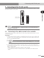
5. Connecting to the CC-Link system
5. Connecting to the CC-Link system
The CC-Link system cable must be connected to the CC-Link compatible module in order
to connect to the CC-Link system.
Chapter
2
9 1
4 5 2 3 7 6 8
9 1
CONNECTION
4 5 2 3 7 6 8
9 1
4 5 2 3 7 6 8
Cable terminal
DA
DB
DG
SLD
Front of the unit
w
5.1
WARNING
WHEN SETTING THE STATION NO., COMPLETELY SHUT OFF THE POWER SUPPLIED TO
THE ROBOT CONTROLLER.
Connecting to the cable terminal to the controller
Connect the CC-Link system cable to the CC-Link system cable terminal on the CC-Link
compatible module.
[Procedure]
1. Using a phillips head screwdriver, completely loosen the two screws on both sides
of the CC-Link system cable terminal, and remove the terminal block section from
the CC-Link compatible module.
c
CAUTION
Always remove the terminal block section when installing the CC-Link system
cable.
2. Using a phillips head screwdriver, securely fix the CC-Link system cable to the
terminal block removed in step 1. The name of each terminal on the cable terminal
block is shown above.
* When connecting a terminator, connect it across DA-DB.
* A slit to prevent incorrect inverted insertion is provided on the cable terminal
block.
2-7
5. Connecting to the CC-Link system
c
Chapter
2
CONNECTION
CAUTION
• Securely fix the CC-Link system cable.
• Carefully carry out the work to avoid applying excessive force on the CCLink cable.
• Treat each end of the CC-Link system cable wire with a round terminal or Y
terminal so that it will not dislocate.
• Carefully carry out the work so that the CC-Link system cable is not
incorrectly wired.
3. Connect the cable terminal, into which the CC-Link system cable has been installed,
to the CC-Link compatible module terminal block section on the robot controller,
and completely fix with the two screws on both sides using a Phillips head
screwdriver.
c
5.2
CAUTION
Refer to the master station PLC instruction manual for details on the CC-Link
system cable connection.
Testing the line from the master station PLC
The master station PLC in the CC-Link system has a function to test the line to the remote
station. Using this function, confirm that the robot controller is accurately recognized as
a remote station in the CC-Link system. Refer to the master station PLC instruction manual
for details.
c
2-8
CAUTION
If the line test results indicate a correct connection, place the CC-Link system
cable into a conduit, or fix it with a clamp.
6. Parameter setting for CC-Link serial I/O board
6. Parameter setting for CC-Link serial I/O board
The following functions are enabled or disabled by setting the parameters for the CC-Link
serial I/O board.
Parameter
1
3
Chapter
Enables or disables the serial I/O board. When set to "VALID" the
serial I/O can be used. When set to "INVALID" the serial I/O cannot
be used.
Remote cmd / IO cmd
(SI05)
Enables or disables the functions of remote commands and I/O
commands using word information and bit information. When set to
"VALID" the remote commands and I/O commands can be used.
When set to "INVALID" the remote commands and I/O commands
cannot be used.
This parameter cannot be set to "VALID" simultaneously with
parameter 3.
Output MSG to SOW(1)
Enables or disables the function to send an message number, which
is displayed on the MPB/RPB, to word information SOW(1). When set
to "VALID" the message number to be displayed on the MPB/RPB
will be output. When set to "INVALID" the message number to be
displayed on the MPB/RPB will not be output. This parameter cannot
be set to "VALID" simultaneously with parameter 2.
n
NOTE
• When not using the serial I/O board, set the "board condition" ("serial I/O" for
RCX22x) parameter to "INVALID".
• When the "board condition" ("serial I/O" for RCX22x) parameter is set to
"INVALID", the dedicated input/output of STD.DIO connector becomes enabled.
When the "board condition" parameter is set to "VALID", the dedicated input
(except DI11 for RCX240) of STD.DIO connector becomes disabled.
• For remote commands and I/O commands, refer to the command reference
manual.
• For a description of codes issued from the message output function for SOW(1),
refer to "1. Error message" in chapter 9.
• When the Remote command & I/O command parameter is set to "VALID", the
Output MSG to SOW(1) parameter cannot be set to "VALID".
Likewise, when the Output MSG to SOW(1) parameter is set to "VALID", the
Remote command & I/O command parameter cannot be set to "VALID".
2-9
2
CONNECTION
2
[RCX240]
Board condition
[RCX22x]
Serial I/O
Meaning
6. Parameter setting for CC-Link serial I/O board
6.1
Parameter setting for CC-Link serial I/O board
[Operation]
1. Press the
F 1
(PARAM) key in "SYSTEM" mode to enter "SYSTEM>PARAM" mode.
Chapter
2
CONNECTION
2. Press the F 5 (OP. BRD) key in "SYSTEM>PARAM" mode to enter the option board
parameter setting mode.
The option boards installed in the controller are displayed in order on the MPB
screen.
SYSTEM>PARAM>OP.BRD V8.18
1.DIO_N(1) VALID
2.. −−−
3.CCLnk(S1/10M) VALID
4. −−−
SELECT
Option boards installed into the option slots are displayed on the MPB screen.
Type
Display
Meaning
DIO_N(n)
An option DIO board of NPN specifications is installed. The
number in parentheses is an ID number.
DIO_P(n)
An option DIO board of PNP specifications is installed. The
number in parentheses is an ID number.
CCLnk(n/m)
A CC-Link unit is installed. Letters in parentheses indicate a
station number "n" and a communication speed "m".
D_Net(n/m)
A DeviceNet unit is installed. Letters in parentheses indicate a
MAC ID number "n" and communication speed "m".
Profi(n/m)
A Profibus unit is installed. Letters in parentheses indicate a
station address "n" and communication speed "m".
Network
E_Net
An Ethernet unit is installed.
YC-Link
YCLnk(Mn)
A YC-Link unit is installed. Letters in parentheses indicate a
station number "n".
Option DIO
Serial I/O
3. In "SYSTEM>PARAM>OP. BRD" mode, select the "CCLnk" with the cursor (↑/↓) keys
and press the F 1 (SELECT) key.
SYSTEM>PARAM>OP.BRD>SELECT V8.18
1.board condition VALID
2.remote cmd / IO cmd(SI05) VALID
3.Output MSG to SOW(1) INVALID
EDIT JUMP
2-10
6. Parameter setting for CC-Link serial I/O board
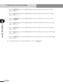
4. Select the parameter with the cursor (↑/↓) keys.
SYSTEM>PARAM>OP.BRD>SELECT V8.18
1.board condition VALID
2.remote cmd / IO cmd(SI05) VALID
3.Output MSG to SOW(1) INVALID
Chapter
2
CONNECTION
EDIT JUMP
5. Press the
F 1
(EDIT) key.
SYSTEM>PARAM>OP.BRD>SELECT V8.18
1.board condition VALID
2.remote cmd / IO cmd(SI05) VALID
3.Output MSG to SOW(1) INVALID
INVALID VALID
6. Press the
F 1
(INVALID) or
F 2
(VALID) key.
7. Press the ESC key to quit the edit mode. To continue setting another parameter,
use the cursor (↑/↓) keys to select the parameter.
2-11
MEMO
2-12
Chapter 3
COMMUNICATION
Contents
1.
State when robot controller power is turned ON 3-1
2.
Initial process for connecting to CC-Link system
2.1
Initial data process
3.
Communication with master station PLC
3.1
3.2
Receiving data
Transmitting data
4.
Direct connection by emulated serialization on parallel DIO 3-8
4.1
Emulated serialization setting on parallel DIO
5.
Referring to communication data
5.1
Referring to the data from the programming box
3-3
3-3
3-4
3-4
3-6
3-8
3-11
3-11
1. State when robot controller power is turned ON
1. State when robot controller power is turned ON
The CC-Link system specification robot controller always starts operation in servo OFF
state when the power turned ON.
q When connection to CC-Link system is correctly established.
The following conditions must be satisfied to correctly connect to the CC-Link
system:
• The CC-Link system cable must be physically connected
• The station No. and communication speed must be correctly set
• The master station PLC must be operating correctly
Chapter
3
w When connection to CC-Link system is incorrectly established
The following causes can be considered a correct connection with the CC-Link
system cannot be established:
• The CC-Link system cable is not physically connected
• The station No. or communication speed is set incorrectly
• The master station PLC is not operating correctly
When the robot controller is incorrectly connected to the CC-Link system, the error
state will be indicated with the LEDs on the CC-Link compatible module. Note that if
the master station PLC is not operating correctly, nothing will appear on the LEDs.
The emergency stop signal and interlock signal in the CC-Link system are invalid in
this case, so the robot controller can be operated independently. However, if the
correct state has been established even once after the robot controller power was
turned ON, the robot controller’s emergency stop state cannot be canceled without
correctly connecting to the CC-Link system.
The emergency stop terminal in SAFETY connector is always kept valid. On the
RCX22x, the interlock signal in SAFETY connector is also valid. On the RCX240, the
interlock signal in STD. DIO connector is valid unless the Board condition (external
24V monitor control) of system parameters is set invalid.
When SAFE mode is enabled, service mode input signal to the RCX22x is made valid
with DI (02) in SAFETY connector. On the RCX240, service mode input signal is
made valid with DI (02) in SAFETY connector unless the Board condition (external
24V monitor control) of system parameters is set invalid.
3-1
COMMUNICATION
When the robot controller is correctly connected to the CC-Link system, the normal
state will be indicated with the LEDs on the CC-Link compatible module.
At this time, the emergency stop signal and interlock signal in the CC-Link system
will be valid, so these signals must be turned ON with the initial data process.
The emergency stop terminal in SAFETY connector is always kept valid. On the
RCX22x, the interlock signal in SAFETY connector is also valid. On the RCX240, the
interlock signal in STD. DIO connector is valid unless the Board condition (external
24V monitor control) of system parameters is set invalid.
When SAFE mode is enabled, service mode input signal is made valid with SI (02) in
the CC-Link system. Service mode input signal to the RCX22x is also made valid with
DI (02) in SAFETY connector. On the RCX240, service mode input signal is made
valid with DI (02) in SAFETY connector unless the Board condition (external 24V
monitor control) of system parameters is set invalid.
1. State when robot controller power is turned ON
Service mode input signal in the CC-Link system cannot be invalidated when SAFE
mode is enabled, so change the service mode setting in SYSTEM > PARAM mode.
In this case, take full precautions to prevent improper settings that might lead to a
hazardous situation.
* For meanings of LED display, see Chapter 4 in this manual.
Chapter
3
COMMUNICATION
3-2
2. Initial process for connecting to CC-Link system
2. Initial process for connecting to CC-Link system
The initial data process must be carried out to correctly connect to the CC-Link system.
2.1
Initial data process
The initial data process is carried out to confirm that the robot controller is correctly
connected to the CC-Link system. Prepare the process on the master station PLC side so
that the following type of process is always carried out before data is exchanged.
Initial data process (master station PLC side)
w Turn RYn0 (emergency stop input) and RYn9 (interlock input) ON.
e Turn RY(n+7)8 (initial data process completion flag) ON.
r Confirm that RX(n+7)8 (initial data process request flag) is OFF.
t Confirm that RX(n+7)B (remote Ready) is ON.
RX (n+7) 8
on
off
RX (n+7) B
on
off
RYn0
on
off
RYn9
on
off
RY (n+7) 8
on
off
The robot controller internal process will automatically start when the power is
turned ON and the system is returned from an error state.
c
3
COMMUNICATION
q Confirm that RX(n+7)8 (initial data process request flag) is ON.
Chapter
CAUTION
• RX(n+7) B (remote Ready) must always be used on the master station PLC
side as the flag to indicate whether the robot controller is operating correctly.
• When starting up the system in the emergency stop state using RYn0
(emergency stop input), carry out the initial data process first, and then turn
RYn0 (emergency stop input) OFF. The robot controller will start up in the
servo OFF state when the power is turned ON.
3-3
3. Communication with master station PLC
3. Communication with master station PLC
The method for communicating with the master station PLC by using the robot program
when the CC-Link system is correctly connected is explained in this section.
3.1
Chapter
3
Receiving data
Data is received by reading the master station PLC output device data with the robot
controller’s input port. The correspondence of the master station PLC’s output device
numbers and robot controller’s input port numbers is shown below.
COMMUNICATION
Master station
output device No.
Robot controller
input port No.
Master station
output device No.
Robot controller
input port No.
RYn7~RYn0
SI(07)~SI(00)
RWwn
SIW(0)
RYnF~RYn8
SI(17)~SI(10)
RWw(n+1)
SIW(1)
RY(n+1)7~RY(n+1)0
SI(27)~SI(20)
RWw(n+2)
RY(n+1)F~RY(n+1)8
SI(37)~SI(30)
RWw(n+3)
RY(n+2)7~RY(n+2)0
SI(47)~SI(40)
RWw(n+4)
RY(n+2)F~RY(n+2)8
SI(57)~SI(50)
RWw(n+5)
RY(n+3)7~RY(n+3)0
SI(67)~SI(60)
RWw(n+6)
RY(n+3)F~RY(n+3)8
SI(77)~SI(70)
RWw(n+7)
RY(n+4)7~RY(n+4)0
SI(107)~SI(100)
RWw(n+8)
RY(n+4)F~RY(n+4)8
SI(117)~SI(110)
RWw(n+9)
RY(n+5)7~RY(n+5)0
SI(127)~SI(120)
RWw(n+10)
RY(n+5)F~RY(n+5)8
SI(137)~SI(130)
RWw(n+11)
RY(n+6)7~RY(n+6)0
SI(147)~SI(140)
RWw(n+12)
RY(n+6)F~RY(n+6)8
SI(157)~SI(150)
RWw(n+13)
SID(2)
SID(4)
SID(6)
SID(8)
SID(10)
SID(12)
RWw(n+14)
SIW(2)
SIW(3)
SIW(4)
SIW(5)
SIW(6)
SIW(7)
SIW(8)
SIW(9)
SIW(10)
SIW(11)
SIW(12)
SIW(13)
SIW(14)
SID(14)
RWw(n+15)
SIW(15)
n: Address assigned to master module with station No. setting
c
3-4
CAUTION
SIW(0) and SIW(1) are viewed as dedicated input ports. The robot controller
handles these ports as input ports of meaningful data, so do not use them as
general-purpose input ports.
Set these ports to "0" in most cases.
3. Communication with master station PLC
When reading the bit information from the master station PLC’s output device No. with
the robot controller, write the following commands in the robot program in the same
manner as the DI input port:
WAIT command
Assignment statement
Example
:To wait for RY(n+1)0 to turn ON
WAIT SI(20) = 1 ................. * The robot program will wait for SI(20) to turn
ON.
:To read the RY(n+1) 0 to RY(n+1)7 data in variable A
A = SI2() ............................ * The SI2() data will be converted into a
decimal and assigned to variable A.
If SI2() is 7Fh, variable A will be 127.
n
NOTE
The SI statement in the robot language can be defined from SI0 ( ) to SI27 ( ), but
the CC-Link compatible module accepts from SI0 ( ) to SI15 ( ).
When reading the word information from the master station PLC’s output device No. with
the robot controller, write the following command in the robot program.
Assignment statement
Example
:To read the RWw (n+2) word data in variable B
B = SIW (2) ........................ * The SIW (2) data will be assigned to variable
B as a decimal. If SIW (2) is 01FFh, variable B
will be 511.
Example
:To read the RWw (n+2) and RWw (n+3) double word data into variable C
C = SID (2) ........................ * The SIW (2) and SIW (3) data will be assigned
to variable C as a decimal.
If SIW (2) is 0010h and SIW (3) is 0001h,
variable C will be 65552.
n
NOTE
Word data read out with SIW(n) is a little endian format with no sign.
Double word data read out with SID(n) is a little endian format with a sign.
3-5
3
COMMUNICATION
Example
Chapter
3. Communication with master station PLC
3.2
Transmitting data
Data is transmitted by writing the robot controller output port data into the master station
PLC’s input device. The correspondence of the master station PLC’s input device numbers
and robot controller’s output port numbers is shown below.
Master station
input device No.
Robot controller
output port No.
Master station
input device No.
Robot controller
output port No.
RXn7~RXn0
SO(07)~SO(00)
RWrn
SOW(0)
3
RXnF~RXn8
SO(17)~SO(10)
RWr(n+1)
SOW(1)
RX(n+1)7~RX(n+1)0
SO(27)~SO(20)
RWr(n+2)
RX(n+1)F~RX(n+1)8
SO(37)~SO(30)
RWr(n+3)
RX(n+2)7~RX(n+2)0
SO(47)~SO(40)
RWr(n+4)
RX(n+2)F~RX(n+2)8
SO(57)~SO(50)
RWr(n+5)
RX(n+3)7~RX(n+3)0
SO(67)~SO(60)
RWr(n+6)
RX(n+3)F~RX(n+3)8
SO(77)~SO(70)
RWr(n+7)
RX(n+4)7~RX(n+4)0
SO(107)~SO(100)
RWr(n+8)
RX(n+4)F~RX(n+4)8
SO(117)~SO(110)
RWr(n+9)
RX(n+5)7~RX(n+5)0
SO(127)~SO(120)
RWr(n+10)
RX(n+5)F~RX(n+5)8
SO(137)~SO(130)
RWr(n+11)
RX(n+6)7~RX(n+6)0
SO(147)~SO(140)
RWr(n+12)
RX(n+6)F~RX(n+6)8
SO(157)~SO(150)
RWr(n+13)
COMMUNICATION
Chapter
SOD(2)
SOD(4)
SOD(6)
SOD(8)
SOD(10)
SOD(12)
RWr(n+14)
SOW(2)
SOW(3)
SOW(4)
SOW(5)
SOW(6)
SOW(7)
SOW(8)
SOW(9)
SOW(10)
SOW(11)
SOW(12)
SOW(13)
SOW(14)
SOD(14)
RWr(n+15)
SOW(15)
n: Address assigned to master module with station No. setting
c
CAUTION
SIW(0) and SIW(1) are viewed as dedicated input ports.
To write the robot controller’s bit information into the master station PLC’s input device
No., write the following commands in the robot program in the same manner as the DO
output port:
SET/RESET command
Assignment statement
OUT command
Example
: To turn RX(n+1)0 ON
SET SO(20) or SO(20) =1 .... * SO(20) will turn ON.
Example
: To write variable A data into RX(n+1)0 to RX(n+1)7
SO2() = A .......................... * The variable A data will be converted into a
binary and assigned to SO2().
If variable A is 127, 7Fh will be set in SO2().
n
3-6
NOTE
The SO statement in the robot language can be defined from SO2 ( ) to SO27 ( ),
but the CC-Link compatible module accepts from SO2 ( ) to SO15 ( ).
3. Communication with master station PLC
When writing the robot controller’s word information into the master station PLC’s input
device No., write the following command in the robot program.
Assignment statement
Example
: To write 512 into RWr (n+2) as word data
SOW (2) = 512 ................... * 512 is assigned to SOW (2), and SOW (2)
becomes 0200h.
Example
Chapter
: To write 69905 as the double word data for RWr (n+2) and RWr (n+3)
3
n
COMMUNICATION
SOD (2) = 69905................ * 69905 is assigned to SOD (2), SOW (2)
becomes 1111h and SOW (3) becomes
0001h.
NOTE
Word data written with SOW(n) is a little endian format with no sign.
Double word data written with SOD(n) is a little endian format with a sign.
3-7
4. Direct connection by emulated serialization on parallel DIO
4. Direct connection by emulated serialization on parallel DIO
The robot controller's parallel input data can be transferred to the serial output data
regardless of the robot program. Likewise, the robot controller's serial input data can be
transferred to the parallel output data. By using this function, a sensor or relay connected
to the parallel I/O of the robot controller can be used like a device connected to the CCLink master module.
Chapter
3
CC-Link Master station PLC
Robot controller
COMMUNICATION
Output
SI DO
Input
SO DI
CC-Link connection
n
4.1
Relay, valve, etc.
Sensor, etc.
Parallel I/O connection
NOTE
When the directly connected and set output port is used with the program, the
bit information may not become the intended value. Do not use the directly
connected and set output port with the program.
Emulated serialization setting on parallel DIO
The relation of the parallel port and serial port that can be connected is shown below.
Input device such as sensor
DI port →SO port
Output device such as valve
DO port ←SI port
DI2()
SO2()
DO2()
SI2()
DI3()
SO3()
DO3()
SI3()
DI4()
SO4()
DO4()
SI4()
DI5()
SO5()
DO5()
SI5()
[Operation]
1. Press the
F 3
(SIO) key in "SYSTEM > OPTION" mode.
SYSTEM>OPTION>SIO V8.01
1.Direct SI2() −> DO2() NO 2.Direct SI3() −> DO3() NO 3.Direct SI4() −> DO4() NO 4.Direct SI5() −> DO5() NO 5.Direct SO2() <− DI2() NO EDIT JUMP 3-8
4. Direct connection by emulated serialization on parallel DIO
Valid keys and submenu functions in this mode are as follows.
Valid keys
Menu
Cursor (↑/↓) keys
n
Function
Selects SIO parameters.
F1
EDIT
Sets SIO parameters.
F2
JUMP
Jumps to specified SIO parameter.
NOTE
When the port specified by SIO is identical with the port used by the program, the
output results might be inaccurate.
Serial port input can be directly connected to parallel port output. The relation of the
parallel port and serial port that can be connected is as follows.
Output device such as valve
DO port ←SI port
n
DO2()
SI2()
DO3()
SI3()
DO4()
SI4()
DO5()
SI5()
NOTE
When the port specified by SIO is identical with the port used by the program, the
output results might be inaccurate.
[Operation]
1. Select an SI port (from items 1 to 4) in the "SYSTEM > OPTION > SIO" mode.
2. Press the
F 1
(EDIT) key.
SYSTEM>OPTION>SIO V8.01
1.Direct SI2() −> DO2() NO 2.Direct SI3() −> DO3() NO 3.Direct SI4() −> DO4() NO 4.Direct SI5() −> DO5() NO 5.Direct SO2() <− DI2() NO SET NO 3. Press the F
the setting.
1
(SET) key to enable the connection or the
F 2
(NO) key to cancel
4. Press the ESC key to quit setting or select another SI port with the cursor keys to
continue setting.
3-9
3
COMMUNICATION
1. Direct connection from SI n ( ) to DO n ( )
Chapter
5. Referring to communication data
2. Direct connection from DI n ( ) to SO n ( )
Parallel port input can be directly connected to serial port output. The relation of the
parallel port and serial port that can be connected is as follows.
Input device such as sensor
DI port →SO port
Chapter
3
COMMUNICATION
n
DI2()
SO2()
DI3()
SO3()
DI4()
SO4()
DI5()
SO5()
NOTE
When the port specified by SIO is identical with the port used by the program, the
output results might be inaccurate.
[Operation]
1. Select a DI port (from items 5 to 8) in the "SYSTEM > OPTION > SIO" mode.
2. Press the
F 1
(EDIT) key.
SYSTEM>OPTION>SIO V8.01
4.Direct SI5() −> DO5() NO 5.Direct SI5() <− DI2() NO 6.Direct SO3() <− DI3() NO 7.Direct SO4() <− DI4() NO 8.Direct SO5() <− DI5() NO SET NO
3. Press the F
the setting.
1
(SET) key to enable the connection or the
F 2
(NO) key to cancel
4. Press the ESC key to quit setting or select another DI port with the cursor keys to
continue setting.
3-10
5. Referring to communication data
5. Referring to communication data
The ON/OFF information exchanged with the master station PLC can be referred to using
the programming box (RPB for RCX22x and RCX240 or MPB for RCX14x; hereafter called
"MPB/RPB"). Note that the MPB/RPB display update interval is longer than the CC-Link
data update interval, so if the ON/OFF interval is short, accurate information may not be
displayed.
5.1
Chapter
Referring to the data from the programming box
SYSTEM V8.01
SI monitor
SI0()=&B00000111 SI4()=&B11000000
SI1()=&B00001111 SI5()=&B00101000
SI2()=&B00010001 SI6()=&B00000111
SI3()=&B00000100 SI7()=&B00000000
PARAM CMU OPTION INIT DIAGNOS
* &Bxxxxxxx corresponds to the 0th bit to 7th bit from right to left.
SYSTEM V8.01
SIW monitor
SIW(0)=&H0132 SIW(4)=&H0000
SIW(1)=&H0001 SIW(5)=&H0000
SIW(2)=&H8000 SIW(6)=&HFFFF
SIW(3)=&H0000 SIW(7)=&H0000
PARAM CMU OPTION INIT DIAGNOS
* &Hxxxx expresses a hexadecimal.
[Operation]
1. Press the
DISPLAY
key on the MPB/RPB. A screen like that shown below will appear.
SYSTEM V8.01
DI monitor
DI0()=&B00000111 DI4()=&B11000000
DI1()=&B00001111 DI5()=&B00101000
DI2()=&B00010001 DI6()=&B00000111
DI3()=&B00000100 DI7()=&B00000000
PARAM CMU OPTION INIT DIAGNOS
2. Press the DISPLAY key on the MPB/RPB several times to check the status of SI input
ports 0 to 7.
3-11
3
COMMUNICATION
The data exchanged with the master station PLC can be referred to with the MPB/RPB. The
reference unit is the robot controller input/output port No.
5. Referring to communication data
3. Press the DISPLAY key on the MPB/RPB once more to check the status of SI input
ports 10 to 15.
4. Press the DISPLAY key on the MPB/RPB twice more to check the status of SO input
ports 0 to 7.
Chapter
3
5. Press the DISPLAY key on the MPB/RPB once more to check the status of SO input
ports 10 to 15.
COMMUNICATION
6. Press the DISPLAY key on the MPB/RPB twice more to check the status of SIW input
ports 0 to 7.
7. Press the DISPLAY key on the MPB/RPB once more to check the status of SIW input
ports 8 to 15.
8. Press the DISPLAY key on the MPB/RPB once more to check the status of SOW output
ports 0 to 7.
9. Press the DISPLAY key on the MPB/RPB once more to check the status of SOW output
ports 8 to 15.
10. To stop checking the input/output ports, press the
3-12
ESC
key.
Chapter 4
TROUBLESHOOTING
Contents
1.
Items to confirm before starting up CC-Link system
4-1
2.
Meanings of LEDs on CC-Link compatible module 4-2
3.
Troubleshooting
3.1
3.2
3.3
3.4
Robot controller front panel LED confirmation
Programming box error display confirmation
CC-Link compatible module LED confirmation
Confirmation from master station PLC
4.
Error messages relating to CC-Link
4-3
4-3
4-4
4-5
4-6
4-7
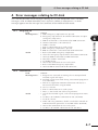
1. Items to confirm before starting up CC-Link system
1. Items to confirm before starting up CC-Link system
Confirm the following items before starting up the CC-Link system.
Confirmation details
Is the CC-Link compatible module accurately connected?
(Refer to Chapter 2 section 2 or 3.)
2
Is the robot controller set to the CC-Link system specifications?
(Refer to Chapter 2 section 1.)
3
Are the CC-Link compatible module station No. and communication speed correctly set?
(Refer to Chapter 2 section 1.)
4
Is the ferrite core connected to the power input cable to the robot controller?(Refer to
Chapter 2 section 4.)
5
Is the CC-Link system cable accurately connected to the CC-Link compatible module?
(Refer to Chapter 2 section 5.)
6
Was the line test from the master station PLC correct?
(Refer to the master station PLC instruction manual.)
7
Is the master station PLC set for the 4-station occupying remote device?
(Refer to the master station PLC instruction manual.)
8
Is the master station PLC exchanging the data for four stations? (The data for four
stations must always be exchanged.)
9
Has the initial data process been carried out between the master station and robot
controller? (Refer the initialization process in Chapter 3 section 2.)
10
Is the master station PLC judging that the robot controller is correctly functioning using
RX(n+7)8 (remote Ready)? (Refer the samples in Chapter 5 section 4.)
n
Chapter
4
NOTE
The dedicated input of STD.DIO connector provided on the RCX240 controllers
will be disabled except for an interlock signal (DI 11). When the Board condition
(external 24V monitor control) of system parameters is set invalid, the interlock
signal (DI 11) will also be disabled. On the RCX22x, the dedicated input of STD.
DIO connector will be disabled, but the interlock signal (DI 11) in SAFETY
connector enabled.
4-1
TROUBLESHOOTING
1
Check
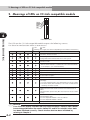
2. Meanings of LEDs on CC-Link compatible module
2. Meanings of LEDs on CC-Link compatible module
9 1
4 5 2 3 7 6 8
9 1
4 5 2 3 RUN
ERRL
SD
RD
7 6 8
9 1
4 5 2 3 7 6 8
Chapter
4
TROUBLESHOOTING
Front of the unit
The LEDs on the CC-Link compatible module express the following statuses.
Use these for confirmation when an error occurs.
: ON
: OFF
: Blinking (This might seem to be lit depending on the ambient environment.)
RUN
ERRL
SD
RD
Meaning
Normal communication is taking place, but the CRC error occurs
sometimes because of noise.
The settings have varied from the baud rate and station No.
setting made when connected to the CC-Link system.
(0.4s)
A CRC error occurred in the received data, and a response
cannot be made.
Normal communication
* Normal communication is established even if data initialization
is not complete. (See CAUTION below.)
There is no data addressed to the local station.
Specified station No. is not within the setting range.
Specified communication speed is not within the setting range.
Polling response is being carried out, but a CRC error occurred
in the refresh reception.
A CRC error occurred in the data addressed to the local station.
There is a problem with the master station
(Example)
1. CC-Link communication is not controlled by the master station.
2. The local station (RCX controller) is not set to a remote device
station by the master station.
There is no data addressed to the local station or the data
addressed to the local station cannot be received because of
noise.
Communication speed setting does not match the master station
setting.
Data cannot be received due to open-circuit fault, etc. in the
communication cable.
CC-Link compatible module is not set enabled.
CC-Link compatible module is broken.
Others
c
4-2
An improbable state
CAUTION
Even if the LED display indicates that the communication is normal, data cannot
be exchanged between the master station PLC and RCX controller unless data
has been initialized correctly. Check whether data has been initialized by
referring to Chapter 3.
3. Troubleshooting
3. Troubleshooting
If trouble occurs in the connection with the robot controller while starting up the CC-Link
system or during operation, check the following items in listed order.
3-1 Robot controller front panel LED confirmation
3-2 Programming box error display confirmation
3-3 CC-Link compatible module LED confirmation
Chapter
3-4 Confirmation from master station PLC
4
Robot controller front panel LED confirmation
[Confirmation item 1]
<Confirmation details>
• The "PWR" LED is OFF. (RCX240)
• The "RDY" LED is OFF. (RCX22x)
<Cause>
• Power is not being supplied to the robot controller.
<Countermeasures>
• Measure the voltage at the AC power input terminal of the power connector with a
multimeter and check that the rated voltage is being supplied.
* Refer to the robot controller user’s manual for the rated voltage for the robot
controller.
[Confirmation item 2]
<Confirmation details>
• The "ERR" LED is ON.
<Cause>
• The robot controller is in emergency stop.
• A major error has occurred in the robot controller.
<Countermeasures>
• Confirm the error message displayed on the programming box.
• Take measures by following the troubleshooting section in the robot controller user's
manual.
* Refer to the robot controller user's manual for details on the errors.
4-3
TROUBLESHOOTING
3.1
3. Troubleshooting
3.2
Programming box error display confirmation
[Confirmation item 1]
<Confirmation details>
• "CC-Link Communication Error" is displayed on the programming box.
<Cause>
• An error has occurred in the CC-Link system connection.
Chapter
<Countermeasures>
• Check whether the CC-Link system cable is disconnected or incorrectly connected.
4
• Check the station No. and communication speed settings for the CC-Link compatible
module.
TROUBLESHOOTING
• Confirm that the master station PLC is operating.
[Confirmation item 2]
<Confirmation details>
• Check whether an error other than "CC-Link Communication Error" is displayed on
the programming box. In this case, this problem is not related to the CC-Link system
connection. Note, however, the message "CC-Link Communication Error" may not
appear on the programming box if multiple errors have occurred simultaneously.
<Cause>
• An error has occurred in the robot controller.
<Countermeasures>
• Check the error message displayed on the programming box.
• Check the error history using the programming box. Check the error history in the
"SYSTEM > DIAGNOS > HISTORY" mode using the programming box.
• Take measures by following the troubleshooting section in the robot controller user's
manual.
* Refer to the robot controller user's manual for details on the errors.
4-4
3. Troubleshooting
3.3
CC-Link compatible module LED confirmation
[Confirmation item 1]
<Confirmation details>
• The LED display on the CC-Link compatible module is not "RUN. ERR. SD. RD" = "
".( :ON, :OFF)
<Cause>
• An error has occurred in the CC-Link system connection. Refer to table in Chapter 4
section 2 for the meanings of the LED displays.
• Check whether the CC-Link system cable is laid near the main circuit or power cable,
or whether it is bundled with these.
• Check that the ferrite core is connected to the robot controller’s power supply cable.
• Check the station No. and communication speed settings for the CC-Link compatible
module.
• Check that the master station PLC is operating correctly.
• Check that the robot controller on the master station PLC is set to the remote device
station.
[Confirmation item 2]
<Confirmation details>
• The LED display on the CC-Link compatible module is "RUN, ERR, SD, RD" = "
".( :ON, :OFF)
<Cause>
• The initial data process has not been executed when the CC-Link system was
connected. Refer to Chapter 3.
• The RX(n+7)B (remote Ready) signal is not ON.
<Countermeasures>
• Carry out the initial data process when connecting to the CC-Link system.
4-5
Chapter
4
TROUBLESHOOTING
<Countermeasures>
• Check whether the CC-Link system cable is disconnected or incorrectly connected,
and whether the terminator is connected.
3. Troubleshooting
3.4
Confirmation from master station PLC
[Confirmation item 1]
<Confirmation details>
• Using the master station PLC’s line test function, confirm robot controller is correctly
connected to the CC-Link system.
* Refer to the master station PLC instruction manual for details on the line test.
Chapter
4
[Confirmation item 2]
TROUBLESHOOTING
<Confirmation details>
• Using the master station PLC’s line test function, check whether an error has occurred
in the robot controller’s CC-Link connection.
<Cause>
• The ferrite core for noise measures is not connected.
• The CC-Link cable is laid near sources of noise such as the power cable.
<Countermeasures>
• Connect the ferrite core for noise measures onto the input power cable.
• Wire the CC-Link cable away from noise sources such as the power cable.
4-6
4. Error messages relating to CC-Link
4. Error messages relating to CC-Link
This section describes error messages relating to CC-Link compatible units. For other
messages, refer to robot controller user's manuals. When an error occurs, an error
message appears on the message line (2nd line) of the MPB or RPB screen.
12.1 : Emg.stop on
12.2 : Interlock on
Code
: &H0C02
Meaning/Cause : a. Program was executed or moving of axis attempted with
interlock signal still input.
b. Interlock signal turned ON during execution of program or
axis movement.
c. DC24V is supplied to STD.DIO connector and DI(11) is
not turned ON while using RCX240.
d. SI(11) is not ON.
e. Error in connection to CC-Link system.
f. DI(11) is not turned ON while using RCX22x.
Action
: 1. Cancel the interlock signal, and execute program or move
axis.
2. Set DI(11) on STD.DIO connector to ON. (RCX240)
3. Set SI(11) to ON.
4. When not using STD.DIO, disable (invalid) the "Watch on
STD.DO DC24V" parameter in SYSTEM mode. (RCX240)
5. Correct the connection to CC-Link system.
6. Set DI(11) on SAFETY connector to ON. (RCX22x)
4-7
Chapter
4
TROUBLESHOOTING
Code
: &H0C01
Meaning/Cause : a. MPB emergency stop button was pressed.
b. Emergency stop terminals on SAFETY connector are open
(emergency stop status).
c. MPB or terminator is not connected to MPB connector.
d. SAFETY connector is not connected.
e. SI(00) is not ON.
f. Error in connection to CC-Link system.
g. RPB emergency stop button is pressed.
h. RPB or terminator is not connected to PB connector.
Action
: 1. Release the MPB emergency stop button.
2. Close the emergency stop terminals on SAFETY connector.
3. Connect MPB or terminator to MPB connector.
4. Attach the SAFETY connector.
5. Set SI(00) to ON.
6. Correct the connection to CC-Link system.
7. Release the RPB emergency stop button.
8. Connect RPB or terminator to PB connector.
4. Error messages relating to CC-Link
12.11 : CC-Link communication error
Code
: &H0C0B
Meaning/Cause : a. Error in cable for CC-Link system.
b. Master station sequencer power is turned off or the
operation has stopped.
Action
: 1. Check for the cable and take measures to suppress noise
on the controller.
2. Check if the master station sequencer is operating
correctly.
Chapter
4
12.12 : CC-Link overtime error
TROUBLESHOOTING
Code
: &H0C0C
Meaning/Cause : a. Communication error in CC-Link system due noise, etc.
b. Master station sequencer power is turned off or the
operation has stopped.
Action
: 1. Take measures to suppress noise on the CC-Link system
cable and controller.
2. Check if the master station sequencer is operating
correctly.
12.70 : Incorrect option setting
Code
: &H0C46
Meaning/Cause : a. Error in DIP switch setting on option unit.
b. Mismatched option units have been installed.
c. Cannot identify the installed option unit.
Action
: 1. Check the DIP switch settings on the option unit.
2. Install the correct option units.
3. Replace the option unit.
4-8
Chapter 5
SPECIFICATIONS
Contents
1.
Profile
5-1
2.
Details of remote input/output signals
5-4
3.
Dedicated input/output signal timing chart
5-9
3.1
3.2
3.3
3.4
Initial data process for CC-Link connection
Servo ON and emergency stop
AUTO mode changeover, program reset and program execution
Stopping with program interlock
5-9
5-10
5-11
5-12
4.
Sample program
5.
CC-Link compatible module specifications 5-21
5-14
1. Profile
1. Profile
YAMAHA robot controller (4-station occupying)
Remote input/output
Remote → Master
Device No.
Signal name
Master → Remote
Device No.
Signal name
RXn0
SO(00): Emergency stop input status
output
RYn0
SI(00): Emergency stop input
RXn1
SO(01): CPU_OK status output
RYn1
SI(01): Servo ON input
RXn2
SO(02): Servo ON status output
RYn2
SI(02): Service mode input
RXn3
SO(03): Alarm status output
RYn3
SI(03): Step execution input *1
RXn4
RYn4
System area [for future expansion]
RXn5
RYn5
SI(05):IO command execution trigger
input
System area [for future expansion]
RYn6
RXn7
RYn7
System area [for future expansion]
RXn8
SO(10): AUTO mode status output
RYn8
SI(10): Sequence control input
RXn9
SO(11): Return-to-origin complete status
output
RYn9
SI(11): Interlock input
RXnA
SO(12): Sequence program execution status
output
RYnA
SI(12): Robot program start input
RXnB
SO(13): Robot program execution status
output
RYnB
SI(13): AUTO mode input
RCX141/221 SI(14): Absolute reset input *2
RXnC
SO(14): Program reset status output RYnC RCX142/222 SI(14): Return-to-origin input *3
RCX240
SI(14): Return-to-origin input
RXnD
SO(15): battery alarm output *1
RYnD
SI(15): Program reset input
RXnE
SO(16): IO command execution judgment
output
RYnE
SI(16): MANUAL mode input
RCX141/221 SI(17): Return-to-origin input
RXnF
SO(17): Output during IO command
execution
RYnF
RCX142/222 SI(17): Absolute reset input
RCX240
RX(n+1)0
to
RY(n+1)0
SO(20) to SO(27): General-purpose
output
RX(n+1)7
to
SI(30) to SI(37): General-purpose
input
RY(n+1)F
RY(n+2)0
RX(n+2)0
SO(40) to SO(47): General-purpose
output
RX(n+2)7
to
SI(40) to SI(47): General-purpose
input
RY(n+2)7
RY(n+2)8
RX(n+2)8
to
SI(20) to SI(27): General-purpose
input
RY(n+1)8
SO(30) to SO(37): General-purpose
output
RX(n+1)F
to
to
RY(n+1)7
RX(n+1)8
to
SI(17): Absolute reset / Return-toorigin input *4
SO(50) to SO(57): General-purpose
output
RX(n+2)F
to
SI(50) to SI(57): General-purpose
input
RY(n+2)F
(continued to next page)
5-1
5
SPECIFICATIONS
RXn6
Chapter
1. Profile
Remote → Master
Device No.
Signal name
SO(60) to SO(67): General-purpose
output
to
RX(n+3)7
RY(n+3)7
RX(n+3)8
RY(n+3)8
to
SO(70) to SO(77): General-purpose
output
RX(n+3)F
to
SPECIFICATIONS
to
to
RY(n+6)0
SO(140) to SO(147): General-purpose
output
RX(n+6)7
to
RY(n+6)8
SO(150) to SO(157): General-purpose
output
to
RX(n+6)F
RY(n+6)F
RX(n+7)0
RY(n+7)0
RX(n+7)1
RY(n+7)1
RX(n+7)2
RY(n+7)2
Reserved
RY(n+7)3
RY(n+7)4
RX(n+7)5
RY(n+7)5
RX(n+7)6
RY(n+7)6
RX(n+7)7
RY(n+7)7
RX(n+7)9
RX(n+7)A
Initial data process request flag
Not used
RY(n+7)8
RY(n+7)9
RY(n+7)A
RX(n+7)B Remote ready
RY(n+7)B
RX(n+7)C
RY(n+7)C
RX(n+7)D
RX(n+7)E
RX(n+7)F
SI(140) to SI(147): General-purpose
input
RY(n+6)7
RX(n+6)8
RX(n+7)8
SI(130) to SI(137): General-purpose
input
RY(n+5)F
RX(n+6)0
RX(n+7)4
SI(120) to SI(127): General-purpose
input
RY(n+5)8
SO(130) to SO(137): General-purpose
output
RX(n+5)F
RX(n+7)3
SI(110) to SI(117): General-purpose
input
RY(n+5)7
RX(n+5)8
to
to
RY(n+5)0
SO(120) to SO(127): General-purpose
output
RX(n+5)7
to
SI(100) to SI(107): General-purpose
input
RY(n+4)F
RX(n+5)0
to
to
RY(n+4)8
SO(110) to SO(117): General-purpose
output
RX(n+4)F
to
SI(70) to SI(77): General-purpose
input
RY(n+4)7
RX(n+4)8
to
to
SI(60) to SI(67): General-purpose
input
RY(n+4)0
SO(100) to SO(107): General-purpose
output
RX(n+4)7
Chapter
Signal name
RY(n+3)F
RX(n+4)0
5
Device No.
RY(n+3)0
RX(n+3)0
to
Master → Remote
Reserved
(Reserved: QnA)
SI(150) to SI(157): General-purpose
input
Reserved
Initial data process complete flag
Not used
Reserved
RY(n+7)D
RY(n+7)E
RY(n+7)F
(Reserved: QnA)
n: Address assigned to master module with station No. setting
*1: Step execution input (SI(03)) and battery alarm output (SO(15)) are only supported by the RCX22x.
*2: Used in YC-Link only when RCX141 or RCX221 is used with SR1-X.
*3: Used in YC-Link only when RCX142 or RCX222 is used with SR1-P.
*4: Used for "absolute reset" or "absolute reset / return-to-origin" depending on parameter (DI17 mode)
setting.
5-2
1. Profile
Remote registers
Remote → Master
Device No.
RWrn
RWr(n+1)
RWr(n+2)
RWr(n+3)
RWr(n+4)
RWr(n+5)
RWr(n+6)
RWr(n+8)
RWr(n+9)
RWr(n+10)
RWr(n+11)
RWr(n+12)
RWr(n+13)
RWr(n+14)
RWr(n+15)
Device No.
Dedicated SOW(0)
RWwn
Dedicated SOW(1)
RWw(n+1)
General-purpose
General-purpose SOW(2)
SOD(2)
General-purpose
SOW(3)
General-purpose
General-purpose SOW(4)
SOD(4)
General-purpose
SOW(5)
General-purpose
General-purpose SOW(6)
SOD(6)
General-purpose
SOW(7)
General-purpose
General-purpose SOW(8)
SOD(8)
General-purpose
SOW(9)
General-purpose
General-purpose SOW(10)
SOD(10)
General-purpose
SOW(11)
General-purpose
General-purpose SOW(12)
SOD(12)
General-purpose
SOW(13)
General-purpose
General-purpose SOW(14)
SOD(14)
General-purpose
SOW(15)
RWw(n+2)
RWw(n+3)
RWw(n+4)
RWw(n+5)
RWw(n+6)
RWw(n+7)
RWw(n+8)
RWw(n+9)
Name
Dedicated SIW(0)
Dedicated SIW(1)
General-purpose
General-purpose SIW(2)
SID(2)
General-purpose
SIW(3)
General-purpose
General-purpose SIW(4)
SID(4)
General-purpose
SIW(5)
Chapter
General-purpose
General-purpose SIW(6)
SID(6)
General-purpose
SIW(7)
5
SPECIFICATIONS
RWr(n+7)
Master → Remote
Name
General-purpose
General-purpose SIW(8)
SID(8)
General-purpose
SIW(9)
General-purpose
General-purpose SIW(10)
SID(10)
General-purpose
RWw(n+11)
SIW(11)
RWw(n+10)
General-purpose
General-purpose SIW(12)
SID(12)
General-purpose
RWw(n+13)
SIW(13)
RWw(n+12)
General-purpose
General-purpose SIW(14)
SID(14)
General-purpose
RWw(n+15)
SIW(15)
RWw(n+14)
n: Address assigned to master module with station No. setting
5-3
2. Details of remote input/output signals
2. Details of remote input/output signals
Remote input (RX)
Device No.
Signal name
Details
RXn0
SO(00): Emergency stop input status output
Turns ON when robot controller is in emergency stop state.
RXn1
SO(01): CPU_OK status output
Turns ON when robot controller is in normal state.
RXn2
SO(02): Servo ON status output
Turns ON when robot controller motor power is ON.
RXn3
SO(03): Alarm status output
Turns ON when robot controller is in following state:
• Serious error occurred in robot controller.
• Emergency stop input OFF
RXn8
SO(10): AUTO mode status output
Turns ON when selected mode is AUTO mode.
Turns OFF when other mode is selected.
RXn9
SO(11): Return-to-origin complete status output Turns ON when robot has completed return-to-origin.
5
RXnA
SO(12): Sequence program execution status output Turns ON while sequence program is executed.
RXnB
SO(13): Robot program execution status output Turns ON while robot program is executed.
SPECIFICATIONS
RXnC
SO(14): Program reset status output
Turns ON when robot program has been reset.
Turns OFF when robot program starts.
RXnD
SO(15): Battery alarm output
Turns ON when the system backup battery (RCX22x) or
absolute battery (RCX222) is low.
RXnE
Turns OFF while executing the IO command.
SO(16): IO command execution judgment output After executing the IO command turns ON if normal, and
stays OFF if abnormal.
RXnF
SO(17): Output during IO command execution Turns ON while the IO command is being executed.
Chapter
RX(n+1)0
to
SO(20) to SO(27): General-purpose output
RX(n+1)7
to
General-purpose output turns ON/OFF when value is
substituted to SO port, or SET/RESET command is
executed or OUT command is executed.
to
RX(n+6)8
to
SO(150) to SO(157): General-purpose output
RX(n+6)F
RX(n+7)8
Initial data process request flag
The initial data process request flag turns ON to request
the initial data setting when the power is turned ON, or
when returning from a communication error.
Turns OFF when initial data process is completed (initial
data process complete flag RY(n+7)8 turns ON).
RX(n+7)B
Remote ready
Turns ON when initial data setting is completed and
READY state is entered when power is turned ON or
when returning from communication error.
n: Address assigned to master module with station No. setting
n
5-4
NOTE
• Battery alarm output (SO(15)) is only supported by the RCX22x.
• In controllers using the following software versions, the area check outputs can
be assigned to general-purpose outputs SO(20) to SO(157) when the area
check output function is used.
RCX240: Ver. 10.10 or later, RCX22x: Ver. 9.22 or later
In controllers whose software version is earlier than the above, the area check
outputs can be assigned to general-purpose outputs SO(20) to SO(24).
2. Details of remote input/output signals
Remote output (RY)
Device No.
RYn0
RYn1
RYn2
Signal name
Details
SI(00): Emergency stop input
Turn OFF to trigger emergency stop on controller.Keep
turned ON during normal operation.
SI(01): Servo ON input
Turn ON to cancel emergency stop and turn ON the robot
servo motor.
Servo-ON is executed when this input is switched from
OFF to ON.
Emergency stop input [SI(00)] (RYn0) must be ON and
emergency stop conditions in the robot controller
(emergency stop terminal of SAFETY connector, etc.)
must be canceled.
SI(02): Service mode input
Turn OFF to enter the controller in service mode. Keep
turned ON during normal operation.
(Effective only when SAFE mode is enabled.)
(In SAFE mode enabled, dedicated input might be
disabled depending on service mode parameter setting.)
5
SI(03): Step execution input
Turn ON to execute a step in the program during AUTO
mode.
One line of the program is executed when this input is
changed from OFF to ON.
RYn5
SI(05): IO command execution trigger input
Turn from OFF to ON to execute IO command.
Always turn ON after IO command is set to generalpurpose input.
RYn8
SI(10): Sequence control input
Turn ON to execute sequence program in the robot
controller.
Sequence program is executed when this input is ON.
RYn9
SI(11): Interlock input
Turn OFF to stop execution of robot program.
Keep tuned ON to continue program execution.
RYnA
SI(12): Robot program start input
Turn ON to execute robot program.
Robot program is executed when this input is switched
from OFF to ON.
Robot controller must be in AUTO mode.
RYnB
SI(13): AUTO mode input
Turn ON to select AUTO mode.
Robot program enters AUTO mode when this input is
switched from OFF to ON.
RCX141/221 * For YC-Link where
RCX141/221 is used with
SR1-X
RYnC
SI(14): Return-to-origin input
RCX142/222 * For YC-Link where
RCX142/222 is used with
SR1-P
RCX240
SI(14): Return-to-origin input
Turn ON to perform absolute reset of robot.
Absolute reset is performed when this input is switched
from OFF to ON, except for axes that use mark method
for return-to-origin. Absolute reset cannot be performed
by dedicated input if return-to-origin is incomplete on
axes that use mark method.
Robot controller mode must be in MANUAL mode.
Turn ON to perform return-to-origin on incremental type
axes or semi-absolute type axes.
When this input is switched from OFF to ON, return-toorigin is performed on incremental type axes or absolute
search is performed on semi-absolute type axes.
This input is for axes whose return-to-origin method is
sensor or stroke-end (torque detection) method.
Robot controller mode must be in MANUAL mode.
RYnD
SI(15): Program reset input
Turn ON to reset robot program.
Program reset is executed when this input is switched
from OFF to ON.
Robot controller must be in AUTO mode.
RYnE
SI(16): MANUAL mode input
Turn ON to select MANUAL mode.
Robot program enters MANUAL mode when this input is
switched from OFF to ON.
(continued to next page)
n: Address assigned to master module with station No. setting
5-5
SPECIFICATIONS
RYn3
SI(14): Absolute reset input
Chapter
2. Details of remote input/output signals
Device No.
Signal name
Details
RCX141/221 SI(17): Return-to-origin input
Turn ON to perform return-to-origin on incremental type
axes or semi-absolute type axes.
When this input is switched from OFF to ON, return-toorigin is performed on incremental type axes or absolute
search is performed on semi-absolute type axes.
This input is for axes whose return-to-origin method is
sensor or stroke-end (torque detection) method.
Robot controller mode must be in MANUAL mode.
RCX142/222 SI(17): Absolute reset input
Turn ON to perform absolute reset of robot.
Absolute reset is performed when this input is switched
from OFF to ON, except for axes that use mark method
for return-to-origin. Absolute reset cannot be performed
by dedicated input if return-to-origin is incomplete on
axes that use mark method.
Robot controller mode must be in MANUAL mode.
Used for "absolute reset" or "absolute reset /
return-to-origin" depending on parameter (DI17
mode) setting.
Chapter
5
SPECIFICATIONS
• When set to "ABS" (absolute reset)
Turn ON to perform absolute reset of robot.
Absolute reset is performed when this input is switched
from OFF to ON, except for axes that use mark method
for return-to-origin. Absolute reset cannot be performed
by dedicated input if return-to-origin is incomplete on
axes that use mark method.
Robot controller mode must be in MANUAL mode.
RYnF
RCX240
SI(17): Absolute reset /
Return-to-origin input
• When set to "ABS/ORG" (absolute reset / returnto-origin)
When only absolute type axes are used,
switching this input from OFF to ON performs
absolute reset.
When only incremental type and semi-absolute
type axes are used, switching this input from
OFF to ON performs return-to-origin on the
incremental axes and absolute search on the
semi-absolute type axes.
When absolute type, incremental type and
semi-absolute type axes are used, absolute reset
is first performed on the absolute axes and then
return-to-origin is performed on the incremental
type and semi-absolute type axes.
RY(n+1)0
to
SI(20) to SI(27): General-purpose input
RY(n+1)7
to
to
Use ON/OFF of these general-purpose inputs for
referencing the SI port value and executing a WAIT
command.
RY(n+6)8
to
SI(150) to SI(157): General-purpose input
RY(n+6)F
RY(n+7)8
Initial data process complete flag
Turns ON when power is turned ON, communication error
is reset, or data initialization is requested or completed.
Emergency stop input (RYn0) and interlock input (RYn9)
are turned ON when data is initialized.
n: Address assigned to master module with station No. setting
5-6
2. Details of remote input/output signals
n
5-7
Chapter
5
SPECIFICATIONS
NOTE
• Step execution input (SI(03)) is only supported by the RCX22x.
• When using SI(17) as return-to-origin input with the RCX240 which is used as a
replacement for the RCX141 or RCX221, use SI(17) as "absolute reset / return-toorigin".
• When the RCX240 is used with a robot whose axis configuration includes
absolute type, incremental type and/or semi-absolute type axes, and if SI(17) is
used for "absolute reset / return-to-origin", then absolute reset is performed on
the absolute reset axis each time return-to-origin is performed on the
incremental type and/or semi-absolute type axes. So, if the robot axis
configuration includes absolute type, incremental type and/or semi-absolute
type axes, we recommend using SI (17) to perform absolute reset and SI(14) to
perform return-to-origin.
• Return-to-origin input and absolute reset input can also be executed in AUTO
mode by changing the execution level. Refer to the controller user's manual for
more details.
2. Details of remote input/output signals
Remote registers (RWw)
Device No.
Name
Details
RWwn
Dedicated SIW(0)
Used as the remote command area.
RWw(n+1)
Dedicated SIW(1)
Used as the remote command’s command data area.
RWw(n+2)
RWw(n+3)
RWw(n+4)
RWw(n+5)
RWw(n+6)
RWw(n+7)
RWw(n+8)
RWw(n+9)
Chapter
RWw(n+10)
5
RWw(n+11)
SPECIFICATIONS
RWw(n+13)
RWw(n+12)
RWw(n+14)
RWw(n+15)
General-purpose
SID(2)
General-purpose SIW(2)
General-purpose SIW(3)
General-purpose
SID(4)
General-purpose SIW(4)
General-purpose
SID(6)
General-purpose SIW(6)
General-purpose
SID(8)
General-purpose SIW(8)
General-purpose
SID(10)
General-purpose SIW(10)
General-purpose
SID(12)
General-purpose SIW(12)
General-purpose
SID(14)
General-purpose SIW(14)
General-purpose SIW(5)
General-purpose SIW(7)
General-purpose SIW(9)
Used to input word or double word data from SIW or SID
port.
Or, used as remote command’s command data area.
General-purpose SIW(11)
General-purpose SIW(13)
General-purpose SIW(15)
n: Address assigned to master module with station No. setting
Remote registers (RWr)
Device No.
Name
Details
RWrn
Dedicated SOW(0)
Used as remote command’s status area.
RWr(n+1)
Dedicated SOW(1)
Used as remote command’s error code area.
RWr(n+2)
RWr(n+3)
RWr(n+4)
RWr(n+5)
RWr(n+6)
RWr(n+7)
RWr(n+8)
RWr(n+9)
RWr(n+10)
RWr(n+11)
RWr(n+12)
RWr(n+13)
RWr(n+14)
RWr(n+15)
General-purpose
SOD(2)
General-purpose SOW(2)
General-purpose SOW(3)
General-purpose
SOD(4)
General-purpose SOW(4)
General-purpose
SOD(6)
General-purpose SOW(6)
General-purpose
SOD(8)
General-purpose
SOD(10)
General-purpose SOW(5)
General-purpose SOW(7)
General-purpose SOW(8) Used to output word or double word data from SOW or
SOD port.
General-purpose SOW(9) Or, used as remote command’s response area.
General-purpose SOW(10)
General-purpose SOW(11)
General-purpose
SOD(12)
General-purpose SOW(12)
General-purpose
SOD(14)
General-purpose SOW(14)
General-purpose SOW(13)
General-purpose SOW(15)
n: Address assigned to master module with station No. setting
5-8
3. Dedicated input/output signal timing chart
3. Dedicated input/output signal timing chart
3.1
Initial data process for CC-Link connection
RX (n+7) 8
Initial data process request flag
RX (n+7) B
Remote Ready
RYn0:SI(00)
Emergency stop input
RY(n+1)1:SI(11)
Interlock input
off
on
off
on
off
on
Chapter
5
off
on
off
a)
c
b)
c)
d)
e)
CAUTION
• The dedicated input ON/OFF process from the master station PLC to the
controller must be carried out at an interval of 100ms or more. If the interval is
too short, the dedicated input may not be recognized. (This also applies to the
same dedicated input and differing dedicated input intervals.)
• If dedicated outputs are provided for the dedicated inputs from the master
station PLC to controller, use them.
Confirmation of connection with master station PLC at power ON
a) Initial data process request flag ON is output
b) Emergency stop and interlock input ON is input
c) Initial data process complete flag ON is input
d) Initial data process request flag OFF is output
e) Remote Ready ON is output
Connection with the CC-Link system is completed with this process.
* This process is always required to correctly connect to the CC-Link system.
* To enter the emergency stop state, turn RYn0:SI(00) OFF after the above process is
established.
* The servo is OFF when the controller power is turned ON.
5-9
SPECIFICATIONS
RY(n+7)8
Initial data process complete flag
on
3. Dedicated input/output signal timing chart
3.2
Ser vo ON and emergency stop
RXn0:SO(00)
Emergency stop input
status output
on
off
on
RXn1:SO(01)
CPU_OK status output off
on
RXn2:SO(02)
Servo ON status output off
RXn3:SO(03)
Alarm status output
Chapter
RYn0:SI(00)
Emergency stop input
5
SPECIFICATIONS
RYn1:SI(01)
Servo ON input
on
off
on
off
on
off
a)
c
b) c)
d) e)
f) g)
h) i)
j) k)
CAUTION
• The dedicated input ON/OFF process from the master station PLC to the
controller must be carried out at an interval of 100ms or more. If the interval is
too short, the dedicated input may not be recognized. (This also applies to the
same dedicated input and differing dedicated input intervals.)
• If dedicated outputs are provided for the dedicated inputs from the master
station PLC to controller, use them.
Initial ser vo ON process after power ON
a) Servo ON input ON is input
b) If not in the emergency stop state, output servo ON status ON is output
c) After confirming that servo ON status output is ON, servo ON input OFF is input
Shift to emergency stop
d) Emergency stop input OFF is input
e) Emergency stop input status and alarm status output ON are output
Servo ON status output OFF is output
Ser vo ON process from emergency stop status
f) Emergency stop input ON is input
g) Emergency stop input status output OFF is output
h) Servo ON input ON is input
i) Alarm status output OFF is output
j) Servo ON status output ON is output
k) After confirming that servo ON status output is ON, servo ON input OFF is input
* The servo is OFF when the controller power is turned ON.
5-10
3. Dedicated input/output signal timing chart
* When SAFE mode is enabled, dedicated inputs other than SI (00) and SI (11) might
be disabled depending on service mode parameter setting unless service mode input
signal is set to ON with SI (02) in the CC-Link system.
3.3
AUTO mode changeover, program reset and program execution
on
RXn8:SO(10)
AUTO mode status
output
RXn9:SO(11)
Return-to-origin complete
status output
RXnB:SO(13)
Robot program execution
status output
off
on
off
on
Chapter
5
off
on
SPECIFICATIONS
RXnC:SO(14)
Program reset status output off
on
RYn9:SI(11)
Interlock input
RYnA:SI(12)
Robot program start input
RYnB:SI(13)
AUTO mode input
RYnD:SI(15)
Program reset input
off
on
off
on
off
on
off
a)
b)
c)
d)
e)
f)
g) h)
i)
100ms or more 100ms or more
c
CAUTION
• The dedicated input ON/OFF process from the master station PLC to the
controller must be carried out at an interval of 100ms or more. If the interval is
too short, the dedicated input may not be recognized. (This also applies to the
same dedicated input and differing dedicated input intervals.)
• If dedicated outputs are provided for the dedicated inputs from the master
station PLC to controller, use them.
AUTO mode changeover process
a) AUTO mode input ON is input
b) AUTO mode status output ON is output
c) After confirming that the AUTO mode status output is ON, the AUTO mode input
OFF is input
Program reset process
d) Program reset input ON is input
5-11
3. Dedicated input/output signal timing chart
e) Program reset status output ON is output
f) After confirming that the program reset status output is ON, the program reset input
OFF is input
Program execution process
g) Robot program start input ON is input
h) Program reset status output OFF is output
Robot program execution status output ON is output
i) After confirming that the robot program execution status output is ON, the robot
program start input OFF is input
Chapter
5
* The program cannot be executed if the emergency stop input and interlock input are
OFF.
SPECIFICATIONS
* If the return-to-origin complete status output is not ON, execution of the program
may not be possible depending on the execution level setting value.
* When SAFE mode is enabled, dedicated inputs other than SI (00) and SI (11) might
be disabled depending on service mode parameter setting unless service mode input
signal is set to ON with SI (02) in the CC-Link system.
3.4
Stopping with program interlock
on
RXn8:SO(10)
AUTO mode status
output
off
on
RXn9:SO(11)
Return-to-origin complete
off
status output
on
RXnB:SO(13)
Robot program execution
status output
off
RYn9:SI(11)
Interlock input
RYnA:SI(12)
Robot program start
input
on
off
on
off
a)
b) c)
d) e)
f)
g) h)
i)
100ms or more
c
5-12
CAUTION
• The dedicated input ON/OFF process from the master station PLC to the
controller must be carried out at an interval of 100ms or more. If the interval is
too short, the dedicated input may not be recognized. (This also applies to the
same dedicated input and differing dedicated input intervals.)
• If dedicated outputs are provided for the dedicated inputs from the master
station PLC to controller, use them.
3. Dedicated input/output signal timing chart
Program execution process
a) Robot program start input ON is input
b) Robot program execution status output ON is output
c) After confirming that the robot program execution status output is ON, the start
input OFF is input
Program stop process using interlock input
d) Interlock input OFF is input
e) Robot program execution status output OFF is output
Program execution after stopping program with interlock input
f) Interlock input ON is input
Chapter
g) Robot program start input ON is input
5
h) Robot program execution status output ON is output
* The program will also stop when the emergency stop input OFF is input. In this
case, the emergency stop input status and alarm status output ON will be output,
and the servo ON status output OFF will be output. The servo ON process is
required to start the program again.
* When SAFE mode is enabled, dedicated inputs other than SI (00) and SI (11) might
be disabled depending on service mode parameter setting unless service mode input
signal is set to ON with SI (02) in the CC-Link system.
5-13
SPECIFICATIONS
i) After confirming that the robot program execution status output is ON, the start
input OFF is input
4. Sample program
4. Sample program
An example for the following type of hardware configuration has been prepared for this
section.
MXYx
Pallet
SXYx
2nd unit supply position
1st unit supply position
P100
P101
P102
Chapter
P103
5
P104
P201
P202
P203
P204
P105
P106
P107
P108
P205
P200
P206
P207
P208
SPECIFICATIONS
--
Master station
A1SHCPU
+A1SJ61BT11
Remote device station
RCX240 (1st unit)
+ SXYx (3 axes)
(Station No. 1, 4
stations occupied)
Remote device station
RCX240 (2nd unit)
+ MXYx (3 axes)
(Station No. 5, 4
stations occupied)
[Details of sample]
• Pick & place work is carried out using the PLC and RCX240 + SXYx (3 axes),
RCX240+MXYx (3 axes).
• The workpieces supplied to each robot are arranged on one pallet.
• The workpiece is supplied at a rate faster than the robot operation.
• The two robots will interfere above the pallet, so data is exchanged to prevent
interference.
• When handling the workpiece, the robot moves at a low speed.
• The robot controller directly exchanges the pallet.
* Refer to the robot programming manual for details on the robot program language.
* The PLC circuit is a simple circuit that executes the selected robot program when
emergency stop is canceled.
5-14
4. Sample program
[Robot program data assignment]
* Variables used
1st unit : A
: Point No. in pallet
2nd unit : B
: Point No. in pallet
* Points used
1st unit : P100
P101
:
: Point above workpiece supply
: 1st point above pallet
:
P108
: 8th point above pallet
P121
: Z axis position point for workpiece supply
P122
: Z axis position point on pallet
2nd unit : P200
: Point above workpiece supply
:
: 1st point above pallet
:
P208
: 8th point above pallet
P221
: Z axis position point for workpiece supply
P222
: Z axis position point on pallet
* Bit information used
1st unit : SI (40)
: Point No. reception complete input
SI (41)
: Movement complete response standby input
SI (42)
: Movement complete standby input
SO (23) to SO (20)
: Point No. setting output group
SO (40)
: Point No. setting complete output
SO (41)
: Movement complete output
SO (42)
: Movement complete response output
DI (47)
: Pallet change complete input
DO (40)
: Chuck hand open close (0: Close, 1: Open)
DO (47)
: Pallet exchange command output
2nd unit : SI (23) to SI (20)
5
SPECIFICATIONS
P201
Chapter
: Point No. setting input group
SI (40)
: Point No. transmission complete input
SI (41)
: Movement complete standby input
SI (42)
: Movement complete response standby input
SO (40)
: Point No. setting reception complete output
SO (41)
: Movement complete response output
SO (42)
: Movement complete output
DO (40)
: Chuck hand open/close (0: Close, 1: Open)
5-15
4. Sample program
[PLC data assignment]
X0 (*1)
: Unit error
X1 (*1)
: Local station data link status
X6 (*1)
: Data link start normal completion
X7 (*1)
: Data link start error completion
X0F (*1)
: Unit ready
X100
: 1st unit’s SO(00): Emergency stop input status
X101
: 1st unit’s SO(01): CPU_OK
:
:
X17F
: 1st unit reservation
Chapter
X180
: 2nd unit’s SO(00): Emergency stop input status
5
X181
: 2nd unit’s SO(01): CPU_OK
SPECIFICATIONS
:
:
X1FF
: 2nd unit reservation
Y0 (*1)
: Refresh instruction
Y6 (*1)
: Data link start request
Y100
: 1st unit’s SI(00): Emergency stop input
Y101
: 1st unit’s SI(01): Servo ON input
:
:
Y17F
: 1st unit reservation
Y180
: 2nd unit’s SI(00): Emergency stop input
Y181
: 2nd unit’s SI(01): Servo ON input
:
:
Y1FF
: 2nd unit reservation
M0
: Unit preparation complete flag
M1
: Parameter setting flag
M2
: Data link start flag
M4
: 1st station data link status
M8
: 5th station data link status
D0
: No. of connection units storage device
D1
: 1st unit local station information setting storage device
D2
: 2nd unit local station information setting storage device
D10
: Parameter setting status storage device
*1: This number is determined by the master module mounting position and the number
of occupied input/output points mounted before the module.
5-16
4. Sample program
[Robot program]
2nd unit’s RCX240
‘INIT ROUTINE
RESET SO2()
RESET SO4()
RESET DO4()
B=201
‘MAIN ROUTINE
MOVE P,P200,Z=0
GOSUB *PICK
*ST2:
WAIT SI(41)=1
SO(41)=1
WAIT SI(41)=0
SO(41)=0
WAIT SI(40)=1
B=SI(23,22,21,20)
SO(40)=1
WAIT SI(40)=0
SO(40)=0
B=B+200
MOVE P,P[B],Z=0
GOSUB *PLACE
MOVE P,P200,Z=0
SO(42)=1
WAIT SI(42)=1
SO(42)=0
WAIT SI(42)=0
GOSUB *PICK
GOTO *ST2
HALT
‘SUB ROUTINE FOR PICK
*PICK:
DO(40)=1
DRIVE(3,P221),S=20
WAIT ARM(3)
DO(40)=0
DELAY 500
RETURN
‘SUB ROUTINE FOR PLACE
*PLACE:
DRIVE(3,P222),S=20
WAIT ARM(3)
DO(40)=1
DELAY 500
RETURN
Chapter
5
SPECIFICATIONS
1st unit’s RCX240
‘INIT ROUTINE
RESET SO2()
RESET SO4()
RESET DO4()
A=101
‘MAIN ROUTINE
MOVE P,P100,Z=0
GOSUB *PICK
*ST1:
MOVE P,P[A],Z=0
GOSUB *PLACE
MOVE P,P100,Z=0
SO(41)=1
WAIT SI(41)=1
SO(41)=0
WAIT SI(41)=0
SO(23,22,21,20)=A-100
SO(40)=1
WAIT SI(40)=1
SO(40)=0
WAIT SI(40)=0
SO(23,22,21,20)=0
GOSUB *PICK
WAIT SI(42)=1
SO(42)=1
WAIT SI(42)=0
SO(42)=0
A=A+1
IF A>108 THEN
A=101
DO(47)=1
WAIT DI(47)=1
DO(47)=0
ENDIF
GOTO *ST1
HALT
‘SUB ROUTINE FOR PICK
*PICK:
DO(40)=1
DRIVE(3,P121),S=20
WAIT ARM(3)
DO(40)=0
DELAY 500
RETURN
‘‘SUB ROUTINE FOR PLACE
*PLACE:
DRIVE(3,P122),S=20
WAIT ARM(3)
DO(40)=1
DELAY 500
RETURN
5-17
4. Sample program
[PLC program]
X0
X0F
[PLS
M0
]
[SET
M1
]
D0
]
K1
]
[MOV H1401
D1
]
[MOV H1405
D2
]
D1
K2
]
[RST
M1
]
[SET
Y0
]
[SET
M2
]
[SET
Y6
]
[RST
Y6
]
[RST
M2
]
K1
]
[RST
Y6
]
[RST
M2
]
K16
]
Read each data link status (SW0080)
P10
]
Station No. 1 normal
(Y20
)
Station No. 1 error
P20
]
Station No. 2 normal
(Y21
)
Station No. 2 error
[FEND
]
K8
]
Read station No. 1 remote input
[SET Y100
]
Set emergency stop input ON
[SET Y109
]
Set interlock input ON
[SET Y178
]
Set initial data process compete flag ON
[RST Y178
]
Set initial data process complete flag OFF
0
M0
5
M1
[MOV
7
[TO
H0
H1
K2
D0
No. of connected modules
Station information
[T0
H0
H20
M9038
42
Chapter
44
5
M0
M2
46
X6
SPECIFICATIONS
48
Refresh instruction
Data link start normal completion
X7
[FROM H0
51
X0
X0F
X1
[FROM H0
63
M4
H668
H680
D10
K4M4
[CALL
M4
M8
[CALL
M8
91
P10
M9036
92
X178
103
X178
107
5-18
[FROM H0
H0E0 K4X100
Data link start error completion
4. Sample program
109
X17B X101
X100
X102
X102
(Y101
)
(Y10E
)
(Y10F
)
(Y10B
)
(Y10D
)
(Y10A
)
(Y110
)
(Y111
)
(Y112
)
(Y113
)
(Y120
)
(Y121
)
(Y122
)
(Y123
)
(Y130
)
(Y131
)
(Y132
)
(Y133
)
(Y140
)
(Y141
)
(Y142
)
(Y143
)
K8
]
[RET
]
K8
]
Read station No. 2 remote input
[SET Y180
]
Set emergency stop input ON
[SET Y189
]
Set interlock input ON
[SET Y1F8
]
Set initial data process compete flag ON
X109
X108
X109
X109
X108
X10B X10C
X108 X10C X10B
137
X17B X190
X191
X192
X193
X1A0
X1A1
X1A2
X1B0
X1B1
X1B2
X1B3
X1C0
X1C1
X1C2
X1C3
186
M9036
[T0
H0
H160 K4Y100
196
P20
197
208
M9036
X1F8
[FROM H0
H0E8 K4X180
5
SPECIFICATIONS
X1A3
Chapter
User application
Write to station No. 1 remote output
5-19
4. Sample program
212
X1F8
[RST
X1FB
X181
X180
Y1F8
]
X182
(Y181
)
(Y18E
)
(Y18F
)
(Y18B
)
(Y18D
)
(Y18A
)
(Y190
)
(Y191
)
(Y192
)
(Y193
)
(Y1A0
)
(Y1A1
)
(Y1A2
)
(Y1A3
)
(Y1B0
)
(Y1B1
)
(Y1B2
)
(Y1B3
)
(Y1C0
)
(Y1C1
)
(Y1C2
)
(Y1C3
)
K8
]
301
[RET
]
302
[END
]
214
X182
X189
X188
X189
X189
242
X1FB
X188
X18B
X18C
X188
X18C
X18B
X110
Set initial data process
complete flag OFF
X111
X112
X113
Chapter
X120
5
X121
User application
SPECIFICATIONS
X122
X123
X130
X131
X132
X133
X140
X141
X142
X143
M9036
291
5-20
[T0
H0
H168
K4Y180
Write to station No. 2
remote output
5. CC-Link compatible module specifications
5. CC-Link compatible module specifications
The CC-Link compatible module with the label is compatible with CC-Link Ver. 1.10.
Limits on the station-to-station cable length, etc., can be eased by using the Ver. 1.10
compatible CC-Link cable. Refer to the master station PLC instruction manual compatible
with Ver. 1.10.
CC-Link compatible module
Specification item
Target controller
RCX series controller
Remote station type
Remote device station
Number of occupied
stations
Fixed to four stations
Station No. setting
1 to 61 (rotary switch)
Communication speed
setting
10M / 5M / 2.5M / 625K / 156Kbps (rotary switch)
Number of CC-Link
input/output points *1)
Remote register
Monitor LED
5
SPECIFICATIONS
Remote
input/output
Dedicated input
General-purpose input
Chapter
: 16 points
: 96 points
Dedicated output
: 16 points
General-purpose output : 96 points
Dedicated input
General-purpose input
: 2 words
: 14 words
Dedicated output
: 2 words
General-purpose output : 14 words
RUN, ERRL, SD, RD
*1) Controller's I/O update intervals are 10ms at shortest, but actual I/O update
intervals change depending on the update time for the master station.
c
CAUTION
• For the names and description of remote input/output signals and remote
registers, refer to the tables shown in "1. Profile" and "2. Details of remote input/
output signals" in this chapter.
• The specifications and appearance are subject to change without prior notice.
5-21
MEMO
5-22
Chapter 6
APPENDIX
Contents
1.
Term definition
6-1
1. Term definition
1. Term definition
1. CC-Link (Control & Communication Link)
CC-Link is a registered trademark of CC-Link partner association.
2. SAFE mode setting
When the SAFE mode setting is enabled, service mode input is made valid so that
safety functions such as operating speed limits in MANUAL mode can be used. The
SAFE mode setting is determined at the time of shipping. The SAFE mode setting is
always enabled for controllers compatible with CE marking.
3. SERVICE mode
This mode is valid only when the SAFE mode setting is enabled, and can be
controlled by service mode input signals.
Chapter
6
APPENDIX
4. SAFETY connector
This connector is used to connect emergency stop input and service mode input.
Located on the front panel of the robot controller.
5. STD. DIO connector
This connector is used to receive or output dedicated I/O signals and generalpurpose I/O signals. Located on the front panel of the robot controller.
6. bit information
Bit data transmitted and received between master station PLC and controller.
7. Word information
Word data transmitted and received between master station PLC and controller.
8. Little endian
Method to substitute LSB in low-order address and refer to LSB when handling word
information data as double word data. For example, when the value 00012345h is
substituted in SOD (2), 2345h is substituted in SOW (2) of the first word, and 0001h
is substituted in SOW (3) of the second word.
6-1
Revision record
Manual version Issue date
Description
Ver. 1.07
Jun. 2007
Modification of the table of LED display. Addition of description
regarding enable/disable for the dedicated input of STD.DIO on
RCX22 series. Clerical error corrections, etc.
Ver. 1.08
Sep. 2007
Addition of descriptions regarding semi-absolute type axes.
Clerical error corrections, etc.
Ver. 1.09
Aug. 2009
Addition of descriptions regarding RCX240 to SI(17), SI(14) in
Chapter 5 "1. Profile". Wording of controller name was changed.
Ver. 1.10
May 2011
The description regarding "Warranty" was changed.
Ver. 1.11
Jul. 2012
The description regarding "Warranty" was changed. Clerical error
corrections.
User's Manual
RCX series
Robot Controller
Jul. 2012
Ver. 1.11
CC-Link
network board
This manual is based on Ver. 1.11 of Japanese manual.
YAMAHA MOTOR CO., LTD. IM Operations
All rights reserved. No part of this publication may be reproduced in
any form without the permission of YAMAHA MOTOR CO., LTD.
Information furnished by YAMAHA in this manual is believed to be
reliable. However, no responsibility is assumed for possible
inaccuracies or omissions. If you find any part unclear in this manual,
please contact your distributor.