1
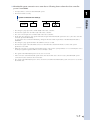
YAMAHA NETWORK BOARD
EtherNet/IP
User s Manual
RCX240
EUS6122100
Ver. 1.00
E122
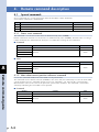
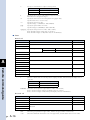
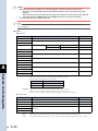
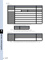
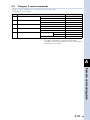
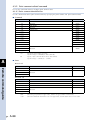
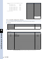
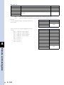
CONTENTS
EtherNet/IP
User’s Manual
Introduction
Introduction
i
Safety Precautions (Always read before starting use)
ii
Warranty
iv
Chapter 1 Outline
1. Features
1-1
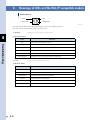
2 .Mechanism
1-2
3. Installing into the robot controller
1-3
4. Part names
1-4
5. I/O assignments of EtherNet/IP compatible module
1-5
6. EtherNet/IP system connection status transition and robot controller status
1-6
Chapter 2 Connection
1. Confirming the EtherNet/IP compatible module settings
2-1
2 .Setting to the EtherNet/IP system specification controller
2-2
2.1 Saving the robot controller data
2-2
2.2 Installing into the robot controller
2-2
2.3 Response when starting up the robot controller
2-2
3. Setting the EtherNet/IP compatible module
2-3
3.1 Making the EtherNet/IP module valid
2-3
3.2 Setting the "Remote_cmd SI05" function
2-4
3.3 Setting the "Output MSG SOW1" function
2-5
3.4 Setting the IP address
2-6
3.5 Setting the subnet mask
2-7
3.6 Setting the gateway
2-8
4. Noise measures
2-9
4.1 LAN cable
2-9
4.2 Mounting the ferrite core
2-9
5. Connecting to the EtherNet/IP system
2-10
T-1
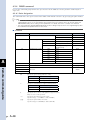
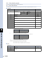
CONTENTS
5.1 Connecting the LAN cable
EtherNet/IP
User’s Manual
2-10
Chapter 3 Communication
1. State when the robot controller power is turned ON
3-1
2 .Communication with the master module
3-2
2.1 Receiving data
3-2
2.2 Transmitting data
3-4
3. Direct connection by emulated serialization on parallel DIO
3.1 Emulated serialization setting on parallel DIO
4. Referring to the communication data
4.1 Referring to the data from the programming box
3-5
3-5
3-8
3-8
Chapter 4 Troubleshooting
1. Check items before starting up the EtherNet/IP system
4-1
2 .Meanings of LEDs on EtherNet/IP compatible module
4-2
3. Troubleshooting
4-3
3.1 Robot controller front panel LED confirmation
4-3
3.2 RPB (programming box) error display confirmation
4-3
3.3 EtherNet/IP compatible module LED confirmation
4-4
3.4 Confirmation from master module
4-4
4. Error messages relating to EtherNet/IP
4-5
Chapter 5 Specifications
1. Profile
5-1
2 .Details of input/output signals
5-3
3. Dedicated input/output signal timing chart
5-6
3.1 Servo ON and emergency stop
3.2 AUTO mode changeover, program reset and program execution
5-7
3.3 Stopping with program interlock
5-8
4. EtherNet/IP compatible module specifications
5. EtherNet/IP specifications
T-2
5-6
5-9
5-10
CONTENTS
EtherNet/IP
User’s Manual
Chapter 6 Appendix
1. Definitions of terms
6-1
2 .EDS files
6-4
Remote command guide
1. Remote command format
A-1
1.1 Remote command specifications
A-1
1.2 Remote status
A-2
2 .Sending and receiving remote commands
A-3
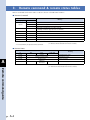
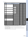
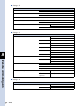
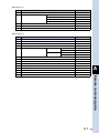
3. Remote command & remote status tables
A-4
4. Remote command description
A-8
4.1 Special commands
A-8
4.1.1 Status reset command
A-8
4.1.2 Main robot current position reference command
A-8
4.1.3 Sub robot current position reference command
A-9
4.2 Category 1 remote commands
A-11
4.2.1 MOVE command
A-12
4.2.1.1 PTP designation
A-12
4.2.1.2 Arch designation
A-15
4.2.1.3 Linear interpolation
A-18
4.2.1.4 Circular interpolation
A-21
4.2.1.5 Direct PTP designation (millimeter units)
A-24
4.2.1.6 Direct PTP designation (pulse units)
A-27
4.2.2 MOVEI command
A-30
4.2.2.1 PTP designation
A-30
4.2.2.2 Direct PTP designation (millimeter units)
A-33
4.2.2.3 Direct PTP designation (pulse units)
A-36
4.2.3 DRIVE command
A-39
4.2.3.1 Point designation
A-39
4.2.3.2 Direct designation (millimeter units)
A-42
4.2.3.3 Direct designation (pulse units)
A-45
4.2.4 DRIVEI command
A-48
4.2.4.1 Point designation
A-48
4.2.4.2 Direct designation (millimeter units)
A-51
4.2.4.3 Direct designation (pulse units)
A-54
4.2.5 Pallet movement command
A-57
4.2.5.1 PTP designation
A-57
T-3
CONTENTS
4.2.5.2 Arch designation
A-60
4.2.6 Jog movement command
A-63
4.2.7 Inching movement command
A-66
4.2.8 Point teaching command
A-69
4.2.9 Absolute reset movement command
A-70
4.2.10 Absolute reset command
A-71
4.2.11 Return-to-origin command
A-72
4.2.12 Servo command
A-74
4.2.13 Manual speed change command
A-75
4.2.14 Auto speed change command
A-76
4.2.15 Program speed change command
A-77
4.2.16 Shift designation change command
A-78
4.2.17 Hand designation change command
A-79
4.2.18 Arm designation change command
A-80
4.2.19 Point display unit designation command
A-81
4.3 Category 2 remote commands
T-4
EtherNet/IP
User’s Manual
A-83
4.3.1 Point-related command
A-84
4.3.1.1 Point data definition
A-84
4.3.1.2 Point data reference
A-86
4.3.2 Point comment-related command
A-88
4.3.2.1 Point comment data definition
A-88
4.3.2.2 Point comment data reference
A-90
4.3.3 Pallet-related command
A-92
4.3.3.1 Pallet data definition
A-92
4.3.3.2 Pallet data reference
A-93
4.3.4 Shift-related command
A-95
4.3.4.1 Shift data definition
A-95
4.3.4.2 Shift data reference
A-97
4.3.5 Hand-related command
A-99
4.3.5.1 Hand data definition
A-99
4.3.5.2 Hand data reference
A-101
4.4 Category 3 remote commands
A-103
4.4.1 Static variable-related command
A-104
4.4.1.1 Assigning a numerical value to a static variable
A-104
4.4.1.2 Assigning a variable to a static variable
A-106
4.4.1.3 Arithmetic operation using numerical data on static variable
A-108
4.4.1.4 Arithmetic operation using variable on static variable
A-110
4.4.1.5 Static variable value reference
A-112
4.4.2 Parameter-related command
A-114
4.4.2.1 Assigning a value to a parameter
A-114
4.4.2.2 Parameter value reference
A-116
4.4.3 Point-related command
A-118
CONTENTS
4.4.3.1 Assigning a point to a parameter
EtherNet/IP
User’s Manual
A-118
4.4.3.2 Point addition/subtraction
A-120
4.4.3.3 Assigning a pallet point
A-122
4.4.4 Element assignment command
A-124
4.4.4.1 Assigning to a point element
A-124
4.4.4.2 Assigning to a shift element
4.5 Category 4 remote commands
A-126
A-128
4.5.1 I/O port commands
A-129
4.5.1.1 Assigning a numerical value to an I/O port
A-129
4.5.1.2 I/O port reference
A-131
4.6 Category 5 remote commands
A-133
4.6.1 Execution program designation
A-134
4.6.2 Program execution
A-135
4.6.3 Program reset
A-136
4.6.4 Program task switching
A-137
4.6.5 Program execution information reference
A-138
4.7 Category 6 remote commands
4.7.1 Version information reference
A-140
A-141
4.7.2 Controller configuration reference
A-142
4.7.3 Servo status reference
A-144
4.7.4 Absolute reset status reference
A-145
4.7.5 Current position reference
A-147
4.7.5.1 Pulse designation
A-147
4.7.5.2 Millimeter designation
A-148
4.7.6 Task status reference
A-150
4.7.7 Task execution line reference
A-151
4.7.8 Message reference
A-152
4.7.9 Speed status reference
A-153
4.7.10 Arm designation status reference
A-154
4.7.11 Arm status reference
A-155
4.7.12 Service mode status reference
A-156
4.7.13 Point unit status reference
A-157
4.7.14 Return-to-origin status reference
A-158
I/O command guide
1. I/O command format
B-1
2 .Sending and receiving I/O commands
B-2
3. I/O command list
B-3
4. I/O command description
B-4
T-5
CONTENTS
4.1 MOVE command
B-4
4.1.1 PTP designation
B-4
4.1.2 Linear interpolation
B-4
4.2 MOVEI command
B-5
4.2.1 PTP designation
B-5
4.3 Pallet movement command
4.3.1 PTP designation
T-6
EtherNet/IP
User’s Manual
B-5
B-5
4.4 Jog movement command
B-6
4.5 Inching movement command
B-7
4.6 Point teaching command
B-7
4.7 Absolute reset movement command
B-8
4.8 Absolute reset command
B-8
4.9 Return-to-origin command
B-9
4.10 Servo command
B-9
4.11 Manual speed change command
B-10
4.12 Auto speed change command
B-10
4.13 Program speed change command
B-11
4.14 Shift designation change command
B-11
4.15 Hand designation change command
B-11
4.16 Arm designation change command
B-12
4.17 Point display unit designation command
B-12
Introduction
Contents
Introduction
Safety Precautions (Always read before starting use)
Warranty
i
ii
iv
Introduction
This manual consists of EtherNet/IP compatible module guide (explanation on wiring or communication),
remote command guide, and I/O command guide.
For information on other devices such as connecting the master module and sequence programming, refer to
the manual for the respective product. For details on operating the robot controller and on the robot program,
thoroughly read the controller user's manual and programming manual supplied with the YAMAHA robot
controller.
i
Introduction
Thank you for purchasing the EtherNet/IP compatible module. This EtherNet/IP compatible module is an
option module that allows the YAMAHA robot controller RCX240 to be connected as an EtherNet/IP system
slave module. The robot controller explained in this manual refers to the RCX240.
Safety Precautions (Always read before starting use)
Introduction
Before using this product, be sure to read this manual carefully as well as robot controller user's manual and
programming manual. Take sufficient precautions to ensure safety and handle the product correctly.
The cautions given in this manual are related to this product. Refer to the robot controller user's manual for
details on the cautions to be taken with the robot controller system using this product.
* The safety precautions are ranked as "WARNING" and "CAUTION" in this manual.
w
c
n
WARNING
Failure to follow WARNING instructions could result in serious injury or death to the operator or
person servicing the product.
CAUTION
Failure to follow CAUTION instructions may result in injury to the operator or person servicing product, or damage
to the product or peripheral equipment.
NOTE
Explains the key point in the operation in a simple and clear manner.
Note that some items described as "CAUTION" may lead to serious results depending on the situation. In any
case, important information that must be observed is explained.
Store this manual where it can be easily referred to, and make sure that it is delivered to the end user.
The EtherNet/IP is a protocol that is jointly controlled by ODVA (Open DeviceNet Vendor Association) and CI (ControlNet International).
■ ■ Precautions for design
w
c
WARNING
• Refer to the EtherNet/IP system Master Module User's Manual and this manual for details on the state
of the EtherNet/IP system and robot controller when a communication error occurs with the EtherNet/IP system, etc. Configure an interlock circuit in the sequence program so that the system, including the robot controller will work safely using the communication status information.
• The SAFETY connector of the robot controller has an emergency stop terminal to trigger emergency stop. Using this terminal, prepare a physical interlock circuit so that the system including the robot controller will work safety.
CAUTION
• The control line and communication cable must not be bound with or placed near the main circuit or power line. Separate these by at least 100mm. Failure to observe this could lead to malfunctions caused by noise.
• The dedicated input of STD.DIO connector provided on the RCX240 controllers will be disabled except for an interlock signal (DI 11). When the external 24V monitor control setting of system parameters is set invalid, the interlock signal (DI 11) will also be disabled.
■ ■ Precautions for installation
w
ii
WARNING
• Always crimp, press-fit or solder the connector wire connections with the maker-designated tool, and securely connect the connector to the module.
• Always shut off all phases of the power supply externally before starting installation or wiring work.
Failure to shut off all phases could lead to electric shocks or product damage.
c
w
c
WARNING
• Always shut off all phases of the power supply externally before starting installation or wiring work. Failure to shut off all phases could lead to electric shocks or product damage.
• Always install the terminal covers enclosed with the product before turning ON the power or operating the product after installation or wiring work. Failure to install the terminal cover could lead to malfunctions.
CAUTION
• Tighten the terminal screws within the specified torque range. A loose terminal screw could lead to short-
circuiting or malfunctioning. If the terminal screw is too tight, short-circuiting or malfunctioning could occur due
to screw damage.
• Make sure that foreign matter, such as cutting chips or wire scraps, do not enter the robot controller.
• The communication cables connected to the EtherNet/IP compatible module must be placed in a conduit or fixed with a clamp. If the cable is not placed in a conduit or fixed with a clamp, the module or cable could be damaged by the cable shifting, movement or unintentional pulling leading to malfunctioning caused by an improper cable connection.
• Do not disconnect the communication cable connected to the EtherNet/IP compatible module by pulling on the cable section.
■ ■ Precautions for starting and maintenance
w
c
WARNING
• Do not touch the terminals while the power is ON. Failure to observe this could lead to malfunctioning.
• Always shut off all phases of the power supply externally before cleaning or tightening the terminal screws. Failure to shut off all phases could lead to electric shocks, product damage or malfunctioning. A loose screw could lead to dropping, short-circuiting or malfunctioning. If the screw is too tight, short-circuiting or malfunctioning could occur due to screw damage.
• Never disassemble or modify any of the robot controller modules.
Failure to observe this could lead to trouble, malfunctioning, injuries or fires.
• Always shut off all phases of the power supply externally before installing or removing the EtherNet/IP compatible module.
Failure to shut off all phases could lead to robot controller trouble or malfunctioning.
• When using the robot controller with the EtherNet/IP compatible module mounted, always mount the enclosed ferrite core for noise measures on the power cable as close to the robot controller as possible. Failure to mount this ferrite core could lead to malfunctioning caused by noise.
CAUTION
The EtherNet/IP system may not function properly if the master module and robot controller power are turned ON
simultaneously. Always turn the robot controller power ON after turning ON the power for the master module ON.
■ ■ Precautions for disposal
c
CAUTION
Dispose of this product as industrial waste.
This manual does not guarantee the implementation of industrial rights or other rights, and does not authorize the implementation
rights. YAMAHA shall not be held liable for any problems regarding industrial rights that occur through the use of the contents given in
this manual.
2012 YAMAHA MOTOR CO., LTD.
iii
Introduction
■ ■ Precautions for wiring
CAUTION
• Use the robot controller within the environment specifications given in the manual. Use in an environment outside the environment specification range could lead to electric shocks, fires, malfunctioning, product damage or deterioration.
• Install the EtherNet/IP compatible module into the robot controller, and securely fix with screws.
• Never directly touch the conductive sections or electric parts inside the controller.
• Accurately connect each connection cable connector to the mounting section.
Failure to observe this could lead to malfunctions caused by a connection fault.
Warranty
For information on the product warranty, please contact your local agent where you purchased your product.
Introduction
iv
Chapter 1 Outline
Contents
1. Features
1-1
2. Mechanism
1-2
3. Installing into the robot controller
1-3
4. Part names
1-4
5. I/O assignments of EtherNet/IP compatible module 1-5
6. EtherNet/IP system connection status transition and robot controller status 1-6
1. Features
EtherNet/IP system
Master module
Controls the entire EtherNet/IP system.
The PLC master module corresponds to this module.
Slave module
Controlled by the master module
in the EtherNet/IP system.
Slave module
Controlled by the master module in the
EtherNet/IP system.
The robot controller corresponds to this module.
23101-S6-00
For details about other units, such as the network settings on the master module side, refer to the user’s manual
for relevant unit.
Additionally, for details about operation of the controller main unit and robot programming, refer to the user’s
manuals for controller and programming.
The EtherNet/IP is a protocol that is jointly controlled by ODVA (Open DeviceNet Vendor Association) and CI
(ControlNet International).
n
NOTE
The dedicated inputs of the STD.DIO connector provided on the RCX240 controller will be disabled except for
the interlock signal (DI 11). When the "Watch on STD.DO DC24V" of the system parameters is set invalid, the
interlock signal (DI 11) will also be disabled.
■ ■ Emulated serialization on parallel DIO
By making the robot controller's internal settings without using a robot program, various I/O devices, such as the sensors
and relays mounted on the robot controller's parallel I/O can be controlled from the PLC as if they were EtherNet/IP
system I/O devices.
c
CAUTION
An emergency stop terminal for hardwire is provided in the SAFETY connector on the robot controller.
For the RCX240, when the EtherNet/IP system is used while STD. DIO is not used (external DC 24V power is not
supplied), the "Watch on STD.DO DC24V" of the system parameters must be set invalid. If it is left valid, the STD.
DIO interlock signal is enabled, causing an error in the robot operation commands.
1-1
1
Outline
This EtherNet/IP is an industrial network that is achieved by combining the standard protocol TCP/IP with the
higher level protocol CIP (Common Industrial Protocol).
Additionally, since the EtherNet/IP uses the standard protocol TCP/IP and Ethernet as lower level protocols,
it can utilize the Ethernet technologies that are widely available in the world.
The EtherNet/IP system connects the robot controllers or distributed input/output systems with dedicated
cables to control these units from the master module.
The EtherNet/IP system allows wiring to be reduced.
1
2. Mechanism
This section describes the mechanism of the communication to provide an understanding of how the robot
controller and master module operate via the EtherNet/IP system.
Outline
Mechanism of communication
ON/OFF information
Master module
Robot controller
(1)
(2)
23102-S6-00
(1) The robot controller's ON/OFF information is sent to the master module via the network.
(2) The master module's ON/OFF information is sent to the robot controller via the network.
* The robot controller monitors the ON/OFF information at a 10ms cycle.
* The ON/OFF information consists of two words each of dedicated I/O words, 14 words each of general-purpose I/O
words as word information, and 16 points each of dedicated I/O points, 96 points each of general-purpose I/O points
as bit information.
If the following is executed with the robot program in the robot controller, the bit information will be sent to the master
module via the EtherNet/IP system by (1).
SO(20)=1
Conversely, if the following is executed with the robot program, the bit information received from the master module via
the EtherNet/IP system will be monitored by (2), and the robot controller will wait for the ON information.
WAIT SI(20)=1
If the following is executed with the robot program in the robot controller, the word information will be sent to the
master module via the EtherNet/IP system by (1).
SOW(2)=256
Conversely, if the following is executed with the robot program, the word information received from the master module
via the EtherNet/IP system will be substituted in integer variable A% by (2).
1-2
A%=SIW(3)
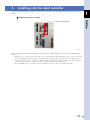
3. Installing into the robot controller
The EtherNet/IP compatible module is installed into an option slot of the robot controller. (Refer to the figure
below.)
1
Installing into the robot controller
Outline
EtherNet/IP compatible module
23103-S6-00
When installing the EtherNet/IP compatible module into the robot controller, strictly observe the following
cautions.
* When three or less option boards are installed, do not stack the EtherNet/IP compatible module on other option board.
Since the EtherNet/IP compatible module is taller than other option boards, it interferes with other option board.
* When four option boards are installed, install the EtherNet/IP compatible module into the OP.3 slot. Additionally, a
custom-ordered front panel is needed. (For details, contact YAMAHA’s Sales Department.)
* The CPU BOARD ASSY is applicable only when the ROM capacity is 4MB or more (KX0-M4210-2XX).
1-3
1
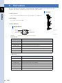
4. Par t names
This section describes the part names of the EtherNet/IP compatible module to be installed in the robot
controller. This module is installed in the option slot of the robot controller.
Part names
Outline
111 RJ45 connector
Connect commercially available LAN cable supporting 10Base-T or 100Base-TX.
1
222 DIP SWITCH
ON OFF
Unused. All switches must be OFF.
2
333 Status Indicators
Status indicators
3
1. Activity
1
3
3. Link
2. Network Status
2
4
4. Module Status
23104-S6-00
23105-S6-00
1.Activity
: Flashing green during packet communication.
2.Network Status :
Status
Description
OFF
Power is OFF or no IP address is found.
Lit in green
Flashing green
Lit in red
Flashing red
Flashing green/red
3.Link
Detects the online and connects other unit.
Detects the online, but does not connect other unit.
Detects serious error, such as IP address duplication.
Time-out occurs during connection with other unit.
Performing the self-test (only when the power is turned ON).
: Lit in green when the link is detected.
4.Module Status :
Status
OFF
Lit in green
Flashing green
Lit in red
Flashing red
Flashing green/red
1-4
Description
Power is OFF.
Connection with the master is correct.
Connection with the master is not established.
Recoverable minor error is detected.
Unrecoverable error is detected.
Performing the self-test (only when the power is turned ON).
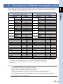
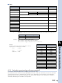
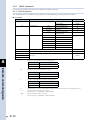
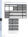
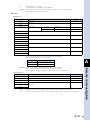
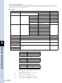
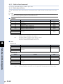
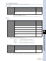
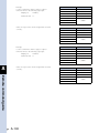
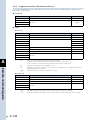
5. I/O assignments of EtherNet/IP compatible module
The following describes the correspondence between the serial input/output of the robot controller and the
input/output data on the EtherNet/IP. The number of bytes to be assigned to the EtherNet/IP compatible
module is 48 byes for input and 48 bytes for output.
Serial input
(Master module → Robot controller)
Robot controller
Master module
Robot controller
Master module
Port number
Address
Port number
Address
SOW(0) *1
SOD(4)
SOD(6)
SOD(8)
SOD(10)
SOD(12)
SOD(14)
*1
m+2
SIW(1)
SOW(2)
m+4
SIW(2)
SOW(3)
m+6
SOW(4)
m+8
SOW(5)
m+10
SOW(6)
m+12
SOW(7)
m+14
SOW(8)
m+16
SOW(9)
m+18
SOW(10)
m+20
SOW(11)
m+22
SOW(12)
m+24
SOW(13)
m+26
SOW(14)
m+28
SOW(15)
m+30
SOW(1)
SOD(2)
SIW(0) *1
m
SID(2)
SID(4)
SID(6)
SID(8)
SID(10)
SID(12)
SID(14)
Outline
Serial output
(Robot controller → Master module)
n
*1
n+2
n+4
SIW(3)
n+6
SIW(4)
n+8
SIW(5)
n+10
SIW(6)
n+12
SIW(7)
n+14
SIW(8)
n+16
SIW(9)
n+18
SIW(10)
n+20
SIW(11)
n+22
SIW(12)
n+24
SIW(13)
n+26
SIW(14)
n+28
SIW(15)
n+30
SO0(7~0)
*2
m+32
7~0
SI0(7~0)
*2
n+32
SO1(7~0)
*2
m+33
7~0
SI1(7~0)
*2
n+33
7~0
m+34
7~0
SI2(7~0)
n+34
7~0
SO2(7~0)
7~0
SO3(7~0)
m+35
7~0
SI3(7~0)
n+35
7~0
SO4(7~0)
m+36
7~0
SI4(7~0)
n+36
7~0
SO5(7~0)
m+37
7~0
SI5(7~0)
n+37
7~0
SO6(7~0)
m+38
7~0
SI6(7~0)
n+38
7~0
SO7(7~0)
m+39
7~0
SI7(7~0)
n+39
7~0
SO10(7~0)
m+40
7~0
SI10(7~0)
n+40
7~0
SO11(7~0)
m+41
7~0
SI11(7~0)
n+41
7~0
SO12(7~0)
m+42
7~0
SI12(7~0)
n+42
7~0
SO13(7~0)
m+43
7~0
SI13(7~0)
n+43
7~0
SO14(7~0)
m+44
7~0
SI14(7~0)
n+44
7~0
m+45
7~0
SI15(7~0)
n+45
7~0
m+46
7~0
Reserved.
*3
n+46
7~0
Reserved.
*3
n+47
7~0
SO15(7~0)
Reserved.
*3
Reserved.
*3
m+47
7~0
m: Start address of the input area assigned to the master module
n : Start address of the output area assigned to the master module
*1:Since this port is used as dedicated command, it cannot be used as general-purpose input/output data.
*2:Since this port is used as dedicated input/output, it cannot be used as general-purpose input/output data.
*3:Reserved area.
n
1
NOTE
• Each address is 8-bit data.
• SOn() and SIn() are handled as unsigned 8-bit integer data.
• SOW(n) and SIW(n) are handled as unsigned 16-bit integer data.
• SOD(n) and SID(n) are handled as signed 32-bit integer data.
• The upper word and lower word of SOD(n) correspond to SOW(n+1) and SOW(n), respectively.
• The upper word and lower word of SID(n) correspond to SIW(n+1) and SIW(n), respectively.
• In the RCX240, the dedicated inputs of STD.DIO provided on the controller will be disabled except for the interlock signal (DI11). When the external 24V monitor control of the system parameters is set invalid, the interlock signal (DI11) will also be disabled.
1-5
1
6. EtherNet/IP system connection status transition and robot controller status
The EtherNet/IP system specification robot controller always starts the operation in the servo OFF state after
the power has been turned ON.
Outline
111 Normal state of EtherNet/IP system connection when the robot controller power is turned ON
System connection normal state
Robot
controller
Master module
23106-S6-00
• The emergency stop/interlock signals in the EtherNet/IP system are valid.
• When the SAFE mode is enabled, the service mode input signal is made valid with SI (02) in the EtherNet/IP system.
• The emergency stop terminal in the SAFETY connector is valid.
• The interlock signal in the STD. DIO connector is valid unless the external 24V monitor control of the system
parameters is set invalid.
• When the SAFE mode is enabled and the external 24V monitor control of the system parameters is left valid, the
service mode input signal is made valid with DI(02) in the SAFETY connector.
* The signals in the EtherNet/IP system are sent and received.
222 Transition from the EtherNet/IP system normal connection state to the EtherNet/IP system connection error state
System connection error state (1)
Robot
controller
Master module
Robot
controller
Master module
Robot
controller
Master module
or
23107-S6-00
• The emergency stop input turns off with SI (00) in the robot controller.
• The interlock signal turns off with SI (10) in the robot controller.
• The service mode input turns off with SI (02) in the robot controller.
• The emergency stop terminal in the SAFETY connector is valid.
• The interlock signal in the STD. DIO connector is valid when the external 24V monitor control of the system
parameters is left valid.
• When the SAFE mode is enabled and the external 24V monitor control of the system parameters is left valid, the
service mode input signal is made valid with DI (02) in the SAFETY connector.
* The signals in the EtherNet/IP system are not sent or received.
* If the connection to the EtherNet/IP system transits from the normal state to the error state, the EtherNet/IP system
connection must be returned to the normal state.
* The signals in the EtherNet/IP system can be sent and received when the EtherNet/IP system connection is recovered to
the normal state.
1-6
333 EtherNet/IP system connection error state due to following factors when the robot controller power is turned ON.
• It is impossible to connect to the EtherNet/IP system.
1
• The master module is faulty.
System connection error state (2)
Master module
Robot
controller
Master module
23108-S6-00
• The emergency stop input turns off with SI(00) in the robot controller.
• The interlock signal turns off with SI (10) in the robot controller.
• The service mode input turns off with SI (02) in the robot controller.
• At this time, the emergency stop signal and interlock signal in the EtherNet/IP system turn off. So, the robot controller
cannot be operated individually.
To operate the robot controller individually, change the "Board condition" parameter of the EtherNet/IP module to
"INVALID".
• The emergency stop signal terminal in the SAFETY connector is valid.
• The interlock signal in the STD. DIO connector is valid when the external 24V monitor control of the system
parameters is left valid.
• When the safe mode is set and the external 24V monitor control of the system parameters is not set invalid, the service
mode input signal through the SAFETY connector DI (02) is valid.
* The signals in the EtherNet/IP system are not sent or received.
* If the connection to the EtherNet/IP system transits from the normal state to the error state, the EtherNet/IP system
connection must be returned to the normal state.
* The signals in the EtherNet/IP system can be sent and received when the EtherNet/IP system connection is recovered to
the normal state.
1-7
Outline
Robot
controller
Chapter 2 Connection
Contents
1. Confirming the EtherNet/IP compatible module settings 2-1
2. Setting to the EtherNet/IP system specification controller 2-2
2.1 Saving the robot controller data
2-2
2.2
Installing into the robot controller
2-2
2.3
Response when starting up the robot controller
2-2
3. Setting the EtherNet/IP compatible module
2-3
3.1 Making the EtherNet/IP module valid
2-3
3.2 Setting the "Remote_cmd SI05" function
2-4
3.3 Setting the "Output MSG SOW1" function
2-5
3.4 Setting the IP address
2-6
3.5 Setting the subnet mask
2-7
3.6 Setting the gateway
2-8
4. Noise measures
2-9
4.1 LAN cable
2-9
4.2 Mounting the ferrite core
2-9
5. Connecting to the EtherNet/IP system
5.1 Connecting the LAN cable
2-10
2-10
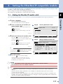
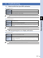
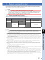
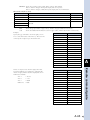
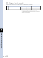
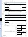
1. Confirming the EtherNet/IP compatible module settings
Whether or not an EtherNet/IP compatible module is installed in the robot controller can be confirmed from
the RPB programming box (hereafter referred to as "RPB"). The following describes the confirmation steps.
■ ■ Operation
1 Select "SYSTEM".
Press the
Step 1
2
“SYSTEM” screen
key on the RPB to change the
SYSTEM V10.50
function menu, and then press the
−−−−−−−−−−−−−−−−−−−−−−−−−−−−−−−−−−−−−−−−
24201-S6-00
2 Confirm that the EtherNet/IP
Robot = YK250X Axis = XYZR
Standard= SRAM/364kB, DIO_N
Opt−ifo = ENet_IP
PARAM CMU OPTION INIT DAIGNOS
module is installed.
"ENet_IP" is shown in "Opt-ifo" when the
EtherNet/IP module is installed properly.
24202-S6-00
Step 2
Confirming that the EtherNet/IP module is installed
SYSTEM V10.50
−−−−−−−−−−−−−−−−−−−−−−−−−−−−−−−−−−−−−−−−
Robot = YK250X Axis = XYZR
Standard= SRAM/364kB, DIO_N
Opt−ifo = ENet_IP
PARAM CMU OPTION INIT DAIGNOS
Confirm.
2-1
Connection
(SYSTEM) key. The "SYSTEM" screen will
appear.
2. Setting to the EtherNet/IP system specification controller
When connecting the EtherNet/IP compatible module to an existing robot controller, the EtherNet/IP
compatible module must be installed. Check the EtherNet/IP system specifications using the procedure
described in "1. Confirming the EtherNet/IP compatible module settings" of Chapter 2 in this guide.
2
2.1
Connection
2.2
Saving the robot controller data
Before installing the EtherNet/IP compatible module into the robot controller, be sure to save the data stored in
the robot controller into an external memory using the VIP+ software, etc.
Installing into the robot controller
Install the EtherNet/IP compatible module into the root controller. (Refer to "3. Installing into the robot
controller" in Chapter 1 of this guide.) After the EtherNet/IP compatible module has been installed, set the IP
address, subnet mask, and gateway for the EtherNet/IP compatible module while referring to "3. Setting the
EtherNet/IP compatible module" in Chapter 2 of this guide.
2.3
Response when starting up the robot controller
The robot controller will always start up in the option board setting error state after the EtherNet/IP compatible
module has been installed into the robot controller. Follow the steps below to make the settings.
■ ■ Procedure
1 Check the controller connections,
and then turn ON the power.
Connect all input connectors on the front
panel of the controller, and then turn ON the
power.
2 Select "YES".
Step 2
The message, "change OptionSlot OK?", will
appear on the RPB. Select "YES".
After you have selected "YES", the "MANUAL"
screen will appear.
Checking the option setting change
POWER ON V10.50
−−−−−− −−−−
12.70:Incorrect option setting
24203-S6-00
TIP
• The initial value of the "Board condition" parameters of the EtherNet/IP module is "INVALID".
• If the controller does not operate properly due to a memory error, etc., load the data saved in section 2.1. For details about how to load the data, refer to the user’s manual for controller.
n
2-2
NOTE
For details about how to load the support software
VIP+, refer to the user’s manual for VIP+.
change OptionSlot OK? YES NO
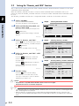
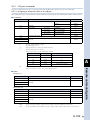
3. Setting the EtherNet/IP compatible module
To connect the EtherNet/IP system to the EtherNet/IP system specification controller, it is necessary to set the
IP address, subnet mask, and gateway parameters.
These settings are made with the RPB (programming box).
The settings are valid after the controller has been restarted.
3.1
Making the EtherNet/IP module valid
To use the EtherNet/IP module, it is necessary to set the EtherNet/IP board valid using the parameters.
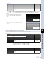
Select "SYSTEM>PARAM>OP.BRD".
The option board list screen will appear.
2 Select an EtherNet IP module you
want to make valid.
Move the cursor to "ENet_IP" and press the
(SELECT) key.
The Ethernet/IP module setting screen will
appear.
24204-S6-00
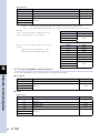
3 Make the Ethernet/IP module valid.
Press the
Selecting EtherNet/IP module
SYSTEM>PARAM>OP.BRD V10.50
−−−−−−−−−−−−−−−−−−−−−−−−−−−−−−−−−−−−−−−−
1. ENet_IP VALID
2. −−−−−
3. −−−−−
4. −−−−−
SELECT
key (cursor down key) to
move the cursor to "1. Board condition" and
press the
(EDIT) key.
Press the
(VALID) key. The controller
will recognize the EtherNet/IP module.
24205-S6-00
TIP
If you press the
Step 2
(INVALID) key, the controller
does not recognize the EtherNet/IP module.
Step 3
Making EtherNet/IP module valid
SYSTEM>PARAM>OP.BRD>SELECT V10.52
−−−−−−−−−−−−−−−−−−−−−−−−−−−−−−−−−−−−−−−−
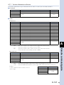
1.Board condition INVALID 2.Remote_cmd SI05 VALID
3.Output MSG SOW1 INVALID
4.IP address 192. 168. 0. 2
5.Subnet mask 255. 255. 255. 0
6.Gateway 192. 168. 0. 1
INVALID VALID 4 Exit the setting.
Press the
key to exit the setting.
Subsequently, to set other item, use the
cursor up or down key to select a desired
parameter you want to set.
c
n
CAUTION
• The "Board condition" you have changed becomes valid after the controller is restarted.
• This parameter has been set at "INVALID" at shipment.
NOTE
• When using the controller without connecting to an EtherNet/IP, set the "Board condition" parameter to "INVALID".
• When the "Board condition" parameter is set to "INVALID", the dedicated input/output of the STD.DIO connector becomes enabled.
• When the "Board condition" parameter is set to "VALID", the dedicated input (except DI11 for RCX240) of the STD.DIO connector becomes disabled. However, the emergency stop input signal (DI00), interlock input (DI11), and service mode input (DI02) stay enabled.
2-3
Connection
1 Select "OP.BRD".
2
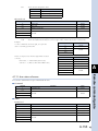
3.2
2
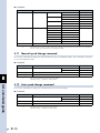
Setting the "Remote_cmd SI05" function
This section describes how to make the remote command and I/O command function valid that uses the word
information and bit information.
When the "Remote_cmd SI05" function is valid, the remote command and I/O command can be used.
Conversely, when the "Remote_cmd SI05" function is invalid, the remote command and I/O command cannot
be used.
This "Remote_cmd SI05" function and "3. Output MSG SOW1" cannot be set valid at the same time.
1 Select "OP.BRD".
Select "SYSTEM>PARAM>OP.BRD".
The option board list screen will appear.
Connection
2 Select an EtherNet IP module you
want to make valid.
Move the cursor to "ENet_IP" and press the
(SELECT) key.
The Ethernet/IP module setting screen will
appear.
Step 2
Selecting EtherNet/IP module
SYSTEM>PARAM>OP.BRD V10.52
−−−−−−−−−−−−−−−−−−−−−−−−−−−−−−−−−−−−−−−−
1. ENet_IP VALID
2. −−−−−
3. −−−−−
4. −−−−−
SELECT
24206-S6-00
3 Select "2. Remote_cmd SI05".
Use the
Selecting “Remote_cmd SI05”
key (cursor down key) to move
the cursor to "2. Remote_cmd SI05" and press
the
Step 3
(EDIT) key.
"2. Remote_cmd SI05" is then selected.
24207-S6-00
4 Select "2. Remote_cmd SI05" valid
SYSTEM>PARAM>OP.BRD>SELECT V10.52
−−−−−−−−−−−−−−−−−−−−−−−−−−−−−−−−−−−−−−−−
1.Board condition VALID
2.Remote_cmd SI05 VALID 3.Output MSG SOW1 INVALID
4.IP address 192. 168. 0. 2
5.Subnet mask 255. 255. 255. 0
6.Gateway 192. 168. 0. 1
or invalid.
Press the
(VALID) key to make the
remote command and I/O command
function valid.
Press the
24208-S6-00
5 Exit the setting.
key to exit the setting.
Subsequently, to set other item, use the
cursor up or down key to select a desired
parameter you want to set.
c
n
2-4
Step 4
Selecting “Remote_cmd SI05” valid/invalid
(INVALID) key to make the
remote command and I/O command
function invalid.
Press the
EDIT JUMP
SYSTEM>PARAM>OP.BRD>SELECT V10.52
−−−−−−−−−−−−−−−−−−−−−−−−−−−−−−−−−−−−−−−−
1.Board condition VALID
2.Remote_cmd SI05 VALID
3.Output MSG SOW1 INVALID
4.IP address 192. 168. 0. 2
5.Subnet mask 255. 255. 255. 0
6.Gateway 192. 168. 0. 1
INVALID VALID
CAUTION
• This parameter is compatible with the RCX240 software version 10.52 or higher.
• This parameter has been set at "VALID" at shipment.
NOTE
• For details about remote commands and I/O commands, refer to the sections, "Remote command guide" and "I/O command guide", in this manual.
• When the "Remote_cmd SI05" function is made invalid, the "Output MSG SOW1" function cannot be used.
Conversely, when the "Output MSG SOW1" function is made valid, the "Remote_cmd SI05" function cannot be used.
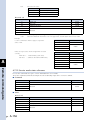
3.3
Setting the "Output MSG SOW1" function
This section describes how to make the function valid or invalid that outputs the message number to be
displayed on the RPB to the word information SOW (1).
When the "Output MSG SOW1" function is valid, the message number to be displayed on the RPB is output to
the SOW (1).
Conversely, when the "Output MSG SOW1" function is invalid, the message number to be displayed on the
RPB is not output to the SOW (1).
This "Output MSG SOW1" function and "2. Remote_cmd SI05" cannot be set valid at the same time.
1 Select "OP.BRD".
2 Select an EtherNet IP module you
want to make valid.
Move the cursor to "ENet_IP" and press the
(SELECT) key.
The Ethernet/IP module setting screen will
appear.
Step 2
Selecting EtherNet/IP module
SYSTEM>PARAM>OP.BRD V10.52
−−−−−−−−−−−−−−−−−−−−−−−−−−−−−−−−−−−−−−−−
1. ENet_IP VALID
2. −−−−−
3. −−−−−
4. −−−−−
SELECT
24209-S6-00
3 Select "3. Output MSG SOW1".
Use the
key (cursor down key) to move
the cursor to "3. Output MSG SOW1" and
press the
(EDIT) key.
"3. Output MSG SOW1" is then selected.
24210-S6-00
4 Select "3. Output MSG SOW1"
valid or invalid.
Press the
(VALID) key to make the
24211-S6-00
5 Exit the setting.
key to exit the setting.
Subsequently, to set other item, use the
cursor up or down key to select a desired
parameter you want to set.
c
n
EDIT JUMP
Selecting “Output MSG SOW1” valid/invalid
(INVALID) key to make the
"Output MSG SOW1" function invalid.
Press the
Selecting “Output MSG SOW1”
SYSTEM>PARAM>OP.BRD>SELECT V10.52
−−−−−−−−−−−−−−−−−−−−−−−−−−−−−−−−−−−−−−−−
1.Board condition VALID
2.Remote_cmd SI05 VALID
3.Output MSG SWW1 INVALID
4.IP address 192. 168. 0. 2
5.Subnet mask 255. 255. 255. 0
6.Gateway 192. 168. 0. 1
Step 4
"Output MSG SOW1" function valid.
Press the
Step 3
SYSTEM>PARAM>OP.BRD>SELECT V10.52
−−−−−−−−−−−−−−−−−−−−−−−−−−−−−−−−−−−−−−−−
1.Board condition VALID
2.Remote_cmd SI05 VALID
3.Output MSG SWW1 INVALID
4.IP address 192. 168. 0. 2
5.Subnet mask 255. 255. 255. 0
6.Gateway 192. 168. 0. 1
INVALID VALID
CAUTION
• This parameter is compatible with the RCX240 software version 10.52 or higher.
• This parameter has been set at "INVALID" at shipment.
NOTE
• For details about codes output by the "Output MSG SOW1" function, refer to the error messages stated in the user’s manual for controller.
• When the "Remote_cmd SI05" function is made invalid, the "Output MSG SOW1" function cannot be used.
Conversely, when the "Output MSG SOW1" function is made valid, the "Remote_cmd SI05" function cannot be used.
2-5
Connection
Select "SYSTEM>PARAM>OP.BRD".
The option board list screen will appear.
2
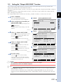
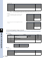
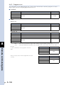
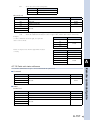
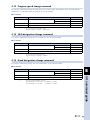
3.4
Setting the IP address
Set the IP address.
The IP address is a unique number assigned to each unit that identifies multiple units connected to the
network. So, the IP address needs to be set and controlled so that it does not overlap with that of other unit.
2
1 Select "OP.BRD".
Select "SYSTEM>PARAM>OP.BRD".
The option board list screen will appear.
2 Select an EtherNet IP module you
Step 2
Selecting EtherNet/IP module
want to make valid.
Connection
Move the cursor to "ENet_IP" and press the
(SELECT) key.
The Ethernet/IP module setting screen will
appear.
24212-S6-00
3 Select "4. IP address".
Use the
SYSTEM>PARAM>OP.BRD V10.50
−−−−−−−−−−−−−−−−−−−−−−−−−−−−−−−−−−−−−−−−
1. ENet_IP VALID 2. −−−−−
3. −−−−−
5. −−−−−
SELECT
key (cursor down key) to move
the cursor to "4. IP address" and press the
Step 3
Selecting “4. IP address”
(EDIT) key.
The IP address entry screen will appear.
24213-S6-00
4 Enter an IP address.
Enter a desired IP address with the numeric
keys (0 to 9) and period (.) key.
After you have entered the IP address, press
the
SYSTEM>PARAM>OP.BRD>SELECT V10.52
−−−−−−−−−−−−−−−−−−−−−−−−−−−−−−−−−−−−−−−−
1.Board condition VALID
2.Remote_cmd SI05 VALID
3.Output MSG SOW1 INVALID
4.IP address 192. 168. 0. 2
5.Subnet mask 255. 255. 255. 0
6.Gateway 192. 168. 0. 1
key.
EDIT JUMP
24214-S6-00
5 Exit the setting.
Press the
Entering IP address
key to exit the setting.
Subsequently, to set other item, use the
or
Step 4
key (cursor up or down key) to select
a desired parameter you want to set.
SYSTEM>PARAM>OP.BRD>SELECT V10.52
−−−−−−−−−−−−−−−−−−−−−−−−−−−−−−−−−−−−−−−−
1.Board condition VALID
2.Remote_cmd SI05 VALID
3.Output MSG SOW1 INVALID
4.IP address 192. 168. 0. 2
5.Subnet mask 255. 255. 255. 0
6.Gateway 192. 168. 0. 1
Enter IP address >192. 168. 0. 2 2-6
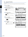
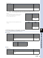
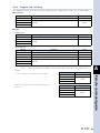
3.5
Setting the subnet mask
Select the subnet mask.
The subnet mask is used to divide the network into small units.
Step 2
Selecting EtherNet/IP module
1 Select "OP.BRD".
Select "SYSTEM>PARAM>OP.BRD".
The option board list screen will appear.
2 Select an EtherNet IP module you
want to make valid.
Move the cursor to "ENet_IP" and press the
SYSTEM>PARAM>OP.BRD V10.50
−−−−−−−−−−−−−−−−−−−−−−−−−−−−−−−−−−−−−−−−
1. ENet_IP VALID
2. −−−−−
3. −−−−−
4. −−−−−
The Ethernet/IP module setting screen will
appear.
SELECT
Step 3
Selecting “5. Subnet mask”
24215-S6-00
3 Select "5. Subnet mask".
Use the
key (cursor down key) to move
the cursor to "5. Subnet mask" and press the
(EDIT) key.
The subnet mask entry screen will appear.
SYSTEM>PARAM>OP.BRD>SELECT V10.52
−−−−−−−−−−−−−−−−−−−−−−−−−−−−−−−−−−−−−−−−
1.Board condition VALID
2.Remote_cmd SI05 VALID
3.Output MSG SOW1 INVALID
4.IP address 192. 168. 0. 2
5.Subnet mask 155. 255. 255. 0
6.Gateway 192. 168. 0. 1
24216-S6-00
4 Enter a subnet mask.
Enter a desired subnet mask with the
numeric keys (0 to 9) and period (.) key.
After you have entered the subnet mask,
press the
key.
24217-S6-00
5 Exit the setting.
Press the
key to exit the setting.
Subsequently, to set other item, use the
or
n
n
Step 4
Entering subnet mask
SYSTEM>PARAM>OP.BRD>SELECT V10.52
−−−−−−−−−−−−−−−−−−−−−−−−−−−−−−−−−−−−−−−−
1.Board condition VALID
2.Remote_cmd SI05 VALID
3.Output MSG SOW1 INVALID
4.IP address 192. 168. 0. 2
5.Subnet mask 155. 255. 255. 0 6.Gateway 192. 168. 0. 1
key (cursor up or down key) to select
a desired parameter you want to set.
c
EDIT JUMP
Enter subnet mask >255. 255. 255. 0
CAUTION
The IP address, subnet mask, and gateway you have changed become valid after the controller is restarted.
When connecting the robot controller to an existing network, be sure to check with the network administrator for
the IP address, subnet mask, and gateway settings.
NOTE
The IP address is separated into network address and host address sections. The network address section is
extracted from the IP address by AND processing with the subnet mask. The remaining portion is the host address
section. Devices belonging to the same network must all be set to have the same network address. The host
address, however, should be different for every device and set so that no two devices have the same number. The
first and the last host address numbers are reserved for the system. So, be sure not to set these as the IP address.
When the IP address for example is 192.168.0.10 and the subnet mask is 255.255.255.0, the network address section
is found to be 192.168.0 and the host address section to be 10 by means of AND processing with the subnet mask.
In this case, the network address section of all other devices belonging to that network must all be 192.168.0.
The host address section of those other devices on the other hand, must be set to a number other than 10. The
number 0 and 255 are reserved, so do not use them for setting the host address.
So, when a device having an IP address of 192.168.0.10 and a subnet mask of 255.255.255.0 belongs to a particular
network and you want to add another device to that network, then you would assign IP addresses from among
192.168.0.1 to 192.168.0.9 and 192.168.0.11 to 192.168.0.254.
NOTE
The EtherNet/IP module for RCX240 series is not usable with IP address auto acquisition functions such as DHCP
and BOOTP. In this case, you must set the IP address manually.
2-7
Connection
(SELECT) key.
2
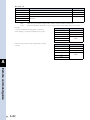
3.6
Setting the gateway
Set the gateway. Actually, specify the IP address of the router.
The router is a device that relays the information from a certain network to other network when there are
multiple networks.
2
1 Select "OP.BRD".
Select "SYSTEM>PARAM>OP.BRD".
The option board list screen will appear.
2 Select an EtherNet IP module you
Step 2
Selecting EtherNet/IP module
want to make valid.
Connection
Move the cursor to "ENet_IP" and press the
(SELECT) key.
The Ethernet/IP module setting screen will
appear.
24218-S6-00
3 Select "6. Gateway".
Use the
SYSTEM>PARAM>OP.BRD V10.50
−−−−−−−−−−−−−−−−−−−−−−−−−−−−−−−−−−−−−−−−
1. ENet_IP VALID
2. −−−−−
3. −−−−−
4. −−−−−
SELECT
key (cursor down key) to move
the cursor to "6. Gateway" and press the
Step 3
Selecting “6. Gateway”
(EDIT) key.
The gateway IP address entry screen will
appear.
24219-S6-00
4 Enter a gateway IP address.
Enter a desired gateway IP address with the
numeric keys (0 to 9) and period (.) key.
After you have entered the gateway IP
address, press the
EDIT JUMP
key.
24220-S6-00
5 Exit the setting.
Press the
key to exit the setting.
Subsequently, to set other item, use the
or
key (cursor up or down key) to select
a desired parameter you want to set.
c
2-8
SYSTEM>PARAM>OP.BRD>SELECT V10.52
−−−−−−−−−−−−−−−−−−−−−−−−−−−−−−−−−−−−−−−−
1.Board condition VALID
2.Remote_cmd SI05 VALID
3.Output MSG SOW1 INVALID
4.IP address 192. 168. 0. 2
5.Subnet mask 255. 255. 255. 0
6.Gateway 192. 168. 0. 1
CAUTION
Any appropriate gateway address can be used as
long as the network is not connected to other
networks. (However, use an IP address that has not
yet been assigned to other devices.)
When connecting the robot controller to an
already existing network, always check with the
network administrator before making IP address,
subnet mask, and gateway settings.
The EtherNet/IP module for RCX240 series uses a
private address as the IP address default setting.
This default value cannot be used as it is on the
Internet. So, when connecting to the Internet,
always be sure to change the IP address of the
robot controller to a global address.
Step 4
Entering gateway
SYSTEM>PARAM>OP.BRD>SELECT V10.52
−−−−−−−−−−−−−−−−−−−−−−−−−−−−−−−−−−−−−−−−
1.Board condition VALID
2.Remote_cmd SI05 VALID
3.Output MSG SOW1 INVALID
4.IP address 192. 168. 0. 2
5.Subnet mask 255. 255. 255. 0
6.Gateway 192. 168. 0. 1
Enter gateway >192. 168. 0. 1
4. Noise measures
Two ferrite cores must be mounted on the shielded LAN cable when connecting to the EtherNet/IP system.
4.1
LAN cable
The EtherNet/IP is connected in a wide zone, from the enterprise zone to the manufacturing zone. So, an
appropriate LAN cable that prevents noise from entering its inside must be used.
Conditions:•C AT5E grade or higher
•T wist-pair
•D ual shielded
Recommended cables:N WSMC5E-SON-S2SB-SB-*** (Straight cable) (Manufacturer: MiSUMi)
NWSMC5E-SON-C2SB-SB-*** (Cross cable) (Manufacturer: MiSUMi)
(* shows the cable length. A desired cable length can be specified at intervals of 0.1m in a range of 0.5 to 100m.)
4.2
Mounting the ferrite core
Mount one ferrite core at both ends of the LAN cable.
w
WARNING
Completely shut down the power supply to the input power cable before starting this work.
■ ■ Procedure
1 Mount the ferrite core.
Mount the ferrite core at both ends of the LAN cable as shown in the figure below. At this time, place
the ferrite core as close to the robot controller and HUB as possible.
2 Secure the ferrite core with a cable tie, etc.
Secure the mounted ferrite core with a cable tie, etc.
Mounting ferrite core
RCX240
HUB
Ferrite core
23201-S6-00
2-9
Connection
2
5. Connecting to the EtherNet/IP system
5.1
2
w
Connecting the LAN cable
WARNING
Before connecting the cable, completely shut down the power supplied to the robot controller.
Connection
Insert the modular jack of the LAN cable recommended in section 4.1, LAN cable, into the modular connector
of the controller until a click sounds. In the same manner, connect the modular jack into the modular
connector of the hub.
c
c
CAUTION
In the EtherNet/IP, it is recommended to use a hub that connects the chassis of the LAN connector to the PE.
YAMAHA also conducts the functional check with the hub that connects the chassis to the PE.
CAUTION
The maximum length of the cable between the hub and controller is 100 m.
When connecting the LAN cable, be sure to thoroughly read the user’s manuals for mating units, such as personal
computer and sequencer, and peripheral units, such as hub.
MEMO
It is recommended to connect the mating unit with the straight cable through the hub. It is also possible to use
the cross-cable to directly connect the mating unit without use of the hub. At this time, however, the
communication with the mating unit may not be performed correctly depending on the type of the LAN
adaptor.
2-10
Chapter 3 Communication
Contents
1. State when the robot controller power is turned ON 3-1
2. Communication with the master module
2.1
Receiving data
2.2 Transmitting data
3-2
3-2
3-4
3. Direct connection by emulated serialization on parallel DIO 3-5
3.1 Emulated serialization setting on parallel DIO
4. Referring to the communication data
4.1
Referring to the data from the programming box
3-5
3-8
3-8
1. State when the robot controller power is turned ON
The EtherNet/IP system specification robot controller always starts the operation in the servo OFF state after
the power has been turned ON.
111 When the connection to the EtherNet/IP system is correctly established.
The following conditions must be satisfied to correctly connect to the EtherNet/IP system.
• The EtherNet/IP system cable must be physically connected.
• The IP address, subnet mask, and gateway must be set correctly.
• The master module is operating correctly.
222 When the connection to the EtherNet/IP system is incorrectly established.
If connected to the EtherNet/IP system incorrectly, the following may be the cause.
• The EtherNet/IP system cable is not physically connected.
• The IP address, subnet mask, or gateway is not set correctly.
• The master module is not operating correctly.
If connected to the EtherNet/IP system incorrectly, the LEDs on the EtherNet/IP compatible module show the error state.
This also occurs when the master module is not operating correctly.
At this time, the emergency stop signal and interlock signal in the EtherNet/IP system turn off. So, the robot controller
cannot be operated individually.
To operate the robot controller individually, change the "Board condition" parameter of the EtherNet/IP module to
"INVALID".
The emergency stop signal terminal in the SAFETY connector is always valid.
In the RCX240, the interlock signal of STD.DIO is valid unless the external 24V monitor control of the system parameters
is set invalid.
In the RCX240, when the SAFE mode is enabled and the external 24V monitor control of the system parameters is not set
invalid, the SERVICE mode input signal is made valid with DI (02) in the SAFETY connector.
When the SAFE mode is enabled, the SERVICE mode input signal in the EtherNet/IP system cannot be set invalid. So,
change the SERVICE mode setting of the system parameters for operation. Always change this parameter with great care.
MEMO
For details about LED indications, see Chapter 4 of this guide.
3-1
3
Communication
When connected to the EtherNet/IP system correctly, the LEDs on the EtherNet/IP compatible module show the normal
state.
At this time, the emergency stop signal and interlock signal in the EtherNet/IP system become valid, so both signals need
to be turned ON in the connection process.
The emergency stop terminal in the SAFETY connector is always valid.
In the RCX240, the interlock signal of STD.DIO is valid unless the external 24V monitor control of the system parameters
is set invalid.
When the SAFE mode is enabled, the SERVICE mode input signal is made valid with SI(02) in the EtherNet/IP system. In
the RCX240, when the SAFE mode is enabled and the external 24V monitor control of the system parameters is not set
invalid, the SERVICE mode input signal is made valid with DI(02) of the SAFETY connector.
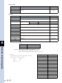
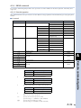
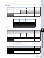
2. Communication with the master module
This section describes the communication with the master module using the robot program when connected to
the EtherNet/IP system correctly.
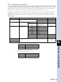
2.1
Receiving data
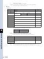
The data in the output area of the master module is read via the serial input ports of the robot controller.
The following shows the correspondence between the output area of the master module and the serial input
port of the robot controller.
Address of master
module output area
3
Serial input port No. of robot
controller
n
SIW(0)
Address of master
module output area
n+32
Serial input port No. of robot
controller
SI0(7~0)
n+2
SIW(1)
n+33
SI1(7~0)
n+4
SIW(2)
n+34
SI2(7~0)
Communication
n+6
n+8
n+10
n+12
n+14
n+16
n+18
n+20
n+22
n+24
n+26
n+28
n+30
SID(2)
SID(4)
SID(6)
SID(8)
SID(10)
SID(12)
SID(14)
SIW(3)
n+35
SI3(7~0)
SIW(4)
n+36
SI4(7~0)
SIW(5)
n+37
SI5(7~0)
SIW(6)
n+38
SI6(7~0)
SIW(7)
n+39
SI7(7~0)
SIW(8)
n+40
SI10(7~0)
SIW(9)
n+41
SI11(7~0)
SIW(10)
n+42
SI12(7~0)
SIW(11)
n+43
SI13(7~0)
SIW(12)
n+44
SI14(7~0)
SIW(13)
n+45
SI15(7~0)
SIW(14)
SIW(15)
n : Start address of the output area assigned to the master module
c
CAUTION
Before communicating with the master module, be sure to check the setting while referring to the user’s manual
for PLC.
When reading the bit information from the output area of the master module with the robot controller, write
the following commands in the robot program in the same manner as the DI input port.
WAIT command
Assignment statement
Example: To wait for bit 0 of the address (n+34) to turn ON.
WAIT SI (20) = 1������������������ The robot program will wait for SI(20) to turn ON.
Example: To read the address (n+34)0 to (n+34)7 data into variable A.
A = SI2 ()����������������������������� The SI2() data will be converted into a decimal value and assigned to
variable A. If SI2() is 7Fh, variable A will be 127.
n
NOTE
The SI statement in the robot language can be defined from SI0() to SI27(), but the EtherNet/IP compatible
module accepts from SI0() to SI15().
When reading the word information from the output area of the master module with the robot controller, create
the robot program using the assignment statement.
Example: To read the address (n+4) word data into variable B.
B = SIW (2)�������������������������� The SIW(2) data will be assigned to variable B as a decimal value. If
SIW(2) is 01FFh, variable B will be 511.
3-2
Example: To read the address (n+4) and (n+6) double word data into variable C.
C = SID (2)��������������������������� The SIW(2) and SIW(3) data will be assigned to variable C as a decimal
value. If SIW(2) is 0010h and SIW(3) is 0001h, variable C will be
65552.
n
NOTE
The word data written with SIW(n) has the uncoded little endian format.
The double word data written with SID(n) has the coded little endian format.
3
Communication
3-3
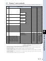
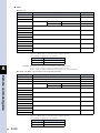
2.2
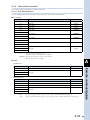
Transmitting data
The serial output port data of the robot controller is transmitted to the input area of the master module.
The correspondence between the serial output port of the robot controller and the input area of the master
module is shown below.
Address of master
module input area
Address of master
module input area
Serial output port No. of
robot controller
m
SOW(0)
m+32
SO0(7~0)
m+2
SOW(1)
m+33
SO1(7~0)
m+4
SOW(2)
m+34
SO2(7~0)
SOW(3)
m+35
SO3(7~0)
SOW(4)
m+36
SO4(7~0)
SOW(5)
m+37
SO5(7~0)
m+6
3
Serial output port No. of robot
controller
m+8
m+10
m+12
m+14
Communication
m+16
m+18
m+20
m+22
m+24
m+26
m+28
m+30
SOD(2)
SOD(4)
SOD(6)
SOD(8)
SOD(10)
SOD(12)
SOD(14)
SOW(6)
m+38
SO6(7~0)
SOW(7)
m+39
SO7(7~0)
SOW(8)
m+40
SO10(7~0)
SOW(9)
m+41
SO11(7~0)
SOW(10)
m+42
SO12(7~0)
SOW(11)
m+43
SO13(7~0)
SOW(12)
m+44
SO14(7~0)
SOW(13)
m+45
SO15(7~0)
SOW(14)
SOW(15)
m: Start address of the input area assigned to the master module
c
CAUTION
Before communicating with the master module, be sure to check the setting while referring to the user’s manual
for PLC.
When writing the bit information of the robot controller to the input area of the master module, write the
following commands in the robot program in the same manner as the DO input port.
SET/RESET command
Assignment statement
OUT command
Example: To turn the address (m+34)0 ON.
SET SO (20) or SO (20) = 1��� SO (20) will turn ON.
Example: To write the variable A data to addresses (m+34)0 to (m+34)7.
SO2 () = A��������������������������� The variable A data will be converted into a binary value and assigned
to SO2(). If variable A is 127, SO2() will be 7Fh.
n
NOTE
The SO statement in the robot language can be defined from SO2() to SO27(), but the EtherNet/IP compatible
module accepts from SO2() to SO15().
When writing the word information of the robot controller to the input area of the master module, create the
robot program using the assignment statement.
Example: To write 512 into addresses (m+4) as word data.
SOW (2) = 512��������������������� 512 is assigned to SOW(2), and then SOW(2) becomes 0200h.
Example: To write 69905 to addresses (m+4) and (m+6) as double word data.
SOD (2) = 69905������������������ 69905 is assigned to SOD(2), and then SOW(2) becomes 1111h and
SOW(3) becomes 0001h.
n
3-4
NOTE
The word data written with SOW(n) has the uncoded little endian format.
The double word data written with SOD(n) has the coded little endian format.
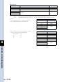
3. Direct connection by emulated serialization on parallel DIO
The robot controller's parallel input data can be transferred to the serial output data regardless of the robot
program. Likewise, the robot controller's serial input data can be transferred to the parallel output data.
By using this function, a sensor or relay connected to the parallel I/O of the robot controller can be used like
a device connected to the EtherNet/IP master module.
Direct connection by emulated serialization
EtherNet/IP master module
Robot controller
Output
SI
DO
Relay, valve, etc.
Input
SO
DI
Sensor, etc.
3
Parallel I/O connection
EtherNet/IP connection
23301-S6-00
NOTE
When the directly connected and set output port is used with the program, the bit information may not become
the intended value. Do not use the directly connected and set output port with the program.
3.1
Emulated serialization setting on parallel DIO
The relation of the parallel port and serial port that can be connected is shown below.
Input device such as sensor
Output device such as valve
DI port → SO port
DO port ← SI port
DI2()
SO2()
DO2()
SI2()
DI3()
SO3()
DO3()
SI3()
DI4()
SO4()
DO4()
SI4()
DI5()
SO5()
DO5()
SI5()
■ ■ Operation
Press the
(SIO) key in the "SYSTEM >OPTION" mode.
The setting screen will appear that is necessary to make the emulated serialization setting on parallel DIO.
SIO setting screen
SYSTEM>OPTION>SIO V10.50
−−−−−−−−−−−−−−−−−−−−−−−−−−−−−−−−−−−−−−−−
1.Direct SI2() −> DO2() NO 2.Direct SI3() −> DO3() NO
3.Direct SI4() −> DO4() NO
4.Direct SI5() −> DO5() NO
5.Direct SO2() <− DI2() NO
EDIT JUMP
24301-S6-00
Valid keys and submenu functions in this mode are as follows.
Valid keys
Menu
/
n
Function
Selects SIO parameters.
EDIT
Sets SIO parameters.
JUMP
Jumps to specified SIO parameter.
NOTE
When the port specified by SIO is identical with the port used by the program, the output results might be
inaccurate.
3-5
Communication
n
111 Direct connection from SI n ( ) to DO n ( )
Serial port input can be directly connected to the parallel port output. The relation of the parallel port and serial port
that can be connected is as follows.
Output device such as sensor
DO port ← SI port
3
n
DO2()
SI2()
DO3()
SI3()
DO4()
SI4()
DO5()
SI5()
NOTE
When the port specified by SIO is identical with the port used by the program, the output results might be
inaccurate.
■ ■ Operation
Communication
1 Select "SIO".
Select "SYSTEM > OPTION > SIO".
The SIO setting screen will appear.
2 Select a SI port.
Use the
or
key (cursor up or down
key) to move the cursor to a desired SI port
(from "1. Direct SI2() -> DO2()" to "4. Direct
SI5() -> DO5()") and press the
(EDIT)
key.
3 Set the direct connection.
Press the
Step 3
(SET) key to make the direct
connection valid.
Press the
(NO) key to make the direct
connection invalid.
24302-S6-00
4 Exit the setting.
Press the
key to exit the setting.
Subsequently, to set other item, use the
or
key (cursor up or down key) to select
other SI port.
3-6
Setting SI port direct connection
SYSTEM>OPTION>SIO V10.50
−−−−−−−−−−−−−−−−−−−−−−−−−−−−−−−−−−−−−−−−
1.Direct SI2() −> DO2() NO 2.Direct SI3() −> DO3() NO
3.Direct SI4() −> DO4() NO
4.Direct SI5() −> DO5() NO
5.Direct SO2() <− DI2() NO
SET NO
222 Direct connection from DI n ( ) to SDO n ( )
Parallel port input can be directly connected to the serial port output. The relation of the parallel port and serial port that
can be connected is as follows.
Input device such as valve
DI port → SO port
n
DI2()
SO2()
DI3()
SO3()
DI4()
SO4()
DI5()
SO5()
NOTE
When the port specified by SIO is identical with the port used by the program, the output results might be
inaccurate.
3
■ ■ Operation
Communication
1 Select "SIO".
Select "SYSTEM > OPTION > SIO".
The SIO setting screen will appear.
2 Select a DI port.
Use the
or
key (cursor up or down
key) to move the cursor to a desired DI port
(from "5. Direct SO2() <- DI2()" to "8. Direct
SO5() <- DI5()") and press the
(EDIT)
key.
Step 3
3 Set the direct connection.
Press the
(SET) key to make the direct
connection valid.
Press the
(NO) key to make the direct
connection invalid.
24303-S6-00
4 Exit the setting.
Press the
Setting DI port direct connection
SYSTEM>OPTION>SIO V10.50
−−−−−−−−−−−−−−−−−−−−−−−−−−−−−−−−−−−−−−−−
4.Direct SI5() −> DO5() NO
5.Direct SO2() <− DI2() NO 6.Direct SO3() <− DI3() NO
7.Direct SO4() <− DI4() NO
8.Direct SO5() <− DI5() NO
SET NO
key to exit the setting.
Subsequently, to set other item, use the
or
key (cursor up or down key) to select
other DI port.
3-7
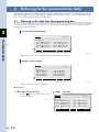
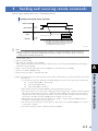
4. Referring to the communication data
The ON/OFF information exchanged with the master module can be referred to with the RPB. Note that the
RPB display update interval is longer than the EtherNet/IP data update interval. So, if the ON/OFF interval
is short, accurate information may not be displayed.
4.1
Referring to the data from the programming box
The data exchanged with the master module can be referred to with the RPB. The reference unit is the robot
controller input/output port No.
3
Communication screen with RPB
Communication
SYSTEM V10.50
−−−−−−−−−−−−−−−−−−−−−−−−−−−−−−−−−−−−−−−−
SI monitor
SI0()=&B00000111 SI4()=&B11000000
SI1()=&B00001111 SI5()=&B00101000
SI2()=&B00010001 SI6()=&B00000111
SI3()=&B00000100 SI7()=&B00000000
PARAM CUM OPTION INIT DIGNOS 24304-S6-00
* &Bxxxxxxx corresponds to the 0th bit to 7th bit from the right to the left.
Reference screen from RPB
SYSTEM V10.50
−−−−−−−−−−−−−−−−−−−−−−−−−−−−−−−−−−−−−−−−
SIW monitor
SIW(0)=&H0132 SIW(4)=&H0000
SIW(1)=&H0001 SIW(5)=&H0000
SIW(2)=&H8000 SIW(6)=&HFFFF
SIW(3)=&H0000 SIW(7)=&H0000
PARAM CUM OPTION INIT DIGNOS
24305-S6-00
* &Hxxxx expresses a hexadecimal value.
■ ■ Operation
1 Display the DI monitor.
Press the
Step 1
key on the RPB. The DI monitor
screen will appear.
24306-S6-00
3-8
DI monitor
SYSTEM V10.50
−−−−−−−−−−−−−−−−−−−−−−−−−−−−−−−−−−−−−−−−
DI monitor
DI0()=&B00000111 DI4()=&B11000000
DI1()=&B00001111 DI5()=&B00101000
DI2()=&B00010001 DI6()=&B00000111
DI3()=&B00000100 DI7()=&B00000000
PARAM CUM OPTION INIT DIGNOS
2 Display the input/output port
status.
Press the
key on the RPB until the SI
input ports 0 to 7 are displayed.
(See the figure shown on the right.)
24207-S6-00
The input/output port status is displayed in
the order shown below each time the
key is pressed from this status.
SI input ports 10 to 15
↓
Unused.
↓
SO input ports 0 to 7
↓
SO input ports 10 to 15
↓
Unused.
↓
SIW input ports 0 to 7
↓
SIW input ports 8 to 15
↓
SOW output ports 0 to 7
↓
SOW output ports 8 to 15
Step 2
Displaying SI input ports 0 to 7
SYSTEM V10.50
−−−−−−−−−−−−−−−−−−−−−−−−−−−−−−−−−−−−−−−−
SI monitor
SI0()=&B00000111 SI4()=&B11000000
SI1()=&B00001111 SI5()=&B00101000
SI2()=&B00010001 SI6()=&B00000111
SI3()=&B00000100 SI7()=&B00000000
PARAM CUM OPTION INIT DIGNOS
3
Communication
3 Exit the DI monitor.
After you have checked the input/output
port status, press the
key to exit the DI
monitor.
3-9
Chapter 4 Troubleshooting
Contents
1. Check items before starting up the EtherNet/IP system 4-1
2. Meanings of LEDs on EtherNet/IP compatible module
4-2
3. Troubleshooting
4-3
3.1
Robot controller front panel LED confirmation
4-3
3.2
Programming box error display confirmation
4-3
3.3 EtherNet/IP compatible module LED confirmation
4-4
3.4 Confirmation from master module
4-4
4. Error messages relating to EtherNet/IP
4-5
1. Check items before starting up the EtherNet/IP system
Check the following items before starting up the EtherNet/IP system.
Check item
1
Is the EtherNet/IP compatible module connected securely?
(Refer to section 1 in Chapter 2.)
2
Is the robot controller set to the EtherNet/IP system specifications?
(Refer to section 2 in Chapter 2.)
3
Are the IP address, subnet mask, and gateway of the EtherNet/IP compatible module are set correctly?
(Refer to section 3 in Chapter 2.)
4
Are the ferrite cores connected to the power input cable to the robot controller?
(Refer to section 4 in Chapter 2.)
5
Is the EtherNet/IP system cable connected to the EtherNet/IP compatible module securely?
(Refer to section 5 in Chapter 2.)
6
Was the line test from the master module correct?
(Refer to the user’s manual for master module.)
n
Check
4-1
4
Troubleshooting
NOTE
In the RCX240, the dedicated input of STD. DIO provided on the controller will be disabled except for the
interlock signal (DI11). When the external 24V monitor control of the system parameters is set invalid, the interlock
signal (DI11) will also be disabled.
2. Meanings of LEDs on EtherNet/IP compatible module
Status indicators
1. Activity
1
3
3. Link
2. Network Status
2
4
4. Module Status
23401-S6-00
The LEDs on the EtherNet/IP compatible module express the following statuses.
Use these for the confirmation work if an error occurs.
111 Activity
4
: Flashing green during packet communication.
222 Network Status :
Status
Description
OFF
Power is OFF or no IP address is found.
Troubleshooting
Lit in green
Detects the online and connects other unit.
Flashing green
Detects the online, but does not connect other unit.
Lit in red
Detects serious error, such as IP address duplication.
Flashing red
Time-out occurs during connection with other unit.
Flashing green/red
Performing the self-test (only when the power is turned ON).
333 Link
: Lit in green when the link is detected.
444 Module Status
:
Status
OFF
Lit in green
Flashing green
Lit in red
Flashing red
Flashing green/red
4-2
Description
Power is OFF.
Connection with the master is correct.
Connection with the master is not established.
Recoverable minor error is detected.
Unrecoverable error is detected.
Performing the self-test (only when the power is turned ON).
3. Troubleshooting
3.1
Robot controller front panel LED confirmation
■ ■ Confirmation item 1
Confirmation
contents
• The "PWR" LED is OFF.
Cause
• The power is not supplied to the robot controller.
Corrective
measures
• M easure the voltage at the AC power input terminal of the power connector with a multi-meter to check
that the operating power voltage is supplied.
MEMO
For details about the operating power voltage for the robot controller, refer to the user’s manual for robot
controller.
■ ■ Confirmation item 2
• The "ERR" LED is ON.
• The robot controller is in the emergency stop state.
Cause
• A serious error has occurred in the robot controller.
Corrective
measures
• C heck the error message displayed on the programming box.
• Take corrective measures while referring to the troubleshooting stated in the user’s manual for robot
controller.
MEMO
For details about error contents, refer to the user’s manual for robot controller.
3.2
RPB (programming box) error display confirmation
■ ■ Confirmation item
Confirmation
contents
• Check the error message displayed on the RPB.
Cause
• An error has occurred in the robot controller.
Corrective
measures
• C heck the error message displayed on the RPB.
• Check the error history with the RPB. At this time, check the error history with the RPB in the "SYSTEM>
DIAGNOS > HISTORY" mode.
• Take corrective measures while referring to the troubleshooting stated in the user’s manual for robot
controller.
MEMO
For details about error contents, see the user’s manual for robot controller.
4-3
Troubleshooting
Confirmation
contents
4
3.3
EtherNet/IP compatible module LED confirmation
■ ■ Confirmation item
4
Confirmation
contents
• Check that the LED indication on the EtherNet/IP compatible module is not "ACT: Flashing green", "Link:
Lit in green", "MS: Lit in green", and "NS: Lit in green".
Cause
• An error has occurred in the EtherNet/IP system connection.
• For details about LED indication meanings, refer to the table stated in "2. Meanings of LEDs on
EtherNet/IP compatible module" of Chapter 4 in this guide.
Corrective
measures
• C heck whether the LAN cable is not connected or connected incorrectly, and whether or not the straight
or cross cable does not meet the specifications.
• Check whether the LAN cable is run close to the main circuit or power cable or whether or not it is
bundled.
• Check that the ferrite core is connected to the power supply cable of the robot controller.
• Check the TCP/IP setting of the EtherNet/IP compatible module.
• Check that the master module is operating correctly.
3.4
Confirmation from master module
■ ■ Confirmation item
Troubleshooting
Confirmation
contents
• Use the connection setting function or connection check function of the master module to check that the
robot controller is connected to the EtherNet/IP system correctly.
Cause
• The signal has noise.
• The cable is broken.
• The IP address setting is incorrect.
Corrective
measures
• R eplace the cable.
• Change the cable running route to lay it away from the noise source, such as power cable.
• Check the IP address setting.
MEMO
For details about connection setting function, refer to the user’s manual for master module.
Furthermore, for details about IP address and other settings, contact the system administrator.
4-4
4. Error messages relating to EtherNet/IP
This section describes error messages relating to EtherNet/IP compatible modules. For other messages, refer
to the user's manual for robot controller.
If an error occurs, relevant error message appears on the message line (2nd line) of the RPB screen.
12.1 : Emg.stop on
Code
: &H0C01
Meaning/Cause
Action
a.RPB emergency stop button was pressed.
b.Emergency stop terminals in the SAFETY connector are open (emergency stop state).
c.RPB or terminator is not connected to the RPB connector.
d.SAFETY connector is not connected.
e.SI(00) is not ON.
f. Error in the connection to the EtherNet/IP system.
1.Release the RPB emergency stop button.
2.Close the emergency stop terminals in the SAFETY connector.
3.Connect the RPB or terminator to the RPB connector.
4.Attach the SAFETY connector.
5.Set SI(00) to ON.
6.Correct the connection to the EtherNet/IP system.
4
Code
: &H0C02
Meaning/Cause
Action
a.Program was executed or moving of axis attempted with the interlock signal still input.
b.Interlock signal turned ON during execution of program or axis movement.
c.DC 24V is supplied to the STD.DIO connector and DI(11) is not turned ON while using the RCX240.
d.SI(11) is not ON.
e.Error in the connection to the EtherNet/IP system.
1.Cancel the interlock signal, and execute the program or move the axis.
2.Set DI(11) on the STD.DIO connector to ON. (RCX240)
3.Set SI(11) to ON.
4.When not using STD.DIO, disable (invalid) the "Watch on STD.DO DC24V" parameter in the SYSTEM mode. (RCX240)
5.Correct the connection to the EtherNet/IP system.
12.51 : EtherNet/IP link error
Code
: &H0C33
Meaning/Cause
Action
a.Error in the EtherNet/IP option board.
1.Contact our company.
12.70 : Incorrect option setting
Code
: &H0C46
Meaning/Cause
a.Error in the DIP switch setting on the option unit.
b.Mismatched option units have been installed.
c.Cannot identify the installed option unit.
Action
1.Check the DIP switch settings on the option unit.
2.Install the correct option units.
3.Replace the option unit.
21.16 : System error (EherNet/IP)
Code
: &H1510
Meaning/Cause
a.Error in the software.
Action
1.Contact our company.
4-5
Troubleshooting
12.2 : Interlock on
Chapter 5 Specifications
Contents
1. Profile
5-1
2. Details of input/output signals
5-3
3. Dedicated input/output signal timing chart
5-6
3.1 Servo ON and emergency stop
5-6
3.2 AUTO mode changeover, program reset and program execution
5-7
3.3 Stopping with program interlock
5-8
4. EtherNet/IP compatible module specifications
5. EtherNet/IP specifications
5-9
5-10
1. Profile
■ ■ Bit input/output
Slave → Master
Address
m+32
m+33
Bit
Signal name
Master → Slave
Address
Bit
Signal name
0
SO(00)
Emergency stop input status output
0
SI(00)
Emergency stop input
1
SO(01)
CPU_OK status output
1
SI(01)
Servo ON input
2
SO(02)
Servo ON status output
2
SI(02)
Service mode input
3
SO(03)
Alarm status output
3
n+32
4
Reserved.
5
Reserved.
5
6
Reserved.
6
7
Reserved.
7
Reserved.
4
Reserved.
SI(05)
I/O command execution trigger input
Reserved.
Reserved.
0
SO(10)
AUTO mode status output
0
SI(10)
Sequence control input
1
SO(11)
Return-to-origin complete status
output
1
SI(11)
Interlock input
2
SO(12)
Sequence program execution status
output
2
SI(12)
Start input
3
SO(13)
Robot program execution status
output
3
SI(13)
AUTO mode input
4
SO(14)
Program reset status output
4
SI(14)
Return-to-origin input
Reserved.
5
SI(15)
Program reset input
5
n+33
5
SO(16)
I/O command execution judgment
output
6
SI(16)
MANUAL mode input
7
SO(17)
Output during I/O command
execution
7
SI(17)
Absolute reset / Return-to-origin
input *1
m+34
0~7
SO(20)
~
SO(27)
General-purpose output
n+34
0~7
SI(20)
~
SI(27)
General-purpose input
m+35
0~7
SO(30)
~
SO(37)
General-purpose output
n+35
0~7
SI(30)
~
SI(37)
General-purpose input
m+36
0~7
SO(40)
~
SO(47)
General-purpose output
n+36
0~7
SI(40)
~
SI(47)
General-purpose input
m+37
0~7
SO(50)
~
SO(57)
General-purpose output
n+37
0~7
SI(50)
~
SI(57)
General-purpose input
m+38
0~7
SO(60)
~
SO(67)
General-purpose output
n+38
0~7
SI(60)
~
SI(67)
General-purpose input
m+39
0~7
SO(70)
~
SO(77)
General-purpose output
n+39
0~7
SI(70)
~
SI(77)
General-purpose input
m+40
0~7
SO(100)
~
General-purpose output
SO(107)
n+40
0~7
SI(100)
~
SI(107)
General-purpose input
m+41
0~7
SO(110)
~
General-purpose output
SO(117)
n+41
0~7
SI(110)
~
SI(117)
General-purpose input
m+42
0~7
SO(120)
~
General-purpose output
SO(127)
n+42
0~7
SI(120)
~
SI(127)
General-purpose input
m+43
0~7
SO(130)
~
General-purpose output
SO(137)
n+43
0~7
SI(130)
~
SI(137)
General-purpose input
m+44
0~7
SO(140)
~
General-purpose output
SO(147)
n+44
0~7
SI(140)
~
SI(147)
General-purpose input
m+45
0~7
SO(150)
~
General-purpose output
SO(157)
n+45
0~7
SI(150)
~
SI(157)
General-purpose input
(continued to next page)
5-1
Specifications
6
Slave → Master
Address
Bit
m+46
0~7
Reserved.
m+47
0~7
Reserved.
Master → Slave
Signal name
Address
Bit
n+46
0~7
Reserved.
Signal name
n+47
0~7
Reserved.
m: Start address of the input area assigned to the master module
n : Start address of the output area assigned to the master module
*1:Used for "absolute reset" or "absolute reset / return-to-origin" depending on the parameter (DI17 mode) setting.
■ ■ Word input/output
Slave → Master
Address
Address
Name
m
SOW(0)
Dedicated output
n
SIW(0)
Dedicated input
m+2
SOW(1)
Dedicated output
n+2
SIW(1)
Dedicated input
SOW(2)
General-purpose output
n+4
SIW(2)
General-purpose input
m+4
m+6
m+8
m+10
m+12
m+14
m+16
m+18
5
Master → Slave
Name
m+20
m+22
m+24
m+26
Specifications
m+28
m+30
SOD(2)
SOD(4)
SOD(6)
SOD(8)
SOD(10)
SOD(12)
SOD(14)
SOW(3)
General-purpose output
n+6
SOW(4)
General-purpose output
n+8
SOW(5)
General-purpose output
n+10
SOW(6)
General-purpose output
n+12
SOW(7)
General-purpose output
n+14
SOW(8)
General-purpose output
n+16
SOW(9)
General-purpose output
n+18
SOW(10)
General-purpose output
n+20
SOW(11)
General-purpose output
n+22
SOW(12)
General-purpose output
n+24
SOW(13)
General-purpose output
n+26
SOW(14)
General-purpose output
n+28
SOW(15)
General-purpose output
n+30
SID(2)
SID(4)
SID(6)
SID(8)
SID(10)
SID(12)
SID(14)
SIW(3)
General-purpose input
SIW(4)
General-purpose input
SIW(5)
General-purpose input
SIW(6)
General-purpose input
SIW(7)
General-purpose input
SIW(8)
General-purpose input
SIW(9)
General-purpose input
SIW(10)
General-purpose input
SIW(11)
General-purpose input
SIW(12)
General-purpose input
SIW(13)
General-purpose input
SIW(14)
General-purpose input
SIW(15)
General-purpose input
m: Start address of the input area assigned to the master module
n : Start address of the output area assigned to the master module
5-2
2. Details of input/output signals
■ ■ Bit output
Address
Signal name
Description
SO(00)
Emergency stop input status output
Turns ON when the robot controller is in the emergency stop state.
(m+32)1
SO(01)
CPU_OK status output
Turns ON when the robot controller is in the normal state.
(m+32)2
SO(02)
Servo ON status output
Turns ON when the motor power of the robot controller is ON.
(m+32)3
SO(03)
Alarm status output
Turns ON when the robot controller is in any of the following states.
• The controller is in the serious error state.
• The emergency stop input is turned OFF.
(m+33)0
SO(10)
AUTO mode status output
Turns ON when the AUTO mode is selected.
Turns OFF when other mode is selected.
(m+33)1
SO(11)
Return-to-origin complete status
output
Turns ON when the robot has completed the return-to-origin.
(m+33)2
SO(12)
Sequence program execution status
Turns ON while the sequence program is being executed.
output
(m+33)3
SO(13)
Robot program execution status
output
Turns ON while the robot program is being executed.
(m+33)4
SO(14)
Program reset status output
Turns ON when the robot program has been reset.
Turns OFF when the robot program starts.
(m+33)6
SO(16)
I/O command execution judgment
output
Turns OFF while the I/O command is being executed.
After the I/O command has been executed, turns ON if normal and
stays OFF if abnormal.
(m+33)7
SO(17)
Output during I/O command
execution
Turns ON while the I/O command is being executed.
(m+34)0
~
(m+34)7
SO(20)
~
SO(27)
General-purpose output
~
(m+44)0
~
(m+44)7
~
SO(150)
~
SO(157)
~
General-purpose output turns ON/OFF when the value is assigned
to the SO port, or SET/RESET command or OUT command is
executed.
General-purpose output
m: Start address of the input area assigned to the master module
n
NOTE
When the area check output function is used, the area check outputs can be assigned to the general-purpose
outputs SO(20) to SO(157).
5-3
5
Specifications
(m+32)0
■ ■ Bit input
Address
(n+32)0
(n+32)1
5
Signal name
SI(00)
SI(01)
Description
Emergency stop input
Turn OFF to put the controller in the emergency stop state.
Keeps turned ON during normal operation.
Servo ON input
Turn ON to cancel the emergency stop state and put the robot
servomotor in the ON state.
The servo ON is executed when this signal is switched from OFF to
ON.
It is necessary that the emergency stop input [SI(00)] is in the ON
state and all emergency stop states (emergency stop terminal in the
SAFETY connector, etc.) on the robot controller are cancelled.
Turn OFF to put the controller in the SERVICE mode.
Keeps turned ON during normal operation.
(This signal is valid only when the SAFE mode is set.)
(When the SAFE mode is set and the controller is in the SERVICE
mode, the dedicated input may become invalid depending on the
SERVICE mode setting.)
(n+32)2
SI(02)
Service mode input
(n+32)5
SI(05)
Switch this signal from OFF to ON to execute the I/O command.
I/O command execution trigger input Note that this signal must be turned ON when the I/O command is
set for the general-purpose input.
(n+33)0
SI(10)
Sequence control input
Turn ON to execute the sequence program in the robot controller.
The sequence program is executed when this signal is in the ON
state.
(n+33)1
SI(11)
Interlock input
Turn OFF to stop the robot program currently being executed.
To execute the program, keep this signal turned ON.
Specifications
(n+33)2
SI(12)
Start input
Turn ON to execute the robot program.
The robot program is executed when this signal is switched from
OFF to ON.
It is necessary that the robot controller is in the AUTO mode.
(n+33)3
SI(13)
AUTO mode input
Turn ON to select the AUTO mode.
The mode transits to the AUTO mode when this signal is switched
from OFF to ON.
(n+33)4
SI(14)
Return-to-origin input
Turn ON to perform the return-to-origin of the incremental type axis
or semi-absolute type axis.
When this signal is switched from OFF to ON, the incremental type
axis performs the return-to-origin and the semi-absolute type axis
performs the absolute search operation.
This signal is intended for axes whose return-to-origin method is
the sensor or stroke end method.
It is necessary that the robot controller is in the MANUAL mode.
(n+33)5
SI(15)
Program reset input
Turn ON to reset the robot program.
The program is reset when this signal is switched from OFF to ON.
It is necessary that the robot controller is in the AUTO mode.
(n+33)6
SI(16)
MANUAL mode input
Turn ON to select the MANUAL mode.
The mode transits to the MANUAL mode when this signal is
switched from OFF to ON.
Used for "absolute reset" or "absolute reset / return-to-origin"
depending on the parameter (DI17 mode) setting.
(n+33)7
5-4
SI(17)
Absolute reset /
Return-to-origin input
• When set at "ABS" (absolute reset);
Turn ON to perform the absolute reset of the robot.
The absolute reset is executed when this signal is switched
from OFF to ON. The axis whose return-to-origin method is the
mark method does not perform the absolute reset. Additionally,
if the axis whose return-to-origin method is the mark method
does not complete the return-to-origin, the absolute reset is not
executed using the dedicated input.
It is necessary that the robot controller is in the MANUAL
mode.
• When set at "ABS/ORG"(absolute reset/return-to-origin);
Only the absolute type axis performs the absolute reset. The
absolute reset is executed when this signal is switched from
OFF to ON.
When this signal is switched from OFF to ON, the incremental
type axis performs the return-to-origin and the semi-absolute
type axis performs the absolute search operation.
When the absolute type axis, incremental type axis, and
semi-absolute type axis are mixed, the incremental type axis
and semi-absolute type axis perform the return-to-origin after
the absolute type axis has performed the absolute reset.
Address
Signal name
(n+34)0
~
(n+34)7
SI(20)
~
SI(27)
General-purpose input
(n+35)0
~
(n+35)7
SI(30)
~
SI(37)
General-purpose input
~
(n+44)0
~
(n+44)7
~
SI(150)
~
SI(157)
Description
Refers to the SI port value, executes the WAIT command, and uses
the ON/OFF state of the general-purpose input.
~
General-purpose input
n : Start address of the output area assigned to the master module
n
NOTE
• When the RCX141 or RCX221 is changed to the RCX240 and SI(17) needs to be used for the return-to-origin input, SI(17) is used for "absolute reset/return-to-origin".
• When the RCX240 is used with a robot whose axis configuration includes the absolute type, incremental type, and semi-absolute type axes and SI(17) is used for "absolute reset/return-to-origin", the absolute reset is performed for the absolute reset type axis each time the return-to-origin is performed for the incremental type or semi-absolute type axis.
So, when the robot axis configuration includes the absolute type, incremental type, and semi-absolute type axes, it is recommended to perform the absolute reset with SI(17) and return-to-origin with SI(14).
• The return-to-origin input and absolute reset input can also be executed in the AUTO mode by changing the execution level. For details, refer to the user’s manual for controller.
■ ■ Word input
Address
Name
SIW(0)
SIW(1)
n+4
n+6
n+8
n+10
n+12
n+14
n+16
n+18
n+20
n+22
n+24
n+26
n+28
n+30
SID(2)
SID(4)
SID(6)
SID(8)
SID(10)
SID(12)
SID(14)
Dedicated input
Used as the remote command area.
Used as the command data area of the remote command.
SIW(2)
SIW(3)
SIW(4)
SIW(5)
SIW(6)
SIW(7)
SIW(8)
SIW(9)
Used to input the word or double word data from the SIW or SID
General-purpose input port.
Or, used as the command data area of the remote command.
SIW(10)
SIW(11)
SIW(12)
SIW(13)
SIW(14)
SIW(15)
n : Start address of the output area assigned to the master module
■ ■ Word output
Address
Name
m
SOW(0)
m+2
SOW(1)
m+4
SOW(2)
m+6
m+8
m+10
m+12
m+14
m+16
m+18
m+20
m+22
m+24
m+26
m+28
m+30
SOD(2)
SOD(4)
SOD(6)
SOD(8)
SOD(10)
SOD(12)
SOD(14)
Dedicated output
Description
Used as the status area of the remote command.
Used as the error code area of the remote command.
SOW(3)
SOW(4)
SOW(5)
SOW(6)
SOW(7)
SOW(8)
General-purpose
SOW(9)
output
5
Used to output the word or double word data from the SOW or
SOD port.
Or, used as the response area of the remote command.
SOW(10)
SOW(11)
SOW(12)
SOW(13)
SOW(14)
SOW(15)
m: Start address of the input area assigned to the master module
5-5
Specifications
n
n+2
Description
3. Dedicated input/output signal timing char t
3.1
Ser vo ON and emergency stop
Servo ON and emergency stop
(m+32)0:SO(00)
Emergency stop input
status output
(m+32)1:SO(01)
CPU_OK status output
(m+32)2:SO(02)
Servo ON status output
(m+32)3:SO(03)
Alarm status output
(n+32)0:SI(00)
Emergency stop input
5
(n+32)1:SI(01)
Servo ON input
on
off
on
off
on
off
on
off
on
off
on
off
a)
b) c)
d) e)
f) g)
h) i)
j)
k)
23501-S6-00
Specifications
c
CAUTION
• Provide an interval of 100ms or more when turning the dedicated input from the master module to the controller
ON and OFF. If the interval is too short, the dedicated input may not be recognized. (This also applies to the interval for the same dedicated inputs or different dedicated inputs.)
• Use this also if there is a dedicated output in response to the dedicated input from the master module to the controller.
■ ■ Initial ser vo ON process after power ON
a)Servo ON input ON is input
b)If not in the emergency stop state, output servo ON status ON is output
c)After confirming that servo ON status output is ON, servo ON input OFF is input
■ ■ Shift to emergency stop
d)Emergency stop input OFF is input
e)Emergency stop input status ON and alarm status output ON are output
Servo ON status output OFF is output
■ ■ Ser vo ON process from emergency stop status
f) Emergency stop input ON is input
g)Emergency stop input status output OFF is output
h)Servo ON input ON is input
i) Alarm status output OFF is output
j) Servo ON status output ON is output
k)After confirming that servo ON status output is ON, servo ON input OFF is input
* The servo is OFF when the controller power is turned ON.
* When SAFE mode is enabled, dedicated inputs other than SI (00) and SI (11) might be disabled depending on service
mode parameter setting unless service mode input signal is set to ON with SI (02) in the EtherNet/IP system.
5-6
3.2
AUTO mode changeover, program reset and program execution
AUTO mode changeover, program reset and program execution
on
(m+33)0:SO(10)
AUTO mode status
output
off
on
(m+33)1:SO(11)
Return-to-origin complete
status output
off
on
(m+33)3:SO(13)
Robot program execution
status output
off
on
(m+33)4:SO(14)
Program reset status output
off
on
(n+33)1:SI(11)
Interlock input
(n+33)2:SI(12)
Robot program start input
(n+33)3:SI(13)
AUTO mode input
(n+33)5:SI(15)
Program reset input
off
on
off
on
5
off
on
off
b)
c)
d)
100ms or more
e)
f)
g) h)
i)
100ms or more
23502-S6-00
c
CAUTION
• Provide an interval of 100ms or more when turning the dedicated input from the master module to the controller
ON and OFF. If the interval is too short, the dedicated input may not be recognized. (This also applies to the interval for the same dedicated inputs or different dedicated inputs.)
• Use this also if there is a dedicated output in response to the dedicated input from the master module to the controller.
■ ■ AUTO mode changeover process
a)AUTO mode input ON is input
b)AUTO mode status output ON is output
c)After confirming that the AUTO mode status output is ON, the AUTO mode input OFF is input
■ ■ Program reset process
d)Program reset input ON is input
e)Program reset status output ON is output
f) After confirming that the program reset status output is ON, the program reset input OFF is input
■ ■ Program execution process
g)Robot program start input ON is input
h)Program reset status output OFF is output
Robot program execution status output ON is output
i) After confirming that the robot program execution status output is ON, the robot program start input OFF is input
* The program cannot be executed if the emergency stop input and interlock input are OFF.
* If the return-to-origin complete status output is not ON, execution of the program may not be possible depending on
the execution level setting value.
* When SAFE mode is enabled, dedicated inputs other than SI (00) and SI (11) might be disabled depending on service
mode parameter setting unless service mode input signal is set to ON with SI (02) in the EtherNet/IP system.
5-7
Specifications
a)
3.3
Stopping with program interlock
Stopping with program interlock
on
(m+33)0:SO(10)
AUTO mode status
output
(m+33)1:SO(11)
Return-to-origin complete
status output
(m+33)3:SO(13)
Robot program execution
status output
(n+33)1:SI(11)
Interlock input
off
on
off
on
off
on
off
(n+33)2:SI(12)
Robot program start
input
on
off
a)
b)
c)
d) e)
5
f)
g) h)
i)
100ms or more
23503-S6-00
Specifications
c
CAUTION
• Provide an interval of 100ms or more when turning the dedicated input from the master module to the controller
ON and OFF. If the interval is too short, the dedicated input may not be recognized. (This also applies to the interval for the same dedicated inputs or different dedicated inputs.)
• Use this also if there is a dedicated output in response to the dedicated input from the master module to the controller.
■ ■ Program execution process
a)Robot program start input ON is input
b)Robot program execution status output ON is output
c)After confirming that the robot program execution status output is ON, the start input OFF is input
■ ■ Program stop process using interlock input
d)Interlock input OFF is input
e)Robot program execution status output OFF is output
■ ■ Program execution after stopping program with interlock input
f) Interlock input ON is input
g)Robot program start input ON is input
h)Robot program execution status output ON is output
i) After confirming that the robot program execution status output is ON, the start input OFF is input
* The program also stops when emergency stop input OFF is input. At this point, emergency stop input status ON and
alarm status output ON are output, and servo ON status output OFF is output. To re-execute the program, servo ON
process is required.
* When SAFE mode is enabled, dedicated inputs other than SI (00) and SI (11) might be disabled depending on service
mode parameter setting unless service mode input signal is set to ON with SI (02) in the EtherNet/IP system.
5-8
4. EtherNet/IP compatible module specifications
Model
EtherNet/IP compatible module
Spec. Item
Controller model
RCX240
Software version
V10.50 or higher
Network specifications
Conforms to Ethernet (IEEE 802.3).
Applicable EtherNet/IP specifications
Volume 1 : Common Industrial protocol (CIPTM) Edition 3.8
Volume 2 : EtherNet/IP Adaptation Edition 1.9
Device type
Generic Device (Device No. 43)
Data size
48 bytes each for input/output
Transmission speed
10 Mbps/100 Mbps
Connector specifications
RJ-45 connector (8-pole modular connector) 1 port
Cable specifications
Refer to “4.1. LAN cable” in Chapter 2 of this guide.
Max. cable length
100 m
EtherNet/IP input/output points *1
Input
(48 bytes in total)
Output
(48 bytes in total)
byte 0-3
byte 4-31
Dedicated word input
: 2 words
General purpose word input : 14 words
byte 32-33
byte 34-47
Dedicated bit input
General-purpose bit input
byte 0-3
byte 4-31
Dedicated word output
: 2 words
General-purpose word output : 14 words
byte 32-33
byte 34-47
Dedicated bit output
General-purpose bit output
: 16 points
: 96 points
5
: 16 points
: 96 points
Regardless of the robot program, the master module and up to four ports can be controlled
using the emulated serialization function.
Settings, such as IP address
The settings are made with the programming box (RPB).
Monitor LEDs
Activity, Network Status, Link, Module Status
CPU BOARD ASSY
KX0-M4210-2XX (Refer to “3. Installing into the robot controller” in Chapter 1 of this
guide.)
*1:Controller’s I/O update intervals are 10 ms at shortest, but actual I/O update intervals may vary depending on the update time
for the master station.
c
CAUTION
• For the names and contents of the word and bit input/output signals, refer to the tables shown in the sections, "Profile" and "Details of input/output signals".
• The specifications and appearance are subject to change without prior notice due to continual improvement.
5-9
Specifications
Parallel external input
5. EtherNet/IP specifications
■ ■ General data
Applicable EtherNet/IP specifications
Volume 1 : Common Industrial protocol (CIPTM) Edition 3.8
Volume 2 : EtherNet/IP Adaptation Edition 1.9
Vendor name
YAMAHA MOTOR CO.,LTD. (Vendor ID 636)
Device type
Generic Device (Device No. 43)
Product code
5
Product revision
1.1
5
Specifications
5-10
Chapter 6 Appendix
Contents
1. Definitions of terms
6-1
2. EDS files
6-4
1. Definitions of terms
■ ■ EtherNet/IP (Ethernet/Industrial Protocol)
This EtherNet/IP is a communication protocol that CIP (Common Industrial Protocol) is mounted on the Ethernet and
TCP/IP.
The EtherNet/IP is jointly controlled by ODVA (Open DeviceNet Vendor Association) and CI (ContorolNet International).
■ ■ CIP (Ethernet/Industrial Protocol)
This CIP is a protocol for the application layer that does not depend on the physical layer used for the EtherNet/IP or
DeviceNet.
The CIP provides the standard object that can access to data and includes functions necessary for industrial network
units.
■ ■ TCP/IP (Transmission Control Protocol / Internet Protocol)
This TCP/IP is a standard protocol for the Internet communication. The TCP/IP is a generic name of multiple protocol
groups that use the TCP and IP protocols as a core. All computers and personal computers that can access to the Internet
use the TCP/IP protocol.
■ ■ Ethernet
Simply put, this Ethernet is a kind of standard for the hardware related to the network system.
The Ethernet is a network that was invented by Xerox in the U.S.A. in the early 1970s. Presently, the Ethernet is nationalstandardized as IEE802.3. The specifications are classified into 10BASE-2, 10BASE-5, and 10BASE-T by the transmission
cable type. The maximum cable length or the maximum number of connections may vary depending on the
specifications. The EtherNet/IP compatible module for the RCX240 uses the 10BASE-T specifications.
Protocols generally used for the Ethernet are NetBEUI and IPX/SPX in addition to the TCP/IP protocol.
Additionally, the features of the Ethernet are that the CSMA/CD method is used for the data transmission method.
This CSMA/CD is a signal transmission method that the data transmission method called "CSMA" is combined with the
transmission troubleshooting method called "CD".
Since the CSMA commonly uses multiple units connected to the network only with one transmission cable, it checks the
network working status to confirm the transmission ready status before transmitting the data.
The CD waits for randomly determined time, and then transmits the data again if data collision occurs in the network.
Therefore, many units can be connected to the Ethernet that uses the CSMA/CD method, but the real time transmission is
not guaranteed since the transmission waiting or re-transmission occurs.
■ ■ IP address
The IP address is a unique number assigned to each device to identify that device on the network and prevent the same
number from being used by different devices. (More accurately, an IP address is assigned to each network interface,
since once device may sometimes be installed with multiple network interfaces.) In a TCP/IP protocol, the data transmit
source and destination are specified by this IP address. The IP address consists of 32 bits (4 bytes) so can be expressed
with this number without changes, however it is normally expressed as a decimal number separated by periods (.) at each
byte (in other words, four sets of numbers separated by periods). An IP address of 0xC0A80002, for example, is normally
expressed as 192.168.0.2.
The IP address is actually comprised of 2 address sections. One section is the network address. The network address is
the address of the network itself. The other section is the host address section. The host address is an address for
identifying each device on that network. The IP address, as shown below, uses the first through the Nth bits as the
network address, and the N+1 bit through 32nd bit as the host address. (The value of N is determined by the subnet
mask.)
6-1
Appendix
■ ■ CSMA/CD (Carrier Sense Multiple Access with Collision Detection)
6
IP address (1)
1
IP address
N N+1
32
Network address section Host address section
23601-S6-00
In an IP address of 192.168.0.2, for example, if the N value (network length) is 24 bits, then the network address section
is 192.168.0, and the host address section is 2. Generally, in a network address, the host address section is 0 and the
network length is listed behind the address. In the above example, this would be shown as 192.168.0.0/24.
One network can be connected with as many devices as there are addresses to identify them. However, host address bits
having all zeroes (0), or all ones (1) are reserved and so cannot be used. In the above example, though the host address
can identify 256 devices, the numbers 0 and 255 cannot be used so the maximum number of devices that can actually be
connected is 254.
IP address (2)
192.168.0.0/24
192.168.1.0/24
192.168.0.1
192.168.0.100
192.168.1.1
Maximum of
254 devices
192.168.0.254
192.168.1.100
connected by
router
Network A
Maximum of
254 devices
192.168.1.254
Network B
23602-S6-00
6
Any company (organization) can freely select a host address but when attempting to connect their network to the
Internet, that company (organization) cannot select the network address on their own. An application to acquire a
network address must be made to the NIC (in Japan, JPNIC). If connecting one's network to the Internet is not necessary,
then any company can freely select a network address, as well as a host address.
Appendix
If there is no need to connect to the Internet, then use of the following addresses is allowed.
10.0.0.0 through 10.255.255.255 (1 unit of class A)
172.16.0.0 through 172.31.255.255 (16 units of class B)
192.168.0.0 through 192.168.255.255 (256 units of class C)
An address acquired by making application to NIC on the other hand is referred to as a global address.
■ ■ Subnet mask
The subnet mask is used to separate the IP address into a network address section and a host address section. The
network address bit is set to 1, and the host address bit is set to 0. The subnet mask, just like the IP address is expressed
as a decimal number of 32 bits (4 bytes) with each byte separated by a period (or four sets of numbers separated by
periods). So if the subnet mask is 255.255.255.0, then the network address section is 24 bits.
A company (organization) is generally assigned only one network address when applying to the NIC for an IP address.
The company making the application falls within one of classes A, B or C depending on the scale of the company. Class
B for example, has a network length of 16 bits and can be assigned a network allowing connection of up to 65533
devices. However, unless changes are made, this network cannot efficiently perform the required managing and
processing tasks. So such a network is normally set with subnet masks to divide it into an appropriate number of smaller
networks. When a class B network for example, is set with a subnet mask of 255.255.255.0, a total of 256 settings can be
made allowing up to 254 devices to be connected.
■ ■ HUB
A HUB is a device used for connecting devices such as PCs by way of a 10BASE-T network. The HUB has multiple ports
that allow connecting modular jacks and twisted pair cables fitted with these modular jacks connect to the HUB from
each device.
The HUB may have different type connectors depending on whether the HUB is for 10BASE-2 or 10BASE-5. Various
types of networks can be constructed by means of these HUBs.
6-2
■ ■ Router
The router is a device for mutually connecting networks together. The router is controlled based on a sophisticated
process. The router sends data with an external destination from an internal network to an external network, and sends
data received from an external network, to an internal network. Designated data is discarded in a filtering process to
help maintain network safety.
The router IP address is set as the gateway address in each network device. This setting allows data to be correctly sent
and received by each device on the network.
■ ■ SAFE mode setting
When the SAFE mode setting is enabled, the SERVICE mode input is made valid so that the safety functions, such as
operating speed limits in the MANUAL mode can be used. The SAFE mode setting is determined at the time of shipping.
The SAFE mode setting is always enabled for controllers compatible with the CE marking.
■ ■ SERVICE mode
This mode becomes valid when the SAFE mode setting is enabled. The SERVICE mode can be controlled by service mode
input signals.
■ ■ SAFETY connector
This SAFETY connector is a controller connector that connects the emergency stop input and service mode input.
■ ■ STD.DIO connector
This STD.DIO connector is a controller connector that connects the dedicated input/output signals or general-purpose
input/output signals.
Appendix
■ ■ Bit information
6
This bit information can be handled by the EtherNet/IP compatible module.
■ ■ Word information
This word information can be handled by the EtherNet/IP compatible module.
■ ■ Little endian
This little endian is a method that substitutes the LSB into the memory at low-order address and refers to the LSB when
the word information data is handed as double word data.
For example, when the value "00012345h" is substituted into SOD (2), "2345h" is substituted into SOW (2) of the first
word and "0001h2 into SOW (3) of the second word.
6-3
2. EDS files
The contents of an EDS file are shown below just for your reference.
$ EZ-EDS Version 3.9 Generated Electronic Data Sheet
[File]
DescText = "YAMAHA RCX EtherNet/IP";
CreateDate = 03-30-2011;
CreateTime = 12:07:19;
ModDate = 05-18-2011;
ModTime = 14:00:47;
Revision = 1.1;
[Device]
VendCode = 636;
VendName = "YAMAHA Motor Co., Ltd";
ProdType = 43;
ProdTypeStr = "Generic Device";
ProdCode = 5;
MajRev = 1;
MinRev = 1;
ProdName = "YAMAHA ROBOT RCX EIP";
Catalog = "YAMAHA ROBOT RCX EIP";
6
[Device Classification]
Class1 = EtherNetIP;
Appendix
[Params]
Param1 =
0,
,,
0x0000,
0xC7,
2,
"Output Size",
"",
"",
0,504,48,
,,,,
,,,,
;
6-4
$ first field shall equal 0
$ path size,path
$ descriptor
$ data type : 16-bit Unsigned Integer
$ data size in bytes
$ name
$ units
$ help string
$ min, max, default data values
$ mult, dev, base, offset scaling not used
$ mult, dev, base, offset link not used
$ decimal places not used
Param2 =
0,
,,
0x0000,
0xC7,
2,
"Input Size",
"",
"",
0,504,48,
,,,,
,,,,
;
$ first field shall equal 0
$ path size,path
$ descriptor
$ data type : 16-bit Unsigned Integer
$ data size in bytes
$ name
$ units
$ help string
$ min, max, default data values
$ mult, dev, base, offset scaling not used
$ mult, dev, base, offset link not used
$ decimal places not used
Param3 =
0,
,,
0x0000,
$ reserved, shall equal 0
$ Link Path Size, Link Path
$ Descriptor
0xC8,
$ Data Type
4,
$ Data Size in bytes
"RPI Range",
$ name
"",
$ units
"",
$ help string
2000,3200000,150000, $ min, max, default data values
,,,,
$ mult, div, base, offset scaling
,,,,
$ mult, div, base, offset links
;
$ decimal places
[Assembly]
Revision = 2;
Assem100 =
"OUTPUT",
,
504,
0x0000,
,,
4032,;
Assem150 =
"INPUT",
,
504,
0x0000,
,,
4032,;
[Connection Manager]
Connection1 =
0x04030002,
$ 0-15 = supported transport classes
$ 16
= trigger: cyclic
$ 17
= trigger: change of state
$ 18
= trigger: application
$ 19-23 = trigger: reserved
$ 24
= transport type: listen-only
$ 25
= transport type: input-only
$ 26
= transport type: exclusive-owner
$ 27
= transport type: redundant-owner
$ 28-30 = reserved
$ 31
= Client = 0 / Server = 1
$0
= O->T fixed size supported
$1
= O->T variable size supported
$2
= T->O fixed size supported
$3
= T->O variable size supported
$ 4-5
= O->T number of bytes per slot (obsolete)
$ 6-7
= T->O number of bytes per slot (obsolete)
$ 8-10 = O->T Real time transfer format
$ 11
= reserved
$ 12-14 = T->O Real time transfer format
$ 15
= reserved
$ 16
= O->T connection type: NULL
$ 17
= O->T connection type: MULTICAST
$ 18
= O->T connection type: POINT2POINT
$ 19
= O->T connection type: reserved
$ 20
= T->O connection type: NULL
$ 21
= T->O connection type: MULTICAST
$ 22
= T->O connection type: POINT2POINT
$ 23
= T->O connection type: reserved
$ 24
= O->T priority: LOW
$ 25
= O->T priority: HIGH
$ 26
= O->T priority: SCHEDULED
$ 27
= O->T priority: reserved
$ 28
= T->O priority: LOW
Appendix
0x44640405,
6
6-5
$ 29
= T->O priority: HIGH
$ 30
= T->O priority: SCHEDULED
$ 31
= T->O priority: reserved
Param3,Param1,Assem100, $ O->T RPI, size, format
Param3,Param2,Assem150, $ T->O RPI, size, format
,,
$ config #1 size, format
,,
$ config #2 size, format
"Exclusive Owner",
$ Connection Name
"",
$ help string
"20 04 24 C5 2C 96 2C 64"; $ Path
Connection2 =
0x02030002,
$ 0-15 = supported transport classes
$ 16
= trigger: cyclic
$ 17
= trigger: change of state
$ 18
= trigger: application
$ 19-23 = trigger: reserved
$ 24
= transport type: listen-only
$ 25
= transport type: input-only
$ 26
= transport type: exclusive-owner
$ 27
= transport type: redundant-owner
$ 28-30 = reserved
$ 31
= Client = 0 / Server = 1
0x44640305,
$0
= O->T fixed size supported
$1
= O->T variable size supported
$2
= T->O fixed size supported
$3
= T->O variable size supported
$ 4-5
= O->T number of bytes per slot (obsolete)
$ 6-7
= T->O number of bytes per slot (obsolete)
$ 8-10 = O->T Real time transfer format
$ 11
= reserved
$ 12-14 = T->O Real time transfer format
$ 15
= reserved
$ 16
= O->T connection type: NULL
$ 17
= O->T connection type: MULTICAST
$ 18
= O->T connection type: POINT2POINT
$ 19
= O->T connection type: reserved
$ 20
= T->O connection type: NULL
$ 21
= T->O connection type: MULTICAST
$ 22
= T->O connection type: POINT2POINT
$ 23
= T->O connection type: reserved
$ 24
= O->T priority: LOW
$ 25
= O->T priority: HIGH
$ 26
= O->T priority: SCHEDULED
$ 27
= O->T priority: reserved
$ 28
= T->O priority: LOW
$ 29
= T->O priority: HIGH
$ 30
= T->O priority: SCHEDULED
$ 31
= T->O priority: reserved
Param3,0,,
$ O->T RPI, size, format
Param3,Param2,Assem100, $ T->O RPI, size, format
,,
$ config #1 size, format
,,
$ config #2 size, format
"Input Only",
$ Connection Name
"",
$ help string
"20 04 24 C5 2C C6 2C 64"; $ Path
Connection3 =
0x01030002,
$ 0-15 = supported transport classes
$ 16
= trigger: cyclic
$ 17
= trigger: change of state
$ 18
= trigger: application
$ 19-23 = trigger: reserved
$ 24
= transport type: listen-only
$ 25
= transport type: input-only
$ 26
= transport type: exclusive-owner
6
Appendix
6-6
$ 27
= transport type: redundant-owner
$ 28-30 = reserved
$ 31
= Client = 0 / Server = 1
0x44240305,
$0
= O->T fixed size supported
$1
= O->T variable size supported
$2
= T->O fixed size supported
$3
= T->O variable size supported
$ 4-5
= O->T number of bytes per slot (obsolete)
$ 6-7
= T->O number of bytes per slot (obsolete)
$ 8-10 = O->T Real time transfer format
$ 11
= reserved
$ 12-14 = T->O Real time transfer format
$ 15
= reserved
$ 16
= O->T connection type: NULL
$ 17
= O->T connection type: MULTICAST
$ 18
= O->T connection type: POINT2POINT
$ 19
= O->T connection type: reserved
$ 20
= T->O connection type: NULL
$ 21
= T->O connection type: MULTICAST
$ 22
= T->O connection type: POINT2POINT
$ 23
= T->O connection type: reserved
$ 24
= O->T priority: LOW
$ 25
= O->T priority: HIGH
$ 26
= O->T priority: SCHEDULED
$ 27
= O->T priority: reserved
$ 28
= T->O priority: LOW
$ 29
= T->O priority: HIGH
$ 30
= T->O priority: SCHEDULED
$ 31
= T->O priority: reserved
Param3,0,,
$ O->T RPI, size, format
Param3,Param2,Assem100, $ T->O RPI, size, format
,,
$ config #1 size, format
,,
$ config #2 size, format
"Listen Only",
$ Connection Name
"",
$ help string
"20 04 24 C5 2C C7 2C 64"; $ Path
Appendix
[Port]
Port1 =
TCP,
"TCP/IP",
"20 F5 24 01",
2;
6
$ port type name
$ name of port
$ instance one of the TCP/IP interface object
$ port number
[Capacity]
MaxCIPConnections = 63;
TSpec1 = TxRx, 1, 2000;
TSpec2 = TxRx, 504, 2000;
$ Max CIP cnx - all classes
$ Packets per sec @ 1 bytes
$ Packets per sec @ 504 bytes
6-7
Remote command guide
Contents
1. Remote command format
A-1
1.1
Remote command specifications
A-1
1.2
Remote status
A-2
2. Sending and receiving remote commands
A-3
3. Remote command & remote status tables
A-4
4. Remote command description
A-8
4.1
Special commands
A-8
4.1.1
4.1.2
4.1.3
Status reset command
Main robot current position reference command
Sub robot current position reference command
4.2
Category 1 remote commands
A-11
4.2.1 MOVE command
4.2.1.1 PTP designation
4.2.1.2 Arch designation
4.2.1.3 Linear interpolation
4.2.1.4 Circular interpolation
4.2.1.5 Direct PTP designation (millimeter units)
4.2.1.6 Direct PTP designation (pulse units)
4.2.2 MOVEI command
4.2.2.1 PTP designation
4.2.2.2 Direct PTP designation (millimeter units)
4.2.2.3 Direct PTP designation (pulse units)
4.2.3 DRIVE command
4.2.3.1 Point designation
4.2.3.2 Direct designation (millimeter units)
4.2.3.3 Direct designation (pulse units)
4.2.4 DRIVEI command
4.2.4.1 Point designation
4.2.4.2 Direct designation (millimeter units)
4.2.4.3 Direct designation (pulse units)
4.2.5 Pallet movement command
4.2.5.1 PTP designation
4.2.5.2 Arch designation
4.2.6 Jog movement command
4.2.7 Inching movement command
4.2.8 Point teaching command
4.2.9 Absolute reset movement command
4.2.10 Absolute reset command
4.2.11 Return-to-origin command
4.2.12 Servo command
4.2.13 Manual speed change command
4.2.14 Auto speed change command
A-12
A-12
A-15
A-18
A-21
A-24
A-27
A-30
A-30
A-33
A-36
A-39
A-39
A-42
A-45
A-48
A-48
A-51
A-54
A-57
A-57
A-60
A-63
A-66
A-69
A-70
A-71
A-72
A-74
A-75
A-76
A-8
A-8
A-9
4.2.15
4.2.16
4.2.17
4.2.18
4.2.19
Program speed change command
Shift designation change command
Hand designation change command
Arm designation change command
Point display unit designation command
4.3
Category 2 remote commands
A-83
4.3.1 Point-related command
4.3.1.1 Point data definition
4.3.1.2 Point data reference
4.3.2 Point comment-related command
4.3.2.1 Point comment data definition
4.3.2.2 Point comment data reference
4.3.3 Pallet-related command
4.3.3.1 Pallet data definition
4.3.3.2 Pallet data reference
4.3.4 Shift-related command
4.3.4.1 Shift data definition
4.3.4.2 Shift data reference
4.3.5 Hand-related command
4.3.5.1 Hand data definition
4.3.5.2 Hand data reference
A-84
A-84
A-86
A-88
A-88
A-90
A-92
A-92
A-93
A-95
A-95
A-97
A-99
A-99
A-101
4.4
Category 3 remote commands
4.4.1 Static variable-related command
4.4.1.1 Assigning a numerical value to a static variable
4.4.1.2 Assigning a variable to a static variable
4.4.1.3 Arithmetic operation using numerical data on static variable
4.4.1.4 Arithmetic operation using variable on static variable
4.4.1.5 Static variable value reference
4.4.2 Parameter-related command
4.4.2.1 Assigning a value to a parameter
4.4.2.2 Parameter value reference
4.4.3 Point-related command
4.4.3.1 Assigning a point to a parameter
4.4.3.2 Point addition/subtraction
4.4.3.3Assigning a pallet point
4.4.4 Element assignment command
4.4.4.1 Assigning to a point element
4.4.4.2 Assigning to a shift element
4.5
Category 4 remote commands
4.5.1 I/O port commands
4.5.1.1 Assigning a numerical value to an I/O port
4.5.1.2 I/O port reference
4.6
Category 5 remote commands
4.6.1
4.6.2
4.6.3
4.6.4
4.6.5
Execution program designation
Program execution
Program reset
Program task switching
Program execution information reference
4.7
Category 6 remote commands
4.7.1
Version information reference
A-77
A-78
A-79
A-80
A-81
A-103
A-104
A-104
A-106
A-108
A-110
A-112
A-114
A-114
A-116
A-118
A-118
A-120
A-122
A-124
A-124
A-126
A-128
A-129
A-129
A-131
A-133
A-134
A-135
A-136
A-137
A-138
A-140
A-141
4.7.2 Controller configuration reference
4.7.3 Servo status reference
4.7.4 Absolute reset status reference
4.7.5 Current position reference
4.7.5.1 Pulse designation
4.7.5.2 Millimeter designation
4.7.6 Task status reference
4.7.7 Task execution line reference
4.7.8 Message reference
4.7.9 Speed status reference
4.7.10 Arm designation status reference
4.7.11 Arm status reference
4.7.12 Service mode status reference
4.7.13 Point unit status reference
4.7.14 Return-to-origin status reference
A-142
A-144
A-145
A-147
A-147
A-148
A-150
A-151
A-152
A-153
A-154
A-155
A-156
A-157
A-158
1. Remote command format
Using the EtherNet/IP compatible module allows issuing commands directly from the PLC (programmable
logic controller). Commands such as MOVE commands can now be run that were impossible to execute up
until now without using the robot program or RS-232C port.
c
CAUTION
• Remote commands are compatible with the RCX240 software version 10.52 or higher.
• To use remote commands, the "Remote_cmd SI05" parameter in SYSTEM > PARAM > OP.BRD mode must be set to "VALID" in advance. For details, refer to “3.2. Setting the "Remote_cmd SI05" function” in Chapter 2 of the EtherNet/IP compatible module guide and the user’s manual for controller.
1.1
Remote command specifications
Functions such as shown below are assigned to each remote register.
Output (remote → master)
Address
m
Contents
Status
Normal end
m+2
m+4
m+6
Input (remote ← master)
Response
Abnormal end
Address
Contents
n
Execute command code
Error code
n+2
Additional information
n+4
n+6
to
to
m+30
n+30
Command data
m: Start address of the input area assigned to the master module
n : Start address of the output area assigned to the master module
n
NOTE
Remote commands must be held until the status changes to a normal end (0x0200) or an abnormal end
(0x4000). If a remote command is changed before the status changes to an end, the status of the remote
command executed will not be reflected.
lCommand data to be added to remote commands differs according to the particular remote command. For details,
Refer to "4. Remote command description" in this guide. Command data must always be entered before trying to set
the remote command.
lContents of the remote command response sent as the remote command results differ according to the particular
remote command. For details, Refer to "4. Remote command description" in this guide.
lData is set in binary code. When setting two pieces of 8-bit data such as character code data, set the upper bit data
into the higher address. If the data size is greater than 16 bits, set the upper bit data into the higher address. (little
endian)
For example, to set "12" in n+8, enter 0x3231 (hexadecimal)
(character code: "1" = 0x31, "2" = 0x32)
For example, to set 0x01234567 (hexadecimal) (=19,088,743) in the n+8 and n+10 registers, set 0x0123 (hexadecimal)
in n+10 and set 0x4567 (hexadecimal) in n+8.
lThe status code is sent to "m" when the remote command ends correctly.
lWhen the remote command ends incorrectly, an error code is sent to m+2 and additional information is sent to m+4 as
a response. The error group number is displayed in the upper 8 bits of the error code and the error category number is
displayed in the lower 8 bits. The additional information section appears in the upper 8 bits of additional information
and a detail value for the additional information appears in the lower 8 bits. See the troubleshooting section of the
robot controller user's manual for description of the error group number and error category number.
For example, when 0x0201 (hexadecimal) was set in m+2, this shows that a "soft limit over" error has occurred. When
0x0001 (hexadecimal) is set in m+4, it indicates that Axis 1 of the controller is selected.
A-1
Remote command guide
lRemote commands are run by assigning the command codes to the "n", and command data to the n+2 to n+30. When
the controller receives the remote command, it starts the processing and sends the status (results) and its other
information to the PLC by way of the "m" and m+2 to m+30. When the remote command ends, assign the status reset
command (0x0000 (hexadecimal) ) to the "n" to clear the status. The remote command can be run when in command
ready status (0x0000 (hexadecimal) ).
A
1.2
Remote status
The controller starts processing when the remote command is received and sends the status (results) to the PLC
by way of "m".
■ ■ Remote status list
Status contents
m
m+2
m+4
Meaning
From m+6
0x0000
0x0000
Command ready status
0x0100
0x0000
Command run status
0x0200
0x4000
Response data
Normal end status
Additional information
Error code
0x0000
Abnormal end status
m: Start address of the input area assigned to the master module
n
NOTE
Remote commands must be held until the status changes to a normal end (0x0200) or an abnormal end
(0x4000). If a remote command is changed before the status changes to an end, the status of the remote
command executed will not be reflected.
■ ■ Code 0x0000
...................................................................Command ready status
Indicates a state where remote command is not being run and a new remote command can be received. Remote status
must always be set to command ready status (0x0000) in order to execute a remote command. To change the remote
status to command ready status (0x0000), run the status reset command (0x0000).
■ ■ Code 0x0100
...................................................................... Command run status
Indicates a state where the controller has received a remote command and is in command run status.
In some cases the command run status (0x0100) might not be sent to the PLC due to problems caused by a short remote
command execution time versus the controller scan time (10 ms).
A
■ ■ Code 0x0200
Remote command guide
■ ■ Code 0x4000
......................................................................... Normal end status
Indicates a state where the remote command was run correctly.
Category 5 (key operation command) indicates command was received as a key operation command. The actual key
operation sometimes might be in progress.
...................................................................... Abnormal end status
Indicates remote command ended abnormally.
Error number and error additional information on the error that occurred are sent to m+2 and m+4.
• Error code
m+2
Shows the error code for error causing command to end abnormally.
Upper 8 bits show the group number and lower 8 bits show the category number.
• Additional information m+4
Shows additional information if present in error code, such as axis number causing error.
Upper 8 bits show the section number of additional information and lower 8 bits show a detail value.
Section No.
Contents
00
Actual axis d
01
Axis-d of main robot
02
Axis-d of sub robot
04
Main robot
05
Sub robot
09
d task
Here, d shows a detail value for the additional information.
* For example, 0x0C02 is set in m+2 as the error code when the remote command was interrupted by an interlock
signal.
* For information on the error code, refer to the error message section of the robot controller user's manual.
A-2
2. Sending and receiving remote commands
Remote register transmit and receive is performed as follows.
Sending and receiving remote commands
Remote command
Command data
Status
Response
n
n+2 to
n+30
2
5
1
m
3
m+2 to
m+30
4
6
4
6
m : Start address of the input area assigned to the master module
n : Start address of the output area assigned to the master module
("m" indicates the data direction from remote to master, and
"n" the data direction from master to remote.)
93201-S6-00
n
NOTE
Remote commands must be held until the status changes to a normal end (0x0200) or an abnormal end
(0x4000). If a remote command is changed before the status changes to an end, the status of the remote
command executed will not be reflected.
1.Command data setting
2.Remote command setting
3.Status shifts to command run status (0x0100).
(If the command is quickly executed, status may sometimes shift to normal end status (0x0200) without changing to
command run status (0x0100).)
4.Shifts to response change and normal end status (0x0200) or to abnormal end status (0x4000).
5.Status reset command (0x0000) setting
A
6.Status and response shifts to command ready status.
1.To run the PTP movement command for the designated point, enter the value in the registers shown below.
n+2 : command flag (0x0004 = speed setting)
n+6 : speed setting (0x0032=50%)
n+8 : point setting (0x0013= point 19)
2.Enter the PTP movement command (0x0001) for the designated point into the "n".
3.The robot controller receives the remote command and starts running it if the command code and command
data can be executed. Status now shifts to command run status (0x0100). The robot moves to the position
designated as point 19 at the program speed (50% of normal speed). If the command cannot be executed,
status shifts to abnormal end status (0x4000) and m+2 changes to an error code.
4.When finished executing the remote command, status changes to normal end status (0x0200). Response
information is changed at the same time if present.
5.The current remote command has now finished, so set the status reset command (0x0000) in "n" in order to
issue the next command.
6.The status and response shift to command ready status (0x0000).
A-3
Remote command guide
Example:Typical transmit/receive when running a PTP movement command (all axes, program speed 50%) to point 19 is
shown below.
3. Remote command & remote status tables
Remote commands and remote status codes are shown in hexadecimal notation.
■ ■ Remote Command
Command contents
Category
Special
Meaning
n
0x0000
Status reset command
0x8000
Main robot current position reference command
0x4000
Sub robot current position reference command
1
0x00nn
Movement command and associated command
(including commands supported with I/O command)
2
0x01nn
Definition and reference command
3
0x02nn
Arithmetic command
4
0x03nn
I/O port command
5
0x04nn
Key operation command
6
0x05nn
Data handling command
n :Start address of the output area assigned to the master module
("n" indicates the data direction from master to remote.)
* nn is determined by the particular remote command.
■ ■ Remote Status
Status contents
m
A
m+2
m+4
0x0000
0x0000
0x0100
0x0000 or response data
0x0200
Response data
0x4000
Additional
information
Error code
Meaning
From m+6
Command ready status
Command run status
Normal end status
0x0000
Abnormal end status
m:Start address of the input area assigned to the master module
("m" indicates the data direction from remote to master.)
Remote command guide
A-4
■ ■ Categor y 1
No.
1-1
Command code n
Command contents
MOVE command
Main robot
Sub robot
PTP point designation
0x0001
0x0081
Arch designation
0x0002
0x0082
Linear interpolation
0x0003
0x0083
Circular interpolation
Direct PTP
designation
1-2
MOVEI command
DRIVE command
DRIVEI command
0x0084
0x0086
0x0007
0x0087
0x0089
Millimeter units
0x000E
0x008E
Pulse units
0x000F
0x008F
0x0010
0x0090
Millimeter units
0x0012
0x0092
Pulse units
0x0013
0x0093
0x0014
0x0094
0x0016
0x0096
Point designation
Direct
designation
0x0004
0x0006
0x0009
Point designation
Direct
designation
1-4
Pulse units
PTP point designation
Direct PTP
designation
1-3
Millimeter units
Millimeter units
Pulse units
PTP designation
0x0017
0x0097
0x0018
0x0098
1-5
Pallet command
0x0019
0x0099
1-6
Jog movement command
0x0020
0x00A0
1-7
Inching movement command
0x0024
0x00A4
1-8
Point teaching command
0x0028
0x00A8
1-9
Absolute reset movement command
0x0030
0x00B0
1-10
Absolute reset command
0x0031
0x00B1
1-11
Return-to-origin command
0x0032
0x00B2
1-12
Servo command
On designation
0x0034
0x00B4
Off designation
0x0035
0x00B5
Free designation
0x0036
0x00B6
Power-on designation
0x0037
Arch designation
Manual speed change command
0x0038
0x00B8
1-14
Automatic speed change command
0x0039
0x00B9
1-15
Program speed change command
0x003A
0x00BA
1-16
Shift designation change command
0x003B
0x00BB
1-17
Hand designation change command
0x003C
0x00BC
1-18
Arm designation change command
0x003D
0x00BD
1-19
Point display unit designation command
0x003E
* The DRIVE command (1-3) and DRIVEI command (1-4) are only valid for a single axis.
* The movement methods on the jog movement command (1-6) and inching movement command (1-7) will differ according to the
point units that were specified.
* Point units for the point teaching command (1-8) will differ according to the point units that were specified.
* If no axis is specified, the absolute reset command (1-10) is executed on all axes (main robot + sub robot) in either case of
command code 0x0031 or 0x00B1.
* If no axis is specified, the return-to-origin command (1-11) is executed on all axes (main robot + sub robot) in either case of
command code 0x0032 or 0x00B2.
* The point unit designation command (1-19) is for use on the controller.
A-5
Remote command guide
1-13
A
■ ■ Categor y 2
No.
2-1
2-2
2-3
2-4
2-5
Command contents
Point-related command
Point comment-related command
Pallet-related command
Shift-related command
Hand-related command
Command code n
Point data definition
0x0100
Point data reference
0x0101
Point comment data definition
0x0104
Point comment data reference
0x0105
Pallet data definition
0x0108
Pallet data reference
0x0109
Shift data definition
0x010C
Shift data reference
0x010D
Hand data definition
Main robot
0x0110
Sub robot
0x0190
Hand data reference
0x0111
■ ■ Categor y 3
No.
3-1
Command contents
Static variable-related commands
Assignment
Addition
Subtraction
Multiplication
Division
A
3-2
Parameter-related command
Remote command guide
Point-related command
Value
0x0200
Variable
0x0201
Value
0x0204
Variable
0x0205
Value
0x0208
Variable
0x0209
Value
0x020C
Variable
0x020D
Value
0x0210
Variable
0x0211
Reference
Variable
0x0214
Assignment
Main robot
0x0220
Sub robot
0x02A0
Reference
3-3
Command code n
Main robot
0x0224
Sub robot
0x02A4
Point assignment
0x0230
Addition
0x0234
Subtraction
0x0235
Pallet point assignment
3-4
Element assignment command
0x0238
Point element
assignmen
"x1" input format
0x0240
"x100" input format
0x0241
Shift element
assignment
"x100" input format
0x0245
■ ■ Categor y 4
No.
4-1
Command contents
I/O port-related commands
Assignment
Reference
A-6
Command code n
Port units
0x0300
Bit units
0x0301
Port units
0x0304
■ ■ Categor y 5
No.
Command contents
5-1
Execution program designation
5-2
Program execution
Command code n
0x0401
Program execution
0x0402
Program step execution
0x0403
Program skip execution
0x0404
Program next execution
0x0405
5-3
Program reset
0x0406
5-4
Program task switching
0x0407
5-5
Program execution information reference
0x0408
■ ■ Categor y 6
No.
6-1
Command contents
Command code n
Version information reference
0x0501
6-2
Controller configuration reference
0x0502
6-3
Servo status reference
0x0503
6-4
Absolute reset status reference
6-5
Current position reference
0x0504
Pulse units
Millimeter units
Main robot
0x0505
Sub robot
0x0585
Main robot
0x0506
Sub robot
0x0586
6-6
Task status reference
0x0507
6-7
Task execution reference
0x0508
Message reference
0x0509
Speed status reference
0x050A
6-10
Arm designation status reference
0x050B
6-11
Arm status reference
0x050C
6-12
Service mode status reference
0x050D
6-13
Point unit status reference
0x050E
6-14
Return-to-origin status reference
0x050F
A-7
A
Remote command guide
6-8
6-9
4. Remote command description
4.1
Special commands
Special commands are used in applications different from other remote commands.
A list of those commands is shown below.
No.
Command contents
Command code n
1
Status reset command
0x0000
2
Main robot current position reference command
0x8000
3
Sub robot current position reference command
0x4000
4.1.1 Status reset command
This command is executed to set the status to command ready status (0x0000).
Remote commands cannot be executed unless in command ready status (0x0000). Therefore after executing a
remote command, this command must always be executed before running the next command.
■ ■ Command
Channel
n
Contents
Value
Command code
0x0000
Not used
0x0000
n+2
to
n+30
■ ■ Status
Channel
m
A
Contents
m+2
to
Value
Status code
0x0000
Response
m+30
Remote command guide
4.1.2 Main robot current position reference command
Execute this command to obtain the main robot current position data.
This command returns normal end status (0x0200) as the status code, but continually executes the main robot
current position reference command until the status reset command is run. Units for the current position
obtained at this time are the same as the point unit system of the controller. This command is useful when
constantly monitoring the main robot current position.
■ ■ Command
Channel
n
Contents
Value
Command code
0x8000
Not used
0x0000
n+2
to
n+30
A-8
■ ■ Status
Channel
m
m+2
Contents
Value
Status code
0x0200
Not used
m+4
m+6
Point flag
bit 0
Point unit
bit 15−bit 1
Not used
a
m+8
Axis-1 data
0xbbbbbbbb
Axis-2 data
0xbbbbbbbb
Axis-3 data
0xbbbbbbbb
Axis-4 data
0xbbbbbbbb
Axis-5 data
0xbbbbbbbb
Axis-6 data
0xbbbbbbbb
0
m+10
m+12
m+14
m+16
m+18
m+20
m+22
m+24
m+26
m+28
m+30
a
:S hows in 1 bit the units for the current position data obtained. Linked with point display unit of
controller.
Value
Meaning
0
Pulse units
1
Millimeter units
bbbbbbbb :S hows the data in 32 bits. (little endian)
Data is shown in integers when units are in pulses.
Data is shown in integers (x100) when units are in millimeters.
Example:
Axis 1
= 200.01
Axis 3
= −123.45
Other axes
= 0.00
Value
m
0x0200
m+2
0x0000
m+4
0x0000
m+6
0x0001
m+8
0x4E21
m+10
0x0000
m+12
0x0000
m+14
0x0000
m+16
0xCFC7
m+18
0xFFFF
m+20
0x0000
m+22
0x0000
m+24
0x0000
m+26
0x0000
m+28
0x0000
m+30
0x0000
4.1.3 Sub robot current position reference command
Execute this command to obtain the sub robot current position data.
This command returns normal end status (0x0200) as the status code, but continually executes the sub robot
current position reference command until the status reset command is run. Units for the current position
obtained at this time are the same as the point unit system of the controller. This command is valid when
constantly monitoring the sub robot current position.
A-9
Remote command guide
Values are expressed as shown at right when controller
display units are in millimeters and with:
A
Channel
■ ■ Command
Channel
Contents
n
Value
Command code
0x4000
Not used
0x0000
n+2
to
n+30
■ ■ Status
Channel
Contents
m
Value
Status code
m+2
0x0200
Not used
m+4
m+6
Point flag
m+8
bit 0
Point unit
a
bit 15−bit 1
Not used
0
Axis-1 data
0xbbbbbbbb
Axis-2 data
0xbbbbbbbb
Axis-3 data
0xbbbbbbbb
Axis-4 data
0xbbbbbbbb
Axis-5 data
0xbbbbbbbb
Axis-6 data
0xbbbbbbbb
m+10
m+12
m+14
m+16
m+18
m+20
m+22
m+24
m+26
m+28
m+30
A
a
:S hows in 1 bit the units for the current position data obtained. Linked with point display unit of
controller.
Remote command guide
Value
Meaning
0
Pulse units
1
Millimeter units
bbbbbbbb :S hows the data in 32 bits. (little endian)
Data is shown in integers when units are in pulses.
Data is shown in integers (x100) when units are in millimeters.
Example:
Values are expressed as shown at right when controller
display units are in pulses and with:
A-10
Axis 1
= 123456
Axis 2
= -123
Other axes
=0
Channel
Value
m
0x0200
m+2
0x0000
m+4
0x0000
m+6
0x0000
m+8
0xE240
m+10
0x0001
m+12
0xFF85
m+14
0xFFFF
m+16
0x0000
m+18
0x0000
m+20
0x0000
m+22
0x0000
m+24
0x0000
m+26
0x0000
m+28
0x0000
m+30
0x0000
4.2
Categor y 1 remote commands
These are remote commands mainly for movement commands. A list of these commands is shown below.
No.
1
MOVE command
Main robot
Sub robot
PTP point designation
0x0001
0x0081
Arch designation
0x0002
0x0082
Linear interpolation
0x0003
0x0083
Circular interpolation
0x0004
0x0084
Millimeter units
0x0006
0x0086
Pulse units
0x0007
0x0087
0x0009
0x0089
Direct PTP
designation
2
MOVEI command
PTP point designation
Millimeter units
0x000E
0x008E
Pulse units
0x000F
0x008F
0x0010
0x0090
Millimeter units
0x0012
0x0092
Pulse units
0x0013
0x0093
0x0014
0x0094
Millimeter units
0x0016
0x0096
Pulse units
0x0017
0x0097
PTP designation
0x0018
0x0098
Arch designation
Direct PTP
designation
3
DRIVE command
Point designation
Direct
designation
4
Command code n
Command contents
DRIVEI command
Point designation
Direct
designation
5
Pallet command
0x0019
0x0099
6
Jog movement command
0x0020
0x00A0
7
Inching movement command
0x0024
0x00A4
8
Point teaching command
0x0028
0x00A8
9
Absolute reset movement command
0x0030
0x00B0
10
Absolute reset command
0x0031
0x00B1
11
Return-to-origin command
12
Servo command
0x00B2
0x0034
0x00B4
Off designation
0x0035
0x00B5
Free designation
0x0036
0x00B6
Power-on designation
0x0037
13
Manual speed change command
0x0038
0x00B8
14
Automatic speed change command
0x0039
0x00B9
15
Program speed change command
0x003A
0x00BA
16
Shift designation change command
0x003B
0x00BB
17
Hand designation change command
0x003C
0x00BC
18
Arm designation change command
0x003D
0x00BD
19
Point display unit designation command
0x003E
m: Start address of the input area assigned to the master module
n: Start address of the output area assigned to the master module
("m" indicates the data direction from remote to master, and "n" the data
direction from master to remote.)
* The DRIVE command (3) and DRIVEI command (4) are only valid for a single axis.
* T he movement methods on the jog movement command (6) and inching movement command (7) will differ according to the point
units that were specified.
* Point units for the point teaching command (8) will differ according to the point units that were specified.
* If no axis is specified, the absolute reset command (10) is executed on all axes (main robot + sub robot) in either case of command
code 0x0031 or 0x00B1.
* If no axis is specified, the return-to-origin command (11) is executed on all axes (main robot + sub robot) in either case of command
code 0x0032 or 0x00B2.
* The point unit designation command (19) is for use on the controller.
A-11
A
Remote command guide
0x0032
On designation
4.2.1 MOVE command
Execute this command group to move the robot to an absolute position.
4.2.1.1PTP designation
This command moves the robot to a target position in PTP motion by specifying the point number.
■ ■ Command
Channel
n
n+2
Contents
Command code
Command flag
bit 0
bit 2−bit 1
bit 14−bit 3
n+4
Specified axis to move
Value
For main robot
0x0001
For sub robot
0x0081
Axis designation flag
a
Speed designation flag
bb
(0:Fixed)
0
bit 15
Current position output
designation flag
n
bit 0
Axis 1
bit 1
Axis 2
bit 2
Axis 3
bit 3
Axis 4
bit 4
Axis 5
bit 5
Axis 6
bit 15−bit 6
0x00tt
(0:Fixed)
n+6
Specified speed
0xssss
n+8
Point numbe
0xpppp
Not used
0x0000
n+10
to
n+30
A
a
Remote command guide
bb
n
A-12
:S pecify in 1 bit whether all axes are designated.
Value
Meaning
0
All axes are specified.
1
One or more axes are specified.
:S pecify the speed setting method in 2 bits.
Value
Meaning
00
Speed is not specified.
10
Speed is set in %.
:S pecify in 1 bit whether to output current position.
Value
Meaning
0
No output.
1
Output.
tt
:S pecify the axis to move in bit pattern using lower 8 bits. Valid when axis designation flag is 1.
ssss
:S pecify the movement speed in 16 bits.
Specified range: 1 (=0x0001) to 100 (=0x0064)
pppp
:S pecify the point number in 16 bits.
Specified range: 0 (=0x0000) to 9999 (=0x270F)
■ ■ Status
Normal end
Channel
m
m+2
Contents
Value
Status code
0x0200
Not used
m+4
m+6
m+8
Point flag
bit 0
Point unit
a
bit 15−bit 1
Not used
0
Axis-1 data
0xbbbbbbbb
Axis-2 data
0xbbbbbbbb
Axis-3 data
0xbbbbbbbb
Axis-4 data
0xbbbbbbbb
Axis-5 data
0xbbbbbbbb
Axis-6 data
0xbbbbbbbb
m+10
m+12
m+14
m+16
m+18
m+20
m+22
m+24
m+26
m+28
m+30
a
:S hows in 1 bit the units for current position output point data. Linked with point display unit of
controller.
Value
Meaning
0
Pulse units
1
Millimeter units
bbbbbbbb :S hows the current position output data in 32 bits. (little endian)
Data is shown in integers when point display units are in pulses.
Data is shown in integers (x100) when point display units are in millimeters.
A
Abnormal end
Channel
Value
Status code
0x4000
m+2
Error code
0xaabb
m+4
Additional information
0xccdd
m+6
to
Not used
m+30
aabb
:S hows the group number in upper 8 bits, and the category number in lower 8 bits.
ccdd
:S hows the additional information section in upper 8 bits, and the detail value in lower 8 bits.
A-13
Remote command guide
m
Contents
Example:
Specify the MOVE command with PTP designation as
shown at right, when moving all axes of the main
robot to point number 100 at 50% speed. The current
position output is specified at this time.
Values are expressed as shown at right when controller
display units are in pulses and with:
Remote command guide
A-14
Value
n
0x0001
n+2
0x8004
n+4
0x0000
n+6
0x0032
n+8
0x0064
n+10
0x0000
n+12
0x0000
n+14
0x0000
n+16
0x0000
n+18
0x0000
n+20
0x0000
n+22
0x0000
n+24
0x0000
n+26
0x0000
n+28
0x0000
n+30
0x0000
Channel
Value
m
0x0200
Axis 1 = 123456
m+2
0x0000
Axis 2 = -123
m+4
0x0000
m+6
0x0000
m+8
0xE240
Other axes = 0
A
Channel
m+10
0x0001
m+12
0xFF85
m+14
0xFFFF
m+16
0x0000
m+18
0x0000
m+20
0x0000
m+22
0x0000
m+24
0x0000
m+26
0x0000
m+28
0x0000
m+30
0x0000
4.2.1.2Arch designation
This command moves the robot to a target position in arch motion by specifying the point number, arch axis
and arch data.
■ ■ Command
Channel
n
n+2
Contents
Command code
Command flag
bit 0
bit 2−bit 1
bit 3
Specified axis to move
For sub robot
0x0082
Axis designation flag
a
Speed designation flag
bb
(0:Fixed)
0
Arch data unit flag
d
0
bit 15
Current position output
designation flag
n
bit 0
Axis 1
bit 1
Axis 2
bit 2
Axis 3
bit 3
Axis 4
bit 4
Axis 5
bit 5
Axis 6
bit 7−bit 6
Arch designation axis
0x0002
(0:Fixed)
bit 4
bit 14−bit 5
n+4
Value
For main robot
(0:Fixed)
bit 8
Axis 1
bit 9
Axis 2
bit 10
Axis 3
bit 11
Axis 4
bit 12
Axis 5
bit 13
Axis 6
bit 15−bit 14
0xuutt
(0:Fixed)
Specified speed
0xssss
n+8
Point number
0xpppp
Not used
0x0000
n+10
n+12
n+14
n+16
Arch position data
0xqqqqqqqq
n+18
n+20
to
Not used
0x0000
n+30
a
bb
d
:S pecify in 1 bit how to designate axis.
Value
Meaning
0
All axes are specified.
1
One or more axes are specified.
:S pecify the speed setting method in 2 bits.
Value
Meaning
00
Speed is not specified.
10
Speed is set in %.
:S pecify the arch data units in 1 bit.
Value
Meaning
0
Pulse units
1
Millimeter units
A-15
A
Remote command guide
n+6
n
:S pecify in 1 bit whether to output current position.
Value
Meaning
0
No output.
1
Output.
tt
:S pecify the axis to move in bit pattern using lower 8 bits.
Valid when axis designation flag is 1.
uu
:S pecify the arch motion axis in bit pattern using upper 8 bits.
Specified arch axis is one axis only.
ssss
:S pecify the speed in 16 bits.
Specified range: 1 (=0x0001) to 100 (=0x0064)
pppp
:S pecify the point number in 16 bits.
Specified range: 0 (=0x0000) to 9999 (=0x270F)
qqqqqqqq :S pecify the arch position in 32 bits. (little endian)
Data should be integers when units are in pulses.
Data should be integers (x100) when units are in millimeters.
■ ■ Status
Normal end
Channel
m
m+2
Contents
Value
Status code
0x0200
Not used
m+4
m+6
Point flag
bit 0
Point unit
bit 15−bit 1
Not used
a
m+8
Axis-1 data
0xbbbbbbbb
Axis-2 data
0xbbbbbbbb
Axis-3 data
0xbbbbbbbb
Axis-4 data
0xbbbbbbbb
Axis-5 data
0xbbbbbbbb
Axis-6 data
0xbbbbbbbb
0
m+10
m+12
m+14
A
m+16
m+18
m+20
m+22
Remote command guide
m+24
m+26
m+28
m+30
a
:S hows in 1 bit the units for current position output point data. Linked with point display unit of
controller.
Value
Meaning
0
Pulse units
1
Millimeter units
bbbbbbbb :S hows the current position output data in 32 bits. (little endian)
Data is shown in integers when point display units are in pulses.
Data is shown in integers (x100) when point display units are in millimeters.
Abnormal end
Channel
m
Contents
Value
Status code
0x4000
m+2
Error code
0xaabb
m+4
Additional information
0xccdd
m+6
to
Not used
m+30
A-16
aabb
:S hows the group number in upper 8 bits, and the category number in lower 8 bits.
ccdd
:S hows the additional information section in upper 8 bits, and the detail value in lower 8 bits.
Example:
Spmecify the MOVE command with arch designation
as shown at right, when moving all axes of the main
robot to point number 100 at 50% speed by way of a
Z-axis arch position of 10.00mm. The current position
output is specified at this time.
Values are expressed as shown at right when controller
display units are in millimeters and with:
Channel
Value
n
0x0002
n+2
0x8014
n+4
0x0400
n+6
0x0032
n+8
0x0064
n+10
0x0000
n+12
0x0000
n+14
0x0000
n+16
0x03E8
n+18
0x0000
n+20
0x0000
n+22
0x0000
n+24
0x0000
n+26
0x0000
n+28
0x0000
n+30
0x0000
Channel
Value
m
0x0200
= 123.45
m+2
0x0000
Axis 2
= -1.23
m+4
0x0000
Axis 3 = 50.00
m+6
0x0001
Axis 4 = 90.23
m+8
0x3039
Other axes
= 0.00
m+10
0x0000
m+12
0xFF85
m+14
0xFFFF
m+16
0x1388
m+18
0x0000
m+20
0x233F
m+22
0x0000
m+24
0x0000
m+26
0x0000
m+28
0x0000
m+30
0x0000
A-17
A
Remote command guide
Axis 1
4.2.1.3Linear interpolation
This command moves the robot to a target position by linear interpolation by specifying the point number.
■ ■ Command
Channel
n
n+2
Contents
Command code
Command flag
bit 0
0x0003
For sub robot
0x0083
(0:Fixed)
0
bit 2−bit 1
Speed designation flag
bb
bit 4−bit 3
(0:Fixed)
0
bit 5
Acceleration designation flag
d
bit 6
Deceleration designation flag
e
bit 14−bit 7
bit 15
n+4
Value
For main robot
(0:Fixed)
0
Current position output
designation flag
n
Not used
0x0000
n+6
Specified speed
0xssss
n+8
Point number
0xpppp
Not used
0x0000
n+10
to
n+18
n+20
Acceleration designation
0xrrrr
n+22
Deceleration designation
0xrrrr
n+24
to
Not used
0x0000
n+30
bb
A
Remote command guide
d
e
n
A-18
:S pecify the speed setting method in 2 bits.
Value
Meaning
00
Speed is not specified.
10
Speed is set in %.
11
Speed is specified in mm/s.
:S pecify in 1 bit whether to set acceleration.
Value
Meaning
0
Acceleration is not specified.
1
Acceleration is specified.
:S pecify in 1 bit whether to set deceleration.
Value
Meaning
0
Deceleration is not specified.
1
Deceleration is specified.
:S pecify in 1 bit whether to output current position.
Value
Meaning
0
No output.
1
Output.
ssss
:S pecify the speed in 16 bits.
Specified range: Speed % : 1 (=0x0001) to 100 (=0x0064)
Specified speed in mm/s : 1 (=0x0001) to 1000 (=0x03E8)
pppp
:S pecify the point number in 16 bits.
Specified range: 0 (=0x0000) to 9999 (=0x270F)
rrrr
:S pecify the acceleration and deceleration in 16 bits.
Specified range: 1 (=0x0001) to 100 (=0x0064)
■ ■ Status
Normal end
Channel
m
m+2
Contents
Value
Status code
0x0200
Not used
m+4
m+6
m+8
Point flag
bit 0
Point unit
a
bit 15−bit 1
Not used
0
Axis-1 data
0xbbbbbbbb
Axis-2 data
0xbbbbbbbb
Axis-3 data
0xbbbbbbbb
Axis-4 data
0xbbbbbbbb
Axis-5 data
0xbbbbbbbb
Axis-6 data
0xbbbbbbbb
m+10
m+12
m+14
m+16
m+18
m+20
m+22
m+24
m+26
m+28
m+30
a
:S hows in 1 bit the units for current position output point data. Linked with point display unit of
controller.
Value
Meaning
0
Pulse units
1
Millimeter units
bbbbbbbb :S hows the current position output data in 32 bits. (little endian)
Data is shown in integers when point display units are in pulses.
Data is shown in integers (x100) when point display units are in millimeters.
A
Abnormal end
Channel
Contents
Value
Status code
0x4000
m+2
Error code
0xaabb
m+4
Additional information
0xccdd
m+6
to
Not used
m+30
aabb
:S hows the group number in upper 8 bits, and the category number in lower 8 bits.
ccdd
:S hows the additional information section in upper 8 bits, and the detail value in lower 8 bits.
A-19
Remote command guide
m
Example:
Specify the MOVE command with linear interpolation
as shown at right, when moving all axes of the main
robot to point number 100 at a speed of 200 mm/s and
at 50% acceleration. The current position output is
specified at this time.
Values are expressed as shown at right when controller
display units are in millimeters and with:
Axis 1 = 123.45
Axis 2 = -1.23
Axis 3 = 50.00
Axis 4 = 90.23
Other axes = 0.00
A
Remote command guide
A-20
Channel
Value
n
0x0003
n+2
0x8026
n+4
0x0000
n+6
0x00C8
n+8
0x0064
n+10
0x0000
n+12
0x0000
n+14
0x0000
n+16
0x0000
n+18
0x0000
n+20
0x0032
n+22
0x0000
n+24
0x0000
n+26
0x0000
n+28
0x0000
n+30
0x0000
Channel
Value
m
0x0200
m+2
0x0000
m+4
0x0000
m+6
0x0001
m+8
0x3039
m+10
0x0000
m+12
0xFF85
m+14
0xFFFF
m+16
0x1388
m+18
0x0000
m+20
0x233F
m+22
0x0000
m+24
0x0000
m+26
0x0000
m+28
0x0000
m+30
0x0000
4.2.1.4Circular interpolation
This command moves the robot to a target position by circular interpolation by specifying two point numbers.
■ ■ Command
Channel
n
n+2
Contents
Command code
Command flag
bit 0
0x0004
For sub robot
0x0084
(0:Fixed)
0
bit 2−bit 1
Speed designation flag
bb
bit 4−bit 3
(0:Fixed)
0
bit 5
Acceleration designation flag
d
bit 6
Deceleration designation flag
e
bit 14−bit 7
bit 15
n+4
Value
For main robot
(0:Fixed)
0
Current position output
designation flag
n
Not used
0x0000
n+6
Specified speed
0xssss
n+8
First point number
0xpppp
n+10
Second point number
0xpppp
Not used
0x0000
n+12
to
n+18
n+20
Acceleration designation
0xrrrr
n+22
Deceleration designation
0xrrrr
n+24
to
Not used
0x0000
n+30
bb
e
n
Value
Meaning
00
Speed is not specified.
10
Speed is set in %.
11
Speed is specified in mm/s.
A
Remote command guide
d
:S pecify the speed setting method in 2 bits.
:S pecify in 1 bit whether to set acceleration.
Value
Meaning
0
Acceleration is not specified.
1
Acceleration is specified.
:S pecifies in 1 bit whether to set deceleration.
Value
Meaning
0
Deceleration is not specified.
1
Deceleration is specified.
:S pecify in 1 bit whether to output current position.
Value
Meaning
0
No output.
1
Output.
ssss
:S pecify the speed in 16 bits.
Specified range: Speed % : 1 (=0x0001) to 100 (=0x0064)
Specified speed in mm/s : 1 (=0x0001) to 1000 (=0x03E8)
pppp
:S pecify the first and second point numbers in 16 bits.
Specified range: 0 (=0x0000) to 9999 (=0x270F)
rrrr
:S pecify the acceleration and deceleration in 16 bits.
Specified range: 1 (=0x0001) to 100 (=0x0064)
A-21
■ ■ Status
Normal end
Channel
m
m+2
Contents
Value
Status code
0x0200
Not used
m+4
m+6
m+8
Point flag
bit 0
Point unit
a
bit 15−bit 1
Not used
0
Axis-1 data
0xbbbbbbbb
Axis-2 data
0xbbbbbbbb
Axis-3 data
0xbbbbbbbb
Axis-4 data
0xbbbbbbbb
Axis-5 data
0xbbbbbbbb
Axis-6 data
0xbbbbbbbb
m+10
m+12
m+14
m+16
m+18
m+20
m+22
m+24
m+26
m+28
m+30
a
A
:S hows in 1 bit the units for current position output point data. Linked with point display unit of
controller.
Value
Meaning
0
Pulse units
1
Millimeter units
bbbbbbbb :S hows the current position output data in 32 bits. (little endian)
Data is shown in integers when point display units are in pulses.
Data is shown in integers (x100) when point display units are in millimeters.
Abnormal end
Channel
Remote command guide
m
Contents
Value
Status code
0x4000
m+2
Error code
0xaabb
m+4
Additional information
0xccdd
m+6
to
Not used
m+30
A-22
aabb
:S hows the group number in upper 8 bits, and the category number in lower 8 bits.
ccdd
:S hows the additional information section in upper 8 bits, and the detail value in lower 8 bits.
Example:
Specify the MOVE command with circular
interpolation as shown at right, when moving all axes
of the main robot to point numbers 100 and 101 at
20% speed and 50% deceleration. The current position
output is specified at this time.
Values are expressed as shown at right when controller
display units are in millimeters and with:
Channel
Value
n
0x0004
n+2
0x8044
n+4
0x0000
n+6
0x0014
n+8
0x0064
n+10
0x0065
n+12
0x0000
n+14
0x0000
n+16
0x0000
n+18
0x0000
n+20
0x0000
n+22
0x0032
n+24
0x0000
n+26
0x0000
n+28
0x0000
n+30
0x0000
Channel
Value
m
0x0200
Axis 1 = 123.45
m+2
0x0000
Axis 2 = -1.23
m+4
0x0000
Axis 3 = 50.00
m+6
0x0001
Axis 4 = 90.23
m+8
0x3039
Other axes = 0.00
m+10
0x0000
m+12
0xFF85
m+14
0xFFFF
m+16
0x1388
0x0000
m+20
0x233F
m+22
0x0000
m+24
0x0000
m+26
0x0000
m+28
0x0000
m+30
0x0000
A-23
A
Remote command guide
m+18
4.2.1.5Direct PTP designation (millimeter units)
This command moves the robot to a target position in PTP motion by directly specifying the data in millimeters.
■ ■ Command
Channel
n
n+2
n+4
Contents
Command code
Command flag
bit 0
Specified axis to move
Value
For main robot
0x0006
For sub robot
0x0086
Axis designation flag
a
bit 2−bit 1
Speed designation flag
bb
bit 14−bit 3
(0:Fixed)
0
bit 15
Current position output
designation flag
n
bit 0
Axis 1
bit 1
Axis 2
bit 2
Axis 3
bit 3
Axis 4
bit 4
Axis 5
bit 5
Axis 6
bit 15−bit 6
0x00tt
(0:Fixed)
n+6
Specified speed
0xssss
n+8
Axis-1 data
0xpppppppp
Axis-2 data
0xpppppppp
Axis-3 data
0xpppppppp
Axis-4 data
0xpppppppp
Axis-5 data
0xpppppppp
Axis-6 data
0xpppppppp
n+10
n+12
n+14
n+16
n+18
n+20
A
n+22
n+24
n+26
n+28
Remote command guide
n+30
a
:S pecify in 1 bit whether all axes are designated.
Value
bb
n
Meaning
0
All axes are specified.
1
One or more axes are specified.
:S pecify the speed setting method in 2 bits.
Value
Meaning
00
Speed is not specified.
10
Speed is set in %.
:S pecify in 1 bit whether to output current position.
Value
Meaning
0
No output.
1
Output.
tt
:S pecify the axis to move in bit pattern using lower 8 bits. Valid when axis designation flag is 1.
ssss
:S pecify the speed in 16 bits.
Specified range: 1 (=0x0001) to 100 (=0x0064)
pppppppp :S pecify the target position data for each axis in 32 bits. (little endian)
Data should be integers (x100) in millimeter units.
c
A-24
CAUTION
Do not try to specify only axis 4 to move on SCARA robots. Attempting to specify only axis 4 will cause a "5.38:
Illegal option".
When specifying axis 4, then also specify axis 1 and axis 2 at the same time.
■ ■ Status
Normal end
Channel
m
m+2
Contents
Value
Status code
0x0200
Not used
m+4
m+6
m+8
Point flag
bit 0
Point unit
a
bit 15−bit 1
Not used
0
Axis-1 data
0xbbbbbbbb
Axis-2 data
0xbbbbbbbb
Axis-3 data
0xbbbbbbbb
Axis-4 data
0xbbbbbbbb
Axis-5 data
0xbbbbbbbb
Axis-6 data
0xbbbbbbbb
m+10
m+12
m+14
m+16
m+18
m+20
m+22
m+24
m+26
m+28
m+30
a
:S hows in 1 bit the units for current position output point data. Linked with point display unit of
controller.
Value
Meaning
0
Pulse units
1
Millimeter units
bbbbbbbb :S hows the current position output data in 32 bits. (little endian)
Data is shown in integers when point display units are in pulses.
Data is shown in integers (x100) when point display units are in millimeters.
A
Abnormal end
Channel
Value
Status code
0x4000
m+2
Error code
0xaabb
m+4
Additional information
0xccdd
m+6
to
Not used
m+30
aabb
:S hows the group number in upper 8 bits, and the category number in lower 8 bits.
ccdd
:S hows the additional information section in upper 8 bits, and the detail value in lower 8 bits.
A-25
Remote command guide
m
Contents
Example:
Specify the MOVE command with direct PTP
designation (millimeter units) as shown at right, when
moving all axes of the main robot to the following
points at 50% speed.
Axis 1 = 100.00
Axis 2 = -200.00
Axis 3 = 50.00
Axis 4 = -180.00
Other axes = 0.00
The current position output is specified at this time.
Values are expressed as shown at right, when
controller display units are in millimeters.
A
Remote command guide
A-26
Channel
Value
n
0x0006
n+2
0x8004
n+4
0x0000
n+6
0x0032
n+8
0x2710
n+10
0x0000
n+12
0xB1E0
n+14
0xFFFF
n+16
0x1388
n+18
0x0000
n+20
0xB9B0
n+22
0xFFFF
n+24
0x0000
n+26
0x0000
n+28
0x0000
n+30
0x0000
Channel
Value
m
0x0200
m+2
0x0000
m+4
0x0000
m+6
0x0001
m+8
0x2710
m+10
0x0000
m+12
0xB1E0
m+14
0xFFFF
m+16
0x1388
m+18
0x0000
m+20
0xB9B0
m+22
0xFFFF
m+24
0x0000
m+26
0x0000
m+28
0x0000
m+30
0x0000
4.2.1.6Direct PTP designation (pulse units)
This command moves the robot to a target position in PTP motion by directly specifying the data in pulses.
■ ■ Command
Channel
n
n+2
n+4
Contents
Command code
Command flag
bit 0
Specified axis to move
Value
For main robot
0x0007
For sub robot
0x0087
Axis designation flag
a
bit 2−bit 1
Speed designation flag
bb
bit 14−bit 3
(0:Fixed)
0
bit 15
Current position output
designation flag
n
bit 0
Axis 1
bit 1
Axis 2
bit 2
Axis 3
bit 3
Axis 4
bit 4
Axis 5
bit 5
Axis 6
bit 15−bit 6
0x00tt
(0:Fixed)
n+6
Specified speed
0xssss
n+8
Axis-1 data
0xpppppppp
Axis-2 data
0xpppppppp
Axis-3 data
0xpppppppp
Axis-4 data
0xpppppppp
Axis-5 data
0xpppppppp
Axis-6 data
0xpppppppp
n+10
n+12
n+14
n+16
n+18
n+20
n+22
n+24
n+26
n+28
a
:S pecify in 1 bit whether all axes are designated.
Value
bb
n
Remote command guide
n+30
Meaning
0
All axes are specified.
1
One or more axes are specified.
:S pecify the speed setting method in 2 bits.
Value
Meaning
00
Speed is not specified.
10
Speed is set in %.
:S pecify in 1 bit whether to output current position.
Value
Meaning
0
No output.
1
Output.
tt
:S pecify the axis to move in bit pattern using lower 8 bits.
Valid when axis designation flag is 1.
ssss
:S pecify the speed in 16 bits.
Specified range: 1 (=0x0001) to 100 (=0x0064)
A
pppppppp :S pecify the target position data for each axis in 32 bits. (little endian)
Data should be integers in pulse units.
A-27
■ ■ Status
Normal end
Channel
m
m+2
Contents
Value
Status code
0x0200
Not used
m+4
m+6
m+8
Point flag
bit 0
Point unit
a
bit 15−bit 1
Not used
0
Axis-1 data
0xbbbbbbbb
Axis-2 data
0xbbbbbbbb
Axis-3 data
0xbbbbbbbb
Axis-4 data
0xbbbbbbbb
Axis-5 data
0xbbbbbbbb
Axis-6 data
0xbbbbbbbb
m+10
m+12
m+14
m+16
m+18
m+20
m+22
m+24
m+26
m+28
m+30
a
A
:S hows in 1 bit the units for current position output point data. Linked with point display unit of
controller.
Value
Meaning
0
Pulse units
1
Millimeter units
bbbbbbbb :S hows the current position output data in 32 bits. (little endian)
Data is shown in integers when point display units are in pulses.
Data is shown in integers (x100) when point display units are in millimeters.
Abnormal end
Channel
Remote command guide
m
Contents
Value
Status code
0x4000
m+2
Error code
0xaabb
m+4
Additional information
0xccdd
m+6
to
Not used
m+30
A-28
aabb
:S hows the group number in upper 8 bits, and the category number in lower 8 bits.
ccdd
:S hows the additional information section in upper 8 bits, and the detail value in lower 8 bits.
Example:
Specify the MOVE command with direct designation
PTP (pulse units) as shown at right, when moving all
axes of the main robot to the following points at 50%
speed.
Axis 1
= 100000
Axis 2 = -200000
Axis 3 = 50000
Axis 4 = -180000
Other axes = 0
The current position output is specified at this time.
Values are expressed as shown at right, when
controller display units are in pulses.
Channel
Value
n
0x0007
n+2
0x8004
n+4
0x0000
n+6
0x0032
n+8
0x86A0
n+10
0x0001
n+12
0xF2C0
n+14
0xFFFC
n+16
0xC350
n+18
0x0000
n+20
0x40E0
n+22
0xFFFD
n+24
0x0000
n+26
0x0000
n+28
0x0000
n+30
0x0000
Channel
Value
m
0x0200
m+2
0x0000
m+4
0x0000
m+6
0x0000
0x86A0
0x0001
m+12
0xF2C0
m+14
0xFFFC
m+16
0xC350
m+18
0x0000
m+20
0x40E0
m+22
0xFFFD
m+24
0x0000
m+26
0x0000
m+28
0x0000
m+30
0x0000
A-29
A
Remote command guide
m+8
m+10
4.2.2 MOVEI command
Execute this command group to move the robot to a relative position.
4.2.2.1PTP designation
This command moves the robot a specified distance in PTP motion by specifying the point number.
n
NOTE
• If the MOVEI command is interrupted and then re-executed, the resumed motion that occurs either to the original target position or to a new target position referenced to the current position can be selected by the "MOVEI/DRIVEI start position" setting of other parameters. For details, refer to the controller user's manual.
• The other parameters default "MOVEI/DRIVEI start position" setting is Keep (motion to the original target position
when MOVEI is interrupted and then re-executed).
■ ■ Command
Channel
n
n+2
Contents
Command code
Command flag
bit 0
bit 2−bit 1
bit 14−bit 3
n+4
Specified axis to move
0x0009
For sub robot
0x0089
Axis designation flag
a
Speed designation flag
bb
(0:Fixed)
0
bit 15
Current position output
designation flag
n
bit 0
Axis 1
bit 1
Axis 2
bit 2
Axis 3
bit 3
Axis 4
bit 4
Axis 5
bit 5
Axis 6
bit 15−bit 6
A
Value
For main robot
0x00tt
(0:Fixed)
n+6
Specified speed
0xssss
n+8
Point number
0xpppp
Not used
0x0000
n+10
to
Remote command guide
n+30
a
bb
n
A-30
:S pecify in 1 bit whether all axes are designated.
Value
Meaning
0
All axes are specified.
1
One or more axes are specified.
:S pecify the speed setting method in 2 bits.
Value
Meaning
00
Speed is not specified.
10
Speed is set in %.
:S pecify in 1 bit whether to output current position.
Value
Meaning
0
No output.
1
Output.
tt
:S pecify the axis to move in bit pattern using lower 8 bits.
Valid when axis designation flag is 1.
ssss
:S pecify the movement speed in 16 bits.
Specified range: 1 (=0x0001) to 100 (=0x0064)
pppp
:S pecify the point number in 16 bits.
Specified range: 0 (=0x0000) to 9999 (=0x270F)
■ ■ Status
Normal end
Channel
m
m+2
Contents
Value
Status code
0x0200
Not used
m+4
m+6
m+8
Point flag
bit 0
Point unit
a
bit 15−bit 1
Not used
0
Axis-1 data
0xbbbbbbbb
Axis-2 data
0xbbbbbbbb
Axis-3 data
0xbbbbbbbb
Axis-4 data
0xbbbbbbbb
Axis-5 data
0xbbbbbbbb
Axis-6 data
0xbbbbbbbb
m+10
m+12
m+14
m+16
m+18
m+20
m+22
m+24
m+26
m+28
m+30
a
:S hows in 1 bit the units for current position output point data.
Linked with point display unit of controller.
Value
Meaning
0
Pulse units
1
Millimeter units
bbbbbbbb :S hows the current position output data in 32 bits. (little endian)
Data is shown in integers when point display units are in pulses.
Data is shown in integers (x100) when point display units are in millimeters.
A
Abnormal end
Channel
Value
Status code
0x4000
m+2
Error code
0xaabb
m+4
Additional information
0xccdd
m+6
to
Not used
m+30
aabb
:S hows the group number in upper 8 bits, and the category number in lower 8 bits.
ccdd
:S hows the additional information section in upper 8 bits, and the detail value in lower 8 bits.
A-31
Remote command guide
m
Contents
Example:
Specify the MOVEI command with PTP designation as
shown at right, when moving all axes of the main
robot a distance specified by point number 100 at 50%
speed. The current position output is specified at this
time.
Values are expressed as shown at right when controller
display units are in pulses and with:
Remote command guide
A-32
Value
n
0x0009
n+2
0x8004
n+4
0x0000
n+6
0x0032
n+8
0x0064
n+10
0x0000
n+12
0x0000
n+14
0x0000
n+16
0x0000
n+18
0x0000
n+20
0x0000
n+22
0x0000
n+24
0x0000
n+26
0x0000
n+28
0x0000
n+30
0x0000
Channel
Value
m
0x0200
Axis 1 = 123456
m+2
0x0000
Axis 2 = -123
m+4
0x0000
m+6
0x0000
m+8
0xE240
m+10
0x0001
Other axes = 0
A
Channel
m+12
0xFF85
m+14
0xFFFF
m+16
0x0000
m+18
0x0000
m+20
0x0000
m+22
0x0000
m+24
0x0000
m+26
0x0000
m+28
0x0000
m+30
0x0000
4.2.2.2Direct PTP designation (millimeter units)
This command moves the robot a specified data distance in PTP motion by directly specifying the data in
millimeters.
n
NOTE
• If the MOVEI command is interrupted and then re-executed, the resumed motion that occurs either to the original target position or to a new target position referenced to the current position can be selected by the "MOVEI/DRIVEI start position" setting of other parameters. For details, refer to the controller user's manual.
• The other parameters default "MOVEI/DRIVEI start position" setting is Keep (motion to the original target position
when MOVEI is interrupted and then re-executed).
■ ■ Command
Channel
n
n+2
n+4
Contents
Command code
Command flag
bit 0
Specified axis to move
Value
For main robot
0x000E
For sub robot
0x008E
Axis designation flag
a
bit 2−bit 1
Speed designation flag
bb
bit 14−bit 3
(0:Fixed)
0
bit 15
Current position output
designation flag
n
bit 0
Axis 1
bit 1
Axis 2
bit 2
Axis 3
bit 3
Axis 4
bit 4
Axis 5
bit 5
Axis 6
bit 15−bit 6
0x00tt
(0:Fixed)
n+6
Specified speed
0xssss
n+8
Axis-1 data
0xpppppppp
Axis-2 data
0xpppppppp
Axis-3 data
0xpppppppp
Axis-4 data
0xpppppppp
Axis-5 data
0xpppppppp
Axis-6 data
0xpppppppp
n+10
n+12
A
n+14
n+20
n+22
n+24
n+26
n+28
n+30
a
:S pecify in 1 bit whether all axes are designated.
Value
bb
n
tt
Meaning
0
All axes are specified.
1
One or more axes are specified.
:S pecify the speed setting method in 2 bits.
Value
Meaning
00
Speed is not specified.
10
Speed is set in %.
:S pecify in 1 bit whether to output current position.
Value
Meaning
0
No output.
1
Output.
:S pecify the axis to move in bit pattern using lower 8 bits.
Valid when axis designation flag is 1.
A-33
Remote command guide
n+16
n+18
ssss
:S pecify the speed in 16 bits.
Specified range: 1 (=0x0001) to 100 (=0x0064)
pppppppp :S pecify the target movement distance data for each axis in 32 bits. (little endian)
Data should be integers (x100) in millimeter units.
■ ■ Status
Normal end
Channel
m
m+2
Contents
Value
Status code
0x0200
Not used
m+4
m+6
m+8
Point flag
bit 0
Point unit
a
bit 15−bit 1
Not used
0
Axis-1 data
0xbbbbbbbb
Axis-2 data
0xbbbbbbbb
Axis-3 data
0xbbbbbbbb
Axis-4 data
0xbbbbbbbb
Axis-5 data
0xbbbbbbbb
Axis-6 data
0xbbbbbbbb
m+10
m+12
m+14
m+16
m+18
m+20
m+22
m+24
m+26
m+28
m+30
a
:S hows in 1 bit the units for current position output point data.
Linked with point display unit of controller.
A
Value
Meaning
0
Pulse units
1
Millimeter units
Remote command guide
bbbbbbbb :S hows the current position output data in 32 bits. (little endian)
Data is shown in integers when point display units are in pulses.
Data is shown in integers (x100) when point display units are in millimeters.
Abnormal end
Channel
m
Contents
Value
Status code
0x4000
m+2
Error code
0xaabb
m+4
Additional information
0xccdd
m+6
to
Not used
m+30
A-34
aabb
:S hows the group number in upper 8 bits, and the category number in lower 8 bits.
ccdd
:S hows the additional information section in upper 8 bits, and the detail value in lower 8 bits.
Example:
Specify the MOVEI command with direct PTP
designation (millimeter units) as shown at right, when
moving all axes of the main robot a distance specified
by the following points from "0.00" mm positions at
50% speed.
Channel
Value
n
0x000E
n+2
0x8004
n+4
0x0000
n+6
0x0032
0x2710
Axis 1 = 100.00
n+8
Axis 2 = -200.00
n+10
0x0000
n+12
0xB1E0
n+14
0xFFFF
n+16
0x1388
n+18
0x0000
n+20
0xB9B0
n+22
0xFFFF
n+24
0x0000
n+26
0x0000
n+28
0x0000
n+30
0x0000
Channel
Value
Axis 3 = 50.00
Axis 4 = -180.00
Other axes = 0.00
The current position output is specified at this time.
Values are expressed as shown at right, when
controller display units are in millimeters.
m
0x0200
m+2
0x0000
m+4
0x0000
m+6
0x0001
m+8
0x2710
0x0000
m+12
0xB1E0
m+14
0xFFFF
m+16
0x1388
m+18
0x0000
m+20
0xB9B0
m+22
0xFFFF
m+24
0x0000
m+26
0x0000
m+28
0x0000
m+30
0x0000
A-35
A
Remote command guide
m+10
4.2.2.3Direct PTP designation (pulse units)
This command moves the robot a specified data distance in PTP motion by directly specifying the data in
pulses.
n
NOTE
• If the MOVEI command is interrupted and then re-executed, the resumed motion that occurs either to the original target position or to a new target position referenced to the current position can be selected by the "MOVEI/DRIVEI start position" setting of other parameters. For details, refer to the controller user's manual.
• The other parameters default "MOVEI/DRIVEI start position" setting is Keep (motion to the original target position
when MOVEI is interrupted and then re-executed).
■ ■ Command
Channel
n
n+2
n+4
Contents
Command code
Command flag
bit 0
Specified axis to move
0x000F
For sub robot
0x008F
Axis designation flag
a
bit 2−bit 1
Speed designation flag
bb
bit 14−bit 3
(0:Fixed)
0
bit 15
Current position output
designation flag
n
bit 0
Axis 1
bit 1
Axis 2
bit 2
Axis 3
bit 3
Axis 4
bit 4
Axis 5
bit 5
Axis 6
bit 15−bit 6
A
Value
For main robot
0x00tt
(0:Fixed)
n+6
Specified speed
0xssss
n+8
Axis-1 data
0xpppppppp
Axis-2 data
0xpppppppp
Axis-3 data
0xpppppppp
Axis-4 data
0xpppppppp
Axis-5 data
0xpppppppp
Axis-6 data
0xpppppppp
n+10
n+12
n+14
Remote command guide
n+16
n+18
n+20
n+22
n+24
n+26
n+28
n+30
a
:S pecify in 1 bit whether all axes are designated.
Value
bb
n
tt
A-36
Meaning
0
All axes are specified.
1
One or more axes are specified.
:S pecify the speed setting method in 2 bits.
Value
Meaning
00
Speed is not specified.
10
Speed is set in %.
:S pecify in 1 bit whether to output current position.
Value
Meaning
0
No output.
1
Output
:S pecify the axis to move in bit pattern using lower 8 bits.
Valid when axis designation flag is 1.
ssss
:Specify the speed in 16 bits.
Specified range: 1 (=0x0001) to 100 (=0x0064)
pppppppp :S pecify the target movement distance data for each axis in 32 bits. (little endian)
Data should be integers in pulse units.
■ ■ Status
Normal end
Channel
m
m+2
Contents
Value
Status code
0x0200
Not used
m+4
m+6
m+8
Point flag
bit 0
Point unit
a
bit 15−bit 1
Not used
0
Axis-1 data
0xbbbbbbbb
Axis-2 data
0xbbbbbbbb
Axis-3 data
0xbbbbbbbb
Axis-4 data
0xbbbbbbbb
Axis-5 data
0xbbbbbbbb
Axis-6 data
0xbbbbbbbb
m+10
m+12
m+14
m+16
m+18
m+20
m+22
m+24
m+26
m+28
m+30
a
:S hows in 1 bit the units for current position output point data.
Linked with point display unit of controller.
Value
Meaning
0
Pulse units
1
Millimeter units
A
Abnormal end
Channel
m
Contents
Value
Status code
0x4000
m+2
Error code
0xaabb
m+4
Additional information
0xccdd
m+6
to
Not used
m+30
aabb
:S hows the group number in upper 8 bits, and the category number in lower 8 bits.
ccdd
:S hows the additional information section in upper 8 bits, and the detail value in lower 8 bits.
A-37
Remote command guide
bbbbbbbb :S hows the current position output data in 32 bits. (little endian)
Data is shown in integers when point display units are in pulses.
Data is shown in integers (x100) when point display units are in millimeters.
Example:
Specify the MOVEI command with direct PTP
designation (millimeter units) as shown at right, when
moving all axes of the main robot a distance specified
by the following points from "0" pulse positions at 50%
speed.
0x000F
n+2
0x8004
n+4
0x0000
n+6
0x0032
0x86A0
Axis 1 = 100000
Axis 2 = -200000
n+10
0x0001
n+12
0xF2C0
n+14
0xFFFC
n+16
0xC350
n+18
0x0000
Axis 3 = 50000
Axis 4 = -180000
The current position output is specified at this time.
Values are expressed as shown at right, when
controller display units are in millimeters.
Remote command guide
A-38
Value
n
n+8
Other axes = 0
A
Channel
n+20
0x40E0
n+22
0xFFFD
n+24
0x0000
n+26
0x0000
n+28
0x0000
n+30
0x0000
Channel
Value
m
0x0200
m+2
0x0000
m+4
0x0000
m+6
0x0000
m+8
0x86A0
m+10
0x0001
m+12
0xF2C0
m+14
0xFFFC
m+16
0xC350
m+18
0x0000
m+20
0x40E0
m+22
0xFFFD
m+24
0x0000
m+26
0x0000
m+28
0x0000
m+30
0x0000
4.2.3 DRIVE command
Execute this command group to move the specified axis of the robot to an absolute position. Valid only for a
single axis.
4.2.3.1Point designation
This command moves the specified axis of the robot to a target position in PTP motion by specifying the point
number.
■ ■ Command
Channel
n
n+2
Contents
Command code
Command flag
bit 0
For sub robot
0x0090
(1:Fixed)
1
Speed designation flag
bb
bit 6−bit 3
(0:Fixed)
0
Torque limit designation flag
h
bit 14−bit 8
Specified axis to move
0x0010
bit 2−bit 1
bit 7
n+4
Value
For main robot
(0:Fixed)
0
bit 15
Current position output
designation flag
n
bit 0
Axis 1
bit 1
Axis 2
bit 2
Axis 3
bit 3
Axis 4
bit 4
Axis 5
bit 5
Axis 6
bit 15−bit 6
0x00tt
(0:Fixed)
n+6
Specified speed
0xssss
n+8
Point number
0xpppp
Not used
0x0000
Specified torque
0xqqqq
Not used
0x0000
n+10
to
A
n+14
n+16
to
n+30
bb
h
n
:S pecify the speed setting method in 2 bits.
Value
Meaning
00
Speed is not specified.
10
Speed is set in %.
:S pecify in 1 bit whether to use torque limit.
Value
Meaning
0
Torque limit is not specified.
1
Torque limit is specified.
:S pecify in 1 bit whether to output current position.
Value
Meaning
0
No output.
1
Output.
tt
:S pecify the axis to move in bit pattern using lower 8 bits.
Only one axis can be specified.
ssss
:S pecify the movement speed in 16 bits.
Specified range: 1 (= 0x0001) to 100 (=0x0064)
pppp
:S pecify the point number in 16 bits.
Specified range: 0 (=0x0000) to 9999 (=0x270F)
A-39
Remote command guide
n+18
qqqq
c
n
:S pecify the percentage of rated torque in 16 bits.
Specified range: 1 (=0x0001) to 100 (=0x0064)
CAUTION
• When the torque limit is specified by the command flag, this command ends in the following cases.
•The axis has reached the target position when the time required to move to the target position has elapsed.
•Time-out period was exceeded while the axis torque has reached the specified torque value. (Time-out period depends on the TRQTIME statement or TRQTIME2 statement executed in the program.)
• This command cannot use a torque offset value.
NOTE
Refer to the programming manual for detailed information on the TRQTIME and TRQTIME2 statements of the
robot language.
■ ■ Status
Normal end
Channel
m
m+2
Contents
Value
Status code
0x0200
Not used
m+4
m+6
m+8
Point flag
bit 0
Point unit
a
bit 15−bit 1
Not used
0
Axis-1 data
0xbbbbbbbb
Axis-2 data
0xbbbbbbbb
Axis-3 data
0xbbbbbbbb
Axis-4 data
0xbbbbbbbb
Axis-5 data
0xbbbbbbbb
Axis-6 data
0xbbbbbbbb
m+10
m+12
m+14
m+16
m+18
A
m+20
m+22
m+24
Remote command guide
m+26
m+28
m+30
a
:S hows in 1 bit the units for current position output point data.
Linked with point display unit of controller.
Value
Meaning
0
Pulse units
1
Millimeter units
bbbbbbbb :S hows the current position output data in 32 bits. (little endian)
Data is shown in integers when point display units are in pulses.
Data is shown in integers (x100) when point display units are in millimeters.
Abnormal end
Channel
m
Contents
Value
Status code
0x4000
m+2
Error code
0xaabb
m+4
Additional information
0xccdd
m+6
to
Not used
m+30
A-40
aabb
:S hows the group number in upper 8 bits, and the category number in lower 8 bits.
ccdd
:S hows the additional information section in upper 8 bits, and the detail value in lower 8 bits.
Example:
Specify the DRIVE command with point designation as
shown at right, to move axis 3 of the main robot to
point number 100 at 50% speed. The current position
output is specified at this time.
Values are expressed as shown at right, when
controller display units are in pulses and with:
Axis 1 = 123456
Axis 2 = -123
Other axes = 0
Channel
Value
n
0x0010
n+2
0x8005
n+4
0x0004
n+6
0x0032
n+8
0x0064
n+10
0x0000
n+12
0x0000
n+14
0x0000
n+16
0x0000
n+18
0x0000
n+20
0x0000
n+22
0x0000
n+24
0x0000
n+26
0x0000
n+28
0x0000
n+30
0x0000
Channel
Value
m
0x0200
m+2
0x0000
m+4
0x0000
m+6
0x0000
m+8
0xE240
m+10
0x0001
0xFF85
m+14
0xFFFF
m+16
0x0000
m+18
0x0000
m+20
0x0000
m+22
0x0000
m+24
0x0000
m+26
0x0000
m+28
0x0000
m+30
0x0000
A-41
A
Remote command guide
m+12
4.2.3.2Direct designation (millimeter units)
This command moves the specified axis of the robot to a target position in PTP motion by directly specifying
the data in millimeters.
■ ■ Command
Channel
n
n+2
Contents
Command code
Command flag
bit 0
For sub robot
0x0092
(1:Fixed)
1
Speed designation flag
bb
bit 6−bit 3
(0:Fixed)
0
bit 7
Specified axis to move
0x0012
bit 2−bit 1
Torque limit designation flag
h
(0:Fixed)
0
bit 15
Current position output
designation flag
n
bit 0
Axis 1
bit 1
Axis 2
bit 2
Axis 3
bit 3
Axis 4
bit 4
Axis 5
bit 5
Axis 6
bit 14−bit 8
n+4
Value
For main robot
bit 15−bit 6
0x00tt
(0:Fixed)
n+6
Specified speed
0xssss
n+8
Movement data
0xpppppppp
n+10
n+12
Not used
0x0000
Not used
0xqqqq
Not used
0x0000
n+14
A
n+16
n+18
to
n+30
Remote command guide
bb
h
n
:S pecify the speed setting method in 2 bits.
Value
Meaning
00
Speed is not specified.
10
Speed is set in %.
:S pecify in 1 bit whether to use torque limit.
Value
Meaning
0
Torque limit is not specified.
1
Torque limit is specified.
:S pecify in 1 bit whether to output current position.
Value
Meaning
0
No output.
1
Output.
tt
:S pecify the axis to move in bit pattern using lower 8 bits.
Only one axis can be specified.
ssss
:S pecify the movement speed in 16 bits.
Specified range: 1 (=0x0001) to 100 (=0x0064)
pppppppp :S pecify target position data for specified axis in 32 bits. (little endian)
Data should be integers (x 100) in millimeter units.
qqqq
A-42
:S pecify the percentage of rated torque in 16 bits.
Specified range: 1 (=0x0001) to 100 (=0x0064)
c
n
CAUTION
• When the torque limit is specified by the command flag, this command ends in the following cases.
•The axis has reached the target position when the time required to move to the target position has elapsed.
•Time-out period was exceeded while the axis torque has reached the specified torque value. (Time-out period depends on the TRQTIME statement or TRQTIME2 statement executed in the program.)
• This command cannot use a torque offset value.
NOTE
Refer to the programming manual for detailed information on the TRQTIME and TRQTIME2 statements of the
robot language.
■ ■ Status
Normal end
Channel
m
m+2
Contents
Value
Status code
0x0200
Not used
m+4
m+6
m+8
Point flag
bit 0
Point unit
a
bit 15−bit 1
Not used
0
Axis-1 data
0xbbbbbbbb
Axis-2 data
0xbbbbbbbb
Axis-3 data
0xbbbbbbbb
Axis-4 data
0xbbbbbbbb
Axis-5 data
0xbbbbbbbb
Axis-6 data
0xbbbbbbbb
m+10
m+12
m+14
m+16
m+18
m+20
m+22
m+24
m+26
m+28
a
:S hows in 1 bit the units for current position output point data.
Linked with point display unit of controller.
Value
Meaning
0
Pulse units
1
Millimeter units
bbbbbbbb :S hows the current position output data in 32 bits. (little endian)
Data is shown in integers when point display units are in pulses.
Data is shown in integers (x100) when point display units are in millimeters.
Abnormal end
Channel
m
Contents
Value
Status code
0x4000
m+2
Error code
0xaabb
m+4
Additional information
0xccdd
m+6
to
Not used
m+30
aabb
:S hows the group number in upper 8 bits, and the category number in lower 8 bits.
ccdd
:S hows the additional information section in upper 8 bits, and the detail value in lower 8 bits.
A-43
Remote command guide
m+30
A
Example:
Specify the DRIVE command with direct designation
(millimeter units) as shown at right, to move axis 3 of
the main robot to a position of "50.00" at 50% speed.
The current position output is specified at this time.
Values are expressed as shown at right when controller
display units are in millimeters and with:
Axis 1 = 100.00
Axis 2 = -200.00
Axis 3 = 50.00
Axis 4 = -180.00
Other axes = 0.00
A
Remote command guide
A-44
Channel
Value
n
0x0012
n+2
0x8005
n+4
0x0004
n+6
0x0032
n+8
0x1388
n+10
0x0000
n+12
0x0000
n+14
0x0000
n+16
0x0000
n+18
0x0000
n+20
0x0000
n+22
0x0000
n+24
0x0000
n+26
0x0000
n+28
0x0000
n+30
0x0000
Channel
Value
m
0x0200
m+2
0x0000
m+4
0x0000
m+6
0x0001
m+8
0x2710
m+10
0x0000
m+12
0xB1E0
m+14
0xFFFF
m+16
0x1388
m+18
0x0000
m+20
0xB9B0
m+22
0xFFFF
m+24
0x0000
m+26
0x0000
m+28
0x0000
m+30
0x0000
4.2.3.3Direct designation (pulse units)
This command moves the specified axis of the robot to a target position in PTP motion by directly specifying
the data in pulses.
■ ■ Command
Channel
n
n+2
Contents
Command code
Command flag
bit 0
For sub robot
0x0093
(1:Fixed)
1
Speed designation flag
bb
bit 6−bit 3
(0:Fixed)
0
bit 7
Specified axis to move
0x0013
bit 2−bit 1
Torque limit designation flag
h
(0:Fixed)
0
bit 15
Current position output
designation flag
n
bit 0
Axis 1
bit 1
Axis 2
bit 2
Axis 3
bit 3
Axis 4
bit 4
Axis 5
bit 5
Axis 6
bit 14−bit 8
n+4
Value
For main robot
bit 15−bit 6
0x00tt
(0:Fixed)
n+6
Specified speed
0xssss
n+8
Movement data
0xpppppppp
n+10
n+12
Not used
0x0000
Specified torque
0xqqqq
Not used
0x0000
n+14
n+16
n+18
to
A
n+30
h
n
Remote command guide
bb
:S pecify the speed setting method in 2 bits.
Value
Meaning
00
Speed is not specified.
10
Speed is set in %.
:S pecify in 1 bit whether to use torque limit.
Value
Meaning
0
Torque limit is not specified.
1
Torque limit is specified.
:S pecify in 1 bit whether to output current position.
Value
Meaning
0
No output.
1
Output.
tt
:S pecify the axis to move in bit pattern using lower 8 bits.
Only one axis can be specified.
ssss
:S pecify the movement speed in 16 bits.
Specified range: 1 (=0x0001) to 100 (=0x0064)
pppppppp :S pecify the target position data for specified axis in 32 bits. (little endian)
Data should be integers in pulse units.
qqqq
:S pecify the percentage of rated torque in 16 bits.
Specified range: 1 (=0x0001) to 100 (=0x0064)
A-45
c
n
CAUTION
• When the torque limit is specified by the command flag, this command ends in the following cases.
•The axis has reached the target position when the time required to move to the target position has elapsed.
•Time-out period was exceeded while the axis torque has reached the specified torque value. (Time-out period depends on the TRQTIME statement or TRQTIME2 statement executed in the program.)
• This command cannot use a torque offset value.
NOTE
Refer to the programming manual for detailed information on the TRQTIME and TRQTIME2 statements of the
robot language.
■ ■ Status
Normal end
Channel
m
m+2
Contents
Value
Status code
0x0200
Not used
m+4
m+6
m+8
Point flag
bit 0
Point unit
a
bit 15−bit 1
Not used
0
Axis-1 data
0xbbbbbbbb
Axis-2 data
0xbbbbbbbb
Axis-3 data
0xbbbbbbbb
Axis-4 data
0xbbbbbbbb
Axis-5 data
0xbbbbbbbb
Axis-6 data
0xbbbbbbbb
m+10
m+12
m+14
m+16
m+18
m+20
m+22
A
m+24
m+26
m+28
Remote command guide
m+30
a
:S hows in 1 bit the units for current position output point data.
Linked with point display unit of controller.
Value
Meaning
0
Pulse units
1
Millimeter units
bbbbbbbb :S hows the current position output data in 32 bits. (little endian)
Data is shown in integers when point display units are in pulses.
Data is shown in integers (x100) when point display units are in millimeters.
Abnormal end
Channel
m
Contents
Value
Status code
0x4000
m+2
Error code
0xaabb
m+4
Additional information
0xccdd
m+6
to
Not used
m+30
A-46
aabb
:S hows the group number in upper 8 bits, and the category number in lower 8 bits.
ccdd
:S hows the additional information section in upper 8 bits, and the detail value in lower 8 bits.
Example:
Specify the DRIVE command with direct designation
(pulse units) as shown at right, to move axis 3 of the
main robot to a position of "5000" pulses at 50%
speed. The current position output is specified at this
time.
Values are expressed as shown at right when controller
display units are in pulses and with:
Axis 1 = 10000
Axis 2 = -20000
Axis 3 = 5000
Axis 4 = -18000
Other axes = 0
Channel
Value
n
0x0013
n+2
0x8005
n+4
0x0004
n+6
0x0032
n+8
0x1388
n+10
0x0000
n+12
0x0000
n+14
0x0000
n+16
0x0000
n+18
0x0000
n+20
0x0000
n+22
0x0000
n+24
0x0000
n+26
0x0000
n+28
0x0000
n+30
0x0000
Channel
Value
m
0x0200
m+2
0x0000
m+4
0x0000
m+6
0x0000
0x2710
0x0000
m+12
0xB1E0
m+14
0xFFFF
m+16
0x1388
m+18
0x0000
m+20
0xB9B0
m+22
0xFFFF
m+24
0x0000
m+26
0x0000
m+28
0x0000
m+30
0x0000
A-47
A
Remote command guide
m+8
m+10
4.2.4 DRIVEI command
Execute this command group to move the specified axis of the robot to a relative position. Valid only for a
single axis.
4.2.4.1Point designation
This command moves the specified axis of the robot in PTP motion a distance by specifying the point number.
n
NOTE
• If the DRIVEI command is interrupted and then re-executed, the resumed motion that occurs either to the original target position or to a new target position referenced to the current position can be selected by the "MOVEI/DRIVEI start position" setting of other parameters. For details, refer to the controller user's manual.
• The other parameters default "MOVEI/DRIVEI start position" setting is Keep (motion to the original target position
when DRIVEI is interrupted and then re-executed).
■ ■ Command
Channel
n
n+2
Contents
Command code
Command flag
bit 0
bit 2−bit 1
bit 14−bit 3
n+4
A
Specified axis to move
Value
For main robot
0x0014
For sub robot
0x0094
(1:Fixed)
1
Speed designation flag
bb
(0:Fixed)
0
bit 15
Current position output
designation flag
n
bit 0
Axis 1
bit 1
Axis 2
bit 2
Axis 3
bit 3
Axis 4
bit 4
Axis 5
bit 5
Axis 6
bit 15−bit 6
0x00tt
(0:Fixed)
n+6
Specified speed
0xssss
n+8
Point number
0xpppp
Not used
0x0000
n+10
Remote command guide
to
n+30
bb
n
A-48
:S pecify the speed setting method in 2 bits.
Value
Meaning
00
Speed is not specified.
10
Speed is set in %.
:S pecify in 1 bit whether to output current position.
Value
Meaning
0
No output.
1
Output.
tt
:S pecify the axis to move in bit pattern using lower 8 bits.
Only one axis can be specified.
ssss
:S pecify the movement speed in 16 bits.
Specified range: 1 (= 0x0001) to 100 (=0x0064)
pppp
:S pecify the point number in 16 bits.
Specified range: 0 (=0x0000) to 9999 (=0x270F)
■ ■ Status
Normal end
Channel
m
m+2
Contents
Value
Status code
0x0200
Not used
m+4
m+6
m+8
Point flag
bit 0
Point unit
a
bit 15−bit 1
Not used
0
Axis-1 data
0xbbbbbbbb
Axis-2 data
0xbbbbbbbb
Axis-3 data
0xbbbbbbbb
Axis-4 data
0xbbbbbbbb
Axis-5 data
0xbbbbbbbb
Axis-6 data
0xbbbbbbbb
m+10
m+12
m+14
m+16
m+18
m+20
m+22
m+24
m+26
m+28
m+30
a
:S hows in 1 bit the units for current position output point data.
Linked with point display unit of controller.
Value
Meaning
0
Pulse units
1
Millimeter units
bbbbbbbb :S hows the current position output data in 32 bits. (little endian)
Data is shown in integers when point display units are in pulses.
Data is shown in integers (x100) when point display units are in millimeters.
A
Abnormal end
Channel
Value
Status code
0x4000
m+2
Error code
0xaabb
m+4
Additional information
0xccdd
m+6
to
Not used
m+30
aabb
:S hows the group number in upper 8 bits, and the category number in lower 8 bits.
ccdd
:S hows the additional information section in upper 8 bits, and the detail value in lower 8 bits.
A-49
Remote command guide
m
Contents
Example:
Specify the DRIVEI command with point designation as
shown at right, to move axis 3 of the main robot a
distance specified by point number 100 at 50% speed.
The current position output is specified at this time.
Values are expressed as shown at right when controller
display units are in pulses and with:
A
Remote command guide
A-50
Axis 1 = 123456
Axis 2 = -123
Other axes
=0
Channel
Value
n
0x0014
n+2
0x8005
n+4
0x0004
n+6
0x0032
n+8
0x0064
n+10
0x0000
n+12
0x0000
n+14
0x0000
n+16
0x0000
n+18
0x0000
n+20
0x0000
n+22
0x0000
n+24
0x0000
n+26
0x0000
n+28
0x0000
n+30
0x0000
Channel
Value
m
0x0200
m+2
0x0000
m+4
0x0000
m+6
0x0000
m+8
0xE240
m+10
0x0001
m+12
0xFF85
m+14
0xFFFF
m+16
0x0000
m+18
0x0000
m+20
0x0000
m+22
0x0000
m+24
0x0000
m+26
0x0000
m+28
0x0000
m+30
0x0000
4.2.4.2Direct designation (millimeter units)
This command moves the specified axis of the robot in PTP motion a distance by directly specifying the data in
millimeters.
n
NOTE
• If the DRIVEI command is interrupted and then re-executed, the resumed motion that occurs either to the original target position or to a new target position referenced to the current position can be selected by the "MOVEI/DRIVEI start position" setting of other parameters. For details, refer to the controller user's manual.
• The other parameters default "MOVEI/DRIVEI start position" setting is Keep (motion to the original target position
when DRIVEI is interrupted and then re-executed).
■ ■ Command
Channel
n
n+2
n+4
Contents
Command code
Command flag
Specified axis to move
bit 0
Value
For main robot
0x0016
For sub robot
0x0096
(1:Fixed)
1
bit 2−bit 1
Speed designation flag
bb
bit 14−bit 3
(0:Fixed)
0
bit 15
Current position output
designation flag
n
bit 0
Axis 1
bit 1
Axis 2
bit 2
Axis 3
bit 3
Axis 4
bit 4
Axis 5
bit 5
Axis 6
bit 15−bit 6
0x00tt
(0:Fixed)
n+6
Specified speed
0xssss
n+8
Movement data
0xpppppppp
n+10
n+12
to
Not used
0x0000
n
Remote command guide
n+30
bb
A
:S pecify the speed setting method in 2 bits.
Value
Meaning
00
Speed is not specified.
10
Speed is set in %.
:S pecify in 1 bit whether to output current position.
Value
Meaning
0
No output.
1
Output.
tt
:S pecify the axis to move in bit pattern using lower 8 bits.
Only one axis can be specified.
ssss
:S pecify the speed in 16 bits.
Specified range: 1 (=0x0001) to 100 (=0x0064)
pppppppp :S pecify the target movement distance data for specified axis in 32 bits. (little endian)
Data should be integers (x100) in millimeter units.
A-51
■ ■ Status
Normal end
Channel
m
m+2
Contents
Value
Status code
0x0200
Not used
m+4
m+6
m+8
Point flag
bit 0
Point unit
a
bit 15−bit 1
Not used
0
Axis-1 data
0xbbbbbbbb
Axis-2 data
0xbbbbbbbb
Axis-3 data
0xbbbbbbbb
Axis-4 data
0xbbbbbbbb
Axis-5 data
0xbbbbbbbb
Axis-6 data
0xbbbbbbbb
m+10
m+12
m+14
m+16
m+18
m+20
m+22
m+24
m+26
m+28
m+30
a
A
:S hows in 1 bit the units for current position output point data.
Linked with point display unit of controller.
Value
Meaning
0
Pulse units
1
Millimeter units
bbbbbbbb :S hows the current position output data in 32 bits. (little endian)
Data is shown in integers when point display units are in pulses.
Data is shown in integers (x100) when point display units are in millimeters.
Abnormal end
Channel
Remote command guide
m
Contents
Value
Status code
0x4000
m+2
Error code
0xaabb
m+4
Additional information
0xccdd
m+6
to
Not used
m+30
A-52
aabb
:S hows the group number in upper 8 bits, and the category number in lower 8 bits.
ccdd
:S hows the additional information section in upper 8 bits, and the detail value in lower 8 bits.
Example:
Specify the DRIVEI command with direct designation
(millimeter units) as shown at right, to move axis 3 a
distance equal to "50.00" from "0.00" position at 50%
speed. The current position output is specified at this
time.
Values are expressed as shown at right when controller
display units are in millimeters and with:
Axis 1 = 100.00
Axis 2 = -200.00
Axis 3 = 50.00
Axis 4 = -180.00
Other axes = 0.00
Channel
Value
n
0x0016
n+2
0x8005
n+4
0x0004
n+6
0x0032
n+8
0x1388
n+10
0x0000
n+12
0x0000
n+14
0x0000
n+16
0x0000
n+18
0x0000
n+20
0x0000
n+22
0x0000
n+24
0x0000
n+26
0x0000
n+28
0x0000
n+30
0x0000
Channel
Value
m
0x0200
m+2
0x0000
m+4
0x0000
m+6
0x0001
m+8
0x2710
0x0000
m+12
0xB1E0
m+14
0xFFFF
m+16
0x1388
m+18
0x0000
m+20
0xB9B0
m+22
0xFFFF
m+24
0x0000
m+26
0x0000
m+28
0x0000
m+30
0x0000
A-53
A
Remote command guide
m+10
4.2.4.3Direct designation (pulse units)
This command moves the specified axis of the robot in PTP motion a distance by directly specifying the data in
pulses.
n
NOTE
• If the DRIVEI command is interrupted and then re-executed, the resumed motion that occurs either to the original target position or to a new target position referenced to the current position can be selected by the "MOVEI/DRIVEI start position" setting of other parameters. For details, refer to the controller user's manual.
• The other parameters default "MOVEI/DRIVEI start position" setting is Keep (motion to the original target position
when DRIVEI is interrupted and then re-executed).
■ ■ Command
Channel
n
n+2
n+4
Contents
Command code
Command flag
Specified axis to move
bit 0
0x0017
For sub robot
0x0097
(1:Fixed)
1
bit 2−bit 1
Speed designation flag
bb
bit 14−bit 3
(0:Fixed)
0
bit 15
Current position output
designation flag
n
bit 0
Axis 1
bit 1
Axis 2
bit 2
Axis 3
bit 3
Axis 4
bit 4
Axis 5
bit 5
Axis 6
bit 15−bit 6
A
Value
For main robot
0x00tt
(0:Fixed)
n+6
Specified speed
0xssss
n+8
Movement data
0xpppppppp
n+10
n+12
to
Not used
0x0000
Remote command guide
n+30
bb
n
:S pecify the speed setting method in 2 bits.
Value
Meaning
00
Speed is not specified.
10
Speed is set in %.
:S pecify in 1 bit whether to output current position.
Value
Meaning
0
No output.
1
Output.
tt
:S pecify the axis to move in bit pattern using lower 8 bits.
Only one axis can be specified.
ssss
:S pecify the movement speed in 16 bits.
Specified range: 1 (=0x0001) to 100 (=0x0064)
pppppppp :S pecify the target movement distance data for specified axis in 32 bits. (little endian)
Data should be integers in pulse units.
A-54
■ ■ Status
Normal end
Channel
m
m+2
Contents
Value
Status code
0x0200
Not used
m+4
m+6
m+8
Point flag
bit 0
Point unit
a
bit 15−bit 1
Not used
0
Axis-1 data
0xbbbbbbbb
Axis-2 data
0xbbbbbbbb
Axis-3 data
0xbbbbbbbb
Axis-4 data
0xbbbbbbbb
Axis-5 data
0xbbbbbbbb
Axis-6 data
0xbbbbbbbb
m+10
m+12
m+14
m+16
m+18
m+20
m+22
m+24
m+26
m+28
m+30
a
:S hows in 1 bit the units for current position output point data.
Linked with point display unit of controller.
Value
Meaning
0
Pulse units
1
Millimeter units
bbbbbbbb :S hows the current position output data in 32 bits. (little endian)
Data is shown in integers when point display units are in pulses.
Data is shown in integers (x100) when point display units are in millimeters.
A
Abnormal end
Channel
Value
Status code
0x4000
m+2
Error code
0xaabb
m+4
Additional information
0xccdd
m+6
to
Not used
m+30
aabb
:S hows the group number in upper 8 bits, and the category number in lower 8 bits.
ccdd
:S hows the additional information section in upper 8 bits, and the detail value in lower 8 bits.
A-55
Remote command guide
m
Contents
Example:
Specify the DRIVEI command with direct designation
(pulse units) as shown at right, to move axis 3 a
distance equal to "5000" pulses from "0" pulse position
at 50% speed. The current position output is specified
at this time.
Values are expressed as shown at right when controller
display units are in pulses and with:
Axis 1 = 10000
Axis 2 = -20000
Axis 3 = 5000
Axis 4 = -18000
Other axes = 0
A
Remote command guide
A-56
Channel
Value
n
0x0017
n+2
0x8005
n+4
0x0004
n+6
0x0032
n+8
0x1388
n+10
0x0000
n+12
0x0000
n+14
0x0000
n+16
0x0000
n+18
0x0000
n+20
0x0000
n+22
0x0000
n+24
0x0000
n+26
0x0000
n+28
0x0000
n+30
0x0000
Channel
Value
m
0x0200
m+2
0x0000
m+4
0x0000
m+6
0x0000
m+8
0x2710
m+10
0x0000
m+12
0xB1E0
m+14
0xFFFF
m+16
0x1388
m+18
0x0000
m+20
0xB9B0
m+22
0xFFFF
m+24
0x0000
m+26
0x0000
m+28
0x0000
m+30
0x0000
4.2.5 Pallet movement command
Execute this command group to move the robot to work positions on a pallet.
4.2.5.1PTP designation
This command moves the robot to a target position in PTP motion by specifying the pallet number and work
position number.
■ ■ Command
Channel
n
n+2
Contents
Command code
Command flag
bit 0
bit 2−bit 1
bit 14−bit 3
bit 15
n+4
Value
For main robot
0x0018
For sub robot
0x0098
(0:Fixed)
0
Speed designation flag
bb
(0:Fixed)
0
Current position output
designation flag
n
Not used
0x0000
n+6
Specified speed
0xssss
n+8
Pallet number
0xpppp
n+10
Work position number
0xwwww
n+12
to
Not used
0x0000
n+30
bb
n
:S pecify the speed setting method in 2 bits.
Value
Meaning
00
Speed is not specified.
10
Speed is set in %.
A
:S pecify in 1 bit whether to output current position.
Meaning
0
No output.
1
Output.
ssss
:S pecify the movement speed in 16 bits.
Specified range: 1 (=0x0001) to 100 (=0x0064)
pppp
:S pecify the pallet number in 16 bits.
Specified range: 0 (=0x0000) to 19 (=0x0013)
wwww
:S pecify the work position number in 16 bits.
Specified range: 1 (=0x0001) to 32767 (=0x7FFF)
Remote command guide
Value
A-57
■ ■ Status
Normal end
Channel
m
m+2
Contents
Value
Status code
0x0200
Not used
m+4
m+6
m+8
Point flag
bit 0
Point unit
a
bit 15−bit 1
Not used
0
Axis-1 data
0xbbbbbbbb
Axis-2 data
0xbbbbbbbb
Axis-3 data
0xbbbbbbbb
Axis-4 data
0xbbbbbbbb
Axis-5 data
0xbbbbbbbb
Axis-6 data
0xbbbbbbbb
m+10
m+12
m+14
m+16
m+18
m+20
m+22
m+24
m+26
m+28
m+30
a
A
:S hows in 1 bit the units for current position output point data.
Linked with point display unit of controller.
Value
Meaning
0
Pulse units
1
Millimeter units
bbbbbbbb :S hows the current position output data in 32 bits. (little endian)
Data is shown in integers when point display units are in pulses.
Data is shown in integers (x100) when point display units are in millimeters.
Abnormal end
Channel
Remote command guide
m
Contents
Value
Status code
0x4000
m+2
Error code
0xaabb
m+4
Additional information
0xccdd
m+6
to
Not used
m+30
A-58
aabb
:S hows the group number in upper 8 bits, and the category number in lower 8 bits.
ccdd
:S hows the additional information section in upper 8 bits, and the detail value in lower 8 bits.
Example:
Specify the PMOVE command with PTP designation as
shown at right, when moving the main robot to work
position number 21 on pallet number 1 at 70% speed.
The current position output is specified at this time.
Channel
Value
n
0x0018
n+2
0x8004
n+4
0x0000
n+6
0x0046
n+8
0x0001
n+10
0x0015
n+12
0x0000
n+14
0x0000
n+16
0x0000
n+18
0x0000
n+20
0x0000
n+22
0x0000
n+24
0x0000
n+26
0x0000
n+28
0x0000
n+30
0x0000
Channel
Value
m
0x0200
= 123.45
m+2
0x0000
Axis 2 = -1.23
m+4
0x0000
Axis 3 = 20.00
m+6
0x0001
m+8
0x3039
Values are expressed as shown at right when controller
display units are in millimeters and with:
Axis 1
Other axes = 0.00
0x0000
m+12
0xFF85
m+14
0xFFFF
m+16
0x07D0
m+18
0x0000
m+20
0x0000
m+22
0x0000
m+24
0x0000
m+26
0x0000
m+28
0x0000
m+30
0x0000
A-59
A
Remote command guide
m+10
4.2.5.2Arch designation
This command moves the robot to a target position in arch motion by specifying the pallet number, work
position number, arch axis and arch data.
■ ■ Command
Channel
n
n+2
Contents
Command code
Command flag
bit 0
bit 2−bit 1
bit 3
bit 4
bit 14−bit 5
bit 15
n+4
Arch designation axis
bit 7−bit 0
A
n+6
Specified speed
Pallet number
n+10
Work position number
n+12
Not used
0x0019
For sub robot
0x0099
(0:Fixed)
0
Speed designation flag
bb
(0:Fixed)
0
Arch data unit flag
d
(0:Fixed)
0
Current position output
designation flag
n
(0:Fixed)
bit 8
Axis 1
bit 9
Axis 2
bit 10
Axis 3
bit 11
Axis 4
bit 12
Axis 5
bit 13
Axis 6
bit 15−bit 14
n+8
Value
For main robot
0xuu00
(0:Fixed)
0xssss
0xpppp
0xwwww
0x0000
n+14
n+16
Arch position data
0xqqqqqqqq
n+18
n+20
Remote command guide
to
Not used
0x0000
n+30
bb
d
n
A-60
:S pecify the speed setting method in 2 bits.
Value
Meaning
00
Speed is not specified.
10
Speed is set in %.
:S pecify the arch data units in 1 bit.
Value
Meaning
0
Pulse units
1
Millimeter units
:S pecify in 1 bit whether to output current position.
Value
Meaning
0
No output.
1
Output.
uu
:Specify the arch motion axis in bit pattern using upper 8 bits.
Specified arch axis is one axis only.
ssss
:S pecify the speed in 16 bits.
Specified range: 1 (=0x0001) to 100 (=0x0064)
pppp
:S pecify the pallet number in 16 bits.
Specified range: 0 (=0x0000) to 19 (=0x0013)
wwww
:S pecify the work position number in 16 bits.
Specified range: 1 (=0x0001) to 32767 (=0x7FFF)
qqqqqqqq :S pecify the arch position data in 32 bits. (little endian)
Data should be integers when units are in pulses.
Data should be integers (x100) when units are in millimeters.
■ ■ Status
Normal end
Channel
m
m+2
Contents
Value
Status code
0x0200
Not used
m+4
m+6
Point flag
bit 0
Point unit
bit 15−bit 1
Not used
a
m+8
Axis-1 data
0xbbbbbbbb
Axis-2 data
0xbbbbbbbb
Axis-3 data
0xbbbbbbbb
Axis-4 data
0xbbbbbbbb
Axis-5 data
0xbbbbbbbb
Axis-6 data
0xbbbbbbbb
0
m+10
m+12
m+14
m+16
m+18
m+20
m+22
m+24
m+26
m+28
m+30
a
:S hows in 1 bit the units for current position output point data.
Linked with point display unit of controller.
Value
Meaning
0
Pulse units
1
Millimeter units
A
Abnormal end
Channel
m
Contents
Value
Status code
0x4000
m+2
Error code
0xaabb
m+4
Additional information
0xccdd
m+6
to
Not used
m+30
aabb
:S hows the group number in upper 8 bits, and the category number in lower 8 bits.
ccdd
:S hows the additional information section in upper 8 bits, and the detail value in lower 8 bits.
A-61
Remote command guide
bbbbbbbb :Shows the current position output data in 32 bits. (little endian)
Data is shown in integers when point display units are in pulses.
Data is shown in integers (x100) when point display units are in millimeters.
Example:
Specify the PMOVE command with arch designation as
shown at right, when moving the Z-axis to work
position number 32 on pallet number 10 at 70% speed
by way of a Z-axis arch position of 10.00mm. The
current position output is specified at this time.
Values are expressed as shown at right when controller
display units are in millimeters and with:
Remote command guide
A-62
Value
n
0x0019
n+2
0x8014
n+4
0x0400
n+6
0x0046
n+8
0x000A
n+10
0x0020
n+12
0x0000
n+14
0x0000
n+16
0x03E8
n+18
0x0000
n+20
0x0000
n+22
0x0000
n+24
0x0000
n+26
0x0000
n+28
0x0000
n+30
0x0000
Channel
Value
m
0x0200
Axis 1 = 123.45
m+2
0x0000
Axis 2 = -1.23
m+4
0x0000
Axis 3 = 50.00
m+6
0x0001
Axis 4 = 90.23
m+8
0x3039
m+10
0x0000
Other axes = 0.00
A
Channel
m+12
0xFF85
m+14
0xFFFF
m+16
0x1388
m+18
0x0000
m+20
0x233F
m+22
0x0000
m+24
0x0000
m+26
0x0000
m+28
0x0000
m+30
0x0000
4.2.6 Jog movement command
Execute this command in MANUAL mode to move the robot in jog mode. This command can only be executed
in MANUAL mode. This command is linked with the controller's point display unit. So the axis moves in PTP
motion when the display units are in pulses, and moves by linear interpolation on the Cartesian coordinates
when the units are in millimeters. Jog speed is determined by the manual movement speed.
To stop the jog command, set the dedicated input of the interlock signal (SI11) to OFF. Abnormal end status
(0x4000) appears as the status code and the error code indicates that the robot has stopped by the interlock
(0x0C02). After confirming that movement has stopped, set the dedicated input of the interlock signal to ON.
■ ■ Command
Channel
Contents
n
Command code
n+2
Command flag
n+4
Axis to move and
direction
bit 14−bit 0
Value
For main robot
0x0020
For sub robot
0x00A0
(0:Fixed)
0
bit 15
Current position output
designation flag
n
bit 0
Axis 1
tt
bit 1
Axis 2
bit 2
Axis 3
bit 3
Axis 4
bit 4
Axis 5
bit 5
Axis 6
bit 6
(0:Fixed)
0
bit 7
Direction
d
bit 15−bit 8
(0:Fixed)
0
n+6
to
Not used
0x0000
A
n+30
n
:S pecify in 1 bit whether to output current position.
Meaning
0
No output.
1
Output.
tt
:S pecify the axis to move in 0 to 3 bits.
Only one axis can be specified.
d
:S pecify the movement direction in 1 bit.
Value
Meaning
0
+ direction
1
− direction
Remote command guide
Value
A-63
■ ■ Status
Normal end
Channel
m
m+2
Contents
Value
Status code
0x0200
Not used
m+4
m+6
m+8
Point flag
bit 0
Point unit
a
bit 15−bit 1
Not used
0
Axis-1 data
0xbbbbbbbb
Axis-2 data
0xbbbbbbbb
Axis-3 data
0xbbbbbbbb
Axis-4 data
0xbbbbbbbb
Axis-5 data
0xbbbbbbbb
Axis-6 data
0xbbbbbbbb
m+10
m+12
m+14
m+16
m+18
m+20
m+22
m+24
m+26
m+28
m+30
a
A
:S hows in 1 bit the units for current position output point data.
Linked with point display unit of controller.
Value
Meaning
0
Pulse units
1
Millimeter units
bbbbbbbb :S hows the current position output data in 32 bits. (little endian)
Data is shown in integers when point display units are in pulses.
Data is shown in integers (x100) when point display units are in millimeters.
Abnormal end (When jog movement was stopped by interlock)
Channel
Remote command guide
m
Contents
Value
Status code
0x4000
m+2
Error code
0x0C02
m+4
Not used
m+6
Point flag
m+8
Axis-1 data
0xbbbbbbbb
Axis-2 data
0xbbbbbbbb
Axis-3 data
0xbbbbbbbb
Axis-4 data
0xbbbbbbbb
Axis-5 data
0xbbbbbbbb
Axis-6 data
0xbbbbbbbb
bit 0
Point unit
bit 15−bit 1
Not used
a
0
m+10
m+12
m+14
m+16
m+18
m+20
m+22
m+24
m+26
m+28
m+30
a
A-64
:S hows in 1 bit the units for current position output point data.
Linked with point display unit of controller.
Value
Meaning
0
Pulse units
1
Millimeter units
bbbbbbbb :S hows the current position output data in 32 bits. (little endian)
Data is shown in integers when point display units are in pulses.
Data is shown in integers (x100) when point display units are in millimeters.
Abnormal end (other cases)
Channel
m
Contents
Value
Status code
0x4000
m+2
Error code
0xaabb
m+4
Additional information
0xccdd
m+6
to
Not used
m+30
aabb
:S hows the group number in upper 8 bits, and the category number in lower 8 bits.
ccdd
:S hows the additional information section in upper 8 bits, and the detail value in lower 8 bits.
Example:
Specify the jog command as shown at right, to move
axis 1 of the main robot in the minus (-) direction. The
current position output is specified at this time.
Value
n
0x0020
n+2
0x8000
n+4
0x0081
n+6
0x0000
n+8
0x0000
n+10
0x0000
n+12
0x0000
n+14
0x0000
n+16
0x0000
n+18
0x0000
n+20
0x0000
n+22
0x0000
n+24
0x0000
n+26
0x0000
n+28
0x0000
n+30
0x0000
Channel
Value
m
0x4000
m+2
0x0C02
= 123.45
m+4
0x0000
Axis 2 = -1.23
m+6
0x0001
Axis 3 = 20.00
Axis 1 Other axes = 0.00
m+8
0x3039
m+10
0x0000
m+12
0xFF85
m+14
0xFFFF
m+16
0x07D0
m+18
0x0000
m+20
0x0000
m+22
0x0000
m+24
0x0000
m+26
0x0000
m+28
0x0000
m+30
0x0000
A-65
A
Remote command guide
Values are expressed as shown at right, after robot
movement with the jog command is stopped by the
interlock signal, when controller display units are in
millimeters and with:
Channel
4.2.7 Inching movement command
Execute this command to move the robot by inching in MANUAL mode. Inching movement distance is linked
to the manual movement speed. The inching command can only be executed in MANUAL mode.
This command is linked with the controller's point display unit. So when display units are in pulses, the axis
moves a certain number of pulses at the manual speed setting. When display units are in millimeters, the axis
moves on Cartesian coordinates by linear interpolation at the manual speed setting divided by 100.
■ ■ Command
Channel
Contents
n
Command code
n+2
Command flag
n+4
Axis to move and
direction
bit 14−bit 0
Value
For main robot
0x0024
For sub robot
0x00A4
(0:Fixed)
0
bit 15
Current position output
designation flag
n
bit 0
Axis 1
tt
bit 1
Axis 2
bit 2
Axis 3
bit 3
Axis 4
bit 4
Axis 5
bit 5
Axis 6
bit 6
(0:Fixed)
0
bit 7
Direction
d
bit 15−bit 8
(0:Fixed)
0
n+6
to
Not used
0x0000
n+30
n
A
Remote command guide
A-66
:S pecify in 1 bit whether to output current position.
Value
Meaning
0
No output.
1
Output.
tt
:S pecify the axis to move in 0 to 3 bits.
Only one axis can be specified.
d
:S pecify the movement direction in 1 bit.
Value
Meaning
0
+ direction
1
- direction
■ ■ Status
Normal end
Channel
m
m+2
Contents
Value
Status code
0x0200
Not used
m+4
m+6
m+8
Point flag
bit 0
Point unit
a
bit 15−bit 1
Not used
0
Axis-1 data
0xbbbbbbbb
Axis-2 data
0xbbbbbbbb
Axis-3 data
0xbbbbbbbb
Axis-4 data
0xbbbbbbbb
Axis-5 data
0xbbbbbbbb
Axis-6 data
0xbbbbbbbb
m+10
m+12
m+14
m+16
m+18
m+20
m+22
m+24
m+26
m+28
m+30
a
:S hows in 1 bit the units for current position output point data.
Linked with point display unit of controller.
Value
Meaning
0
Pulse units
1
Millimeter units
bbbbbbbb :S hows the current position output data in 32 bits. (little endian)
Data is shown in integers when point display units are in pulses.
Data is shown in integers (x100) when point display units are in millimeters.
A
Abnormal end
Channel
Contents
Value
Status code
0x4000
m+2
Error code
0xaabb
m+4
Additional information
0xccdd
m+6
to
Not used
m+30
aabb
:S hows the group number in upper 8 bits, and the category number in lower 8 bits.
ccdd
:S hows the additional information section in upper 8 bits, and the detail value in lower 8 bits.
A-67
Remote command guide
m
Example:
Specify the inching command as shown at right, to
move axis 2 of the main robot in the plus direction.
When controller's point display units are in
millimeters, movement is in 0.5 mm steps at 50%
manual speed. The current position output is specified
at this time.
Values are expressed as shown at right, after executing
the inching command and then stopping point
movement, when controller display units are in
millimeters and with:
Axis 1 = 123.45
Axis 2 = -1.23
Axis 3 = 20.00
Other axes = 0.00
A
Remote command guide
A-68
Channel
Value
n
0x0024
n+2
0x8000
n+4
0x0002
n+6
0x0000
n+8
0x0000
n+10
0x0000
n+12
0x0000
n+14
0x0000
n+16
0x0000
n+18
0x0000
n+20
0x0000
n+22
0x0000
n+24
0x0000
n+26
0x0000
n+28
0x0000
n+30
0x0000
Channel
Value
m
0x0200
m+2
0x0000
m+4
0x0000
m+6
0x0001
m+8
0x3039
m+10
0x0000
m+12
0xFF85
m+14
0xFFFF
m+16
0x07D0
m+18
0x0000
m+20
0x0000
m+22
0x0000
m+24
0x0000
m+26
0x0000
m+28
0x0000
m+30
0x0000
4.2.8 Point teaching command
Execute this command to teach the current robot position to the specified point number.
Point data units of this command are linked to the controller's point display unit.
■ ■ Command
Channel
n
Contents
Command code
Value
For main robot
0x0028
For sub robot
0x00A8
n+2
Not used
0x0000
n+4
Point number
0xpppp
Not used
0x0000
n+6
to
n+30
pppp
:S pecify the point number in 16 bits.
Specified range: 0 (= 0x0000) to 9999 (=0x270F)
■ ■ Status
Normal end
Channel
m
Contents
Value
Status code
0x0200
m+2
to
Not used
m+30
Abnormal end
Channel
m
Contents
Value
Status code
0x4000
m+2
Error code
0xaabb
m+4
Additional information
0xccdd
m+6
to
A
Not used
aabb
:S hows the group number in upper 8 bits, and the category number in lower 8 bits.
ccdd
:S hows the additional information section in upper 8 bits, and the detail value in lower 8 bits.
Example:
Use the point teaching command as shown at right, to
teach the main robot current position to point 4000.
Channel
Value
n
0x0028
n+2
0x0000
n+4
0x0FA0
n+6
to
0x0000
n+30
Values are expressed as shown at right when executed
correctly.
Channel
Value
m
0x0200
m+2
to
0x0000
m+30
A-69
Remote command guide
m+30
4.2.9 Absolute reset movement command
When absolute reset of the specified axis uses the mark method, this command moves the axis to the nearest
position where absolute reset can be executed. Positions capable of absolute reset are located at every 1/4
rotation of the motor.
■ ■ Command
Channel
n
Contents
Command code
n+2
Not used
n+4
Axis to move and
direction
Value
For main robot
0x0030
For sub robot
0x00B0
0x0000
bit 0
Axis 1
bit 1
Axis 2
bit 2
Axis 3
bit 3
Axis 4
bit 4
Axis 5
bit 5
Axis 6
bit 6
(0:Fixed)
tt
0
bit 7
Direction
d
bit 15−bit 8
(0:Fixed)
0
n+6
to
Not used
0x0000
n+30
A
tt
:S pecify the axis to move in 0 to 3 bits.
Only one axis can be specified.
d
:S pecify the movement direction in 1 bit.
Value
Meaning
0
+ direction
1
- direction
■ ■ Status
Remote command guide
Normal end
Channel
m
Contents
Status code
Value
0x0200
m+2
to
Not used
m+30
Abnormal end
Channel
m
Contents
Value
Status code
0x4000
m+2
Error code
0xaabb
m+4
Additional information
0xccdd
m+6
to
Not used
m+30
A-70
aabb
:S hows the group number in upper 8 bits, and the category number in lower 8 bits.
ccdd
:S hows the additional information section in upper 8 bits, and the detail value in lower 8 bits.
Example:
Use the absolute reset movement command as shown
at right, to move axis 2 of the main robot in the minus
(-) direction to a position capable of absolute reset.
Channel
Value
n
0x0030
n+2
0x0000
n+4
0x0082
n+6
to
0x0000
n+30
Values are expressed as shown at right when executed
correctly.
Channel
Value
m
0x0200
m+2
to
0x0000
m+30
4.2.10 Absolute reset command
Execute this command to perform absolute reset on the specified axis. When absolute reset of the specified
axis uses the mark method, a position capable of absolute reset is required. If no particular axis is specified
(n+4 is 0), then absolute reset is performed on all axes (main robot + sub robot) in either case of command
code 0x0031 or 0x00B1. This command cannot be executed if return-to-origin on a mark-specified axis is
incomplete. Perform absolute reset on each axis.
■ ■ Command
Channel
n
Contents
Command code
n+2
Not used
n+4
Specified axis
Value
For main robot
0x0031
For sub robot
0x00B1
0x0000
Axis 1
bit 1
Axis 2
bit 2
Axis 3
bit 3
Axis 4
bit 4
Axis 5
bit 5
Axis 6
bit 15−bit 6
0x00tt
A
(0:Fixed)
n+6
to
Not used
0x0000
n+30
tt
:p ecify the axis to perform absolute reset in 0 to 3 bits.
Only one axis can be specified.
If no particular axis is specified then absolute reset is performed on all axes (main robot + sub
robot).
■ ■ Status
Normal end
Channel
m
Contents
Status code
Value
0x0200
m+2
to
Not used
m+30
A-71
Remote command guide
bit 0
Abnormal end
Channel
m
Contents
Value
Status code
0x4000
m+2
Error code
0xaabb
m+4
Additional information
0xccdd
m+6
to
Not used
m+30
aabb
:S hows the group number in upper 8 bits, and the category number in lower 8 bits.
ccdd
:Shows the additional information section in upper 8 bits, and the detail value in lower 8 bits.
Example:
Use this command as shown at right, to perform
absolute reset on axis 2 of the main robot.
Channel
Value
n
0x0031
n+2
0x0000
n+4
0x0002
n+6
to
0x0000
n+30
Values are expressed as shown at right when executed
correctly.
Channel
Value
m
0x0200
m+2
to
0x0000
m+30
A
4.2.11 Return-to-origin command
This command executes return-to-origin on the specified axis. When this command is executed on an
incremental mode axis, that axis moves to its origin. When executed on a semi-absolute mode axis, an absolute
search is performed on that axis. If no axis is specified (n+4 is 0), return-to-origin is performed on all axes
(main robot + sub robot) in either case of command code 0x0032 or 0x00B2.
Remote command guide
■ ■ Command
Channel
n
Contents
Command code
n+2
Not used
n+4
Specified axis
Value
For main robot
0x0032
For sub robot
0x00B2
0x0000
bit 0
Axis 1
bit 1
Axis 2
bit 2
Axis 3
bit 3
Axis 4
bit 4
Axis 5
bit 5
Axis 6
bit 15-bit 6
0x00tt
(0:Fixed)
n+6
to
Not used
0x0000
n+30
tt
A-72
:S pecify the axis to perform return-to-origin in 0 to 3 bits.
Only one axis can be specified.
If no particular axis is specified then return-to-origin is performed on all axes (main robot + sub
robot).
■ ■ Status
Normal end
Channel
m
Contents
Value
Status code
0x0200
m+2
to
Not used
m+30
Abnormal end
Channel
m
Contents
Value
Status code
0x4000
m+2
Error code
0xaabb
m+4
Additional information
0xccdd
m+6
to
Not used
m+30
aabb
:S hows the group number in upper 8 bits, and the category number in lower 8 bits.
ccdd
:S hows the additional information section in upper 8 bits, and the detail value in lower 8 bits.
Example:
Use this command as shown at right, to perform
return-to-origin on axis 2 of the main robot.
Channel
Value
n
0x0032
n+2
0x0000
n+4
0x0002
n+6
to
0x0000
n+30
Values are expressed as shown at right when executed
correctly.
Channel
Value
m
0x0200
A
m+2
to
0x0000
Remote command guide
m+30
A-73
4.2.12 Ser vo command
Execute this command group to operate the robot servos.
Ser vo ON :
Execute this command to turn on the servo of a specified axis. The motor power must be turned on when
specifying the axis. All controller servos are turned on if no axis is specified.
Ser vo OFF :
Execute this command to turn off the servo of a specified axis. All controller servos are turned off if no axis is
specified.
Ser vo Free :
Execute this command to turn off the mechanical brake and dynamic brake after turning off the servo of a
specified axis. Servo OFF and Free are repeated when this command is consecutively executed.
Power ON:
Execute this command to turn on the motor power. No axis can be specified.
■ ■ Command
Channel
n
Contents
Command code
Servo ON
Servo OFF
Servo Free
Power ON
n+2
Not used
n+4
Specified axis
A
Value
For main robot
0x0034
For sub robot
0x00B4
For main robot
0x0035
For sub robot
0x00B5
For main robot
0x0036
For sub robot
0x00B6
All controller servos
0x0037
0x0000
bit 0
Axis 1
bit 1
Axis 2
bit 2
Axis 3
bit 3
Axis 4
bit 4
Axis 5
bit 5
Axis 6
bit 15−bit 6
0x00tt
(0:Fixed)
Remote command guide
n+6
to
Not used
0x0000
n+30
tt
:S pecify the axis to move in 0 to 3 bits. All controller servos are processed if no axis is specified.
No axis can be specified when executing Power ON.
■ ■ Status
Normal end
Channel
m
Contents
Status code
m+2
to
m+30
A-74
Not used
Value
0x0200
Abnormal end
Channel
m
Contents
Value
Status code
0x4000
m+2
Error code
0xaabb
m+4
Additional information
0xccdd
m+6
to
Not used
m+30
aabb
:S hows the group number in upper 8 bits, and the category number in lower 8 bits.
ccdd
:S hows the additional information section in upper 8 bits, and the detail value in lower 8 bits.
Example:
Use the servo command as shown at right, to free the
servo of axis 4 of the main robot.
Channel
Value
n
0x0036
n+2
0x0000
n+4
0x0008
n+6
to
0x0000
n+30
Values are expressed as shown at right when executed
correctly.
Channel
Value
m
0x0200
m+2
0x0000
m+4
0x0000
m+6
to
0x0000
m+30
4.2.13 Manual speed change command
Execute this command to change the manual movement speed in MANUAL mode. This command can only be
executed in MANUAL mode.
Channel
n
Contents
Command code
Value
For main robot
0x0038
For sub robot
0x00B8
n+2
Not used
0x0000
n+4
Specified speed
0xssss
Not used
0x0000
n+6
to
n+30
ssss
:S pecify the manual movement speed in 16 bits.
Specified range: 1 (=0x0001) to 100 (=0x0064)
■ ■ Status
Normal end
Channel
m
Contents
Status code
Value
0x0200
m+2
to
Not used
m+30
A-75
Remote command guide
■ ■ Command
A
Abnormal end
Channel
m
Contents
Value
Status code
0x4000
m+2
Error code
0xaabb
m+4
Additional information
0xccdd
m+6
to
Not used
m+30
aabb
:S hows the group number in upper 8 bits, and the category number in lower 8 bits.
ccdd
:S hows the additional information section in upper 8 bits, and the detail value in lower 8 bits.
Example:
Use the manual speed change command as shown at
right, to set the manual movement speed of the main
robot to 20%.
Channel
Value
n
0x0038
n+2
0x0000
n+4
0x0014
n+6
to
0x0000
n+30
Values are expressed as shown at right when executed
correctly.
Channel
Value
m
0x0200
m+2
0x0000
m+4
0x0000
m+6
to
0x0000
m+30
A
4.2.14 Auto speed change command
Execute this command to change the auto movement speed in AUTO mode.
Remote command guide
■ ■ Command
Channel
n
Contents
Command code
Value
For main robot
0x0039
For sub robot
0x00B9
n+2
Not used
0x0000
n+4
Specified speed
0xssss
Not used
0x0000
n+6
to
n+30
ssss
:S pecify the auto movement speed in 16 bits.
Specified range: 1 (=0x0001) to 100 (=0x0064)
■ ■ Status
Normal end
Channel
m
Contents
Status code
m+2
to
m+30
A-76
Not used
Value
0x0200
Abnormal end
Channel
m
Contents
Value
Status code
0x4000
m+2
Error code
0xaabb
m+4
Additional information
0xccdd
m+6
to
Not used
m+30
aabb
:S hows the group number in upper 8 bits, and the category number in lower 8 bits.
ccdd
:S hows the additional information section in upper 8 bits, and the detail value in lower 8 bits.
Example:
Use the auto speed change command as shown at
right, to set the auto movement speed of the main
robot to 80%.
Channel
Value
n
0x0039
n+2
0x0000
n+4
0x0050
n+6
to
0x0000
n+30
Values are expressed as shown at right when executed
correctly.
Channel
Value
m
0x0200
m+2
0x0000
m+4
0x0000
m+6
to
0x0000
m+30
4.2.15 Program speed change command
Execute this command to change the program speed in AUTO mode. The program speed changed with this
command is reset to 100% when the program is reset or changed.
Channel
n
Contents
Command code
Value
For main robot
0x003A
For sub robot
0x00BA
n+2
Not used
0x0000
n+4
Specified speed
0xssss
Not used
0x0000
n+6
to
n+30
ssss
:S pecify the program speed in 16 bits.
Specified range: 1 (=0x0001) to 100 (=0x0064)
■ ■ Status
Normal end
Channel
m
Contents
Status code
Value
0x0200
m+2
to
Not used
m+30
A-77
Remote command guide
■ ■ Command
A
Abnormal end
Channel
m
Contents
Value
Status code
0x4000
m+2
Error code
0xaabb
m+4
Additional information
0xccdd
m+6
to
Not used
m+30
aabb
:S hows the group number in upper 8 bits, and the category number in lower 8 bits.
ccdd
:S hows the additional information section in upper 8 bits, and the detail value in lower 8 bits.
Example:
Use the program speed change command as shown at
right, to set the program speed for the main robot to
80%.
Channel
Value
n
0x003A
n+2
0x0000
n+4
0x0050
n+6
to
0x0000
n+30
Values are expressed as shown at right when executed
correctly.
Channel
Value
m
0x0200
m+2
0x0000
m+4
0x0000
m+6
to
0x0000
m+30
A
4.2.16 Shift designation change command
Execute this command to change the selected shift to a specified shift number.
Remote command guide
■ ■ Command
Channel
n
Contents
Command code
Value
For main robot
0x003B
For sub robot
0x00BB
n+2
Not used
0x0000
n+4
Specified shift number
0xssss
Not used
0x0000
n+6
to
n+30
ssss
:S pecify the shift number in 16 bits.
Specified range: 0 (=0x0000) to 9 (0x0009)
■ ■ Status
Normal end
Channel
m
Contents
Status code
m+2
to
m+30
A-78
Not used
Value
0x0200
Abnormal end
Channel
m
Contents
Value
Status code
0x4000
m+2
Error code
0xaabb
m+4
Additional information
0xccdd
m+6
to
Not used
m+30
aabb
:S hows the group number in upper 8 bits, and the category number in lower 8 bits.
ccdd
:S hows the additional information section in upper 8 bits, and the detail value in lower 8 bits.
Example:
Use the shift designation change command as shown
at right, to set the shift number of the main robot to
shift 4.
Channel
Value
n
0x003B
n+2
0x0000
n+4
0x0004
n+6
to
0x0000
n+30
Values are expressed as shown at right when executed
correctly.
Channel
Value
m
0x0200
m+2
0x0000
m+4
0x0000
m+6
to
0x0000
m+30
A
4.2.17 Hand designation change command
Execute this command to change the selected hand to a specified hand number.
Channel
n
Contents
Command code
Value
For main robot
0x003C
For sub robot
0x00BC
n+2
Not used
0x0000
n+4
Specified hand number
0xssss
Not used
0x0000
n+6
to
n+30
ssss
:S pecify the hand number in 16 bits.
Specified range for main robot : 0 (=0x0000) to 3 (0x0003)
Specified range for sub robot : 4 (=0x0004) to 7 (0x0007)
■ ■ Status
Normal end
Channel
m
Contents
Status code
Value
0x0200
m+2
to
Not used
m+30
A-79
Remote command guide
■ ■ Command
Abnormal end
Channel
m
Contents
Value
Status code
0x4000
m+2
Error code
0xaabb
m+4
Additional information
0xccdd
m+6
to
Not used
m+30
aabb
:S hows the group number in upper 8 bits, and the category number in lower 8 bits.
ccdd
:S hows the additional information section in upper 8 bits, and the detail value in lower 8 bits.
Example:
Use the hand designation change command as shown
at right, to set the hand number of the main robot to
hand 1.
Channel
Value
n
0x003C
n+2
0x0000
n+4
0x0001
n+6
to
0x0000
n+30
Values are expressed as shown at right when executed
correctly.
Channel
Value
m
0x0200
m+2
0x0000
m+4
0x0000
m+6
to
0x0000
m+30
A
4.2.18 Arm designation change command
Execute this command to change the arm designation status. This command is valid only when SCARA robot is
specified.
Remote command guide
■ ■ Command
Channel
n
Contents
Command code
Value
For main robot
0x003D
For sub robot
0x00BD
n+2
Not used
0x0000
n+4
Status of specified arm
0xssss
Not used
0x0000
n+6
to
n+30
ssss
:S pecify the arm designation status in 16 bits.
Value
Meaning
0x0000
Right-handed system
0x0001
Left-handed system
■ ■ Status
Normal end
Channel
m
Contents
Status code
m+2
to
m+30
A-80
Not used
Value
0x0200
Abnormal end
Channel
m
Contents
Value
Status code
0x4000
m+2
Error code
0xaabb
m+4
Additional information
0xccdd
m+6
to
Not used
m+30
aabb
:S hows the group number in upper 8 bits, and the category number in lower 8 bits.
ccdd
:S hows the additional information section in upper 8 bits, and the detail value in lower 8 bits.
Example:
Use the arm designation change command as shown at
right, to set the arm designation status of the main
robot to the right-handed system.
Channel
Value
n
0x003D
n+2
0x0000
n+4
0x0000
n+6
to
0x0000
n+30
Values are expressed as shown at right when executed
correctly.
Channel
Value
m
0x0200
m+2
0x0000
m+4
0x0000
m+6
to
0x0000
m+30
A
4.2.19 Point display unit designation command
Execute this command to change the point display unit.
Channel
n
Contents
Value
Command code
0x003E
n+2
Not used
0x0000
n+4
Display units for specified point
0xssss
Not used
0x0000
n+6
to
n+30
ssss
:S pecify the point display unit system in 16 bits.
Value
Meaning
0x0000
Pulse units
0x0001
Millimeter units
0x0002
Millimeter units (Tool coordinates)
■ ■ Status
Normal end
Channel
m
Contents
Status code
Value
0x0200
m+2
to
Not used
m+30
A-81
Remote command guide
■ ■ Command
Abnormal end
Channel
m
Contents
Value
Status code
0x4000
m+2
Error code
0xaabb
m+4
Additional information
0xccdd
m+6
to
Not used
m+30
aabb
:S hows the group number in upper 8 bits, and the category number in lower 8 bits.
ccdd
:S hows the additional information section in upper 8 bits, and the detail value in lower 8 bits.
Example:
Use the point display unit designation command as
shown at right, to set the point display units to pulses.
Channel
Value
n
0x003E
n+2
0x0000
n+4
0x0000
n+6
to
0x0000
n+30
Values are expressed as shown at right when executed
correctly.
Channel
Value
m
0x0200
m+2
0x0000
m+4
0x0000
m+6
to
m+30
A
Remote command guide
A-82
0x0000
4.3
Categor y 2 remote commands
Category 2 remote commands are used to define or obtain point data.
A command list is given below.
No.
Command contents
Command code n
1
Point-related commands
Point data definition
0x0100
Point data reference
0x0101
2
Point comment-related commands
Point comment data definition
0x0104
Point comment data reference
0x0105
3
Pallet-related command
Pallet data definition
0x0108
Pallet data reference
0x0109
Shift data definition
0x010C
Shift data reference
0x010D
4
5
Shift-related command
Hand-related command
Hand data definition
Hand data reference
Main robot
0x0110
Sub robot
0x0190
0x0111
m: Start address of the input area assigned to the master module
n: Start address of the output area assigned to the master module
("m" indicates the data direction from remote to master, and "n" the data
direction from master to remote.)
A
Remote command guide
A-83
4.3.1 Point-related command
Execute this command to define or obtain point data.
4.3.1.1Point data definition
This command defines point data by specifying the point number and position data on each axis.
■ ■ Command
Channel
Contents
Value
n
Command code
0x0100
n+2
Command flag
bit 0
Point unit
u
bit 2−bit 1
Hand system
tt
bit 15−bit 3
(0:Fixed)
0
n+4
Point number
0xssss
n+6
Not used
0x0000
n+8
Axis-1 data
0xbbbbbbbb
Axis-2 data
0xbbbbbbbb
Axis-3 data
0xbbbbbbbb
Axis-4 data
0xbbbbbbbb
Axis-5 data
0xbbbbbbbb
Axis-6 data
0xbbbbbbbb
n+10
n+12
n+14
n+16
n+18
n+20
n+22
n+24
n+26
n+28
n+30
u
A
:S pecify the point data unit in 1 bit.
Value
Remote command guide
tt
Meaning
0
Pulse units
1
Millimeter units
:S pecify in 2 bits the hand system to be defined.
Valid only when SCARA robot is specified and units are in millimeters.
ssss
Value
Meaning
01
Right-handed system is defined.
10
Left-handed system is defined.
Others
No hand system is defined.
:S pecify the point number in 16 bits.
Specified range: 1 (=0x0001) to 9999 (=0x270F)
bbbbbbbb :S pecify the point data in 32 bits. (little endian)
Data should be integers when units are in pulses.
Data should be integers (x100) when units are in millimeters.
■ ■ Status
Normal end
Channel
m
Contents
Status code
m+2
to
m+30
A-84
Not used
Value
0x0200
Abnormal end
Channel
Contents
m
Value
Status code
0x4000
m+2
Error code
0xaabb
m+4
Additional information
0xccdd
m+6
to
Not used
m+30
aabb
:S hows the group number in upper 8 bits, and the category number in lower 8 bits.
ccdd
:S hows the additional information section in upper 8 bits, and the detail value in lower 8 bits.
Example:
Use the point data definition command as shown at
right, to create the following point data in pulse units.
Point number = 100
Axis 1 = 10000
Axis 2 = -20000
Axis 3 = 5000
Axis 4 = -18000
Other axes =0
Values are expressed as shown at right when executed
correctly.
Channel
Value
n
0x0100
n+2
0x0000
n+4
0x0064
n+6
0x0000
n+8
0x2710
n+10
0x0000
n+12
0xB1E0
n+14
0xFFFF
n+16
0x1388
n+18
0x0000
n+20
0xB9B0
n+22
0xFFFF
n+24
0x0000
n+26
0x0000
n+28
0x0000
n+30
0x0000
Value
m
0x0200
m+2
0x0000
m+4
0x0000
m+6
0x0000
m+8
0x0000
m+10
0x0000
m+12
0x0000
m+14
0x0000
m+16
0x0000
m+18
0x0000
m+20
0x0000
m+22
0x0000
m+24
0x0000
m+26
0x0000
m+28
0x0000
m+30
0x0000
A-85
Remote command guide
Channel
A
4.3.1.2Point data reference
Use this command to find and obtain point data by specifying the point number.
■ ■ Command
Channel
n
Contents
Value
Command code
0x0101
n+2
Not used
0x0000
n+4
Point number
0xssss
n+6
to
Not used
n+30
ssss
:S pecify the point number in 16 bits.
Specified range: 0 (=0x0000) to 9999 (=0x270F)
■ ■ Status
Normal end
Channel
m
Contents
Status code
m+2
Not used
m+4
Point number
m+6
Point flag
m+8
Value
0x0200
0xssss
bit 0
Point unit
u
bit 2−bit 1
Hand system
tt
bit 15−bit 3
(0:Fixed)
0
Axis-1 data
0xbbbbbbbb
Axis-2 data
0xbbbbbbbb
Axis-3 data
0xbbbbbbbb
Axis-4 data
0xbbbbbbbb
Axis-5 data
0xbbbbbbbb
Axis-6 data
0xbbbbbbbb
m+10
m+12
m+14
A
m+16
m+18
m+20
m+22
Remote command guide
m+24
m+26
m+28
m+30
ssss
:S hows the point number in 16 bits.
Specified range: 0 (=0x0000) to 9999 (=0x270F)
u
:S hows the point data unit in 1 bit.
tt
Value
Meaning
0
Pulse units
1
Millimeter units
:S hows in 2 bits the hand system to define point data.
Valid only when SCARA robot is specified and units are in millimeters.
Value
Meaning
00
No hand system is defined.
01
Right-handed system is defined.
10
Left-handed system is defined.
bbbbbbb :S hows the point data in 32 bits. (little endian)
Data is shown in integers when units are in pulses.
Data is shown in integers (x100) when units are in millimeters.
A-86
Abnormal end
Channel
Contents
m
Value
Status code
0x4000
m+2
Error code
0xaabb
m+4
Additional information
0xccdd
m+6
to
Not used
m+30
aabb
:S hows the group number in upper 8 bits, and the category number in lower 8 bits.
ccdd
:S hows the additional information section in upper 8 bits, and the detail value in lower 8 bits.
Example:
Use the point data reference command as shown at
right, to search and obtain point data at point number
50.
Values are expressed as shown at right when executed
correctly to obtain the following point data.
= 50
Axis 1 = 100.00
Axis 2 = -200.00
Axis 3 = 50.00
Axis 4 = -180.00
Other axes = 0.00
Value
n
0x0101
n+2
0x0000
n+4
0x0032
n+6
0x0000
n+8
0x0000
n+10
0x0000
n+12
0x0000
n+14
0x0000
n+16
0x0000
n+18
0x0000
n+20
0x0000
n+22
0x0000
n+24
0x0000
n+26
0x0000
n+28
0x0000
n+30
0x0000
Channel
Value
m
0x0200
m+2
0x0000
m+4
0x0032
m+6
0x0001
m+8
0x2710
m+10
0x0000
m+12
0xB1E0
m+14
0xFFFF
m+16
0x1388
m+18
0x0000
m+20
0xB9B0
m+22
0xFFFF
m+24
0x0000
m+26
0x0000
m+28
0x0000
m+30
0x0000
A-87
A
Remote command guide
Point number Channel
4.3.2 Point comment-related command
Execute this command to define or obtain point comment data.
4.3.2.1Point comment data definition
Use this command to define point comment data by specifying the point number and point comment data.
■ ■ Command
Channel
n
n+2
Contents
Value
Command code
0x0104
Not used
0x0000
n+4
Point number
0xssss
n+6
Not used
0x0000
n+8
Comment data
0xbbbb
n+10
0xbbbb
n+12
0xbbbb
n+14
0xbbbb
n+16
0xbbbb
n+18
0xbbbb
n+20
0xbbbb
n+22
0x00bb
n+24
to
Not used
0x0000
n+30
A
ssss
:S pecify the point number in 16 bits.
Specified range: 0 (=0x0000) to 9999 (=0x270F)
bb
:S pecify 1 byte comment data in 8 bits. (little endian)
Specified range: " "(=0x20) to "~ "(=0x7E)
■ ■ Status
Normal end
Channel
Remote command guide
m
Contents
Status code
Value
0x0200
m+2
to
Not used
m+30
Abnormal end
Channel
m
Contents
Value
Status code
0x4000
m+2
Error code
0xaabb
m+4
Additional information
0xccdd
m+6
to
Not used
m+30
A-88
aabb
:S hows the group number in upper 8 bits, and the category number in lower 8 bits.
ccdd
:S hows the additional information section in upper 8 bits, and the detail value in lower 8 bits.
Example:
Use the point comment data definition command as
shown at right, to create the following point comment
data.
Point number = 100
Comment data
= "WAIT ORG"
(character code :"W"=0x57
Channel
Value
n
0x0104
n+2
0x0000
n+4
0x0064
n+6
0x0000
n+8
0x4157
n+10
0x5449
n+12
0x4F20
" I " =0x49
n+14
0x4752
"T" =0x54
n+16
0x0000
" " =0x20
n+18
0x0000
"O" =0x4F
n+20
0x0000
"R" =0x52
n+22
0x0000
"G" =0x47)
n+24
0x0000
n+26
0x0000
n+28
0x0000
n+30
0x0000
"A" =0x41
Values are expressed as shown at right when executed
correctly.
Channel
Value
m
0x0200
m+2
0x0000
m+4
0x0000
m+6
0x0000
0x0000
0x0000
m+12
0x0000
m+14
0x0000
m+16
0x0000
m+18
0x0000
m+20
0x0000
m+22
0x0000
m+24
0x0000
m+26
0x0000
m+28
0x0000
m+30
0x0000
A-89
A
Remote command guide
m+8
m+10
4.3.2.2Point comment data reference
Use this command to search and obtain point comment data by specifying the point number.
■ ■ Command
Channel
n
Contents
Value
Command code
0x0105
n+2
Not used
0x0000
n+4
Point number
0xssss
Not used
0x0000
n+6
to
n+30
ssss
:S pecify the point number in 16 bits.
Specified range: 0 (=0x0000) to 9999 (=0x270F)
■ ■ Status
Normal end
Channel
m
A
Contents
Status code
m+2
Not used
m+4
Point number
m+6
Not used
m+8
Comment data
Value
0x0200
0xssss
0xbbbb
m+10
0xbbbb
m+12
0xbbbb
m+14
0xbbbb
m+16
0xbbbb
m+18
0xbbbb
m+20
0xbbbb
m+22
0x00bb
m+24
to
Not used
Remote command guide
m+30
ssss
:S hows the point number in 16 bits.
Specified range: 0 (=0x0000) to 9999 (=0x270F)
bb
:S hows the 1 byte comment data in 8 bits. (little endian)
Abnormal end
Channel
m
Contents
Value
Status code
0x4000
m+2
Error code
0xaabb
m+4
Additional information
0xccdd
m+6
to
Not used
m+30
A-90
aabb
:S hows the group number in upper 8 bits, and the category number in lower 8 bits.
ccdd
:S hows the additional information section in upper 8 bits, and the detail value in lower 8 bits.
Example:
Use the point comment data reference command as
shown at right, to obtain point comment data at point
number 50.
Values are expressed as shown at right when executed
correctly to obtain the following point data.
Point number = 50
Comment data
= "WAIT ORG"
Channel
Value
n
0x0105
n+2
0x0000
n+4
0x0032
n+6
0x0000
n+8
0x0000
n+10
0x0000
n+12
0x0000
n+14
0x0000
n+16
0x0000
n+18
0x0000
n+20
0x0000
n+22
0x0000
n+24
0x0000
n+26
0x0000
n+28
0x0000
n+30
0x0000
Channel
Value
m
0x0200
m+2
0x0000
m+4
0x0032
m+6
0x0000
m+8
0x4157
0x5449
m+12
0x4F20
m+14
0x4752
m+16
0x0000
m+18
0x0000
m+20
0x0000
m+22
0x0000
m+24
0x0000
m+26
0x0000
m+28
0x0000
m+30
0x0000
A-91
A
Remote command guide
m+10
4.3.3 Pallet-related command
Execute this command to define or obtain pallet data.
4.3.3.1Pallet data definition
Use this command to define pallet data by specifying the pallet number and the number of pallets (Nx, Ny,
Nz).
n
NOTE
Point data used for pallet movement is determined by the pallet number. Refer to the robot controller user's
manual or robot programming manual for detailed information.
■ ■ Command
Channel
n
n+2
Contents
Value
Command code
0x0108
Not used
0x0000
n+4
Pallet number
0xssss
n+6
Number of pallets in X direction (Nx)
0xaaaa
n+8
Number of pallets in Y direction (Ny)
0xaaaa
n+10
Number of pallets in Z direction (Nz)
0xaaaa
Not used
0x0000
n+12
to
n+30
A
ssss
:S pecify the pallet number in 16 bits.
Specified range: 0 (=0x0000) to 19 (=0x0013)
aaaa
:S pecify the number of pallets (positive integer) in 16 bits.
Specified range: 0 (=0x0000) to 32767 (=0x7FFF)
The value of "Nx*Ny*Nz" should be 32767 or less.
■ ■ Status
Normal end
Channel
m
Contents
Status code
Value
0x0200
Remote command guide
m+2
to
Not used
m+30
Abnormal end
Channel
m
Contents
Value
Status code
0x4000
m+2
Error code
0xaabb
m+4
Additional information
0xccdd
m+6
to
Not used
m+30
A-92
aabb
:S hows the group number in upper 8 bits, and the category number in lower 8 bits.
ccdd
:S hows the additional information section in upper 8 bits, and the detail value in lower 8 bits.
Example:
Use the pallet data definition command as shown at
right, to create the following pallet.
Channel
Value
n
0x0108
n+2
0x0000
n+4
0x000A
= 10
n+6
0x000A
Ny = 15
n+8
0x000F
Nz =1
n+10
0x0001
Pallet number
= 10
Nx n+12
to
0x0000
n+30
Values are expressed as shown at right when executed
correctly.
Channel
Value
m
0x0200
m+2
0x0000
m+4
0x0000
m+6
to
0x0000
m+30
4.3.3.2Pallet data reference
Use this command to obtain pallet data by specifying the pallet number.
■ ■ Command
Channel
n
Contents
Value
Command code
0x0109
n+2
Not used
0x0000
n+4
Pallet number
0xssss
Not used
0x0000
n+6
to
n+30
ssss
■ ■ Status
Normal end
Channel
m
Contents
Status code
Value
0x0200
m+2
Not used
m+4
Pallet number
0xssss
m+6
Number of pallets in X direction (Nx)
0xaaaa
m+8
Number of pallets in Y direction (Ny)
0xaaaa
m+10
Number of pallets in Z direction (Nz)
0xaaaa
m+12
to
Not used
m+30
ssss
:S hows the pallet number in 16 bits.
aaaa
:S hows the number of pallets in 16 bits.
A-93
Remote command guide
:S pecify the pallet number in 16 bits.
Specified range: 0 (=0x0000) to 19 (=0x0013)
A
Abnormal end
Channel
Contents
m
Value
Status code
0x4000
m+2
Error code
0xaabb
m+4
Additional information
0xccdd
m+6
to
Not used
m+30
aabb
:S hows the group number in upper 8 bits, and the category number in lower 8 bits.
ccdd
:S hows the additional information section in upper 8 bits, and the detail value in lower 8 bits.
Example:
Use the pallet data reference command as shown at
right, to obtain pallet data at pallet number 10.
Channel
Value
n
0x0109
n+2
0x0000
n+4
0x000A
n+6
to
0x0000
n+30
Values are expressed as shown at right when executed
correctly to obtain the following pallet data.
A
Pallet number = 10
Nx = 10
Ny = 15
Nz =1
Channel
Value
m
0x0200
m+2
0x0000
m+4
0x000A
m+6
0x000A
m+8
0x000F
m+10
0x0001
m+12
to
m+30
Remote command guide
A-94
0x0000
4.3.4 Shift-related command
Execute this command to define or obtain shift data.
4.3.4.1Shift data definition
Use this command to define shift data by specifying the shift number and shift data.
■ ■ Command
Channel
n
n+2
Contents
Value
Command code
0x010C
Not used
0x0000
n+4
Shift number
0xssss
n+6
Not used
0x0000
n+8
Axis-1 data
0xbbbbbbbb
Axis-2 data
0xbbbbbbbb
Axis-3 data
0xbbbbbbbb
Axis-4 data
0xbbbbbbbb
n+10
n+12
n+14
n+16
n+18
n+20
n+22
n+24
to
Not used
0x0000
n+30
ssss
:S pecify the shift number in 16 bits.
Specified range: 0 (=0x0000) to 9 (=0x0009)
bbbbbbbb :S pecify the shift data in 32 bits. (little endian)
Data should by integers (x100).
A
■ ■ Status
Normal end
Channel
Status code
Value
0x0200
m+2
to
Not used
m+30
Abnormal end
Channel
m
Contents
Value
Status code
0x4000
m+2
Error code
0xaabb
m+4
Additional information
0xccdd
m+6
to
Not used
m+30
aabb
:S hows the group number in upper 8 bits, and the category number in lower 8 bits.
ccdd
:S hows the additional information section in upper 8 bits, and the detail value in lower 8 bits.
A-95
Remote command guide
m
Contents
Example:
Use the shift data definition command as shown at
right, to create the following shift data.
Shift number= 5
Remote command guide
A-96
Value
n
0x010C
n+2
0x0000
n+4
0x0005
Axis 1 = 100.00
n+6
0x0000
Axis 2 = -200.00
n+8
0x2710
Axis 3 = 50.00
n+10
0x0000
Axis 4 = -180.00
n+12
0xB1E0
n+14
0xFFFF
n+16
0x1388
n+18
0x0000
n+20
0xB9B0
n+22
0xFFFF
n+24
0x0000
n+26
0x0000
n+28
0x0000
n+30
0x0000
Channel
Value
Values are expressed as shown at right when executed
correctly.
A
Channel
m
0x0200
m+2
0x0000
m+4
0x0000
m+6
0x0000
m+8
0x0000
m+10
0x0000
m+12
0x0000
m+14
0x0000
m+16
0x0000
m+18
0x0000
m+20
0x0000
m+22
0x0000
m+24
0x0000
m+26
0x0000
m+28
0x0000
m+30
0x0000
4.3.4.2Shift data reference
Use this command to search and obtain shift data by specifying the shift number.
■ ■ Command
Channel
n
Contents
Value
Command code
0x010D
n+2
Not used
0x0000
n+4
Shift number
0xssss
Not used
0x0000
n+6
to
n+30
ssss
:S pecify the shift number in 16 bits.
Specified range: 0 (=0x0000) to 9 (=0x0009)
■ ■ Status
Normal end
Channel
m
Contents
Status code
Value
0x0200
m+2
Not used
m+4
Shift number
m+6
Not used
m+8
Data 1
0xbbbbbbbb
Data 2
0xbbbbbbbb
Data 3
0xbbbbbbbb
Data 4
0xbbbbbbbb
0xssss
m+10
m+12
m+14
m+16
m+18
m+20
m+22
A
m+24
to
Not used
ssss
:S hows the shift number in 16 bits.
bbbbbbbb :S hows the shift data in 32 bits. (little endian)
Data is show in integers (x100).
Abnormal end
Channel
m
Contents
Value
Status code
0x4000
m+2
Error code
0xaabb
m+4
Additional information
0xccdd
m+6
to
Not used
m+30
aabb
:S hows the group number in upper 8 bits, and the category number in lower 8 bits.
ccdd
:S hows the additional information section in upper 8 bits, and the detail value in lower 8 bits.
A-97
Remote command guide
m+30
Example:
Use the shift data reference command as shown at
right, to obtain shift data at shift number 5.
Values are expressed as shown at right when executed
correctly to obtain the following shift data.
Shift number= 5
A
Remote command guide
A-98
Channel
Value
n
0x010D
n+2
0x0000
n+4
0x0005
n+6
0x0000
n+8
0x0000
n+10
0x0000
n+12
0x0000
n+14
0x0000
n+16
0x0000
n+18
0x0000
n+20
0x0000
n+22
0x0000
n+24
0x0000
n+26
0x0000
n+28
0x0000
n+30
0x0000
Channel
Value
m
0x0200
m+2
0x0000
m+4
0x0005
m+6
0x0000
0x2710
Axis 1 = 100.00
Axis 2 = -200.00
Axis 3 = 50.00
m+8
Axis 4 = -180.00
m+10
0x0000
m+12
0xB1E0
m+14
0xFFFF
m+16
0x1388
m+18
0x0000
m+20
0xB9B0
m+22
0xFFFF
m+24
0x0000
m+26
0x0000
m+28
0x0000
m+30
0x0000
4.3.5 Hand-related command
Execute this command to define or obtain hand data.
4.3.5.1Hand data definition
Use this command to define hand data by specifying the hand number and each data.
■ ■ Command
Channel
n
Contents
Command code
Value
For main robot
0x0110
For sub robot
0x0190
n+2
Not used
0x0000
n+4
Hand number
0xssss
n+6
Not used
n+8
Data 1
0xbbbbbbbb
Data 2
0xbbbbbbbb
Data 3
0xbbbbbbbb
Data 4
0xbbbbbbbb
0x0000
n+10
n+12
n+14
n+16
n+18
n+20
n+22
n+24
to
Not used
0x0000
n+30
ssss
:S pecify the hand number in 16 bits.
Specified range for main robot : 0 (0x0000) to 3 (=0x0003)
Specified range for sub robot : 4 (=0x0004) to 7 (=0x0007)
A
is specified and data 4 is 0:
: Specify the integer in 32 bits. (little endian)
: Specify the integer (x100) in 32 bits. (little endian)
: When hand is installed to R-axis =1, other cases =0
: Specify the integer (x100) in 32 bits. (little endian)
: When hand is installed to R-axis =1, other cases =0
■ ■ Status
Normal end
Channel
m
Contents
Status code
Value
0x0200
m+2
to
Not used
m+30
Abnormal end
Channel
m
Contents
Value
Status code
0x4000
m+2
Error code
0xaabb
m+4
Additional information
0xccdd
m+6
to
Not used
m+30
aabb
:S hows the group number in upper 8 bits, and the category number in lower 8 bits.
ccdd
:S hows the additional information section in upper 8 bits, and the detail value in lower 8 bits.
A-99
Remote command guide
bbbbbbbb :W hen SCARA robot
Data 1
Data 2 and 3
Data 4
In other cases
Data 1 to 3
Data 4
Example:
Use the hand data definition command as shown at
right, to create hand data for a Cartesian robot.
Remote command guide
A-100
Value
n
0x0110
n+2
0x0000
n+4
0x0001
Hand number
=1
Data 1
= 100.00
n+6
0x0000
Data 2
= -20.00
n+8
0x2710
Data 3 = 50.00
n+10
0x0000
Data 4
=0
n+12
0xF830
n+14
0xFFFF
n+16
0x1388
n+18
0x0000
n+20
0x0000
n+22
0x0000
n+24
0x0000
n+26
0x0000
n+28
0x0000
n+30
0x0000
Channel
Value
Values are expressed as shown at right when executed
correctly.
A
Channel
m
0x0200
m+2
0x0000
m+4
0x0000
m+6
0x0000
m+8
0x0000
m+10
0x0000
m+12
0x0000
m+14
0x0000
m+16
0x0000
m+18
0x0000
m+20
0x0000
m+22
0x0000
m+24
0x0000
m+26
0x0000
m+28
0x0000
m+30
0x0000
4.3.5.2Hand data reference
Use this command to obtain hand data by specifying the hand number.
■ ■ Commands
Channel
n
Contents
Value
Command code
0x0111
n+2
Not used
0x0000
n+4
Hand number
0xssss
Not used
0x0000
n+6
to
n+30
ssss
:S pecify the hand number in 16 bits.
Specified range: 0 (0x0000) to 7 (=0x0007)
(Numbers 0 to 3 are hand data for main robot, and numbers 4 to 7 are hand data for sub robot.)
■ ■ Status
Normal end
Channel
m
Contents
Value
0x0200
Status code
m+2
Not used
m+4
Hand number
m+6
Not used
m+8
Data 1
0xbbbbbbbb
Data 2
0xbbbbbbbb
Data 3
0xbbbbbbbb
Data 4
0xbbbbbbbb
0xssss
m+10
m+12
m+14
m+16
m+18
m+20
m+22
A
m+24
Not used
ssss
:S hows the hand number in 16 bits.
bbbbbbbb :W hen SCARA robot
Data 1
Data 2 and 3
Data 4
In other cases
Data 1 to 3
Data 4
is specified and data 4 is 0:
: Shows the integer in 32 bits. (little endian)
: Shows the integer (x100) in 32 bits. (little endian)
: When hand is installed to R-axis =1, other cases =0
: Shows the integer (x100) in 32 bits. (little endian)
: When hand is installed to R-axis =1, other cases =0
Abnormal end
Channel
m
Contents
Value
Status code
0x4000
m+2
Error code
0xaabb
m+4
Additional information
0xccdd
m+6
to
Not used
m+30
aabb
:S hows the group number in upper 8 bits, and the category number in lower 8 bits.
ccdd
:S hows the additional information section in upper 8 bits, and the detail value in lower 8 bits.
A-101
Remote command guide
to
m+30
Example:
Use the hand data reference command as shown at
right, to obtain hand data.
Values are expressed as shown at right when executed
correctly to obtain the following hand data.
A
Remote command guide
A-102
Hand number
=1
Data 1
= 10000
Data 2
= -20.00
Data 3 = 50.00
Data 4
=0
Channel
Value
n
0x0111
n+2
0x0000
n+4
0x0001
n+6
0x0000
n+8
0x0000
n+10
0x0000
n+12
0x0000
n+14
0x0000
n+16
0x0000
n+18
0x0000
n+20
0x0000
n+22
0x0000
n+24
0x0000
n+26
0x0000
n+28
0x0000
n+30
0x0000
Channel
Value
m
0x0200
m+2
0x0000
m+4
0x0001
m+6
0x0000
m+8
0x2710
m+10
0x0000
m+12
0xF830
m+14
0xFFFF
m+16
0x1388
m+18
0x0000
m+20
0x0000
m+22
0x0000
m+24
0x0000
m+26
0x0000
m+28
0x0000
m+30
0x0000
4.4
Categor y 3 remote commands
Category 3 remote commands are arithmetic commands. A command list is given below.
No.
1
Command contents
Static variable-related commands
Value
Variable
0x0201
Addition
Value
0x0204
Subtraction
Multiplication
Division
2
Parameter-related command
4
Point-related command
Element assignment command
0x0200
Variable
0x0205
Value
0x0208
Variable
0x0209
Value
0x020C
Variable
0x020D
Value
0x0210
Variable
0x0211
Reference
Variable
0x0214
Assignment
Main robot
0x0220
Sub robot
0x02A0
Main robot
0x0224
Sub robot
0x02A4
Reference
3
Command code n
Assignment
Point assignment
0x0230
Addition
0x0234
Subtraction
0x0235
Pallet point assignment
0x0238
Point element
assignment
"x1" input format
0x0240
"x100" input format
0x0241
Shift element
assignment
"x100" input format
0x0245
m: Start address of the input area assigned to the master module
n: Start address of the output area assigned to the master module
("m" indicates the data direction from remote to master, and "n" the data
direction from master to remote.)
A
Remote command guide
A-103
4.4.1 Static variable-related command
Execute this command to assign a numerical value to a static variable for four arithmetic operations or
reference.
4.4.1.1Assigning a numerical value to a static variable
This command assigns a numerical value to a static variable (SGIn or SGRn) by specifying the destination
variable number and the numerical value.
Variable number 1 = numerical value
c
CAUTION
• A real number is assigned when a real variable was used.
• Due to cancellation of significant digits when using real number data for assignment reference, the assigned data might sometimes differ from the reference data.
■ ■ Command
Channel
n
Contents
Value
Command code
0x0200
n+2
Not used
0x0000
n+4
Variable number 1 (Variable number at assignment destination)
0xssss
n+6
Not used
n+8
Numerical data
0x0000
0xbbbbbbbb
n+10
n+12
to
Not used
0x0000
n+30
ssss
A
:S pecify variable number 1 in 16 bits.
Specified range for integer variable: 0 (0x0000) to 7 (=0x0007)
Specified range for real variable : 256 (=0x0100) to 263 (=0x0107)
Integer variable
Variable number
Real variable
Variable number
SGI0
0(=0x0000)
SGR0
256(=0x0100)
SGI1
1(=0x0001)
SGR1
257(=0x0101)
Remote command guide
:
:
:
:
SGI7
7(=0x0007)
SGR7
263(=0x0107)
bbbbbbbb :S pecify the integer in 32 bits. (little endian)
Specify a signed integer value when assigning to an integer variable.
Specify a single-precision real number when assigning to a real variable.
■ ■ Status
Normal end
Channel
m
Contents
Status code
Value
0x0200
m+2
to
Not used
m+30
Abnormal end
Channel
m
Contents
Value
Status code
0x4000
m+2
Error code
0xaabb
m+4
Additional information
0xccdd
m+6
to
Not used
m+30
A-104
aabb
:S hows the group number in upper 8 bits, and the category number in lower 8 bits.
ccdd
:S hows the additional information section in upper 8 bits, and the detail value in lower 8 bits.
Example:
Use this command as shown at right, to assign
numerical data to variable number 1.
Variable number 1 = 1
Numerical data = 10000
Values are expressed as shown at right when executed
correctly.
Value
n
0x0200
n+2
0x0000
n+4
0x0001
n+6
0x0000
n+8
0x2710
n+10
0x0000
n+12
0x0000
n+14
0x0000
n+16
0x0000
n+18
0x0000
n+20
0x0000
n+22
0x0000
n+24
0x0000
n+26
0x0000
n+28
0x0000
n+30
0x0000
Channel
Value
m
0x0200
m+2
0x0000
m+4
0x0000
m+6
0x0000
m+8
0x0000
m+10
0x0000
m+12
0x0000
m+14
0x0000
m+16
0x0000
m+18
0x0000
m+20
0x0000
m+22
0x0000
m+24
0x0000
m+26
0x0000
m+28
0x0000
m+30
0x0000
A-105
A
Remote command guide
Channel
4.4.1.2Assigning a variable to a static variable
This command assigns a numerical value to a static variable (SGIn or SGRn) by designating the source variable
number and destination variable number.
Variable number 1 = Variable number 2
■ ■ Command
Channel
n
Contents
Value
Command code
0x0201
n+2
Not used
0x0000
n+4
Variable number 1 (Variable number at assignment destination)
0xssss
n+6
Not used
0x0000
n+8
Variable number 2 (Variable number at assignment source)
0xssss
Not used
0x0000
n+10
to
n+30
ssss
:S pecify variable numbers 1 and 2 in 16 bits.
Specified range for integer variable: 0 (0x0000) to 7 (=0x0007)
Specified range for real variable : 256 (=0x0100) to 263 (=0x0107)
Integer variable
Variable number
Real variable
Variable number
SGI0
0(=0x0000)
SGR0
256(=0x0100)
SGI1
1(=0x0001)
SGR1
257(=0x0101)
:
:
:
:
SGI7
7(=0x0007)
SGR7
263(=0x0107)
■ ■ Status
Normal end
Channel
A
m
Contents
Status code
Value
0x0200
m+2
to
Not used
m+30
Remote command guide
Abnormal end
Channel
m
Contents
Value
Status code
0x4000
m+2
Error code
0xaabb
m+4
Additional information
0xccdd
m+6
to
Not used
m+30
A-106
aabb
:S hows the group number in upper 8 bits, and the category number in lower 8 bits.
ccdd
:S hows the additional information section in upper 8 bits, and the detail value in lower 8 bits.
Example:
Use this command as shown at right, to assign
numerical data of variable number 2 to variable
number 1.
Variable number 1 = 1
Variable number 2 = 2
Values are expressed as shown at right when executed
correctly.
Channel
Value
n
0x0201
n+2
0x0000
n+4
0x0001
n+6
0x0000
n+8
0x0002
n+10
0x0000
n+12
0x0000
n+14
0x0000
n+16
0x0000
n+18
0x0000
n+20
0x0000
n+22
0x0000
n+24
0x0000
n+26
0x0000
n+28
0x0000
n+30
0x0000
Channel
Value
m
0x0200
m+2
0x0000
m+4
0x0000
m+6
0x0000
0x0000
0x0000
m+12
0x0000
m+14
0x0000
m+16
0x0000
m+18
0x0000
m+20
0x0000
m+22
0x0000
m+24
0x0000
m+26
0x0000
m+28
0x0000
m+30
0x0000
A-107
A
Remote command guide
m+8
m+10
4.4.1.3Arithmetic operation using numerical data on static variable
This command performs four arithmetic operations by specifying variable number 1 and a numerical value.
Results are stored in a static variable (SGIn or SGRn) specified by variable number 1.
Variable number 1 = Variable number 1 (operator) numerical value
■ ■ Command
Channel
n
Contents
Command code
Value
Addition
0x0204
Subtraction
0x0208
Multiplication
0x020C
Division
0x0210
n+2
Not used
0x0000
n+4
Variable number 1 (Variable number at addition destination)
0xssss
n+6
Not used
n+8
Numerical data
0x0000
0xbbbbbbbb
n+10
n+12
to
Not used
0x0000
n+30
ssss
A
:S pecify variable number 1 in 16 bits.
Specified range for integer variable: 0 (0x0000) to 7 (=0x0007)
Specified range for real variable : 256 (=0x0100) to 263 (=0x0107)
Integer variable
Variable number
Real variable
Variable number
SGI0
0(=0x0000)
SGR0
256(=0x0100)
SGI1
1(=0x0001)
SGR1
257(=0x0101)
:
:
:
:
SGI7
7(=0x0007)
SGR7
263(=0x0107)
bbbbbbbb :S pecify the integer in 32 bits. (little endian)
Specify a signed integer value when assigning to an integer variable.
Specify a single-precision real number when assigning to a real variable.
■ ■ Status
Remote command guide
Normal end
Channel
m
Contents
Status code
Value
0x0200
m+2
to
Not used
m+30
Abnormal end
Channel
m
Contents
Value
Status code
0x4000
m+2
Error code
0xaabb
m+4
Additional information
0xccdd
m+6
to
Not used
m+30
A-108
aabb
:S hows the group number in upper 8 bits, and the category number in lower 8 bits.
ccdd
:S hows the additional information section in upper 8 bits, and the detail value in lower 8 bits.
Example:
Use this command to assign numerical data to a static
variable as shown at right.
Variable number 1 = 1
Numerical data = 10000
Values are expressed as shown at right when executed
correctly.
Channel
Value
n
0x0204
n+2
0x0000
n+4
0x0001
n+6
0x0000
n+8
0x2710
n+10
0x0000
n+12
0x0000
n+14
0x0000
n+16
0x0000
n+18
0x0000
n+20
0x0000
n+22
0x0000
n+24
0x0000
n+26
0x0000
n+28
0x0000
n+30
0x0000
Channel
Value
0x0200
0x0000
m+4
0x0000
m+6
0x0000
m+8
0x0000
m+10
0x0000
m+12
0x0000
m+14
0x0000
m+16
0x0000
m+18
0x0000
m+20
0x0000
m+22
0x0000
m+24
0x0000
m+26
0x0000
m+28
0x0000
m+30
0x0000
A-109
A
Remote command guide
m
m+2
4.4.1.4Arithmetic operation using variable on static variable
This command performs four arithmetic operations by specifying variable numbers 1 and 2. Results are stored
in a static variable (SGIn or SGRn) specified by variable number 1.
Variable number 1 = Variable number 1 (operator) variable number 2
■ ■ Command
Channel
n
n+2
Contents
Command code
Value
Addition
0x0205
Subtraction
0x0209
Multiplication
0x020D
Division
0x0211
Not used
0x0000
n+4
Variable number 1 (Variable number at arithmetic operation destination)
0xssss
n+6
Not used
0x0000
n+8
Variable number 2 (Variable number at arithmetic operation source)
0xssss
Not used
0x0000
n+10
to
n+30
ssss
:S pecify variable numbers 1 and 2 in 16 bits.
Specified range for integer variable: 0 (0x0000) to 7 (=0x0007)
Specified range for real variable : 256 (=0x0100) to 263 (=0x0107)
Integer variable
A
Variable number
Real variable
Variable number
SGI0
0(=0x0000)
SGR0
256(=0x0100)
SGI1
1(=0x0001)
SGR1
257(=0x0101)
:
:
:
:
SGI7
7(=0x0007)
SGR7
263(=0x0107)
■ ■ Status
Normal end
Channel
m
Contents
Status code
Value
0x0200
Remote command guide
m+2
to
Not used
m+30
Abnormal end
Channel
m
Contents
Value
Status code
0x4000
m+2
Error code
0xaabb
m+4
Additional information
0xccdd
m+6
to
Not used
m+30
A-110
aabb
:S hows the group number in upper 8 bits, and the category number in lower 8 bits.
ccdd
:S hows the additional information section in upper 8 bits, and the detail value in lower 8 bits.
Example:
Use this arithmetic operation command to multiply
static variables as shown at right.
Variable number 1 = 1
Variable number 2 = 2
Values are expressed as shown at right when executed
correctly.
Channel
Value
n
0x020D
n+2
0x0000
n+4
0x0001
n+6
0x0000
n+8
0x0002
n+10
0x0000
n+12
0x0000
n+14
0x0000
n+16
0x0000
n+18
0x0000
n+20
0x0000
n+22
0x0000
n+24
0x0000
n+26
0x0000
n+28
0x0000
n+30
0x0000
Value
m
0x0200
m+2
0x0000
m+4
0x0000
m+6
0x0000
m+8
0x0000
m+10
0x0000
m+12
0x0000
m+14
0x0000
m+16
0x0000
m+18
0x0000
m+20
0x0000
m+22
0x0000
m+24
0x0000
m+26
0x0000
m+28
0x0000
m+30
0x0000
A-111
A
Remote command guide
Channel
4.4.1.5Static variable value reference
Use this command to search and obtain the value stored in a static variable (SGIn or SGRn) by specifying the
variable number.
■ ■ Command
Channel
n
Contents
Value
Command code
0x0214
n+2
Not used
0x0000
n+4
Variable number
0xssss
Not used
0x0000
n+6
to
n+30
ssss
:S pecify variable number in 16 bits.
Specified range for integer variable: 0 (0x0000) to 7 (=0x0007)
Specified range for real variable : 256 (=0x0100) to 263 (=0x0107)
Integer variable
Variable number
Real variable
Variable number
SGI0
0(=0x0000)
SGR0
256(=0x0100)
SGI1
1(=0x0001)
SGR1
257(=0x0101)
:
:
:
:
SGI7
7(=0x0007)
SGR7
263(=0x0107)
■ ■ Status
Normal end
Channel
m
A
Contents
Value
Status code
m+2
Not used
m+4
Variable number
m+6
Not used
m+8
Value of variable
0x0200
0xssss
0xbbbbbbbb
m+10
Remote command guide
m+12
to
Not used
m+30
ssss
:S pecify variable number in 16 bits.
Specified range for integer variable: 0 (0x0000) to 7 (=0x0007)
Specified range for real variable : 256 (=0x0100) to 263 (=0x0107)
bbbbbbbb :S hows the numerical value in 32 bits. (little endian)
Specify a signed integer value when assigning to an integer variable.
Specify a single-precision real number when assigning to a real variable.
Abnormal end
Channel
m
Contents
Value
Status code
0x4000
m+2
Error code
0xaabb
m+4
Additional information
0xccdd
m+6
to
Not used
m+30
A-112
aabb
:S hows the group number in upper 8 bits, and the category number in lower 8 bits.
ccdd
:S hows the additional information section in upper 8 bits, and the detail value in lower 8 bits.
Example:
Use this command as shown at right, to obtain the
numerical value of variable number 5.
Values are expressed as shown at right when executed
correctly to obtain the following variable.
Variable number = 5
Value = 50
Channel
Value
n
0x0214
n+2
0x0000
n+4
0x0005
n+6
0x0000
n+8
0x0000
n+10
0x0000
n+12
0x0000
n+14
0x0000
n+16
0x0000
n+18
0x0000
n+20
0x0000
n+22
0x0000
n+24
0x0000
n+26
0x0000
n+28
0x0000
n+30
0x0000
Channel
Value
m
0x0200
m+2
0x0000
m+4
0x0005
m+6
0x0000
0x0032
0x0000
m+12
0x0000
m+14
0x0000
m+16
0x0000
m+18
0x0000
m+20
0x0000
m+22
0x0000
m+24
0x0000
m+26
0x0000
m+28
0x0000
m+30
0x0000
A-113
A
Remote command guide
m+8
m+10
4.4.2 Parameter-related command
Execute this command to assign a value to a parameter or obtain a parameter.
4.4.2.1Assigning a value to a parameter
This command assigns a numerical value to a specified parameter by specifying the parameter number, axis
and numerical value.
WEIGHT
Robot parameter
Parameter number
Assignment range
Robot payload (kg)
1(=0x0001)
0 to maximum payload
Axis parameter
Parameter number
Assignment range
ACCEL
Acceleration coefficient
257(=0x0101)
1 to 100
DECEL
Deceleration ratio
258(=0x0102)
1 to 100
TOLE
Tolerance (pulses)
259(=0x0103)
1 to 2048
OUTPOS
OUT effective position (pulses)
260(=0x0104)
1 to 614400
ARCH
Arch position (pulses)
261(=0x0105)
1 to 614400
AXWGHT
Axis payload (kg)
262(=0x0106)
0 to maximum payload
TORQUE
Torque (%)
263(=0x0107)
1 to 100
■ ■ Command
Channel
n
Contents
Command code
Value
For main robot
0x0220
For sub robot
0x02A0
n+2
Not used
0x0000
n+4
Parameter number
0xssss
n+6
Specified axis
A
bit 0
Axis 1
bit 1
Axis 2
bit 2
Axis 3
bit 3
Axis 4
bit 4
Axis 5
bit 5
Axis 6
bit 15−bit 6
Remote command guide
n+8
0x00tt
(0:Fixed)
Numerical data
0xbbbbbbbb
n+10
n+12
to
Not used
0x0000
n+30
ssss
:S pecify the parameter number in 16 bits.
tt
:Specify the axis number in bit pattern using lower 8 bits.
Only one axis can be specified.
Specify "0" for robot parameters.
bbbbbbbb :S pecify the integer in 32 bits. (little endian)
■ ■ Status
Normal end
Channel
m
Contents
Status code
m+2
to
m+30
A-114
Not used
Value
0x0200
Abnormal end
Channel
m
Contents
Value
Status code
0x4000
m+2
Error code
0xaabb
m+4
Additional information
0xccdd
m+6
to
Not used
m+30
aabb
:S hows the group number in upper 8 bits, and the category number in lower 8 bits.
ccdd
:S hows the additional information section in upper 8 bits, and the detail value in lower 8 bits.
Example:
Use this command as shown at right, to assign a
numerical value to the tolerance for axis 3 of the main
robot.
Channel
Value
n
0x0220
n+2
0x0000
Parameter number = 259
n+4
0x0103
Specified axis = 3
n+6
0x0004
Numerical data = 1000
Values are expressed as shown at right when executed
correctly.
n+8
0x03E8
n+10
0x0000
n+12
0x0000
n+14
0x0000
n+16
0x0000
n+18
0x0000
n+20
0x0000
n+22
0x0000
n+24
0x0000
n+26
0x0000
n+28
0x0000
n+30
0x0000
Value
m
0x0200
m+2
0x0000
m+4
0x0000
m+6
0x0000
m+8
0x0000
m+10
0x0000
m+12
0x0000
m+14
0x0000
m+16
0x0000
m+18
0x0000
m+20
0x0000
m+22
0x0000
m+24
0x0000
m+26
0x0000
m+28
0x0000
m+30
0x0000
A-115
Remote command guide
Channel
A
4.4.2.2Parameter value reference
Use this command to search and obtain parameter setting data by specifying the parameter number.
Robot parameter
Parameter number
Reference range
WEIGHT
Robot payload (kg)
1(=0x0001)
0 to maximum payload
Axis parameter
Parameter number
Reference range
ACCEL
Acceleration coefficient
257(=0x0101)
1 to 100
DECEL
Deceleration ratio
258(=0x0102)
1 to 100
TOLE
Tolerance (pulses)
259(=0x0103)
1 to 2048
OUTPOS
OUT effective position (pulses)
260(=0x0104)
1 to 614400
ARCH
Arch position (pulses)
261(=0x0105)
1 to 614400
AXWGHT
Axis payload (kg)
262(=0x0106)
0 to maximum payload
■ ■ Command
Channel
n
Contents
Command code
Value
For main robot
0x0224
For sub robot
0x02A4
n+2
Not used
0x0000
n+4
Parameter number
0xssss
n+6
Specified axis
bit 0
Axis 1
bit 1
Axis 2
bit 2
Axis 3
bit 3
Axis 4
bit 4
Axis 5
bit 5
Axis 6
bit 15−bit 6
0x00tt
(0:Fixed)
n+8
A
to
Not used
0x0000
n+30
Remote command guide
ssss
:S pecify the parameter number in 16 bits.
tt
:S pecify the axis number in bit pattern using lower 8 bits.
Only one axis can be specified.
Specify "0" for robot parameters.
■ ■ Status
Normal end
Channel
m
Contents
Status code
m+2
Not used
m+4
Parameter number
m+6
Specified axis
0x0200
0xssss
bit 0
Axis 1
bit 1
Axis 2
bit 2
Axis 3
bit 3
Axis 4
bit 4
Axis 5
bit 5
Axis 6
bit 15−bit 6
m+8
Numerical data
m+10
m+12
to
Not used
m+30
ssss
A-116
Value
:S pecify the parameter number in 16 bits.
0x00tt
Not used
0xbbbbbbbb
tt
:S pecify the axis number in bit pattern using lower 8 bits.
Only one axis can be specified.
Specify "0" for robot parameters.
bbbbbbbb :S pecify the integer in 32 bits. (little endian)
Abnormal end
Channel
m
Contents
Value
Status code
0x4000
m+2
Error code
0xaabb
m+4
Additional information
0xccdd
m+6
to
Not used
m+30
aabb
:S hows the group number in upper 8 bits, and the category number in lower 8 bits.
ccdd
:S hows the additional information section in upper 8 bits, and the detail value in lower 8 bits.
Example:
Use this command as shown at right, to obtain the
OUT effective position of axis 1 of the main robot.
Parameter number = 260
Specified axis = 1
Parameter number = 260
Specified axis = 1
Numerical data = 131071
Value
n
0x0224
n+2
0x0000
n+4
0x0104
n+6
0x0001
n+8
0x0000
n+10
0x0000
n+12
0x0000
n+14
0x0000
n+16
0x0000
n+18
0x0000
n+20
0x0000
n+22
0x0000
n+24
0x0000
n+26
0x0000
n+28
0x0000
n+30
0x0000
Channel
Value
m
0x0200
m+2
0x0000
m+4
0x0104
m+6
0x0001
m+8
0xFFFF
m+10
0x0001
m+12
0x0000
m+14
0x0000
m+16
0x0000
m+18
0x0000
m+20
0x0000
m+22
0x0000
m+24
0x0000
m+26
0x0000
m+28
0x0000
m+30
0x0000
A-117
A
Remote command guide
Values are expressed as shown at right when executed
correctly to obtain the following parameter.
Channel
4.4.3 Point-related command
Execute this command to assign a point to a parameter or obtain a parameter.
4.4.3.1Assigning a point to a parameter
This command assigns a numerical value to a specified parameter by specifying the parameter number, axis
and numerical value.
Point number 1 = Point number 2
■ ■ Command
Channel
n
n+2
Contents
Value
Command code
0x0230
Not used
0x0000
n+4
Point number 1 (Point number at assignment destination)
0xssss
n+6
Point number 2 (Point number at assignment source)
0xssss
Not used
0x0000
n+8
to
n+30
ssss
:S pecify the point number in 16 bits.
Specified range: 0 (= 0x0000) to 9999 (=0x270F)
■ ■ Status
Normal end
Channel
m
Contents
Status code
Value
0x0200
m+2
to
Not used
m+30
A
Abnormal end
Channel
m
Contents
Value
Remote command guide
Status code
0x4000
m+2
Error code
0xaabb
m+4
Additional information
0xccdd
m+6
to
Not used
m+30
A-118
aabb
:S hows the group number in upper 8 bits, and the category number in lower 8 bits.
ccdd
:S hows the additional information section in upper 8 bits, and the detail value in lower 8 bits.
Example:
Use this command as shown at right, to assign a point
to the specified point.
Point number 1 = 1
Point number 2 = 100
Values are expressed as shown at right when executed
correctly.
Channel
Value
n
0x0230
n+2
0x0000
n+4
0x0001
n+6
0x0064
n+8
0x0000
n+10
0x0000
n+12
0x0000
n+14
0x0000
n+16
0x0000
n+18
0x0000
n+20
0x0000
n+22
0x0000
n+24
0x0000
n+26
0x0000
n+28
0x0000
n+30
0x0000
Channel
Value
0x0200
0x0000
m+4
0x0000
m+6
0x0000
m+8
0x0000
m+10
0x0000
m+12
0x0000
m+14
0x0000
m+16
0x0000
m+18
0x0000
m+20
0x0000
m+22
0x0000
m+24
0x0000
m+26
0x0000
m+28
0x0000
m+30
0x0000
A-119
A
Remote command guide
m
m+2
4.4.3.2Point addition/subtraction
This command adds and subtracts points by specifying point number 1 and point number 2.
Point number 1 = Point number 1 (operator) point number 2
■ ■ Command
Channel
n
Contents
Command code
Value
Addition
0x0234
Subtraction
0x0235
n+2
Not used
0x0000
n+4
Point number 1 (Point number at operation destination)
0xssss
n+6
Point number 2 (Point number at operation source)
0xssss
Not used
0x0000
n+8
to
n+30
ssss
:S pecify the point number in 16 bits.
Specified range: 0 (= 0x0000) to 9999 (=0x270F)
■ ■ Status
Normal end
Channel
m
Contents
Status code
Value
0x0200
m+2
to
Not used
m+30
Abnormal end
Channel
A
m
Contents
Value
Status code
0x4000
m+2
Error code
0xaabb
m+4
Additional information
0xccdd
m+6
Remote command guide
to
Not used
m+30
A-120
aabb
:S hows the group number in upper 8 bits, and the category number in lower 8 bits.
ccdd
:S hows the additional information section in upper 8 bits, and the detail value in lower 8 bits.
Example:
Use the point addition command as shown at right, to
add point number 2 to point number 1.
Point number 1 = 1
Point number 2 = 100
Values are expressed as shown at right when executed
correctly.
Channel
Value
n
0x0234
n+2
0x0000
n+4
0x0001
n+6
0x0064
n+8
0x0000
n+10
0x0000
n+12
0x0000
n+14
0x0000
n+16
0x0000
n+18
0x0000
n+20
0x0000
n+22
0x0000
n+24
0x0000
n+26
0x0000
n+28
0x0000
n+30
0x0000
Channel
Value
m
0x0200
m+2
0x0000
m+4
0x0000
m+6
0x0000
0x0000
0x0000
m+12
0x0000
m+14
0x0000
m+16
0x0000
m+18
0x0000
m+20
0x0000
m+22
0x0000
m+24
0x0000
m+26
0x0000
m+28
0x0000
m+30
0x0000
A-121
A
Remote command guide
m+8
m+10
4.4.3.3Assigning a pallet point
This command assigns a pallet point to the destination point number by specifying a pallet number and work
position number.
Pallet point number = Pallet point (pallet number, work position number)
n
NOTE
• The target pallet must be defined.
• The maximum value of work position number is determined by the target pallet definition.
■ ■ Command
Channel
n
n+2
Contents
Value
Command code
0x0238
Not used
0x0000
n+4
Point number (Point number at assignment destination)
0xssss
n+6
Pallet number
0xaaaa
n+8
Work position number
0xbbbb
Not used
0x0000
n+10
to
n+30
ssss
:S pecify the point number in 16 bits.
Specified range: 0 (=0x0000) to 9999 (=0x270F)
aaaa
:S pecify the pallet number in 16 bits.
Specified range: 0 (=0x0000) to 19 (=0x0013)
bbbb
:S pecify the work position number in 16 bits.
Specified range: 1 (=0x0000) to 32767 (=0x7FFF)
■ ■ Status
Normal end
A
Channel
m
Contents
Status code
Value
0x0200
m+2
to
Not used
Remote command guide
m+30
Abnormal end
Channel
m
Contents
Value
Status code
0x4000
m+2
Error code
0xaabb
m+4
Additional information
0xccdd
m+6
to
Not used
m+30
A-122
aabb
:S hows the group number in upper 8 bits, and the category number in lower 8 bits.
ccdd
:S hows the additional information section in upper 8 bits, and the detail value in lower 8 bits.
Example:
Use this command as shown at right, to assign a pallet
point to the following point.
Channel
Value
n
0x0238
n+2
0x0000
n+4
0x0064
Point number = 100
Pallet number =2
n+6
0x0002
Work position number
= 133
n+8
0x0085
n+10
0x0000
n+12
0x0000
n+14
0x0000
n+16
0x0000
n+18
0x0000
n+20
0x0000
n+22
0x0000
n+24
0x0000
n+26
0x0000
n+28
0x0000
n+30
0x0000
Channel
Value
Values are expressed as shown at right when executed
correctly.
0x0200
0x0000
m+4
0x0000
m+6
0x0000
m+8
0x0000
m+10
0x0000
m+12
0x0000
m+14
0x0000
m+16
0x0000
m+18
0x0000
m+20
0x0000
m+22
0x0000
m+24
0x0000
m+26
0x0000
m+28
0x0000
m+30
0x0000
A-123
A
Remote command guide
m
m+2
4.4.4 Element assignment command
Execute this command to assign a number to a point or shift element.
4.4.4.1Assigning to a point element
This command assigns a numerical value to a point element by specifying the point number, data number and
numerical value.
LOC [data number] (point number) = numerical value
n
NOTE
When 1000 is specified in the "x1" input format as a numerical value, 1000 is assigned.
When 1000 is specified in the "x100" input format as a numerical value, 10.00 is assigned.
Use the proper input format according to the point data format of the assignment destination.
■ ■ Command
Channel
n
n+2
Contents
Command code
Value
"x1" input format
0x0240
"x100" input format
0x0241
Not used
0x0000
n+4
Point number (Point number at assignment destination)
0xssss
n+6
Data number
designation
0x00tt
bit 0
Data 1
bit 1
Data 2
bit 2
Data 3
bit 3
Data 4
bit 4
Data 5
bit 5
Data 6
bit 15−bit 6
n+8
(0:Fixed)
Numerical value
0xbbbbbbbb
n+10
A
n+12
to
Not used
0x0000
n+30
Remote command guide
ssss
:S pecify the point number in 16 bits.
Specified range: 0 (0x0000) to 9999 (=0x270F)
tt
:S pecify the data number in bit pattern using lower 6 bits.
bbbbbbbb :S pecify the integer in 32 bits. (little endian)
Specify data in integers when using "x1" input format.
Specify data in integers (x100) when using "x100" input format.
■ ■ Status
Normal end
Channel
m
Contents
Status code
Value
0x0200
m+2
to
Not used
m+30
Abnormal end
Channel
m
Contents
Value
Status code
0x4000
m+2
Error code
0xaabb
m+4
Additional information
0xccdd
m+6
to
Not used
m+30
A-124
aabb
:S hows the group number in upper 8 bits, and the category number in lower 8 bits.
ccdd
:S hows the additional information section in upper 8 bits, and the detail value in lower 8 bits.
Example:
Use this command as shown at right, to assign a
numerical value to part of the following point.
Point number =1
Channel
Value
n
0x0241
n+2
0x0000
n+4
0x0001
Data number designation = 4
n+6
0x0008
Numerical value n+8
0x03E8
n+10
0x0000
n+12
0x0000
n+14
0x0000
n+16
0x0000
n+18
0x0000
n+20
0x0000
n+22
0x0000
n+24
0x0000
n+26
0x0000
n+28
0x0000
n+30
0x0000
= 10.00
Values are expressed as shown at right when executed
correctly.
Channel
Value
m
0x0200
m+2
0x0000
m+4
0x0000
m+6
0x0000
0x0000
0x0000
m+12
0x0000
m+14
0x0000
m+16
0x0000
m+18
0x0000
m+20
0x0000
m+22
0x0000
m+24
0x0000
m+26
0x0000
m+28
0x0000
m+30
0x0000
A-125
A
Remote command guide
m+8
m+10
4.4.4.2Assigning to a shift element
This command assigns a numerical value to a shift element by specifying the shift number, data number and
numerical value.
LOC [data number] (shift number) = numerical value
■ ■ Command
Channel
n
n+2
Contents
Value
Command code
0x0245
Not used
0x0000
n+4
Shift number (Shift number at assignment destination)
0xssss
n+6
Data number
designation
0x00tt
bit 0
Data 1
bit 1
Data 2
bit 2
Data 3
bit 3
Data 4
bit 15−bit 4
n+8
(0:Fixed)
Numerical value
0xbbbbbbbb
n+10
n+12
to
Not used
0x0000
n+30
ssss
:S pecify the shift number in 16 bits.
Specified range: 0 (0x0000) to 9 (=0x0009)
tt
:S pecify the data number in bit pattern using lower 4 bits.
bbbbbbbb :S pecify the integer (x100) in 32 bits. (little endian)
■ ■ Status
Normal end
A
Channel
m
Contents
Status code
Value
0x0200
m+2
to
Not used
Remote command guide
m+30
Abnormal end
Channel
m
Contents
Value
Status code
0x4000
m+2
Error code
0xaabb
m+4
Additional information
0xccdd
m+6
to
Not used
m+30
A-126
aabb
:S hows the group number in upper 8 bits, and the category number in lower 8 bits.
ccdd
:S hows the additional information section in upper 8 bits, and the detail value in lower 8 bits.
Example:
Use this command as shown at right, to assign a real
number value to part of the following shift.
Shift number =1
Channel
Value
n
0x0245
n+2
0x0000
n+4
0x0001
Data number designation= 2
n+6
0x0002
Numerical value
n+8
0x03E8
n+10
0x0000
n+12
0x0000
n+14
0x0000
n+16
0x0000
n+18
0x0000
n+20
0x0000
n+22
0x0000
n+24
0x0000
n+26
0x0000
n+28
0x0000
n+30
0x0000
= 10.00
Values are expressed as shown at right when executed
correctly.
Value
m
0x0200
m+2
0x0000
m+4
0x0000
m+6
0x0000
m+8
0x0000
m+10
0x0000
m+12
0x0000
m+14
0x0000
m+16
0x0000
m+18
0x0000
m+20
0x0000
m+22
0x0000
m+24
0x0000
m+26
0x0000
m+28
0x0000
m+30
0x0000
A-127
A
Remote command guide
Channel
4.5
Categor y 4 remote commands
Category 4 remote commands are I/O port commands. A command list is given below.
No.
1
Command contents
I/O port command
Command code n
Assignment
port units
0x0300
Assignment
bit units
0x0301
Reference
port units
0x0304
m: Start address of the input area assigned to the master module
n: Start address of the output area assigned to the master module
("m" indicates the data direction from remote to master, and "n" the data
direction from master to remote.)
A
Remote command guide
A-128
4.5.1 I/O port commands
Use these commands to assign a value to an I/O port or obtain the contents of a specified I/O port.
4.5.1.1Assigning a numerical value to an I/O port
This command assigns a bit pattern to a port number by specifying the destination port number and bit pattern.
■ ■ Command
Channel
n
Contents
Command code
n+2
Not used
n+4
Port number
0x0300
Bit units
0x0301
0x0000
bit 3−bit 0
Bit number
g
bit 7−bit 4
Units of port number
r
bit 11−bit 8
Tens of port number
q
bit 15−bit 12
n+6
Value
Port units
Specified port type
p
Assignment bit pattern
0x00bb
Not used
0x0000
n+8
to
n+30
g
:S pecify the bit number in 4 bits.
Specified range: 0 to 7
r, q
:S pecify the place of each port number in 4 bits.
p
:S pecify the port type in 4 bits.
When in port units, specify 0 in the bit number.
bb
Designated port type
Bit pattern
Specified range of port number
DO
0001
2 to 7,10 to 17,20 to 27
MO
0010
2 to 7,10 to 17,20 to 27
LO
0011
0
TO
0100
0
SO
0110
2 to 7,10 to 17,20 to 27
A
■ ■ Status
Normal end
Channel
m
Contents
Status code
Value
0x0200
m+2
to
Not used
m+30
Abnormal end
Channel
m
Contents
Value
Status code
0x4000
m+2
Error code
0xaabb
m+4
Additional information
0xccdd
m+6
to
Not used
m+30
aabb
:S hows the group number in upper 8 bits, and the category number in lower 8 bits.
ccdd
:S hows the additional information section in upper 8 bits, and the detail value in lower 8 bits.
A-129
Remote command guide
:S pecify the bit pattern in 8 bits.
When in bit units, use 0 or 1 to specify the bit pattern.
Example:
Use this command as shown at right, to output a
numerical value to the following output port.
Output port = DO12 ()
Numerical data = 7
Channel
Value
n
0x0300
n+2
0x0000
n+4
0x1120
n+6
0x0007
n+8
to
0x0000
n+30
Values are expressed as shown at right when executed
correctly.
Channel
Value
m
0x0200
m+2
0x0000
m+4
0x0000
m+6
to
0x0000
m+30
Example:
Use this command as shown at right, to output a
numerical value to the following output port.
Output port = DO (21)
Numerical data = 1
Channel
Value
n
0x0301
n+2
0x0000
n+4
0x1021
n+6
0x0001
n+8
to
0x0000
n+30
A
Values are expressed as shown at right when executed
correctly.
Channel
Value
Remote command guide
m
0x0200
m+2
0x0000
m+4
0x0000
m+6
to
m+30
A-130
0x0000
4.5.1.2I/O port reference
Use this command to obtain the contents of a port number by specifying the port number.
■ ■ Command
Channel
n
Contents
Command code
n+2
Not used
n+4
Port number
Value
Port units
0x0304
0x0000
bit 3−bit 0
(0:Fixed)
0
bit 7−bit 4
Units of port number
r
bit 11−bit 8
Tens of port number
q
Specified port type
p
bit 15−bit 12
n+6
to
Not used
0x0000
n+30
r, q
:S pecify the place of each port number in 4 bits.
p
:S pecify the port type in 4 bits.
Designated port type
Bit pattern
Specified range of port number
DI
0000
0 to 7,10 to 17,20 to 27
DO
0001
0 to 7,10 to 17,20 to 27
MO
0010
0 to 7,10 to 17,20 to 27
LO
0011
0
TO
0100
0
SI
0101
0 to 7,10 to 17,20 to 27
SO
0110
0 to 7,10 to 17,20 to 27
■ ■ Status
Normal end
Channel
m
Contents
Status code
Not used
m+4
Port number
0x0200
bit 3−bit 0
Not used
0
bit 7−bit 4
Units of port number
r
bit 11−bit 8
bit 15−bit 12
Tens of port number
q
Specified port type
p
Bit pattern
0x00bb
m+8
to
Not used
m+30
r, q
:S hows the place of each port number in 4 bits.
p
:Shows the port type in 4 bits.
bb
:Shows the bit pattern in 8 bits.
When in bit units, 0 or 1 is used to show the bit pattern.
Abnormal end
Channel
m
Contents
Value
Status code
0x4000
m+2
Error code
0xaabb
m+4
Additional information
0xccdd
m+6
to
Not used
m+30
aabb
:S hows the group number in upper 8 bits, and the category number in lower 8 bits.
ccdd
:S hows the additional information section in upper 8 bits, and the detail value in lower 8 bits.
A-131
A
Remote command guide
m+2
m+6
Value
Example:
Use this command as shown at right, to obtain the
following port data.
Output port = DO12 ()
Channel
Value
n
0x0304
n+2
0x0000
n+4
0x1120
n+6
to
0x0000
n+30
Values are expressed as shown at right when executed
correctly.
Output port = DO12 ()
Numerical data = 7
Channel
Value
m
0x0200
m+2
0x0000
m+4
0x1120
m+6
0x0007
m+8
to
0x0000
m+30
Example:
Use this command as shown at right, to output a
numerical value to the following port data.
Input port = DI2 ()
Channel
Value
n
0x0304
n+2
0x0000
n+4
0x0020
n+6
to
0x0000
n+30
A
Values are expressed as shown at right when executed
correctly.
Input port = DI2 ()
Numerical data = 127
Channel
Value
m
0x0200
m+2
0x0000
Remote command guide
m+4
0x0020
m+6
0x007F
m+8
to
m+30
A-132
0x0000
4.6
Categor y 5 remote commands
Category 5 remote commands are key operation commands. A command list is given below.
n
NOTE
Category 5 commands can be used in AUTO mode.
No.
Command contents
1
Execution program designation
2
Program execution
3
Program reset
Command code n
0x0401
Program execution
0x0402
Program step execution
0x0403
Program skip execution
0x0404
Program next execution
0x0405
0x0406
4
Program task switching
0x0407
5
Program execution information reference
0x0408
m: Start address of the input area assigned to the master module
n: Start address of the output area assigned to the master module
("m" indicates the data direction from remote to master, and "n" the data
direction from master to remote.)
* Key operation commands are the same as key instructions from the programming box. Normal status signifies that key
input was received correctly and does not mean the actual operation was executed.
* Upon receiving a normal status after issuing a key command, allow a time interval of at least 100ms before issuing the
next command. This interval will prevent errors that may occur when issuing consecutive commands.
* Check the robot program in-progress status output signal (SO13) to verify a program execution command has been run.
* Check the program reset status output signal (SO14) to verify the program reset command has been run.
A
Remote command guide
A-133
4.6.1 Execution program designation
Use this command to execute a robot program.
■ ■ Command
Channel
n
Contents
Value
Command code
0x0401
n+2
Not used
0x0000
n+4
Program name
0xbbbb
n+6
0xbbbb
n+8
0xbbbb
n+10
0xbbbb
n+12
to
Not used
0x0000
n+30
bb
:S pecify the 1-byte program name in 8 bits. (little endian)
Specify a program name with letters (uppercase), numbers and underscores ( _ ).
When the program name is shorter than 8 characters, use a space.
■ ■ Status
Normal end
Channel
m
Contents
Value
Status code
0x0200
m+2
to
Not used
m+30
Abnormal end
A
Channel
m
Contents
Value
Status code
0x4000
m+2
Error code
0xaabb
m+4
Additional information
0xccdd
Remote command guide
m+6
to
Not used
m+30
aabb
:S hows the group number in upper 8 bits, and the category number in lower 8 bits.
ccdd
:Shows the additional information section in upper 8 bits, and the detail value in lower 8 bits.
Example:
Use this command as shown at right, to specify a
program name "ABC_DE".
Channel
Value
n
0x0401
n+2
0x0000
n+4
0x4241
n+6
0x5F43
n+8
0x4544
n+10
0x2020
n+12
to
0x0000
n+30
Values are expressed as shown at right when executed
correctly.
Channel
Value
m
0x0200
m+2
to
m+30
A-134
0x0000
4.6.2 Program execution
These commands execute robot program operations. These are only valid in AUTO mode.
Command
Meaning
Program execution
Starts automatic operation of a robot program. Performs the same processing as the RUN key on
RPB and start input (SI12). Use the program in-progress status output signal (SO13) to verify the
program is in progress.
Program step execution
Executes one line in the robot program. Enters the subroutine when a GOSUB statement is used.
Performs the same processing as the STEP key (F11) on RPB.
Program skip execution
Skips one line in the program. Performs the same processing as the SKIP key (F12) on RPB.
Program next execution
Executes one line in the robot program. Executes the entire subroutine when a GOSUB statement
is used. Performs the same processing as the NEXT key (F13) on RPB.
■ ■ Command
Channel
n
Contents
Command code
Value
Program execution
0x0402
Program step execution
0x0403
Program skip execution
0x0404
Program next execution
0x0405
n+2
to
Not used
0x0000
n+30
■ ■ Status
Normal end
Channel
m
Contents
Value
Status code
0x0200
m+2
to
A
Not used
m+30
Abnormal end
m
Contents
Value
Status code
0x4000
m+2
Error code
0xaabb
m+4
Additional information
0xccdd
m+6
to
Not used
m+30
aabb
:S hows the group number in upper 8 bits, and the category number in lower 8 bits.
ccdd
:S hows the additional information section in upper 8 bits, and the detail value in lower 8 bits.
Example:
Use these commands to execute a program as shown
at right.
Channel
Value
n
0x0402
n+2
to
0x0000
n+30
Values are expressed as shown at right when executed
correctly.
Channel
Value
m
0x0200
m+2
to
0x0000
m+30
A-135
Remote command guide
Channel
4.6.3 Program reset
This command resets the robot program. This is only valid in AUTO mode. Check the program reset status
output signal (SO14) to verify the program has been reset.
■ ■ Command
Channel
n
Contents
Value
Command code
0x0406
Not used
0x0000
n+2
to
n+30
■ ■ Status
Normal end
Channel
m
Contents
Value
Status code
0x0200
m+2
to
Not used
m+30
Abnormal end
Channel
m
Contents
Value
Status code
0x4000
m+2
Error code
0xaabb
m+4
Additional information
0xccdd
m+6
to
Not used
m+30
A
aabb
:S hows the group number in upper 8 bits, and the category number in lower 8 bits.
ccdd
:S hows the additional information section in upper 8 bits, and the detail value in lower 8 bits.
Example:
Remote command guide
Use this command to reset a program as shown at
right.
Channel
Value
n
0x0406
n+2
to
0x0000
n+30
Values are expressed as shown at right when executed
correctly.
Channel
Value
m
0x0200
m+2
to
m+30
A-136
0x0000
4.6.4 Program task switching
This command switches tasks to run, when the robot program is stopped. This is only valid in AUTO mode.
■ ■ Command
Channel
n
Contents
Value
Command code
0x0407
Not used
0x0000
n+2
to
n+30
■ ■ Status
Normal end
Channel
m
Contents
Value
Status code
0x0200
m+2
to
Not used
m+30
Abnormal end
Channel
m
Contents
Value
Status code
0x4000
m+2
Error code
0xaabb
m+4
Additional information
0xccdd
m+6
to
Not used
m+30
aabb
:S hows the group number in upper 8 bits, and the category number in lower 8 bits.
ccdd
:S hows the additional information section in upper 8 bits, and the detail value in lower 8 bits.
Example:
Use this command to switch tasks as shown at right.
Channel
Value
n
0x0407
to
0x0000
n+30
Values are expressed as shown at right when executed
correctly.
Channel
Value
m
0x0200
m+2
to
0x0000
m+30
A-137
Remote command guide
n+2
A
4.6.5 Program execution information reference
Execute this command to acquire information on task execution, when the robot program is stopped. This is
only valid in AUTO mode.
■ ■ Command
Channel
n
Contents
Value
Command code
0x0408
Not used
0x0000
n+2
to
n+30
■ ■ Status
Normal end
Channel
m
Contents
Status code
m+2
Not used
m+4
Program name
Value
0x0200
0xbbbb
m+6
0xbbbb
m+8
0xbbbb
m+10
0xbbbb
m+12
Task number
m+14
Execution line number
m+16
Task priority
0xtttt
0xllll
0xpppp
m+18
to
Not used
m+30
A
Remote command guide
bb
:S hows the 1-byte program name in 8 bits. (little endian).
Program names are shown with letters (uppercase), numbers and underscores ( _ ).
A space indicates a portion in the program name not having all 8 characters.
tttt
:S hows the urrently selected task number (1 to 8).
llll
:S hows the currently executed line of selected task (1 to 9999). A value + 10000 is shown when
COMMON program is running.
pppp
:S hows the priority of curretly selected task (17 to 47).
Abnormal end
Channel
m
Contents
Value
Status code
0x4000
m+2
Error code
0xaabb
m+4
Additional information
0xccdd
m+6
to
Not used
m+30
A-138
aabb
:S hows the group number i upper 8 bits, and the category number in lower 8 bits.
ccdd
:S hows the additional information section in upper 8 bits, and the detail value in lower 8 bits.
Example:
Use this command to switch program tasks as shown at
right.
Channel
Value
n
0x0408
n+2
to
0x0000
n+30
Values are expressed as shown at right when executed
correctly to switch to the following program task.
Program name = "ABCDEFGH"
Task number = 2
Execution number = 101
Task priority = 32
Channel
Value
m
0x0200
m+2
0x0000
m+4
0x4241
m+6
0x4443
m+8
0x4645
m+10
0x4847
m+12
0x0002
m+14
0x0065
m+16
0x0020
m+18
to
0x0000
m+30
A
Remote command guide
A-139
4.7
Categor y 6 remote commands
Category 6 remote commands are data handling commands. A command list is given below.
No.
1
Command contents
Command code n
Version information reference
0x0501
2
Controller configuration reference
0x0502
3
Servo status reference
0x0503
4
Absolute reset status reference
5
Current position reference
0x0504
Pulse units
Millimeter units
For main robot
0x0505
For sub robot
0x0585
For main robot
0x0506
For sub robot
0x0586
6
Task status reference
0x0507
7
Task execution reference
0x0508
8
Message reference
0x0509
9
Speed status reference
0x050A
10
Arm designation status reference
0x050B
11
Arch arm status reference
0x050C
12
Service mode status reference
0x050D
13
Point unit status reference
0x050E
14
Return-to-origin status reference
0x050F
m: Start address of the input area assigned to the master module
n: Start address of the output area assigned to the master module
("m" indicates the data direction from remote to master, and "n" the data
direction from master to remote.)
A
Remote command guide
A-140
4.7.1 Version information reference
Execute this command to acquire information on the sotware version used in the robot controller.
■ ■ Command
Channel
n
Contents
Value
Command code
0x0501
Not used
0x0000
n+2
to
n+30
■ ■ Status
Normal end
Channel
m
Contents
Value
Status code
m+2
Not used
m+4
Host software version
0x0200
0xaabb
m+6
Host software revision
0xcccc
m+8
Axis-1 driver software version
0xddee
m+10
Axis-2 driver software version
0xddee
m+12
Axis-3 driver software version
0xddee
m+14
Axis-4 driver software version
0xddee
m+16
Axis-5 driver software version
0xddee
m+18
Axis-6 driver software version
0xddee
m+20
Axis-7 driver software version
0xddee
m+22
Axis-8 driver software version
0xddee
m+24
to
A
Not used
m+30
:S hows the controller's host software version in upper 8 bits and lower 8 bits.
cccc
:S hows the controller's host softwar revision in 16 bits.
ddee
:S hows the controller's driver software version in uper 8 bits and lower 8 bits.
For axes that do not exist actually, the value is 0x0FFF.
Abnormal end
Channel
m
Contents
Value
Status code
0x4000
m+2
Error code
0xaabb
m+4
Additional information
0xccdd
m+6
to
Not used
m+30
aabb
:S hows the group number in upper 8 bits, and the categorynumber in lower 8 bis.
ccdd
:S hows the additional information section in upper 8 bits, and the detail value in lower 8 bis.
Example:
Use this command to obtain a software version as
shown at right.
Channel
Value
n
0x0501
n+2
to
0x0000
n+30
A-141
Remote command guide
aabb
Values are expressed as shown at right when executed
correctly.
Channel
Value
m
0x0200
m+2
0x0000
m+4
0x0808
Host software version
: V8.08
Host software revision
: R1013
Axis-1 driver software version
: V1.01
m+6
0x03F5
Axis-2 driver software version
: V1.01
m+8
0x0101
Axis-3 driver softwre version
: V1.01
m+10
0x0101
Axis-4 driver software version
: V1.01
m+12
0x0101
m+14
0x0101
m+16
0x0FFF
m+18
0x0FFF
m+20
0x0FFF
m+22
0x0FFF
No other axis exists.
m+24
to
0x0000
m+30
4.7.2 Controller configuration reference
Execute this command to acquire information on the settings made for the robot controller.
■ ■ Command
Channel
n
Contents
Value
Command code
0x0502
Not used
0x0000
n+2
to
n+30
A
■ ■ Status
Normal end
Channel
Remote command guide
m
Value
0x0200
m+2
Not used
m+4
Main robot number
0xaaaa
m+6
Sub robot number
0xaaaa
m+8
Axis-1 robot number
0xaaaa
m+10
Axis-2 robot number
0xaaaa
m+12
Axis-3 robot number
0xaaaa
m+14
Axis-4 robot number
0xaaaa
m+16
Axis-5 robot number
0xaaaa
m+18
Axis-6 robot number
0xaaaa
m+20
Axis-7 robot number
0xaaaa
m+22
Axis-8 robot number
0xaaaa
m+24
Unit number of option slot No. 1
0xpppp
m+26
Unit number of option slot No. 2
0xpppp
m+28
Unit number of option slot No. 3
0xpppp
m+30
Unit number of option slot No. 4
0xpppp
aaaa
A-142
Contents
Status code
:S howsthe robot number.
Th robot number is determined before shipment acording to the uer specifications.
pppp
:S hows the option slot unit No.
No.
Unit
0
Non
6
DIO unit (NPN specifications)
7
DIO unit (PNP specifications)
16
CC-Link unit
17
DeviceNet unit
18
Profibus unit
19
Ethernet unit
21
YC-Link unit
27
EtherNet/IP unit
Abnormal end
Channel
Contents
m
Value
Status code
0x4000
m+2
Error code
0xaabb
m+4
Additional information
0xccdd
m+6
to
Not used
m+30
aabb
:S hows the group number in upper 8 bits, and the category number in lower 8 bits.
ccdd
:S hows the additional infrmation section in upper 8 bits, and the detail value in lower 8 bits.
Example:
Use thi command to obtain the robot configuration as
shown at right.
Channel
Value
n
0x0502
n+2
to
0x0000
n+30
Values are expressed as shown at right when executed
correctly.
Sub robot number
: 100 (no robot)
Axis-1 robot number: 2000 (YK250X)
Axis2 robot number : 200 (YK250X)
Axis-3 robot number: 200 (YK250X)
Value
m
0x0200
m+2
0x0000
m+4
0x07D0
m+6
0x0064
m+8
0x07D0
m+10
0x07D0
Axs-4 robot number : 2000 (YK250X)
m+12
0x07D0
Axis-5 robot number: 0 (no axis)
m+14
0x07D0
Axis-6 robot number: 0 (no axis)
m+16
0x0000
Axis-7 robot number: 0 (no axis)
m+18
0x0000
Axis-8 robot number: 0 (no axis)
m+20
0x0000
Option slot 1
: 27 (EtherNet/IP unit)
m+22
0x0000
Option slot 2
: 6 (DIO unit (NPN specifications))
m+24
0x001B
Option slot 3
: 6 (DIO unit (NPN specifications))
m+26
0x0006
Option slot 4
: 0 (no unit)
m+28
0x0006
m+30
0x0000
A-143
A
Remote command guide
Main robot number : 2000 (YK250X)
Channel
4.7.3 Ser vo status reference
Execute this command to acquire information on servo status.
■ ■ Command
Channel
n
Contents
Value
Command code
0x0503
Not used
0x0000
n+2
to
n+30
■ ■ Status
Normal end
Channel
m
Contents
Value
Status code
0x0200
m+2
Not used
m+4
Axis-1 information
0xaaaa
m+6
Axis-2 information
0xaaaa
m+8
Axis-3 information
0xaaaa
m+10
Axis-4 information
0xaaaa
m+12
Axis-5 information
0xaaaa
m+14
Axis-6 information
0xaaaa
m+16
Axis-7 information
0xaaaa
m+18
Axis-8 information
0xaaaa
m+20
to
Not used
m+30
A
aaaa
:S hows the servo status of each axis.
Value
0
Contents
Servo OFF + mechanical brake ON
(Brake)
Remote command guide
1
Servo ON
(Servo)
2
Servo OFF + mechanical brake OFF
(Free)
9
No axis
Abnormal end
Channel
m
Contents
Value
Status code
0x4000
m+2
Error code
0xaabb
m+4
Additional information
0xccdd
m+6
to
Not used
m+30
aabb
:S hows the group number in upper 8 bits, and the category number in lower 8 bits.
ccdd
:S hows te additional informaion section in upper 8 bits, and the detail value i lower 8 bits.
Example:
Use this command to acquire a servo status as shown
at right.
Channel
Value
n
0x0503
n+2
to
n+30
A-144
0x0000
Values are expressed as shown at right when executed
correctly.
Channel
Value
m
0x0200
m+2
0x0000
m+4
0x0001
Axis 3 : 2 (Servo Free)
m+6
0x0001
Axis 4 : 1 (Servo ON)
m+8
0x0002
Axis 5 : 9 (no axis)
m+10
0x0001
Axis 6 : 9 (no axis)
m+12
0x0009
Axis 7 : 9 no axis)
m+14
0x0009
Axis 8 : 9 (no axis)
m+16
0x0009
m+18
0x0009
Axis 1 : 1 (Servo ON)
Axis 2 : 1 (Servo ON)
m+20
to
0x0000
m+30
4.7.4 Absolute reset status reference
Execute this command to acquire information on absolute reset status.
■ ■ Command
Channel
n
Contents
Value
Command code
0x0504
Not used
0x0000
n+2
to
n+30
■ ■ Status
Normal end
Channel
m
Contents
Status code
Value
Not used
m+4
Axis-1 information
0xaaaa
m+6
Axis-2 information
0xaaaa
m+8
Axis-3 information
0xaaaa
m+10
Axis-4 information
0xaaaa
m+12
Axis-5 information
0xaaaa
m+14
Axis-6 information
0xaaaa
m+16
Axis-7 information
0xaaaa
m+18
Axis-8 information
0xaaaa
m+20
Not used
m+30
aaaa
:S hows the absolue reset status of each axis.
Value
Contents
0
Return-to-origin incomplete
1
Return-to-origin complete
9
No axis
A-145
Remote command guide
m+2
to
A
0x0200
Abnormal end
Channel
Contents
m
Value
Status code
0x4000
m+2
Error code
0xaabb
m+4
Additional information
0xccdd
m+6
to
Not used
m+30
aabb
:S hws the group number in upper 8 bits, and the category number in lower 8 bits.
ccdd
:S hows the additional information section in upper 8 bits, and the detail value in lower 8 bits.
Example:
Use this commnd to acquire an absolute reset status as
shown at right.
Channel
Value
n
0x0504
n+2
to
0x0000
n+30
Values are exprssed as shown at right when executed
correctly.
Axis 1 : 1 (Return-to-origin complete)
Axis 2 : 1 (Return-to-origin complete)
Axis 3 : 0 (Return-to-origin incomplete)
Axis 4 : 1 (Return-to-origin complete)
Axis 5 : 9 (no axis)
A
Channel
Value
m
0x0200
m+2
0x0000
m+4
0x0001
m+6
0x0001
m+8
0x0000
m+10
0x0001
Axis 6 : 9 (no axis)
m+12
0x0009
Axis 7 : 9 (no axis)
m+14
0x0009
Axis 8 : 9 (no axis)
m+16
0x0009
m+18
0x0009
m+20
to
m+30
Remote command guide
A-146
0x0000
4.7.5 Current position reference
Execute this command group to obtain the robot current position data.
4.7.5.1Pulse designation
Use this command to obtain the robot current position data in pulse units.
■ ■ Command
Channel
n
Contents
Command code
Value
For main robot
0x0505
For sub robot
0x0585
n+2
to
Not used
0x0000
n+30
■ ■ Status
Normal end
Channel
m
m+2
Contents
Value
Status code
0x0200
Not used
m+4
m+6
Point flag
bit 0
Point unit
bit 15−bit 1
Not used
0
m+8
Axis-1 data
0xbbbbbbbb
Axis-2 data
0xbbbbbbbb
Axis-3 data
0xbbbbbbbb
Axis-4 data
0xbbbbbbbb
Axis-5 data
0xbbbbbbbb
Axis-6 data
0xbbbbbbbb
0
m+10
m+12
m+14
m+16
m+18
m+20
A
m+22
m+24
m+28
m+30
bbbbbbbb :S hows the current position output data in 32 bits. (little endian) Data is shown in integers.
Abnormal end
Channel
m
Contents
Value
Status code
0x4000
m+2
Error code
0xaabb
m+4
Additional information
0xccdd
m+6
to
Not used
m+30
aabb
:S hows the group number in upper 8 bits, and the category number in lower 8 bits.
ccdd
:S hows the additional information section in upper 8 bits, and the detail value in lower 8 bits.
Example:
Use this command as shown at right, to obtain the
main robot current position data in pulse units.
Channel
Value
n
0x0505
n+2
to
0x0000
n+30
A-147
Remote command guide
m+26
Values are expressed as shown at right when executed
correctly to obtain the following positions in pulse
units.
Axis 1 = 20001
Axis 3 = -12345
Channel
Value
m
0x0200
m+2
0x0000
m+4
0x0000
m+6
0x0000
m+8
0x4E21
m+10
0x0000
m+12
0x0000
m+14
0x0000
m+16
0xCFC7
m+18
0xFFFF
m+20
0x0000
m+22
0x0000
m+24
0x0000
m+26
0x0000
m+28
0x0000
m+30
0x0000
Other axes = 0
4.7.5.2Millimeter designation
Use this command to obtain the robot current position data in millimeter units.
■ ■ Command
Channel
n
Contents
Command code
Value
For main robot
0x0506
For sub robot
0x0586
n+2
to
A
Not used
0x0000
n+30
■ ■ Status
Normal end
Remote command guide
Channel
m
m+2
Contents
Value
Status code
0x0200
Not used
m+4
m+6
m+8
Point flag
bit 0
Point unit
1
bit 2−bit 1
Hand system
tt
bit 15−bit 3
Not used
0
Axis-1 data
0xbbbbbbbb
Axis-2 data
0xbbbbbbbb
Axis-3 data
0xbbbbbbbb
Axis-4 data
0xbbbbbbbb
Axis-5 data
0xbbbbbbbb
Axis-6 data
0xbbbbbbbb
m+10
m+12
m+14
m+16
m+18
m+20
m+22
m+24
m+26
m+28
m+30
A-148
tt
:S hows in 2 bits the current hand system.
Valid only for a SCARA robot is specified.
Value
Meaning
01
Right-handed is specified.
10
Left-handed is specified.
bbbbbbbb :S hows the current position output data in 32 bits. (little endian)
Data is shown in integers (x100).
Abnormal end
Channel
m
Contents
Value
Status code
0x4000
m+2
Error code
0xaabb
m+4
Additional information
0xccdd
m+6
to
Not used
m+30
aabb
:S hows the group number in upper 8 bits, and the category number in lower 8 bits.
ccdd
:S hows the additional information section in upper 8 bits, and the detail value in lower 8 bits.
Example:
Use this command as shown at right, to obtain the
main robot current position data in millimeter units.
Channel
Value
n
0x0506
n+2
to
0x0000
n+30
Values are expressed as shown at right when
executed correctly to obtain the following positions
in millimeter units.
Axis 1 = 200.01
Axis 3 = -123.45
Other axes = 0.00
Value
m
0x0200
m+2
0x0000
m+4
0x0000
m+6
0x0001
m+8
0x4E21
m+10
0x0000
m+12
0x0000
m+14
0x0000
m+16
0xCFC7
m+18
0xFFFF
m+20
0x0000
m+22
0x0000
m+24
0x0000
m+26
0x0000
m+28
0x0000
m+30
0x0000
A-149
A
Remote command guide
Channel
4.7.6 Task status reference
Execute this command to acquire task execution status.
■ ■ Command
Channel
n
Contents
Value
Command code
0x0507
Not used
0x0000
n+2
to
n+30
■ ■ Status
Normal end
Channel
m
Contents
Value
Status code
0x0200
m+2
Not used
m+4
Execution status of task 1
0xaaaa
m+6
Execution status of task 2
0xaaaa
m+8
Execution status of task 3
0xaaaa
m+10
Execution status of task 4
0xaaaa
m+12
Execution status of task 5
0xaaaa
m+14
Execution status of task 6
0xaaaa
m+16
Execution status of task 7
0xaaaa
m+18
Execution status of task 8
0xaaaa
m+20
to
Not used
m+30
A
aaaa
:S hows the execution status of each task.
Value
Contents
Remote command guide
0
Stop status
1
Run status (Ready status / Wait status)
2
Suspend status
9
No task
Abnormal end
Channel
m
Contents
Value
Status code
0x4000
m+2
Error code
0xaabb
m+4
Additional information
0xccdd
m+6
to
Not used
m+30
aabb
:S hows the group number in upper 8 bits, and the category number in lower 8 bits.
ccdd
:S hows the additional information section in upper 8 bits, and the detail value in lower 8 bits.
Example:
Use this command as shown at right, to acquire the
execution status of a task.
Channel
Value
n
0x0507
n+2
to
n+30
A-150
0x0000
Values are expressed as shown at right when executed
correctly.
Channel
Value
m
0x0200
m+2
0x0000
m+4
0x0001
Task 3 : 9 (no task)
m+6
0x0001
Task 4 : 9 (no task)
m+8
0x0009
Task 5 : 2 (Suspend status)
m+10
0x0009
Task 6 : 9 (no task)
m+12
0x0002
Task 7 : 9 (no task)
m+14
0x0009
Task 8 : 9 (no task)
m+16
0x0009
m+18
0x0009
Task 1 : 1 (Run status)
Task 2 : 1 (Run status)
m+20
to
0x0000
m+30
4.7.7 Task execution line reference
Execute this command to acquire information on task execution line.
■ ■ Command
Channel
n
Contents
Value
Command code
0x0508
Not used
0x0000
n+2
to
n+30
■ ■ Status
Normal end
Channel
m
Contents
Status code
Value
0x0200
Not used
m+4
Execution line of task 1
0xaaaa
m+6
Execution line of task 2
0xaaaa
m+8
Execution line of task 3
0xaaaa
m+10
Execution line of task 4
0xaaaa
m+12
Execution line of task 5
0xaaaa
m+14
Execution line of task 6
0xaaaa
m+16
Execution line of task 7
0xaaaa
m+18
Execution line of task 8
0xaaaa
m+20
to
Not used
m+30
aaaa
:S hows the execution line of each task.
When no task exists, the value is 0.
Abnormal end
Channel
m
Contents
Value
Status code
0x4000
m+2
Error code
0xaabb
m+4
Additional information
0xccdd
m+6
to
Not used
m+30
aabb
:S hows the group number in upper 8 bits, and the category number in lower 8 bits.
ccdd
:S hows the additional information section in upper 8 bits, and the detail value in lower 8 bits.
A-151
Remote command guide
m+2
A
Example:
Channel
Value
n
0x0508
Use this command as shown at right, to acquire the
execution line of a task.
n+2
to
0x0000
n+30
Values are expressed as shown at right when executed
correctly.
Channel
Value
m
0x0200
m+2
0x0000
m+4
0x0001
m+6
0x0013
Task 4 : no task
m+8
0x0000
Task 5 : Execution on 99th line
m+10
0x0000
Task 6 : no task
m+12
0x0063
Task 7 : no task
m+14
0x0000
Task 8 : no task
m+16
0x0000
m+18
0x0000
Task 1 : Execution on first line
Task 2 : Execution on 19th line
Task 3 : no task
m+20
to
0x0000
m+30
4.7.8 Message reference
Execute this command to acquire information on error message status.
■ ■ Command
Channel
n
A
Contents
Value
Command code
0x0509
n+2
Not used
0x0000
n+4
Error acquisition number
0xaaaa
Not used
0x0000
n+6
to
Remote command guide
n+30
aaaa
:S pecify the error acquisition number.
Value
0
1 to 500
Contents
Message currently displayed on programming box.
Message number stored in error history.
■ ■ Status
Normal end
Channel
m
Contents
Value
Status code
0x0200
m+2
Error code
0xaabb
m+4
Additional information
0xccdd
m+6
to
Not used
m+30
n
aabb
:S hows the group number in upper 8 bits, and the category number in lower 8 bits.
ccdd
:S hows the additional information section in upper 8 bits, and the detail value in lower 8 bits.
NOTE
When "0" is specified for Error acquisition number, the message number and additional information which were
last displayed on the programming box will be set to m+2 and m+4 . When error is cleared, 0 will be set to m+2
and m+4.
A-152
Abnormal end
Channel
m
Contents
Value
Status code
0x4000
m+2
Error code
0xaabb
m+4
Additional information
0xccdd
m+6
to
Not used
m+30
aabb
:S hows the group number in upper 8 bits, and the category number in lower 8 bits.
ccdd
:S hows the additional information section in upper 8 bits, and the detail value in lower 8 bits.
Example:
Use this command as shown at right, to acquire the
status of an error message.
Channel
Value
n
0x0509
n+2
0x0000
n+4
0x000A
n+6
to
0x0000
n+30
Values are expressed as shown at right when executed
correctly.
Channel
Value
m
0x0200
m+2
0x0C02
m+4
0x0000
m+6
to
0x0000
m+30
A
4.7.9 Speed status reference
Execute this command to acquire information on current speed status.
Channel
n
Contents
Value
Contents
0x050A
Not used
0x0000
n+2
to
n+30
■ ■ Status
Normal end
Channel
m
Contents
m+2
Not used
m+4
Main robot
m+6
m+8
Value
Status code
Sub robot
m+10
0x0200
AUTO mode speed
0xaaaa
MANUAL mode speed
0xaaaa
AUTO mode speed
0xaaaa
MANUAL mode speed
0xaaaa
m+12
to
Not used
m+30
aaaa
:S hows the speed setting (1 to 100).
Shows "0" when no robot axis is specified.
A-153
Remote command guide
■ ■ Command
Abnormal end
Channel
m
Contents
Value
Status code
0x4000
m+2
Error code
0xaabb
m+4
Additional information
0xccdd
m+6
to
Not used
m+30
aabb
:S hows the group number in upper 8 bits, and the category number in lower 8 bits.
ccdd
:S hows the additional information section in upper 8 bits, and the detail value in lower 8 bits.
Example:
Use the speed status reference command as shown at
right, to acquire the status of current speed.
Channel
Value
n
0x050A
n+2
to
0x0000
n+30
Values are expressed as shown at right when executed
correctly.
Main robot speed in AUTO mode
: 50%
Main robot speed in MANUAL mode : 50%
Channel
Value
m
0x0200
m+2
0x0000
m+4
0x0032
m+6
0x0032
m+8
0x0000
m+10
0x0000
m+12
to
A
0x0000
m+30
4.7.10 Arm designation status reference
Execute this command to acquire information on currently designated arm.
Remote command guide
■ ■ Command
Channel
n
Contents
Value
Command code
0x050B
Not used
0x0000
n+2
to
n+30
■ ■ Status
Normal end
Channel
m
Contents
Status code
0x0200
m+2
Not used
m+4
Main robot status
0xaaaa
m+6
Sub robot status
0xaaaa
m+8
to
m+30
A-154
Value
Not used
aaaa
:S hows the arm designation status.
Value
Contents
0
Right-handed system status
1
Left-handed system status
9
Robots other than SCARA robot
Abnormal end
Channel
m
Contents
Value
Status code
0x4000
m+2
Error code
0xaabb
m+4
Additional information
0xccdd
m+6
to
Not used
m+30
aabb
:S hows the group number in upper 8 bits, and the category number in lower 8 bits.
ccdd
:S hows the additional information section in upper 8 bits, and the detail value in lower 8 bits.
Example:
Use this command as shown at right, to acquire the
status of currently specified arm.
Channel
Value
n
0x050B
n+2
to
0x0000
n+30
Values are expressed as shown at right when executed
correctly.
Main robot : 1 (Left-handed system status)
Sub robot : 9 (Robots other than SCARA robot)
Channel
Value
m
0x0200
m+2
0x0000
m+4
0x0001
m+6
0x0009
m+8
to
0x0000
A
m+30
Execute this command to acquire information on arm.
■ ■ Command
Channel
n
Contents
Value
Command code
0x050C
Not used
0x0000
n+2
to
n+30
■ ■ Status
Normal end
Channel
m
Contents
Status code
Value
0x0200
m+2
Not used
m+4
Main robot status
0xaaaa
m+6
Sub robot status
0xaaaa
m+8
to
Not used
m+30
A-155
Remote command guide
4.7.11 Arm status reference
aaaa
:S hows the arm status.
Value
Contents
0
Right-handed system status
1
Left-handed system status
9
Robots other than SCARA robot
Abnormal end
Channel
m
Contents
Value
Status code
0x4000
m+2
Error code
0xaabb
m+4
Additional information
0xccdd
m+6
to
Not used
m+30
aabb
:S hows the group number in upper 8 bits, and the category number in lower 8 bits.
ccdd
:S hows the additional information section in upper 8 bits, and the detail value in lower 8 bits.
Example:
Use this command as shown at right, to acquire the
status of arm.
Channel
Value
n
0x050C
n+2
to
0x0000
n+30
Values are expressed as shown at right when executed
correctly.
Main robot : 1 (Left-handed system status)
Sub robot
: 9 (Robots other than SCARA robot)
A
Channel
Value
m
0x0200
m+2
0x0000
m+4
0x0001
m+6
0x0009
m+8
to
0x0000
m+30
Remote command guide
4.7.12 Ser vice mode status reference
Execute this command to acquire current information on service mode.
To use this command, DI dedicated input must be enabled by input device exclusive control.
■ ■ Command
Channel
n
Contents
Value
Command code
0x050D
Not used
0x0000
n+2
to
n+30
■ ■ Status
Normal end
Channel
m
Contents
Status code
m+2
Not used
m+4
Setting status
m+6
to
m+30
A-156
Not used
Value
0x0200
0xaaaa
aaaa
:S hows the service mode setting status.
Value
Contents
0
Normal mode
1
Service mode
Abnormal end
Channel
m
Contents
Value
Status code
0x4000
m+2
Error code
0xaabb
m+4
Additional information
0xccdd
m+6
to
Not used
m+30
aabb
:S hows the group number in upper 8 bits, and the category number in lower 8 bits.
ccdd
:Shows the additional information section in upper 8 bits, and the detail value in lower 8 bits.
Example:
Use this command as shown at right, to acquire the
status of service mode.
Channel
Value
n
0x050D
n+2
to
0x0000
n+30
Values are expressed as shown at right when executed
correctly.
Channel
Value
m
0x0200
m+2
0x0000
m+4
0x0001
m+6
to
0x0000
m+30
A
4.7.13 Point unit status reference
■ ■ Command
Channel
n
Contents
Value
Command code
0x050E
Not used
0x0000
n+2
to
n+30
■ ■ Status
Normal end
Channel
m
Contents
Status code
m+2
Not used
m+4
Setting status
Value
0x0200
0xaaaa
m+6
to
Not used
m+30
A-157
Remote command guide
Execute this command to acquire current information on point units.
aaaa
:S hows the point setting status.
Value
Contents
0
Pulse units
1
Millimeter units
2
Tool coordinates
Abnormal end
Channel
m
Contents
Value
Status code
0x4000
m+2
Error code
0xaabb
m+4
Additional information
0xccdd
m+6
to
Not used
m+30
aabb
:S hows the group number in upper 8 bits, and the category number in lower 8 bits.
ccdd
:S hows the additional information section in upper 8 bits, and the detail value in lower 8 bits.
Example:
Use this command as shown at right, to acquire the
status of point units.
Channel
Value
n
0x050E
n+2
to
0x0000
n+30
Values are expressed as shown at right when executed
correctly.
A
Channel
Value
m
0x0200
m+2
0x0000
m+4
0x0001
m+6
to
0x0000
m+30
Remote command guide
4.7.14 Return-to-origin status reference
Execute this command to acquire information on the return-to-origin status.
■ ■ Command
Channel
n
Contents
Value
Command code
0x050F
Not used
0x0000
n+2
to
n+30
A-158
■ ■ Status
Normal end
Channel
Contents
m
Value
Status code
0x0200
m+2
Not used
m+4
Axis-1 information
0xaaaa
m+6
Axis-2 information
0xaaaa
m+8
Axis-3 information
0xaaaa
m+10
Axis-4 information
0xaaaa
m+12
Axis-5 information
0xaaaa
m+14
Axis-6 information
0xaaaa
m+16
Axis-7 information
0xaaaa
m+18
Axis-8 information
0xaaaa
m+20
to
Not used
m+30
aaaa
:S hows the return-to-origin status of each axis.
Value
Contents
0
Return-to-origin incomplete
1
Return-to-origin complete
9
No axis
Abnormal end
Channel
Contents
m
Value
Status code
0x4000
m+2
Error code
0xaabb
m+4
Additional information
0xccdd
m+6
to
Not used
A
m+30
:S hows the group number in upper 8 bits, and the category number in lower 8 bits.
ccdd
:S hows the additional information section in upper 8 bits, and the detail value in lower 8 bits.
Example:
Use this command to obtain a return-to-origin status as
shown at right.
Channel
Value
n
0x050F
n+2
to
0x0000
n+30
Values are expressed as shown at right when executed
correctly.
Axis 1 : 1 (Return-to-origin complete)
Axis 2 : 1 (Return-to-origin complete)
Axis 3 : 0 (Return-to-origin incomplete)
Channel
Value
m
0x0200
m+2
0x0000
m+4
0x0001
m+6
0x0001
Axis 4 : 1 (Return-to-origin complete)
m+8
0x0000
Axis 5 : 9 (no axis)
m+10
0x0001
Axis 6 : 9 (no axis)
m+12
0x0009
Axis 7 : 9 (no axis)
m+14
0x0009
Axis 8 : 9 (no axis)
m+16
0x0009
m+18
0x0009
m+20
to
0x0000
m+30
A-159
Remote command guide
aabb
I/O command guide
Contents
1. I/O command format
B-1
2. Sending and receiving I/O commands
B-2
3. I/O command list
B-3
4. I/O command description
B-4
4.1
MOVE command
B-4
4.1.1
4.1.2
PTP designation
Linear interpolation
B-4
B-4
4.2
MOVEI command
B-5
4.2.1
PTP designation
4.3
Pallet movement command
4.3.1
PTP designation
4.4
Jog movement command
B-6
4.5
Inching movement command
B-7
4.6
Point teaching command
B-7
4.7
Absolute reset movement command
B-8
4.8
Absolute reset command
B-8
4.9
Return-to-origin command
B-9
4.10
Servo command
B-9
4.11
Manual speed change command
B-10
4.12
Auto speed change command
B-10
4.13
Program speed change command
B-11
4.14
Shift designation change command
B-11
4.15
Hand designation change command
B-11
4.16
Arm designation change command
B-12
4.17
Point display unit designation command
B-12
B-5
B-5
B-5
1. I/O command format
Using bit information from the SI/SO port on the EtherNet/IP compatible module allows issuing commands
directly from the PLC. It is now possible to execute commands such as the MOVE command that were
impossible to execute up until now without using the robot program or RS-232C port.
c
CAUTION
I/O commands are compatible with the RCX240 software version 10.52 or higher.
To use remote commands, the "Remote_cmd SI05" parameter in SYSTEM > PARAM > OP.BRD mode must be set to
"VALID" in advance. For details, refer to “3.2. Setting the "Remote_cmd SI05" function” in Chapter 2 of the
EtherNet/IP compatible module guide and the user’s manual for controller.
The following features are assigned to each I/O.
Output (Controller → PLC)
Input (Controller ← PLC)
Output port
Contents
Input port
Contents
SO16
Execution check output
SI05
I/O command execution trigger input
SO17
Execution in-progress output
SI2()
Command code
SI3()
Command data
SI4()
lI/O commands cannot be executed simultaneously with remote commands.
lCommands cannot be executed unless the status is ready to accept commands (0x0000).
lI/O commands cannot be executed while program execution is in progress (SO13 is ON).
lI/O commands cannot be executed simultaneously with on-line commands.
lI/O commands assign command codes to be executed to SI2(), and command data to SI3() and SI4(). These are
executed when the SI05 is changed from OFF to ON. The controller processes the I/O commands when they are
received and sends execution check results and execution in-progress information to the PLC via SO16 and SO17.
lCommand data added to the I/O commands will differ according to the I/O command. For details, Refer to "4. I/O
command description" in this guide. Command data settings must always be made before attempting to set the I/O
commands.
lData is set in binary code. If the data size is greater than 8 bits, set the upper bit data into the higher address. (little
endian)
For example, to set 0x0F9F [hexadecimal] (=3999) in the SI13 () and SI14 () ports, set 0x0F [hexadecimal] in SI4 () and
set 0x9F [hexadecimal] in SI13 ().
lThe I/O command execution trigger is disabled when the execution in-progress output SO17 is ON.
lThe execution in-progress output SO17 is ON in the following cases.
B
• When an I/O command is running after receiving I/O command execution trigger input.
lThe I/O command trigger input pulse must always be maintained for 100ms or more during input. Commands cannot
be accepted if this state is not maintained.
lSometimes 20ms or more is needed for the execution in-progress output SO17 to turn ON after startup (rising edge) of
the I/O command trigger input pulse. The I/O command trigger input might not be accepted during this period.
lAfter inputting the I/O command trigger input pulse and the in-progress output turns OFF, at least a 100ms time period
must always elapse before executing the next command. If this elapsed time period is too small, the I/O command
execution trigger input might not be accepted.
lThe execution check output SO16 turns OFF when an I/O command is received.
lThe execution check output SO16 turns ON when an I/O command ended correctly, but stays OFF if an I/O command
ended abnormally.
B-1
I/O command guide
• When an I/O command is terminated after receiving I/O command execution trigger input yet a maximum of 100ms
state is maintained when I/O command trigger input is ON.
2. Sending and receiving I/O commands
Sending and receiving is performed in the I/O register as shown below.
Sending and receiving I/O commands
2
SI05
100ms or more
4
100ms or more
Input port
SI2( )
SI3( ) to SI4( )
1
4
1
4
30ms or more
20ms
or more
SO17
3
5
Output port
5
SO16
Execution end
93301-S6-00
1.Set command code and command data (Time interval between 1 and 2: 30ms or more)
2.Set I/O command execution trigger input (Pulse width: 100ms or more)
3.Transition to execute
4.Clear the I/O command trigger input and command code and command data
5.Set termination of I/O command and execution check output
Example :F ollow these steps when sending and receiving I/O commands to execute the PTP movement command to point
19.
1.Set the following values in the register to execute the PTP movement command by designating a point.
SI2 ( ) : Command code
(0x01)
SI3 ( ) : Lower point setting (0x13= point 19)
SI4 ( ) : Upper point setting (0x00=point 19)
2.Set to ON after SI05 turns OFF.
3.The controller receives the I/O command and executes it if the command and command data are acceptable.
The in-progress output (SO17) turns ON and the execution check output (SO16) is turned OFF at this time.
The robot moves to the position specified by point 19.
B
4.Clear SI2 ( ) through SI4 ( ) after checking that in-progress output (SO17) is ON.
5.The command has ended so in-progress output (SO17) turns OFF and execution check output (SO16) turns
ON if command ended correctly, and turns OFF if the command failed.
I/O command guide
* If SI05 was not set to OFF in 4, the in-progress output (SO17) remains ON for a maximum of 100ms from the timing in 5.
Example of sending and receiving
2
SI05
Input port SI2( )
SI3( ) to SI4( )
SO17
4
1
4
1
4
3
5
100ms
Output port
SO16
5
Execution end
93302-S6-00
B-2
3. I/O command list
I/O commands are expressed with hexadecimal codes.
No.
1
Command contents
MOVE command
Command code (SI2( ))
Main robot
Sub robot
PTP point designation
0x01
0x81
Linear interpolation
0x03
0x83
2
MOVEI command
PTP designation
0x09
0x89
3
Pallet movement command
PTP designation at pallet 0
0x18
0x98
4
Jog movement command
0x20
0xA0
5
Inching movement command
0x24
0xA4
6
Point teaching command
0x28
0xA8
7
Absolute reset movement command
0x30
0xB0
8
Absolute reset command
0x31
0xB1
9
Return-to-origin command
10
Servo command
0x32
0xB2
On designation
0x34
0xB4
Off designation
0x35
0xB5
Free designation
0x36
0xB6
Power-on designation
0x37
11
Manual movement speed command
0x38
0xB8
12
Auto movement speed command
0x39
0xB9
13
Program speed change command
0x3A
0xBA
14
Shift designation change command
0x3B
0xBB
15
Hand designation change command
0x3C
0xBC
16
Arm designation change command
0x3D
0xBD
17
Point display unit designation command
0x3E
* The pallet movement command (3) is only valid for pallet 0.
* The movement methods on the jog movement command (4) and inching movement command (5) will differ according to the point
units that were specified.
* The point teaching command (6) uses different point units according to the point units that were specified.
* If no axis is specified, the absolute reset command (8) is executed on all axes (main robot + sub robot) in either case of command
code 0x31 or 0xB1.
* If no axis is specified, the return-to-origin command (9) is executed on all axes (main robot + sub robot) in either case of command
code 0x32 or 0xB2.
* The point display unit designation command (17) is for use on the controller.
B
I/O command guide
B-3
4. I/O command description
4.1
MOVE command
Execute this command group to move the robot to an absolute position.
4.1.1 PTP designation
This command moves the robot to a target position in PTP motion by specifying the point number.
■ ■ Command
SI port
Contents
SI2()
Command code
SI3()
Point number
Value
For main robot
For sub robot
0x01
0x81
0xpppp
SI4()
pppp
n
:S pecify the point number in 16 bits.
Specified range: 0 (=0x0000) to 9999 (=0x270F)
NOTE
When a SCARA robot is used and a hand system flag is set for the point data you specify, that hand system has
priority over the current arm type.
4.1.2 Linear interpolation
This command moves the robot to a target position by linear interpolation by specifying the point number.
■ ■ Command
SI port
Contents
SI2()
Command code
SI3()
Point number
Value
For main robot
For sub robot
0x03
0x83
0xpppp
SI4()
B
pppp
c
I/O command guide
n
B-4
:S pecify the point number in 16 bits.
Specified range: 0 (=0x0000) to 9999 (=0x270F)
CAUTION
• The point number setting range is 0 to 255 when there is no SI4().
• When moving the robot by linear interpolation to a point where a hand system flag is specified, make sure that the same hand system is used at the current position and target position. If the same hand system is not used, then an error will occur and robot movement will not be allowed.
NOTE
When a SCARA robot is used and a hand system flag is set for the point data you specify, that hand system has
priority over the current arm type.
4.2
MOVEI command
Execute this command group to move the robot to a relative position.
4.2.1 PTP designation
This command moves the robot a specified distance in PTP motion by specifying the point number.
n
NOTE
• If the MOVEI command is interrupted and then re-executed, the resumed motion that occurs either to the original target position or to a new target position referenced to the current position can be selected by the "MOVEI/DRIVEI start position" setting of other parameters. For details, refer to the controller user's manual.
• The other parameters default "MOVEI/DRIVEI start position" setting is Keep (motion to the original target position
when MOVEI is interrupted and then re-executed).
■ ■ Command
SI port
Contents
SI2()
Command code
SI3()
Point number
Value
For main robot
For sub robot
0x09
0x89
0xpppp
SI4()
pppp
c
n
:S pecify the point number in 16 bits.
Specified range: 0 (=0x0000) to 9999 (=0x270F)
CAUTION
The point number setting range is 0 to 255 when there is no SI4().
NOTE
When a SCARA robot is used and a hand system flag is set for the point data you specify, that hand system has
priority over the current arm type.
4.3
Pallet movement command
Execute this command group to move the robot to a position with respect to pallet 0.
4.3.1 PTP designation
This command moves the robot to a target position in PTP motion by specifying the work position number.
B
■ ■ Command
SI2()
SI3()
Contents
Command code
Value
For main robot
0x18
For sub robot
0x98
Work position number
0xwwww
SI4()
wwww
c
:S pecify the work position number in 16 bits.
Specified range: 1 (=0x0001) to 32767 (=0x7FFF)
CAUTION
If SI4() is not present, then the specified range of the work position number will be 0 to 255.
B-5
I/O command guide
SI port
4.4
Jog movement command
This command moves the robot in jog mode while in MANUAL mode. This command is only valid in MANUAL
mode. This command is linked with the controller point display units. The robot axis moves in PTP motion
when display units are in pulses, and moves by linear interpolation on Cartesian coordinates when units are in
millimeters. Jog speed is determined by the MANUAL speed.
To stop the jog movement command, set the dedicated input interlock signal (SI11) to OFF. After checking that
jog movement has stopped, set the interlock signal back to ON.
■ ■ Command
SI port
SI2()
SI3()
SI4()
B
I/O command guide
B-6
Contents
Command code
Axis to move and
direction
Value
For main robot
0x20
For sub robot
0xA0
bit 0
Axis 1
bit 1
Axis 2
bit 2
Axis 3
bit 3
Axis 4
bit 4
Axis 5
bit 5
Axis 6
bit 6
(0:Fixed)
bit 7
Direction
Not used
tt
0
d
0x00
tt
:S pecify the axis to move in 0 to 3 bits.
Only one axis can be specified.
d
:S pecify the movement direction in 1 bit.
Value
Meaning
0
+ direction
1
- direction
4.5
Inching movement command
Execute this command to move the robot by inching in MANUAL mode. Inching movement distance is linked
to the manual movement speed. The inching command can only be executed in MANUAL mode.
This command is linked with the controller's point display unit system. So when display units are in pulses, the
axis moves a certain number of pulses at the manual speed setting. When display units are in millimeters, the
axis moves on Cartesian coordinates by linear interpolation at the manual speed setting divided by 100.
■ ■ Command
SI port
SI2()
SI3()
SI4()
4.6
Contents
Command code
Axis to move and
direction
Value
For main robot
0x24
For sub robot
0xA4
bit 0
Axis 1
bit 1
Axis 2
bit 2
Axis 3
bit 3
Axis 4
bit 4
Axis 5
bit 5
Axis 6
bit 6
(0:Fixed)
bit 7
Direction
Not used
tt
0
d
0x00
tt
:S pecify the axis to move in 0 to 3 bits.
Only one axis can be specified.
d
:S pecify the movement direction in 1 bit.
Value
Meaning
0
+ direction
1
- direction
Point teaching command
Execute this command to teach the current robot position to the specified point number.
Point data units of this command are linked to the controller's point display unit system.
B
■ ■ Command
SI port
SI2()
Command code
Point number
Value
For main robot
0x28
For sub robot
0xA8
0xpppp
SI4()
pppp
:S pecify the point number in 16 bits.
Specified range: 0 (=0x0000) to 9999 (=0x270F)
B-7
I/O command guide
SI3()
Contents
4.7
Absolute reset movement command
When absolute reset of the specified axis uses the mark method, this command moves the axis to the nearest
position where absolute reset can be executed. Positions capable of absolute reset are located at every 1/4
rotation of the motor.
■ ■ Command
SI port
SI2()
SI3()
SI4()
4.8
B
Contents
Command code
Axis to move and
direction
Value
For main robot
0x30
For sub robot
0xB0
bit 0
Axis 1
bit 1
Axis 2
bit 2
Axis 3
bit 3
Axis 4
bit 4
Axis 5
bit 5
Axis 6
bit 6
(0:Fixed)
bit 7
Direction
Not used
tt
0
d
0x00
tt
:S pecify the axis to move in 0 to 3 bits.
Only one axis can be specified.
d
:S pecify the movement direction in 1 bit.
Value
Meaning
0
+ direction
1
- direction
Absolute reset command
This command executes absolute reset of the specified axis. When absolute reset of the specified axis uses the
mark method, the axis must be at a position where absolute reset can be executed. If no axis is specified (SI3()
is 0), then absolute reset is performed on all axes (main robot + sub robot) in either case of command code
0x31 or 0xB1. However, this command cannot be executed if return-to-origin is not yet complete on the axis
using the mark method. In this case, perform return-to-origin individually on each axis.
■ ■ Command
SI port
I/O command guide
SI2()
SI3()
Contents
Command code
Specified axis
tt
B-8
Not used
For main robot
0x31
For sub robot
0xB1
bit 0
Axis 1
bit 1
Axis 2
bit 2
Axis 3
bit 3
Axis 4
bit 4
Axis 5
bit 5
Axis 6
bit 7−bit 6
SI4()
Value
(0:Fixed)
tt
0
0x00
:S pecify the axis to perform absolute reset in 0 to 3 bits.
Only one axis can be specified.
If no particular axis is specified then absolute reset is performed on all axes (main robot + sub
robot).
4.9
Return-to-origin command
This command executes return-to-origin on the specified axis.
When this command is executed, return-to-origin is performed on an incremental mode axis and absolute
search is performed on a semi-absolute mode axis. If no axis is specified (SI3() is 0), this command is
performed on all axes (main robot + sub robot) in either case of command code 0x32 or 0xB2.
■ ■ Command
SI port
SI2()
SI3()
Contents
Command code
Specified axis
tt
For main robot
0x32
For sub robot
0xB2
bit 0
Axis 1
bit 1
Axis 2
bit 2
Axis 3
bit 3
Axis 4
bit 4
Axis 5
bit 5
Axis 6
bit 7−bit 6
SI4()
Value
(0:Fixed)
Not used
tt
0
0x00
:S pecify the axis to perform return-to-origin in 0 to 3 bits.
Only one axis can be specified.
If no particular axis is specified then return-to-origin is performed on all axes (main robot + sub
robot).
4.10 Ser vo command
Execute this command group to operate the robot servos.
Ser vo ON :
Execute this command to turn on the servo of a specified axis. The motor power must be turned on when
specifying the axis. All controller servos are turned on if no axis is specified.
Ser vo OFF :
Execute this command to turn off the servo of a specified axis. All controller servos are turned off if no axis is
specified.
Ser vo Free :
Execute this command to turn off the mechanical brake and dynamic brake after turning off the servo of a
specified axis. Servo OFF and Free are repeated when this command is consecutively executed.
I/O command guide
Power ON:
Execute this command to turn on the motor power. No axis can be specified.
B
B-9
■ ■ Command
SI port
SI2()
Contents
Command code
Servo ON
Servo OFF
Servo Free
Power ON
SI3()
Specified axis
tt
For main robot
0x34
For sub robot
0xB4
For main robot
0x35
For sub robot
0xB5
For main robot
0x36
For sub robot
0xB6
All controller servos
0x37
bit 0
Axis 1
bit 1
Axis 2
bit 2
Axis 3
bit 3
Axis 4
bit 4
Axis 5
bit 5
Axis 6
bit 7−bit 6
SI4()
Value
(0:Fixed)
Not used
tt
0
0x00
:S pecify the axis to move in 0 to 3 bits. All controller servos are processed if no axis is specified.
No axis can be specified when executing Power ON.
4.11 Manual speed change command
Execute this command to change the manual movement speed in MANUAL mode. This command can only be
executed in MANUAL mode.
■ ■ Command
SI port
SI2()
B
Contents
Command code
Value
For main robot
0x38
For sub robot
0xB8
SI3()
Specified speed
0xss
SI4()
Not used
0x00
ss
:S pecify the manual movement speed in 8 bits.
Specified range: 1 (=0x01) to 100 (=0x64)
I/O command guide
4.12 Auto speed change command
Execute this command to change the auto movement speed in AUTO mode.
■ ■ Command
SI port
SI2()
Value
For main robot
0x39
For sub robot
0xB9
SI3()
Specified speed
0xss
SI4()
Not used
0x00
ss
B-10
Contents
Command code
:S pecify the auto movement speed in 8 bits.
Specified range: 1 (=0x01) to 100 (=0x64)
4.13 Program speed change command
Execute this command to change the program speed in AUTO mode. The program speed changed with this
command is reset to 100% when the program is reset or changed.
■ ■ Command
SI port
SI2()
Contents
Command code
Value
For main robot
0x3A
For sub robot
0xBA
SI3()
Specified speed
0xss
SI4()
Not used
0x00
ss
:S pecify the program speed in 8 bits.
Specified range: 1 (=0x01) to 100 (=0x64)
4.14 Shift designation change command
Execute this command to change the selected shift to a specified shift number.
■ ■ Command
SI port
SI2()
Contents
Command code
Value
For main robot
0x3B
For sub robot
0xBB
SI3()
Specified shift number
0xss
SI4()
Not used
0x00
ss
:S pecify the shift number in 8 bits.
Specified range: 0 (=0x00) to 9 (0x09)
4.15 Hand designation change command
Execute this command to change the selected hand to a specified hand number.
■ ■ Command
SI port
Contents
Value
Command code
SI3()
Specified hand number
0xss
SI4()
Not used
0x00
ss
For main robot
0x3C
For sub robot
0xBC
:S pecify the hand number in 8 bits.
Specified range for main robot : 0 (=0x00) to 3 (0x03)
Specified range for sub robot : 4 (=0x04) to 7 (0x07)
B-11
B
I/O command guide
SI2()
4.16 Arm designation change command
Execute this command to change the arm designation status.
■ ■ Command
SI port
SI2()
Contents
Command code
Value
For main robot
0x3D
For sub robot
0xBD
SI3()
Status of specified arm
0xss
SI4()
Not used
0x00
ss
:S pecify the arm designation status in 8 bits.
Value
Meaning
0x00
Right-handed system
0x01
Left-handed system
4.17 Point display unit designation command
Execute this command to change the point display unit.
■ ■ Command
SI port
SI2()
Contents
Command code
Value
For main robot
0x3E
For sub robot
SI3()
Display units for specified point
0xss
SI4()
Not used
0x00
ss
B
I/O command guide
B-12
:S pecify the point display unit in 8 bits.
Value
Meaning
0x00
Pulse units
0x01
Millimeter units
0x02
Millimeter units (Tool coordinates)
Revision record
Manual version Issue date
Ver. 1.00
Feb. 2012
Description
First edition
User’s Manual
RCX240
Robot Controller
EtherNet/IP
network board
Feb. 2012
Ver. 1.00
This manual is based on Ver. 1.00 of Japanese manual.
© YAMAHA MOTOR CO., LTD.
IM Operations
All rights reserved. No part of this publication may be reproduced in
any form without the permission of YAMAHA MOTOR CO., LTD.
Information furnished by YAMAHA in this manual is believed to be
reliable. However, no responsibility is assumed for possible
inaccuracies or omissions. If you find any part unclear in this manual,
please contact YAMAHA or YAMAHA sales representatives.
IM Operations
882 Soude, Nakaku, Hamamatsu, Shizuoka, 435-0054, Japan
Te l . 81-53-460-6103 Fax. 81-53-460-6811
Instruction manuals can be downloaded from our company website.
Please use the following for more detailed information.
http://www.yamaha-motor.co.jp/global/industrial/robot/
YAMAHA MOTOR CO., LTD.