1
Care Guide
ELECTRIC
DRYER
Para obtener acceso
al Manual de uso y
cuidado en espafiol, o para
obtener informaciSn adicional
acerca de su produ cto. visite:
www.maytag.com.
If you have any problems
W10445417B
or questions,
visit us at www.maytag.com
TABLEOF CONTENTS
DRYER SAFETY ............................................................
2
OPERAT{NG
{NSTRUCT{ONS
......................................
4
CONTROL PANEL AND FEATURES .................................. 4
CYCLE GUIDE ...................................................................
5
USING YOUR DRYER .......................................................
6
DRYER CARE ....................................................................
7
{NSTALLATiON
{NSTRUCT{ONS
..................................
9
INSTALLATION REQUIREMENTS ..................................... 9
LOCATION REQUIREMENTS ..........................................
10
ELECTRICAL REQUIREMENTS ...................................... 12
ELECTRIC iNSTALLATiON ..............................................
13
VENTING .........................................................................
18
CONNECT VENT .............................................................
20
LEVEL DRYER .................................................................
21
TROUBLESHOOTING
.................................................
22
WARRANTY .................................................................
27
ASSISTANCE
OR SERV{CE ........................
Back Cover
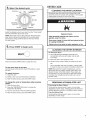
DRYER SAFETY
Your safety and the safety of others
are very important.
We have provided many important safety messages in this manua{ and on your app{iance. Always read and obey al{ safety
messages.
This is the safety alert symbol.
This symbol alerts you to potential hazards that can kill or hurt you and others.
All safety messages wil{ fo{{ow the safety alert symbol and either the word "DANGER" or "WARNING."
These words mean:
You can be killed or seriously injured if you don't immediate!Y
follow instructions.
You can be killed or seriously injured if you don't follow
instructions.
All safety messages will tel{ you what the potential hazard is, te{{ you how to reduce the chance of injury, and te{{ you what can
happen if the instructions are not foi{owed.
State of California Proposition 65 Warnings:
2
WARN{NG: This product contains one or more chemicals
known to the State of California to cause cancer.
WARNING: This product contains one or more chemicals
reproductive harm.
known to the State of California to cause birth defects or other
WARNING
- Clothes dryer
installation
- ,,ei kofFir°,,
must be performed
= install the clothes dryer according
by a qualified installer.
to the manufacturer's
instructions
and local codes.
= Do not install a clothes dryer with fle×ible plastic venting materials or fle×ible metal
(foil type) duct. if fle×ible metal duct is installed, it must be of a specific type identified
by the appliance
manufacturer
as suitable for use with clothes dryers. Fle×ible venting
materials are known to collapse, be easily crushed, and trap lint. These conditions will
obstruct clothes dryer airflow and increase the risk of fire.
= To reduce the risk of severe injury or death, follow
= Save these
instructions.
instructions.
iMPORTANT
WARNING:
all installation
SAFETY INSTRUCTIONS
To reduce the risk of fire, electric shock, or injury to persons when using the dryer, follow basic precautions,
including the following:
[]
Read all instructions
[]
Do not place items exposed to cooking oils in your dryer.
Items contaminated with cooking oils may contribute to
a chemical reaction that could cause a load to catch fire.
[]
Do not dry articles that have been previously cleaned in,
washed in, soaked in, or spotted with gasoline, dry=
cleaning solvents, or other flammable or explosive
substances as they give off vapors that could ignite or
explode.
[]
before using the dryer.
Do not allow children to play on or in the dryer. Close
supervision of children is necessary when the dryer is
used near children.
[]
Do not repair or replace any part of the dryer or attempt
any servicing unless specifically recommended in this
Use and Care Guide or in published user-repair
instructions that you understand and have the skills to
carry out.
[]
Do not use fabric softeners or products to eliminate static
unless recommended by the manufacturer of the fabric
softener or product.
[]
Do not use heat to dry articles containing foam rubber or
similarly textured rubber=like materials.
Clean lint screen before or after each load.
[]
[]
Keep area around the exhaust opening and adjacent
surrounding areas free from the accumulation of lint, dust,
and dirt.
Do not reach into the dryer if the drum is moving.
[]
[]
Do not install or store the dryer where it will be exposed
to the weather.
The interior of the dryer and exhaust vent should be
cleaned periodically by qualified service personnel.
[]
[]
Do not tamper with controls.
See "Electrical Requirements" located in the installation
instructions for grounding instructions.
[]
Before the dryer is removed from service or discarded,
remove the door to the drying compartment.
[]
SAVE THESE INSTRUCTIONS
OPERATING INSTRUCTIONS
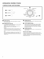
CONTROL PANEL AND FEATURES
0
timed dry minutes
sensor dry cotton/linen
stop
O_start
40
0 mtemperature
/ .............
_ J-Lnorrna[
6O
low
sensor dry synthetics
dam
0_
,---------O
power
iron
O
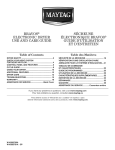
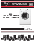
START BUTTON
Press to start a cycle. Indicator light will glow to indicate
the cycle has started.
TEMPERATURE
BUTTON
The Temperature Control button lets you choose between
a normal and low drying temperature.
0
0
NOTE: Always refer to the care label on the garment to
determine whether it can be tumble dried.
Normal
The Normal temperature setting is for sturdy fabrics, such
as cotton, linen, and denim. If the Temperature Control
button is not pressed in, the temperature setting is Normal.
Low
The Low setting is for synthetics, such as cotton/polyester
blend, rayon, acetate, washable silk, or nylon. If the
Temperature Control button is pressed in, the temperature
setting is Low.
4
0
normal
._dry
power
indicator
POWER BUTTON
Press to turn the dryer on and off. Indicator light will flash
to indicate the power is on.
CYCLE CONTROL
KNOB
Use your dryer's Cycle Control knob to select available
cycles on your dryer. Turn the knob to select a cycle for
your laundry load. Indicator light will flash to indicate a
cycle has been selected. See "Cycle Guide" for detailed
descriptions of cycles.
POWER INDICATOR
This light flashes when the power is on and glows when a
cycle is running.
END OF CYCLE
SIGNAL
The dryer sounds a signal to let you know when the cycle is
complete. The signal is not adjustable and cannot be turned off.
The signal is helpful when you are drying permanent press,
synthetics, and other items that should be removed promptly
at the end of the cycle.
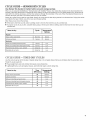
CYCLE GUIDE -- SENSOR DRY CYCLES
Use Sensor
Dry Cycles for better
fabric
care and energy
savings
When you are using the GentleBreeze
Drying System with Intellibry ® Sensor, two metal strips located on the dryer determine the
dryness of the load. When there is moisture left in the clothes, the dryer will continue to run. As clothes begin to dry, the amount of
water left in the clothes decreases, and the timer advances through the remainder of the cycle. When the selected dryness level is
reached, the dryer goes into a cool-down period of up to 15 minutes.
TM
Sensor dry cycles may be used for most loads. Sensor dry cycles give the best drying results in the shortest time. Drying time varies
according to the type of fabric, size of the load, and dryness setting.
After drying a load, check the dryness.
[] If the load is drier than you like, select a setting closer to Iron Dry the next time you dry a similar load.
[] If a load is not as dry as you like, complete drying using a Timed cycle. Select a setting closer to More Dry the next time you dry
a similar load.
!
!
Setting:
Regular
Heaw cottons
and denims
Cottons and linens
More Dry
Normal
Normal
Normal
Normal
Low
Synthetics
White and colorfast
permanent press
White and colorfast
items that require ironing
Polyester/acrylic
blends, rayon, acetate
Washable silk and nylon
Iron Dry
Low
Damp Dry
Low
Damp Dry
Low
CYCLE GUIDE -- TI ED DRY CYCLES
Use this cycle to get up to 60 minutes of heated drying time or to complete drying if items are still damp after the automatic
Timed Dry is also useful for:
[] Heavyweight items and work clothes that require a long drying time.
[] Lightweight items, such as lingerie, blouses, and knits that require a short drying time.
Items to dry:
...........
Time
(Minutes}:
Temperature
Setting:
Heavy cottons and denims
60
Normal
Cottons and linens
40
Normal
White and colorfast permanent press
40
Low
White and colorfast items that require ironing
40
Low
Polyester/acrylic blends, rayon, acetate
40
Low
Washable silk and nylon
40
Low
cycle.
USING YOUR DRYER
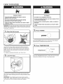
Explosion Hazard
Keep flammable materials and vapors, such as
gasoline, away from dryer.
Do not dry anything that has ever had anything
flammable on it (even after washing).
Failure to follow these instructions
explosion, or fire.
can result in death,
WARNING: To reduce the risk of fire, electric shock, or injury to
persons, read the IMPORTANT SAFETY INSTRUCTIONS before
operating this appliance.
Fire Hazard
No washer can completely
remove oil.
Do not dry anything that has ever had any type of oil on
it (including cooking oils).
Do not dry items containing foam, rubber,
this dryer.
Failure to follow these instructions
or fire.
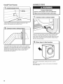
3. Press
or plastic in
can result in death
POWER
power
Press the POWER button to turn on the dryer. The indicator
light will flash to indicate that the power is on.
--_
4,
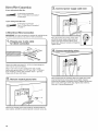
Clean the lint screen before each load. Pull the lint screen
straight up. Open lint screen. Roll lint off the screen with your
fingers. Do not rinse or wash screen to remove lint. Wet lint is
hard to remove. Close lint screen. Push the lint screen firmly
back into place.
For additional cleaning information, see "Dryer Care."
2.
Load the dryer
Open the door by pulling on the handle. Place laundry in the
dryer. Add a static reducing sheet to wet load, if desired. Close
the door.
iMPORTANT: Do not tightly pack the dryer. Items need to
tumble freely. Tightly packing the load can lead to poor drying
performance and may increase wrinkling and tangling.
6
Press TEMPERATURE
J-L normal
temperature
tow
Press the TEMPERATURE button to select the recommended
temperature
setting for the type of load being dried.
5. Select the desired
DRYER CARE
cycle
timed dry minutes
sensor dry cotton/linen
stop
40
more dry
block CLEANING
the air flow for proper
operation.
This includes
THE dryer
DRYER
LOCATION
l clearing
eep dryer
area
clear andin free
items
that would
piles
of laundry
front from
of the
dryer.
,normal
60
dry
dam
amp
iron dr
normal
dry
Select the desired cycle for your load. See the "Cycle Guide"
for more information about each cycle.
Explosion Hazard
NOTE: Most loads may be dried using the Normal dryness
level, which is shown in bold letters on the control panel.
Normal is the energy preferred dryness level and will use
the least energy.
Keep flammable materials and vapors, such as
gasoline, away from dryer.
Place dryer at least 18 inches (460 ram) above the floor
for a garage installation.
Failure to do so can result in death, explosion,
6.
Press START to begin
or fire.
cycle
CLEANING
THE DRYER INTERIOR
To clean dryer drum
1. Use a mild hand dish detergent mixed at a low
concentration with very warm water, and rub with
a soft cloth.
2. Rinse well with a wet sponge or towel.
3. Tumble a load of clean clothes or towels to dry drum
OR
Press and hold the START button to begin the cycle.
Use a microfiber cloth and hot water in a spray bottle
to clean the drum and a second microfiber towel to dry.
To stop your dryer at any time:
Turn the Cycle Control knob to the STOP position or open
the door.
NOTE: Garments that contain unstable dyes, such as
denim blue jeans or brightly colored cotton items, may
discolor the rear of the dryer interior. These stains are
not harmful to your dryer and will not stain future loads
of clothes. Dry unstable dye items inside out to avoid
transfer of dye.
To restart the dryer:
1, Close the door.
2. Select a new cycle and temperature
(if desired).
3. After the beep sounds, press the START button.
r
To change the cycle or temperature
START:
1. Open the dryer door.
after
pressing
2. Press the TEMPERATURE button to change the
temperature (if desired).
3. Turn the cycle knob to the new desired position.
4. After the beep sounds, press the START button.
REMOVING
ACCUMULATED
LINT
From Inside the Dryer Cabinet
Lint should be removed every 2 years, or more often,
depending on dryer usage. Cleaning should be done by a
qualified appliance servicer or ventilation system cleaner.
From the Exhaust Vent
Lint should be removed every 2 years, or more often,
depending on dryer usage.
1
CLEANING
THE LiNT SCREEN
Every load cleaning
The lint screen is located in the door opening of the dryer.
The control panel has an indicator light to remind you to
clean the lint screen before each load. A screen blocked
by lint can increase drying time.
To clean:
1. Pull the lint screen straight up. Open lint screen. Roll lint
off the screen with your fingers. Do not rinse or wash
screen to remove lint. Wet lint is hard to remove.
fVACATION,
STORAGE,
AND MOVING
CARE
Install and store your dryer where it will not freeze. Because
some water may stay in the hoses, freezing can damage
your dryer. If storing or moving your dryer during freezing
weather, winterize it.
Non=Use
or Storage
Care
Operate your dryer only when you are at home. If you will
be on vacation or not using your dryer for an extended
period of time, you should:
1. Unplug dryer or disconnect
power.
2. Clean lint screen. See "Cleaning the Lint Screen."
Moving
Care
For power supply cord-connected dryers:
1. Unplug the power supply cord.
2. Make sure leveling legs are secure in dryer base.
3. Use masking tape to secure dryer door.
2. Close lint screen. Push the lint screen firmly back into
place.
iMPORTANT:
[]
Do not run the dryer with the lint screen loose,
damaged, blocked, or missing. Doing so can cause
overheating and damage to both the dryer and fabrics.
[]
If lint falls off the screen into the dryer during removal,
check the exhaust hood and remove the lint. See
"Venting Requirements."
As needed cleaning
Laundry detergent and fabric softener residue can build
up on the lint screen. This buildup can cause longer drying
times for your clothes, or cause the dryer to stop before
your load is completely dry. The screen is probably clogged
if lint falls off while the screen is in the dryer.
Clean the lint screen with a nylon brush every 6 months,
or more frequently, if it becomes clogged due to a residue
buildup.
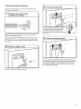
To wash:
1. Roll lint off the screen with your fingers.
2. Wet both sides of lint screen with hot water.
3. Wet a nylon brush with
hot water and liquid detergent.
Scrub lint screen with the brush
to remove residue buildup.
4. Rinse screen with hot water.
5. Thoroughly dry lint screen with a clean towel.
Reinstall screen in dryer.
8
Electrical
Shock Hazard
Disconnect power before servicing.
Replace all parts and panels before operating.
Failure to do so can result in death or electrical shock.
For direct=wired
dryers:
1. Disconnect
power.
2. Disconnect
wiring.
3. Make sure leveling legs are secure in dryer base.
4. Use tape to secure dryer door.
Reinstalling
the Dryer
Follow the "Installation Instructions" to locate, level, and
connect the dryer.
INSTALLATION INSTRUCTIONS
INSTALLATION REQUIREMENTS
TOOLS
AND
PARTS
Parts needed:
Gather the required tools and parts before starting installation.
Tools needed:
(Not supplied with dryer)
Vent clamps
Vent elbows and ductwork
Additional parts may be required, depending on your
installation. Check local codes. Check existing electrical
supply and venting. Read "Electrical Requirements" and
"Venting Requirements" before purchasing parts.
Flat-blade screwdriver
Wood block
if using a power supply cord:
Use a UL listed power supply cord kit marked for use with
clothes dryers. The kit should contain:
[] A UL listed 30-amp power supply cord, rated 120/240 volt
minimum. The cord should be type SRD or SRDT and be
at least 4 ft. (1.22 m) long. The wires that connect to
the dryer must end in ring terminals or spade terminals
with upturned ends.
[] A UL listed strain relief.
Parts supplied:
Wire stripper (direct wire
installations)
Tin snips (new vent
installations)
1/4" (7 mm) nut driver
(recommended)
Adjustable wrench that
opens to 1" (25 mm) or
hex-head socket wrench
Parts package is located in dryer drum. Check that all parts
are included.
NOTE: Do not use leveling legs supplied if installing with
a pedestal or a stack kit.
Coupling
Options:
(Not supplied with dryer)
Pedestal
Level
Caulking gun and
compound (for installing
new exhaust vent)
You may order a pedestal
separately for this dryer. This
pedestal will add about 12"
(305 mm) to the height of your unit
for a total height of approximately
45" (1.14 m).
To order, call the dealer from
whom you purchased your dryer
or refer to the "Assistance or
Service" section of this manual.
Ask for Model Number LAB0050PQ.
Stack kit
Are you planning to stack your washer and dryer? Your dryer is
shipped with Stack Kit W10178021, which fits Maytag washer
models starting with MHWC.
If you have any other washer model, call the dealer from whom
you purchased your dryer or refer to the "Assistance or Service"
section of this manual.
Torx ° T20 screwdriver
® TORX is a registered trademark
of Saturn Fasteners, Inc.
LOCATION REQUIREMENTS
Check code requirements. Some codes limit, or do not permit,
installing dryer in garages, closets, mobile homes, or sleeping
quarters. Contact your local building inspector.
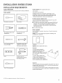
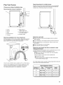
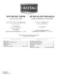
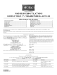
DRYER DIMENSIONS
Front view:
233/8"
(594
mra)--IIP-
331/4"
(845 ram)
Explosion Hazard
Keep flammable materials and vapors, such as
gasoline, away from dryer.
Place dryer at least 18 inches (460 ram) above the floor
for a garage installation.
I'
Failure to do so can result in death, explosion, or fire.
You will need:
Side view:
[] A location allowing for proper exhaust installation.
See "Venting Requirements."
[] A separate 30 amp circuit.
39"
(991
__ram)
[] If using power supply cord, a grounded electrical outlet
located within 2 ft. (610 mm) of either side of dryer.
See "Electrical Requirements."
23114" __
(603 ram)
[] Floor must support dryer weight of 115 Ibs. (52 kg).
Also consider weight of companion appliance.
[] Level floor with maximum slope of 1" (25 mm) under entire
dryer. If slope is greater than 1" (25 mm), install Extended
Dryer Feet Kit, Part Number 279810. If not level, clothes
may not tumble properly and automatic sensor cycles may
not operate correctly.
[] For garage installation, place dryer at least 18" (460 mm)
above floor. If using a pedestal, you will need 18" (460 mm)
to bottom of dryer.
[] The dryer must not be installed or stored in an area where
it will be exposed to water and/or weather.
iMPORTANT: Do not operate, install, or store dryer where
it will be exposed to water, weather, or at temperatures below
45 ° F (7° C). Lower temperatures may cause dryer not to
shut off at end of sensor cycles, resulting in longer drying times.
Back view:
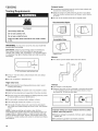
installation Clearances
For each arrangement, consider allowing more space for ease
of installation and servicing, spacing for companion appliances,
and clearances for walls, doors, and floor moldings. Space
must be large enough to allow door to fully open. Add spacing
on all sides of dryer to reduce noise transfer. If a closet door
or Iouvered door is installed, top and bottom air openings
in door are required.
NOTE: Most installations
require a minimum of
5" (127 mm) clearance
behind dryer for exhaust
vent with elbow. See
"Venting Requirements."
31/4"
(83 ram)
___
Check code requirements. Some codes limit, or do not permit,
installation of the dryer in garages, closets, mobile homes, or
sleeping quarters. Contact your local building inspector.
113/4"
(299 mm)
10
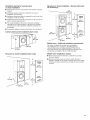
Installation spacing for recessed
or closet installation
area
[] All dimensions
allowed.
and minimum spacing
show recommended
Recessed or closet installation = Stacked with stack
kit {Accessory):
12 mn
(305 ram)
[] Additional spacing should be considered for ease of
installation and servicing.
,= ....
[] Additional clearances might be required for wall, door, floor
moldings, and dryer venting.
[] Additional spacing should be considered on all sides of the
dryer to reduce noise transfer.
[] For closet installation with a door, minimum ventilation
openings in the top and bottom of the door are required.
Louvered doors with equivalent ventilation openings are
acceptable.
[] Companion
48 in.2
(310 cm2}
v
6
(1670 ram}
appliance spacing should also be considered.
24 in. 2
Custom undercounter
installation (dryer only):
_
5,/." ,,, : El!i!i
3"
(155 cm 2}
(76 ram}
"1"
125mm}
1_ j
(25 ram}
Mobile
home
= Additional
installation
requirements:
This dryer is suitable for mobile home installations.
The installation must conform to the Manufactured
Home Construction and Safety Standard, Title 24 CFR,
Part 3280 (formerly the Federal Standard for Mobile home
construction and Safety, Title 24, HUD Part 280).
)
Recessed or closet installation {dryer only):
Mobile home installations
require:
[] Metal exhaust system hardware, available for purchase
from your dealer.
[] Special provisions must be made in mobile homes to
introduce outside air into dryer. Openings (such as a nearby
window) should be at least twice as large as dryer exhaust
opening.
(76 mm}
1 ml
1"
(25 ram}
(25 ram}
11
ELECTRICAL REQUIREMENTS
if your outlet looks like this:
it is your responsibility:
[] To contact a qualified electrical installer.
[]
To be sure that the electrical connection is adequate and in
conformance with the National Electrical Code, ANSI/NFPA
70 - latest edition and all local codes and ordinances.
The National Electrical Code requires a 4-wire power supply
connection for homes built after 1996, dryer circuits involved
in remodeling after 1996, and all mobile home installations.
[]
[]
[]
A copy of the above code standards can be obtained from:
National Fire Protection Association, One Batterymarch
Park, Quincy, MA 02269.
To supply the required 3 or 4 wire, single phase, 120/240
volt, 60 Hz, AC only electrical supply (or 3 or 4 wire, 120/208
volt electrical supply, if specified on the serial/rating plate)
on a separate 30-amp circuit, fused on both sides of the
line. Connect to an individual branch circuit. Do not have
a fuse in the neutral or grounding circuit.
Do not use an extension cord.
If codes permit and a separate ground wire is used, it is
recommended that a qualified electrician determine that
the ground path is adequate.
Electrical
Connection
To properly install your dryer, you must determine the type
of electrical connection you will be using and follow the
instructions in "Electric installation."
[] This dryer is manufactured ready to install with a 3-wire
electrical supply connection. The neutral ground conductor
is permanently connected to the neutral conductor (white
wire) within the dryer. If the dryer is installed with a 4-wire
electrical supply connection, see "4-Wire Direct Wire
Connection."
[] A 4-wire power supply connection must be used when the
appliance is installed in a location where grounding through
the neutral conductor is prohibited. Grounding through the
neutral is prohibited for (1) new branch-circuit installations
after 1996, (2) mobile homes, (3) recreational vehicles, and
(4) areas where local codes prohibit grounding through the
neutral conductors.
if using a power supply cord:
Use a UL listed power supply cord kit marked for use with
clothes dryers. The kit should contain:
[] A UL listed 30-amp power supply cord, rated 120/240 volt
minimum. The cord should be type SRD or SRDT and be
at least 4 ft. (1.22 m) long. The wires that connect to
the dryer must end in ring terminals or spade terminals
with upturned ends.
[] A UL listed strain relief.
4-wire receptacle
(14-30R)
Then choose a 4-wire power supply cord with
ring or spade terminals and UL listed strain
relief. The 4-wire power supply cord, at least
4 ft. (1.22 m) long, must have four 10-gauge
copper wires and match a 4-wire receptacle of
NEMA Type 14-30R. The ground wire (ground
conductor) may be either green or bare. The
neutral conductor must be identified by a
white cover.
if your outlet looks like this:
3-wire
receptacle
Then choose a 3-wire power supply cord with
ring or spade terminals and UL listed strain
relief. The 3-wire power supply cord, at least
4 ft. (1.22 m) long, must have three 10-gauge
copper wires and match a 3-wire receptacle of
NEMA Type 10-30R.
(10-30R)
If connecting
by direct wire:
Power supply cable must match power supply (4-wire or 3-wire)
and be:
[] Flexible armored cable or nonmetallic sheathed copper
cable (with ground wire), covered with flexible metallic
conduit. All current-carrying wires must be insulated.
[] 10-gauge solid copper wire (do not use aluminum) at least
5 ft. (1.52 m) long.
GROUNDING
[] For a grounded, cord-connected dryer:
This dryer must be grounded. In the event of malfunction or
breakdown, grounding will reduce the risk of electric shock
by providing a path of least resistance for electric current.
This dryer uses a cord having an equipment-grounding
conductor and a grounding plug. The plug must be plugged
into an appropriate outlet that is properly installed and
grounded in accordance with all local codes and ordinances.
[] For a permanently connected dryer:
This dryer must be connected to a grounded metal,
permanent wiring system, or an equipment-grounding
conductor must be run with the circuit conductors and
connected to the equipment-grounding
terminal or lead on
the dryer.
WARNING"
Improper connection of the equipmentgrounding conductor can result in a risk of electric shock.
Check with a qualified electrician or service representative
or personnel if you are in doubt as to whether the dryer is
properly grounded. Do not modify the plug on the power
supply cord: if it will not fit the outlet, have a proper outlet
installed by a qualified electrician.
SAVE THESE
12
INSTRUCTIONS
INSTRUCTIONS
ELECTRIC INSTALLATION
For power
supply
cord
For direct wire installations:
installations:
Fire Hazard
Fire Hazard
Use a new UL listed 30 amp power supply cord.
Use 10 gauge copper wire.
Use a UL listed strain relief.
Use a UL listed strain relief.
Disconnect power before making electrical connections.
Disconnect power before making electrical connections.
Connect neutral wire (white or center wire) to center
terminal (silver).
Connect neutral wire (white or center wire) to center
terminal (silver).
Ground wire (green or bare wire) must be connected to
green ground connector.
Ground wire (green or bare wire) must be connected to
green ground connector.
Connect remaining 2 supply wires to remaining
2 terminals (gold).
Connect remaining 2 supply wires to remaining
2 terminals (gold).
Securely tighten all electrical connections.
Securely tighten all electrical connections.
Failure to do so can result in death, fire, or
electrical shock.
Failure to do so can result in death, fire, or
electrical shock.
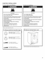
Before you start: disconnect
power.
1, Choose electrical
connection
type
Power supply cord 4-wire receptacle
(NEMA Type 14-30R).
Go to "Power Supply Cord Connection."
Power supply cord 3-wire receptacle
(NEMA Type 10-30R).
Go to "Power Supply Cord Connection."
4-wire
direct connection:
Go
to "Direct
Wire Connection."
Remove hold-down
screw and terminal block cover.
3-wire
direct connection:
Go to "Direct
Wire Connection."
13
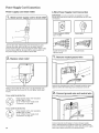
Power Supply Cord Connection
Power supply cord strain relief:
g-Wire
Power Supply Cord Connection
IMPORTANT: A 4-wire connection is required for mobile
homes and where local codes do not permit the use of 3-wire
connections.
Unscrew the strain relief (A) from the terminal block cover.
Unscrew the strain relief nut (B) from the strain relief (A).
Put the power supply cord (C) through the strain relief nut (B),
then the strain relief (A). Be sure that the wire insulation on
the power supply cord is inside the strain relief.
4-wire receptacle (NEMA
type 14-30R)
4-prong plug
Spade terminals with
upturned ends
Ring terminals
i,
2,
Replace
strain
Remove
neutral ground
wire
relief
A
B
Replace strain relief (B) (with power cord [D] inserted) back
into the terminal block cover (A). Do not tighten strain relief
nut (C).
Remove the neutral ground wire (F) located inside the dryer
cabinet, behind the external ground conductor screw (A).
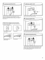
2,
Connect
ground
wire and neutral
wire
If your outlet looks like this:
Power supply cord 4-wire receptacle
(NEMA Type 14-30R):
Go to "4-Wire Power Supply Cord
Connection" on this page.
If your outlet looks like this:
(_)
14
(NEMA Type 10-30R):
Go to "3-Wire Power Supply Cord
Power supply oncord
3-wire
Connection"
page
15. receptacle
Connect ground wire (E) (green or bare) of power supply
cord to external ground conductor screw (A). Tighten screw.
Connect neutral wire (D) (white or center wire) of power supply
cord under center screw (B) of the terminal block.
3. connect
remaining
i.
wires
Remove
center
screw
[j
,,,,
0
y/'
S-/
Connect the other wires to outer terminal block screws.
Tighten screws. Replace the terminal block cover on the back
of the dryer. Tighten strain relief nut. Now, go to "Venting
Requirements."
Remove center terminal block screw (B).
3=Wire Power Supply Cord Connection
Use where local codes permit connecting
conductor to neutral wire.
cabinet-ground
3-wire receptacle (NEMA
type 10-30R)
3-prong plug
Spade terminals with
upturned ends
Ring terminals
Connect neutral wire (white or center) (D) of power supply cord
under center terminal block screw (B). Tighten screw.
Connect remaining wires under outer terminal block screws.
Tighten screws. Finally, reinsert tab of terminal block cover
into slot of dryer rear panel. Tighten strain relief nut. Now,
go to "Venting Requirements."
15
Direct Wire Connection
if your wiring looks like this:
4-wire direct connection:
Go to "4-Wire Direct Connection"
on this page.
if your wiring looks like this:
3-wire direct connection:
Go to "3-Wire Direct Connection"
on page 17.
4-Wire
Direct Wire Connection
iMPORTANT: A 4-wire connection is required for mobile homes
and where local codes do not permit 3-wire connections.
"_,
Prepare your 4-wire cable
for direct connection
Direct wire cable must have 5 ft. (1.52 m) of extra length so
dryer may be moved if needed.
Strip 5" (127 mm) of outer covering from end of cable,
leaving bare ground wire at 5" (127 mm). Cut 11/2" (38 mm)
from remaining 3 wires. Strip insulation back 1" (25 mm).
Shape ends of wires into hooks.
Place hooked ends of remaining direct wire cable wires under
outer terminal block screws (hooks facing right). Squeeze
hooked ends together and tighten screws. Replace the terminal
block cover on the back of the dryer. Tighten strain relief nut.
Now, go to "Venting Requirements."
Remove the neutral ground wire (white) (F) located inside the
dryer cabinet, behind the external ground conductor screw (A).
16
f
3=Wire Direct Wire Connection
Use where local codes permit connecting
conductor to neutral wire.
cabinet-ground
3,
Connect
neutral wire
f
"1, Prepare
for direct
your 3-wire
cable
connection
Place hooked end of neutral wire (white
or center) (D) of direct wire cable under
center terminal block screw (B), hook
facing right. Squeeze hooked end together.
Tighten screw.
Direct wire cable must have 5 ft. (1.52 m) of extra length so
dryer may be moved if needed.
Strip 31/2'' (89 mm) of outer covering from end of cable. Strip
insulation back 1" (25 mm). If using 3-wire cable with ground
wire, cut bare wire even with outer covering. Shape wire ends
into hooks.
2,
Remove
r4,
Connect
remaining
wires
center screw
Place hooked ends of remaining direct wire cable wires under
outer terminal block screws (hooks facing right). Squeeze hooked
ends together and tighten screws. Replace the terminal block
cover on the back of the dryer. Tighten strain relief nut. Now,
go to" Venting Requirements."
i
i
Remove
center
terminal
block
screw
(B).
17
Exhausthoods:
VENTING
[] An exhaust hood should cap the vent to keep rodents and
insects from entering the home.
Venting Requirements
[] Must be at least 12" (305 mm) from ground or any object
that may obstruct exhaust (such as flowers, rocks, bushes,
or snow).
[] Do not use an exhaust hood with a magnetic latch.
Recommended
Styles:
Fire Hazard
Use a heavy metal vent.
Do not use a plastic vent.
Do not use a metal foi( vent.
Louvered Hood
Failure to follow these instructions can result in death
or fire.
Acceptable
Box Hood
Style:
WARNING:
To reduce the risk of fire, this dryer MUST BE
EXHAUSTED OUTDOORS.
IMPORTANT: Observe all governing codes and ordinances.
Dryer exhaust must not be connected into any gas vent,
chimney, wall, ceiling, attic, crawlspace, or a concealed space
of a building. Only rigid or flexible metal vent shall be used for
exhausting.
Angled Hood
Elbows:
[] 45 ° elbows provide better airflow than 90 ° elbows.
(
0'
Be
(102 ram)
t
4" (102 ram) heavy metal exhaust vent
[] Only a 4" (102 mm) heavy metal exhaust vent and clamps
may be used.
[] Do not use plastic or metal foil vent.
Rigid
metal
vent:
[] Recommended for best drying performance
crushing and kinking.
Flexible
metal
and to avoid
vent: (Acceptable only if accessible to clean)
[] Must be fully extended and supported
in final dryer location.
Clamps:
[] Use clamps to seal all joints.
[] Exhaust vent must not be connected or secured with screws
or other fastening devices that extend into interior of duct
and catch lint. Do not use duct tape.
[] Remove excess to avoid sagging and kinking that may result
in reduced airflow and poor performance.
[] Do not install in enclosed walls, ceilings, or floors.
[] The total length should not exceed 73/4ft. (2.4 m).
[] The length of flexible metal vent used must be included in
the overall vent system design as shown in the "Vent System
Chart."
NOTE: If using an existing vent system, clean lint from
entire length of the system and make sure exhaust hood is not
plugged with lint. Replace plastic or metal foil vents with rigid
metal or flexible metal vents. Review "Vent System Chart" and,
if necessary, modify existing vent system to achieve best drying
performance.
18
improper venting can cause moisture
indoors, which may result in:
[] Moisture damage to woodwork,
carpets, etc.
[] Housecleaning
and lint to collect
furniture, paint, wallpaper,
problems and health problems.
Special
Plan Vent System
Choose
your exhaust
Recommended
installation
provisions
for mobile
homes:
Exhaust vent must be securely fastened to a noncombustible
portion of mobile home and must not terminate beneath the
mobile home. Terminate exhaust vent outside.
type
exhaust installation:
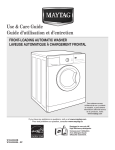
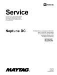
B,
---------C
(
A. Dryer
B. Elbow
F. Rigid metal or
flexible metal vent
C. Wall
D. Exhaust hood
G. Vent length necessary
to connect elbows
E. Clamps
H. Exhaust out_t
Alternate installations for close clearances:
Venting systems come in many varieties. Select the type best
for your installation. A close-clearance installation is shown
below. Refer to the manufacturer's instructions.
Determine
vent path:
[] Select route that will provide straightest and most direct
path outdoors.
[] Plan installation to use fewest number of elbows and turns.
[] When using elbows or making turns, allow as much room
as possible.
[] Bend vent gradually to avoid kinking.
[] Use as few 90 ° turns as possible.
Determine
vent length and elbows
needed for best
drying performance:
Use the following "Vent System Chart" to determine type of vent
material and hood combinations acceptable to use.
NOTE: Do not use vent runs longer than those specified
in "Vent System Chart."
Exhaust systems longer than those specified will:
[] Shorten life of dryer.
[] Reduce performance, resulting in longer drying times
and increased energy usage.
Over-the-top
installation (also available with one offset elbow)
Over-the-Top Installation Kit Part Number 4396028 for close
clearance alternate installation is available for purchase.
For ordering information, see "Assistance or Service."
The "Vent System Chart" provides venting requirements that will
help achieve best drying performance.
Vent System
Chart
Number of
90 ° elbows
Type
of vent
Box/Iouvered
hoods
Angled
hoods
0
Rigid metal
90 ft. (27.4 m)
80 ft. (24.4 m)
1
Rigid metal
80 ft. (24.4 m)
70 ft. (21.3 m)
2
Rigid metal
70 ft. (21.3 m)
60 ft. (18.3 m)
19
CONNECT VENT
Install Vent System
i
. install exhaust
"
hood
Excessive Weight Hazard
Use two or more people to move and install dryer.
Failure to do so can result in back or other injury.
install exhaust hood and use caulking compound
exterior wall opening around exhaust hood.
_.
Connect
vent to exhaust
to seal
hood
Using a 4" (102 mm) clamp, connect vent to
in dryer. If connecting to existing vent, make
clean. Dryer vent must fit over dryer exhaust
exhaust hood. Check that vent is secured to
with a 4" (102 mm) clamp.
. Move dryer
to final
exhaust outlet
sure vent is
outlet and inside
exhaust hood
location
Vent must fit over the exhaust hood. Secure vent to exhaust
hood with 4" (102 mm) clamp. Run vent to dryer location using
straightest path possible. Avoid 90 ° turns. Use clamps to seal
all joints. Do not use duct tape, screws, or other fastening
devices that extend into interior of vent to secure vent,
because they can catch lint.
Move dryer to final location, taking care not to crush or
kink vent.
After dryer is in place, remove corner posts and cardboard
from under dryer.
2O
LEVEL DRYER
1.
COMPLETE INSTALLATION
CHECKLIST
Level dryer
Place
level here
[_
Check that all parts are now installed. If there is an extra
part, go back through steps to see what was skipped.
[_
Check that you have all of your tools.
[_
Dispose of/recycle all packaging materials.
[_
Check dryer's final location. Be sure vent is not crushed
or kinked.
C3Check that dryer is level. See "Level Dryer".
C3 Remove film on console and any tape remaining
C3Wipe dryer drum interior thoroughly with a damp
on dryer.
cloth to
remove any dust.
Check levelness of dryer from
side to side. Repeat from front to back.
NOTE: The dryer must be level for the moisture sensing system
to operate correctly.
[_
Read "Using Your Dryer."
[_
For power supply cord installation, plug into a grounded
outlet. For direct wire installation, turn on power.
[_
Set the dryer on a full heat cycle (not an air cycle) for
20 minutes and start the dryer.
If dryer will not start, check the following:
* Controls are set in a running or "On" position.
. Start button has been pushed firmly.
Not Level
2,
Adjust leveling
LEVEL
Not Level
legs
.
Dryer is plugged into an outlet and/or electrical
supply.
.
Household fuse is intact and tight, or circuit breaker
has not tripped.
. Dryer door is closed.
NOTE: You may notice an odor when dryer is first heated.
This odor is common when heating element is first used.
The odor will go away.
If dryer is not level, prop up using a wood block, use wrench
to adjust legs up or down, and check again for levelness.
Once dryer is level, make sure all four legs are snug against
the floor and dryer does not rock.
21
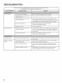
TROUBLESHOOTING
f
First try the solutions suggested here or visit our website at www.maytag.com/help
for assistance and to possibly avoid a service call.
mfyou experience
Dryer will not run
Possibme Causes
Somution
Door not closed completely.
Make sure the dryer door is closed completely.
START button not pressed firmly or
held long enough.
Press and hold the START button 2-5 seconds.
Household fuse is blown or circuit
breaker has tripped.
There
dryer.
circuit
circuit
incorrect power supply.
Electric dryers require 240-volt power supply.
Check with a qualified electrician.
Wrong type of fuse.
Use a time-delay
Household fuse is blown or circuit
breaker has tripped.
The drum may be turning, but you may not have heat. Electric
dryers use 2 household fuses or circuit breakers. Replace the
fuses or reset the circuit breaker. If the problem continues, call
an electrician.
incorrect power supply.
Electric dryers require 240-volt power supply.
Check with a qualified electrician.
Thumping noise
Dryer hasn't been used in a while.
This is normal. The thumping
minutes of use.
Rattling or vibrating
noise
A small object caught between the
edges of dryer drum.
Check the front and rear edges of the drum for small objects.
Clean out pockets before laundering.
Dryer isn't properly leveled.
The dryer may vibrate if not properly installed. See "Level
Dryer." All four dryer feet should be in firm contact with the
floor.
Clothing is bailed up in dryer.
When balled up, the load will bounce, causing the dryer to
vibrate. Separate the load items and restart the dryer.
Dryer will not heat
-_
may be 2 household fuses or circuit breakers for the
Check that both fuses are intact and tight, or that both
breakers have not tripped. Replace the fuses or reset the
breaker. If the problem continues, call an electrician.
fuse.
sound should diminish after a few
J
22
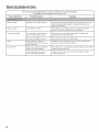
TROUBLESHOOTING
Fire Hazard
Explosion Hazard
Use a heavy metal vent.
Keep flammable materials and vapors, such as
gasoline, away from dryer.
Do not use a plastic vent.
Do not use a metal foil vent.
Failure to follow these instructions
or fire.
f
can result in death
Place dryer at least 18 inches (460 ram) above the floor
for a garage installation.
Failure to do so can result in death, explosion, or fire.
First try the solutions suggested here or visit our website at www.maytag.com/help
for assistance and to possibly avoid a service call.
Clothes are not drying
satisfactorily or drying
times are too long
Cycle time is too short
Lint on load
Lint screen is clogged with lint.
Clean lint screen before each load.
The exhaust vent or outside
exhaust hood is clogged with lint,
restricting air movement.
Run the dryer for 5=10 minutes. Hold your hand under
the outside exhaust hood to check air movement. Hfyou
do not feel air movement, clean exhaust system of lint
or replace exhaust vent with heavy metal or flexible metal vent.
See "Venting."
The exhaust vent is not the correct
length,
Check that the exhaust vent is not too long or has
too many turns. Long venting will increase drying times.
See "Venting."
The exhaust vent diameter is not
the correct size.
Use 4" (102 mm) diameter vent material.
The load is too large and heavy
to dry quickly.
Separate the load to tumble freely.
Fabric softener sheets are blocking
the grille.
The air outlet grille is just inside the door, behind the lint screen.
Check that it is not blocked by a fabric softener sheet.
Use only one fabric softener sheet, and use it only once.
The dryer is located in a room with
temperature below 45°F (7°C).
Proper operation of dryer cycles requires temperatures
45°F (7°C).
The dryer is located in a closet.
Closet doors must have ventilation openings at the top
and bottom of the door. The front of the dryer requires
a minimum of 1" (25 mm) of airspace, and, for most
installations, the rear of the dryer requires 5" (127 mm).
See "Location Requirements."
The load may not be contacting the
sensor strips on Sensor Cycles.
Level the dryer. See "Level Dryer." All four dryer
feet should be in firm contact with the floor.
The sensor cycle is ending early.
Change the dryness level setting on Sensor Cycles. Increasing
or decreasing the dryness level will change the amount of
drying time in a cycle. If loads are consistently ending too early,
see also "Cycle Guide = Sensor Dry Cycles."
Lint screen is clogged with lint.
Clean lint screen before each load.
above
23
TROUBLESHOOTING
f
First try the solutions suggested here or visit our website at www.maytag.com/help
for assistance and to possibly avoid a service call.
mfyou experience
Stains on load
Hmproper use of fabric softener.
Add dryer fabric softener sheets at the beginning of the cycle.
Fabric softener sheets added to a partially dried load can
stain your garments.
Loose dyes in clothes.
Drum stains are caused by dyes in clothing (usually blue
jeans). These will not transfer to other clothing.
The load was not removed from
dryer at the end of the cycle,
Refer to garment care label instructions.
garments are not recommended.
The dryer was tightly packed.
Dry smaller loads that can tumble freely.
Odors
Recent painting, staining, or
varnishing in the area where your
dryer is located.
Ventilate the area. When the odors or fumes are gone from
the area, rewash and dry the clothing.
Load too hot
Load removed before cooldown
portion of cycle complete,
Allow the dryer to complete the cooldown
before removing the load.
Using Timed Dry cycle with a
normal temperature setting,
Select a Sensor cycle with a lower heat setting to avoid
overdrying the load.
......
Stains on drum
Loads are wrinkled
_.
24
Dry clean only
portion of the cycle
J
NOTES
25
NOTES
26
MAYTAG ® LAUNDRY WARRANTY
LIMITED
WARRANTY
For one year frorn the date of purchase, when this rna'orj appliance
is operated and rnaintained according
to instructions
attached to or
furnished with the product, Maytag brand of Whirlpool
Corporation
or Whirlpool
Canada I_P (hereafter "Maytag") will pay for factory
specified parts and repair labor to correct defects in materials or workmanship
that existed when this major appliance was purchased.
Service must be provided by a Maytag designated service company. YOUR SOLE AND EXCI_USIVE REMEDY UNDER THIS IJMITED
WARRANTY
SHAI.L BE PRODUCT REPAIR AS PROVIDED HEREIN. This limited warranty is valid only in the United States or Canada and
applies on[}/when
the major appliance is used in the country in which it was purchased. Proof of original purchase date is required to obtain
service under this limited warranty.
ITEMS EXCLUDED
This limited
warranty
FROM
WARRANTY
does not cover:
1.
Rep[acernent parts or repair
a manner that is inconsistent
2.
Service calls to correct the installation
of your major
house fuses, or to correct house wMng or plumbing.
3.
Service
4.
Damage resulting from accident,
alteration, misuse, abuse, fire, flood, acts of God, improper
with electrical or plumbing
codes, or use of products not approved by Maytag.
5.
Cosmetic damage, including scratches, dents, chips or other damage to the finish of your ma'orj appliance,
unless such damage
from defects in materials or workmanship
and is reported to Maytag within 30 days from the date of purchase.
6.
Pick up and delivery.
7.
Repairs to parts or systems resulting
8.
Expenses for travel and transportation
for product
authorized
Maytag servicer is not available.
9.
The removal and reinstallation
Maytag published
installation
calls to repair
labor if this rnajor appliance is used for other than norrna[, sing[e-farni[y
household
to published User or operator instructions
and/or installation
instructions.
or replace
appliance
This major
10. Replacement
parts or repair
easily determined.
appliance
from
appliance,
light bulbs,
is intended
unauthorized
of your major
instructions.
labor on major
appliances
to be repaired
LIMITATION
YOUR
SOI_E AND
in your
modifications
Consumable
parts are excluded
installation,
to replace
from warranty
installation
or repair
coverage.
not in accordance
results
home.
major appliance
with original
major appliance,
it is used in
made to the appliance.
if it is installed
DISCLAIMER
IMPI.IED WARRANTIES,
INCI_UDING
ANY
PARTICUI_AR PURPOSE, ARE IJMITED TO
allow limitations
on the duration of implied
gives you specific legal rights, and you also
you on how to use your
air filters or water filters.
service if your
appliance
to instruct
use or when
is located
in an inaccessible
model/serial
OF IMPLIED
numbers
in a remote
location
area where
or is not installed
that have been removed,
service
by an
in accordance
altered,
or cannot
OF REMEDIES;
EXCI_USIVE REMEDY UNDER
the 50 United
States and Canada,
be
WARRANTIES
IMPIJEI) WARRANTY
OF MERCHANTABIHTY
OR IMPHEI) WARRANTY
OF FITNESS FOR A
ONE YEAR OR THE SHORTEST PERIOD AH_OWED BY I.AW. Some states and provinces do not
warranties of merchantability
or fitness, so this limitation
may not apply to you. This warranty
may have other rights that vary from state to state or province to province.
EXCLUSION
THIS I.IMITEI)
OF INCIDENTAL
WARRANTY
AND CONSEQUENTIAL
SHAM_ BE PRODUCT
DAMAGES
REPAIR AS PROVIDED
HEREIN.
MAYTAG SHAI.I_ NOT BE I.IABI_E FOR INCIDENTAl_ OR CONSEQUENTIAl_
DAMAGES. Some states and provinces do not allow the
exclusion or limitation
of incidental or consequential
damages, so these limitations
and exclusions may not apply to you. This warranty
you specific legal rights, and you also may have other rights that vary from state to state or province to province.
If outside
with
contact
your authorized
Maytag
dealer to determine
if another
warranty
gives
applies.
If you think you need repair service, first see the "Troubleshooting"
section of the Use & Care Guide. If you are unable to resolve the problem
after checking "Troubleshooting,"
additional
help can be found by checking the "Assistance or Service" section or by calling Maytag. In the
U.S.A., call 1-800-688-9900.
In Canada, call 1-800-807-6777.
6/08
Keep this book and your sales slip together for future reference.
You must provide proof of purchase or installation date for inwarranty servmce.
Write down the following
inforrnation
to better help you obtain assistance or
You will need to know your complete
number. You can find this information
number
label
located
on the product.
about your rnajor appliance
service if you ever need it.
model number and serial
on the model and serial
Dealer
name
Address
Phone number
Model
number
Serial number
Purchase date
27
ASSISTANCE
OR SERVICE
Before callin
for assistance or service,
lease check "Troubleshootin
" or visit www ma ta com/helg
It may save
g
you the cost of a serviceP ca[[. If you still need help, fg_[[ow the instructions
"
Y below.
g"
J"
When
calling,
please know the purchase
date and the complete
If you need replacement
These parts will
To locate
and serial number
parts or to order
accessories
specified
replacement
parts,
assistance
in your
Services, IJ_C
www.maytag.com
1-800-901-2042
of your appliance.
We recommend
that you use only Factory Specified Parts.
fit right and work right because they are made with the same precision
used to build every new MAYTAG _'>appliance.
factory
Maytag
1-800-688-9900
model
area,
(Accessories)
www.maytag.com/accesso
or accessories:
Whirlpool
Customer
Canada LP
Assistance
1-800-807-6777
r[es
or ca[[ your nearest designated
www.maytag.ca
service center or refer to your Yellow
Our consultants
Pages telephone
directory.
provide assistance with
In the U.S.A.
In the U.S.A. and Canada
I
I
Features and specifications
Installation
information.
on our full line of appliances.
I
Specialized
customer assistance
impaired, limited vision, etc.).
(Spanish
speaking,
hearing
You can write with
I
Use and maintenance
I
Accessory
I
Referrals to local dealers, repair parts distributors,
and service companies.
Maytag _' designated service
technicians
are trained to fulfil[the
product warranty
and provide after-warranty
service, anywhere in the
United States and Canada.
any questions
procedures.
and repair parts sales.
or concerns
Maytag Services, I_l_C
ATTN: CAIR _>Center
P.O. Box 2370
Cleveland, TN 37320-2370
at:
Customer eXperience Centre
Whirlpool
Canada I.P
Unit 200 - 6750 Century Ave.
Mississauga, ON 1.5N 0B7
Please include
a daytime
phone
ASSISTANCE
number
in your correspondence.
OU SERVICE
Avant de faire un appe[ pour assistance ou service, veuillez vdrifier [a section "Ddpannage"
ou visiter [e site www.maytag.com/
help. Cette vdrification
peut vous faire 6conomiser
[e coot d'une visite de rdparation.
Si vous avez encore besoin d'aide, suivre
instructions
ci-dessous.
I_ors d'un appe[, veuillez
[es
connattre [a date d'achat et [es num6ros au complet de mod?4le et de s6rie de votre apparei[.
Ces renseignements
nous aideront _ mieux r6pondre _ votre demande.
Si vous avez besoin
de pi_ces de rechange
Si vous avez besoin de commander
des pi6ces de rechange, nous vous recommandons
d'uti[iser seu[ement des pi6ces sp6cifi6es
par ['usine. Cos pi6ces conviendront
et fonctionneront
bien parce qu'e[[es sont fabriqu6es solon los m6mes sp6cifications
pr6cises uti[is6es pour construire chaque nouve[ apparel[ MAYTAG°L
Pour
ou contacter
trouver
plbces
de rechange
sp6cifi6es
par ['uslne
dans
Whirlpool
Canada I P - Assistance _ [a clientble
1-800-807-6777
www.maytag.ca
votre centre de rdparation
Nos consultants
['assistance
I
Proc6d6s d'uti[isation
I
Vente d'accessoires
W10445417B
@2011
All rights reserved.
des
ddsignd
fournissent
pour :
et d'entretien.
et de pibces de rechange.
®Registered trademarW
TM
[e plus proche
ou consulter
['annuaire
Vous pouvez
votre
r6glon
td[dphonique
:
des Pages Jaunes.
6crire en soumettant toute question
ou tout probl?_me au :
Customer experience
Centre
Whirlpool
Canada I.P
Unit 200 - 6750 Century Ave.
Trademark of Maytag Properties LLC or its related companies.
12/11
Printed in U.S.A.