1
Oc244--1.qxd
7/16/2001
4:12 PM
Page 1
PLH18AK
PLH24AK
PLH30AK
PLH36AK
PLH42AK
CONTENTS
1. FEATURES ····································································································OC244- 2
2. PART NAMES AND FUNCTIONS ··································································OC244- 4
3. SPECIFICATIONS ··························································································OC244- 6
4. DATA ··············································································································OC244- 7
5. OUTLINES AND DIMENSIONS ····································································OC244-21
6. REFRIGERANT SYSTEM DIAGRAM ····························································OC244-22
7. WIRING DIAGRAM ························································································OC244-23
8. OPERATION FLOW-CHART ··········································································OC244-24
9. MICROPROCESSOR CONTROL ··································································OC244-28
10. TROUBLESHOOTING ····················································································OC244-43
11. 4-WAY AIR FLOW SYSTEM ··········································································OC244-49
12. SYSTEM CONTROL ······················································································OC244-54
13. DISASSEMBLY PROCEDURE ······································································OC244-59
14. PARTS LIST ····································································································OC244-62
15. OPTIONAL PARTS ························································································OC244-65
OC244-1
Oc244--1.qxd
1
7/16/2001
4:12 PM
Page 2
FEATURES
SWING
TIMER OFF TIMER
CLOCK AUTO AUTO
CHECK SET TEMP.
FAN
START STOP SPEED
FILTER
AUTO
RETURN
Microprocessor
Remote controller
Indoor Unit
Models
PLH18AK
PLH24AK
PLH30AK
PLH36AK
PLH42AK
Cooling capacity / Heating capacity
18,000
24,000
30,000
35,400
42,000
/
/
/
/
/
19,000
26,000
33,000
38,000
44,300
(25,500)
(32,500)
(41,200)
(47,600)
(53,900)
CHECK MODE
TEST RUN
Btu/h
Btu/h
Btu/h
Btu/h
Btu/h
SEER
10.5
10.3
10.4
10.0
10.7
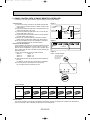
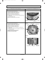
1. SPACE-SAVING CENTRALLY LOCATED CEILING RECESSED INSTALLATION
2. 4-WAY AIR FLOW SYSTEM
This series allows you to select from 2, 3, and 4 way air flow directions according to your requirement. As a result, you get
superb flexibility in choosing a configuration that gives you maximum cooling/heating efficiency in a neat and unobstructive
installation.
3. STABLE COOLING EVEN AT OUTDOOR TEMPERATURES AS LOW AS 0--F MAKES
YEAR-ROUND AIR-CONDITIONING POSSIBLE
The microprocessor automatically adjusts fan speed in accordance with outdoor temperature to maintain the coolant at an
even condensing temperature. The result is smooth, efficient cooling even when temperatures outdoors drop as low as 0-F.
This makes the unit ideal for a wide range of specialized cooling needs, such as rooms with many office machines or computers and areas subject to strong sunlight.
4. ADVANCED MICROPROCESSOR CONTROL
(1) Easy to use Microprocessor (remote controller)
1) Ultra-Thin Remote Controller
The streamlined, wide controller is designed to blend with any kind of interior and the adoption of a sophisticated microprocessor allows you to carry out a wide range of operations easily.
2) Attractive Liquid Crystal Display (LCD)
Units operation mode, set temperature, room temperature, timer setting, fan speed, and air flow direction are displayed
on the remote controller with the easily understood visual Liquid Crystal Display (LCD).
3) Convenient 24-Hour ON-OFF Timer
The timer allows Mr.SLIM to be switched on or off automatically at the time is shown on the LCD.
4) Self-Diagnostic Feature Indicates Faults Instantly
In the rare case when a problem occurs, the unit stops operating and the set temperature indicator changes to the selfdiagnostic indicator, indicating the location of the fault.
If the check switch is pressed twice, the unit stops operating and the check mode is initiated. The cause of the most
recent problem stored in the memory is displayed on the LCD. This is extremely useful for maintenance purposes.
5) Useful Memory Feature for Storing Instructions
The previous set value is memorized so that constant temperature control can be obtained. This is convenient when,
for example, a power failure occurs.
(2) Non-polar Two-Wire Remote Controller Cables
The non-polar, two-wire type remote controller cable is slim, installation is simple and trouble-free. Remote controller wire
can be extended up to 550 yards.
OC244-2
Oc244--1.qxd
7/16/2001
4:12 PM
Page 3
(3) Automatic Cooling/Heating Changeover Operation
An automatic cooling and heating changeover operation system is provided to ensure easy control and year-round air conditioning.
Once the desired temperature is set, unit operation is switched automatically between cooling and heating, in accordance
with the room temperature. In addition, the use of outdoor unit fan speed controller enables cooling operation at outdoor
temperature as low as 0-F.
5. DRAIN PUMP FOR EASY PIPE CONNECTION (DRAIN LIFT-UP MECHANISM)
This mechanism, with its capacity to raise drain water 33-7/16 inch above the ceiling line, is convenient for removing water
and avoiding piping contact with beams, etc.
6. FRESH AIR INTAKE AND BRANCH DUCTING ARE AVAILABLE (on-site work)
7. REDI-CHARGED REFRIGERANT SYSTEM
The industry is first redi-charge refrigerant system.
There is no need to adjust the amount of refrigerant to match the piping length on-site unless lines exceed 100feet.
You will see a major reduction in installation time and labor costs.
8. HIGH RELIABILITY AND EASY SERVICING.
In addition to the self-diagnostic function, units are also equipped with a 3-minute time delay mechanism (cooling), an auto
restart function, an emergency operation function, a test run switch, etc., to assure high reliability and easy servicing.
9. NITROGEN GAS IS CHARGED TO INDOOR UNIT.
Indoor unit and refrigerant pipes are charged with nitrogen gas (N2) instead of (R22) before shipment from the factory.
OC244-3
Oc244--1.qxd
2
7/16/2001
4:12 PM
Page 4
PART NAMES AND FUNCTIONS
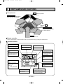
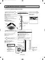
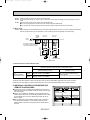
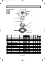
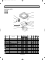
● Indoor (Main) Unit
Filter
Remove dust and pollutants
from return air
Horizontal Air Outlet
Sets airflow horizontal automatically
during cooling or dehumidifying.
Grille
Auto Air Swing Vane
Disperses airflow up and
down and adjusts the angle
of airflow direction.
Air Intake
Returns air from room.
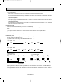
● Remote controller
On the controls are set, the same operation mode can be repeated by simply pressing the ON/OFF button.
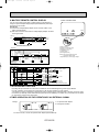
● Operation buttons
TIMER ON/OFF button
This switches between continuous
operation and the timer operation.
CLOCK/TIMER button
FAN SPEED button
This sets or switches the current
time,start time and stop time.
This sets the ventilation fan speed.
ON/OFF button
OPERATION MODE
button
This switches between the operation and stop modes each time it is
press. The lamp on this button
lights during operation.
Press this button to switch the cooling,electronic dry (Dehumidify),automatic and heating modes.
SWING
DRY COOL TIMER OFF TIMER CLOCK AUTO AUTO
AUTO
CHECK SET TEMP.
START STOP FAN
SPEED
HEAT
SET TEMPERATURE
button
This sets the room temperature.
The temperature setting can be performed in 2-F units.
Setting range :
Cooling 65-F to 87-F
Heating 61-F to 83-F
MODE
F
AIR DISCHARGE
button
AUTO
RETURN
TIMER ON/OFF CLOCK/TIMER FAN SPEED AIR DISCHARGE FILTER
AIR SWEEP
SET TEMP.
TIMER SET
This adjusts the vertical angle of the
vane.
CHECK
TEST RUN
REMOTE CONTROLLER
PAR-JH241KUS
FILTER button
This resets the filter service indication display.
CHECK-TEST RUN button
AIR SWEEP button
This switches the horizontal louver
motion ON and OFF.
Press twice this button to perform an
inspection check or test operation.
Do not use it for normal operation.
(Not available for this model.)
OC244-4
Oc244--1.qxd
7/16/2001
4:12 PM
Page 5
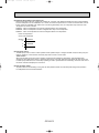
● Display
CENTRALLY
CONTROLLED display
This indicates when the unit is controlled by optional features such as
central control type remote controller.
In this display example on the bottom left, a condition where all display lamps light is shown for
explanation purposes although this differs from
actual operation.
CLOCK display
The current time , start time and stop
time can be displayed in ten second
intervals by pressing the time switch
button. The start time or stop time is
always displayed during the timer
operation.
AIR DISCHARGE display
This displays the air direction.
TIMER
display
FAN SPEED display
This indicates when the continuous
operation and time operation modes
are set.
It also display the time for the timer
operation at the same time as when
it is set.
The selected fan speed is displayed.
display
SWING
OPERATION MODE display
DRY COOL TIMER OFF TIMER CLOCK AUTO AUTO
AUTO
CHECK SET TEMP.
START STOP FAN
SPEED
HEAT
F
AUTO
RETURN
This indicates the operation mode.
MODE
TIMER ON/OFF CLOCK/TIMER FAN SPEED AIR DISCHARGE FILTER
STANDBY display
This indicates when the standby
mode is set from the time the heat
operation starts until the heating air
is discharged.
AIR SWEEP
SET TEMP.
TIMER SET
CHECK
TEST RUN
REMOTE CONTROLLER
PAR-JH241KUS
CHECK MODE
TEST RUN
This indicates when the defrost operation is performed.
display
This indicates when a malfunction
has occurred in the unit which should
be checked.
Operation lamp
This lamp lights during operation,
goes off when the unit stops and
flashes when a malfunction occurs.
DEFROST display
CHECK
The temperature of the return air is
displayed during operation. The display range is 47° to 97°F. The display flashes 47°F when the actual
temperature is less than 47° and
flashes 97°F when the actual temperature is greater than 97°F.
display
This display lights in the check mode
or when a test operation is performed.
display
display
FILTER
This displays the selected setting
temperature.
This lamp lights when electricity is
supplied to the unit.
display
This lamp lights when the filter needs
to be cleaned.
Caution
● Only the
display lights when the unit is stopped and power supplied to the unit.
● When power is turned ON for the first time the (CENTRAL CTRL) display appears to go on momentarily but this is not a malfunction.
● When the central control remote control unit, which is sold separately, is used the ON-OFF button,OPERATION MODE button and SET
TEMP button do not operate.
● “NOT AVAILABLE” is displayed when the AIR SWEEP button are pressed.
(AIR SWEEP function is not provided for PLH series.)
OC244-5
Oc244--1.qxd
3
7/16/2001
4:12 PM
Page 6
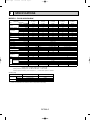
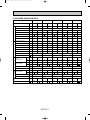
SPECIFICATIONS
MODELS : PLH18/24/30/36/42AK
Model
PLH18AK
PLH24AK
PLH30AK
PLH36AK
PLH42AK
Item
Btu/h
Cooling *1
35,400
24,000
18,000
30,000
42,000
Heating *1, *3 Btu/h 19,000(24,500/25,500) 26,000(31,500/32,500) 33,000(39,500/41,200) 38,000(45,900/47,600) 44,300(52,200/53,900)
Heating *2, *3 Btu/h 11,000(16,500/17,500) 16,500(22,000/23,000) 18,500(25,000/26,700) 23,000(30,900/32,600) 26,800(34,700/36,400)
Pints/h
Moisture removal
10.9
7.0
5.3
9.1
12.3
kW
Cooling *1
3.63
2.57
1.75
3.17
3.98
Power
Heating *1, *3 kW
3.45(5.75/6.25)
2.51(4.11/4.41)
1.59(3.19/3.49)
3.04(4.94/5.44)
3.82(6.12/6.62)
Consumption
Heating *2, *3 kW
2.93(5.23/5.73)
2.15(3.75/4.05)
1.32(2.92/3.22)
2.55(4.45/4.95)
3.24(5.54/6.04)
*1
EER
9.8
9.3
10.3
9.5
10.6
SEER
10.0
10.3
10.5
10.4
10.7
HSPF
7.1
7.0
7.2
6.9
7.0
*1
3.2
3.0
3.5
3.2
3.4
COP
*2
2.3
2.2
2.4
2.1
2.4
INDOOR UNIT MODELS
PLH36AK
PLH24AK
PLH18AK
PLH30AK
PLH42AK
External finish
Galvanized sheets with gray heat insulation
V,phase,Hz
Power supply
208/230,1,60
20
A
Max.fuse size (time delay)
25
15
A
Min.ampacity
17
1.2
1.4
F.L.A.
Fan motor
0.7
7.7/8.3(1.6/1.9)
11.1/12.2(2.3/2.8)
A(kW)
Booster heater
9.1/10.4(1.9/2.4)
CFM
Dry
1060-780
990-710
710-530
Airflow Hi-Lo
CFM
Wet
1020-740
950-670
670-490
45-37
dB
Sound level Hi-Lo
41-33
37-31
43-35
in.
Unit drain pipe O.D.
1-1/4
in.
W
33-1/16
in.
D
Dimensions
33-1/16
11-3/4
in.
H
10-3/16
71
75
lb
Weight
57
External finish
Munsell 0.7Y 8.59/0.97
in.
W
37-3/8
in.
37-3/8
Dimensions D
in.
H
1-3/16
lb
Weight
11
OUTDOOR UNIT MODELS
PUH36EK1
PUH24EK
PUH18EK
PUH30EK1
PUH42EK7
INDOOR GRILLE
Capacity
NOTES : *1.Rating conditions (cooling)-indoor : 80˚FDB,67˚FWB outdoor : 95˚FDB,75˚FWB.
(heating)-indoor : 70˚FDB,60˚FWB outdoor : 47˚FDB,43˚FWB.
*2.Rating conditions (heating)-indoor : 70˚FDB,60˚FWB outdoor : 17˚FDB,15˚FWB.
*3.Heating capacity and Heating power consumption in ( ) includes heater operation at 208/230V.
Operating range
Cooling
Heating
*
Maximum
Minimum
Maximum
Minimum
Indoor intake air temperature
Outdoor intake air temperature
95˚FDB,71˚FWB
67˚FDB,57˚FWB
80˚FDB,67˚FWB
70˚FDB,60˚FWB
115˚FDB
0˚FDB*
75˚FDB,65˚FWB
17˚FDB,15˚FWB
In case of the wind baffle is installed.
(In case of the wind baffle is not installed, the minimum temperature will be 23˚FDB.)
OC244-6
Oc244--1.qxd
7/16/2001
4
4:12 PM
Page 7
DATA
MODELS : PLH18/24/30/36/42AK
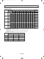
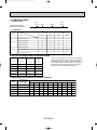
1. PERFORMANCE DATA
1) COOLING CAPACITY
Indoor air
Models
Airflow
(CFM)
B.F
PLH42AK
85
95
105
115
TC
SHC TPC
SHC
TPC
TC
21.4
14.4 1.45
20.9 14.1
1.53
20.3
13.6
1.64
19.4 13.0
1.80 18.4
12.4
1.96
17.6
11.8
2.10
67
20.1
16.3 1.42
19.5 15.8
1.49
18.9
15.3
1.60
18.0 14.6
1.75 17.1
13.8
1.90
16.3
13.2
2.02
63
18.8
17.7 1.39
18.2 17.2
1.46
17.6
16.6
1.57
16.8 15.8
1.70 15.9
15.0
1.84
15.1
14.2
1.96
DB 75-F (50%RH)
62.5
18.6
15.9 1.39
18.1 15.4
1.46
17.4
14.9
1.59
16.6 14.1
1.70 15.7
13.4
1.84
14.9
12.7
1.95
DB 72-F (50%RH)
60
17.9
15.2 1.37
17.3 14.7
1.44
16.7
14.2
1.54
15.9 13.5
1.67 15.1
12.8
1.81
14.3
12.1
1.92
DB 70-F (50%RH)
59
17.6
14.9 1.36
17.0 14.4
1.43
16.4
13.9
1.53
15.6 13.2
1.66 14.8
12.5
1.79
14.0
11.8
1.90
71
28.5
19.2 2.13
27.9 18.8
2.24
27.0
18.2
2.41
25.8 17.4
2.64 24.6
16.5
2.88
23.5
15.8
3.08
67
26.8
21.7 2.09
26.0 21.1
2.19
25.2
20.4
2.35
24.0 19.4
2.57 22.8
18.5
2.79
21.7
17.6
2.97
63
25.1
23.6 2.05
24.3 22.9
2.14
23.5
22.1
2.30
22.4 21.1
2.50 21.2
19.9
2.71
20.1
19.0
2.88
DB 75-F (50%RH)
62.5
24.8
21.1 2.04
24.1 20.5
2.14
23.2
19.8
2.29
22.1 18.9
2.49 21.0
17.9
2.70
19.9
17.0
2.87
DB 72-F (50%RH)
60
23.8
20.3 2.02
23.1 19.6
2.11
22.3
19.0
2.26
21.2 18.0
2.46 20.1
17.1
2.65
19.1
16.2
2.82
DB 70-F (50%RH)
59
23.4
19.8 2.00
22.7 19.2
2.10
21.9
18.5
2.24
20.8 17.6
2.44 19.7
16.6
2.63
18.7
15.8
2.79
71
35.7
22.6 2.63
34.9 22.1
2.76
33.8
21.4
2.97
32.3 20.4
3.26 30.7
19.4
3.55
29.3
18.5
3.81
67
33.4
25.8 2.58
32.6 25.1
2.70
31.5
24.2
2.90
30.0 23.1
3.17 28.5
21.9
3.44
27.1
20.9
3.66
670
0.14
950
0.09
PLH24AK
PLH36AK
IWB
(˚F)
71
PLH18AK
PLH30AK
Outdoor intake air DB temperature(˚F)
75
65
1020
0.14
TC
SHC TPC
TC
SHC TPC
TC
SHC
TPC
TC
SHC TPC
63
31.3
28.2 2.53
30.4 27.4
2.64
29.3
26.5
2.84
27.9 25.2
3.09 26.5
23.9
3.34
25.2
22.7
3.55
DB 75-F (50%RH)
62.5
31.0
25.2 2.52
30.1 24.4
2.64
29.1
23.6
2.83
27.7 22.5
3.08 26.2
21.3
3.33
24.9
20.2
3.54
DB 72-F (50%RH)
60
29.8
24.1 2.49
28.9 23.4
2.60
27.9
22.6
2.79
26.5 21.5
3.03 25.1
20.3
3.27
23.8
19.3
3.48
DB 70-F (50%RH)
59
29.3
23.6 2.47
28.4 22.9
2.59
27.4
22.0
2.77
26.0 21.0
3.01 24.6
19.8
3.25
23.3
18.8
3.44
71
42.1
25.3 3.02
41.2 24.8
3.16
39.9
24.0
3.41
38.1 22.9
3.73 36.2
21.8
4.07
34.6
20.8
4.36
67
39.5
29.2 2.95
38.4 28.4
3.09
37.1
27.5
3.33
35.4 26.2
3.63 33.6
24.9
3.94
32.0
23.7
4.20
1020
0.06
63
37.0
32.2 2.89
35.9 31.3
3.03
34.6
30.2
3.25
33.0 28.8
3.54 31.2
27.2
3.82
29.7
25.9
4.07
DB 75-F (50%RH)
62.5
36.6
28.6 2.88
35.5 27.8
3.02
34.3
26.8
3.24
32.7 25.5
3.52 30.9
24.2
3.81
29.4
23.0
4.05
DB 72-F (50%RH)
60
35.2
27.4 2.85
34.1 26.6
2.98
32.9
25.7
3.19
31.3 24.4
3.47 29.6
23.1
3.75
28.1
21.9
3.98
DB 70-F (50%RH)
59
34.6
26.8 2.83
33.5 26.0
2.96
32.3
25.0
3.17
30.7 23.8
3.44 29.0
22.5
3.72
27.5
21.4
3.94
71
50.0
27.6 3.31
48.9 27.0
3.47
47.3
26.1
3.73
45.2 24.9
4.09 43.0
23.7
4.46
41.1
22.7
4.78
67
46.8
32.3 3.24
45.6 31.4
3.39
44.0
30.4
3.65
42.0 29.0
3.98 39.9
27.5
4.32
38.0
26.2
4.60
63
43.8
36.0 3.17
42.6 35.0
3.32
41.1
33.8
3.56
39.1 32.2
3.88 37.1
30.5
4.19
35.2
29.0
4.46
DB 75-F (50%RH)
62.5
43.4
31.8 3.16
42.1 30.9
3.31
40.7
29.8
3.55
38.7 28.4
3.86 36.7
26.9
4.18
34.9
25.5
4.44
DB 72-F (50%RH)
60
41.7
30.5 3.12
40.4 29.5
3.27
39.0
28.5
3.50
37.1 27.1
3.80 35.1
25.6
4.11
33.3
24.3
4.36
DB 70-F (50%RH)
59
41.0
29.8 3.10
39.7 28.8
3.25
38.3
27.8
3.48
36.4 26.4
3.78 34.4
25.0
4.07
32.7
23.7
4.32
1020
0.06
Notes 1. B.F. : Bypass Factor, IWB : Intake air wet-bulb temperature
TC : Total Capacity (x103 Btu/h), SHC : Sensible Heat Capacity (x103 Btu/h)
TPC : Total Power Consumption (kW)
2. SHC is based on 80˚FDB of indoor intake air temperature.
3. Cooling capacity correction factors and Refrigerant piping length (one way) range.
Refrigerant piping length (one way)
MODEL
25ft
40ft
55ft
70ft
85ft
100ft
115ft
130ft
PLH18AK
1.0
0.992
0.983
0.978
0.966
0.959
0.950
0.945
PLH24AK
1.0
0.981
0.968
0.952
0.940
0.925
0.913
PLH30AK
1.0
0.981
0.968
0.952
0.940
0.925
PLH36AK
1.0
0.981
0.968
0.952
0.940
PLH42AK
1.0
0.975
0.955
0.935
0.918
150ft
164ft
0.900
0.886
0.874
0.913
0.900
0.886
0.874
0.925
0.913
0.900
0.886
0.874
0.900
0.884
0.869
0.855
0.840
OC244-7
Oc244--1.qxd
7/16/2001
4:12 PM
Page 8
2) HEATING CAPACITY
Indoor air
Models
PLH18AK
PLH24AK
PLH30AK
PLH36AK
PLH42AK
Airflow
(CFM)
710
990
1060
1060
1060
IDB
(˚F)
Auxiliary heater
208V
230V
Outdoor intake air WB temperature(˚F)
15
25
35
45
55
65
CA
PC
CA
PC
CA
PC
CA
PC
CA
PC
CA
PC
CA
PC
75
12.5
1.23
14.4
1.36
16.8
1.53
19.1
1.68
22.0
1.87
24.7
2.04
5.5
1.6
70
12.8
1.19
14.7
1.32
17.2
1.48
19.5
1.62
22.4
1.80
25.0
1.96
65
13.1
1.15
15.0
1.27
17.6
1.42
19.9
1.56
22.9
1.73
25.5
1.88
6.5
1.9
75
17.1
1.94
19.7
2.15
23.0
2.42
26.1
2.66
30.1
2.95
33.7
3.21
5.5
1.6
70
17.5
1.88
20.1
2.08
23.5
2.33
26.6
2.56
30.7
2.84
34.2
3.09
65
17.9
1.81
20.6
2.00
24.1
2.24
27.2
2.45
31.3
2.73
34.9
2.97
6.5
1.9
75
21.8
2.36
25.0
2.16
29.2
2.93
33.1
3.22
38.2
3.58
42.8
3.89
6.5
1.9
70
22.2
2.28
25.5
2.52
29.9
2.82
33.8
3.10
38.9
3.44
43.5
3.74
8.2
2.4
65
22.8
2.19
26.1
2.42
30.5
2.71
34.5
2.97
39.7
3.30
44.3
3.59
75
25.0
2.67
28.7
2.96
33.7
3.33
38.1
3.65
44.0
4.06
49.3
4.42
7.8
2.3
70
25.6
2.58
29.4
2.86
34.4
3.20
38.9
3.51
44.8
3.90
50.0
4.25
9.6
2.8
65
26.2
2.49
30.1
2.75
35.2
3.08
39.8
3.37
45.7
3.75
51.0
4.08
75
29.2
2.96
33.5
3.28
39.2
3.68
44.5
4.04
51.3
4.49
57.5
4.89
7.8
2.3
70
29.9
2.86
34.3
3.16
40.1
3.55
45.4
3.89
52.2
4.32
58.3
4.70
9.6
2.8
65
30.6
2.75
35.1
3.04
41.0
3.41
46.3
3.74
53.3
4.15
59.5
4.52
Notes 1. IDB : Intake air dry-bulb temperature
CA : Capacity (x103 Btu/h), PC : Power Consumption (kW)
2. When booster heater is "on", total capacity and total power consumption should be added the figures described in
booster heater column.
•Booster heater ON : When the set temperature is higher than the room temperature by more than 5.4 deg.
•Booster heater OFF : When the set temperature is higher than the room temperature by less than 3.6 deg.
3. Heating capacity correction factors.
Refrigerant piping length (one way)
Models
Less than 100ft
100~130ft
130~164ft
PLH18AK
1.00
0.995
0.990
PLH24AK
1.00
0.995
0.990
PLH30AK
1.00
0.995
0.990
PLH36AK
1.00
0.995
0.990
PLH42AK
1.00
0.995
0.990
OC244-8
Oc244--1.qxd
7/16/2001
4:12 PM
Page 9
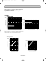
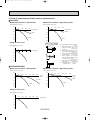
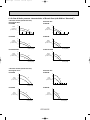
2. PERFORMANCE CURVE
NOTES : A point on the curve shows the reference point.
PLH18AK COOLING CAPACITY
SHF=0.81
Indoor intake air WB temperature ( F)
18
71
67
63
Total capacity (x10 3 Btu/h)
24
Does not include booster heater (1.9kW)
30
12
Indoor intake air DB temperature ( F)
18
2.5
71
67
63
2.0
1.5
Indoor intake air WB temperature ( F)
1.0
023
32 35
45
55
65(67) 75
85
95
105
2.5
75
70
65
2.0
1.5
Indoor intake air DB temperature ( F)
1.0
15
115
Outdoor intake air DB temperature ( F)
45
55
65
30
24
71
67
63
Indoor intake air WB temperature ( F)
Does not include booster heater (1.9kW)
36
18
Total capacity (x10 3 Btu/h)
Total capacity (x10 3 Btu/h)
35
PLH24AK HEATING CAPACITY
SHF=0.81
36
25
Outdoor intake air WB temperature ( F)
PLH24AK COOLING CAPACITY
12
Indoor intake air DB temperature ( F)
65
70
75
30
24
18
12
71
67
63
3.0
2.5
2.0
Indoor intake air WB temperature ( F)
1.5
023
32 35
45
55
65(67) 75
85
95 105
Outdoor intake air DB temperature ( F)
115
OC244-9
Total power consumption (kW)
Total power consumption (kW)
65
70
75
24
12
Total power consumption (kW)
Total capacity (x10 3 Btu/h)
30
Total power consumption (kW)
PLH18AK HEATING CAPACITY
75
70
65
3.0
2.5
2.0
Indoor intake air DB temperature ( F)
1.5
15
25
35
45
55
Outdoor intake air WB temperature ( F)
65
Oc244--1.qxd
7/16/2001
4:12 PM
Page 10
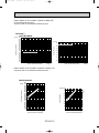
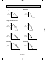
NOTES : A point on the curve shows the reference point.
PLH30AK COOLING CAPACITY
SHF=0.77
48
Total capacity(x10 3 Btu/h)
Total capacity(x10 3 Btu/h)
42
36
30
indoor intake air WB temperature(-F)
4.0
Total power consumption(kW)
71
67
63
24
71
67
63
3.5
3.0
2.5
2.0
indoor intake air WB temperature(-F)
0 23 32 35 45
55 65 (67) 75
85
95 105
Outdoor intake air DB temperature(-F)
36
30
24
18
4.0
3.0
2.5
2.0
indoor intake air DB temperature(-F)
71
67
63
71
67
63
4.0
3.5
3.0
2.5
indoor intake air WB temperature(-F)
0 23 32 35 45
55 65 (67) 75
85
95 105
Outdoor intake air DB temperature(-F)
115
Total capacity(x10 3 Btu/h)
54
Total power consumption(kW)
Total capacity(x10 Btu/h)
Total power consumption(kW)
4.5
25
35
45
55
65
Outdoor intake air WB temperature(-F)
36
indoor intake air WB temperature(-F)
75
70
65
3.5
15
42
30
65
70
75
indoor intake air DB temperature(-F)
115
SHF=0.74
48
Does not include booster heater(2.4kW)
42
PLH36AK COOLING CAPACITY
3
Total power consumption(kW)
PLH30AK HEATING CAPACITY
PLH36AK HEATING CAPACITY
Does not include booster heater(2.8kW)
indoor intake air DB temperature(-F)
48
65
70
75
42
36
30
24
4.5
75
70
65
4.0
3.5
3.0
2.5
indoor intake air DB temperature(-F)
2.0
15
25
35
45
55
Outdoor intake air WB temperature(-F)
OC244-10
65
Oc244--1.qxd
7/16/2001
4:12 PM
Page 11
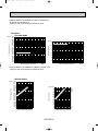
NOTES : A point on the curve shows the reference point.
PLH42AK COOLING CAPACITY
SHF=0.69
48
42
71
67
63
36
indoor intake air WB temperature(-F)
71
67
63
4.5
4.0
3.5
3.0
2.5
indoor intake air WB temperature(-F)
0 23 32 35 45
55 65 (67) 75
85
95 105
Outdoor intake air DB temperature(-F)
115
OC244-11
Total capacity(x10 3 Btu/h)
60
Total power consumption(kW)
Total power consumption(kW)
Total capacity(x10 3 Btu/h)
54
PLH42AK HEATING CAPACITY
Does not include booster heater(2.8kW)
indoor intake air DB temperature(-F)
54
65
70
75
48
42
36
30
75
70
65
4.5
4.0
3.5
3.0
2.5
indoor intake air DB temperature(-F)
15
25
35
45
55
Outdoor intake air WB temperature(-F)
65
Oc244--1.qxd
7/16/2001
4:12 PM
Page 12
3. CONDENSING PRESSURE AND SUCTION PRESSURE
Data is based on the condition of indoor humidity 50%.
Air flow should be set at HI.
A point on the curve shows the reference point.
<PLH18AK>
COOLING MODE
86
80
100
75 (psi.G)
70
90
Suction pressure
Condensing pressure
(psi.G) 350
340
330
320
310
300
290
280
270
260
250
240
230
220
210
200
190
180
170
160
150
80
86
80
75
70
Indoor DB temperature( F)
70
60
50
40
Indoor DB
temperature( F)
30
30
40
50
60
70
80
90
Outdoor ambient temperature
100
110
DB( F)
20
30
40
50
60
70
80
90
Outdoor ambient temperature
100
Data is based on the condition of outdoor humidity 75%.
A point on the curve shows the reference point.
HEATING MODE
(psi.G) 350
340
330
320
310
300
290
280
270
260
)
(F
250
re
u
75
t
240
ra
70
230
pe
m
65
220
te
B
210
D
or
200
do
190 In
180
170
160
150
20 25 30 35 40 45 50 55 60 65 70
DB( F)
Outdoor ambient temperature
80
ur
e(
F
)
Condensing pressure
(psi.G)
ra
t
75
70
65
te
m
pe
60
40
do
or
DB
50
In
Suction pressure
70
30
20
10
20 25 30 35 40 45 50 55 60 65 70
DB( F)
Outdoor ambient temperature
OC244-12
110
DB( F)
Oc244--1.qxd
7/16/2001
4:12 PM
Page 13
Data is based on the condition of indoor humidity 50%.
Air flow should be set at HI.
A point on the curve shows the reference point.
<PLH24AK>
COOLING MODE
Suction pressure
86
80 (psi.G) 100
75
70
90
Condensing pressure
360
(psi.G) 350
340
330
320
310
300
290
280
270
260
250
240
230
220
210
200
190
180
170
160
150
Indoor DB
temperature( F)
86
80
75
70
Indoor DB temperature( F)
80
70
60
50
40
30
30
40
50
60
70
80
90
Outdoor ambient temperature
100
110
DB( F)
20
30
40
50
60
70
80
90
Outdoor ambient temperature
100
Data is based on the condition of outdoor humidity 75%.
A point on the curve shows the reference point.
HEATING MODE
OC244-13
e(
F)
(psi.G) 80
75
70
65
pe
ra
tu
r
70
te
m
60
40
do
or
DB
50
In
Suction pressure
Condensing pressure
(psi.G) 350
340
330
320
310
300
290
F)
280
e(
ur
t
270
ra
pe
260
m
te
250
75
B
240
rD
70
o
o
230 nd
65
I
220
210
200
190
180
170
160
150
20 25 30 35 40 45 50 55 60 65 70
DB( F)
Outdoor ambient temperature
30
20
10
20 25 30 35 40 45 50 55 60 65 70
DB( F)
Outdoor ambient temperature
110
DB( F)
Oc244--1.qxd
7/16/2001
4:12 PM
Page 14
Data is based on the condition of indoor humidity 50%.
Air flow should be set at HI.
A point on the curve shows the reference point.
<PLH30AK>
COOLING MODE
(psi.G) 350
340
330
320
310
300
290
280
270
260
250
240
230
220
210
200
190
180
170
160
150
Suction pressure
Condensing pressure
86 (psi.G) 110
80
100
75
70
90
Indoor DB temperature( F)
86
80
75
70
Indoor DB temperature( F)
80
70
60
50
40
30
40
50
60
70
80
90
Outdoor ambient temperature
100
110
DB( F)
30
30
40
50
60
70
80
90
Outdoor ambient temperature
100
Data is based on the condition of outdoor humidity 75%.
A point on the curve shows the reference point.
HEATING MODE
(psi.G) 340
330
320
310
300
290
280
F)
e(
270
r
tu
260
ra
pe
75
250
m
te
70
240
B
65
D
230
r
oo
220
d
210 In
200
190
180
170
160
150
140
20 25 30 35 40 45 50 55 60 65 70
DB( F)
Outdoor ambient temperature
(F
)
(psi.G) 80
m
pe
ra
tu
re
Condensing pressure
70
te
or
D
do
40
B
50
In
Suction pressure
60
75
70
65
30
20
10
20 25 30 35 40 45 50 55 60 65 70
DB( F)
Outdoor ambient temperature
OC244-14
110
DB( F)
Oc244--1.qxd
7/16/2001
4:12 PM
Page 15
Data is based on the condition of indoor humidity 50%.
Air flow should be set at HI.
A point on the curve shows the reference point.
<PLH36AK >
COOLING MODE
(psi.G)
90
Indoor DB temperature( F)
86
80
75
70
Indoor DB temperature(-F)
80
Suction pressure
86
80
75
70
Condensing pressure
(psi.G) 350
340
330
320
310
300
290
280
270
260
250
240
230
220
210
200
190
180
170
160
150
70
60
50
40
30
20
30
40
50
60
70
80
90
Outdoor ambient temperature
100
110
DB( F)
30
40
50
60
70
80
90
Outdoor ambient temperature
100
Data is based on the condition of outdoor humidity 75%.
A point on the curve shows the reference point.
HEATING MODE
OC244-15
ur
e(
F
)
(psi.G) 80
pe
ra
t
70
75
70
65
te
m
60
or
40
DB
50
In
do
Suction pressure
Condensing pressure
(psi.G) 350
340
330
320
310
)
(F
300
re
u
t
290
ra
pe
280
m
te
270
DB
260
r
75
o
250
70
do
240 In
65
230
220
210
200
190
180
170
160
150
20 25 30 35 40 45 50 55 60 65 70
DB( F)
Outdoor ambient temperature
30
20
10
20 25 30 35 40 45 50 55 60 65 70
DB( F)
Outdoor ambient temperature
110
DB( F)
Oc244--1.qxd
7/16/2001
4:12 PM
Page 16
Data is based on the condition of indoor humidity 50%.
Air flow should be set at HI.
A point on the curve shows the reference point.
<PLH42AK >
COOLING MODE
86
80
75
70
(psi.G)
90
86
80
75
70
Indoor DB temperature(-F)
Condensing pressure
80
Suction pressure
(psi.G) 350
340
330
320
310
300
290
280
270
260
250
240
230
220
210
200
190
180
170
160
150
Indoor DB temperature( F)
70
60
50
40
30
20
30
40
50
60
70
80
90
Outdoor ambient temperature
100
30
110
DB( F)
40
50
60
70
80
90
Outdoor ambient temperature
Data is based on the condition of outdoor humidity 75%.
A point on the curve shows the reference point.
HEATING MODE
(F
)
(psi.G) 80
pe
ra
tu
re
70
75
70
65
te
m
60
do
o
40
rD
B
50
In
Suction pressure
Condensing pressure
(psi.G) 350
340
330
320
310
F)
300
e(
r
tu
290
ra
pe
280
m
te
270
75
DB
260
70
r
o
250
65
do
n
240 I
230
220
210
200
190
180
170
160
150
20 25 30 35 40 45 50 55 60 65 70
DB( F)
Outdoor ambient temperature
30
20
10
20 25 30 35 40 45 50 55 60 65 70
DB( F)
Outdoor ambient temperature
OC244-16
100
110
DB( F)
Oc244--1.qxd
7/16/2001
4:12 PM
Page 17
4. STANDARD OPERATION DATA
Models
PLH18AK
Refrigerant circuit
Electrical circuit
Item
Indoor side
PLH36AK
PLH42AK
Cooling
Heating
Cooling
Heating
Cooling
Heating
Cooling
Heating
Cooling
Heating
Voltage
V
208/230
208/230
208/230
208/230
208/230
208/230
208/230
208/230
208/230
208/230
Frequency
Hz
Total input
kW
1.75
1.59
2.57
2.51
3.17
3.04
3.63
3.45
3.98
3.82
Indoor fan current
A
0.7
0.7
1.2
1.2
1.2
1.2
1.4
1.4
1.4
1.4
Booster heater current
A
Outdoor fan current
A
0.75
0.75
Comp. current
A
7.5/7.0
6.5/6.3
9.9/9.1
9.5/8.8
12.8/12.1
12.2/11.6
14.5/13.4
Condensing pressure
psi·G
246
218
240
228
239
223
Suction pressure
psi·G
76
57
83
62
77
Discharge temperature
˚F
192
150
170
155
Condensing temperature
˚F
116
107
114
Suction temperature
˚F
70
34
Comp.shell bottom temperature
˚F
189
145
Ref. pipe length
ft
Intake
air temperature
Outdoor side
PLH30AK
Unit
Refrigerant charge
Discharge
air temperature
60
60
7.7/8.3
60
7.7/8.3
60
9.1/10.4
60
11.1/12.2
0.65+0.65 0.65+0.65 0.75+0.75 0.75+0.75 0.75+0.75 0.75+0.75
11.1/12.2
0.8+0.8
0.8+0.8
13.6/12.8
16.5/15.6
16.1/14.9
240
233
257
242
58
81
59
76
57
162
155
166
163
164
153
112
114
109
114
112
119
115
53
36
49
34
51
35
46
32
156
135
152
142
155
147
110
76
25
25
25
25
25
5 lbs 8 oz
9 lbs 15 oz
10 lbs 2 oz
10 lbs 9 oz
11 lbs 0 oz
DB
˚F
80
70
80
70
80
70
80
70
80
70
WB
˚F
67
60
67
60
67
60
67
60
67
60
DB
˚F
60
96
59
96
59
101
57
106
54
112
WB
˚F
59
58
58
56
54
Fan speed
r.p.m.
530
640
690
790
790
Airflow (High)
CFM
710
990
1,060
1,060
1,060
Intake
air temperature
DB
˚F
WB
˚F
95
47
95
47
43
95
47
43
95
47
43
95
47
43
43
Fan speed upper/lower
r.p.m.
790
750/750
760/760
760/760
840/840
Airflow
CFM
1,590
3,170
3,350
3,350
3,530
Capacity
SHF
PLH24AK
Btu/h
18,000
0.81
19,000
24,000
26,000
0.81
OC244-17
30,000
0.77
33,000
35,400
0.74
38,000
42,000
0.69
44,300
Oc244--1.qxd
7/16/2001
4:12 PM
Page 18
5. OPERATING RANGE
1) POWER SUPPLY
Min.
198V
1 Phase 60Hz 208/230V
Guaranteed voltage range
208V
Max.
253V
230V
2) OPERATION
Air intake temperature
Indoor
Outdoor
Function
Condition
DB(˚F)
WB(˚F)
DB(˚F)
WB(˚F)
Standard temperature
80
67
95
75
Maximum temperature
95
71
115
—
Minimum temperature
67
57
0
—
Maximum humidity
80
75
80
75
Standard temperature
70
60
47
43
Maximum temperature
80
67
75
65
Minimum temperature
70
60
17
15
Cooling
Heating
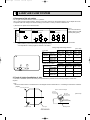
6. OUTLET AIR SPEED AND COVERAGE RANGE
Model
Airflow
(CFM)
Air speed
(ft/sec)
Coverage
range(ft)
PLH18AK
710
13.1
19
PLH24AK
990
16.1
24
PLH30AK
1,060
17.1
26
PLH36AK
1,060
21.7
29
PLH42AK
1,060
21.7
29
The air coverage range is the value up to the position
where the air speed is 0.8ft/sec. when air is blown out
horizontally from the unit at the High notch position.
The coverage range should be used only as a general
guideline since it varies according to the size of the
room and furniture installed inside the room.
7. ADDITIONAL REFRIGERANT CHARGE (R22(oz))
25ft
40ft
55ft
70ft
85ft
100ft
115ft
130ft
150ft
164ft
PLH18AK
Outdoor unit
precharged
(up to 100ft)
5 lbs 8 oz
0
0
0
0
0
0
2
4
—
—
PLH24AK
9 lbs 15 oz
0
0
0
0
0
0
2
4
7
9
PLH30AK
10 lbs 2 oz
0
0
0
0
0
0
5
10
16
20
PLH36AK
10 lbs 9 oz
0
0
0
0
0
0
5
10
16
20
PLH42AK
12 lbs 9 oz
0
0
0
0
0
0
5
10
16
20
Model
Refrigerant piping length (one way)
OC244-18
Oc244--1.qxd
7/16/2001
4:12 PM
Page 19
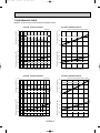
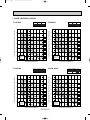
7. NOISE CRITERION CURVES
PLH18AK
NOTCH SPL(dB)
Hi
37
Lo
31
LINE
PLH24AK
80
70
NC-70
60
NC-60
50
NC-50
40
NC-40
30
NC-30
20
APPROXIMATE
THRESHOLD OF
HEARING FOR
CONTINUOUS
NOISE
NC-20
10
63
125
250
500
1000
2000
4000
80
70
NC-70
60
NC-60
50
NC-50
40
NC-40
30
NC-30
20
APPROXIMATE
THRESHOLD OF
HEARING FOR
CONTINUOUS
NOISE
PLH30AK
63
125
250
500
1000
2000
4000
8000
BAND CENTER FREQUENCIES, Hz
NOTCH SPL(dB)
Hi
43
Lo
35
LINE
PLH36,42AK
90
NOTCH SPL(dB)
Hi
45
Lo
37
LINE
90
80
70
NC-70
60
NC-60
50
NC-50
40
NC-40
30
NC-30
APPROXIMATE
THRESHOLD OF
HEARING FOR
CONTINUOUS
NOISE
NC-20
OCTAVE BAND SOUND PRESSURE LEVEL, dB re 0.002 MICRO BAR
OCTAVE BAND SOUND PRESSURE LEVEL, dB re 0.002 MICRO BAR
NC-20
10
8000
BAND CENTER FREQUENCIES, Hz
20
LINE
90
OCTAVE BAND SOUND PRESSURE LEVEL, dB re 0.002 MICRO BAR
OCTAVE BAND SOUND PRESSURE LEVEL, dB re 0.002 MICRO BAR
90
NOTCH SPL(dB)
Hi
41
Lo
33
10
80
70
NC-70
60
NC-60
50
NC-50
40
NC-40
30
NC-30
20
APPROXIMATE
THRESHOLD OF
HEARING FOR
CONTINUOUS
NOISE
NC-20
10
63
125
250
500
1000
2000
4000
8000
BAND CENTER FREQUENCIES, Hz
63
125
250
500
1000
2000
BAND CENTER FREQUENCIES, Hz
OC244-19
4000
8000
Oc244--1.qxd
7/16/2001
4:12 PM
Page 20
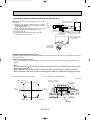
UNIT
Ambient temperature 80˚F
CEILING
Test conditions are based on JIS Z8731
5ft
MICROPHONE
OC244-20
Oc244--1.qxd
7/16/2001
5
4:12 PM
Page 21
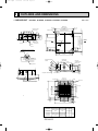
OUTLINES AND DIMENSIONS
Unit : inch
1. INDOOR UNIT PLH18AK , PLH24AK , PLH30AK , PLH36AK , PLH42AK
Ceiling hole
33-7/8~35-13/16
13/16~1-3/4
Branch duct hole
13/16~1-3/4
Terminal block
5/8
7-3/4
6-1/4
120_
33-1/16
120_
{3-15/16
(Cut out hole)
Suspension bolt M10
or W3/8
Feeding hole
(Drain pump)
11-1/4
14-3/4
2-3/8
1
Drain pipe
VP-25connection
(O.D.{1-1/4)
2-{1-1/6
Ceiling surface
Control wire entry
A
B
5-5/16
Ceiling surface
11/16~7/8
1-3/16
Power line entry
Suspension bolt lower edge
7-1/2
4-1/8
5-1/2
1-15/16~
2-3/4
6-11/16
2
High efficiency filter
& Fresh air intake casement (option)
11/16~7/8
22-11/16
Air intake hole
Air intake grille
Grille
Drain hole
M
M
Emergency operation switch (cooling)
Emergency operation switch (heating)
Auto vane
22-11/16
Air intake hole
(WIRELESS PANEL)
16-3/6
Air outlet hole
A
37-3/8
DEFROST/STAND BY lamp
M
Operation lamp
3-1/16
Receiver
M
16-3/16
Air outlet hole
37-3/8
2
6-1/4
13/16~1-3/4
3 - {1/8
Burring hole
{4-15/16
6-1/4
C
3-1/2
Deteil drawing of fresh air intake
3-7/8
7-9/16
{5-7/8
33-7/8~35-13/16
Ceiling hole
6-9/16
14 - {1/8
Burring hole
Suspension bolt pitch
23-13/16
{6-7/8
6-1/4
5-1/8
6-1/4
33-1/16
13-3/4
13/16~1-3/4
31-7/8
Suspension bolt pitch
Fresh air intake
6-1/8
70_
3-15/16
3-9/16 3-15/16 3-15/16 3-9/16
Branch duct hole
(Cut out hole)
1
Models
2
PLH24AK
Refrigerant pipe Refrigerant pipe
flared connection flared connection
3/8F
5/8F
PLH30AK
PLH36AK
PLH42AK
Refrigerant pipe Refrigerant pipe
flared connection flared connection
3/4F [42AK:7/8F]
1/2F
PLH18AK
OC244-21
Vane motor
2
3-1/16
A
B
C
9-1/2 10-3/16
3-1/8
11-1/16 11-3/4
3-5/16
Branch
duct hole
Oc244--1.qxd
7/16/2001
4:12 PM
Page 22
Unit : inch
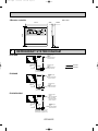
2.Remote controller
5-1/8
3/32
23/32
SWING
TIMER OFF TIMER
CLOCK AUTO AUTO
CHECK SET TEMP.
FAN
START STOP SPEED
FILTER
CHECK MODE
TEST RUN
4-3/4
AUTO
RETURN
3/4
6
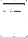
REFRIGERANT SYSTEM DIAGRAM
PLH18AK
Refrigerant pipe
(option)
{5/8"
(with heat insulator)
Flared connection
Strainer
Indoor coil
thermistor
RT2
Refrigerant pipe
(option)
{3/8"
(with heat insulator)
Flared connection
Restrictor
valve
Distributor
Capillary tube
({0.126x{0.063x14.2)
PLH24AK
Refrigerant pipe
(option)
{5/8"
(with heat insulator)
Flared connection
Strainer
Indoor coil
thermistor
RT2
Refrigerant pipe
(option)
{3/8"
(with heat insulator)
Flared connection
Restrictor
valve
Distributor
Capillary tube
({0.126x{0.071x11.8)
PLH30/36/42AK
Refrigerant pipe
(option)
{3/4"<PLH30/36AK>
{7/8"<PLH42AK>
(with heat insulator)
Flared connection
Strainer
Indoor coil
thermistor
RT2
Refrigerant pipe
(option)
{1/2"
(with heat insulator)
Flared connection
Restrictor
valve
Distributor
Capillary tube
PLH30AK ({0.157x{0.094x21.7)
PLH36AK ({0.157x{0.079x9.8)
PLH42AK ({0.157x{0.094x19.7)
OC244-22
HEATING
COOLING
Oc244--1.qxd
7/16/2001
7
4:12 PM
Page 23
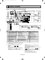
WIRING DIAGRAM
123
C
(AC208~230V) (DC13.1V) P.B
CN2S (WHT)
CNSK(RED)
TRANS
3
2
1
BZ
OFF
ON
87654321
24AK
30AK
36AK
42AK
LEGEND
SYMBOL
P.B
I.B
CN2L
CN51
FC
SW1
SW2
SW3
SW5
SW6
SW7
SW8
SW9
X1
X4
F1,F2
ZNR
LED1
LED2
RED
BLU
BLK
WHT
RED
RED
SW7
123
123
123
123
123
CN24
(YLW)
12
18,24AK
26H YLW
YLW 6 GRY
RU
5
SW1 SW2
A01
8
88H1
7
HEATER
B02
TB6
CN24
(YLW)
CN1
12
SW17 5 4 3 2 1
CN2
OFF
ON
321
TB5 87654321
2
TRANSMISSION WIRES DC12V
1
3
2
1
TRANSMISSION WIRES DC12V
TB4
YLW
YLW
MODELS
HEATER
BLK
WHT
R.B
SW18
POWER 1 3 POWER 1 2
1 3 CNDK
CND CN2D VANE
(RED)
(WHT)
(WHT) CN6V
(WHT)
F1
F2
X4
WIRELESS
9
LED1 LED2
CN90
FC
(WHT)
ZNR
X4
X1 X1
4
SW9
SW3
CENTRALLY REMOCON 3 REMOCON
BLU
CONTROL POWER
ON
CN22 2
ON
CN40 2
CN51
OFF
(BLU) 1 BLU
OFF
(WHT) 1
12345
12
OUT
BRN
SW2 SW5 SW8 SW1 SW6 SW7 HEATER DRAIN PIPE INTAKE
CN31
CN24
CN21 CN20 LOSSNAY DOOR 3 ORN
ON
ON
ON
(WHT) (WHT) (RED)
(YLW)
CN2L CN30 2
OFF
OFF
OFF
(BLU) 1 YLW
123456 12345678910 1234 123 1 2 1 2 3 1 2
123456 1234
12
CNC (ORN)
(BLU)
fig:*1
MODELS
LED2 LED1
5
D.U.M 1 3 D.HEATER 1 3
CNP
(WHT)
18AK
W.B
CNB
FAN 1 3 5
POWER SUPPLY
~(1PHASE)
AC208/230V 60Hz
L1
L2
GR
GROUND
2
1
DP
RED
WHT
BLK
I.B
F3
1 2 3 6 7 4 8 9 5 10
TB2
RED
BLU
GRN/YLW
YLW
YLW
123
RED RED
RED RED
MF
See fig:*2
YLW
YLW
H2
GRILLE
MV MV MV MV
5 5 5 5
5
RED RED
MODELS: PLH18/24/30/36/42AK WIRING DIAGRAM
30,36,42AK
26H YLW
YLW 6 GRY
5
GRY
3
2
1
8
7
88H2
YLW
8 88H1 7
TB3
OUTDOOR UNIT
ON
OFF
See fig:*1
DS
ON
OFF
ON
OFF
RT2 RT1
18,24AK
MODELS
H1
FS2 FS1 RED
30,36,42AK
1 RED 5
WHT 2 BLU 6
fig:*2
RED
4 BLU
RED
BLU
GRN/YLW
ON
OFF
H1
88H1
3
TB2
L1
L2
GR
FS2 FS1 RED
WHT
1 RED
2 BLU
88H1
5
5
3 RED
3 BLU
88H2
RED
BLU
GRN/YLW
TB2
L1
L2
GR
ON
OFF
NAME
INDOOR POWER BOARD
INDOOR CONTROLLER BOARD
CONNECTOR(LOSSNAY)
CONNECTOR(CENTRALLY CONTROL)
FAN PHASE CONTROL
SWITCH(FUNCTION SELECTOR)
SWITCH(ADDRESS SELECTOR)
SWITCH(EMERGENCY OPERATION)
SWITCH(MODEL SELECTOR)
SWITCH(TWIN/TRIPLE SELECTOR)
SWITCH(MODEL SELECTOR)
SWITCH(OPTION)
SWITCH(MODEL SELECTOR)
RELAY(DRAIN PUMP)
RELAY(FAN MOTOR)
FUSE(6A/250V)
VARISTOR
LED(DC12V POWER)
LED(DC5V POWER)
SYMBOL
NAME
C
CAPACITOR(FAN MOTOR)
MF
FAN MOTOR
MV
VANE MOTOR
DP
DRAIN-UP MACHINE
DS
DRAIN SENSOR
F3
FUSE(0.16A/250V)
H2
DEW PREVENTION HEATER
TB2~TB6 TERMINAL BLOCK
RT1
ROOM TEMP.THERMISTOR
(32-F/15k',77-F/5.4k' DETECT)
RT2
PIPE TEMP.THERMISTOR/LIQUID
(32-F/15k',77-F/5.4k' DETECT)
R.B
REMOTE CONTROLLER BOARD
CN1 CONNECTOR(PROGRAM TIMER)
CN2 CONNECTOR(REMOTE SWITCH)
SW17 SWITCH(ADDRESS SELECTOR)
SW18 SWITCH(FUNCTION SELECTOR)
SYMBOL
W.B
RU
BZ
LED1
LED2
SW1
SW2
HEATER
FS1
FS2
H1
26H
88H1,2
NAME
WIRELESS REMOTE CONTROLLER BOARD
RECEIVING UNIT
BUZZER
LED(RUN INDICATOR)
LED(HOT ADJUST)
SWITCH(HEATING ON/OFF)
SWITCH(COOLING ON/OFF)
THERMAL FUSE(162-F,16A)
THERMAL FUSE(219-F,16A)
HEATER
HEATER THERMAL SWITCH
HEATER CONTACTOR
NOTE : If the drain water lift-up mechanism is identified to be defective with the
microcomputer doctor during cooling,do not use emergency operation
(It causes drain overflow).
NOTES: 1.Since the indoor fan motor(MF)is connected with 230V power,if 208V power is
used,change the dip switch(SW8)on the indoor controller board as shown in fig:*3.
SW8
SW8
fig:*3
ON
ON
OFF
Indoor fan motor(MF)for 208V. OFF
123456
123456
2.Since the outdoor side electric wiring may change be sure to check the outdoor unit
electric wiring for servicing.
3.Indoor and outdoor connecting wires are made with polarities, make wiring matching
terminal numbers.
4.Symbols used in wiring diagram above are,
:Connector,
:Terminal block.
5.Emergency operation
If remote controller or microcomputer fails but there is no other trouble,emergency operation is
possible by setting dip switch(SW3<I.B>) on the indoor controller board.
[Check items]
(1)Make sure that no other trouble exist the outdoor unit.Trouble with the outdoor unit
prevents emergency operation.
(If any trouble exists the outdoor unit error code"P8"will be displayed on the remote
controller and the trouble position will be shown on the outdoor controller board LED.
See electric wiring diagram of the outdoor unit for details.)
(2)Make sure that there is no trouble with the indoor fan.
Emergency operation will be a continuous run with the power ON/OFF(ON/OFF with the remote
controller is not possible).
[Emergency operation procedure]
(1)Set the dip switch(SW3<I.B>)on the indoor controller board to 1 on and 2 off for cooling.
and 1 • 2 on for heating.
(2)Turn on are outdoor unit side circuit breaker,then indoor unit side circuit breaker.
(3)During emergency operation indoor fan runs at high speed but auto-vane does not work.
(4)Thermostat will not function.Cold air blows out for defrosting during heating thus do not
operate defrosting for a long time.
(5)Emergency cooling should be limited to 10 hours maximum
(the indoor unit heat exchanger may freeze).
(6)After every emergency operation,set all dip switches(SW3<I.B>) to OFF.
(7)Movement of the vanes does not work in emergency operation,therefore
you have to slowly set them manually to the appropriate position.
OC244-23
Oc244--1.qxd
8
7/16/2001
4:12 PM
Page 24
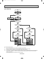
OPERATION FLOW-CHART
MAIN OPERATION
START
Power circuit
breaker
1
NO
YES
YES
Check SW
ON twice
NO
Operation SW
ON
w 1
YES
NO
“OFF” timer
YES
NO
NO
Set time
complete
“ON” timer
YES
YES
Set time
complete
NO
YES
w 2
NO
Trouble
NO
YES
STOP
Trouble STOP
PROTECTION DEVICE
SELF HOLD RELEASE
PROTECTION DEVICE
SELF HOLD
Remote controller
operation display
Operating mode
(COOL)
NO
Operating mode
(DRY)
w 3
Remote controller
trouble display
Remote controller
indicator lamp OFF
NO
Operating mode
(HEAT)
Indoor side
NO
w 4
w 6
Fan STOP
Operating mode
(FAN)
NO
Auxiliary heater OFF
YES
COOL operation
YES
DRY operation
YES
HEAT operation
YES
w 7
FAN operation
Auto COOL/HEAT
operation
Outdoor side
w 5
Compressor OFF
Fan STOP
Four-way valve OFF
w1 In addition, the centralized control and remote control can be operated.
w2 The modes which indicate the sources of trouble are listed below.
● E0-Signal transmitting/receiving error
● P1-Room temperature thermistor malfunction
● P2-Indoor coil thermistor malfunction
● P4-Drain sensor malfunction
● P5-Drain overflow
● P6-Coil frost/overheat protection
● P7-System error
● P8-Outdoor unit trouble
w3 The CHECK switch will show if an error has occurred in the past.
w4 Fan runs on low speed for 1 minute in order to remove overheat air.
w5 The 3-minute (6 minutes … heating mode) time-delay functions after compressor stops.
w6 FAN or AUTO mode is selected by the indoor dip switch setting.
w7 In FAN mode, fan speed and vane operation depend on the remote controller setting. (Compressor is OFF.)
OC244-24
Oc244--1.qxd
7/16/2001
4:12 PM
Page 25
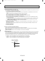
COOLING OPERATION
COOL operation
Four-way valve/OFF
NO
Initial
COOLING
w8
YES
Vane initial
setting
Vane
55 deg downward angle
70 deg downward angle
NO
YES
NO
Fan speed
LOW
YES
NO
Vane setting notch
Downward discharge
1 hour
YES
Vane horizontal
airflow
w9
Compressor
thermostat
ON
YES
NO
Allowance
cancel
NO
YES
3-minute
time delay
YES
6-minute
time delay
NO
3-minute
compressor operation
NO
Allowance
period
NO
NO
w 10
YES
6 minute
time delay
Coil frost protection
Allowance set
YES
YES
Coil frost
protection
NO
w 11
NO
Cooling area
YES
NO
10-minute
compressor operation
Indoor coil
temperature is
50˚F or higher
YES
YES
Defrosting protection
detection temperature
30˚F or lower
NO
YES
16-minute
compressor operation
6-minute
time delay
YES
Indoor pipe
temperature is
34˚F or lower
NO
Compressor ON
1 min continue
FAN speed
LOW
FAN speed
LOW 5 min
elapse
NO
NO
NO
NO
YES
YES
Allowance cancel
Coil frost
prevention
NO
3-minute
time delay
YES
Outdoor unit
trouble
YES
Coil frost
prevention
Coil frost
prevention release
Compressor OFF
1
w8 When operation stops or changes to cooling or dry mode, the auto vane turns to a horizontal angle. If operation changes
during auto vane SWING, the auto vane will continue to swing.
w9 When operating TEST RUN, the thermostat will be continuously ON.
w10After 3 minute compressor operation, if the indoor coil thermistor reads 5°F or below for 3 minutes, the compressor will
stop for 6 minutes.
w11Heating area : Indoor coil temperature is more than 9 degrees above the room temperature.
Cooling area : Indoor coil temperature is more than 9 degrees below the room temperature.
FAN area : Indoor coil temperature is within 9 degrees either way of the room temperature.
OC244-25
Oc244--1.qxd
7/16/2001
4:12 PM
Page 26
DRY OPERATION
DRY
operation
Four-way valve / OFF
NO
Initial dry
operation
w8
YES
Vane
setting notch
Vane initial setting
YES
w12
Room temperature is
64-F or lower
NO
NO
During
compressor ON
YES
3-minute
compressor
operation
NO
NO
YES
NO
YES
3-minute
time delay
w9
Compressor &
thermostat ON
YES
Compressor &
thermostat
ON
w9
NO
YES
NO
Compressor ON
time completes
10-minute
compressor
OFF
NO
YES
YES
w13
10-minute compressor
OFF timer start
Compressor ON
time set
Compressor OFF
Compressor ON
w14
Fan STOP
w14
Fan speed LOW
1
w8—9 Refer to page OC244-25.
w12
When room temperature is 64°F or below, the compressor cannot operate.
When room temperature rises over 64°F the compressor starts after a 3-minute time delay.
w13
Compressor ON time is decided by room temperature. Refer to page OC244-32.
w14
In dry operation, compressor ON makes the fan speed LOW. Also, when the compressor OFF and the pipe temperature
is 79°F or less, the fan stops, or when the compressor OFF and the pipe temperature is below 43°F the fan speed
changes to LOW mode.
It is not possible to set the fan speed with the remote controller
OC244-26
Oc244--1.qxd
7/16/2001
4:12 PM
Page 27
HEATING OPERATION
A
Heat operation
NO
initial
HEATING
w 11
Heating area
w 15
YES
3-minute
Auxiliary heater
OFF
NO
Vane initial setting
Vane setting notch
YES
NO
Indoor coil
thermistor is 140-F
or higher
NO
2
YES
YES
defrosting
YES
Defrost release
Defrost
30 min. elapse
FAN speed
Low notch
NO
1
Airflow 10% up
YES
NO
B
YES
YES
NO
10-minute
compressor
operation
YES
NO
YES
Compressor
thermostat ON
w9
NO
B
HOT adjust
5 min. elapse
YES
NO
3 min.restart
prevention
w 11
NO
YES
Auxiliary heater
ON
A
NO
YES
NO
NO
FAN STOP
w 11
Indoor piping
140-F or higher
Auxiliary heater ON
FAN SPEED
Low
FAN SPEED
Low 2 min.
elapse
YES
YES
YES
Fan area
20 min.elaspe
2
Auxiliary heater
thermostat ON
YES
NO
6 min. restart
prevention
Indoor piping
5-F or lower
YES
Heating
area
NO
FAN SPEED
setting notch
Auxiliary heater OFF
NO
Outdoor unit
trouble
Hot adjust start
FAN SPEED very low
FAN SPEED
Very low airflow
YES
w 11
Fan area
Heating area
w 10
Hot adjust
release
Overheat remote
START
Outdoor unit
trouble
NO
NO
Fan area
Cooling area
Compressor ON
NO
Indoor Coil. temp.
150-F or higher
YES
YES
Defrost operation
START
Compressor OFF
Allowance
period
Four-way valve
OFF
YES
Overload protect
NO
6-minute restart
prevention
Allowance set
1
Compressor OFF
AUTOMATIC COOLING/HEATING OPERATION
Auto COOL/HEAT
operation
w 16
NO
1
Initial mode
YES
w 17
NO
T1 >
= To
YES
HEAT mode
COOL mode
COOL mode
NO
YES
NO
NO
T1 [ (To - 4)
T1 ] (To + 4)
YES
YES
After 15min.
T1 [ (To-4)
After 15min.
T1 ] (To + 4)
YES
YES
NO
NO
COOL operation
NO
YES
YES
YES
Indoor piping
95-F or higher
NO
Indoor piping
131-F or lower
Allowance cancel
Allowance cancel
NO
NO
YES
Four-way valve ON
Compressor ON
NO
YES
Outdoor unit trouble
Hot adjust
in process
NO
HEAT operation
HEAT operation
Cool mode
set
1
1
w15 ( i ) Until Low airflow is set while in hot adjustment
( ii )While defrosting (FAN STOP)
(iii)When thermostat is OFF
In the case of( i ), (ii) and (iii) above, airflow is horizontal regardless the VANE setting.
w16 When AUTO operation is started, COOL or HEAT mode is selected automatically.
w17 T1 : Room temperature.
To : Set temperature
OC244-27
NO
FAN setting notch
Oc244--1.qxd
9
7/16/2001
4:12 PM
Page 28
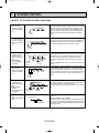
MICROPROCESSOR CONTROL
1. OUTLINE OF MICROPROCESSOR CONTROL
INPUT to remote controller
● OFF-ON switching.
● COOL/DRY-AUTO-HEAT selector switching.
● Thermostat setting.
● TIMER mode selector-switching and Timer
setting.
● HIGH-LOW fan speed switching.
● AUTO Vane selector (AIR DISCHARGE)
switching.
● TEST RUN switching.
● CHECK mode switching.
(Self diagnostic trouble shooting)
Remote controller board
● Processes and transmits
orders.
SWING
TIMER OFF TIMER
OUTPUT to indoor unit
CLOCK AUTO AUTO
FAN
START STOP SPEED
FILTER
AUTO
RETURN
CHECK MODE
TEST RUN
Non-polar, two-wire
cable maximum
length 550 yards
12VDC
● Room temperature thermistor (RT1)
● Indoor coil thermistor (RT2)
● Drain sensor
Remote controller
● LCD indicator
CHECK SET TEMP.
Indoor
unit
INPUT from indoor unit
OUTPUT to remote controller
Signal
Indoor controller board
● Receives orders from remote controller and
temperature data from indoor unit.
● Processes orders and data.
● Controls indoor and outdoor operation.
● Self diagnostic function.
w System control operation.
w Emergency operation.
w Set by dip switch on indoor controller board.
● Transmits the power to remote controller.
Auto vane’s angle setting.
Booster heater ON-OFF Control.
Drain pump : ON-OFF.
Emergency stop.
Independent Control of
Outdoor Unit
● Compressor protection
device working
● Defrosting
START-STOP
● Fan speed control.
● Crankcase heater control
ON-OFF.
● Self diagnostic function
Polar three-wire cable
Outdoor unit
12VDC
●
●
●
●
1
2
3
OC244-28
OUTPUT to outdoor unit
1 2 3
● Compressor and
outdoor fan : ONOFF.
● Operation mode
change :COOLHEAT.
Oc244--1.qxd
7/16/2001
4:12 PM
Page 29
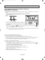
2. INDOOR UNIT CONTROL
2-1 COOL operation
<How to operate>
1 Press POWER ON/OFF button.
2 Press the MODE button to display COOL.
3 Press the SET TEMP. button to set the desired temperature.
NOTE: Set temperature changes 2°F when the SET TEMP. button
is pressed one time.
Cooling 65 to 87°F.
SWING
TIMER OFF TIMER
CLOCK AUTO AUTO
CHECK SET TEMP.
FAN
START STOP SPEED
FILTER
AUTO
RETURN
CHECK MODE
TEST RUN
<COOL operation time chart>
Operation starts by
POWER button
ON.
Room temperature
becomes equal to
set temperature.
Room temperature
rises above set
temperature.
Operation stops by
POWER button
OFF.
ON
Thermostat
OFF
ON
Indoor fan
OFF
Auto vane
OFF
LOW or HIGH
LOW or HIGH
ON
3 minutes
ON
Drain pump
OFF
Booster heater
OFF
Compressor
OFF
ON
OFF
ON
Minimum 3 minutes
w1
w1 Even if the room temperature rise above the set temperature during this period, the compressor will not start until this period has ended.
(1) Compressor control
1 3-minute time delay
To prevent overload, the compressor will not start within 3 minutes after stop.
2 The compressor runs when room temperature is higher than set temperature.
The compressor stops when room temperature is equal to or lower than the set temperature.
The compressor maintains the previous state when the room temperature minus the set temperature is 0 degrees or more,
or lower than 2 degrees.
3 The compressor stops in check mode or during protective functions.
4 Coil frost prevention
To prevent indoor coil frost, the compressor will stop when the indoor coil thermistor (RT2) reads 34°F or below after the
compressor has been continuously operated for at least 16 minutes or more. When the indoor coil temperature rises to
50°F or above, the compressor will start in a 3-minute(w2) time delay.
w2 When the indoor coil temperature is 30°F or less, the compressor starts in 6 minutes.
NOTE : By turning OFF the dip switch SW1-3 on indoor controller board, the start temperature of coil frost prevention changes
from 34°F to 36°F.
OC244-29
Oc244--1.qxd
7/16/2001
4:12 PM
Page 30
5 Coil frost protection
When indoor coil temperature becomes 5°F or below,coil frost protection will proceed as follows.
<Start condition>
After the compressor has been continuously operated for 3 minutes or more,and the indoor coil temperature has been
5°F or below for 3 minutes,the coil frost protection will start.
<Coil frost protection>
Compressor stops for 6 minutes,and then restarts.
lf the start condition is satisfied again during the first 10 minutes of compressor operation,both the indoor and outdoor
units stop,displaying a check code of“P6”on the remote controller.
<Termination conditions>
Coil frost protection is released when the start condition is not satisfied again during the allowance, or when the COOL
mode stops or changes to another mode.
(2) Indoor fan control
Indoor fan speed LOW/HIGH depends on the remote controller setting.
However, if an outdoor unit abnormality is detected, the indoor fan speed will be LOW, regardless of the remote controller
setting.
( i ) Fan speed LOW/HIGH depends on the remote controller setting regardless of the thermostat ON/OFF.
(ii) Fan speed will remain on LOW if an abnormality in outdoor unit is detected. (5 minutes)
NOTE : Fan stops immediately if the unit stops or the check mode is started.
(3) Auto vane control
Auto vane position is set to 30degrees airflow at the start-up of COOL operation.
(a) Vane position set mode & swing mode.
( i ) Every time AIR DISCHARGE button is pressed, setting will be changed .
( ii ) Airflow direction can be changed with AIR DISCHARGE button.
1 Fan speed : LOW
30°
55°
70°
SWING
55°
70°
SWING
2 Fan speed : HIGH
30°
45°
<VANE POSITION>
1 Fan speed : LOW
30
2 Fan speed : HIGH
55
70
30
45
55
70
AUTO RETURN
When 55 degrees or 70 degrees airflow is selected with the LOW fan speed in COOL operation, “AUTO RETURN” will
appear right side of the air direction display. One hour later, the airflow direction returns to 30 degrees automatically and
“AUTO RETURN” will disappear. If the airflow direction is set to 30 degrees during “AUTO RETURN” indication, the time
counting for AUTO RETURN is cancelled.
OC244-30
Oc244--2.qxd
7/16/2001
4:13 PM
Page 31
(4) Detecting abnormalities in the outdoor unit
After the compressor has been continuously operated for 3 minutes, if the difference between the indoor coil temperature
and room temperature is out of RANGE C for 1 minute, the indoor fan speed will turn to LOW. Five minutes later, if the difference is still out of RANGE C,the outdoor unit is functioning abnormally. Thus, the compressor stops and check code
“P8” appears on remote controller.
RANGE A : Indoor coil temperature is more than 9 degrees above room temperature.
RANGE B : Indoor coil temperature is within 9 degrees either way of room temperature.
RANGE C : Indoor coil temperature is more than 9 degrees below room temperature.
Indoor coil temperature
minus room temperature
(degree)
+9
RANGE A
0
RANGE B
-9
RANGE C
(5) Drain pump control
The drain pump works in COOL or DRY operation. When operation stops or changes to HEAT mode, the drain pump continues to operate for 3 more minutes. The drain pump does not work in check mode.
<Drain sensor>
When both the drain pump and unit are operating, the drain sensor detects the temperature. This temperature tells
whether the drain water level is above or under the drain sensor. If the drain water level rises above the drain sensor due
to a drain pump malfunction, the unit will stop operating in order to prevent drain from overflowing. The check code “P5” on
the remote controller will display this occurrence.
(6) Dew prevention heater
To prevent dew from accumulating on the grille, the dew prevention heater is continuously ON during COOL operation.
It is independent of the thermostat ON/OFF.
OC244-31
Oc244--2.qxd
7/16/2001
4:13 PM
Page 32
2-2 DRY operation
<How to operate>
1 Press POWER ON/OFF button.
2 Press the MODE button to display “DRY”
3 Press the SET TEMP. button to set the desired temperature.
NOTE: The set temperature changes 2°F when the SET TEMP.
button is pressed one time.
Dry 65 to 87°F
SWING
TIMER OFF TIMER
CLOCK AUTO AUTO
CHECK SET TEMP.
FAN
START STOP SPEED
FILTER
AUTO
RETURN
CHECK MODE
TEST RUN
<DRY operation time chart>
Operation starts by
POWER button
ON.
Room temperature
becomes equal to
set temperature.
Room temperature
rises above set
temperature.
Operation stops by
POWER button
OFF.
ON
Thermostat
OFF
DRY MODE
DRY MODE
ON
Indoor fan
OFF
ON
Auto vane
OFF
3 minutes
Drain pump
ON
OFF
ON
Booster heater OFF
OFF
ON
Compressor
OFF
Minimum 3 minutes w1
w1 Even if the room temperature rises above the set temperature during this period, the compressor will not start until this period has ended.
(1) Compressor control
1 3-minute time delay
To prevent overload, the compressor will not start within 3 minutes after stop.
2 The compressor runs when room temperature is higher than set temperature.
The compressor stops when room temperature is equal to or lower than the set temperature.
The compressor maintains the previous state when the room temperature minus the set temperature is 0°F or more, or
lower than 2°F.
3 The compressor stops in check mode or during protective functions.
OC244-32
Oc244--2.qxd
7/16/2001
4:13 PM
Page 33
4The compressor will not start when the room temperature is 64°F or below.
The compressor starts intermittent operation when the power is turned ON with room temperature above 64°F. The compressor ON/OFF time depends on the thermostat ON/OFF and the following room temperatures.After 3-minute compressor operation,
● If the room temperature thermistor reads above 82°F with thermostat ON, the compressor will operate for 6 more minutes and then stop for 3 minutes.
● If the room temperature thermistor reads 79°F~82°F with thermostat ON, the compressor will operate for 4 more minutes and then stop for 3 minutes.
● If the room temperature thermistor reads 75°F~79°F with thermostat ON, the compressor will operate for 2 more minutes and then stop for 3 minutes.
● If the room temperature thermistor reads below 75°F with thermostat ON, the compressor will stop for 3 minutes.
● If the thermostat is OFF regardless of room temperature, the compressor will stop for 10 minutes.
5Coil frost protection
Coil frost protection in DRY operation is the same as in COOL operation.
6Coil frost prevention
Coil frost prevention does not operate in DRY operation.
(2) Indoor fan control
The indoor fan runs on LOW speed during compressor operation. The fan speed cannot be changed with the remote controller. Also, the fan runs on LOW speed when the pipe temperature is 43°F or more, or the compressor is OFF and the
pipe temperature is below 43°F.
(a)During compressor OFF
● When the indoor coil temperature is 43°F or above, the indoor fan will stop.
● When the indoor coil temperature is below 43°F, the indoor fan will run on LOW speed.
(b)During compressor ON
● The indoor fan runs on LOW speed.
<Dry mode>
The fan notch is controlled by the indoor coil temperature every 30 seconds.
Fan control in DRY operation.
Pipe temp.
Fan
43-F or more
STOP
Below 43-F
LOW
All
LOW
Compressor OFF
Compressor ON
(3) Auto vane & drain pump controls
Same as in COOL operation
(4) Detecting abnormalities in the outdoor unit
An abnormality in the outdoor unit can not be detected in DRY operation.
OC244-33
Oc244--2.qxd
7/16/2001
4:13 PM
Page 34
2-3 HEAT operation
<How to operate>
1 Press POWER ON/OFF button.
2 Press the MODE button to display “HEAT”
3 Press the SET TEMP. button to set the desired temperature.
NOTE: The set temperature changes 2°F when the SET TEMP.
button is pressed one time.
Heating 63 to 83°F.
<Display in HEAT operation>
SWING
TIMER OFF TIMER
CLOCK AUTO AUTO
CHECK SET TEMP.
FAN
START STOP SPEED
FILTER
AUTO
RETURN
CHECK MODE
TEST RUN
[DEFROST]
The [DEFROST] symbol is only displayed during the defrost operation.
[STANDBY]
The [STANDBY] symbol is only displayed from the time the heating
operation starts until the heated air begins to blow.
<HEAT operation time chart>
Operation starts by
POWER button
ON.
Room temperature
falls below set temperature.
Room temperature
becomes equal to
set temperature.
Operation stops by
POWER button
OFF.
ON
Thermostat
OFF
Extra LOW
ON
Indoor fan
LOW
Extra LOW w1
LOW or HIGH
LOW or HIGH
OFF
ON
Auto vane
1
Horizontal
Depends on remote
controller setting
Horizontal
w1 Changeable Extra LOW or LOW
by indoor dip switch SW1- 5 and
SW1- 6 .
Depends on remote
controller setting
OFF
ON
Drain pump
OFF
OFF
ON
Booster heater
OFF
Hot adjustment
Hot adjustment
OFF during thermostat OFF
hot adjustment
defrosting
ON
Compressor
OFF
Minimum 3 minutes w2
ON
Power ON lamp
OFF
ON
STAND BY lamp
From POWER ON until
warm begins to blow
OFF
w2 Even if the room temperature falls below the set temperature during this period, the compressor will not start until this period has ended.
OC244-34
Oc244--2.qxd
7/16/2001
4:13 PM
Page 35
(1) Compressor control
13-minute time delay
To prevent overload, the compressor will not start within 3 minutes after stop.
2The compressor runs when the room temperature is lower than the set temperature.
The compressor stops when the room temperature is equal to or higher than the set temperature.
3The compressor stops in check mode or during protective functions.
4Overheat protection
<Start condition>
When the indoor coil thermistor reads 158°F or above, the overheat protection will start.
<Overheat protection>
The compressor stops for 6 minutes, and then restarts.
If the start condition is satisfied again within 10 minutes of compressor operation, both the indoor and outdoor units stop,
displaying a check code of “P6” on the remote controller.
<Termination conditions>
Overheat protection is terminated when the start condition is not satisfied again during the allowance (10-minute compressor operation), when operation mode changes to other mode, or when thermostat turns OFF.
(2) Indoor fan control
(a) Normal control
( i )The indoor fan runs on EXTRA-LOW speed during the thermostat OFF.
EXTRA-LOW speed can be changed to LOW or HIGH speed by setting the dip switch SW1-5 and SW1-6.
If the indoor coil temperature becomes more than 5 degrees below the room temperature during the thermostat
OFF, the indoor fan will stop. After, when the indoor coil temperature becomes within 5 degrees of room temperature, the indoor fan will run on EXTRA-LOW speed.
( ii )Hot adjustment
Hot adjustment is a warm-up for HEAT operation
<Start conditions>
The hot adjustment works under any of the following conditions.
● HEAT operation starts.
● Defrosting ends.
● Thermostat turns ON.
[Hot adjustment]
Initially, the indoor fan runs on EXTRA-LOW speed. When 5 minutes have passed or the indoor coil temperature
exceeds 95°F, the fan speed changes to LOW. 2 minutes later, the hot adjustment ends. Then, the fan speed
depends on the remote controller setting.
(iii)The indoor fan stops when the indoor coil temperature is within 9 degrees either way of room temperature.
(iv)To eliminate the remaining heat, the indoor fan runs for the first 1 minute after the booster heater is turned OFF.
(3) Auto vane control
Auto vane position is set to 70 degrees airflow at the start-up of HEAT operation.
(a) Vane position set mode & swing mode.
( i ) Every time AIR DISCHARGE button is pressed, setting will be changed .
( ii ) Airflow direction can be changed with AIR DISCHARGE button.
30°
45°
55°
70°
SWING
NOTE : In the following cases, the discharge direction is 30° regardless of the remote controller setting.
1 During the hot adjustment with fan speed at EXTRA-LOW
2 During defrosting with indoor fan OFF
3 During thermostat OFF
(4) Booster heater control
When the room temperature is 6 degrees below the set temperature, the booster heater will turn ON.
When the room temperature is equal to the set temperature, booster heater will turn OFF.
During the hot adjustment, the booster heater will not work.
<Overheat prevention>
When the indoor coil thermistor rises to 140°F or above, the booster heater cannot work.
When the indoor coil thermistor falls to 131°F or below, the booster heater can work.
OC244-35
Oc244--2.qxd
7/16/2001
4:13 PM
Page 36
(5) Detecting abnormalities in the outdoor unit
When the outdoor unit is determined to be abnormal by the following causes, the compressor will stop and the check code
“ P8 ” will appear on the remote controller display.
( i ) During compressor ON while hot adjustment is set.
1 If the difference between the indoor coil temperature and room temperature is in the RANGE B, the indoor fan will
stop.
2 Within 20 minutes after entering RANGE B (except for the first 10 seconds),
a) If the temperature difference enters RANGE A, the hot adjustment starts,
b) If the temperature difference is still in RANGE B, the outdoor unit is deemed abnormal.
c) If the temperature difference enters RANGE C, defrosting starts.
3 Within 20 minutes after entering RANGE C, if the temperature difference does not return to RANGE B,the outdoor
unit is deemed abnormal.
4 If the temperature difference returns to RANGE B, the next 20 minutes is an allowance period. If the difference enter
RANGE A during the allowance, defrosting ends and the hot adjustment starts. If the difference does not enter
RANGE A during the allowance, the outdoor unit is deemed abnormal.
( ii ) During compressor ON in defrosting
After 30 minutes of defrosting in hot adjustment, if the temperature difference is still in RANGE C, the outdoor unit is
determined to be abnormal.
When RANGE B does not change to RANGE A after 20 minutes have passed since RANGE C had outdoor unit is
determined to be abnormal.
( iii ) During compressor OFF
Not detecting abnormalities.
(6) Indoor coil temperature abnormality detection
An abnormality can be detected during compressor ON, except for the following.
●For the first 30 minutes after the temperature difference between the indoor coil temperature and room temperature
enters the RANGE C.
●When the temperature difference enters the RANGE C until it moves to the RANGE B.
(7) Defrosting operation
After the outdoor unit starts the defrosting operation, when the temperature difference between the indoor coil temperature
and room temperature gets out of RANGE A and into RANGE B, the indoor unit starts the defrosting mode. After the outdoor unit stops the defrosting operation, when the temperature difference returns to the RANGE A, the indoor unit stops
the defrosting mode. While the indoor unit is in the defrosting mode, the indoor fan and the booster heater stop.
w1 RANGE A : Indoor coil temperature is more than 9 degrees above room temperature.
RANGE B : Indoor coil temperature is within 9 degrees either way of room temperature.
RANGE C : Indoor coil temperature is more than 9 degrees below room temperature
Indoor coil temperature
minus room temperature
(degree)
+9
RANGE A
0
RANGE B
-9
RANGE C
OC244-36
Oc244--2.qxd
7/16/2001
4:13 PM
Page 37
2-4 AUTO operation (Automatic COOL/HEAT change over operation)
<How to operate>
1 Press POWER ON/OFF button.
2 Press the MODE button to display “AUTO”
3 Press the SET TEMP. button to set the desired temperature.
NOTE: The set temperature changes 2°F when the SET TEMP.
button is pressed one time.
Automatic 65 to 83°F.
●“AUTOMATIC” works to change by itself the operation
mode either to cooling or heating according to the room
temperature.
SWING
TIMER OFF TIMER
CHECK SET TEMP.
CLOCK AUTO AUTO
FAN
START STOP SPEED
FILTER
AUTO
RETURN
CHECK MODE
TEST RUN
(1) Initial mode
1 When AUTO operation starts after unit OFF.
● If the room temperature is higher than the set temperature, operation starts in COOL mode.
● If the room temperature is equal to or lower than the set temperature, operation starts HEAT mode.
2 When AUTO operation starts after COOL or HEAT operation, the previous mode continues.
(2 ) Mode change
1 HEAT mode changes to COOL mode when 15 minutes have passed since the room temperature became 4 degrees
above the set temperature.
2 COOL mode changes to HEAT mode when 15 minutes have passed since the room temperature became 4 degrees
below the set temperature.
To:Set temperature (65~83-F)
(degree)
When room temperature becomes 4 degrees above the set temperature,the operation mode can not be changed
for 15 minutes.
Mode change (HEAT
COOL)
To + 4
To + 2
To
To - 2
To - 4
15 minutes
COOL mode
HEAT mode
Compressor
Mode change
(COOL HEAT)
15 minutes
Start
HEAT mode
ON
OFF
Minimum 3 minutes
(3) Temperature range
AUTO operation is available under the outside air temperatures as follows.
10
0
0-F
20
30
40
50
70
80
COOLING
*
17-F
*
60
HEATING
In case of the wind baffle installed.
OC244-37
90
100
110
120 (-F)
115-F
75-F
Oc244--2.qxd
7/16/2001
4:13 PM
Page 38
2-5 Auto vane control
<How to operate>
To change the air flow direction, press AIR DISCHARGE button.
SWING
TIMER OFF TIMER
CHECK SET TEMP.
CLOCK AUTO AUTO
FAN
START STOP SPEED
FILTER
AUTO
RETURN
CHECK MODE
TEST RUN
1
30°
2
45°
3
55°
4
70°
5
SWING
1 30-
2 45- downward
3 55- downward
Available in COOL operation with fan speed on HIGH or
in HEAT operation.
Unavailable in DRY operation.
If fan speed changes from HIGH to LOW during 45°
downward airflow in COOL mode, the direction automatically changes to 30°.
4 70- downward
5 swing
Changes by pressing
the AIR DISCHARGE
button.
(1) COOL/DRY operation
At the start-up of COOL or DRY operation, the airflow direction in automatically set to 30°. After, it can be changed to
another direction with AIR DISCHARGE button on the remote controller.
<Auto return>
When 55° or 70° airflow is set with fan speed in LOW, “AUTO RETURN” appears right side of the air direction. One hour
later the direction changes to 30 degrees, automatically and “AUTO RETURN” disappears.
(2) HEAT operation
At the start-up of HEAT operation, airflow direction depends on the setting of the last operation.
After, it can be changed to another direction with AIR DISCHARGE button. The airflow direction shifts to 30° regardless of
the remote controller settings under any of the following conditions.
● Thermostat OFF
● Defrosting
● Indoor fan speed EXTRA-LOW in hot adjustment
OC244-38
Oc244--2.qxd
7/16/2001
4:13 PM
Page 39
2-6 TIMER operation
WIRED REMOTE CONTROLLER
SWING
TIMER OFF TIMER
CLOCK AUTO AUTO
CHECK SET TEMP.
FAN
START STOP SPEED
FILTER
AUTO
RETURN
CHECK MODE
TEST RUN
<Timer function>
AUTO STOP ··········The air conditioner stops after the set time lapses.
AUTO START ········The air conditioner starts after the set time lapses.
AUTO OFF ············Timer is not active.
<How to operate>
1. Press POWER ON/OFF button.
2. Press “TIMER ON/OFF” button to select AUTO STOP or AUTO
START.
3. Press “CLOCK/TIMER” button to set desired time.
Time setting is in 1 hour units for up to 24 hours.
Each time TIMER SET button is pressed, set time increases by 1
hour. When TIMER SET button is pressed and held, the set time
increases by 1 hour every 0.5 seconds.
4. To cancel the timer operation, press POWER ON/OFF button.
<Timer setting example>
AUTO
STOP
This setting will stop the operation in 8hours.
With the lapse of time, time display changes in 1hour units,
showing remaining time.
2-7 Test run
<Before test run>
● After installing, wiring, and piping the indoor and outdoor units, check for refrigerant leakage, looseness in power supply or
control wiring, and mistaken polarity.
● Use a 500-volt measure to check the resistance between the power supply terminal block and ground to make sure that it is
at least 1.0M".
Attention:
".
Do not use the air conditioner if resistance is less than 1.0M"
SWING
F
COOL
FAN
SPEED
MODE
AUTO
RETURN
TIMER ON/OFF CLOCK/TIMER FAN SPEED AIR DISCHARGE FILTER
AIR SWEEP
SET TEMP.
TIMER SET
CHECK
TEST RUN
REMOTE CONTROLLER
PAR-JH240KUS
<How to operate>
1. Turn ON main breaker.
2. Press TEST RUN button twice. “TEST RUN” is displayed on
remote controller.
3. Select “COOL” with MODE button to check that cool air is
beginning discharged.
Select “HEAT” with MODE button to check that warm air is
beginning discharged.(after a while)
4. Select LOW/HIGH with FAN SPEED button to check that the fan
speed changes properly.
5. Press AIR DISCHARGE button to check auto vane operation.
6. Check outdoor fan operation.
7. Check compressor operation referring to the indoor coil
temperature code displayed on the remote controller.
8. After checking, press the ON/OFF button.
TEST RUN button
Displayed during test run
·The test run works for 2 hours and stops automatically.
To cancel the test run, press ON / OFF button or TIMER ON / OFF button.
OC244-39
Oc244--2.qxd
7/16/2001
4:13 PM
Page 40
(1) Indoor coil temperature code
During the test run, the indoor coil temperature code from 1 to 15 is displayed on the remote controller instead of room
temperature. The code should fall with the lapse of time in normal COOL operation, and should rise in normal HEAT
operation.
Code
1
Indoor coil temperature ~34(36)°F
2
3
4
5
6
7
8
36(37)°F~50°F
~59°F
~68°F
~77°F
~86°F
~95°F
~104°F
Code
9
10
11
12
13
14
15
Indoor coil temperature
~113°F
~122°F
~131°F
~140°F
~158°F
~191°F
Thermistor abnormality
(2) Trouble during test run
● If the unit malfunctions during the test run, refer to section 10 in this manual entitled “TROUBLESHOOTING.”
● When the optional program timer is connected to the conditioner, refer to its operating instructions.
2-8 Emergency operation
When the remote controller or microprocessor malfunctions but all other parts are normal, emergency operation is started
by setting the dip switch SW3 on the indoor controller board.
<Before emergency operation>
1. Make sure the compressor and the indoor fan are operating normally.
2. Locate the defect with the self-diagnostic function. When the self-diagnostic function indicates “protective function is
working”, release the protective function before starting the emergency operation.
CAUTION: When the self-diagnostic function indicates a check code of “P5” (drain pump malfunction), do not start the
emergency operation because the drain may overflow.
<How to operate>
1. For emergency cooling, set the dip switch SW3-1 to ON and SW3-2 to OFF.
For emergency heating, set the dip switch SW3-1,2 to ON.
Emergency
cooling
1
1 ON
2
Emergency
heating
1
2
1.2 ON
Normal
operation
1
2
SW3
1.2 OFF
Indoor controller board
2. Turn ON the outdoor unit breaker and then ON the indoor unit breaker.
Emergency operation will now start.
3. During emergency operation, the indoor fan operates on high speed, the auto vanes do not operate.
4. To stop emergency operation, turn OFF the indoor unit breaker.
5. Movements of the vanes do not work in emergency operation, therefore you have to slowly set them manually to the
appropriate position.
NOTE: The remote controller POWER ON/OFF button can not start/stop emergency operations.
CAUTION: Do not use emergency cooling for more than 10 hours, as the indoor coil may freeze.
OC244-40
Oc244--2.qxd
7/16/2001
4:13 PM
Page 41
2-9 Dip switch functions
Each figure shows the initial factory setting.
(1). On remote controller board
1. SW17(Address selector)
1 2 3 4 5 6 7 8
ON
OFF
SW17-1~6) For address setting
SW17-7) When two remote controllers are used,this switch sets the controller function.
OFF:The remote controller is set as a main controller.
ON:The remote controller is set as a sub controller.
SW17-8) Switch for system back-up.
OFF:Without back-up
ON:With back-up
2. SW18(Function selector)
1 2 3 4 5 6 7 8
ON
OFF
SW18-1) Switch for timer
OFF:Single day ON:timer every day
SW18-2) Switch for filter sign
OFF:filter sign absent
ON:filter sign present
SW18-3) Switch for filter sign time setting.
OFF:100Hr ON:2500Hr
SW18-4~8) Not yet used.
(2). On indoor controller board
1. SW1 (Mode selector)
1 2 3 4 5 6 7 8 9 10
ON
OFF
SW1-1) Switch that changes between FAN mode and AUTO mode
OFF:AUTO mode for models with heat pump
ON:Fan mode for models without heat pump
SW1-2) Switch for drain pump
OFF:The drain pump works in COOL and DRY operation.
ON:The drain pump works in both COOL and DRY and HEAT operation.
SW1-3) Switch to change the temperature to start coil frost prevention
OFF:34°F
ON:36°F
SW1-4) Switch for set temperature adjustment in HEAT mode
During HEAT operation,warm air collects near the ceiling.When the indoor unit is installed near the ceiling,the
temperature read by room temperature thermistor differs from the actual living-space temperature by about 7
degrees. Therefore,the room temperature read by room temperature thermistor must be lowered by 7 degrees.
OFF:7-degree adjustment
ON:NO adjustment
SW1-5) Switch for fan speed during thermostat OFF in HEAT operation
OFF:EXTRA LOW
ON:LOW
SW1-6) Switch for fan speed during thermostat OFF in HEAT operation
OFF:EXTRA LOW or LOW(set with SW1-5)
ON:LOW or HIGH(set with remote controller)
SW1-7) Switch for detecting abnormalities in the outdoor unit abnormality detection
OFF:When an abnormality occurs,it is detected.
ON:Even if an abnormality occurs,it can not be detected.
SW1-8) Switch for auto restart function
OFF:This function does not work
ON:This function works.
SW1-9, 10) Not yet used.
OC244-41
Oc244--2.qxd
7/16/2001
4:13 PM
Page 42
2. SW2 (Address selector)
1 2 3 4 5 6
Used in setting the unit-address for group control.
For further information,refer to page OC244-55.
ON
OFF
3. SW3 (Emergency operation switch)
Normal operation
For emergency cooling
1 2
For emergency heating
1 2
ON
OFF
ON
OFF
1 2
ON
OFF
4. SW5 (Model selector)
1 2 3 4
ON
OFF
SW5-1) Not yet used
SW5-2) OFF:For models with heat pump
ON: For models with cooling only
SW5-3) OFF:Auto vane angle 30-→45-→55-→70ON: Auto vane angle 25-→40-→55-→70SW5-4) Fresh air intake OFF:Fresh air in not taken in
ON: Fresh air is taken in
5. SW6 (Address selector)
1 2 3 4
ON
OFF
This switch is not available for series PLH.
6. SW7 (Model selector)
Switch to set the output of phase-controlled indoor fan motor.
Address setting is available at any time.
The initial factory setting by is based on each capacity.
Service Ref.
SW7
PLH18AK
ON
OFF
PLH24AK
PLH30AK
ON
OFF
1 2 3
ON
OFF
ON
OFF
1 2 3
PLH36AK
1 2 3
PLH42AK
ON
OFF
1 2 3
1 2 3
7. SW8
1 2 3 4 5 6
ON
OFF
SW8-1~2) Ceiling high type switch
} See page OC244-49.
SW8-3~4) Discharge direction selector
SW8-5) Option selector
OFF:Standard
ON: When mounting the optional high
efficiency filter.
SW8-6) OFF:For 230V power supply
ON: For 208V power supply
2-10. INDOOR FAN CONTROL
Fan motor max. rotational frequency
Service Ref.
PLH18AK
PLH24,30AK
PLH36,42AK
Voltage
[V]
208/230
208/230
208/230
OC244-42
100% rotational frequency(rpm)
60Hz
600/650
710/790
760/830
Oc244--2.qxd
7/16/2001
10
4:13 PM
Page 43
TROUBLESHOOTING
1.TROUBLES IN TEST RUN
Symptom
Cause
Check points
The display “CENTRALLY
CONTROLLED” on remote
controller does not disappear.
1) Wrong address setting of remote controller/indoor controller board.
2) Timer adapter is connected to the
remote controller.
3) Signal transmission error between
indoor unit and remote controller.
1) Check the address setting of remote controller
and indoor controller.
2) Make sure the timer adapter is used correctly.
3) 1 Turn another remote controller’s DIP SW177 ON to make it sub controller.
2 Connect the sub controller to the unit, and
turn circuit breaker ON.
● If the display “centrally controlled” disappears, replace the original remote controller.
● If the display remains the same, replace the
indoor controller board.
When remote controller
POWER button is turned
ON, the check code
“E0”appears.
1) Signal transmission error between
indoor unit and remote controller
1) 1 Connect a sub remote controller.
2 Turn circuit breaker ON.
If the display “centrally controlled” remains,
replace the indoor controller board.
3 If the display disappears, turn the remote
controller POWER button ON and check as
follows.
Remote controller
Sub remote controller
1 Operating Display
E0 Display
2 Operating Display
Operating Display
3 No Display
E0 Display
4 No Display
Operating Display
Malfunction
Malfunction of
indoor Unit
Malfunction of
Remote controller
Malfunction of
indoor Unit and
Remote Controller
Malfunction of
Remote controller
When remote controller
POWER button is turned
ON, operating display
appears, but disappears
soon.
1) Short circuit of indoor/outdoor connecting wire
2) Short circuit of transmission wire.
3) Wrong operation of remote controller
due to noise wave emitted by other
appliances.
1), 2) Check the wire
3) Turn the circuit breaker OFF, and then turn
ON.
If the remote controller remains abnormal,
despite the above measures, replace the indoor
controller board.
Despite turning POWER
button ON, the remote
controller display does not
appear.
1) Damaged remote controller.
2) Short circuit of transmission wire.
3) Bad contact of indoor CN40.
4) CN40 is attached to a sub unit.
5) Damaged power board.
6) Bad contact of CN2D.
7) Blown fuse.
8) Circuit breaker OFF.
1) Measure the voltage between terminals of
remote controller. If no voltage, remove the
terminals and measure the voltage between
wires. If the voltage is between 6VDC and
12V, replace the remote controller.
2) ~ 8) Check each point.
If it is not defective, replace the indoor
controller board.
OC244-43
Oc244--2.qxd
7/16/2001
4:13 PM
Page 44
2. SELF DIAGNOSTIC FUNCTION WITH REMOTE CONTROLLER
(WIRED REMOTE CONTROLLER)
2-1 When malfunction occurs during operation
When a malfunction occurs, the indoor and outdoor units stop and the malfunction is displayed on the LCD of the remote
controller.
(1) ON the set temperature display part, “CHECK” appears, and the unit CHECK mode
address and the check code are displayed alternately at one-second
intervals. (Check mode)
Example
Check
code
Unit
address
MODE
TIMER ON/OFF CLOCK/TIMER FAN SPEED AIR DISCHARGE FILTER
AIR SWEEP CHECK
(2) When one remote controller controls several units in the group control, the LCD shows the unit address and check code of the first malfunctioning unit.
(3) To cancel the check mode, press the ON/OFF button. In remote
ON/OFF control, press the remote ON/OFF switch. In centralize
control, turn OFF the ON/OFF button of centralize controller.
SET TEMP.
TIMER SET
TEST RUN
REMOTE CONTROLLER
PAR-JH24KUS
Check button
NOTE: The latest check code is memorize, even if the check mode is cancelled by the way mentioned above. It takes 60
seconds maximum to display the memorize check code.
2-2 How to use the self diagnostic function for service
A. For normal control with one unit and one remote controller
(1) Pressing the CHECK button on the remote controller twice starts the self diagnostic function.
(2) During the self diagnostic function, “CHECK MODE” appears at two positions on the remote controller display. Then, at
least 10 seconds later, the unit address and the check code is alternately displayed at one-second intervals.
(3) Check and repair the unit according to the check code. (Refer to next page.)
B. For group control using one remote controller
(1) Pressing the CHECK button on the remote controller twice starts the self diagnostic function.
(2) Press the
SET TEMP. button or
SET TEMP. button on the remote controller to advance or go back to the
unit address. Each time
SET TEMP. button is pressed, the unit address advances by one. Each time
SET
TEMP. button is pressed, the unit address goes back by one.
The check code and the unit address, appear alternately.
(3) The check code “U8” means no malfunction has occurred since installation.
The check code “E0” means the following conditions:
● The unit address displayed on the remote controller does not apply to any unit.
● power is not supplied to the unit.
● Signal transmitting/receiving circuit is abnormal.
(4) Check and repair the unit according to the check code. (Refer to next page.)
OC244-44
Oc244--2.qxd
7/16/2001
4:13 PM
Page 45
Check
Check points
Diagnosis of malfunction
Cause
code
E0
Signal transmitting/receiving During individual unit control
1) Check the transmission wire.
error
1) Bad contact of transmission
2) Check with another remote controller. If “E0” is
(Indoor controller does not
wire
still indicated, replace the indoor controller
respond to remote controller 2) Signal transmitting/receiving cirboard.
signal.)
cuit is abnormal.
If other check code appears. replace the original remote controller.
P1
Abnormality of room temper- 1) Bad contact of thermistor
ature thermistor (RT1)
2) Damaged thermistor
P2
Abnormality of indoor coil
thermistor (RT2)
P3
Signal transmission error
(Remote controller does not
respond to indoor controller
signal.)
1) Check the transmission wire.
1) Bad contact of transmission
2) Check with another remote controller.
wire
If “P3” is still indicated, replace the indoor
2) Signal transmitting/receiving cirboard.
cuit is abnormal.
If other check code appears, replace the origi3) Wrong operation due to noise
nal remote controller.
wave emitted by other appli3) Short-circuit between 1 and 2 of CN40 and
ances
attach CN40 to the following units.
● Second unit in twin control
● Second and third units in triple control
● Sub units in group control
P4
Abnormality of drain sensor
1) Bad contact of transmission
wire
2) Damaged thermistor
1) Check the connector.
2) Measure the resistance of the thermistor 1 - 3.
32°F ··6k"
59°F····3.2k" 86°F····1.8k"
41°F ··4.8k" 68°F····2.6k" 95°F····1.5k"
50°F ··3.9k" 77°F····2.2k" 104°F··1.3k"
If the resistance is normal, replace the indoor
controller board.
P5
Malfunction of drain pump
1) Malfunction of drain pump
2) Damaged drain sensor
1) Check the drain pump.
2) ● Check the drain sensor.
(Check the drop of water is on.)
If the resistance is normal, replace the indoor
controller board.
P6
Freezing protection/
overheating protection
is working.
1)
2)
3)
4)
1)
2)
3)
4)
P7
System error
1) Wrong address-setting
1)
2) Signal transmitting/receiving cir- 2)
cuit of remote controller is
abnormal.
3) Wrong SW6-setting
3)
Check the address-setting.
Check with another remote controller. If check
code other than “P7” appears, replace the original remote controller.
Check SW6 setting.
P8
Abnormality in outdoor unit
1) Wrong wiring of indoor/outdoor
connecting wire
2) Reversed phase
3) Protection device is working
4) Damaged outdoor coil thermistor
Check the indoor/outdoor connecting wire.
Change the connection of electric wiring.
Check the protection device.
Measure the resistance of the outdoor coil thermistor. If the resistance is normal, replace the
outdoor controller board.
Short cycle of air cycle
Dirty air filter
Damaged fan
Abnormal refrigerant
OC244-45
1) Check the thermistor.
2) Measure the resistance of the thermistor.
Normal resistance should be as follows.
32°F····15k"
86°F ····4.3k"
50°F····9.6k" 104°F ····3.0k"
68°F····6.3k"
If the resistance is normal, replace the indoor
controller board.
1)
2)
3)
4)
Clear obstructions from the air cycle.
Clean the air filter
Check the fan.
Check the refrigerant temperature.
Oc244--2.qxd
7/16/2001
4:14 PM
Page 46
3. OTHER TROUBLES AND CAUSES
Vanes do not work.
Unit stops after 5 to
20 seconds operation
Air discharge display
is OFF and AIR DISCHARGE button does
not operate.
In this case, remote
controller is normal.
Power ON/OFF button
is not available.
Vane motor does not work.
Connector is poorly connected.
Vane motor is poorly assembled.
Indoor controller board is damaged.
Vane motor is damaged.
Vane motor relay is damaged.
Protection function is working.
Refer to check code on remote controller display.
See page OC244-45.
Indoor controller board
deems the auto vanes
are not attached to the
unit.
Horizontal angle can
not be detected.
Beep sound is heard,
but display is turned
OFF.
Beep sound is not heard,
and display remains OFF.
Indoor controller is
damaged.
Dip switch setting is
wrong.
Indoor controller is
damaged.
Vane motor is damaged.
Auto vane is wired after
power is turned to ON.
Vane motor is damaged.
Indoor/outdoor connecting wire is connected
incorrectly.
Indoor/outdoor connecting wire shorts.
Compressor protector
is damaged.
Outdoor controller
board is defective.
Remote controller is
damaged.
Transmission wire is
poorly connected
“CENTRALLY CONTROLLED” is displayed.
OC244-46
Transmission wire is
damaged.
Connector is poorly
connected.
Indoor terminal block is
poorly connected.
Remote controller terminal block is poorly
connected.
Oc244--2.qxd
7/16/2001
4:14 PM
Page 47
4. How to check the parts PLH18AK/PLH24AK/PLH30AK/PLH36AK/PLH42AK
Parts name
Check points
Room temperature
thermistor
(RT1)
Liquid pipe
thermistor
(RT2)
Vane motor
Disconnect the connector then measure the resistance using a tester.
(Surrounding temperature 50-F~86-F)
Normal
Abnormal
4.3k"~9.6k"
Open or short
(Refer to the thermistor)
Measure the resistance between the terminals using a tester.
(Surrounding temperature 68-F~86-F)
White 4
Connector
M
Normal
Abnormal
300"
Open or short
Red — Yellow
Orange 2
Red — Blue
Red 1
5
3
Blue
Yellow
Fan motor
Red — Orange
Red — White
Measure the resistance between the terminals using a tester.
Relay connector
1
Red
2 White
3 Black
1
2
3
Normal
Motor terminal
or
Relay connector
18AK
24,30AK
36,42AK
Red-Black
87.2"
32.6"
28.7"
White-Black
104.1"
40.7"
41.6"
Abnormal
PLH
Protector
Drain pump
Measure the resistance between the terminals using a tester.
(Surrounding temperature 68-F~86-F)
Yellow
1
Normal
Abnormal
2
319"
Open or short
Yellow
Drain sensor
Measure the resistance between the terminals using a tester.
(Surrounding temperature 50-F~86-F)
1
2
3
Normal
Abnormal
0.6k"~6.0k"
Open or short
OC244-47
(Refer to the thermistor)
Open or short
Oc244--2.qxd
7/16/2001
4:14 PM
Page 48
<Thermistor Characteristic graph>
Thermistor for
lower temperature
< Thermistor for lower temperature >
Room temperature thermistor(RT1)
Liquid pipe thermistor(RT2)
50
Resistance (K")
40
Thermistor R0=15k' ± 3%
Fixed number of B=3480k' ± 2%
30
20
Rt=15exp { 3480(
32°F
50°F
68°F
77°F
86°F
104°F
1
273+{(t-32)/1.8}
1 )}
273
10
15k'
9.6k'
6.3k'
5.2k'
4.3k'
3.0k'
0
Thermistor for
drain sensor
10
-4
14
32 50 68 86
Temperature (-F)
104 122
< Thermistor for drain sensor >
9
Thermistor R0=6.0k' ±5%
Fixed number of B=3390k' ±2%
8
Rt=6exp { 3390(
32°F
50°F
68°F
77°F
86°F
104°F
1
273+{(t-32)/1.8}
Resistance (K")
7
1 )}
273
6.0k'
3.9k'
2.6k'
2.2k'
1.8k'
1.3k'
6
5
4
3
2
1
0
-4
OC244-48
32
68
104 140
Temperature (-F)
176
Oc244--2.qxd
7/16/2001
4:14 PM
Page 49
4-WAY AIR FLOW SYSTEM
11
1. Placement of the air outlets
• For this grille, the blowout direction comes in 11 patterns.
Also, by setting the dip switches (SW8-3, SW8-4) on the indoor board to the appropriate settings, you can adjust the air flow
and speed. Select the settings from Table according to the location in which you want to install the unit.
1) Decide on the pattern of the airflow direction.
Blowout direction
pattern
<Table 1>
4-direction
Pattern 1
Factory setting
3-direction
Pattern 4
One air outlet
fully closed
2-direction
Pattern 6
Note1.
For 3 and 2-directional,
please use the air outlet
shutter plate (option).
Two air outlet
fully closed
2) According to the number of air outlets and height of the ceiling to install the unit, be sure to set the up switches
(SW8-3, SW8-4) on the indoor board to the appropriate setting.
• Correspondence of ceiling heights to numbers of air outlets.
Ceiling height & discharge direction
(Unit : feet)
High ceiling 1 High ceiling 2
Standard
SW8-1 ON
SW8-1,2 SW8-1 OFF SW8-1 ON
SW8-2 OFF SW8-2 OFF SW8-2 ON
SW8-3,4
SW8-3 OFF
4 direction SW8-4 OFF
8.9
9.8
11.5
3 direction SW8-3 ON
9.8
10.8
11.5
SW8-4 OFF
2 direction SW8-3 ON
10.8
11.5
—
SW8-4 ON
PLH18AK
I.B
PLH24, 30, 36, 42AK
High ceiling 1 High ceiling 2
Standard
SW8-1 ON
SW8-1 ON
SW8-1
OFF
SW8-1,2
SW8-2 OFF SW8-2 OFF SW8-2 ON
SW8-3,4
SW8-3 OFF
4 direction SW8-4 OFF
10.5
11.8
13.8
3 direction SW8-3 ON
11.8
13.1
13.8
SW8-4 OFF
2 direction SW8-3 ON
13.1
13.8
—
SW8-4 ON
SW8
2. Fresh air intake (Installation of site)
• At the time of installation, use the duct holes (cut out) located at the positions shown in following diagram, as and when
required.
Note :
Be sure to add5-5/16inch to the dimensions in the diagram that are marked with a “w” if installing a multi function casement
(Option)
Fresh air intake hole
Fresh air intake hole diagram
3 - {1/8
Burring hole
{4-15/16
Burring hole pitch
Refrigerant pipe
Drain pipe
OC244-49
120_
w6-1/4
120_
{3-15/16
(Cut out hole)
Ceiling surface
(Unit : inch)
Oc244--2.qxd
7/16/2001
4:14 PM
Page 50
3. Fresh air intake amount & static pressure characteristics
l PLH18AK
Multifunction casement + Standard filter
Static pressure [in. W.G.
Multifunction casement + High efficiency filter
O10-2]
Static pressure [in. W.G. O10-2]
20
50
100
150
50
200
-20
150
Air flow [CFM]
2 intakes
-40
-60
-60
1 intake
-80
1 intake
-80
Taking air into the unit
How to read curves
Static pressure [in. W.G. O10-2]
1
20
Curve in the
left graphs.
100
150
A
200
B
50
Q…Planned amount of fresh air intake
<CFM>
A…Static pressure loss of fresh air
intake duct system with air flow
<in.W.G.O10-2>
amount Q
B…Forced static pressure at air conditioner inlet with air flow amount Q
<in.W.G.O10-2>
C…Static pressure of booster fan with
air flow amount Q
<in.W.G.O10-2>
D…Static pressure loss increase
amount of fresh air intake duct system for air flow amount Q
<in.W.G.O10-2>
E…Static pressure of indoor unit with air
flow amount Q
<in.W.G.O10-2>
Qa…Estimated amount of fresh air
intake with out D
<CFM>
Duct characteristics
at site
0
Air flow [CFM]
Q
-20
C
A
2
E
-40
-60
Q
-80
A
D
3
Q
Qa
2 PLH24/30/36/42AK
Multifunction casement + Standard filter
Multifunction casement + High efficiency filter
Static pressure [in. W.G. O10-2]
tatic pressure [in. W.G. O10-2]
20
20
50
0
50
100
150
200
250
300
Air flow
[CFM]
-20
100
150
200
250
0
-60
-60
-80
-80
Taking air into the unit
Static pressure [in. W.G. O10-2]
20
50
100
150
200
250
2 intakes
-40
1 intake
300
Air flow [CFM]
-20
-40
-60
-80
OC244-50
300
Air flow
[CFM]
-20
2 intakes
-40
0
200
-20
2 intakes
-40
0
100
0
Air flow [CFM]
C
0
20
1 intake
Oc244--2.qxd
7/16/2001
4:14 PM
Page 51
4. Interlocking operation method with duct fan (Booster fan)
●Whenever the indoor unit is operating, the duct fun also
operates.
(1)Connect the optional multiple remote controller
adapter(PAC-SA88HA-E)to the connector CN51 on the
indoor controller board.
(2)Drive the relay after connecting the 12V DC relay
between the Yellow and Orange connector lines.
Use a relay under 1W.
MB: Electromagnetic switch power relay for duct fan.
X: Auxiliary relay (12V DC LY-1F)
~
Be sure to secure insulation
material by tape and such
CN51
on
indoor unit
board
5
Green
Yellow
MB
Orange
1
Connector (5P)
Red
Brown
Package side
Installation at site
Multiplr remote
controller adapter
PAC-SA88HA-E
Be sure to secure insulation
material by tape and such
Indoor controller board
Distance between indoor
controller board and relay
must be within 10m.
CN51
Multiple remote
controller adapter
PAC-SA88HA-E
CN51
5. BRANCH DUCT(Installation at site)
Discharge by branch duct becomes possible by installing a branch duce at site. Knockout holes on the wall panel of the indoor
unit must be removed.
Branch Duct Installation Procedure
At the time of installation, use the duct holes (cut out) located at the positions shown in following diagram, as and when
required.
Note :
The figure marked with w in the drawing represent the dimensions of the main unit excluding those of the optional
multi function casement.
When installing the optional multi function casement, add 5-5/16 inch to the dimensions marked on the figure.
When installing the branch ducts, be sure to insulate adequately. Otherwise condensation and dripping may occur.
Figure 1. Branch duct mounting position
Figure 2. Branch duct connection details
Unit : (inch)
Branch duct hole
(Cut out hole)
Branch
duct hole
w6-1/8
Branch
duct hole
{6-7/8
Burring hole pitch
Refrigerant pipe
Drain pipe
OC244-51
13-3/4
14 - {1/8
Burring hole
{5-7/8
Cut out hole
w6-9/16
70_
3-15/16
3-9/16 3-15/16 3-15/16 3-9/16
5-1/8
Branch duct hole diagram
(view from either side)
Fresh air intake hole
Oc244--2.qxd
7/16/2001
4:14 PM
Page 52
6. Air flow & Static pressure characteristics of Branch Duct (with SWA at “Standard”)
4 direction airflow (Horizontal vane)
Rectangular duct
PLH18AK
Rounded duct
PLH18AK
12
12
Static
8
pressure
[in. W.G. O10-2]
Static
8
pressure
[in. W.G. O10-2]
Hi
4
4
Hi
Lo
0
50
Lo
100
150
0
200
50
100
Air flow [CFM]
150
200
Air flow [CFM]
PLH24AK
PLH24AK
20
20
16
Static
pressure
12
-2
[in. W.G. O10 ]
16
Static
pressure
12
[in. W.G. O10-2]
8
0
8
Hi
0
50
Hi
4
Lo
4
100
150
200
250
300
350
Lo
50
100
150
PLH30/36/42AK
20
16
Static
pressure
12
[in. W.G. O10-2]
16
Static
pressure
12
[in. W.G. O10-2]
Hi
8
4
4
Lo
50
100
150
200
250
300
3 direction airflow (Horizontal vane)
Rectangular duct
PLH18AK
0
350
350
Lo
50
100
150
24
20
Static
12
pressure
[in. W.G. O10-2]
16
Static
12
pressure
[in. W.G. O10-2]
Hi
250
300
Rounded duct
PLH18AK
20
16
200
Hi
8
8
Lo
4
100
150
Lo
4
0
50
200
250
300
50
100
150
200
250
300
Air flow [CFM]
Air flow [CFM]
PLH24AK
PLH24AK
Hi
Lo
350
Air flow [CFM]
24
40
36
32
28
Static
24
pressure
20
[in. W.G. O10-2] 16
12
8
4
0
300
Hi
8
Air flow [CFM]
0
250
PLH30/36/42AK
20
0
200
Air flow [CFM]
Air flow [CFM]
40
36
32
28
Static
24
pressure
20
[in. W.G. O10-2] 16
12
8
4
0
50 100 150 200 250 300 350 400 450
Hi
Lo
50 100 150 200 250 300 350 400 450
Air flow [CFM]
Air flow [CFM]
OC244-52
Oc244--2.qxd
7/16/2001
4:14 PM
Page 53
3 direction airflow (Horizontal vane)
Rectangular duct
PLH30/36/42AK
40
36
32
28
Static
24
pressure
20
-2
[in. W.G. O10 ] 16
12
8
4
0
Rounded duct
PLH30/36/42AK
40
36
32
28
Static
24
pressure
20
-2
[in. W.G. O10 ] 16
12
8
4
0
Hi
Lo
50 100 150 200 250 300 350 400 450
Hi
Lo
50 100 150 200 250 300 350 400 450
Air flow [CFM]
Air flow [CFM]
2 direction airflow (Horizontal vane)
Rectangular duct
PLH18AK
Rounded duct
PLH18AK
100
90
100
80
80
90
70
60
50
70
Static
pressure
[in. W.G. O10-2] 40
30
20
10
0
Hi
60
Static
50
pressure
[in. W.G. O10-2] 40
30
Lo
Lo
20
10
0
50 100 150 200 250 300 350
Air flow [CFM]
PLH24AK
120
110
100
90
80
Static
70
pressure
60
-2
[in. W.G. O10 ] 50
40
30
20
10
0
Hi
50 100 150 200 250
Air flow [CFM]
PLH24AK
Hi
Lo
50 100 150 200 250 300 350 400 450 500 550
120
110
100
90
80
Static
70
pressure
60
-2
[in. W.G. O10 ] 50
40
30
20
10
0
Hi
Lo
50 100 150 200 250 300 350 400 450 500 550
Air flow [CFM]
PLH30/36/42AK
120
110
100
90
80
Static
70
pressure
60
-2
[in. W.G. O10 ] 50
40
30
20
10
0
Air flow [CFM]
PLH30/36/42AK
Hi
Lo
50 100 150 200 250 300 350 400 450 500 550
120
110
100
90
80
Static
70
pressure
60
-2
[in. W.G. O10 ] 50
40
30
20
10
0
Hi
Lo
50 100 150 200 250 300 350 400 450 500 550
Air flow [CFM]
Air flow [CFM]
OC244-53
Oc244--2.qxd
12
7/16/2001
4:14 PM
Page 54
SYSTEM CONTROL
1. VARIETY OF SYSTEM CONTROL FUNCTIONS
1
2
Group control
with a single
remote controller
(See page OC24455.)
Unit
Unit
Many units, installed at different locations, can be started
and controlled with a single remote controller. The remote
controller can be mounted in a different location using a
non-polar two-wire cable, which can be extended up to
500m. A maximum of 50 units can be controlled with a
single remote controller. All units operate in the same
mode.
Unit
Remote
controller
Control using two
remote controllers
(See page OC24456.)
Unit
Unit
Two remote controllers can be used to control either one
unit or a group of units. Units can then be controlled from
a distance or at close range. Units operate according to
the latest command from either remote controller.
Unit
Remote
controller
3
Both remote
ON/OFF and individual controls
(See page OC24456.)
w Timer adapter
(PAC-SA89TA-E)
is needed.
4
Optional
adapter
Relay box
Unit
Remote
ON/OFF
switch
Individual control
by grouping
remote controllers
(See page OC24457.)
Remote
controller
Unit
Unit
By grouping the remote controllers in one place, several
units installed at different locations can be controlled individually, and operation conditions of all units are visible
without a special control board. The control method is the
same as that of the single unit with a single remote controller.
Unit
Remote
controller
5
Multiple remote
control display
(See page OC24458.)
w Multiple display
adapter
(PAC-SA88HA-E)
is needed.
6
Auto restart function
(See page OC24458.)
Unit
Remote control
display board
Unit
All units can be turned on or off simultaneously using a
remote ON-OFF switch. Also, each unit can be controlled
individually by each remote controller. Dunning remote
ON-OFF control, a message of “CENTRALLY CONTROLLED” is displayed on the LCD of the remote controller.
This is available for both one unit control and several units
control.
Unit
Several units can be controlled with a remote control display board. Operation conditions of all the units are visible with the remote control display board.
Individual control by each remote controller is also possible.
Remote
controller
Circuit breaker
Remote
controller
A unit can be started or stopped with the circuit breaker
on or off.
Remote controller is also available.
With this function, when the power is restored after power
failure, the unit will restart automatically. (However, when
the remote controller POWER ON/OFF button is OFF, the
unit will not start.)
OC244-54
Oc244--2.qxd
7/16/2001
4:14 PM
Page 55
2. GROUP CONTROL WITH A SINGLE REMOTE CONTROLLER
A maximum of 50 units can be started in order according to the dip switch settings
Figure 1
To remote
controller
To next
unit
To next unit
L1 L2 GR 1 2 3
Master unit
electrical box
L1 L2 GR 1 2 3
2-1 How to wire
(1) Connect the remote controller to the double terminal block
on the indoor controller board of the master unit (No.0 unit).
(See Figure 1.)
(2) Connect the double terminal block of the master unit to the
double terminal block of No.1 unit.
(3) Connect the double terminal block of No.1 unit to the double terminal block of No.2 unit.
(4) Continue the process until all the units are connected with
two-wire cables. (See Figure 2.)
(5) Remove the connector CN40 from the indoor controller
board of each unit except the master unit. (See Figure 3.)
(6) Set the unit-address of each unit with SW2 on the indoor
controller board following the instructions below.
2-2 How to set unit-address
The unit-address also serves as a successive-start timer which
starts each unit at intervals of 1 second. If two or more units
have the same unit-address in a group control, operation stops
due to system error. Be sure to set SW2 correctly following the
instructions below.
(1) Each lever of SW2 shows the number as follows.
SW2-1 : 1
SW2-4 : 8
SW2-2 : 2
SW2-5 : 16
SW2-3 : 4
SW2-6 : 32
(2) Total number of levers turned to ON shows the address of
the unit.
For example, to set No.3 unit, turn ON SW2-1 and SW2-2.
(3) In this way, set from the master unit to the last unit.
Do not forget to set the master (No. 0) unit.
Next unit
electrical box
The last unit
dose not have
this wire.
Figure 2
Master
unit
No.1 unit
No.2 unit
Last unit
2-wire cable
Figure 3
Indoor controller board
▼
Should be removed
from all units other
than unitNo.0:
(Master Unit).
CN40
CN40
SW2
SW2
ON
1
2
3
4
5
6
Setting examples
Master (No. 0) unit
No. 1 unit
No. 2 unit
No. 4 unit
No. 8 unit
No. 16 unit
No. 32 unit
ALL OFF
1 ON
2 ON
3 ON
4 ON
5 ON
6 ON
SW2
1
Unit address & start
delay in seconds.
2
3
4
5
6
1
0
2
3
4
5
6
1
1
2
3
4
5
6
1
2
2
3
4
5
6
1
4
2
3
4
5
6
1
8
2
3
16
4
5
6
1
2
3
4
32
2-3 Unit control
The remote controller can control all units ON/OFF, temperature, air flow, and swing louver. However, the thermostat in
each unit turns ON or OFF individually to adjust to the room temperature.
OC244-55
5
6
Oc244--2.qxd
7/16/2001
4:14 PM
Page 56
3. CONTROL USING TWO REMOTE CONTROLLERS
Two remote controllers can be used to control either one unit or a group of units. Units operate according to the latest command from either of the two remote controllers.
Before operation, be sure to set one remote controller as the “main controller” and the other as the “sub controller”, using dip
switch SW17-7 of the remote controller.
Figure 4
Individual
Multiple operation
operation
Remote
controller
Remote
controller
Remote
controller
Remote
controller
3-1 How to set SW17-7 (See Figure 5.)
(1) For the main remote controller, turn SW17-7 OFF.
(2) For the sub remote controller, turn SW17-7 ON.
3-2 Remote controller LCD indication
(1) The same indications always appear on both the
main and sub remote controllers, except during the
timer operations.
(2) Timer operations can be set with either of the two
remote controllers. However, LCD indication appears
only on the remote controller used for timer-settings.
(3)If both remote controllers are set for timer operation
with different time-settings, the timer operation with
the shorter remaining-time is effective.
(4) Self-diagnostic function is available with either of the
two remote controllers. If one of the remote controllers is used for the self-diagnostic function, the
other remote controller displays the check mode.
If the self-diagnostic function is reset by either of the
two remote controllers, both remote controllers are
reset.
Figure 5
Remote controller
SW17
Main remote controller
Sub remote controller
F
OF
8
7
6
5
4
3
2
F
OF
1
8
7
6
5
4
3
2
1
Turn SW17-7 ON.
4. REMOTE ON-OFF AND INDIVIDUAL REMOTE CONTROLS
This method is available to control one unit or any number of units.
The following operations are available by connecting a relay, a timer adapter (PAC-SA89TA-E), and a remote ON/OFF switch
to the system. Timer adapter is an optional part. Other parts are available on the market.
(A) To start all units in order by remote ON-OFF switch
(B) To stop all units simultaneously by remote ON-OFF switch
(C) To switch between the remote ON-OFF control and the individual remote control
4-1 System
Figure 6 shows the case of three units. The same is the case with any number of units.
Figure 6
Timer adapter
PAC-SA89TA-E
power supply of
control circuit
Remote
ON/OFF
switch
Relay box
2-wire
remote
Timer adapter cables
controller
cable
Remote
controller
OC244-56
Oc244--2.qxd
7/16/2001
4:14 PM
Page 57
NOTE1 : Install the relay box where you can be serviced it easily.
NOTE2 : For control circuit wiring, use a wire of No. 14 AWG or a control cable according to the power supply of control
circuit.
NOTE3 : When the power supply of the control circuit is 208/230V AC,
● Do not connect the control circuit wire to the remote controller cable directly.
● Do not place the control circuit wire and the remote controller cable into the same conduit tube.
4-2 Basic wiring
Caution : Before starting all units simultaneously by the remote ON-OFF switch, be sure to connect a sequence-start timer
into the remote ON-OFF circuit. Otherwise, a rush of starting current may damage the power supply.
Remote
ON/OFF
switch
Power
supply
No.1 unit
relay box
No.2 unit
relay box
SW1
Next unit
SW2
Glow switch or pilot lamp can be
combined to easily identify the
on-off mode of SW1 and SW2.
To
No.1
unit
T
T
X2
X2
T
To
No.2
unit
X2
T
X2
Remote controller
Timer adapter cables
4-3 Switch function of remote ON-OFF switch
SW1
(Switches between
remote ON and OFF.)
ON
(Start)
OFF
(Stop)
SW2
(Switches between remote ON-OFF and individual control)
ON
OFF
(Remote ON-OFF control)
(Individual control)
All units start together.
w1
Each unit can be controlled by each
Individual control is not available.
remote controller.
All units stop together.
w2
Remote ON-OFF switch is not available.
Individual control is not available.
w1After all units start together, if SW2 is turned OFF, each unit can be individually stopped by each remote controller.
w2After all units stop together, if SW2 is turned OFF, each unit can be individually started by each remote controller.
5. INDIVIDUAL CONTROL BY GROUPING THE
REMOTE CONTROLLERS
● Grouping the remote controllers allows individual control and centralize monitoring of units installed in different places without a special control board.
● Remote control cables are extendible up to 550 yards When the
cable length exceeds 33ft, use the double-insulated two-care cable
such as Belden 9407. Also, the cable thickness must be No. 22
AWG or above.
● When gathering the power ON/OFF switches of air conditioners
near the remote controllers, you should also install the power
ON/OFF switch near each unit to prevent electric trouble during
servicing.
OC244-57
Remote
controller cable (2-core)
Remote controller
Oc244--2.qxd
7/16/2001
4:14 PM
Page 58
6. MULTIPLE REMOTE CONTROL DISPLAY
Indoor controller board
You can control several units with a multiple remote control display, by
wiring an optional multiple display adapter (PAC-SA88HA-E) with relays
and lamps on the market.
How to wire
(1) Connect the multiple display adapter to the connector CN51 on the
indoor controller board.
(2) Wire three of the five wires from the multiple display adapter as shown
in the figure below.
<Wiring >
X2
YELLOW
X1
ORANGE
RED
Electrical insulation is needed.
BROWN
1
connector(5P)
GL
X2
GREEN
5
CN51
CN51
Optional multiple display
adapter
X1
RL
Power
supply
Wiring at the actual place
CN51
The maximum distance between
indoor board and relay is 33ft.
[Notes on Signs]
X1:Relay (for operation lamp)
X2:Relay (for check lamp)
RL:Operation Lamp
GL:Check Lamp
[Field supplied parts]
Relays:12V DC with rated coil power
consumption below 0.9W.
Lamps:Matching to power supply voltage.
<System>
3wires
3wires
3wires
Power
supply
No.1 unit
2wires
No.2 unit
Remote
controller
cable
Multiple remote control
ON-OFF display
(Field supply)
Remote
controller
No.3 unit
Relay box
(Field supply)
Remote
controller
Remote
controller
(Operation check)
<Wiring diagram>
Power
supply
RL-1
X1-1
GL-1
X2-1
RL-2
X1-2
GL-2
X2-2
X1-1
X2-1
X1-2
1
Multiple remote
controller adapter
5
No.1 unit
1
No.2 unit
X2-2
RL-3
X1-3
GL-3
X2-3
X1-3
X2-3
Multiple Remote Control Display
5
1
5
No.3 unit
connect to
the connector CN51
Relay box
7. AUTO RESTART FUNCTION
By setting the dip switch SW1-8 to ON, the air conditioner can be started/stopped by power supply ON/OFF.
If the air conditioner is OFF before the power failure, it will not start operation by power restore.
•This function is mainly to emergency performance when the power supply stops temporarily. Therefore, since the protection function (for example, clank case heater and prevention from restarting in 3 minutes, etc.) of the device is not operated, this function should not be used mostly.
8. TIMER OPERATION OR THE OPERATION BY AN EXTERNAL SIGNAL
<Wiring>
A
A
B
B
Brown
Red
A : an optional timer adapter
B : a single-throw switch
Orange
Remote controller
Brown
Red
Orange
Remote controller
For remote control, connect the optional timer adapter (PAC-SA89TA-E)
OC244-58
Oc244--2.qxd
7/16/2001
13
4:14 PM
Page 59
DISASSEMBLY PROCEDURE
PLH18AK
Be careful on removing heavy parts.
OPERATING PROCEDURE
1. Removing the air intake grille
(1) Slide the knob of air intake grille to the direction of the
arrow 1 to open the air intake grille.
(2) Remove the string hook from the panel to pretend the
grille from dropping.
(3) Slide the shaft in the hinge to the direction of the arrow2
and remove the air intake grille.
PHOTOS&ILLUSTRATIONS
Figure 1
Air intake grille
Grille
Air intake grille knob
2. Removing the room temperature thermistor
(1) Remove the screw(✕1) in the room temperature thermistor
holder to remove the holder and the room temperature
thermistor.
(2) Remove the 1 screw from the bell mouth, and unscrew the
another 2 screws (fixed to the oval hole which has different
diameter) to remove the bell mouth.
(3) Hold the holder claw, and remove the room temperature
thermistor and holder.
(4) Disconnect the connector (red) in the indoor control board.
Photo 1
Screws
Bell mouth
Room
temperature
thermistor
Air intake grille
Photo 2
3. Removing the electrical box
(1) Disconnect the lead wire of the vane motor from the clamp,
and disconnect the white connector (10P).
Turbo fan
(2) Remove the room temperature thermistor with the holder.
(3) Remove the bell mouth.(See photo 1)
(4) Disconnect the relay connector in the electrical box.
Red (3P) for fan motor
Electrical
White (2P) for pipe temperature detecting thermistor
box
Blue (2P) for drain pump
White (3P) for drain sensor
Green (6P) for auxiliary heater
(5) Remove the 3 screws from the electrical box, loosen
another 2 screws to remove the box.
Power
<Electrical parts in the electrical box>
supply
Indoor controller board
board
Power supply board
Terminal block
Connector
Capacitor
Heater contactor
OC244-59
Nut
Capacitor
Heater
contactor
Terminal
block
Indoor controller board
Connector
Oc244--2.qxd
7/16/2001
4:14 PM
Page 60
OPERATING PROCEDURE
PHOTOS&ILLUSTRATIONS
4. Remove the fan motor
(1) Remove the bell mouth.(See photo 1)
(2) Remove the electrical box.(See photo 2)
(3) Remove the turbo fan nut.
(4) Pull out the turbo fan.
(5) Disconnect the connector of the fan motor lead wire.
(6) Remove the 4 nuts of the fan motor.
Fan motor
Photo 3
Nut
Nut
5. Removing the pipe temperature thermistor
(1) Remove the bell mouth.(See photo 1)
(2) Remove the electrical box.(See photo 2)
(3) Remove the turbo fan.
(4) Remove the screw of the service panel.
(5) Remove the service panel.
(6) Remove the pipe temperature thermistor which is inserted
into the holder installed to the thin copper pipe.
(7) Disconnect the 2-pin white connector.
Photo 4
Connector
Pipe temperature thermistor
Service entrance
6. Removing the panel
(1) Remove the air intake grille.(See figure 1)
Corner panel (See figure 2)
(1) Remove the screw of the corner.
(2) Slide the corner panel to the direction of the arrow3, and
remove the corner panel.
Panel (See photo 5)
(1) Disconnect the connector that connects with the unit.
(2) Remove the 2 screws from the panel and loose another 2
screws, which fixed to the oval hole, have different diameter.
(3) Rotate the panel a little to remove the screws.(Slide the
panel so that the screw comes to a large diameter of the
oval hole, which has two different diameters.)
Figure 2
7. Removing the drain pan
(1) Remove the panel. (See photo 5)
(2) Remove the drain plug (Larger one), drain the remaining
water in the drain pan.
(3) Remove the corner cover. (2 screws)
(4) Remove the bell mouth (See photo 1)
(5) Remove the electrical box. (See photo 2)
(6) Remove the lead wire holder. (1 screw)
(7) Remove the 4 screws and pull out the drain pan.
w Pull out the left and right of the pan gradually.
Be careful not to crack or damage the pan.
Photo 6
Corner
Screw panel
Panel
Corner
panel
Photo 5
Connector
Screw
Panel
Screw
Screw
Screw
Drain pan
Screw
Lead
wire
holder
OC244-60
Corner
cover
Drain plug(Larger one)
Screw
Oc244--3.qxd
7/16/2001
4:19 PM
Page 61
OPERATING PROCEDURE
8. Removing the drain pump and drain sensor
(1) Remove the panel. (See photo 5)
(2) Remove the bell mouth. (See photo 1)
(3) Remove the electrical box. (See photo 2)
(4) Remove the drain pan. (See photo 6)
(5) Remove the 3 screws of the drain pump.
(6) Cut the drain hose band, pull out the drain hose from the
drain pump.
(7) Pull out the drain pump.
(8) Remove the drain sensor and the holder.
PHOTOS&ILLUSTRATIONS
Photo 7
Drain sensor
Screw
Drain hose
Fixing band
Screw
Drain pump
9. Removing the heat exchanger
(1) Remove the panel. (See photo 5)
(2) Remove the bell mouth. (See photo 1)
(3) Remove the electrical box. (See photo 2)
(4) Remove the drain pan. (See photo 6)
(5) Remove the turbo fan. (See photo 3)
(6) Remove the 3 screws of the piping cover, and pull out
piping cover.
(7) Remove the 4 screws of the outer wall cover, and pull out
the outer wall cover.
(8) Remove the screw of the coil support.
(9) Remove the 2 screws of the coil.
(10) Pull out the heat exchanger.
Photo 8
Coil support
Coil screws
Heat exchanger
Coil
support
Coil
support
Photo 9
Screw
Outer wall cover
OC244-61
Piping cover
Screws of
piping cover
Oc244--3.qxd
14
7/16/2001
4:19 PM
Page 62
PARTS LIST
PANEL PARTS
PLH18AK
PLH24AK
PLH30AK
PLH36AK
PLH42AK
10
9
8
2
7
3
1
4
5
11
12
13
6
14
Q'ty / set
No.
1
2
3
4
5
6
7
8
9
10
11
12
13
14
Parts No.
T7W
T7W
R01
R01
R01
R01
R01
R01
R01
R01
T7W
T7W
T7W
T7W
E12
E05
E01
E00
E00
E00
E00
E00
E00
E01
E05
A00
E00
E01
003
002
638
638
500
691
223
063
040
040
713
305
673
239
Parts Name
Specification
AIR OUTLET GRILLE
VANE ASSY
CORNER PANEL
CORNER PANEL
L.L FILTER
GRILLE ASSY
VANE MOTOR
VANE BUSH
GEAR (VANE)
GEAR
REMOTE CONTROLLER BOARD
35ft
CABLE ASSY
SCREW ASSY
250V 0.16A
FUSE
Remarks
PLH
(Drawing
No.)
18 , 24 , 30 , 36 , 42
AK
1
4
1
3
1
1
4
8
4
4
1
1
1
1
OC244-62
Wiring RecomDiagram mended
Symbol Q'ty
MV
R.B
F3
Price
Unit
Amount
Oc244--3.qxd
7/16/2001
4:19 PM
Page 63
FUNCTIONAL PARTS
PLH18AK
PLH24AK
PLH30AK
PLH36AK
PLH42AK
11
10
1
2
9
3
8
7
6
4
5
No.
1
2
3
4
5
6
7
8
9
10
11
Parts No.
R01
R01
R01
T7W
T7W
T7W
T7W
T7W
T7W
T7W
T7W
R01
T7W
R01
T7W
T7W
T7W
T7W
T7W
R01
E00
E01
08K
E07
E06
E05
E71
E72
E73
E74
E75
E00
E06
20J
E00
E02
E12
E13
E08
A41
114
114
097
300
300
300
480
480
480
480
480
418
202
303
700
706
762
762
762
105
Parts Name
TURBO FAN
TURBO FAN
SPL WASHER
HEATER ELEMENT
HEATER ELEMENT
HEATER ELEMENT
HEAT EXCHANGER
HEAT EXCHANGER
HEAT EXCHANGER
HEAT EXCHANGER
HEAT EXCHANGER
RESTRICTOR VALVE
PIPE TEMPERATURE THERMISTOR
INSULATOR
THERMOSTAT
THERMAL FUSE
FAN MOTOR
FAN MOTOR
FAN MOTOR
RUBBER MOUNT
Specification
700W
867W
1000W
219-F
PN6N70-L
PN6N120-L
PN6N110-L
Q'ty / set
Remarks
PLH
18 24 30 36 42 (Drawing No.)
AK AK AK AK AK
1
1
1 1 1
1
1 1 1
1
3
3
3
3
3
1
1
1
1
1
1
1 1 1
1
1
1 1 1
1
1
1 1 1
1
1
1 1 1
1
1
1 1 1
1
1
1
1
1
1
4
4 4 4
4
OC244-63
Wiring RecomDiagram mended
Symbol Q'ty
H1
H1
H1
RT2
26H
FS2
MF
MF
MF
Price
Unit
Amount
Oc244--3.qxd
7/16/2001
4:19 PM
Page 64
FUNCTIONAL PARTS
PLH18AK
PLH24AK
PLH30AK
PLH36AK
PLH42AK
16
15
1
14
2
3
13
4
12
11
No.
1
2
3
4
5
6
7
8
9
10
11
12
13
14
15
16
Parts No.
T7W E00
T7W E03
R01 E00
R01 31K
R01 E02
T7W 410
T7W E14
R01 E00
R01 KV6
R01 556
T7W E11
R01 673
R01 479
T7W E06
T7W E02
R01 A41
R01 A48
T7W E06
T7W E07
T7W E08
527
355
266
241
313
239
310
202
246
246
716
215
215
255
255
524
524
529
529
529
5
10
6
9
7
8
Parts Name
Specification
18
AK
DRAIN HOSE
1
DRAIN PUMP
1
DRAIN SENSOR
1
SENSOR HOLDER
1
POWER BOARD
1
FUSE
2
250V 6A
CONTROLLER BOARD
1
ROOM TEMPERATURE THERMISTOR
1
TERMINAL BLOCK
1
2P (1, 2)
TERMINAL BLOCK
1
3P (1, 2, 3)
3P (L1, L2, GR) 1
TERMINAL BLOCK
HEATER CONTACTOR LY-2F DC12V 1
HEATER CONTACTOR LY-1F DC12V
1
3.5+ 440V
CAPACITOR
7.0+ 440V
CAPACITOR
1
DRAIN PLUG
1
DRAIN PLUG
1
DRAIN PAN
DRAIN PAN
DRAIN PAN
Q'ty / set
Wiring RecomRemarks
PLH
Diagram mended
24 30 36 42 (Drawing No.) Symbol Q'ty
AK AK AK AK
1
1 1 1
1
DP
1 1 1
1
DS
1 1 1
1
1 1 1
1
P.B
1 1 1
2
F1,F2
2 2 2
1
I.B
1 1 1
1
RT1
1 1 1
1
TB5
1 1 1
1
TB4
1 1 1
1
TB2
1 1 1
88H1
1
2
2 2
88H1,88H2
C
1
1 1 1
C
1
1 1 1
1
1 1 1
1
1
OC244-64
1
1
Price
Unit
Amount
Oc244--3.qxd
7/16/2001
15
4:19 PM
Page 65
OPTIONAL PARTS
1. REFRIGERANT PIPES
Service Ref. : PLH18AK/24AK
Part No.
Pipe length
(ft.)
Pipe size O.D.(in.)
(in.)
Connection method
PACSK03FS
10
PACSK05FS
PACSK07FS
PACSK10FS
16
23
33
Liquid:[3/8
Gas:[5/8
Indoor unit: Flared
Outdoor unit: Flared
PACSK15FS
49
PACSK03FF
10
PACSK05FF
PACSK07FF
PACSK10FF
16
23
33
Liquid:[1/2
Gas:[3/4
Indoor unit: Flared
Outdoor unit: Flared
PACSK15FF
49
Service Ref. : PLH30/36AK
Part No.
Pipe length
(ft.)
Pipe size O.D.(in.)
(in.)
Connection method
Service Ref. : PLH42AK
Part No.
Pipe length
(ft.)
Pipe size O.D.(in.)
(in.)
Connection method
PACSK07FK
23
PACSK15FK
49
Liquid:[1/2
Indoor unit: Flared
Gas:[7/8
Outdoor unit: Flared
Note 1. The refrigerant pipes and the indoor unit contain a nitrogen holding charge which must be removed by evacuation.
<Piping connection procedures>
See that ball valve on outdoor unit is fully shut (unit is shipped with valve shut). Remove caps from piping and unit and
make flare connection promptly. Repeat for each connection, one at a time.
After all piping connections between indoor and outdoor unit have been completed, vacuum-purge air from system
through the service port for the ball valve on the outdoor unit.
Note 2. The following parts are contained in optional refrigerant piping kit.
Heat insulating cover, vinyl tapes, nipples, sleeve and flange (for wall hole), connecting cables etc.
2. TIMER
When using a program timer, a program timer adapter (PAC-825AD) is also needed.
Part No.
Model Name
PAC-SC32PTA (with set back function)
Program timer
2-1 Program timer specifications
Parts name
Parts No.
Exterior dimensions (inch)
Installation
Type of clock
Clock accuracy
Display-Time
-Week
-Timer setting unit
Program cycle
Timer setting unit
No. of set points
Power rating
Program timer
PAC-SC32PTA
5-4/32x4-23/32x23/32 (130x120x18mm)
Wall mount
Quartz
±50 second / month at 77°F
Liquid crystal display
Liquid crystal display
Liquid crystal display
24 hours
30 minutes
48 / day
5V DC ±5% (Supplied by Remote Controller)
OC244-65
Oc244--3.qxd
7/16/2001
4:19 PM
Page 66
2-2 Feature of program timer
(1) Daily timer function
Daily timer can be set in 30 minutes units for up to 24 hours.
Each unit can be set for unit ON, unit OFF, or setback operation.
(2) Setback operation (PAC-SC32PT)
Set back operation is useful for reducing running costs
e.g. At a hotel with a 24-hour system
8:00~23:00 Cooling operation with set temperature at 79°F
23:00~8:00 Setback operation with 4 degrees of setback
As shown in the chart on the right, the set temperature rises 4 degrees
automatically during the setback operation. When the setback operation
ends, normal operation will begin.
(3) Weekly timer function
Daily timer function can apply to each day of the week.
83˚F
79˚F
8:00
Normal
operation
23:00
Setback
operation
8:00
Normal
operation
2-3. Names and functions
<PAC-SC32PTA>
WEEKLY TIMER SETTING DISPLAY
CURRENT TIME DISPLAY
SET BACK DISPLAY
DAILY TIMER SETTING DISPLAY
Set timer for a week.
During MONITOR status,current
time is display.
During Daily timer setting, a
time desire for timer setting is
displayed.
Indicates the set back
range.
24 hours is divided into 48 blocks and each
block express 30 minutes.
The block display consists of 3 pattern.
Set back
1=2°F 2=4°F 3=6°F 4=8°F.
SET BACK SETTING SW
SET
SET/MONITOR DISPLAY
During SET is display, clock adjustment,
change of weekly day, daily and weekly timer
setting can be performed.
During MONITOR is display, all switches
except SET/MONITOR SW are invalidated.
This is normal status.
SET
MONITOR
SET/MONITOR
BACK
S M T W T F S
TODAY
WEEKLY
SETTING
0
3
6
12
15
12
15
18
21
24
SET BACK
ON
ON
DAILY
SETTING
Used for set back setting.
ON/SET BACK/OFF SW
SET BACK
Used to specify the time setting pattern.
CLOCK
OFF
DAILY TIMER
OFF
PROGRAM TIMER
PAC-SC32PTA
WEEK DAY SETTING SW
DAILY TIMER SW
Used for week day setting.
Used for timer setting in 30 minutes unit.
MODE SELECTOR SW
CLOCK ADJUSTMENT SW
WEEKLY TIMER SW
Using this switch select “MONITOR” or “SET”
Mode.
Used for adjustment of the current time.
Used for setting timer in day of week unit.
Push
SW to advance the time. Each time the button is
pushed the time advance by 1 minute, pushing continuously
advances by 1 minute at 0.5 second interval, and when the
lower digit of minute becomes 0 indication advances in 10 minutes unit.
SW is used for reversing the time. Each time the button is
pushed the time reverses by 1 minute, pushing continuously
reverses the time by 1 minute at 0.5 second interval, and when
the lower digit of minute becomes 0 indication reverses in 10
minutes unit.
Pushing
SW moves the week day light
display in order of
S→M→T→W…
enabling to set the week day.
“MONITOR” :Indicates the current timer setting. All switch expect MODE
SELECTOR SW are invalidated
then.This is the normal status.
“SET”: Set to “SET” mode for clock adjustment, charge of week day, daily and
weekly timer setting.
OC244-66
Oc244--3.qxd
7/16/2001
4:19 PM
Page 67
2-4. How to connect program timer
(1) Install the program timer next to the remote controller the same way as the remote controller is installed.
(2) Connect the program timer and the remote controller with a 5-wire cable as shown in the figure below
Connect to indoor unit
2-wire cable
SET
SET
FILTER
NOTE:While the program timer is connected to the remote controller, the
24hour ON/OFF timer on the remote controller will not operate.
BACK
S M T W T F S
MONITOR
0
3
6
12
12
15
18
21
15
CHECK MODE
24
TEST RUN
SET/MONITOR
TODAY
WEEKLY
SETTING
SET BACK
ON
CLOCK
OFF
ON
DAILY
SETTING
SET BACK
DAILY TIMER
OFF
PROGRAM TIMER
PAC-SC32PTA
4
Use 5-wire cable
Connect to CN1
Connect to CN1
3. TIMER ADAPTER
This adapter is needed for system control and for operation via external contacts. Adapter connection is described on page
OC244-56.
Part No.
PAC-SA89TA-E
ORN
1
BRN
2
RED
3
4. MULTIPLE REMOTE CONTROLLER ADAPTER
This adapter is needed for remote indication (operation/check). Adapter connection is described on page OC244-58.
Part No.
PAC-SA88HA-E
1
2
3
4
5
BRN
RED
ORN
YLW
GRN
5. MULTI FUNCTION CASEMENT (For HIGH EFFICIENCY FILTER AND FRESH AIR INTAKE)
Part No.
PAC-SG03TM-E
Applicable Model
PLH18/24/30/36/42AK
6. HIGH EFFICIENCY FILTER ELEMENT
Part No.
PAC-SG01KF
Applicable Model
PLH18/24/30/36/42AK
7. AIR OUTLET SHUTTER PLATE
Part No.
PAC-SG06SP-E
Applicable Model
PLH18/24/30/36/42AK
OC244-67
Oc255b.qxd
7/19/2001
2:06 PM
Page 4
© Copyright 2000 MITSUBISHI ELECTRIC ENGINEERING CO.,LTD.
Distributed in Jun. 2001. No.OC255 REVISED EDITION-B
20
Distributed in Mar. 2001. No.OC255 REVISED EDITION-A
20
Distributed in Dec. 2000. No.OC255
Printed in Atlanta 01/01
New publication, effective 07/2001
Specifications subject to change without notice
3400 Lawrenceville Suwanee Road ● Suwanee, Georgia 30024
Toll Free: 800-433-4822 ● Toll Free Fax: 800-889-9904
www.mrslim.com
Specifications are subject to change without notice.