1
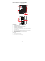
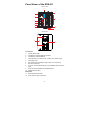
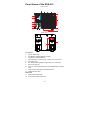
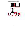
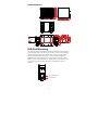
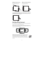
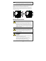
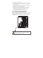
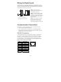
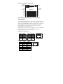
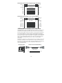
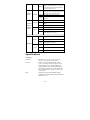
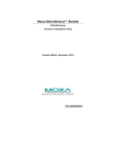
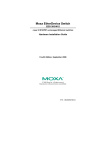
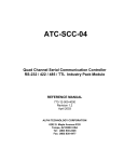
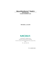
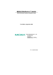
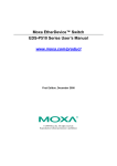
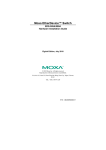
Moxa EtherDevice™ Switch
EDS-600 Series
Hardware Installation Guide
First Edition, August 2009
© 2009 Moxa Inc. All rights reserved.
Reproduction without permission is prohibited.
Fl.4, No.135, Lane 235, Pao-Chiao Rd. Shing Tien City, Taipei, Taiwan,
R.O.C.
TEL: +886-2-8919-1230
P/N: 1802006000010
Package Checklist
The Moxa EDS-600 series is shipped with the following items. If any of these
items is missing or damaged, please contact your customer service
representative for assistance.
y 1 EDS-600 EtherDevice Switch
y Hardware Installation Guide
y CD-ROM with User’s Manual and Windows utility
y Moxa product warranty statement
y RJ45 to DB9 console port cable
y Protective caps for unused ports
y Wall Mounting Kit (optional—must be ordered separately)
y Anti-Vibration Wiring Kit (optional, must be ordered separately)
Features
Advanced Industrial Networking Capabilities
y IPv6 ready (certified by the IPv6 Logo Committee).
y IEEE 1588 PTP (Precision Time Protocol) for precise time
synchronization of networks.
y Supports LLDP (Link Layer Discovery Protocol)
y DHCP Option 82 for IP address assignment with different policies.
y Supports Modbus/TCP industrial Ethernet protocol.
y Turbo Ring and Turbo Chain (< 20 ms recovery time at full load) and
STP/RSTP (IEEE 802.1w/D).
y IGMP snooping and GMRP for filtering multicast traffic.
y Port-based VLAN, IEEE 802.1Q VLAN, and GVRP to ease network
planning.
y QoS (IEEE 802.1p/1Q) and TOS/DiffServ to increase determinism.
y Port Trunking for optimal bandwidth utilization.
y IEEE 802.1X, HTTPS, and SSH to enhance network security.
y SNMPv1/v2c/v3 for different levels of network management.
y RMON for efficient network monitoring and proactive capability.
y Bandwidth management prevents unpredictable network status.
y Lock port function for blocking unauthorized access based on MAC
address.
y Port mirroring allows for online debugging.
y Automatic warning by exception through e-mail and relay output.
y Digital inputs to integrate sensors and alarms with IP networks.
-2-
Panel Views of the EDS-608
FRONT VIEW
8
1
2
4
7
6
8
5
3
REAR VIEW
10
9
Front Panel:
1.
System Status LEDs
2.
Fast Ethernet Interface Module port LEDs
3.
Fast Ethernet Interface Module
4.
Terminal block for 2 power inputs, 1 DI/DO, and 1 relay output
5.
Grounding screw
6.
DIP switches for Ring Master, Ring Coupler, and Turbo Ring
7.
RS-232 Console port
8. Screw to attach Fast Ethernet Interface Module
Rear Panel:
9.
DIN-Rail Attachment Plate
10. Screw holes for wall mounting kit
-3-
Panel Views of the EDS-611
FRONT VIEW
10
9
1
8
2
4
7
6
5
9
3
REAR VIEW
12
11
Front Panel:
1.
System Status LEDs
2.
Fast Ethernet Interface Module port LEDs
3.
Fast Ethernet Interface Module
4.
Terminal block for 2 power inputs, 1 DI/DO, and 1 Relay output
5.
Grounding screw
6.
DIP switches for Ring Master, Ring Coupler, and Turbo Ring
7.
8.
RS-232 Console port
G1 to G3: 10/100/1000 BaseT(X) or 100/1000Base SFP slot combo
ports
9.
Screw to attach Fast Ethernet Interface Module
10. Gigabit Ethernet LEDs
Rear Panel:
11. DIN-Rail Attachment Plate
12. Screw holes for wall mounting kit
-4-
Panel Views of the EDS-616
FRONT VIEW
8
1
2
4
7
6
8
5
3
REAR VIEW
9
10
Front Panel:
1.
System Status LEDs
2.
Fast Ethernet Interface Module port LEDs
3.
Fast Ethernet Interface Module
4.
Terminal block for 2 power inputs, 1 DI/DO, and 1 relay output
5.
Grounding screw
6.
DIP switches for Ring Master, Ring Coupler, and Turbo Ring
7.
RS-232 Console port
8. Screw to attach Fast Ethernet Interface Module
Rear Panel:
9.
DIN-Rail Attachment Plate
10. Screw holes for wall mounting kit
-5-
Panel Views of the EDS-619
FRONT VIEW
10
9
1
8
2
4
7
6
9
5
3
REAR VIEW
11
12
Front Panel:
1.
System Status LEDs
2.
Fast Ethernet Interface Module port LEDs
3.
Fast Ethernet Interface Module
4.
Terminal block for 2 power inputs, 1 DI/DO, and 1 relay output
5.
Grounding screw
6.
DIP switches for Ring Master, Ring Coupler, and Turbo Ring
7.
8.
RS-232 Console port
G1 to G3: 10/100/1000 BaseT(X) or 100/1000Base SFP slot combo
ports
9.
Screw to attach Fast Ethernet Interface Module
10. Gigabit Ethernet LEDs
Rear Panel:
11. DIN-Rail Attachment Plate
12. Screw holes for wall mounting kit
-6-
Mounting Dimensions (unit = mm)
EDS-608/EDS-611
Front View
Side View
Rear View
Panel Mounting Kit
Panel Mounting Kit
Rear View
DIN-Rail Attachment Plate
-7-
EDS-616/EDS-619
Front View
Side View
Rear View
Panel Mounting Kit
DIN-Rail Attachment Plate
Panel Mounting Kit
Rear View
DIN-Rail Attachment Plate
DIN-Rail Mounting
The aluminum DIN-Rail attachment plate should already be fixed to the back
panel of the EDS-600 when you take it out of the box. If you need to reattach
the DIN-Rail attachment plate to the EDS-600, be sure the spring-loaded
bracket is situated towards the bottom, as shown in the following figures.
STEP 1: If the spring-loaded bracket is locked in place, push the recessed
button to release it. Once released, you should feel some resistance from the
spring as you slide the bracket up and down a few millimeters in each
direction.
Spring-loaded bracket
Recessed button
-8-
STEP 2—Insert the top of the
DIN-Rail into the top slots on the
DIN-Rail attachment plate.
STEP 3—The DIN-Rail attachment
unit will snap into place as shown in
the following illustration.
DIN-Rail
DIN-Rail
To remove the Moxa EDS-600 switch from the DIN-Rail, use a screwdriver
to push down the spring-loaded bracket until it locks in place, as shown in the
following diagram. Next, rotate the bottom of the switch upwards and then
remove the switch from the DIN-Rail.
DIN-Rail
Wall Mounting (Optional)
For some applications, you will find it convenient to mount the EDS-600 on
the wall, as shown in the following illustrations:
STEP 1—Remove the aluminum DIN-Rail attachment plate from the rear
panel of the EDS-600, and then attach the wall mount plates with M3 screws,
as shown in the figure at the right.
WALL MOUNT KIT
WALL MOUNT KIT
REAR VIEW
STEP 2—Mounting the EDS-600 on the wall requires 4 screws.
Use the EDS-600, with wall mount plates attached, as a guide to
mark the correct locations of the 4 screws. The heads of the
screws should be less than 6.0 mm in diameter, and the shafts
should be less than 3.5 mm in diameter, as shown in the figure at
the right.
-9-
6.0 mm
3.5 mm
NOTE
Before tightening the screws into the wall, make sure the screw
head and shank size are suitable by inserting the screw through
one of the keyhole-shaped apertures of the Wall Mounting Plates.
Do not screw the screws in all the way—leave about 2 mm to allow room for
sliding the wall mount panel between the wall and the screws.
STEP 3—Once the screws are fixed to the wall, insert the four screw heads
through the wide parts of the keyhole-shaped apertures, and then slide the
EDS-600 downwards, as indicated in the figure at the right. Tighten the four
screws for more stability.
Wiring Requirements
WARNING
Do not disconnect modules or wires unless power has been
switched off or the area is known to be non-hazardous. The
devices may only be connected to the supply voltage shown on
the type plate. The devices are designed for operation with a
Safety Extra-Low Voltage. Thus, they may only be connected to
the supply voltage connections and to the signal contact with the
Safety Extra-Low Voltages (SELV) in compliance with IEC950/
EN60950-1/ VDE0805.
ATTENTION
This unit is a built-in type. When the unit is installed in another
piece of equipment, the equipment enclosing the unit must
comply with fire enclosure regulation IEC 60950-1/EN60950-1
(or similar regulation).
ATTENTION
Safety First!
Be sure to disconnect the power cord before installing and/or
wiring your Moxa EtherDevice Switch.
Calculate the maximum possible current in each power wire and
common wire. Observe all electrical codes dictating the
maximum current allowable for each wire size.
If the current goes above the maximum ratings, the wiring could
overheat, causing serious damage to your equipment.
- 10 -
Please read and follow these guidelines:
y Use separate paths to route wiring for power and devices. If power wiring
and device wiring paths must cross, make sure the wires are perpendicular
at the intersection point.
NOTE: Do not run signal or communications wiring and power wiring
through the same wire conduit. To avoid interference, wires with different
signal characteristics should be routed separately.
y You can use the type of signal transmitted through a wire to determine
which wires should be kept separate. The rule of thumb is that wiring
sharing similar electrical characteristics can be bundled together
y You should separate input wiring from output wiring
y We advise that you label the wiring to all devices in the system.
Grounding the Moxa EDS-600
EDS switches are designed to enhance EMS performance by grounding. EDS
switches come with metal DIN-Rail brackets for grounding the switches. For
optimal EMS performance, connect the chassis ground nut on the switch to
the grounding point.
ATTENTION
This product is intended to be mounted to a well-grounded
mounting surface such as a metal panel.
- 11 -
Wiring the Relay Contact
The EDS-600 has a set of relay outputs. The relay contact uses two of the
terminal block’s contacts located on the EDS-600’s front panel. Refer to the
next section for detailed instructions on how to connect the wires to the
terminal block connector, and how to attach the terminal block connector to
the terminal block receptor.
In this section, we illustrate the meaning of the two contacts used to connect
the relay contact.
FAULT:
The relay contacts of the 6-pin terminal block connector are used to detect
user-configured events. The three wires attached to the fault contacts form an
open circuit when a user-configured event is triggered. If a user-configured
event does not occur, the fault circuit remains closed.
The relay output has current carrying capacity of 1 A @ 24 VDC.
Relay Circuit Status when Power is On/Off
Power On
Power Off
COM & NC
COM & NO
COM & NC
COM & NO
Open Circuit
Short Circuit
Short Circuit
Open Circuit
Wiring the Redundant Power Inputs
The EDS-600 has two sets of power inputs, power 1 and power 2, which are
located on the EDS-600’s front panel. Power 1 is the bottom two contacts on
the upper 6-contact terminal block and power 2 is the top two contacts on the
lower 5-contact terminal block.
STEP 1: Insert the negative/positive DC
wires into the V-/V+ terminals,
respectively.
STEP 2: To keep the DC wires from
pulling loose, use a small flat-blade
screwdriver to tighten the wire-clamp
screws on the front of the terminal block
connector.
STEP 3: Insert the plastic terminal block
connector prongs into the terminal block
receptor, which is located on the
EDS-600’s front panel.
- 12 -
Wiring the Digital Inputs
The EDS-600 has one set of digital inputs (DIs). Each DI consists of two
contacts of the 5-pin terminal block connector on the EDS-600’s front panel,
which are used for the one DC input. The top and front views of one of the
terminal block connectors are shown here.
STEP 1: Insert the negative
(ground)/positive DI wires into the ┴
/I1 terminals, respectively.
y +13 to +30 V for state “1”
y -30 to +3 V for state “0”
y Max. input current: 8 mA
STEP 2: To keep the DI wires from
pulling loose, use a small flat-blade
screwdriver to tighten the wire-clamp
screws on the front of the terminal
block connector.
STEP 3: Insert the plastic terminal
block connector prongs into the
terminal block receptor, which is
located on the EDS-600’s front panel.
Communication Connections
EDS-600 series switches have different types of communication ports:
y 1 RJ45 console port (RS-232 interface).
y Up to 3 Gigabit combo 10/100/1000T(X) or 100/1000BaseSFP ports.
y 4-port Fast Ethernet interface modules that include 10/100BaseT(X) and
100BaseFX ports with SC/ST connectors.
RS-232 Connection
The EDS-600 has one RS-232 (10-pin RJ45) console port, located on the
front panel. Use either an RJ45-to-DB9 (see the following cable wiring
diagrams) to connect the EDS-600’s console port to your PC’s COM port.
You may then use a console terminal program, such as Moxa PComm
Terminal Emulator, to access the EDS-600’s console configuration utility.
RJ45 (10-pin) Console Port Pinouts
Pin
1
2
3
4
5
6
7
8
9
10
Description
-----DSR
RTS
-----TxD
RxD
GND
CTS
DTR
------
1
- 13 -
10
RJ45 (10-pin) to DB9 (F) Cable Wiring
Moxa
EtherDevice
Server
COM Port
RJ45 Plug Pin 1
RJ45
Connector
Female DB9
Connector
Cable Wiring
1
DCD
2
DSR
3
RTS
GND 4/7
5
TxD
6
RxD
8
CTS
9
DTR
1
6
7
5
3
2
8
4
DCD
DTR
CTS
GND
RxD
TxD
RTS
DSR
10/100/1000BaseT(X) Ethernet Port
Connection
The 10/100/1000BaseT(X) ports located on switch’s front panel are used to
connect to Ethernet-enabled devices. Most users will choose to configure
these ports for Auto MDI/MDI-X mode, in which case the port’s pinouts are
adjusted automatically depending on the type of Ethernet cable used
(straight-through or cross-over), and the type of device (NIC-type or
HUB/Switch-type) connected to the port.
In what follows, we give pinouts for both MDI (NIC-type) ports and MDI-X
(HUB/Switch-type) ports. We also give cable wiring diagrams for
straight-through and cross-over Ethernet cables.
10/100Base T(x) RJ45 Pinouts
MDI Port Pinouts
Pin
1
2
3
6
Signal
Tx+
TxRx+
Rx-
MDI-X Port Pinouts
Pin
1
2
3
6
8-pin RJ45
Signal
Rx+
RxTx+
Tx-
1
1000BaseT RJ45 Pinouts
Pin
1
2
3
4
5
6
7
8
MDI
BI_DA+
BI_DABI_DB+
BI_DC+
BI_DCBI_DBBI_DD+
BI_DD-
MDI-X
BI_DB+
BI_DBBI_DA+
BI_DD+
BI_DDBI_DABI_DC+
BI_DC-
1
- 14 -
8
8
RJ45 (8-pin) to RJ45 (8-pin) Straight-through Cable Wiring
Straight-Through Cable
Switch Port
RJ45
Connector
Tx+
TxRx+
RxDD+
DDDC+
DC-
NIC Port
RJ45 Plug Pin 1
RJ45
Connector
Cable Wiring
3
6
1
2
4
5
7
8
3
6
1
2
4
5
7
8
Rx+
RxTx+
TxDC+
DCDD+
DD-
RJ45 (8-pin) to RJ45 (8-pin) Cross-over Cable Wiring
Cross-Over Cable
Switch Port
(NIC Port)
RJ45 Plug Pin 1
RJ45
Connector
(Rx+)
(Rx-)
(Tx+)
(Tx-)
(DD+)
(DD-)
(DC+)
(DC-)
Tx+
TxRx+
RxDC+
DCDD+
DD-
Switch Port
(NIC Port)
RJ45
Connector
Cable Wiring
1
2
3
6
7
8
4
5
3
6
1
2
4
5
7
8
Rx+
RxTx+
TxDD+
DDDC+
DC-
(Tx+)
(Tx-)
(Rx+)
(Rx-)
(DC+)
(DC-)
(DD+)
(DD-)
100BaseFX or 1000BaseSFP Fiber Port
The Gigabit Ethernet ports on the EDS-600 series are SFP slots, which require
100BaseFX SFP or Gigabit mini-GBIC fiber transceivers to work properly.
Moxa provides complete transceiver models for various distance requirements.
The concept behind the LC port and cable is quite straightforward. Suppose
you are connecting devices I and II. Unlike electrical signals, optical signals do
not require a circuit in order to transmit data. Consequently, one of the optical
lines is used to transmit data from device I to device II, and the other optical
line is used to transmit data from device II to device I, for full-duplex
transmission.
Remember to connect the Tx (transmit) port of device I to the Rx (receive) port
of device II, and the Rx (receive) port of device I to the Tx (transmit) port of
device II. If you make your own cable, we suggest labeling the two sides of the
same line with the same letter (A-to-A and B-to-B, as shown below, or
A1-to-A2 and B1-to-B2).
LC-Port Pinouts
LC-Port to LC-Port Cable Wiring
A
A
Tx
B
B
Cable Wiring
Rx
A
B
A
B
- 15 -
ATTENTION
This is a Class 1 Laser/LED product. To avoid causing serious
damage to your eyes, do not stare directly into the laser beam.
Turbo Ring DIP Switch Settings
EDS-600 series switches are managed redundant plug-and-play Ethernet
switches. The proprietary Turbo Ring protocol was developed by Moxa to
provide better network reliability and faster recovery time. Moxa Turbo Ring’s
recovery time is less than 300 ms (Turbo Ring) or 20 ms (Turbo Ring
V2) —compared to a 3- to 5-minute recovery time for commercial
switches—decreasing the possible loss caused by network failures in an
industrial setting.
Four DIP switches are located on the top panel of the EDS-600 to allow users
to set up Turbo Ring easily within seconds. If you do not want to use a
hardware DIP switch to set up Turbo Ring, you can use a web browser, Telnet,
or console to disable this function.
NOTE
Refer to the Turbo Ring DIP Switch section and Using
Communication Redundancy section in the User’s Manual for
detailed information about the settings and usage of Turbo Ring
and Turbo Ring V2.
EDS-600 Series DIP Switches
------
1
MASTER
2
COUPLER
3
TURBO
RING
4
The default setting for each DIP Switch is OFF. The
following table explains the effect of setting the DIP
Switch to the ON position.
“Turbo Ring” DIP Switch Settings
DIP 1
DIP 2
DIP 3
DIP 4
ON: Enables this ON: Enables the
EDS as the Ring default “Ring
Master.
Coupling” ports.
ON: Activates
DIP switches 1,
2, 3 to configure
“Turbo Ring”
settings.
OFF: Do not use
this EDS as the
ring coupler.
OFF: DIP
switches 1, 2, 3
will be disabled.
Reserved for
future use.
OFF: This EDS
will not be the
Ring Master.
- 16 -
“Turbo Ring V2” DIP Switch Settings
DIP 1
DIP 2
DIP 3
DIP 4
ON: Enables the
default “Ring
Coupling
(backup)” port.
ON: Enables this
EDS as the Ring
Master.
ON: Enables the
default “Ring
Coupling” port.
ON: Activates
DIP switches 1,
2, 3 to configure
“Turbo Ring V2”
settings.
OFF: Do not use
this EDS as a
ring coupler.
OFF: DIP
switches 1, 2, 3
will be disabled.
OFF: Enables the OFF: This EDS
default “Ring
will not be the
Coupling
Ring Master.
(primary)” port.
NOTE
You must enable the Turbo Ring function first before using the DIP
switch to activate the Master and Coupler functions.
NOTE
If you do not enable any of the EDS-600 switches to be the Ring
Master, the Turbo Ring protocol will automatically choose the
EDS-600 with the smallest MAC address range to be the Ring
Master. If you accidentally enable more than one EDS-600 to be
the Ring Master, these EDS-600 switches will auto-negotiate to
determine which one will be the Ring Master.
LED Indicators
The front panel of the EDS-600 contains several LED indicators. The
function of each LED is described in the following table:
LED
Color
PWR1
AMBER
PWR2
FAULT
MSTR/
HEAD
State
Description
Main System
Power is being supplied to power input
On
PWR1.
Off
Power is not being supplied to power
input PWR1.
On
Power is being supplied to power input
PWR2.
Off
Power is not being supplied to power
input PWR2.
On
When the corresponding PORT alarm is
enabled, and a user-configured event is
triggered.
Off
When the corresponding PORT alarm is
enabled and a user-configured event is
not triggered, or when the corresponding
PORT alarm is disabled.
On
When the EDS-600 is set as the Master
of the Turbo Ring or is set as the Head of
the Turbo Chain.
AMBER
RED
GREEN
- 17 -
When the EDS-600 is set as the Ring
Master of the Turbo Ring or as the Head
Blinking
of the Turbo Chain and the Turbo Ring
or Turbo Chain is down.
On
CPLR/
TAIL
G1/G2/G3
GREEN
When the EDS-600 coupling function is
enabled to form a back-up path or if it is
set as the Tail of the Turbo Chain.
Blinking When the Turbo Chain is down.
Off
To disable the EDS-600’s coupling
function.
On
10/100 Mbps link is active.
AMBER Blinking Data is being transmitted at 10/100
Mbps.
(EDS-611/
EDS-619
only)
GREEN
Off
10/100 Mbps link is inactive.
On
1000 Mbps link is active.
Blinking Data is being transmitted at 1000 Mbps.
Off
1000 Mbps link is inactive.
Interface Module
On
10 Mbps link is active.
AMBER Blinking Data is being transmitted at 10 Mbps.
Off
10 Mbps link is inactive.
On
100 Mbps link is active.
10/100M
Green
Blinking Data is being transmitted at 100 Mbps.
Off
100 Mbps link is inactive.
Specifications
Technology
Standards
IEEE802.3, 802.3u, 802.3x, 802.1D, 802.1w,
802.1Q, 802.1p, 802.1X, 802.3ad, 802.3z
Protocols
IGMP V1/V2 device, GMRP, GVRP, SNMP
V1/V2c/V3, DHCP Server/Client, BootP, TFTP,
DHCP Option66.67.82, SSH, MODBUS/TCP,
SNMP INFORM, SNTP, SMTP, RARP, RMON
MSTR/HEAD, CPLR/TAIL, 10/100/1000M (GB
port), 10/100M (Module TX/FX port), IEEE 1588
PTP, and IPv6
MIB
MIB-II, Ethernet-like MIB, P-BRIDGE MIB,
Q-BRIDGE MIB, Bridge MIB, RSTP MIB, RMON
MIB Group 1,2,3,9
- 18 -
Interface
RJ45 Ports
10/100/1000BaseT(X) auto negotiation speed, F/H
duplex mode, and auto MDI/MDI-X connection
Fiber Ports
Optional 100/1000Base SFP modules
Console Port
RS-232 (10-pin RJ45)
System LED Indicators
PWR1, PWR2, FAULT, MSTR/HEAD,
CPLR/TAIL, G1, G2, G3
Module LED Indicators
10/100M for TP port, 100M for Fiber port
Alarm Contact
Two relay outputs with current carrying capacity of
1 A @ 24 VDC
Digital Input
Two inputs with the same ground, but electrically
isolated from the electronics
• For state “1”: +13 to +30 V
• For state “0”: -30 to +3 V
• Max. input current: 8 mA
Power
Input Voltage
12/24/48 VDC, redundant inputs
Input Current (@24V)
EDS-608: 0.16A
EDS-611: 0.31A
EDS-616: 0.25A
EDS-619: 0.31A
Connection
Two removable 5-pin and 6-pin terminal blocks
Overload Current
Protection
Present
Reverse Polarity
Protection
Present
Mechanical
Casing
IP30 protection, metal case
Dimensions (W × H × D) EDS-608/611:
124.9 x 151 x 157.2 mm (4.92 x 5.95 x 6.19 in)
EDS-616/619:
185 x 151 x 157.2 mm (7.28 x 5.95 x 6.19 in)
Weight
EDS-608: 2.08 kg
EDS-611: 2.26 kg
EDS-616: 2.78 kg
EDS-619: 2.95 kg
Installation
DIN-Rail, Wall Mounting Kit (optional kit) ,
Anti-Vibration Wiring Kit (optional)
Environment
Operating Temperature
0 to 60°C (32 to 140°F), standard models
-40 to 75°C (-40 to 167°F) for -T models
Storage Temperature
-40 to 85°C (-40 to 185°F)
Ambient Relative
Humidity
5 to 95% (non-condensing)
Regulatory Approvals
Safety
UL 508(Pending) , EN60950-1(Pending)
- 19 -
Hazardous Location
UL/cUL Class I, Division 2, Groups A, B, C, and D;
ATEX Zone 2, Ex nC nL IIC T4 (Pending)
EMI
FCC Part 15, EN61000-6-4
EMS
EN61000-6-2
EN61000-4-2 (ESD),
> level 2 for multi-mode models with
ST connectors
> level 3 for all other models
EN61000-4-3 (RS), Level 3
EN61000-4-4 (EFT), Level 2
EN61000-4-5 (Surge), Level 3
EN61000-4-6 (CS), Level 3
EN61000-4-8
EN61000-4-12
EN61000-4-29
Maritime
DNV (Pending), GL (Pending), ABS (Pending),
LR (Pending), NKK (Pending)
Shock
IEC60068-2-27
Free Fall
IEC60068-2-32
Vibration
IEC60068-2-6
WARRANTY
5 years
Technical Support Contact Information
www.moxa.com/support
Moxa Americas:
Toll-free: 1-888-669-2872
Tel:
+1-714-528-6777
Fax:
+1-714-528-6778
Moxa China (Shanghai office):
Toll-free: 800-820-5036
Tel:
+86-21-5258-9955
Fax:
+86-10-6872-3958
Moxa Europe:
Tel:
+49-89-3 70 03 99-0
Fax:
+49-89-3 70 03 99-99
Moxa Asia-Pacific:
Tel:
+886-2-8919-1230
Fax:
+886-2-8919-1231
- 20 -