1
Safety • Assembly • Operation • Adjustment • Maintenance • Troubleshooting
A
O
• Warranty
AL
ii
ii
_i_i_i_ii _ iiii
ii_i_i!i_!i
i!II_
Transmatic Lawn Tractor-
Models 760=779
iMPORTANT
READ SAFETY
RULES AND iNSTRUCTiONS
CAREFULLY
BEFORE
OPERATION
Warning: This unit is equippedwith an internalcombustionengineand shouldnot be usedon or nearany unimprovedforest-covered,brushcoveredor grass-coveredland unlesstheengine'sexhaustsystemis equippedwith a sparkarrestermeetingapplicablelocalor statelaws(if any).
If a sparkarresteris used,it shouldbe maintainedin effectiveworkingorder by the operator.In theState of Californiathe aboveis requiredbylaw
(Section4442 of the CaliforniaPublicResourcesCode). Otherstatesmay havesimilarlaws.Federallaws applyon federallands.A sparkarrester
for the muffleris availablethroughyour nearestengineauthorizedservicedealeror contactthe servicedepartment,RO. Box361131Cleveland,
Ohio 44136-0019.
PRINTEDIN U.S.A.
MTD LLC, P.O. BOX 361131 CLEVELAND, OHIO 44136-0019
FORMNO.769-01598B
01/06/2006
This Operator's Manual is an important part of your new lawn tractor, it will help you assemble,
prepare and maintain the unit for best performance.
Please read and understand what it says.
Table of Contents
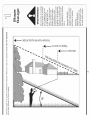
Slope Gauge .......................................................
Safe Operation Practices ...................................
Setting UpYour Lawn Tractor ............................
Operating Your Lawn Tractor ...........................
Adjusting Your Lawn Tractor ............................
3
4
8
12
20
Maintaining Your Lawn Tractor ........................
22
Off-Season Storage / Attachments ................. 28
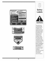
Safety Labels ....................................................
29
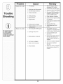
Trouble Shooting ..............................................
30
Warranty ..............................................
Back Page
Finding and Recording Model Number
BEFOREYOU START ASSEMBLING
YOUR NEW EQUIPMENT,
please locate the model plate on the equipment and copy the
information to the sample model plate provided to the right.
You can locate the model plate by looking beneathe the seat.
This information will be necessary to use the manufacturer's
web site and/or obtain assistance from the Customer Support
Department or an authorized service dealer.
Model Number
Serial Number
MTD LLC
www.mtdproducts.com
P.O= BOX
CLEVELAND,
330-220-4683
800-800-7310
361131
OH 44136
Customer Support
Please do NOTretum
purchased,
without
the unit to the retailer from which it was
first contacting
Customer
Support.
If you have difficulty assembling this product or have any questions regardingthe controls, operation,or maintenanceof this
unit, you can seek help from the experts. Choose from the options below:
1. Visit mtdproducts.com.
Click on the Service & Support menu option.
2. Phone a Customer Support Representative at 1 (800) 800-7310.
3. The engine manufacturer is responsiblefor all engine-related issues with regards to performance, power-rating,specifications, warranty and service. Please refer to the engine manufacturer'sOwner's/Operator's Manual, packed separatelywith
your unit, for more information.
MTD/n_er_@_i®a_
Award
Wi_n i_g ?rd_s_ts
?riv®cy Pd_y
O_r Com?_ay
o_r_,qo_
_
Suppo_±
Product. Registration
Product Menu
2
O
Sight and hold this levelwith a vertical tree...
o
1=
o
>:.
(13
O3
(13
(13
OO
O
(-O5
E
also
O
(13
(13
o3
(13
OO
o3
I
(13
E
(]3
(13
o
o5
(13
OO
O3
(13
-5
C5
O3
('5
O
O3
O5
(13
O
E
t"b
(13
O9
15°
WARNING: Engine Exhaust, some of its constituents, and certain vehicle components contain or emit chemicals known to State of Californiato cause cancer and
birth defects or other reproductiveharm.
DANGER: This machine was built to be operated according to the rules for safe operation in this
manual. As with any type of power equipment, carelessness or error on the part of the operator can
result in serious injury. This machine is capable of amputating hands and feet and throwing objects.
Failureto observe the following safety instructions could result in serious injury or death.
Practices
WARNING
This symbol points
out important safety
instructionswhich, if
not followed, could
endangerthe personal
safety and/or property
ofyourself and others.
Read and follow all
I instructions in this manual before attempting to
operate this machine.
tFailureto comply with
hese instructions may
result in personal injury.
When you see this
symbol.
HEED iTS WARNING
Your
Responsibility
Restrict the use
of this power machine
to persons who read,
understand
and follow the warnings
and instructions
in this manual
Children
Operation
1. Tragicaccidentscanoccur if the operatoris not
alertto the presenceof children.Childrenare often
attractedto themachineand the mowingactivity.
Theydo not understandthe dangers.Neverassume
that childrenwill remainwhereyou last sawthem.
a. Keepchildrenout of the mowingarea and in
watchfulcare of a responsibleadultother than
the operator.
b. Be alert and turnmachineoff ifa childenters
the area.
Safe Handling of Gasoline:
1. Toavoid personalinjuryor propertydamageuse
extremecare in handlinggasoline.Gasolineis
extremely flammableand the vapors are explosive. Seriouspersonalinjurycan occurwhengasoline
isspilledon yourselfor yourclotheswhichcan ignite.
Washyourskin and changeclothesimmediately.
a. Use onlyan approvedgasolinecontainer.
b. Neverfill containersinsidea vehicleor on a
truckor trailerbed with a plasticliner.Always
c. Beforeand while backing,lookbehindand
placecontainerson the groundawayfrom
downfor smallchildren.
yourvehiclebeforefilling.
d. Nevercarry children,evenwith the blade(s)
c. Whenpractical,removegas-powered
shutoff.They mayfalloff and be seriously
equipmentfromthe truckor trailerand refuelit
injuredor interferewith safemachineoperation.
on the ground.If this isnotpossible,then
e. Use extremecarewhenapproachingblind
refuelsuch equipmenton a trailerwith a
corners,doorways,shrubs,trees or other
portablecontainer,ratherthan froma gasoline
objectsthat may blockyourvision of a child
dispensernozzle.
whomay run intothe machine.
d. Keepthe nozzlein contactwith the rimof
f. To avoid back-over accidents, always
the fueltank or containeropeningat all
disengagethe cuttingblade(s) before
timesuntilfuelingiscomplete.Donot usea
shiftinginto Reverse.if equipped,the
nozzlelock-opendevice.
"Reverse CautionMode"shouldnot be
e. Extinguishall cigarettes,cigars,pipesand
used when childrenor others are around.
othersourcesof ignition.
g. Keepchildrenaway from hotor running
f. Neverfuel machineindoors.
engines.They can sufferburnsfroma hot
g. Neverremovegas cap or add fuel whilethe
muffler.
engineishot or running.Allowengineto cool
h. Removekeywhenmachineis unattendedto
at least two minutesbeforerefueling.
preventunauthorizedoperation.
h. Neveroverfill fuel tank.Fill tank to no more
2. Neverallowchildrenunder 14 yearsold to operate
than1/2inchbelowbottomof filler neck to
the machine.Children14years old and overshould
allowspacefor fuel expansion.
readand understandthe operationinstructions
and
i. Replacegasolinecapand tighten securely.
safety rulesinthis manualand shouldbe trainedand
j. If gasolineis spilled,wipe it off theengine
supervisedbya parent.
and equipment.Moveunit to anotherarea.
Wait5 minutesbeforestartingtheengine.
k. Toreducefirehazards,keepmachinefreeof
grass,leaves,or otherdebris build-up.Clean
up oil or fuel spillageand removeanyfuel
soakeddebris.
I. Neverstorethe machineor fuel container
insidewherethere is an open flame,spark
or pilot lightas on a waterheater,space
heater,furnace,clothesdryeror other gas
appliances.
m. Allowa machineto cool at least five minutes
beforestoring.
4
....................................................
GeneralOperation:
14.Watchfor traffic whenoperatingnearor crossing
roadways.This machineis not intendedfor useon
anypublic roadway.
15.Do notoperatethe machinewhileunderthe influenceof alcoholor drugs.
16.Mowonly in daylightor good artificiallight.
17.Nevercarry passengers.
18.Disengageblade(s)beforeshiftinginto reverse.
Back up slowly.Alwayslookdownand behindbefore
and whilebackingto avoida back-overaccident.
19.Slowdownbeforeturning.Operatethe machine
smoothly.Avoiderraticoperationand excessive
speed.
20.Disengageblade(s),set parkingbrake,stopengine
and wait untilthe blade(s)cometo a completestop
beforeremovinggrass catcher,emptyinggrass,
uncloggingchute,removingany grassor debris,or
makinganyadjustments.
21.Neverleavea runningmachineunattended.Always
turnoff blade(s), placetransmissionin neutral,set
parkingbrake,stop engineand removekey before
dismounting.
22.Useextracare whenloadingor unloadingthe
machineintoa traileror truck. This unit shouldnot
be drivenup or downramp(s),becausethe unit
couldtip over,causingseriouspersonalinjury.The
unit mustbe pushedmanuallyon ramp(s)to load or
unloadproperly.
23.Mufflerand enginebecomehotand can causea
burn.Do nottouch.
1. Read,understand,and followall instructionson the
machineand in the manual(s)beforeattemptingto
assembleand operate.Keepthis manualin a safe
placefor future and regularreferenceand for ordering
replacementparts.
2. Be familiarwith all controlsandtheir properoperation.
Knowhow to stopthe machineand disengagethem
quickly.
3, Neverallowchildrenunder 14yearsold to operate
this machine.Children14years old and overshould
readand understandthe operationinstructionsand
safety rulesin this manualand shouldbe trainedand
supervisedby a parent.
4. Neverallowadults to operatethis machinewithout
proper instruction.
5. To helpavoidblade contactor a thrownobject injury,
keep bystanders,helpers,childrenand petsat least
75 feet fromthe machinewhileit is in operation.Stop
machineif anyoneenters thearea.
6. Thoroughlyinspectthearea wheretheequipmentis to
be used. Removeall stones,sticks,wire,bones,toys,
and otherforeignobjectswhichcouldbe pickedup
and thrown bythe blade(s).Thrownobjectscancause
seriouspersonalinjury.
7. Planyourmowingpatternto avoiddischargeof
materialtowardroads,sidewalks,bystandersand the
like. Also,avoiddischargingmaterialagainsta wall or
obstructionwhich maycause dischargedmaterialto
ricochetback towardthe operator.
8. Alwayswear safetyglassesor safetygogglesduring
24.Checkoverheadclearancescarefullybeforedriving
operationand while performingan adjustmentor
under lowhangingtreebranches,wires,dooropenrepairto protectyoureyes.Thrownobjectswhich
ingsetc., wheretheoperatormaybe struckor pulled
ricochetcancause seriousinjuryto the eyes.
fromthe unit,which couldresult in seriousinjury.
9. Wearsturdy,rough-soledwork shoesand close-fitting 25.Disengageall attachmentclutches,depressthe
slacks and shirts. Loosefittingclothesandjewelry
brakepedalcompletelyand shift into neutralbefore
can be caught in movableparts.Neveroperatethis
attemptingto startengine.
machinein barefeet or sandals.
26.Yourmachineisdesignedto cut normalresidential
10.Be awareof the mowerand attachmentdischarge
grassof a heightno morethan 10".Do notattemptto
directionand do not pointit at anyone.Donot operate
mowthroughunusuallytall, dry grass (e.g.,pasture)
the mowerwithoutthe dischargecoveror entiregrass
or pilesof dry leaves.Dry grass or leavesmay
catcherin its properplace.
contactthe engineexhaustand/orbuild up on the
mowerdeck presentinga potentialfire hazard.
11.Donot put handsor feet near rotatingpartsor under
27.Use onlyaccessoriesand attachmentsapprovedfor
the cuttingdeck. Contactwith the blade(s)can
amputatehandsand feet.
this machinebythe machinemanufacturer.Read,
understandand followall instructionsprovidedwith
12.A missingor damageddischargecovercan cause
the approvedaccessoryor attachment.
blade contactor thrown objectinjuries.
13.Stop the blade(s)whencrossinggraveldrives,walks, 28.Data indicatesthat operators,age 60 yearsand
above,are involvedin a largepercentageof riding
or roadsand whilenot cuttinggrass.
mower-relatedinjuries.Theseoperatorsshould
evaluatetheirability to operatethe ridingmower
safelyenoughto protectthemselvesand othersfrom
seriousinjury.
29.If situationsoccurwhich are not coveredin this
manual,usecareand good judgment.Contactyour
customerservicerepresentativefor assistance.
WARNING
This symbol points
out important safety
instructions which, if
not followed, could
endanger the personal
safety and/or property
of yourself and others.
Read and follow all
instructions in this manual before attempting to
operate this machine.
Failureto comply with
these instructions may
result in personal injury.
When you see this
symbol.
HEED ITS WARNING
Your
Responsibility
Restrictthe use
of this power machine
to persons who read,
understand
and follow the warnings
and instructions
in this manual
5
Thissymbolpoints
outimportant
safety
instructions
which,if
notfollowed,could
endanger
thepersonal
i safetyand/orproperty
ofyourselfandothers.
Readandfollowall
instructions
inthismanualbeforeattempting
to
I operatethismachine.
I Failuretocomplywith
theseinstructions
may
i resultin personal
injury.
Whenyouseethis
symbol.
Slope Operation:
Do Not:
Slopesare a majorfactor relatedto loss of controland
tip-overaccidentswhich can resultin severeinjuryor
death.All slopesrequireextracaution.If youcannot
back up the slopeor if youfeel uneasyon it, do notmow
it.
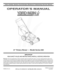
Foryour safety,usethe slopegaugeincludedas partof
this manualto measureslopesbeforeoperatingthis unit
on a slopedor hillyarea. If the slopeis greaterthan 15
degreesas shownon theslopegauge,do notoperate
this unit on that area or seriousinjurycouldresult.
DO:
1. Do notturn on slopesunlessnecessary;then,turn
slowlyand graduallydownhill,if possible.
2. Do not mownear drop-offs,ditchesor embankments.
Themowercouldsuddenlyturnoverif a wheel is over
the edgeof a cliff, ditch,or if an edge cavesin.
3. Do nottry to stabilizethe machineby puttingyourfoot
on the ground.
4. Do not usea grasscatcheron steep slopes.
5. Do not mowon wet grass. Reducedtractioncould
causesliding.
6. Do not shiftto neutraland coastdownhill.Over-speeding may causethe operatorto losecontrol of the
machineresultingin seriousinjuryor death.
7. Do nottow heavy pull behindattachments(e.g.loaded
dumpcart, lawnroller,etc.)on slopesgreaterthan
5 degrees.Whengoingdown hill,the extra weight
tendsto pushthe tractorand may causeyou to loose
control.(e.g. tractormayspeedup, brakingand steering ability are reduced,attachmentmayjack-knifeand
causetractorto overturn).
1. Mow up and downslopes,notacross. Exercise
extremecautionwhenchangingdirectionon slopes.
2. Watchfor holes, ruts,bumps,rocks,or other hidden
objects.Uneventerraincouldoverturnthe machine.
Tallgrasscan hide obstacles.
3. Use slow speed.Choosea low enoughspeed
settingso that youwill not haveto stopor shift while
on the slope.Tires may losetractionon slopeseven
thoughthe brakesare functioningproperly.Always
keepmachinein gear whengoingdown slopesto
take advantageof engine brakingaction.
4. Followthe manufacturer'srecommendations
for
wheelweightsor counterweightsto improvestability.
5. Use extracare with grasscatchersor otherattachments.Thesecanchangethe stabilityof the
machine.
Towing:
1. Towonlywith a machinethat hasa hitch designedfor
towing.Donot attachtowedequipmentexceptat the
hitch point.
2. Followthe manufacturersrecommendationfor weight
limitsfor towedequipmentand towingon slopes.
3. Neverallowchildrenor othersin or on towedequipment.
6. Keepall movementon the slopesslowand gradual.
Do not makesuddenchangesin speedor direction.
Rapidengagementor brakingcouldcausethe front
of the machineto lift and rapidlyflip overbackwards
whichcouldcause seriousinjury.
7. Avoidstartingor stoppingon a slope.If tires lose
traction,disengagethe blade(s)and proceedslowly
straightdownthe slope.
4. On slopes,the weightof the towedequipmentmay
causeloss of tractionand loss of control.
5. Travelslowlyand allowextra distanceto stop.
6. Do not shiftto neutraland coastdownhill.
i HEED ITSWARNING
Your
i Responsibility
Restrict the use
of this power machine
to persons who read,
understand
and follow the warnings
and instructions
in this manual
6
Service
10.Neverattemptto makeadjustmentsor repairsto the
machinewhilethe engine isrunning.
1. Neverrun an engineindoorsor in a poorlyventilated
11.Grasscatchercomponents
and the discharge
area. Engineexhaustcontainscarbonmonoxide,an
coverare
subjectto
wearand
damagewhich could
odorless,and deadlygas.
exposemovingpartsor allowobjectsto be thrown.
2. Beforecleaning,repairing,or inspecting,makecertain
Forsafety protection,frequentlycheckcomponents
the blade(s)and all movingparts havestopped.
and replaceimmediatelywith originalequipment
Disconnectthe sparkplug wireand groundagainstthe
manufacturer's(O.E.M.)parts only,listed in this
engineto preventunintendedstarting.
manual."Useof parts which do not meetthe original
3. Periodicallycheckto make surethe bladescome to
equipmentspecificationsmay leadto improper
completestop withinapproximately(5) five seconds
performanceand compromisesafety!"
after operatingthe bladedisengagementcontrol.If the
12.Do notchangethe enginegovernorsettingsor
bladesdo notstop within thethis timeframe,yourunit
over-speedthe engine.Thegovernorcontrolsthe
shouldbe servicedprofessionallyby an authorized
maximumsafe operatingspeedof the engine.
MTDServiceDealer.
13.Maintainor replacesafety and instructionlabels,as
4. Checkbrakeoperationfrequentlyas it is subjectedto
necessary.
wearduring normaloperation.Adjustand serviceas
14.Observeproperdisposallawsand regulationsfor
required.
gas, oil,etc. to protecttheenvironment.
5. Checkthe blade(s)and enginemountingbolts at
frequentintervalsfor propertightness.Also,visually
inspectblade(s)for damage(e.g.,excessivewear,
bent, cracked). Replacethe blade(s)with theoriginal
equipmentmanufacturer's(O.E.M.)blade(s)only,
listed inthis manual."Useof partswhich do not meet
the originalequipmentspecificationsmaylead to
improperperformanceand compromisesafety!"
6. Mowerbladesare sharp.Wrapthe bladeor wear
gloves,and useextra cautionwhenservicingthem.
7. Keepall nuts, bolts,and screwstight to be surethe
equipmentis insafe workingcondition.
8. Nevertamperwith the safety interlocksystemor other
safety devices.Checktheir properoperationregularly.
9. After strikinga foreignobject,stop the engine,
disconnectthe spark plug wire(s)and groundagainst
the engine.Thoroughlyinspectthe machinefor any
damage.Repairthe damagebeforestartingand
operating.
This symbol points
out important safety
instructions which, if
not followed, could
endangerthe personal
safety and/or property
of yourselfand others.
Read and follow all
instructions in this manual before attempting to
operate this machine.
Failureto comply with
these instructions may
result in personal injury.
When you see this
symbol.
HEED iTS WARNING
Your
Responsibility
Restrictthe use
of this power machine
to personswho read.
understand
and follow the warnings
and instructions
in this manual
7
NOTE:This OperatorsManualcoversa rangeof product
specificationsfor variousmodels.Characteristicsand featuresdiscussedand/orillustratedin this manualmay not
be applicableto all models.MTDLLCreservesthe right
to changeproductspecifications,designsand equipment
withoutnotice and withoutincurringobligation.
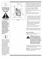
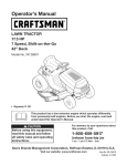
RubberBoot
Attaching
the Battery
Cables
NOTE:Somemodelsare shippedwith the batterycables
alreadyconnected.
Tractor
NOTE:Thepositivebatteryterminalis markedPos. (+).
Thenegativebatteryterminalis markedNeg. (-).
Use extreme care
Figure 1
when
handling
•
Thepositivecable(heavy redwire) is securedto the
positivebatteryterminal(+)with a hexbolt and hex
nut at thefactory.Makecertainthat the rubberboot
coversthe terminalto help protectit fromcorrosion.
•
Removethehex boltand hexnut fromthe negative
cable.
•
Removetheblack plasticcover,if present,from the
negativebatteryterminaland attachthe negative
cable(heavy blackwire)to the negativebattery
terminal(-) withthe bolt and nut.
•
Makecertain thehold-downstrap is in positionover
the battery,securingit in place. See Figure1.
gaso nel
Gasoline
extremely flammable
and the vapors are
explosive: Never fuel
machine indoors
NOTE:If the batteryis putinto serviceafter the date
shownon top of battery,chargethe batteryas instructed
on page 24 of this manualprior to operatingthe tractor.
or while the engine
is hot or running,
Extinguish cigarettes,
cigars, pipes, and
other
sources
of
Gas and Oil Fill-up
ignitionl
Thegasolinetank is locatedunderthe hood and hasa
capacityof 1-1/2gallons.Donot overfill.
WARNING: Use extreme care
when handling gasoline. Gasoline is extremely flammable and
the vapors are explosive. Never
fuel machine indoors or while the
NOTE: This Operators
Manual Coversa range
of produCtspecifications
for VariousmodelS:
engine is hot or running. Extinguish cigarettes, cigars, pipes,
and other sources of ignition.
Characteristics and
featuresdiscussed
and/or illustrated in
i
Servicethe enginewith gasolineand oil as instructedin
the separateEngineOperator/OwnerManualpackedwith
yourtractor.Readinstructionscarefully.
s manualmay not
applicable toall models:
MTD LLC reservesthe
IMPORTANT:Yourtractoris shippedwith motoroil in the
engine.However,you MUSTcheckthe oil levelbefore
operating.Be careful notto overfill.
right to change product
specifications, (Jesigns
and equipment without
notice and without incuri[ing obligatiOnl
8
Shipping
Brace Removal
f
WARNING: Make sure the riding
mower's engine is off, remove the
ignition key, and set the parking
brake before removing the shipping brace.
•
TractOr
Locatethe shippingbrace,ifpresent,and accompanyingwarningtag foundon the rightside of the mower,
betweenthe dischargechuteand thecuttingdeck.
See Figure2.
• Whileholdingthe dischargechute with yourleft hand,
removethe shippingbracewith your righthandby
graspingitbetweenyour thumband indexfingerand
rotatingitclockwise.
Figure 2
WARNING: The shipping brace,
used for packaging purposes
only, must be removed and discarded before operating your
riding mower.
Make sure the riding
mower's engine is
off, remove the ignition key, and set the
parking brake before
removingthe shipping
brace.
WARNING: The mowing deck is
capable of throwing objects. Failure to operate the riding mower
without the discharge cover in the
proper operating position could
result in serious personal injury
and/or property damage.
Attaching
The Steering
WARNING
The shipping brace,
used for packaging
purposes only, must
be removed and
discarded before
operating your riding
mower.
Wheel
If the steeringwheelforyour tractordid notcome
attached,the hardwarefor attachingit hasbeen packed
within the steeringwheel,beneaththe steeringwheel
cap. Carefullypry off the steeringwheelcapand remove
the hardware.
Figure 3
The mowing deck is
capable of throwing
objects. Failure to
operate the riding
mower without the
discharge cover in
the proper operating
position could result
in serious personal
injury and/or property
damage.
NOTE:Thereare two differentstylesof steeringwheel
cap. See Figure3. Styles vary by model.
1. With the wheels of the tractor pointingstraight
forward, placethe steeringwheeloverthe steering
shaft.
2. Placethe washer(with thecuppedsidedown)over
the steeringshaftand securewith the hex bolt. See
Figure3.
3. Placethe steeringwheelcap overthe centerof the
steeringwheeland pushdownwarduntilit"clicks"into
place.
9
Attaching
The Seat
Seatstyles vary bytractormodeland thereare three
differentstyles available:
• StandardAdjustment
•
QuickAdjustment&
•
KnobAdjustment
If the seatfor yourtractordid notcome attached,referto
Figure4, Figure5, and Figure6 to identifyyourtractor's
seat styleand followthe applicableinstructionsbelowto
attachit.
Figure 4
WARNING
NOTE:Forshippingreasons,seatsare eitherfastened
to the tractorseat'spivot bracketwith a plastictie, or
mountedbackwardto the pivot bracket.Ineithercase,
freethe seat form its shippingpositionand removethe
two hex screws(or knobs,on modelsso equipped)from
the bottomof seatbeforeproceedingwith applicable
instructionsbelow.
Standard Adjustment Seat
1. Positionthe shoulderscrews(foundon the baseof the
seat) insidetheslot openingsin the seat pivot bracket.
Figure4.
Before operatingthis
machine,make sure
the seat is engaged in
the seat stop; stand
2. Slide the seatslightlyrearwardin the seat pivot
bracket,liningup the rearslots in the pivot bracket
with the remainingtwo holesin the seat'sbase.
and
pu,back
onseat
3. Selectdesiredpositionforthe seat,and securewith
the two hex screwsremovedearlier.See Figure4.
behind
themachine
fu,yengaged
Quick Adjustment Seat
intostop:
NOTE:If your seatwas shippedmountedbackwardson
the seat pivotbracket,pull outthe tab foundon the seat
stop and hold it open whileslidingthe seatoff the seat
pivot bracket.See Figure5.
Figure 5
NOTE: Forsh pping rea:
s0nsl Seatsareeither
1. Line up the plasticseat spacerswith the slotsin seat
pivot bracket.
2. Slide seat in untilfront seat spacerengagesthe seat
stop.See Figure5.
fastenedto the tractor
seat's pivot braCketWitt
a plastiCtie, or mounted
WARNING" Before operating this
machine, make sure the seat is
engaged in the seat stop, stand
behind the machine and pull back
on seat until fully engaged into
stop.
backward to the pivot
bracket. In either case;
free the seat form its
shipping p0sition and
remove the two Box
screws (or knobsion
Knob Adjustment Seat
1. Positionthe shoulderscrews(foundon the baseof the
seat) insidetheslot openingsin the seat pivot bracket.
Figure6.
models so equipped)
from thebottom of seat
before proceedingwith
applicable instructions:
Figure 6
2. Slide the seatslightlyrearwardin the seat pivot
bracket,liningup the rearslots in the pivot bracket
with the remainingtwo holesin the seat'sbase.
3. Selectdesiredpositionforthe seat,and securewith
the two knobs removedearlier.See Figure6.
10
identifying
the Mulch
Plug (if so
equipped)
On tractormodelssoequipped,a mulchplug can either
be foundwithinthe cuttingdeck'sdischargeopeningor
packedseparatelywith your unit.
/,f
|
NOTE: Referto Mulching on page 19for moredetailed
information.
Ifyou'dpreferto operatethe cuttingdeck withoutmulching, simplyremovethe mulch plugby unthreadingthe
plasticwing nutwhich fastensit to the cuttingdeck.This
will allowthe clippingsto dischargeout of the discharge
openingduringoperation.See Figure7.
Tire Pressure
Figure 7
,_
WARNING
sure
under any
circumstances
WARNING:
Maximum
tire pres-is
30 psi. Equal tire pressure should
be maintained at all times.
Maximum
tirepres,
sure under any
The tires on your unitmay be over-inflatedfor shipping
purposes.Reducethetire pressurebeforeoperating
the tractor.Recommendedoperatingtire pressureis
approximately10 p.s.ifor the rear tires & 14p.s.i,for the
front tires.Checksidewallof tirefor maximump.s.i.
circumstances is 30
psi, Equal tire pressure
should be maintained
at all times,
11
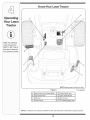
Know Your Lawn Tractor
A
NOTE: Any reference
in this manual to the
RIGHTor LEFT side of
the tractor is observed
from operator's position.
NOTE:Steeringwheelnot shownfor clarity
Figure 8
1-If soequipped
A
SpeedControlLever/ParkingBrake
E
ThrottleControlLever
B
Clutch-BrakePedal
F
IgnitionSwitchModule
C
Shift Lever
G
DeckLift Lever
D
ChokeControl1-
H
PTO(Blade Engage)Lever
NOTE:Anyreferencein this manualto the RIGHTor LEFTside of the tractoris observedfrom operator'sposition.
12
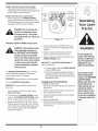
Throttle
Control
Lever
Thethrottlecontrol leveris locatedon the rightside of
thetractor'sdash panel.This levercontrolsthe speed
of the engineand,on somemodels,when pushedall
theway forward,the chokecontrol also.Whenset ina
givenposition,the throttlewill maintaina uniformengine
speed.See Figure9.
FAST--4p
m
|l
IMPORTANT:Whenoperatingthetractorwith the cutting
deck engaged,be certainthat the throttleleverisalways
in the FAST(rabbit)position.
Choke
Control
SLOW __
On some models,movingthe
throttleleverall the way forward
activatestheengine'schoke
_L._
control.On all othermodels,the
chokecontrolcan be foundon
the left side of thedash panel
and isactivatedby pullingthe
knoboutward.Activatingthe
chokecontrolclosesthe choke
plateon the carburetorand aids instartingthe engine.
Referto Starting The Engine on page 16of this manual
for detailedstartinginstructions.
.,-.--.
SLOW
i
_ i
:
iii
ii I ii i_/I
Figure 9
n/Lights
Off
WARNING
lever leave a running
machine unattended,
Ignition Switch
The ignitionswitchisactivatedto startthe engine.Insert
key intothe ignitionswitchand turnclockwiseto the
STARTposition.Releasethe key intothe ON position
onceengine hasfired. See Figure10A.
Start
ignition Switch Module (if Equipped)
Tostart theengine,insertthe key intothe ignitionswitch
and turnclockwiseto the STARTposition.Releasethe
key intothe NORMALMOWINGMODEpositiononce
theengine hasfired.
Tostop the engine,turn theignitionkey counterclockwise
to the OFF position.See FigurelOB.
nto neutral position,
set parking
ake, stop
engine and remove key
to preventunintended
startingl
Normal
Mode
Position
©
WARNING: Never leave a running
machine unattended, Always
disengage PTO, move shift lever
into neutral position, set parking
brake, stop engine and remove
key to prevent unintended
starting,
Always disengage
PTO, move shift lever
Start
Position
IMPORTANT
Prior
tooperating
the
Figure 10
tractor, refer to both
Safety Interlock
Switches
onpag
Deck Lift Lever
IMPORTANT:Priorto operatingthetractor,referto both
Safety Interlock Switches on page 14and Starting
The Engine on page 16 of this manualfordetailed
instructionsregardingthe IgnitionSwitchModuleand
operatingthe tractorin REVERSECAUTIONMODE.
Foundon yourtractor'srightfender,the deck lift leveris
usedto changethe heightof the cuttingdeck. Touse,
movethe leverto the left, then placein the notch best
suitedforyour application.
14and
Engine 0n page i6
ofthismanual
ior
regardingthe Ignition
Switch Module and
operating the tractor in
REVERIE CAUTION
MODEi
13
Speed
FORWARD
HUETRAL
REVERSE_
Figure 11
NOTE:Theparking
brakemustbesetifthe
operatorleavestheseat
withthe enginerunningortheenginewill
automatically
shutoff.
Parking
Brake
Toset the parkingbrake,fully depressthe clutch-brake
pedal.Movethe speedcontrol leverall the way down
and intothe parkingbrakeposition.Releasethe clutchbrakepedalto allowthe parkingbraketo engage.
Toreleasethe parkingbrake,depressthe clutch-brake
pedaland movethe speedcontrol leverout of the
notchesto the desiredposition.Releasethe speed
controlleverand the clutch-brakepedal.
NOTE:Theparkingbrakemustbe set if theoperator
leavesthe seatwith the engine runningor the engine
willautomaticallyshut off.
NOTE:ThePTO(Blade
Engage)
levermustbe
inthe disengaged
(PTO
Clutch-Brake
Pedal
:3FF)position
when
Theclutch-brakepedal is locatedon the left sideof
startingtheengine.
iMPORTANT
Neverforce the shift
lever.Doing so may
result in senous
damage to the tractor's
transmission.
the lawntractor,along the runningboard.Depressthe
clutch-brakepedalpartway downwhenslowingthe
tractorbychangingspeeds(Referto SpeedControl
Lever).Depressthe pedalall theway downto engage
thedisc brakeand bringthe tractorto a completestop.
NOTE:Thepedal mustbe depressedto startthe
engine.Referto SafetyInterlockSwitcheson page 14.
Shift
Control
Lever
Thespeedcontrol lever,locatedon the
left sideof the tractor'sdash console,
allowsyouto regulatetheground speed
of the lawntractor.To use,depressthe
clutch-brakepedal and movethe leveroul
of the parkingbrakenotchand forward
to increasethe tractor'sgroundspeed.
Whena desiredspeedhasbeen reached
releasethe leverintoan appropriate
notchto maintainthat speed.
Toslow the tractor'sgroundspeed,
depresstheclutch-brakepedaland move
the speedcontrol leverrearwardand
releaseit intoa notch.
Lever
The shiftleverislocatedon the left sideof thefender
and hasthree positions,FORWARD,NEUTRALand
REVERSE.The brakepedal mustbe depressedand
thetractor mustnotbe in motionwhenthe movingshift
lever.See Figure11.
NOTE:Lawntractorsvary by modeland
are availablewith eithera 6- or 7-speed
controllever.
PTO (Blade Engage)
Lever
Foundon the tractor'srightfender,the
PTO(bladeengage)leveris usedto
engagepowerto the cuttingdeck or
other(separatelyavailable)attachments.
Tooperate,movethe leverall the way
forward.Movingthe leverall the way
rearwardintothe PTOOFF position
disengagespowerto the cuttingdeck/
attachment.
NOTE:The PTO(bladeengage)lever
mustbe in the disengaged(PTOOFF)
positionwhenstartingthe engine.
Safety
Interlock
z
!2
,t
_3
_4
!
_5
o
"
#
Switches
This tractorisequippedwith a safetyinterlocksystem
for the protectionof the operator.If the interlock
system
shouldever malfunction,do not operatethe tractor.
Contactan authorizedMTDservicedealer.
* Thesafety interlocksystempreventstheengine
fromcrankingor startingunlessthe parkingbrakeis
engaged,andthe PTO(BladeEngage)leveris in the
disengaged(OFF) position.
*
Theenginewill automaticallyshut off if the operator
leavesthe seat beforeengagingthe parkingbrake.
*
Theenginewill automaticallyshut off if the operator
leavesthe tractor'sseat with the PTO(Blade Engage)
leverin the engaged(ON) position,regardlessof
whetherthe parkingbrakeis engaged.
*
Theenginewill automaticallyshut off if the operator
engagesthe PTOwith the parkingbrakeON.
IMPORTANT:Neverforce the shiftlever.Doingso may
result in seriousdamageto the tractor'stransmission.
14
Models without
Reverse Caution Mode
F
• Theenginewill automaticallyshut off if the PTO
(Blade Engage)leveris movedintothe engaged(ON)
positionwith the shiftleverin Reverse.
Models with Reverse Caution
Mode
• With the ignitionkey in the NORMALMOWING
position,the enginewill automaticallyshut off ifthe
PTO(Blade Engage)leveris movedintothe engaged
(ON) positionwith the shiftleverin Reverse.
,_
Reverse
Reverse
Caution Mode
Position
Stop
Position
©
tractor
if theDo
interlock
system
WARNING:
not operate
the
is malfunctioning. This system
was designed for your safety and
protection.
Caution
Reverse
. PushButton
Indicator
Light
_
_ii ii_i i_iii_ii_
i?_i_i_i_ii_ ii__
Start
Position
Figure 12
Mode (if Equipped)
WARNING: Use extreme caution
while operating the tractor in
the REVERSE CAUTION MODE.
Always look down and behind
before and while backing. Do not
operate the tractor when children
or others are around, Stop the
tractor immediately if someone
enters the area.
4. Onceactivated(indicatorlight ON), the tractorcan
be drivenin reversewith thecutting blades(PTO)
engaged.
5. Alwayslookdownand behindbeforeandwhile
backingto make sureno childrenare around.
6. After resumingforwardmotion,returnthe key to the
NORMALMOWINGposition.
IMPORTANT:The REVERSECAUTIONMODEwill
remainactivateduntil:
a. The key is placedin eitherthe NORMALMOWING
positionor STOPposition.
b. The operatorengagesthe parkingbrakebyfully
depressingthe clutch-brakepedaland holdingit
downwhile movingthe speedcontrolleverintothe
PARKBRAKEposition.
The REVERSECAUTIONMODE positionof the key
switchmoduleallows thetractorto be operatedin
reversewith the blades(PTO)engaged.
IMPORTANT:Mowingin reverseis notrecommended.
Tousethe REVERSECAUTIONMODE:
Engaging
IMPORTANT:The operatorMUSTbe seatedinthe
tractorseat.
Toengagethe parkingbrake:
1. Fullydepressthe clutch-brakepedaland hold it down
with yourfoot.
1. Start the engineas instructedon page 16under
Starting The Engine.
2. Movethe speedcontrolleverall the waydownand
intothe parkingbrakeposition.
2. Turnthe key from the NORMALMOWING(Green)
positionto the REVERSECAUTIONMODE(Yellow)
positionof the key switchmodule. See Figure12.
3. Releasethe clutch-brakepedal to allowthe parking
braketo engage.
3. Depressthe REVERSEPUSHBUTTON(Orange,
TriangularButton)at the top, rightcornerof the key
switchmodule.The red indicatorlightat thetop, left
cornerof the keyswitch modulewill be ONwhile
activated.See Figure12.
the Parking
Brake
To releasethe parkingbrake:
1. Depressthe clutch-brakepedaland movethe speed
control leverout of the parkingbrakepositionand into
a desiredspeed.
15
WARNING
Do not operate the
tractor if the interlock
system is malfunctioning. This system was
designed for your
safety and protection.
Use extreme caution
while operating the
tractor in the REVERSE
CAUTION MODE.
Always look down and
behind before and
while backing. Do not
operate the tractor
when children or others are around. Stop
the tractor immediately
f someone enters the
area.
Setting
the Cutting
I G
Height
1. Selectthe heightpositionof the cuttingdeck by
placingthe deck liftleverinany of the six different
cuttingheightnotcheson the rightsideof the fender.
AVOID SERIOUS INJURY OR DEATH
2. Adjustthe deck wheels,if equipped,so that they are
betweenl_-inchand Y2-inchabovethe groundwhen
thetractor is on a smooth,flat surfacesuchas a
driveway.
GO UPAND DOWNSLOPES,NOT ACROSS.
AVOIDSUDDENTURNS.
DO NOT OPERATETHE UNITWHERE IT COULDSLIP OR TIE
YoUr LaWn
IF MACHINE STOPSGOINGUPHILL,STOP BLADE(S) AND
BACK DOWNHILLSLOWLY.
i
WARNING: Keep hands and feet
away from the discharge opening of the cutting deck.
Tractor
DO NOT MOWWHEN CHILDRENOROTHERS AREAROUND.
NEVER CARRYCHILDREN,EVENWITH BLADESOFR
LOOK DOWNAND BEHIND BEFOREAND WHILE BACKING.
NOTE:On modelsso equipped,thedeck wheelsare an
anti-scalpfeatureof thedeck and are notdesignedto
supportthe weightof the cuttingdeck.
KEEP SAFETY DEVICES(GUARDS,SHIELDS,AND SWITCHES)
IN PLACEAND WORKING.
REMOVEOBJECTSTHAT COULDBE THROWNBYTHE
Referto Levelingthe Deckon page 20 of this manual
for moredetailedinstructions
regardingvariousdeck
adjustments.
WARNING
BLADE(S).
KNOW LOCATIONAND FUNCTIONOF ALL CONTROLS.
BE SURE BLADE(S) AND ENGINEARE STOPPEDBEFORE
Starting
PLACING HANDSOR FEETNEAR BLADE(S).
the Engine
BEFORE LEAVINGOPERATOR'SPOSITION,DISENGAGE
BLADE(S), PLACETHE SHIFT LEVERIN NEUTRAL,ENGAGE
Keep hands and feet
away from the discharge opening of the
cutting deck.
Do not operate the
tractor if the interlock
system is malfunctioning.This system was
designed for your
safety and protection.
,,__
BRAKE LOCK, SHUT ENGINEOFF AND REMOVEKEY.
tractor
if theDo
interlock
system
WARNING"
not operate
theis
malfunctioning. This system was
designed for your safety and
protection.
READ OPERATOR'S
Stopping
NOTE:Referto the TRACTORSET-UPon page8 of
this manualfor Gasolineand Oil fill-upinstructions.
__
1. Insertthe tractorkey intothe ignitionswitch.
2. Placethe PTO(Blade Engage)leverin the disengaged(OFF) position.
3. Engagethetractor'sparkingbrake.
MANUAL
the Engine
object, stop the engine, disconARNING: if you strike a foreign
nect the spark plug wire(s) and
ground against the engine. Thoroughly inspectthe machine for
any damage. Repair the damage
before restarting and operating
4. Activatethe chokecontrol.
if you strike a foreign
object, stop the
engine, disconnect
the spark plug wire(s)
and ground against
the engine. Thoroughly
inspectthe machine
for any damage. Repair
the damage before
restarting and operating.
5. Turnthe ignitionkey clockwiseto the STARTposition. Afterthe engine starts,releasethe key.It will
returnto the ONposition.
1. If the bladesare engaged,placethe PTO(Blade
Engage)leverin the disengaged(OFF) position.
2. Turnthe ignitionkey counterclockwiseto the STOP
position.
IMPORTANT:DoNOThold the key in the START
positionfor longerthanten secondsat a time. Doingso
maycause damageto yourengine'selectricstarter.
3. Removethe keyfrom the ignitionswitchto prevent
unintendedstarting.
6. Afterthe engine starts,deactivatethe chokecontrol
and placethe throttlecontrol in the FASTposition.
NOTE:Do NOTleavethe chokecontrolon while operating the tractor.Doingsowill result in a "rich" fuelmixture
and causethe engineto run poorly.
16
NOTE:Whenoperatingthe unit initially,there willbe little
differencebetweenthe highesttwo speedsuntilafter the
beltshaveseatedthemselvesinto the pulleysduringthe
break-inperiod.
Driving The Tractor
WARNING: Avoid sudden starts,
e×-cessive speed and sudden
stops.
_
WARNING: Do not leave the seat
of the tractor without first placingthe PTO (Blade Engage) lever
in the disengaged (OFF) position, depressing the brake pedal
and engaging the parking brake.
if leaving the tractor unattended,
also turn the ignition key off and
remove the key.
operator's position for any
ARNING: Before leaving the
reason, disengage the blades,
place the shift lever in neutral,
engage the parking brake, shut
engine off and remove the key.
IMPORTANT:Whenstoppingthe tractorfor anyreason
whileon a grass surface,always:
1. Placethe shift leverin neutral,
2. Engagethe parkingbrake,
3. Shutengineoff and removethe key.
1. Depressthe brakepedalto releasetheparkingbrake
and let the pedalup.
Doingsowill minimizethe possibilityof havingyourlawn
"browned"by hot exhaustfromyourtractor's running
engine.
If unit stalls with speedcontrolin high speed,or if unit
willnot operatewith speedcontrolleverin a lowspeed
position,proceedas follows:
1. Placeshiftleverin NEUTRAL.
2. Movethe throttleleverintothe FAST(rabbit)position.
2. Restartengine.
3. Placethe shiftleverin eitherthe FORWARDor
3. Placespeedcontrol leverin highestspeedposition.
Always look down and behind
before and while backing up to
avoid a back-over accident.
REVERSEposition.
Avoid sudden starts,
ex-cessive speed and
sudden stops.
4. Releaseclutch-brakepedalfully.
5. Depressclutch-brakepedal.
IMPORTANT:DoNOTuse the shift leverto changethe
directionof travelwhenthe tractoris in motion.Always
usethe brakepedalto bringthe tractorto a complete
stop beforeshifting.
6. Placespeedcontrol leverin desiredposition.
7. Placeshiftleverin eitherFORWARDor REVERSE,
and follownormaloperatingprocedures.
4. Releasethe parkingbrakebydepressingthe clutchbrakepedaland positioningthe speedcontrolleverin
desiredposition.
IMPORTANT:First-timeoperatorsshouldusespeed
positions1 or 2. Becomecompletelyfamiliarwith the
tractor'soperationand controlsbeforeoperatingthe
tractorinhigher speedpositions.
.
WARNING
Releaseclutch-brakepedal slowlyto putunit into
motion.
6. The lawntractoris broughtto a stop bydepressing
theclutch-brakepedal.
Do not leave the seat
of the tractor without
first placingthe PTO
(Blade Engage)lever in
the disengaged (OFF)
position, depressing
the brake pedal and
engaging the parking
brake, if leaving the
tractor unattended,
also turn the ignition
key off and remove the
key.
Always look down
and behind before
and while backing up
to avoid a back-over
_ccident.
17
Driving On Slopes
Using the Deck Lift Lever
Referto the SLOPEGAUGEon page3 to help determineslopeswhereyou mayoperatethe tractorsafely.
Toraisethe cuttingdeck,movethe deck lift leverto the
left,thenplaceit inthe notch best suitedfor yourapplication. Referto SettingThe CuttingHeightearlierin this
section.
,_
inclineswith a slope in excess
WARNING:
Do(anot
mow
on
of 15 degrees
rise
of approximately 2-1/2 feet every 10feet).
The tractor could overturn and
Mowing
WARNING: To help avoid blade
contact or a thrown object injury,
keep bystanders, helpers, children
and pets at least 75 feet from the
machine while it is in operation.
Stop machine if anyone enters the
area.
cause serious injury.
• Mow up and downslopes,NEVERacross.
• Exerciseextremecautionwhenchangingdirection
on slopes.
• Watchfor holes, ruts,bumps,rocks,or otherhidden
objects.Uneventerraincouldoverturnthe machine.
Tallgrasscan hide obstacles.
WARNING
Do not mow on inclines
with a slope in excess
of 15 degrees (a rise
of approximately 2-1/2
feet every 10 feet). The
tractor could overturn
and cause serious
injury.
To help avoid blade
;ontact or a thrown
object injury, keep
bystanders, helpers,
;hildren and pets at
least 75 feet from the
machine while it is in
operation. Stop ma;hine if anyoneenters
the area.
• Avoidturns whendrivingon a slope. If a turn must
be made,turn downthe slope.Turningup a slope
greatlyincreasesthechanceof a roll over.
Thefollowinginformation
will be helpfulwhenusingthe
cuttingdeckwith yourtractor:
WARNING: Plan your mowing
pattern to avoid discharge of
materials toward roads, sidewalks,
bystanders and the like. Also,
avoid discharging material against
a wall or obstruction which may
cause discharged material to
ricochet back toward the operator.
• Avoidstoppingwhendrivingup a slope. If it is
necessaryto stop whiledrivingup a slope, startup
smoothlyand carefullyto reducethe possibilityof
flippingthe tractoroverbackward.
Engaging
the Blades
Engagingthe PTO(Blade Engage)transferspowerto
thecutting deckor other(separatelyavailable)attachments.Toengagethe blades,proceedas follows:
1. Movethe throttlecontrolleverto the FAST(rabbit)
position.
2. Graspthe PTO(Blade Engage)leverand pivotit all
theway forwardinto theengaged(ON) position.
•
Do not mowat high groundspeed,especiallyifa
mulchkit or grass collectoris installed.
•
For best resultsit is recommendedthat the firsttwo
lapsbe cut with the dischargethrowntowardsthe
center.Afterthe first two laps, reversethedirectionto
throwthe dischargeto the outsidefor the balanceof
cutting.This will givea betterappearanceto the lawn.
3. Keepthe throttleleverinthe FAST(rabbit)position
for the mostefficientuseof the cuttingdeck or other
(separatelyavailable)attachments
•
Do notcut thegrass too short.Shortgrass invites
weedgrowthand yellowsquicklyindry weather.
•
Mowingshouldalwaysbe done with theengineat full
throttle.
iMPORTANT:Models with Reverse Caution Mode:
Theenginewill automaticallyshut off ifthe PTOis
engagedwith the shift leverin positionfor reversetravel
with the ignitionkeyin the NORMALMOWINGposition.
Models withoutReverseCautionMode:
Underheavierconditionsit may be necessaryto go
back overthecut areaa secondtime to get a clean
cut.
The PTO(BladeEngage)levermust be in thedisengaged(OFF) positionwhen startingthe engine,when
travelingin reverse,and if the operatorleavesthe seat.
Referto SafetyinterlockSwitcheson page 14.
18
• Do NOTattemptto mow heavybrushand weedsand
extremelytall grass.Yourtractoris designedto mow
_
_
" -/A
awns,
NOT
dear
brush
I
//I
• Keepthe bladessharpand replacethe bladeswhen
worn. Referto Cutting Blades on page 25 of this
manualfor properblade sharpeninginstructions.
"i.:
/
....
",,,
'
[J
Operating
Mulching
(If Equipped)
Selectmodelscome equippedwith a mulch kit which
incorporatesspecialblades,alreadystandardon the
tractor,in a processof recirculatinggrass clippings
repeatedlybeneaththe cuttingdeck.Theultra-fine
clippingsarethen forcedback intothe lawnwherethey
act as a naturalfertilizer.
Observethe followingpointsfor the best resultswhen
mulching:
• Neverattemptto mulchif the lawnis damp.Wet grass
tendsto stickto theundersideof the cuttingdeck
preventingpropermulchingof the clippings.
• Do NOTattemptto mulch morethan 1/3the total
heightof the grassor approximately1-1/2inches.
Doingso willcause theclippingsto clump up beneath
thedeck and notbe mulchedeffectively.
• Maintaina slow groundspeedto allowthe grass
clippingsmoretime to effectivelybe mulched.
Figure 13
WARNING
Planyour mowing pattern to avoid discharge
of materials toward
• Alwayspositionthe throttlecontrol leverin the FAST
(rabbit)positionand allowit to remaintherewhile
mowing.Failingto keepthe engineat full throttle
placesstrainon the tractor'sengineand doesnot
allowthe bladesto properlymulchgrass.
roads, sidewalks, bystanders and the like.
Also, avoid discharging
_aterial against a wall
_r obstruction which
NOTE:It is not necessaryto removethe dischargechute
to operatethe mowerwith the mulchkit installed.
may cause discharged
aterial to ricochet
back toward the
operator.
Tooperatethe cuttingdeck withoutmulching,simply
removethe mulch plug byunthreadingthe plasticwing
nutwhich fastensit to the cuttingdeck.This will allowthe
clippingsto dischargeout the side.See Figure13.
Headlights
• On some models,the lampsare ON wheneverthe
tractor'sengine isrunning.On othermodels,the
lampsare ON wheneverthe ignitionkey is movedout
of the STOPposition.
• On all models,the lampsturn OFFwhenthe ignition
key ismovedto the STOPposition.
19
1. With the tractorparkedon a firm,levelsurface,place
the deck lift leverin the top notch(highestposition)
and rotatethe blade nearestthe dischargechute so
that itis parallelwith the tractor.
2. Measurethe distancefrom the front ofthe bladetip to
the groundand the rearof the blade tip to the ground.
Thefirst measurementtakenshouldbe between
1/4"and 3/8" less than thesecond measurement.
Determinethe approximatedistancenecessaryfor
properadjustmentand proceed,if necessary,to the
next step.
3. Locatethejam nut and lock nut on the front sideof the
stabilizerbracket.See Figure14.After looseningthe
jam nut:
Tightenthe lock nutto raisethefront of the deck;
Loosenthe lock nut to lowerthefront of the deck.
WARNING
4. Retightenthe jam nut loosenedearlierwhen proper
adjustmentis achieved.
Figure 14
Side to Side
Neverattemptto
If the cuttingdeck appearsto be mowingunevenly,a side
to side adjustmentcan be performed.Adjustif necessary
as follows:
make any adjustments while the
1. With the tractorparkedon a firm,levelsurface,place
the deck lift leverin the top notch(highestposition)
and rotateboth bladesso that they are perpendicular
with the tractor.
engine is running,
except where specii manual.
fied in the operator's
2. Measurethe distancefrom the outsideof the left blade
tip to the groundand the distancefrom theoutside of
the rightblade tip to theground.Bothmeasurements
takenshouldbe equal. If they'renot, proceedto the
next step.
i Never attempt to
iadjust the brakes
_wh ie the engine
3. Loosen,butdo NOT remove,the hexcap screwon
the left deck hangerbracket.See Figure15.
i is running. Always
idisengage PTO, move
::shift lever into neutral
position, stop engine
and remove key to
iprevent unintended
istarting.
4. Balancethe deck by usinga wrenchto turn the
adjustmentgear (foundimmediatelybehindthe hex
cap screwjust loosened)clockwise/upor counterclockwise/down.Thedeck is properlybalancedwhen
bothblade tip measurementstakenearlierare equal.
Figure 15
,_
Leveling
5. Retightenthe hex capscrewon the left deck hanger
bracketwhenproperadjustmentis achieved.
make
any adjustments
while
WARNING:
Never attempt
to
the engine is running, except
where specified in the operator's
manual.
Parking Brake Adjustment
the Deck
_
NOTE:Checkthe tractor'stire pressurebeforeperforming anydeck levelingadjustments.Referto Tires on
page24 for information
regardingtire pressure.
Front To Rear
Thefront of the cuttingdeck is supportedbya stabilizer
bar that canadjustedto levelthe deck from frontto rear.
Thefront of the deck shouldbe between1/4-inchand
3/8-inch lowerthanthe rear of the deck.Adjustif
necessaryas follows:
just
the brakes
while
the engine
ARNING"
Never
attempt
to ad- is
running. Always disengage PTO,
move shift lever into neutral position, stop engine and remove key
to prevent unintended starting.
If the tractordoes notcome to a completestopwhenthe
brakepedalis completelydepressed,or if the tractor's
rear wheelscan roll with the parkingbrakeapplied,the
2O
brakeis in need of adjustment.Thebrakedisc can be
foundon the rightsideof thetransmissionin the rear of
the tractor.Adjustif necessaryas follows:
1. Lookingat thetransmissionfrom the right sideof the
tractor,locatethe compressionspringand brakedisc.
See Figure16.
Adjusting
urLawn
2. Loosen,but do NOTremove,the hex nutfoundon the
rightsideof the brakeassembly.See Figure16.
3. Usinga feelergauge,set the gap betweenthe brake
disc and the brakepuck at .011".
4. Re-tightenthe hexnut loosenedearlier.
Seat Adjustment
_
machine,
make
sure
the seat this
is
ARNING:
Before
operating
engaged in the seat stop, stand
behind the machine and pull back
on seat until fully engaged into
stop.
Set gap
Hex Nut
WARNING
Figure 16
Before operating this
machine, make sure
the seat is engaged in
the seat stop, stand
behind the machine
Standard Seat
Toadjust the positionof the seat,loosenthe two hex
screwson the bottomof the seat.Slide the seatforward
or backwardas desired.Retightenthe two screws.See
Figure17.
and pull back on seat
until fully engaged into
stop.
Knob Adjustment Seat (if so equipped)
Toadjust the positionof the seaton modelsso equipped,
loosenthe two knobson the bottomof theseat. See
Figure18.Slidethe seat forwardor backwardas desired.
Retightenthe two knobs.
Quick Adjust Seat (if so equipped)
Toadjust the positionof the seaton modelsequipped
with a seat adjustmentlever,movethe seatadjustment
lever(locatedunder theseat) to the left and slidethe seat
forwardor rearward.See Figure19.Makesureseat is
locked intopositionbeforeoperatingthe tractor.
Figure 17
.....J
\
Figure 19
Figure 18
21
Performthe abovestepsin the oppositeorder afteroil has
finisheddraining.
5. Refillthe enginewith newmotoroil as instructedin the
EngineOperator/OwnerManualpackedwith your unit.
IMPORTANT:Referto the EngineOperator/Owner
Manualpackedwith yourunit for informationregardingthe
quantityand properweight of motoroil.
Air Cleaner
Servicethe pre-cleaner,if soequipped,and cartridge/air
cleanerelementas instructedin the EngineOperator/
OwnerManualpackedwith your unit.
Spark Plug(s)
Thespark plug(s)shouldbe cleanedand thegap reset
oncea season.Sparkplug replacementis recommended
at the startof each mowingseason.Referto the Engine
Operator/OwnerManualfor correctplug type and gap
specifications.
Figure 20
WARNING
,_
any maintenance or
repairs, disengage
PTO, move shift lever
intoneutral position,
set parkingbrake, stop
engine and remove key
o preventu nintended
_tarting!
Before lubricatingi
repairing, or inspect,
ing, always disengage
PTOImove shift lever
into neutral position,
set parking brake, stop
engine
and
remove
key
to prevent unintended
startingl
any
maintenance
repairs,
WARNING:
Beforeorperforming
disengage PTO, move shift lever
into neutral position, set parking
brake, stop engine and remove
key to prevent unintended
starting.
Lubrication
WARNING: Before lubricating,
repairing, or inspecting, always
disengage PTO, move shift lever
into neutral position, set parking
brake, stop engine and remove
key to prevent unintended starting.
Engine
Refer to the Engine Operator/Owner Manualfor
engine maintenance instructions.
Checkengine oil levelbeforeeachuseas instructed
inthe EngineOperator/OwnerManualpackedwith your
unit. Follow the instructionscarefully.
Changing
Engine
Lubricatethe enginewith motoroil as instructedin the
EngineOwnerManualpackedwith yourunit.
Engine Oil
Pivot Points & Linkage
Lubricateall the pivotpoints on the drivesystem,parking
brakeand lift linkageat least oncea seasonwith lightoil.
NOTE:Dependingon the engine modelfoundon your
tractor,it may be necessaryto removethe tractor'sside
panelin order to replacethe oil filter (if so equipped).
Rear Wheels
The rearwheelsshouldbe removedfrom the axles once
a season.Lubricatethe axles and the rimswell with an
Fordrainingoil from the engine'scrankcaseof select
modeltractors,a plasticoil drain sleeveis packedwith
this Operator'sManual.Todrain the oil, proceedas
follows:
1. Unscrewthe oil fill capand removethe dipstickfrom
theoil fill tube.
all-purposegreasebeforere-installingthem.
Front Axles
Eachend of the tractor'sfront pivot bar may be equipped
with a greasefitting. Lubricatewith a greasegun after
every25 hoursof tractoroperation.
2. Snapthe small end of oil drain sleeveontothe oil
sump.See Figure20.
Cleaning
3. Removedrain plug and drain oil intoa suitable
containerwith a capacityof no less than64 oz.
NOTE:Dependingon
the engine model found
Onyour tractorl itmay
be necessary to remove
the tractor!s side panel
in OrdertO replace the
oil filter (if so equipped):
4. Servicethe oil filter (if soequipped)as instructedin
the separateEngineOperator/OwnerManualpacked
with yourunit.
the Engine
And Deck
Anyfuel or oil spilledon the machineshouldbe wiped
off promptly.Do NOTallowdebristo accumulatearound
the coolingfins of the engineor on any otherpart of the
machine.
IMPORTANT:The useof a pressurewasherto cleanyour
tractoris NOT recommended.It maycause damageto
electricalcomponents,spindles,pulleys,bearingsor the
engine.
22
Deck Wash System TM
A hexplug can be foundon yourtractor'sdeck surface.
See Figure21.
This plug canbe replacedwith a waterport to be usedas
part of a separately-available
deck wash system.
Use the DeckWashSystemTM to rinsegrassclippings
fromthe deck'sundersideand preventthe buildupof
corrosivechemicals.
NOTE:Referto page 28 for informationregardingthis
and otherseparately-available
attachments& accessoriesfor yourtractor.
Cutting
Deck Removal
NOTE:Modelsequippedwith a 38-inchdeck haveone
deck idler pulley.Modelsequippedwith a 42-inchdeck
havetwo deck idler pulleys.
Figure 21
To removethecuttingdeck, proceedas follows:
1. Placethe PTO(Blade Engage)leverin the disengaged(OFF) positionandengagethe parkingbrake.
tOTE: Models
2. Lowerthe deck by movingthedeck lift leverinto the
bottomnotchon the rightfender.
equipped with a 38-inch
deck have one deck
3. Removethe beltfrom aroundthetractor'sengine
pulleyand idler pulley(s).Referto Changingthe Deck
Belton page26 for detailedinstructions.
idler pulley. Models
eau_ppedwith a 42-inch
deck have two deck
4. Lookingat the cuttingdeck from theleft sideof the
tractor,locatethe hair pin clip that securesthe deck
supportrod on the rear left sideof the deck. See
Figure22.
idler pulleys.
5. Removethe hair pin clipthat securesthedeck
supportrod, and carefullyremovethe deck support
fromthe deck lift arm.
6. Repeattheabovestepson thetractor'srightside.
\
7. Movethe deck lift leverintothe top notchon the right
fenderto raisethe deck lift arms up and out of the
way.
Figure 22
8. Carefullyremovethe PTOcablefrom the rearof
the cuttingdeck by removingthe hair pinclip which
securesit. Removethe springfrom the deck idler
bracket.See Figure23.
9. Gentlyslidethe cuttingdeck towardthe frontof the
tractorallowingthe hookson the deck to release
themselvesfrom thedeck stabilizerrod.
10.Gentlyslidethe cuttingdeck (from the rightside)out
from underneaththe tractor.
Figure 23
23
Tires
,_
Jump Starting
maximum inflation
pressure
WARNING:
Never exceed
the
shown on the sidewall of tire.
,_
The recommendedoperatingtire pressureis:
• Approximately10 psifor the rear tires
IMPORTANT:Neverjump yourtractor'sdead batterywith
the batteryof a runningvehicle.
• Approximately14psi for the fronttires
IMPORTANT:Referto the tire sidewallforexacttire
1. Connectend of one jumpercableto the positive
terminalof the good battery,thenthe otherend to the
positiveterminalof the dead battery.
manufacturer'srecommendedor maximumpsi. Do not
overinflate.Uneventirepressurecouldcausethe cutting
deck to mow unevenly.
2. Connectthe otherjumpercable to the negative
terminalof the good battery,thento the frame of the
unit with the dead battery.
Battery
WARNING
Never exceed the
maximum inflation
pressure shown on the
sidewall of the tire.
Batteries give off an
explosive gas while
charging. Charge bat=
tery in a well ventilated
area and keep away
from an open flame
or pilot light as on a
water heater, space
heater, furnace, clothes
dryer or other gas
appliances.
Always use a fuse with
the same amperage
capacity for replace=
merit.
WARNING:When removing or
installing the battery, follow
these instructionsto prevent the
screwdriver from shorting against
the frame.
The batteryis sealedand is maintenance-free.Acid
levelscannotbe checked.
• Alwayskeepthe batterycablesand terminalsclean
and freeof corrosivebuild-up.
_
• Aftercleaningthe batteryand terminals,apply a light
coat of petroleumjellyor greaseto bothterminals.
procedure
cause
sparking,
WARNING"could
Failure
to use
this
and the gas in either battery could
explode.
• Alwayskeepthe rubberboot positionedoverthe
positiveterminalto preventshorting.
IMPORTANT:Ifremovingthe batteryfor anyreason,
disconnectthe NEGATIVE(Black)wire fromit'sterminal
first, followedby the POSITIVE(Red)wire. When
re-installingthe battery,alwaysconnectthe POSITIVE
(Red)wire itsterminalfirst, followedby the NEGATIVE
(Black)wire. Be certain that thewires are connectedto
thecorrectterminals;reversingthemcouldchangethe
polarityand result indamageto your engine'salternating system.
Charging
If thetractorhas not beenput into usefor an extended
periodof time,chargethe batterywith an automotivetype 12-voltchargerfora minimumof one hour at six
amps.
WARNING: Batteries give off an
explosive gas while charging.
Charge battery in a well ventilated area and keep away from
an open flame or pilot light as
on a water heater, space heater,
furnace, clothes dryer or other
gas appliances.
Cleaning
Cleanthe batteryby removingit fromthe tractorand
washingwith a bakingsodaand water solution.If necessary,scrapethe batteryterminalswith a wire brushto
removedeposits.Coat terminalsand exposedwiringwith
greaseor petroleumjelly to preventcorrosion.
Battery Failures
Somecommoncausesfor batteryfailureare:
• incorrectinitialactivation • undercharging
• overcharging
• corrodedconnections
• freezing
These failures are NOTcovered by your tractor's
warranty.
Fuse
One 20 AMPfuse is installedin yourtractor'swiring harness to protectthe tractor'selectricalsystemfrom damage
causedby excessiveamperage.
If the electricalsystemdoesnot function,or yourtractor's
enginewill notcrank,first checkto be certainthat the fuse
has notblown. It can be foundunder thehood mounted
behindthe dashpanelon the rightside.
,_
24
the
same amperage
capacity
WARNING:
Always use
a fusefor
with
replacement.
S
Cutting
Blades
f
WARNING: Be sure to shut
the engine off, remove ignition
key, disconnect the spark plug
wire(s) and ground against the
engine to prevent unintended
starting before removing the cutring blade(s) for sharpening or
replacement. Protect your hands
by using heavy gloves or a rag to
grasp the cutting blade.
WARNING: Periodically inspect
the blade spindles for cracks or
damage, especially if you strike a
foreign object. Replace immediately if damaged.
Figure 24
WARNING
The bladesmay be removedas follows.
1. Removethe deck from beneaththe tractor,(referto
CuttingDeckRemovalon page23) thengently flip
thedeck overto expose its underside.
2. Placea blockof wood betweenthe centerdeck housing baffle and the cuttingbladeto act as a stabilizer,
See Figure24,
3, Use a 15/16"wrenchto removethe hexflangenut
that securesthe bladeto the spindleassembly.See
Figure24,
4. Toproperlysharpenthe cuttingblades,removeequal
amountsof metalfrom bothends of the bladesalong
thecutting edges,parallelto the trailingedge,at a
250to 300angle,
1-5/8 inch
Figure 25
IMPORTANT:If the cuttingedgeof the blade hasalready
been sharpenedto within 1 5/8" from theedge,or if any
metal separationis present,replacethe bladeswith new
ones, See Figure25,
It isimportantthat eachcuttingblade edge be ground
equallyto maintainproperblade balance.
A poorlybalancedbladewill causeexcessive
vibrationand maycausedamageto thetractorand
result in personalinjury,The bladecan be testedby
balancingit on a roundshaftscrewdriver.Grind metal
fromthe heavysideuntil it balancesevenly.
25
Whenreplacingthe blade,be sureto installthe blade
with theside of the blade marked"Bottom" (or with
a part numberstampedin it) facing the groundwhen
themoweris in the operatingposition.
IMPORTANT:Use a torquewrenchto tightenthe blade
spindlehexflange nutto between70 foot-poundsand 90
foot-pounds.
Be sure to shut the
engine off, remove
ignition key, disconnect the spark plug
wire(s) and ground
against the engine to
prevent unintended
starting before removing the cutting blade(s)
for sharpening or
replacement. Protect
your hands by using
heavy gloves or a rag
to grasp the cutting
blacle,
Periodically inspect
the blade spindles for
cracks or damage,
especially if you strike
a foreign object.
Replace immediately if
damaged.
Tochangeor replacethe deck belt and PTObelton your
tractor,proceedasfollows:
1. Lowerthe deck by movingthe decklift leverinto the
bottomnotchon the rightfender.
2. Removethebelt guardsby removingthe self-tapping
screwsthat fastenthem to the deck.
i ioto°i°g
3. Removethebelt keeperrod fromaroundthe engine
pulley.
4. Inserta 3/8"-driveratchetwrench (set to loosen)into
the squarehole foundin the idler bracketon the left
sideof the deck'ssurface.See Figure26.
5. Graspthe ratchet'shandleand pivot it towardthe front
of the tractorto relievetensionon the belt.
6. With belttension relieved,carefullyremovethe belt
from around the left-hand spindlepulley.
Figure 26
Changing
WARNING
_
Be sure to shutthe
engine off, remove ignition key, disconnect
the spark plug wire(s)
and ground against
the engine to prevent
unintended starting
before removingthe
belt(s).
Avoid the possibility of
a pinching injury.Do
not place your fingers
on the idler spring or
between the belt and a
pulley while removing
the belt.
IMPORTANT:Carefullyallowthe ratchetto pivotrearward
beforeremovingit from the squarehole.
the Deck Belt & PTO Belt
the
engine off,
ignition
WARNING"
Be remove
sure to shut
key,disconnect the spark plug
wire(s) and ground against the
engine to prevent unintended
starting before removingthe
belt(s).
_
of
a pinching
injury.
not place
WARNING"
Avoid
theDo
possibility
your fingers on the idler spring
or between the belt and a pulley
while removing the belt.
7. Removethedeck belt fromaroundall pulleys,including
the deck idler pulley.
All beltson yourtractorare subjectto wearand should
be replacedif anysigns of wearare present.
8. Routethe newbelts as shownin and Figure27 and 28.
9. Remountthe beltguardsremovedearlier.
IMPORTANT:TheV-beltsfoundon yourtractorare
speciallydesignedto engageand disengagesafely.A
substitute(non-OEM)V-beltcan be dangerousby not
disengagingcompletely.Fora properworkingmachine,
usefactory approvedbelts.
Changing
Belts
the Transmission
Drive
NOTE:Severalcomponentsmustbe removedand
specialtools (i.e. air/impactwrench)in order to change
the tractor'sdrivebelts. Seean authorizedMTDService
Dealerto haveyour drivebelts replacedor phone
CustomerSupportas instructedon page 2 for information
on orderinga Service Manual.
26
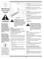
42-Inch Deck
_
EnginePu_
IdlerBracket
Maintaining
Your Lawn
Tractor
©
Deck Idler Pulleys
..
j
Figure 26
f
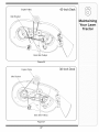
38-Inch Deck_
Engine Pulley
Idler Bracket
©
Deck Idler Pulleys
Figure 27
27
Cleanand lubricatethe tractoras instructed
in Section
Followthe instructions
in the Service, Storage &
Specifications sectionof the EngineOperator/Owner
Manualfor properenginecare priorto storingyourtractor.
6: MAiNTAiNiNGYOUR LAWNTRACTORon page 19
of this manualbeforestoringfor an extendedperiod.
WARNING: Never store the
_
anARNING"
approvedDrain
containeroutdoors,
fuel only into
away from an open flame. Allow
engine to cool. Extinguish
cigarettes, cigars, pipes, and
other sources of ignition prior to
draining fuel.
__
Attachments
achine
or fuel
container
indoors
where
there
is an
open flame,
spark or pilot light such as on
water heater, furnace, clothes
dryer or other gas appliance.
& Accessories
Thefollowingattachmentsand accessoriesare compatiblefor ModelSeries700 LawnTractors.See the retailer
from whichyou purchasedyourtractor,an authorizedMTDServiceDealeror phone(800) 800-7310for information
regardingpriceand availability.
NOTE:ModelSeries700 LawnTractorsare NOTdesignedfor usewith any type of ground-engagingattachments
(e.g.tiller or plow). Useof this type of equipmentWILL voidthe tractor'swarranty.
MODEL
WARNING
Drain fuel only into an
approvedcontainer
outdoors,away from
an open flame. Allow engine to cool
Extinguishcigarettes,
cigars, pipes, and
other sources of ignition prior to draining
fuel.
I
DESCRiPTiON
0EM-190-032 42-inchTwo-stageSnowThrower
OEM-190416 .... 38/42-inchDeckMulch Kit
0EM-190-180
0EM-190-183'
0EM-190-218
OEM-190-607'
Twin BaggerGrassCollector(for 38/42-inchDecks)
DeckWheelKit
RearWheelWeightKit
DeluxeTract0rsUnshade
OEM-190-658
Tire Chains,20 x 8 Tires
OEM-190:672
Grille GUard(mountson front oftractor)
OEM-190-833
42-inchFrontDozerBlade
490_900-0025 "Deck Wash Kit
* Notcompatiblewith tractorsequippedwith a Grass Collector
Never store the machine or fuel container
indoors where there is
an open flame, spark
or pilot lightsuch
as on water heater,
furnace, clothes dryer
or other gas appliance.
28
NOTE:i. eOTH
MODES,
WHEN
OP_e_TO_
LeavesSEAT,
e_GINeWlL_
STOP
_NLES_
_R_I_QeP_KE
ISSETANDe_ossme _ISEN_ED.
IF
UNIT
WILL
STALLS
W]TH
NOT OPERATE
POSITION,
PROCEED
SPEED
CONTROL
WITH
SPEED
_S
FOLLOWS:
IN HIGH
CONTROL
SPEED,
LEVER
OR IF
IN _ LOW
UNIT
SPEED
WARNING
This symbol points
out importantsafety
instructionswhich, if
not followed,could
endangerthe personal
safety and/or property
of yourselfand others.
Read and follow all
instructionsin this
manual beforeattemptingto operate
this machine. Failure
to comply with these
instructionsmay result
in personalinjury.When
you see this symbol.
HEED ITS WARNING!
Your Responsibility
Restrict the use
ASSEMBLE CHUTE DEFLECTOR TO THIS UNIT BEFOREOPERATING.
of this power machine
to persons who read,
understand
and follow the warnings
and instructions
in this manual
and onthe machine.
29
Pro bl e m
Ca use
Enginefails to start I
Remedy
1 PTOengaged.
1 PlacePTOknob(or lever)in
2. Sparkplugw re(s)disconnected.
3 Fueltank empy
t or stalefuel.
4 Chokenot actvated
2. Connectwire(s) to spark plug(s).
3• F tankwth c ean fresh gaso ne
4. Pullout the CHOKEcontrol (if so
I
disengaged(OFF)position.
I
I
Trou e
Shootin
I
"
'
equipped)or placethe throttle
I
control inCHOKEposition.
I
5. Faultysparkplug,
5. Clean,adjust gap,or replace
I
6. Blockedfuel line.
6. Cleanfuel line or replacefuelfilter,
I
I
7. Engineflooded,
I
I
position.
I
I
I
8 Parkng brakenotengaged
9. Throttlecontro levernotin correct
startingposition.
Engineruns erratic
I
,
_
1, Unit runningwith CHOKEapplied,
For repairs beyond
the minor adjustments listed here,
contact an authorized
service dealer.
2. Connectandtighten spark
plugwire(s).
3. Cleanfuel line;fill tank with clean,
fresh (less than30 daysold)
gasoline.Replacefuel filter,ifso
equipped.
3, Blockedfuelline or stale fuel,
J
8. Engageparkingbrake.
9. Placethrottleleverto FAST
position.
1, PushCHOKEcontrol(if so
equipped)in,or movethe throttle
controlout of the CHOKEposition.
2, Sparkplug wire(s) loose,
_
if so equipped.
7 Crank enginewith thrott e n FAST
4, Ventingas cap plugged,
4. Clearvent or replaceif damaged.
5, Wateror dirt infuel system,
5. Drainfuel tank. Refillwith
fresh fuel.
6. Dirty air cleaner.
6. Replaceair cleanercartridge/elementor cleanpre-cleaner,if so
equipped.
_
=__
30
i
Problem
Engineoverheats
Cause
!i
Engine Oi!levellow.
21 Air flow restricted.
2 c eangrass clippingsand debiis
fromaroundthe engines €00!ing
fins and blowerhousing.
.....
Enginehesitates at
high RPM
Idles poorly
1. Sparkplug(s)gap tooclose,
Mower will not
ohgrass (If
Equipped)
1 ' Sparkpug(s)foued fautyorgap
too wide_
1' Repacesparkpug(s)Setpug(s)
t
gap:
1. Cuttingblade looseor unbalanced.
Replaceair cleanercaitr dgdele:
mentor cleanpre:cleaner if So
equipped.
1. Tightenbladeand spindle. Balanc_
2. Damagedor bentcuttingblade.
2. Replaceblade.
11 Enginespeedtoo iowl
1; P!acethrott!e €ontrolin FAST
blade.
wet grass
(rabbit)p0siti°n.
3. Excessivelyhigh grassl
Uneven cut
1, Removesparkplug(s)and reset
the gap,
2 Dirtyair €eaner
Excessive
Vibration
Remedy
!i Fi!!Ciankcasewith pr0pero!!,
2. Donot m0wwhengrass s wet
wat unt aterto cut
,,,
_.
Mowonce a! a nign cuttingneight,
then mow againat desiredheight
or makea narrowerCuttingpath,
Duiiblade
1. Decknotbalancedproperly.
2. Dullblade,
&sharpen or repiacebiade:
1. Performside-to-sidedeck adjustment.
3. Uneventire pressure.
2. Sharpenor replaceblade.
3. Checktire pressurein all fourtires.
31
rou
Use this page to make
notes and write down
important information:
32
U_e_¸pagetoma_
notesandwritedown
important information:
i
33
i_il
i_i
i
i _II
_i
_
i
_ i
i
ii
,i!_ii_i_i
!i_ii_ii_!_i_
i_ii_i_i_i_i_i_i_i_i_i_i_i_i_i_i_i_i_
I
34
CALIFORNIA EMISSION CONTROL WARRANTY STATEMENT
YOUR WARRANTY RIGHTS AND OBLIGATIONS
The CaliforniaAir ResourcesBoardandMTDConsumerGroupInc are pleasedto explainthe evaporativeemissioncontrolsystemwarrantyon your 2006 lawn
mower.In California,new lawnmowermust be designed,builtand equippedto meet the State'sstringentanti-smogstandards.MTDConsumerGroupInc must
warrantthe EECSon yourlawn mowerfor the periodof time listedbelow providedthere has beenno abuse,neglector impropermaintenanceof your lawnmower.
Your EECSmay includeparts such as the carburetor,fuel-injectionsystem,the ignitionsystem,catalyticconverter,fuel tanks,fuel lines,fuel caps, valves,
canisters,filters,vapor hoses,clamps,connectors,and otherassociatedemission-relatedcomponents.
Where a warrantable condition exists, MTDConsumer Group Inc will repair your lawn mower at no cost to you includingdiagnosis, parts and labor.
MANUFACTURER'S
WARRANTY COVERAGE:
This evaporativeemissioncontrol systemis warrantedfor two years.If any evaporativeemission-relatedpart on yourequipmentis defective,the partwill be
repairedor replacedby MTDConsumerGroupInc.
OWNER'S WARRANTY RESPONSIBILITIES:
Asthe lawn mowerowner,you are responsiblefor performanceof the requiredmaintenancelistedin yourowner'smanual. MTDConsumerGroupIncrecommendsthat you retain all receiptscoveringmaintenanceon your lawnmower,but MTDConsumerGroup Inccannot denywarrantysolelyforthe lack of receipts.
Asthe lawn mowerowner,you shouldhoweverbe awarethat MTDConsumerGroupInc maydeny you warrantycoverageif your lawnmoweror a part has failed
dueto abuse,neglect, or impropermaintenanceor unapprovedmodifications.
Youare responsiblefor presentingyourlawn mowerto MTDConsumerGroupInc's distributioncenteror servicecenteras soonas the problemexists.The
warrantyrepairsshouldbe completedin a reasonableamountof time, not to exceed30 days. If you havea questionregardingyour warrantycoverage,you should
contactthe MTDConsumerGroupIncService Departmentat 1-800-800-7310.
GENERAL
EMISSIONS WARRANTY
COVERAGE:
MTDConsumerGroupIncwarrantsto the ultimatepurchaserand eachsubsequentpurchaserthat the lawnmower is: Designed,built andequippedso as to
conformwithall applicableregulations;andfree from defectsin materialsand workmanshipthat causethe failure of a warrantedpart to be identicalin all material
respectsto that part as describedin MTDConsumerGroupInc's applicationfor certification.
The warrantyperiodbeginson the date the lawnmoweris deliveredto an ultimatepurchaseror first placed into service.The warrantyperiodis two years.
Subjectto certain conditionsand exclusionsas statedbelow,the warrantyon emission-relatedparts is as follows:
1. Any warrantedpart that is not scheduledfor replacementas requiredmaintenanceinthe writteninstructionssupplied, is warrantedfor the warrantyperiod
statedabove. Ifthe part fails duringthe periodof warrantycoverage,the part will be repairedor replacedby MTDConsumerGroupInc accordingto subsection
(4) below. Anysuch part repairedor replacedunderwarrantywill be warrantedfor the remainderof the period.
2. Any warrantedpart that is scheduledonly for regularinspection inthe writteninstructionssupplied is warrantedfor the warranty periodstated above.Any such
part repairedor replacedunderwarrantywill be warrantedfor the remainingwarrantyperiod.
3. Any warrantedpart that is scheduledfor replacementas requiredmaintenancein the written instructionssuppliedis warrantedforthe periodof time beforethe
first scheduledreplacementdatefor that part. If the partfails beforethe first scheduledreplacement,the part will be repairedor replacedby MTDConsumer
GroupInc accordingto subsection(4) below.Any such part repairedor replacedunderwarrantywill be warrantedforthe remainderof the periodpriorto the
first scheduledreplacementpointfor the part.
4. Repairor replacementof any warrantedpart underthe warrantyprovisionshereinmustbe performedat a warrantystationat no chargeto the owner.
5. Notwithstandingthe provisionsherein,warrantyservicesor repairswill be providedat all of our distributioncentersthat arefranchisedto servicethe subject
enginesor equipment.
6. The lawnmowerowner will not be chargedfor diagnosticlaborthat is directlyassociatedwithdiagnosisof a defective,emission-relatedwarrantedpart,
providedthat such diagnosticwork is performedat a warrantystation.
7. MTDConsumerGroupInc is liablefor damagesto otherengine or equipmentcomponentsproximatelycausedby a failure underwarrantyof any warranted
part.
8. Throughoutthe lawnmowerwarrantyperiodstated above,MTDConsumerGroupIncwill maintaina supplyof warrantedparts sufficientto meetthe expected
demandfor such parts.
9. Any replacementpart may be usedinthe performanceof any warrantymaintenanceor repairsand mustbe providedwithoutchargeto the owner.Suchuse will
not reducethe warrantyobligationsof MTDConsumerGroupInc.
10. Add-onor modifiedpartsthat are not exemptedbythe Air ResourcesBoardmay not be used.The use of any non-exemptedadd-on or modifiedparts by the
ultimatepurchaserwill be groundsfor disallowinga warrantyclaims. MTDConsumerGroup Incwill not be liableto warrantfailuresof warrantedparts caused
bythe use of a non-exemptedadd-onor modifiedpart.
WARRANTED
PARTS:
The repairor replacementof any warrantedpart otherwiseeligiblefor warrantycoveragemay be excludedfrom such warrantycoverageif MTDConsumerGroup
Inc demonstratesthat the lawnmowerhas been abused,neglected,or improperlymaintained,andthat such abuse, neglect,or impropermaintenancewasthe
directcauseof the needfor repairor replacementof the part. That notwithstanding,any adjustmentof a componentthathas a factory installed,and properly
operating,adjustmentlimiting device is still eligiblefor warrantycoverage.Thefollowing emissionwarrantyparts list arecovered: FuelLine,Fuel Line Clamps
MANUFACTURER'S
LiMiTED WARRANTY
The limitedwarrantyset forth belowisgivenby MTDLLCwith respect
to newmerchandisepurchasedand usedin the UnitedStates,its
possessionsand territories.
"MTD"warrantsthis productagainstdefectsin materialand workmanshipfor a periodof two (2) years commencingon the date of original
purchaseand will, at its option,repairor replace,freeof charge,any
part foundto be defectiveinmaterialsor workmanship.This limitedwarranty shallonlyapply if this product hasbeen operatedand maintained
inaccordancewith the Operator'sManualfurnishedwith the product,
and has notbeen subjectto misuse,abuse,commercialuse, neglect,
accident,impropermaintenance,alteration,vandalism,theft, fire, water,
or damagebecauseof otherperil or naturaldisaster.Damageresulting
fromthe installationor useof any part, accessoryor attachmentnot
approvedby MTDfor use with the product(s)coveredbythis manual
willvoid yourwarrantyas to any resultingdamage.
Normalwearparts are warrantedto be free fromdefects in materialand
workmanshipfor a periodof thirty (30) days fromthe dateof purchase.
Normalwearparts include,butare notlimitedto itemssuch as: batteries,belts,blades,blade adapters,grass bags, riderdeck wheels,seats,
snowthrowerskid shoes,shaveplates,auger spiralrubberand tires.
NOW TO OBTAIN SERVICE: Warranty service is available, WITH
PROOF OF PURCHASE, through your local authorized service
dealer. To locate the dealer in your area, check your Yellow Pages,
or contact MTD LLC at RO. Box 361131,Cleveland, Ohio 441360019, or call 1-800-800-7310 or 1-330-220-4683 or log on to our
Web site at www.mtdproducts.com.
This limitedwarrantydoesnot providecoverageinthe followingcases:
a. Theengineor componentparts thereof.These itemsmaycarry a
separatemanufacturer'swarranty.Referto applicablemanufacturer's
warrantyfor termsand conditions.
b. Log splitterpumps,valves,and cylindershavea separateone year
warranty.
c. Routinemaintenanceitemssuch as lubricants,filters, blade
sharpening,tune-ups,brakeadjustments,clutchadjustments,deck
adjustments,and normaldeteriorationof the exteriorfinish due to
useor exposure.
FOR
e. MTDdoesnot extendanywarrantyfor productssoldor exported
outsideof the UnitedStates,its possessionsand territories,except
those soldthroughMTD'sauthorizedchannelsof export distribution.
f. Replacementparts that are notgenuine MTDparts.
g. Transportationchargesand servicecalls.
No impliedwarranty,includingany impliedwarrantyof merchantabilityof fitness for a particular purpose,applies after the
applicable periodof express written warranty above as to the
parts as identified.No otherexpresswarranty, whetherwritten or
oral, except as mentioned above, givenby any personor entity,
includinga dealeror retailer, with respect to any product,shall
bind MTD.Duringthe periodof the warranty,the exclusiveremedy
is repairor replacementof the productas set forth above.
The provisionsas set forth in this warrantyprovidethe sole and
exclusiveremedy arising from the sale. MTDshallnot be liable
for incidentalor consequentialloss or damage including,without
limitation, expensesincurredfor substituteor replacementlawn
careservicesor for rentalexpensesto temporarily replacea
warranted product.
Somestatesdo notallowthe exclusionor limitationof incidentalor
consequentialdamages,or limitations
on howlong an impliedwarranty
lasts,sothe aboveexclusionsor limitations
maynot applyto you.
In no event shallrecoveryof any kindbe greaterthanthe amountof the
purchasepriceof the productsold.Alterationof safety features of
the product shallvoid this warranty. Youassumethe riskand liability
for loss,damage,or injuryto you and yourpropertyand/orto others and
theirpropertyarisingout of the misuseor inabilityto usethe product.
This limitedwarrantyshallnot extendto anyoneotherthan theoriginal
purchaseror to the personfor whomitwas purchasedas a gift.
HOWSTATELAWRELATESTOTHIS WARRANTY: This limited
warrantygivesyou specificlegal rights,and youmay alsohaveother
rightswhich vary from stateto state.
IMPORTANT:OwnermustpresentOriginal Proofof Purchaseto obtain
warrantycoverage.
d. Servicecompletedby someoneotherthanan authorizedservice
dealer.
MTD LLC, P.O. BOX 361131 CLEVELAND,
OHIO 44136=0019; Phone: 1=800=800=7310, 1=330=220=4683