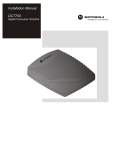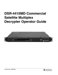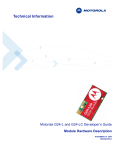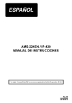
1
Operator’s Guide
DOCSIS® 3.0
Motorola SURFboard® M-eMTA
SBV5506 Chassis
Installation Guide
About This Document
This document provides instructions on installation and connection of cables
and wiring for the M-eMTA device only. Cabling to the facility or external networks are not covered here.
Motorola Part Number: 558005-002-z1
February 2010
Copyright © 2010 Motorola, Inc. All rights reserved. No part of this publication may be reproduced in any form or by any means or used to
make any derivative work (such as translation, transformation, or adaptation) without written permission from Motorola, Inc. Motorola
reserves the right to revise this publication and to make changes in content from time to time without obligation on the part of Motorola to provide notification of such revision or change. Motorola provides this guide without warranty of any kind, implied or expressed, including, but
not limited to, the implied warranties of merchantability and fitness for a particular purpose. Motorola may make improvements or changes in
the product(s) described in this manual at any time.
MOTOROLA and the stylized M Logo are registered in the US Patent and Trademark Office. MediaCipher ® is a registered trademark; all
other Motorola product names are trademarks of Motorola, Inc. Other product or service names that may appear in this document are trademarks of their respective holders.
ii
M-eMTA Installation Guide
Safety Information
Caution
These servicing instructions are for use by qualified personnel only. To reduce the
risk of electrical shock, do not perform any servicing other than that contained in
the Installation and Troubleshooting Instructions unless you are qualified to do so.
Refer all servicing to qualified service personnel.
Special Symbols That Might Appear On the Equipment
This symbol indicates that dangerous voltage levels are present within the equipment. These voltages are not insulated and may be of sufficient strength to cause
serious bodily injury when touched. The symbol may also appear on schematics.
The exclamation point, within an equilateral triangle, is intended to alert the user to
the presence of important installation, servicing, and operating instructions in the
documents accompanying the equipment.
Electrostatic discharge (ESD) can damage the M-eMTA unit and circuit card assemblies. Wear an antistatic wrist strap attached to a chassis ground to prevent ESD damage.
M-eMTA Installation Guide
iii
Regulatory Information
FCC Compliance
This device complies with part 15 of the FCC Rules. Operation is subject to the
following two conditions: (1) This device may not cause harmful interference, and
(2) this device must accept any interference received, including interference that
may cause undesired operation.
Note that this equipment has been tested and found to comply with the limits for
a Class B digital device, pursuant to part 15 of the FCC Rules. These limits are
designed to provide reasonable protection against harmful interference in a residential installation. This equipment generates, uses, and can radiate radio frequency energy and, if not installed and used in accordance with the instruction
manual, may cause harmful interference to radio communications. However,
there is no guarantee that interference will not occur in a particular installation. If
this equipment does cause harmful interference to radio or television reception,
which can be determined by turning the equipment off and on, the user is encouraged to try to correct the interference by one or more of the following measures:
•
Reorient or relocate the receiving antenna.
•
Increase the separation between the equipment and receiver.
•
Connect the equipment into an outlet on a circuit different from that
to which the receiver is connected.
•
Consult the dealer or an experienced radio/TV technician for help.
IMPORTANT:
Any changes or modifications not expressly approved by Motorola for
compliance could void the user’s authority to operate the equipment.
Canada Industry Canada (IC)
This Class B digital device complies with Canadian ICES-003.
Cet appareil numérique de la classe B est conforme à la norme NMB-003 du
Canada.
FCC Declaration of Conformity
According to 47CFR, Parts 2 and 15 for Class B Personal Computers and Peripherals, and/or CPU Boards and Power Supplies used with Class B Personal Computers, Motorola, Inc., 101 Tournament Drive, Horsham, PA 19044, 1 215 323 1000,
declares under sole responsibility that the product identifies with 47CFR Part 2
and 15 of the FCC Rules as a Class B digital device. Each product marketed is
identical to the representative unit tested and found to be compliant with the
standards. Records maintained continue to reflect the equipment being produced
can be expected to be within the variation accepted, due to quantity production
and testing on a statistical basis as required by 47CFR 2.909.The above named
party is responsible for ensuring that the equipment complies with the standards
of 47CFR, Paragraph 15.101 to 15.109.
NOTE:
iv
Your service provider, not Motorola, is responsible for the provision of
VoIP telephony services through this equipment. Motorola shall not be
liable for, and expressly disclaims, any direct or indirect liabilities, damages, losses, claims, demands, actions, causes of action, risks, or harms
arising from or related to the services provided through this equipment.
M-eMTA Installation Guide
Caring For the Environment by Recycling
When you see the following symbol on a Motorola product, do not dispose of the
product with residential or commercial waste.
Recycling Your Motorola Equipment
Please do not dispose of this product with your residential or commercial waste.
Some countries or regions, such as the European Union, have set up systems to
collect and recycle electrical and electronic waste items. Contact your local
authorities for information about practices established for your region. If collection
systems are not available, call Motorola Customer Service for assistance. Please
visit www.motorola.com/recycle for instructions on recycling.
M-eMTA Installation Guide
v
vi
M-eMTA Installation Guide
Table of Contents
Chapter 1
Introduction .................................................................................................................................. 1
Intended Audience ..................................................................................................................... 1
Contact Information.................................................................................................................... 1
SBV5506 Chassis Overview ....................................................................................................... 1
Chassis Components .............................................................................................................. 3
Backplane Components .......................................................................................................... 4
Rear Chassis Components...................................................................................................... 5
Wall Bracket Components ...................................................................................................... 6
Conduit/Cable Grip Components ............................................................................................ 6
M-eMTA Component Overview Descriptions ............................................................................ 7
Power Supply .......................................................................................................................... 7
Blades ..................................................................................................................................... 8
Hot Swappable and Field Replaceable Chassis Components ................................................. 9
Optional Accessories .............................................................................................................. 9
Safety Precautions and Warnings ........................................................................................... 9
Chapter 2
Pre-Installation ............................................................................................................................ 11
Pre-Installation Checklist ........................................................................................................... 11
Hardware ............................................................................................................................... 11
Basic Tools ............................................................................................................................. 11
Cables and Wiring.................................................................................................................. 12
Identifying a Location for Installation......................................................................................... 12
Identifying Building Material Suited for Installation................................................................ 12
Chapter 3
Hardware Installation ................................................................................................................ 13
Overview ................................................................................................................................... 13
Grounding and Cabling the Chassis........................................................................................... 13
Connect the Grounding Wire ................................................................................................. 14
Grounding Instructions for AC Facility Power Source Options ........................................... 14
Grounding Instructions for AC HFC and UPS DC Power Options....................................... 15
Connect the Telephone Cables .............................................................................................. 15
RJ-21 Cable ........................................................................................................................ 15
Punch-Down Terminal......................................................................................................... 16
Connect the Data Cable(s) ..................................................................................................... 16
Connect the RF Cable ............................................................................................................ 16
Connect the Power Cables .................................................................................................... 17
Connecting the AC Facility Power Source (Hardwire) ....................................................... 18
Connecting the Power and Jumper Cables (Indoor or Outdoor) .................................... 18
M-eMTA Installation Guide
vii
Connecting the AC Facility Power Source (Power Cable to Indoor 120 VAC Outlet) ......... 20
Connecting the Power and Jumper Cables (Indoor Configuration Only) ....................... 20
Connecting the AC HFC Power Source ............................................................................. 23
Connecting the M-eMTA From the HFC Plant ............................................................... 23
Connecting the UPS DC Power Source............................................................................. 25
Installing the Wall Bracket ........................................................................................................ 26
Required Tools ...................................................................................................................... 26
Wall Bracket Installation........................................................................................................ 27
Mounting the Chassis Onto the Wall Bracket........................................................................... 29
Installing the Power Supplies and the Blades........................................................................... 29
Installing the Power Supplies................................................................................................ 29
Installing the Blades.............................................................................................................. 29
Securing the Cables ................................................................................................................. 31
Securing the AC Facility Power Cable ................................................................................... 31
Securing the Cables Using Cable Ties .................................................................................. 31
Securing the Chassis ................................................................................................................ 32
Replacing the Fuses ................................................................................................................. 32
Chapter 4
Troubleshooting ......................................................................................................................... 33
Appendix A
Technical Specifications............................................................................................................. 35
viii
M-eMTA Installation Guide
Chapter 1
Introduction
This document provides installation and cabling instructions for the M-eMTA device, not cabling to
the facility or external networks. For quick access and ease of use, this document is divided into
the following key sections:
•
“SBV5506 Chassis Overview” on page 1
•
“Pre-Installation” on page 11
•
“Hardware Installation” on page 13
•
“Troubleshooting” on page 33
•
“Technical Specifications” on page 35
Intended Audience
This document is intended for trained service personnel only. The instructions
provided in this document assume that the reader (trained service personnel only)
has knowledge of National Electrical Code (NEC), and local codes. Individuals not
meeting these basic requirements should not attempt to install, open, or operate
the M-eMTA device.
Contact Information
For questions or comments regarding features, functionality, resolved/open
issues, contact Motorola’s Technical Support Center at 800 MOT-WIRE (668-9473)
or visit our website at https://mynetworksupport.motorola.com.
SBV5506 Chassis Overview
The Motorola SURFboard M-eMTA chassis is available in two configurations:
6-slot or 12-slot. The 6-slot version is a drop-in replacement for existing equipment no longer supported by the vendor.
Chassis Model Number
# of Slots
# of Voice Lines
# of Subscribers
SBV5506
6
Up to 24
Up to 6 or 24*
SBV5512
12
Up to 48
Up to 12 or 48*
* Dependent on the provisioning capabilities of the Multiple System Operator (MSO).
1
Each chassis consists of the assembly to hold the blades, the input connection for
the Hybrid Fiber/Coax (HFC) RF connector, the input power connections, the output telephone connections, and the high-speed data connections. The backplane
has 6-layer construction, contains RF, telephone, Ethernet, power signals, and a
ground plane.
The chassis also incorporates an RF signal switching system that terminates the
RF signal into a load whenever there is no blade in a slot. This system design
maintains the impedance seen by the blades in the M-eMTA to minimize reflections within the chassis. The one RF input to the SBV5506 splits to the six slots
on the back plane.
Both the downstream and upstream input levels are maintained using amplifiers
to achieve a near unity gain through the back panel.
The following illustration shows the front and side views of the SBV5506 chassis.
2
M-eMTA Installation Guide
Chassis Components
This section provides an overview of the SBV5506 chassis components.
Key
Component Name
1
Break-resistant window (coated with EMI/UV Film)
2
Panel fastener
3
Door ground wire
4
Gasket
5
Wiring diagram label
6
#1 Conduit/cable grips – All-power cables (AC or DC) and ground cable
7
#2 Conduit/cable grips – RF input
8
#3 Conduit/cable grips – All Ethernet and all telephone lines
9
Cable strain relief bracket
10
Tamper switch (normally closed)
11
Padlock slot
Chapter 1: Introduction
3
Backplane Components
The following illustration provides an overview of the SBV5506 backplane components.
Key
4
Component Name
1
Power Supply Enclosure Area
2
Upper Card Guide
3
Blade Enclosure Area
4
Lower Card Guide
5
RJ–45 Ethernet Connectors
6
Telephone Line Punch Down Terminals
7
Fuses (F1 and F2)
8
Left AC Terminal Block (AC1)
9
Left AC Surge Protector (SP1)
10
Right AC Terminal Block (AC2)
M-eMTA Installation Guide
Key
Component Name
11
Right AC Surge Protector (SP2)
12
Ground Assembly
13
F–Connector
14
UPS DC Terminal Block
15
UPS DC Surge Protector (SP3)
16
Fuse (F3)
17
Telephone Line RJ–21 Connector
Rear Chassis Components
The following illustration provides an overview of the SBV5506 rear chassis components.
SBV5506 Backplane
Chapter 1: Introduction
Component Name
1.
Mounting Flange
2.
Heat Sink
3.
Mounting Cleats
5
Wall Bracket Components
The following illustration provides an overview of the SBV5506 wall bracket components.
Wall Bracket
Component Name
1.
Wall mounting holes
2.
Cleat Slots
Conduit/Cable Grip Components
Perform a visual check of the cabling conduits installed on the bottom of the
SBV5506 chassis. Use the diagram and chart below to verify proper installation of
the conduits.
Conduit/Cable Grips
6
Component Name
1.
#1 Conduit/cable grips – All-power cables
(AC or DC) and ground cable.
2.
#2 Conduit/cable grips – RF input.
3.
#3 Conduit/cable grips – All Ethernet and
all telephone lines.
M-eMTA Installation Guide
M-eMTA Component Overview Descriptions
This section provides an overview of the M-eMTA components.
Power Supply
The chassis can accept a nominal input of 90 VAC (70 VAC lower limit) from the
HFC network, +12VDC UPS power, or up to 120 VAC from facility power:
•
HFC Network Power – Power source is derived from the normal HFC
90 VAC power on the cable plant and is extracted for M-eMTA use
with a readily available power tap with a Siamese twisted pair power
output. This power input is routed to internal supplies that convert
the AC input to +12 VDC output for the M-eMTA blades and chassis.
•
UPS Power – Power is supplied by a local UPS battery backup system
that supplies +12 VDC to the M-eMTA. Note that no power supply
modules are installed for this powering option.
•
AC Facility – Power is derived from a standard 120 VAC at the installation location. This power input is routed to internal supplies that convert the AC input to +12 VDC output for the M-eMTA blades and
chassis.
WARNING: Although different power configurations are available, only one
powering option can be used at a time.
When servicing requires the equipment to be powered down, make sure
all power sources have been disconnected.
The following illustration provides an overview of the power supply.
Power Supply
Chapter 1: Introduction
Component Name
1.
Power supply module
(Not used for UPS-powering of
the M-eMTA.)
2.
AC OK LED – When the LED is
solid green, the AC input voltage to the power supply is
within specification.
3.
DC OK LED – When the LED is
solid green, the DC output voltage from the power supply is
within specification.
4.
T10 Torx screws
7
Blades
The 2-line blade is based on Motorola’s SURFboard SBV5222 digital voice
modem, while the 4-line blade is based on Motorola’s SURFboard SBV5322 digital voice modem.
NOTE:
The 2-port and 4-port blades are also available with a diagnostic port
(optional).
eMTA Module Number
# of Lines
# of Subscribers
SBV5622
2
1 or 2*
SBV5642
4
1 to 4*
* Dependent on the provisioning capabilities of the Multiple System Operator (MSO).
The following illustration provides an overview of the blade components.
Blade
NOTE:
8
Component Name
1.
Upper inject/eject handle
2.
LEDs
3.
RJ-11 test ports
4.
Lower inject/eject handle
In the previous example, the inject/eject handles are in the unlocked position. When inserting blades into the chassis, make sure that the handles
are in the unlocked position, and then lock the handles to secure the
blade in the chassis following insertion. For more information, see
“Installing the Blades” on page 29
M-eMTA Installation Guide
Hot Swappable and Field Replaceable Chassis Components
The blades and the power supply modules are hot swappable, and the following
components are field replaceable:
•
Blades
•
Power supply modules
•
Surge protectors (SP1, SP2, and SP3)
•
Fuses (F1, F2, and F3)
Optional Accessories
Order the items listed below to aid in M-eMTA installation:
•
AC power cable kit – Use the 110 V power cable for AC facility connections.
•
RJ-21 cable kit – Use the cable to quickly connect telephony features.
•
100-pin external punch down block – Use with the RJ-21 cable to connect additional telephone lines external to the M-eMTA.
Safety Precautions and Warnings
CAUTION: When working with the M-eMTA, be aware of the following
safety precautions and warnings:
•
•
•
•
•
•
Only qualified service personnel should install this device.
Improper grounding may damage the M-eMTA.
Refer to National Electrical Code (NEC) guidelines and/or local regulations for the M eMTA grounding to the building grounding system.
Disconnect TNV circuit connector(s) before disconnecting power.
The Motorola SURFboard M-eMTA accepts a maximum voltage of
120V. Because of the voltage levels, there is a risk of electrical shock.
Follow the NEC recommendations to avoid electric shock.
In accordance with NEC 725 and 800, all output conductors routed
outside of the building are required to be less than 140 feet, and there
must be adequate clearance from power and lightning conductors.
Chapter 1: Introduction
9
10
M-eMTA Installation Guide
Chapter 2
Pre-Installation
Before you begin the M-eMTA hardware installation, make sure that you have the required tools
and equipment and that you have identified the proper location to mount the SBV5506 chassis.
Pre-Installation Checklist
The following hardware, tools, cables, and wiring are required for the M-eMTA
installation.
Hardware
Note that the chassis are shipped without the power supplies and blades
installed. The number of power supplies and blades varies according to the customer’s requirements. Before you begin, do the following:
•
Check chassis exterior and interior for damaged, missing, or loose
parts.
•
Verify that you have all of the components (power supply and blades)
that are required for the installation.
•
Verify that the accessory kit is complete. (See the parts list included
with the kit.)
•
Check the wall bracket for damage.
Basic Tools
The following basic tools are required for the M-eMTA installation:
•
Chalk
•
Punch-down tool
•
Drill
•
Safety glasses
•
Drill bits
•
Socket (3/8”)
•
Dust mask
•
Socket (7/16”)
•
ESD band
•
Torx T10 screwdriver
•
Flat head screwdriver (4 mm)
•
Voltmeter
•
Level
•
Wire-cable cutters
•
Permanent marker
•
Wire strippers
•
Phillips screwdriver
11
Cables and Wiring
The following cables and wiring are required for the M-eMTA installation:
•
Coaxial cable – RG6 or RG59 diameter cable.
•
HFC powering cable – 18 to 22 AWG (0.8 to 0.6438 mm2 cross-sectional area – twisted pair). Note that this cable is only used for the
HFC powering option.
•
AC powering cable – See “Connecting the AC Facility Power Source
(Power Cable to Indoor 120 VAC Outlet)” on page 20. Note that this
cable is only used for the AC powering option.
•
Ground wire – 6 to 12 AWG (13 to 3 mm2 cross-sectional area – insulated strand or solid).
•
Jumper wires – Only used for the AC Powering option.
Identifying a Location for Installation
Before selecting a location to mount the SBV5506 chassis, consider the following:
•
When mounted to a permanent surface (i.e., an apartment building,
not a temporary storage unit), is there a minimum 2” clearing on the
left to ensure that the chassis door can open?
•
Can service personnel easily access the unit to perform routine maintenance, testing, updates, etc?
•
Is the location close to the necessary power source?
•
Is the location in close proximity to the necessary protective ground
connection?
Identifying Building Material Suited for Installation
The unit can be mounted to most building materials including the following:
•
Siding (aluminum and vinyl)
•
Stucco (brick and block fascia)
•
Brick and concrete
•
Cinder blocks and hollow walls
•
Wood
•
Drywall.
WARNING: Before installing the SBV5506 onto a brick or cinder block
wall, first determine that the wall is made of the true material and not fascia. Ensure that the fasteners are completely set into the hollow sections
of the cinder block. Do not attempt to install the fasteners into the mortar
between the blocks. Only qualified service personnel should install this
device.
12
M-eMTA Installation Guide
Chapter 3
Hardware Installation
This chapter provides information for installing the M-eMTA hardware. Cabling the M-eMTA is easier when placed on a flat level surface. When possible, Motorola recommends making the connections inside the box prior to permanently mounting the chassis.
Overview
To complete the M-eMTA installation, you must perform the procedures in the following sections:
•
Grounding and Cabling the Chassis, page 13
•
Installing the Wall Bracket, page 26
•
Mounting the Chassis Onto the Wall Bracket, page 29
•
Installing the Power Supplies, page 29
•
Installing the Blades, page 29
•
Securing the Cables, page 31
•
Securing the Chassis, page 32
Grounding and Cabling the Chassis
The following sections explain how to prevent personal injury or damage to the
product. Make connections to the M-eMTA device in the following sequence:
1.
Connect the Grounding Wire, page 14
2. Connect the Telephone Cables, page 15
3. Connect the Data Cable(s), page 16
4. Connect the RF Cable, page 16
5. Connect the Power Cables, page 17
NOTE:
For an overview of the SBV5506 conduit and cable grips, see “Conduit/
Cable Grip Components” on page 6.
13
Connect the Grounding Wire
The SBV5506 chassis must be grounded to the facility. Select the grounding
instruction applicable to the corresponding powering option.
WARNING: Review the following safety precautions before installing the
unit:
•
Improper grounding may damage the M-eMTA. Refer to National Electrical Code (NEC) guidelines and/or local regulations for the M-eMTA
grounding to the building grounding system.
Ensuring that the customer has proper protective ground for the
SBV5506 is a safety, liability, and service related requirement. Many
ground scenarios are possible on the customer’s property. Install a 6 to
14 AWG (13 to 3 mm2 cross sectional area) ground wire from the
ground stud on the SBV5506 to the electrical service ground electrode.
Motorola recommends using a 6 AWG (13 mm2) wire for maximum
protection. If it is not possible to connect the SBV5506 to the electrical
service ground, connect the ground wire to the SBV5506 ground lug
and an appropriate earth ground.
Always attach the ground wire first, and always remove the ground
wire last.
•
•
•
Grounding Instructions for AC Facility Power Source Options
Follow these grounding instructions:
1.
Open the chassis door using a Phillips or flathead screwdriver to loosen the
panel fasteners.
2. Loosen the dome nut on the conduit/cable grips.
3. Remove the protective shields covering the AC and UPS terminal blocks.
4. Loosen the grounding terminal using a flathead screwdriver.
5. Insert one AC power cable through conduit/cable grip #1.
NOTE:
14
Pull enough cable through the conduit to wrap around the cable strain
relief bracket (approximately 22”). Installers may need to place the AC
power cable into a ¾” conduit hose prior to cabling. Refer to NEC guidelines and/or local regulations.
M-eMTA Installation Guide
6. Thread the AC power cable downward through the first opening on the Cable
Strain Relief Bracket.
7.
Wrap the excess cable around the Cable Strain Relief Bracket.
8. Remove approximately a ½” of insulation from the green ground wire to
expose the copper.
9. Insert the ground wire (from the right) into the bottom of the grounding terminal.
10. Tighten the grounding terminal to secure the wire. for more information, see
“Securing the Cables” on page 31.
Grounding Instructions for AC HFC and UPS DC Power Options
Follow these grounding instructions:
1.
Open the chassis door using a Phillips or flathead screwdriver to loosen the
panel fasteners.
2. Loosen the dome nut on the conduit/cable grips.
3. Remove the protective shields covering the AC and UPS terminal blocks.
4. Loosen the grounding terminal using a flathead screwdriver.
5. Insert the ground wire through conduit/cable grip #1.
6. Wrap the excess wire around the cable strain relief bracket.
7.
Insert the ground wire (from the right) into the bottom of the grounding terminal. (Verify that the copper is exposed if the wire is insulated).
8. Tighten the ground terminal to secure the wire. For more information, see
“Securing the Cables” on page 31.
Connect the Telephone Cables
The M-eMTA has two options for connecting telephone cables:
•
RJ-21
•
Punch down terminals
NOTE:
•
Do not connect the RJ-21 and the punch down terminals; use
one option only.
•
The maximum ring loading across all telephone lines in the
SBV5506 is 20REN. The maximum per blade is 5REN per
port and 10REN total.
RJ-21 Cable
Follow these steps to connect the RJ-21 cable:
1.
Insert the RJ-21 cable through the coupling #3.
2. Connect the RJ-21 cable to the RJ-21 connector on the backplane.
3. Tighten the cable using a screwdriver.
4. Secure the RJ-21 cable with a cable tie. For more information, see “Securing
the Cables” on page 31.
Chapter 3: Hardware Installation
15
Punch-Down Terminal
Follow these steps to connect the punch down terminal:
1.
Insert telephone cables through the #3 coupling.
2. Lift the first punch down terminal.
3. Insert the individual strands (Tip = green, Ring = red).
4. Return the punch down terminal to the down position.
5. Repeat steps 1–4 for additional phone lines.
6. Secure the telephone lines with a cable tie. For more information, see
“Securing the Cables” on page 31.
Connect the Data Cable(s)
Follow these steps to connect the data cable(s):
1.
Insert the Ethernet (RJ-45) cable through the #3 coupling.
2. Connect the Ethernet cable to the Ethernet ports on the backplane.
3. Repeat steps 1 and 2 for additional lines.
4. Secure the cable using a cable tie. For more information, see “Securing the
Cables” on page 31.
NOTE:
The data ports can supply up to 3W maximum (18W total) to power an
external MoCA bridge device, Power Over Ethernet (POE).
Connect the RF Cable
Follow these steps to connect the RF connector:
1.
Measure the RF power level to ensure that it is between -5dBmV and
+10dBmV.
2. Insert the coaxial cable through the #2 coupling.
3. Route and connect the cable to the F–type connector on the backplane.
(Torque to 15–20 in-lbs.)
4. Secure the cable using a cable tie. For more information, see “Securing the
Cables” on page 31.
16
M-eMTA Installation Guide
Connect the Power Cables
CAUTION: Although different power configurations are available, only
one powering option can be used at a time. When servicing requires the
equipment to be powered down, make sure all power sources have been
disconnected.
Depending on your situation, there are three options available for supplying power
to the SBV5506 chassis. Select from one of the following:
•
Facility Power 120 VAC – Choose from one of the following two
options:
>
“Connecting the AC Facility Power Source (Hardwire)” on
page 18
>
“Connecting the AC Facility Power Source (Power Cable to
Indoor 120 VAC Outlet)” on page 20
•
90 VAC from HFC Plant – Power the unit using a tap and the plant
cable as the power-generating source. For more information, see
“Connecting the AC HFC Power Source” on page 23.
•
UPS DC – Power the unit using an uninterruptible power source
(UPS). For more information, see “Connecting the UPS DC Power
Source” on page 25.
NOTE:
For outdoor installations, only use a UPS that is approved for outdoor
usage.
Chapter 3: Hardware Installation
17
Connecting the AC Facility Power Source (Hardwire)
CAUTION: USE only one powering option at a time.
•
To avoid personal injury, follow the NEC guidelines and/or local regulations during the installation.
When using the facility power, the SBV5506 should be connected to a
20-amp branch circuit that is part of the building installation. A licensed
electrician may be required to make this connection.
Wire the power cables to the SBV5506 before making connection to
the facility power.
To turn the unit on and off; the power cables connecting the unit to the
facility power acts as the disconnect device.
•
•
•
Connecting the Power and Jumper Cables (Indoor or Outdoor)
Follow these steps when connecting the power and jumper cables:
1.
Connect the ground wire. For more information, see “Connect the Grounding
Wire” on page 14.
2. Ensure that the telephone, data, and the RF-Connector cables are properly
attached. For more information, see “Grounding and Cabling the Chassis” on
page 13.
3. Follow these steps to remove the four bus-bars:
•
Remove screws 1 and 3 on the AC1 and AC2 terminal blocks.
•
Loosen (do not remove) the screws on the SP1 and SP2 surge
protectors.
•
Remove the four bus bars.
•
Retighten the SP1 and SP2 nuts after removing the bus-bars.
4. Connect the power cables and one end of the jumper cables to the AC1 terminal block.
NOTE:
18
Place the flat side of the ring terminals back-to-back before inserting the
screws. Hot cables [black] = screw 1, neutral cables [white] = screw 3.
M-eMTA Installation Guide
5. Connect the other end of each jumper cable to the AC2 terminal block.
NOTE:
Hot [black] = screw 1, neutral [white] = screw 3.
6. Secure the power cable using the strain relief bushing. For more information,
see “Securing the Cables” on page 31. Note that any cabling outside the interior of the premise should be contained inside a conduit.
WARNING: You must put on an Electrostatic Discharge (ESD) wristband
before continuing.
7.
Slide the AC power supply modules (left and right) into the power supply
enclosure area.
8. Insert the blade(s) into the chassis. For more information, see “Installing the
Blades” on page 29.
9. Reattach the protective shields over the AC1 and AC2 terminal blocks.
10. Place the chassis onto the wall mount bracket. For more information, see
“Mounting the Chassis Onto the Wall Bracket” on page 29.
11. Connect to facility power.
12. Verify that the unit is operational by observing the LED’s on the blades, checking for a dial tone, and sending/receiving calls.
Chapter 3: Hardware Installation
19
Connecting the AC Facility Power Source (Power Cable to Indoor
120 VAC Outlet)
CAUTION: Use only one powering option at a time.
•
To avoid personal injury, follow the NEC guidelines and/or local regulations during the installation.
Only use power cables that meet the NEC guidelines and/or local regulations.
When using the facility power, the SBV5506 should be connected to a
20 amp branch circuit that is part of the building installation. A licensed
electrician may be required to make this connection.
The plug on the power cable acts as the power disconnect device for
the unit.
Wire the power cable into the SBV5506 before connecting the plug to
the receptacle (socket outlet).
The power supply cord must not be attached to the building surface or
run through walls, ceilings, floors, and similar openings in the building
structure. For indoor units, the power supply cord must not be installed
in a conduit.
Installation measures must be taken to prevent physical damage to the
power supply cord including proper routing of the power supply cord
and provision of a receptacle (socket outlet) near the SBV5506 or positioning the SBV5506 near a receptacle (socket outlet).
•
•
•
•
•
•
Connecting the Power and Jumper Cables (Indoor Configuration Only)
Follow these steps when connecting the power and jumper cables:
1.
Connect the ground wire. For more information, see “Connect the Grounding
Wire” on page 14.
2. Ensure that the telephone, data, and the RF-Connector cables are properly
attached. For more information, see “Grounding and Cabling the Chassis” on
page 13.
3. Follow these steps to remove the four bus-bars:
20
•
Remove screws 1 and 3 on the AC1 and AC2 terminal blocks.
•
Loosen (do not remove) the screws on the SP1 and SP2 surge
protectors.
•
Remove the four bus bars.
•
Retighten the SP1 and SP2 nuts after removing the bus-bars.
M-eMTA Installation Guide
4. Connect the power cables and one end of the jumper cables to the AC1 terminal block.
NOTE:
Place the flats of the wires back-to-back before inserting the screw. Hot
cables [black] = screw 1, neutral cables [white] = screw 3.
5. Connect the other end of each jumper cable to the AC2 terminal block.
NOTE:
Hot [black] = screw 1, neutral [white] = screw 3.
Chapter 3: Hardware Installation
21
6. Secure the cables using the bushing. For more information, see “Securing
the Cables” on page 31.
WARNING: You must put on an Electrostatic Discharge (ESD) wristband
before continuing.
7.
Slide the AC power supply modules (left and right) into the power supply
enclosure area.
8. Insert the blade(s) into the chassis. For more information, see “Installing the
Blades” on page 29.
9. Reattach the protective shields over the AC1 and AC2 terminal blocks.
10. Place the chassis onto the wall mount bracket. For more information, see
“Mounting the Chassis Onto the Wall Bracket” on page 29.
11. Plug the power supply cord into a 120V electrical outlet.
12. Verify that the unit is operational by observing the LED’s on the blades by
checking for a dial tone and if calls are being sent and received.
22
M-eMTA Installation Guide
Connecting the AC HFC Power Source
CAUTION: The M-eMTA accepts an HFC network voltage of 70 to
90 VAC. Before installing, verify that the HFC network voltage is within
this range.
•
•
•
•
Disconnect the power at the tap before performing this procedure.
To turn the unit on and off; the power cables connecting the unit to the
HFC network power source acts as the disconnect device. Use only
one powering option at a time.
To avoid personal injury, use the NEC guidelines and an ESD wristband
during the installation.
The HFC network power source that connects to the M-eMTA needs
to comply with NEC Article 830.15.
Connecting the M-eMTA From the HFC Plant
The M-eMTA has two AC inputs. Each input powers a corresponding power supply module. Note that the #1 input powers the #1 (left) power supply, and the
#2 input powers the #2 (right) power supply. Together, the two modules provide
power to the blades (up to six) installed in the M-eMTA under the worst case
loading conditions, and provides redundancy under normal load conditions.
It is recommended to feed each of the two M-eMTA’s 90 VAC inputs using a
power-extracting tap with two 480 mA @60c (750 mA @ 25c) current limiters. The
480 mA @60c (750 mA @ 25c) current limiter ensures that the M-eMTA has sufficient power to meet the worst case loading conditions across temperature and
when operating at the end of the line where the input voltage may only be 70
VAC.
Follow these steps when connecting the M-eMTA from the HFC plant:
1.
Connect the ground wire. For more information, see “Connect the Grounding
Wire” on page 14.
2. Verify that the bus bars are installed (connecting the surge protector to the
AC terminal block).
3. Ensure that the telephone, data, and the RF-Connector cables are properly
attached. For more information, see “Grounding and Cabling the Chassis” on
page 13.
4. Insert two (non-powered) AC twisted pair wires through the #1 coupling.
5. Connect the first twisted pair to the AC1 (left) terminal block (black = 1,
white = 2). Repeat the steps to attach the second twisted pair to the AC2
(right) terminal block.
Chapter 3: Hardware Installation
23
6. Secure the power cables using the cable strain relief bracket. For more information, see “Securing the Cables” on page 31.
WARNING: You must put on an Electrostatic Discharge (ESD) wristband
before continuing.
7.
Slide the AC power supply modules (left and right) into the power supply
enclosure area.
8. Insert the blade(s) into the chassis. For more information, see “Installing the
Blades” on page 29.
9. Reattach the protective shields over the AC1 and AC2 terminal blocks.
10. Verify that the unit is operational by observing the LEDs on the blades, checking for a dial tone, and making sure that calls can be made using the telephone lines.
24
M-eMTA Installation Guide
Connecting the UPS DC Power Source
CAUTION: Ensure that the UPS DC power source is not powered.
•
•
•
•
•
To avoid personal injury, use the NEC guidelines during the installation.
To turn the unit on and off; the power cables connecting the unit to the
UPS DC power source acts as the disconnect device.
Do not use the power supply modules with this option.
Use only one powering option at a time.
Use an ESD wrist band during the installation.
Follow these steps to connect the UPS DC power source:
1.
Connect the ground wire. For more information, see “Connect the Grounding
Wire” on page 14.
2. Verify that the bus bars are installed (connecting the surge protector to the
UPS terminal block).
3. Ensure that the telephone, data, and the RF-Connector cables are properly
attached. For more information, see “Grounding and Cabling the Chassis” on
page 13.
4. Measure the voltage from the UPS. Ensure that the voltage measures
between +10 VDC to +14 VDC and that the polarity of the wires is correct
(RED = +12 VDC and Black = 12 VDC return).
5. Turn off the 12 VDC UPS power.
6. Insert the non-powered DC twisted pair wires through the #1 coupling.
7.
Connect the DC twisted pair wires to SP3 (Red =1, Black = 2).
8. Connect the four discrete status lines if applicable [AC Fail (6), REPL BATT (7),
BATT MISS (8), BATT LOW (9) and UPS GND (10)].
WARNING: You must put on an Electrostatic Discharge (ESD) wristband
before continuing.
Chapter 3: Hardware Installation
25
9. Insert the blade(s) into the chassis. For more information, see “Installing the
Blades” on page 29.
10. Reattach the protective shields over the terminal blocks.
11. Place the chassis onto the wall mount bracket. For more information, see
“Mounting the Chassis Onto the Wall Bracket” on page 29.
12. Connect the UPS to the power source to activate the UPS +12 VDC output.
13. Verify that the unit is operational by observing the LEDs on the blades, checking for a dial tone, and making sure calls can be made using the telephone
lines.
14. Secure the power cables using the cable strain relief bracket. For more information, see “Securing the Cables” on page 31.
Installing the Wall Bracket
The wall bracket and screws are shipped with the M-eMTA; they are located in
the foam pocket in the packaging.
CAUTION: Motorola recommends that installers mount the wall bracket
and then cable the M-eMTA before placing the chassis onto the bracket.
Wear safety glasses and a dust mask when performing this procedure.
Required Tools
The following tools are required for mounting the wall bracket:
26
•
Drill
•
Drill bit recommended for the mounting surface
(i.e., 1/8” twist drill bit for siding)
•
7/16” socket or box-end wrench
•
Pencil or medium tip permanent marker
•
Chalk (use a color visible on the mounting surface)
•
Hammer (brick and concrete)
•
Leveling tool
•
Dust mask
•
Safety glasses
•
Anchors and screws (For more information, see the following table.)
M-eMTA Installation Guide
NOTE:
For a cinder block installation, use a screwdriver to tighten the anchors.
If Mounting To...
Cinder Block
Then Use This Hardware
(4) ¼”- 20 hollow wall anchors
(4) ¼”- 20 machine screws
(4) ¼” flat washers
Brick and Concrete
(4) ¼” expansion anchors
(4) ¼” x 2” lag screws
(4) ¼” flat washers
Siding
(4) ¼” x 3” lag screws
(4) ¼” flat washers
Wood
(4) ¼” x 2” Wood screws
(4) ¼” flat washers
Wall Bracket Installation
Follow these steps to mount the wall bracket:
1.
Depending on the height of the installer, position the wall bracket on the
installation surface approximately 36 to 42 inches off the ground.
NOTE:
The SBV5506 chassis is approximately 24 inches in length. If the wall
bracket is positioned too high off the ground, you will have difficulty
reaching the mounting flanges on the rear of the SBV5506 chassis when
you mount the chassis to the wall bracket.
For siding and applicable wood installations, locate the wood stud and
then position the wall bracket. For best results, ensure that the mounting
holes are directly in the middle of the stud.
2. When you position the wall bracket, place a leveling tool across the top of the
wall bracket to verify that the bracket is level.
3. Use a pencil and mark the location of the wall mounting holes.
4. Refer to the following diagram and mark the location of the Mounting Flange
holes on the chassis.
NOTE:
The diagram is not drawn to scale. All measurements should be performed with a measuring device, such as a tape measure, and a level.
The distance between the wall mounting bracket holes is 9 inches, and
the distance between the wall mounting bracket holes and the Mounting
Flange holes on the chassis is 19.67 inches.
Chapter 3: Hardware Installation
27
5. Drill the pilot holes. (Skip this step if the surface is wood.)
NOTE:
Due to the expansion and contraction of vinyl and aluminum siding during
changes in temperature most manufacturers recommend drilling mounting holes larger than the screw or bolt diameter. Please consult the siding
manufacturer for specific information. Do not over tighten the lag screws
on vinyl siding since this prevents free movement when expansion
occurs.
When installing the chassis on vinyl or aluminum siding, drill the manufacturer’s recommended oversize hole in the siding before drilling the pilot
hole in the material under the siding. For brick or concrete block installation, follow the recommendations of the anchor manufacturer, and insert
each anchor flush with the wall surface.
6. Secure the wall bracket to the surface using the washers and lag screws.
7.
28
Tighten the screws securely, but do not over-tighten the screws because it
can cause damage to the surface.
M-eMTA Installation Guide
Mounting the Chassis Onto the Wall Bracket
Prior to mounting the SBV5506 chassis onto the wall bracket, verify the following:
•
Wall bracket is securely attached to the structure.
•
Pilot holes for the Mounting Flange on the chassis have been drilled.
(Unless the surface is wood.)
•
Panel fasteners around the perimeter of the chassis door are
engaged to prevent the door from opening during the installation.
Follow these steps to mount the chassis onto the wall bracket:
1.
Carefully lift the chassis to the approximate height of the mounting bracket.
2. Lower the chassis until the chassis mounting cleats slide into the cleat slots
in the wall bracket.
NOTE:
Place a chalk line on the wall as a visual aid to prevent possible damage to
the heat sink.
3. Hold the top of the chassis in place while fastening the unit to the wall. For
the appropriate fastener, refer to the table in “Required Tools” on page 26.
Installing the Power Supplies and the Blades
Install the power supplies before you install the blades.
WARNING: You must use an ESD wristband while performing these
tasks.
Installing the Power Supplies
Follow these steps to install the power supplies:
1.
Align the power supply with power supply guide rails in upper part of the
chassis.
2. Slide the power supply using the front handle until the rear connector mates.
3. Secure the power supply by tightening the two T10 Torx screws that are
located on the power supply faceplate. Torque each screw to 1–2 in-lbs.
4. Repeat the first three steps for the second power supply unit.
Installing the Blades
Follow these steps to install the blades:
1.
Before inserting the blade, carefully remove the protective film from the rear
heatsink block of the blade.
2. Verify that the inject/eject handle of the blade is in the unlocked position by
pressing the top handle up and the bottom handle down.
Chapter 3: Hardware Installation
29
3. Insert the blade into the first slot in the SBV5506 chassis.
4. Push the blade into place using the ejector handles.
5. Lock the blade into place by pressing the top handle down and the bottom
handle up.
Push to lock
6. Repeat steps 1–5 to install additional blades.
30
M-eMTA Installation Guide
Securing the Cables
After the SBV5606 chassis has been mounted on the wall, installers must secure
all cables in the M-eMTA using the cable strain relief bracket. Follow the steps
below to secure the telephone cables, data cables, RF cables, and power cables
for UPS connections.
The following tools are required:
•
UL-approved Liquid-Tuff™ Type LFMC ¾” flexible conduit hose (for
conduits 1 and 2)
•
UL-approved Liquid-Tuff™ Type LFMC 1” flexible conduit hose (for
conduit 3)
•
Large wire cutter or tin-snips
•
(2) 5” Nylon Cable Ties (40 pound tensile strength)
•
Wire cutter
•
4 mm slotted flathead screwdriver
•
Pliers
NOTE:
Installers must place the AC power cable into a ¾” conduit hose prior to
cabling. Refer to the NEC guidelines and/or local regulations.
Securing the AC Facility Power Cable
Follow these steps to secure the AC facility power cable:
1.
Use the bushing to secure the AC power cable to the cable strain relief
bracket.
2. Place the strain relief bushing around the power cable.
3. Squeeze the clasp to close the bushing.
4. Slide the bushing down the power cable into the first opening on the strain
relief bracket.
5. Push the bushing into place by using the pliers to compress the clasp while
inserting the bushing into bracket hole.
6. Verify that the cable is secure in the strain relief bracket.
Securing the Cables Using Cable Ties
Follow these steps to secure the cables using the cable ties:
1.
Measure the amount of flexible conduit hose to cover the length from conduit
glands on the chassis to the boundary where the cables enter the premises.
NOTE:
Any cabling outside of the premises should be contained inside a conduit.
2. Feed appropriate cables through flexible conduit hose and conduit glands into
interior of the chassis.
3. Pull the cables for each conduit up vertically 1.5” creating slack.
4. Thread two cable ties through the strain relief bracket.
5. Apply two cable ties to bundle near conduit couplings.
Chapter 3: Hardware Installation
31
NOTE:
Space the cable ties approximately 2 inches from each other. Do not fully
tighten the bundle cable ties.
6. Feed the secured cable tie through the bundle cable ties and tighten.
7.
Trim the excess material from the cable ties using wire cutter.
Securing the Chassis
After completing the installation, close the door, torque the panel fasteners to
20 in-lbs., and insert and close a lock in the padlock slot on the door.
Replacing the Fuses
Prior to replacing the F1, F2, and F3 fuses, make sure that all power sources have
been disconnected. Only replace with the following types of fuses:
•
F1 and F2 – (2A/250V/IEC 60127-3/IV, T)
•
F3 – (10A/250V/IEC 60127-3/IV, T)
The fuses are located on the SBV5506 backplane. All of the fuses are field
replaceable and can be removed and inserted into the fuse holders by pulling or
pushing on them. For more information, see “Backplane Components” on
page 4.
32
M-eMTA Installation Guide
Chapter 4
Troubleshooting
This section provides basic solutions for problems that installers might encounter. For additional
assistance, please contact Motorola Technical Support for a complete copy of the latest Motorola
eMTA Troubleshooting Guide.
Description of the Problem
Solution
POWER
The LEDs on the power supply module and/or
the Blade(s) are not on.
•
•
•
The LEDs indicate abnormal on the power supply module and/or the blade(s):
•
•
Verify that the HFC Power is properly connected. (See Connecting the AC HFC Power
Source.) For more information, see “Connecting the AC HFC Power Source” on
page 23. Verify that F1 and F2 are installed
and not open.
Verify that the Facility Power is properly connected. For more information, see “Connecting the AC Facility Power Source
(Hardwire)” on page 18. Verify that F1 and
F2 are installed and not open.
Verify that the UPS power is properly connected. For more information, see “Connecting the UPS DC Power Source” on
page 25. Verify that F3 is installed and not
open.
•
•
Replace the power supply module.
Replace the blade after verifying that the
power supply is working properly or that the
UPS input is working.
•
Verify the connection and the RF input level
to the M-EMTA.
Verify that the upstream plant is working
properly.
Verify the provisioning server is working
properly.
If the Power Supply AC LED is on, but the
DC LED is off, or
The Blade Power indicator is off...
RF
•
•
•
Blades cannot find the DS.
Blades cannot complete US power ranging.
Blades do not come on-line.
•
•
33
Description of the Problem
Solution
TELEPHONE
•
•
Telephone lines are not provisioned as indicated by blade indicators.
Blade telephone indicators are normal, but
the telephone functions are not operational.
•
•
Verify the provisioning server is working
properly.
Verify the telephone test ports and backplane wiring.
DATA
•
•
Blade link line indicator is not on.
No connectivity.
•
•
Verify the Ethernet connection(s) on the
backplane.
Ping 192.168.100.1 using an Ethernet connection on the backplane.
TELEMETRY
•
•
•
UPS
Door Lock
Blade specific
•
•
•
34
Manually ground the inputs and verify the
toggle.
Push the door switch and verify the toggle;
manually short the door switch wires and
verify the toggle.
If the other blades are working properly,
then swap out the irregular blade to determine if the problem is with the component
or the slot.
M-eMTA Installation Guide
Appendix A
Technical Specifications
The M-eMTA has the following technical specifications. Note that these specifications are subject
to change without notice.
General Specifications
Cable Interface
F–connector, female, 75 Ω
Network Interface
10/100 Ethernet
Data Protocol
TCP/IP
Dimensions (6–slot chassis)
22”H x 10.5”D x 12”W
Weight (6–slot chassis)
Approximately 24 pounds (Approximately 36 pounds if fully populated.)
Mounting
Wall mountable
Window
Break-resistant, allows quick and easy viewing of eMTA module
and power supply LEDs without opening chassis door.
Power
Power*
4W (nominal) per card
Input
North America—90 VAC (HFC Power) + 12 VDC (UPS Power)
*. The maximum SBV5506 Input power is 80W, which is for a 24-line operation and a 20REN maximum ring load.
Environment
Operating Temperature
–40° C to +60° C
(–40° F to +140° F)
Storage Temperature
–40° C to +70° C
(–40° F to +158° F)
Relative Humidity
0 to 95% R.H. (non-condensing)
Thermal Management
Passive Thermal Management (no fans or moving parts)
35
Downstream
Modulation
64 or 256 QAM
Max. Data Rate*
38 Mbps
(256 QAM at 5.361 Msym/s)
Bandwidth
6 MHz
Symbol Rates
64 QAM 5.069 Msym/s
256 QAM 5.361 Msym/s
Operating Level Range
-15 to +15 dBmV
Frequency Range
88 to 860 MHz (edge to edge)
Input Impedance
75 Ω (nominal)
*. When comparing download speeds with a traditional 28.8k analog modem. Actual speeds will vary, and are often
less than the maximum possible. Upload and download speeds are affected by several factors including, but not limited to, network traffic and services offered by your cable operator or broadband service provider, computer equipment, type of service, number of connections to server, and availability of Internet router(s).
Upstream
Modulation
8*, 16, 32*, 128* QAM or QPSK
Maximum Channel Rate†
30 Mbps
Bandwidth
200 kHz, 400 kHz, 800 kHz, 1.6 MHz, 3.2 MHz, 6.4* MHz
Symbol Rates
160, 320, 640, 1280, 2560, and 5120* ksym/s
Operating Level Range
A-TDMA
8 to 54 dBmV (32 QAM, 64 QAM), 8 to 55 dBmV (8 QAM, 16 QAM)
8 to 58 dBmV (QPSK)
S-CDMA
8 to 53 dBmV (all modulations)
Output Impedance
75 Ω (nominal)
Frequency Range
5 to 42 MHz (edge to edge)
*. With A-TDMA- or S-CDMA-enabled Cable Modem Termination System (CMTS). Certain features may not be activated by your service provider, and/or their network settings may limit the feature’s functionality. Additionally, certain
features may require a subscription. Contact your service provider for details. All features, functionality, and other
product specifications are subject to change without notice or obligation. Your service provider, not Motorola, is
responsible for the provision of Voice-over-IP (VoIP) telephony services through this equipment. Motorola shall not
be liable for, and expressly disclaims any direct or indirect liabilities, damages, losses, claims, demands, actions,
causes of action, risks, or harms arising from or related to the services provided through this equipment.
Important: Be aware that you will not be able to make any calls using this VoIP device if your broadband connection
is not functioning properly.
†. Actual data throughput will be less due to physical layer overhead (error correction coding, burst preamble, and
guard interval).
36
M-eMTA Installation Guide
Software
SIP*
Support Session Initiation Protocol (SIP)
NCS*
Support Network Call Signaling (NCS)
*. SBV56xx modules will support either SIP OR NCS, not both at the same time.
Data
6 Data Ports for SBV5506
10/100 Ethernet
MoCA-Powering on Power Over Ethernet (POE)*
*. The maximum loading for each of the (6) data ports MoCA powering (POE) should not exceed 3W (18W total).
Telemetry*
AC Fail (UPS)
Replace Battery (UPS)
Battery Missing (UPS)
Battery Low (UPS)
Door Tamper Switch
Board Present (list of slots populated in chassis)
Slot Position (indicates module location in the chassis shelf)
Module Temperature
AC and DC Voltage (power supply output voltage)
Power Supply Status (for each power supply)
*. All telemetry is SNMP readable, with SNMP trap support as appropriate.
Configuration
Supports multiple services including POTS, Distinctive Ringing, Tone or Pulse Dialing, Call Waiting, Call
Forwarding, Speed Calling, Three-way Calling, Centrex, and 56K Modems.
Number of Lines: 2 line / 4 line modules with option of up to 48 lines for 12-slot model, 24 lines for 6-slot
model.
Test Interface: RJ-11 Telephone Ports.
Telephone Interface: Option of individual VF Tip/Ring IDC connectors for internal punch down, or RJ-21
connector for cabling to external punch down block (both included in chassis).
Appendix A: Technical Specifications
37
Telephony
Line Type
2-wire
Hook State Signaling
Loop start
Maximum Loop Length
1000 ft (AWG 26/0.4 mm @ 65 °C)
DTMF Level Sensitivity Range
0 to -20 dBm
Speech Coding
64 kbps PCM, μ-law or A-law companding; supports G.711 and
other low-rate vocoders.
Line Termination
Configurable based on market needs.
Loss Plan
Receive (D/A) 4 dB; transmit (A/D) 2 dB (configurable based on
market needs).
Loss Plan Tolerance
±1 dB (one-way)
60/50 Hz Loss
>20 dB (referenced to off-hook loss at 1004 Hz)
Ringing Wave Form
Quasi-trapezoidal and sinusoidal
Ringing Crest Factor
1.2<CF<1.6
NOTE:
38
The maximum ring load should not exceed 5REN per port, 10REN per
blade, or 20REN per SBV5506 chassis (12 or 24 lines).
M-eMTA Installation Guide
Motorola, Inc.
101 Tournament Drive
Horsham, PA 19044 USA
http://www.motorola.com
MOTOROLA and the stylized M logo are registered in the US Patent and
Trademark office. All other product and service names are the property of their
respective owners.
Copyright © 2010 Motorola, Inc. All rights reserved. No part of this publication
may be reproduced in any form or by any means or used to make any derivative work (such as translation, transformation, or adaptation) without written
permission from Motorola, Inc.
558005-002-z1
02/10