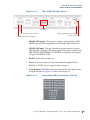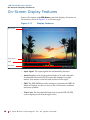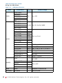
1
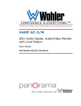
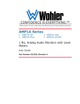
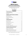
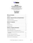
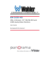
CONFIDENCE IS EVERYTHING.™
World Leader of In-Rack, Audio, Video, Data Monitoring, and Closed Captioning Solutions
RM-2435-HD
2RU, 4-Screen, 3.5” HD/SD-SDI and
CVBS Audio/Video Monitors
User Guide
Part Number 821711, Revision C
the video division of
© 2010 Wohler Technologies, Inc. and PANORAMA. All rights reserved.
This publication is protected by federal copyright law. No part of this publication may be
copied or distributed, stored in a retrieval system, or translated into any human or computer
language in any form or by any means electronic, mechanical, manual, magnetic, or otherwise,
or disclosed to third parties without the express written permission of Wohler Technologies.
Reproduction
Licensed users and authorized distributors of Wohler Technologies, Inc. products may copy
this document for use with Wohler Technologies., Inc. products provided that the copyright
notice above is included in all reproductions.
Customer Support
Wohler Technologies, Inc.
31055 Huntwood Avenue
Hayward, CA 94544
www.wohler.com
Phone: 510-870-0810
FAX: 510-870-0811
US Toll Free: 1-888-596-4537
(1-888-5-WOHLER)
Web: www.wohler.com
Sales: [email protected]
Support: [email protected]
Disclaimers
Even though Wohler Technologies, Inc. has tested its equipment and software, and reviewed
the documentation, Wohler Technologies, Inc makes no warranty or representation, either
express or implied, with respect to software, documentation, their quality, performance,
merchantability, or fitness for a particular purpose.
In no event will Wohler Technologies, Inc. be liable for direct, indirect, special, incidental, or
consequential damages resulting from any defect in the hardware, software, or its
documentation, even if advised of the possibility of such damages.
Some states do not allow the exclusion or limitation for incidental or consequential damages, so
the above exclusion or limitation may not apply to you.
Printing
This document is intended to be printed on a duplex printer, such that the copy appears on
both sides of each page. This ensures that all new chapters start on a right-facing page.
This document looks best when printed on a color printer since some images may be indistinct
when printed on a black and white printer.
Other Technologies and Products
Dolby is a registered trademark of Dolby Laboratories, Inc.
Microsoft Windows, and Internet Explorer are registered trademarks of Microsoft Corporation.
Last Update
May 17, 2010
ii
© 2 01 0 Wo h le r Te ch n ol og ie s , I n c . A l l r i g h t s r e s e rve d .
RM-2435-HD User Guide
Introduction
Overview
This 2U rack-mounted audio/video monitor sets a new standard in
LCD monitors for broadcast and professional video applications. The
RM-2435-HD has 640 x 480 resolution with anti-glare TFT screens, and
full digital signal processing support: HD-SDI and analog composite
video standards. All video formats are scaled to fit on screen in the
highest quality using full, digital processing, precision scaling, and
gamma correction to produce the best images available.
Topics
Topics
Introduction
Page
1
Safety Instructions
2
Front Panel Controls
6
Features
3
Specifications
5
Front Panel Controls
6
Rear Panel Connectors
8
On-Screen Display Features
10
Using the OSD Menu
11
Programming the Hot Key Buttons
13
Technical Functional Overview
15
© 2 01 0 Wo h le r Te ch n o l og ie s, I n c . A l l r i g h t s r e s e r v e d .
1
RM-2435-HD User Guide
S a f e t y I n s tr u c ti o n s
Safety Instructions
IMPORTANT:
1.
Read, keep, and follow all of these instructions; heed all warnings.
2.
Do not use this equipment near water.
3.
Use only a dry cloth to clean the equipment.
4.
Do not block any ventilation openings. Install only in accordance
with the instructions in the section entitled, “Front Panel Controls”
on page 6.
5.
Do not install near any heat source such as a radiator, heat register,
amplifier, or stove.
6.
Do not expose the equipment to rain or moisture.
7.
Do not attempt to plug the unit into a two-blade outlet (with only
two prongs of equal width).
By design, these audio/video monitors will only plug into a threeprong outlet for your safety. If the plug does not fit into your outlet,
contact an electrician to replace the obsolete outlet.
8.
Protect the power cord from being walked on or pinched,
particularly at plug’s source on the equipment and at the socket.
9.
Use only the attachments/accessories specified by the
manufacturer.
10. Unplug the equipment during lightning storms or when unused
for long periods of time.
11. Refer all servicing to qualified service personnel. Servicing will be
required under all of the following conditions:
2
•
The equipment has been damaged in any way, such as when
the power-supply cord or plug is damaged.
•
Liquid had been spilled or objects have fallen onto the
equipment.
•
The equipment has been exposed to rain or moisture.
•
The equipment does not operate normally.
•
The equipment has been dropped.
© 2 01 0 Wo h le r Te ch n ol og ie s , I n c . A l l r i g h t s r e s e rve d .
RM-2435-HD User Guide
I n s ta l la t i o n R e c o m me n d a t io n s
Installation Recommendations
Mounting
The unit is designed to install into a standard 19” rack. The unit should
be mounted at approximately ear level for optimum frequency
response and at eye level for optimum visual observation.
Heat Dissipation
No special physical mounting considerations are necessary regarding
heat dissipation except under adverse conditions, provided the
ambient temperature inside the mounting enclosure does not exceed
40°C (104°F). Adjacent devices can be rack mounted (or stacked) in
proximity to the unit. If the temperature is above 40°C, allow a 1RU
(1.75”/44.45mm) space above and below the unit for air circulation.
DC Power
Connect the unit to its external 100 to 240VAC (50 to 60Hz) to 12VDC
power supply (included).
Features
The RM-2435-HD audio/video monitor is designed for confidence
monitoring of HD/SD-SDI and composite video broadcast signal
(CVBS) video sources. Input signals are automatically detected and
accommodated. Up to eight of the sixteen audio channels embedded in
an HD/SD-SDI bit stream may be selected for visual monitoring on
eight on-screen bar graph style level meters. A Headphone Jack
provides audible stereo monitoring of the left/right channels.
Each of the four high-resolution LCD screens display high definition or
standard definition video at either 4:3 or 16:9 aspect ratio. Parameters
are selected and adjusted using an On Screen Display (OSD) MENU.
One function button may be programmed as a hot key for quick
© 2 01 0 Wo h le r Te ch n o l og ie s, I n c . A l l r i g h t s r e s e r v e d .
3
RM-2435-HD User Guide
Features
parameter settings. A DB9 connector serves as the interface to the four
tally lights on the front panel.
Additional overlays can be added by the operator for safe area and safe
title markers, center mark, time code, and display name. Time code is
derived from embedded HD/SD-SDI source.
The slim and light weight design provides four screens in a very
compact rack-size (2RU) while the chassis only has 2.2 inches of depth.
The feature-rich audio/video monitors provide all of the following:
• Four 3.5” LCDs
• Selectable 16:9 or 4:3 screen aspects for on screen video
• Rack mount mechanical design with vertical tilt
• Audio demux and display for up to eight channels from the sixteen
embedded in each HD/SDI-SDI source
• Monitoring of embedded audio through headphones
• Visually monitor audio levels on meters assignable to any channel
• Level meters can display VU, PPM (PK) or both with assignable
-22db to -18db level
• Local control (via menu operation) for all functions including:
4
•
Blue gun as mono
•
Safe area
•
Safe title
•
Center markers
•
H/V delay
•
Monochrome display mode
•
Over/underscan
•
Display of Input Signal format
© 2 01 0 Wo h le r Te ch n ol og ie s , I n c . A l l r i g h t s r e s e rve d .
RM-2435-HD User Guide
S p e ci f i c a t i o n s
•
Display of input time code and up to 10 characters of
user-defined text
•
Time Code and text position in top or bottom of screen
•
Red/green/yellow/white text color
•
Built in color bars 75% full field
•
User-defined configuration
•
Auto sets at power up
•
Waveform monitor
• User defined hot key functionality provides all of the following:
•
H/V delay toggle through functions
•
Underscan toggle on/off
•
On Screen Display (OSD) on/off
•
Color bar on/off
•
Audio monitor display on/off
•
Area marker toggle
Specifications
The specifications of the audio/video monitors are listed below.
Table 1–1
RM-2435-HD Specifications
Specification
Number of Screens
Display
Native Aspect Ratios
Viewing Angle (Tilt)
Screen Colors
RM-2435-HD
Domain Range
4
3.5” diagonal
4:3
100°H x 50°V
262,000
© 2 01 0 Wo h le r Te ch n o l og ie s, I n c . A l l r i g h t s r e s e r v e d .
5
RM-2435-HD User Guide
Front Panel Controls
Table 1–1
RM-2435-HD Specifications (Continued)
RM-2435-HD
Domain Range
Specification
Resolution (Dots, H x V)
Dot Pitch (H x V, mm)
Contrast Ratio
Pixel Response (ms)
Dimensions (W x Hmm)
Power Consumption
Operating Temperature
Video Format
Inputs
Outputs
Space Required
Supplied Accessories
Note:
640 x 480
0.1125 x 0.1095
350:1
<40 typical
19” x 3.5” x 2.2” (486 x 89 x 56 mm)
12VDC/10 Watts (3.8 Amps max)
CE & UL power supply
0°C (32°F) to 40°C (104°F)
NTSC/PAL auto recognition
HD/SD-SDI,
Analog Composite
(1 BNC per screen)
HD/SD-SDI Re-clocked output
(1 BNC per Screen)
2 rack units of an EIA-19 standard
equipment rack
AC power adapter
All of the specifications listed above are subject to change
without notice.
Front Panel Controls
The front panel feature descriptions refer to Figure 1–1 and Figure 1–2
below.
Figure 1–1
RM-2435-HD Front Panel
Tally Lights
6
© 2 01 0 Wo h le r Te ch n ol og ie s , I n c . A l l r i g h t s r e s e rve d .
RM-2435-HD User Guide
Front Panel Controls
• Tally Lights: These tri-color (red/green/amber) lights are
controlled through a DB9 connector on the rear of the panel. For
more information about the rear panel DB9 connector, refer to “Rear
Panel Connectors” on page 9..
Figure 1–2
RM-2435-HD Front Panel Menu
Headphone Jack
Mute
Power
Menu
Aspect
F1
Enter
Tally Light
Blue
LCD
• Headphone Jack: Monitor the assigned left/right stereo audio
channels with stereo headphones from this mini-stereo connector.
• Power: Each of the four Power buttons turn the associated LCD
screen on and off; the LED glows green to indicate on. When the
indicator above the power switch is green then the unit is receiving
power. When the indicator is flashing, the unit is in stand-by mode.
• Aspect: The Aspect button toggles the aspect ratio between 4:3
and 16:9 for the associated LCD screen. The LED glows green to
indicate 16:9.
© 2 01 0 Wo h le r Te ch n o l og ie s, I n c . A l l r i g h t s r e s e r v e d .
7
RM-2435-HD User Guide
R e a r P a n e l C o n n e ct o r s
• F1: The F1 button is programmable as a hot key for parameter
adjustments. Refer to “Programming the Hot Key Buttons” on page
13 for more information.
• Menu: Pressing the Menu button displays the OSD (On-Screen
Display) Menu. Refer to “Using the OSD Menu” on page 11 for
more information.
• Blue or ∧: When the OSD Menu is not active, pressing this button
toggles between three settings: blue monochromatic, grey scale
monochromatic, and full color. When the OSD Menu is active, this
button serves as the up (∧) navigation button in the menu.
• Mute or ∨: When the OSD Menu is not active, this button is used
to select the audio source for monitoring through the headphones.
Press this button on whichever LCD section you wish to audibly
monitor, and the green LED will light to indicate your selection.
Pressing it a second time will mute the audio. Subsequent presses
will toggle the mute off and on. The green LED flickers to indicate
the mute is on. When the OSD Menu is active, this button serves as
the down (∨) navigation button in the menu.
• Enter: When the OSD Menu is displayed, pressing this button
enters items and accepts selections in the OSD Menu. Otherwise, it
acts as a quick menu to select parameters for adjustment. Refer to
“Programming the Hot Key Buttons” on page 13 for more
information.
• LCD Screen: The LCD screens display the audio and video meters.
Rear Panel Connectors
The rear panel feature descriptions refer to the following image.
8
© 2 01 0 Wo h le r Te ch n ol og ie s , I n c . A l l r i g h t s r e s e rve d .
RM-2435-HD User Guide
Rear Panel Connectors
Figure 1–3
RM-2435-HD Rear Panel
RS-485
Tally Lights Interface Connector
Power Connector
HD/SD-SDI Input Connector
HD/SD-SDI Output Connector
• HD/SD-SDI Output: The system re-shapes and re-clocks an HD/
SD-SDI signal before outputting it to this female BNC connector.
• HD/SD-SDI Input: This auto-detecting, input connector accepts
HD/SD-SDI or analog CVBS video signals. The inputs comply with
SMPTE259M, SMPTE292M/ITU-R BT601. Composite video inputs
comply with SMPTE-170M.
• RS-485: Reserved for future use.
• Power: To provide power to the unit, attach the supplied 100 to
240VAC to 12VDC power supply to this connector.
• Tally Interface: This DB-9 connector controls the tally lights on the
front panel. Refer to Figure 1–4 below for the pin out.
Figure 1–4
Rear Panel DB-9 Connector Pin Out
© 2 01 0 Wo h le r Te ch n o l og ie s, I n c . A l l r i g h t s r e s e r v e d .
9
RM-2435-HD User Guide
On-Screen Display Features
On-Screen Display Features
Some of the buttons and OSD Menu control the display of features on
the screen as shown in Figure 1–5 on the next page.
Figure 1–5
Display Features
Input Signal
Audio Levels
IMD
Time Code
• Input Signal: The input signals are automatically detected.
• Audio Levels: Levels for the selected eight of 16 audio channels
de-embedded from an HD/SD source are displayed on eight
meters. Four meters on the left side and four on the right.
• IMD: The OSD MENU provides settings to customize the IMD (In
Monitor Display) text area to show a line of characters, numbers,
and some symbols.
• Time Code: The de-embedded time code from the HD/SD-SDI
source displays in the bottom right corner.
10
© 2 01 0 Wo h le r Te ch n ol og ie s , I n c . A l l r i g h t s r e s e rve d .
RM-2435-HD User Guide
Using the OSD Menu
Using the OSD Menu
A description of how to use the OSD Menu follows. Also refer to Table
1–2 below for typical values and domain ranges.
1.
Press the Menu button to display the menu.
Note:
2.
If you do not press another button for approximately 10
seconds, the menu will disappear from the screen.
Use the Up and Down buttons to navigate through the seven submenu icons. The sub-menus are:
A.
STATUS (No configurable options)
A.
VIDEO
B.
AUDIO
C.
MARKER
D.
OSD
E.
USER CONTROL
F.
USER CONFIG
3.
Press the Enter button to enter the chosen sub-menu.
4.
Use the Up or Down buttons to cycle through the sub-menu
selections.
5.
When the desired option is highlighted, press the Enter button to
select it.
6.
Use the Up or Down buttons to adjust the parameter value up or
down, make a selection, or turn a function on or off.
Press the Menu button to back out of a parameter or sub-menu. Press
the Menu button again to remove the menu from the screen.
© 2 01 0 Wo h le r Te ch n o l og ie s, I n c . A l l r i g h t s r e s e r v e d .
11
RM-2435-HD User Guide
U s i n g th e O S D M e n u
Table 1–2
OSD Menu Structure
Menu
Parameters
Default
Valuea
Domain Range
BRIGHTNESS
CONTRAST
VIDEO
SATURATION
128
0 to 255
VU+PK
VU, PK, VU+PK, NONE
SHARPNESS
HUE
MET 1 TYPE
MET 2 TYPE
MET 3 TYPE
MET 4 TYPE
AUDIO
MET 1-L SRC
CH 1
MET 1-R SRC
CH 2
MET 2-L SRC
CH 3
MET 2-R SRC
CH 4
MET 3-L SRC
CH 5
MET 3-R SRC
CH 6
MET 4-L SRC
CH 7
MET 4-R SRC
CH 8
TEST LEV
-20 db
-20DB to -18DB
HEADPHONE
ON
ON or OFF
AUDIO MON
MET 1
MET 1, MET 2, MET 3, or MET 4
VOLUME
-20dbfs
-30db to 0db
METER HPOS 1
METER HPOS 2
METER SIZE
AREA
MARKER
000
LARGE
CH 1 to CH 16
0 to 200
0 to 200
SMALL or LARGE
2.35:1, 1.85:1, 15:9, 14:9, 13:9,
4:3, OFF
SAFE MARKER
CENTER
90%
ON or OFF
80%
12
ZOOM
ZOOM
NORMAL or UNDERSCAN
H/V DELAY
H/V DELAY
H/V, V, H, OFF
© 2 01 0 Wo h le r Te ch n ol og ie s , I n c . A l l r i g h t s r e s e rve d .
RM-2435-HD User Guide
P r o g r a m m i n g t h e H o t K e y B u t to n s
Table 1–2
OSD Menu Structure (Continued)
Menu
Parameters
STD DISP
Default
Valuea
Domain Range
AUTO OFF, ON, or OFF
TC (Time Code) DISP
WFM (waveform
Monitor) DISP
ON or OFF
IMD (In Monitor
Display) DISP
STATUS
INDICATION
CONFIG
a
TOP or BOTTOM
(Note: This feature is disabled on
models that include the waveform
meter to avoid visual overlap.)
IMD POS
IMD COLOR
RED, GREEN, YELLOW, or WHITE
IMD:
A user-definable input string of up to
10 alphanumeric characters (also
includes some symbols)
DEFAULT
UNSET or SET
USER
H/V DELAY, UNDER SCAN, OSD
CONTROL, COLOR BAR, AUDIO
MON, AREA MARKER, or SAFE
MARKER
OSD CONTROL
ON or OFF
COLOR BAR
DISABLE
Only the V ID E O and AUD IO menus have default values.
Programming the Hot Key Buttons
The Enter Button
When the OSD Menu is not displayed, you can press the Enter button
to quickly adjust the following parameters:
1.
AUDIO MON: This option has four values, MET 1, MET 2, MET 3
and MET 4. Selecting MET 1 enables the first audio monitor.
Likewise, if you select another MET, the system will monitor the
corresponding audio source.
© 2 01 0 Wo h le r Te ch n o l og ie s, I n c . A l l r i g h t s r e s e r v e d .
13
RM-2435-HD User Guide
P ro g r a m mi n g t h e H o t K e y B u t t o n s
2.
VOLUME: This option regulates the volume from -30db to 0db.
3.
BRIGHTNESS: This option regulates the video brightness from
4.
CONTRAST: This option regulates the image contrast from -128 to
5.
SATURATION: This option regulates the color saturation of the
6.
SHARPNESS: This option regulates the sharpness of the image
7.
HUE: This option regulates the hue of the image from -32 to 31,
-116 to 139, where 0 is the typical value.
127, where 0 is the typical value.
image from -128 to 127, where 0 is the typical value.
from 0 to 15, where 0 is the typical value.
where 0 is the typical value.
Note:
By selecting the DEFAULT option in the CONFIG sub-menu,
you can reset the parameters of the BRIGHTNESS,
CONTRAST, SATURATION, SHARPNESS, and HUE options
to zero (0).
The User Button
You can use the User button as a hot key. Assigning a parameter to this
button allows that parameter to be displayed and adjusted on-screen at
the press of the button without displaying and navigating through the
OSD Menu.
To program the hot key:
1.
Press and hold the Menu button.
2.
Use the Up and Down buttons to find the CONFIG sub-menu and
press the Enter button to select it.
3.
Use the Up and Down buttons to cycle to the User selection and
press the Enter button to select it.
4.
Use the Up and Down buttons to select the following eight
parameters. Press the Menu button to exit the sub-menu. (Refer to
Table 1–2 starting on page 12 for the domain range for each of
these parameters.)
•
14
H/V DELAY
© 2 01 0 Wo h le r Te ch n ol og ie s , I n c . A l l r i g h t s r e s e rve d .
RM-2435-HD User Guide
T e c h n i c a l F u n c t i o n a l O v e r vi e w
•
UNDER SCAN
•
OSD CONTROL
•
COLOR BAR
•
AUDIO MON
•
AREA MARKER
•
SAFE MARKER
Technical Functional Overview
The following block diagram illustrates the overall functionality of the
RM-2435-HD.
© 2 01 0 Wo h le r Te ch n o l og ie s, I n c . A l l r i g h t s r e s e r v e d .
15
RM-2435-HD User Guide
Technical Functional Overview
Figure 1–6
16
RM-2435-HD Block Diagram
© 2 01 0 Wo h le r Te ch n ol og ie s , I n c . A l l r i g h t s r e s e rve d .