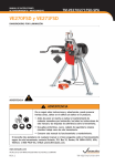
1
R
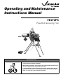
Operating and Maintenance
Instructions Manual
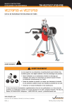
VE272FS
Pipe Roll Grooving Tool
WARNING
• Failure to follow instructions and warnings may result in serious personal injury,
property damage or improper installation.
• Before installing, operating, or servicing this tool, read and understand the instructions in this manual and all warning labels on the tool.
• If you need additional copies of the manual or have any questions about the safe
operation of this tool, contact Victaulic Europe, Prijkelstraat 36, Nazareth, Belgium,
phone: +32-9-381 15 00, or your Victaulic Sales Office.
VE272FS
READ THIS FIRST - HAZARD
IDENTIFICATION 4
OPERATOR SAFETY INSTRUCTIONS 4
General 4
Tool Setup 4
Operating Tool 5
Tool Maintenance 5
INTRODUCTION 6
Power Drive 6
Power Requirements 6
TOOL NOMENCLATURE 7
RECEIVING TOOL 8
Container Contents 8
TOOL SETUP 9
PRE-OPERATION ADJUSTMENTS 14
Grooving Rolls 14
Pipe Preparation 14
Groovable Pipe Lengths 14
Short Pipe Lengths 14
Long Pipe Lengths 15
Roll Guard Adjustment 16
Pipe Stabilizer Adjustment 18
Groove Diameter Stop Adjustment 20
ACCESSORIES 32
Victaulic Adjustable Pipe Stand VAPS112 32
Optional Rolls 32
Ridgid® 300 Power Drive 32
Pipe Stabilizer Assembly 32
TROUBLESHOOTING 34
TOOL RATING AND ROLL SELECTION 35
Standard and "ES" Rolls - Color Coded
Black 35
Rolls for Stainless Steel Pipe† (RX Rolls) - Color Coded Silver 36
Rolls for Copper Tubing - Color Coded
Copper† 36
ROLL GROOVE SPECIFICATIONS 37
Steel Pipe and All Materials Grooved with
Standard and RX Rolls 37
Drawn Copper Tubing 39
Steel Pipe and All Materials Grooved with
"ES" Rolls 40
PIPE DIMENSIONS 41
Seamless and Welded Steel Pipe† 41
Drawn Copper Tubing 41
GROOVING OPERATION 22
ROLL CHANGING 25
Roll Removal 25
Lower Roll (all sizes)
Upper Roll (all sizes)
Roll Installation 26
Upper Roll (all sizes)
Lower Roll (all sizes)
25
26
26
27
MAINTENANCE 28
General 28
Lubrication 28
Hydraulic Systems 29
Filling and Checking 29
Air Bleeding 30
Recommended Lubricants 30
Bearing and Slide Grease 30
Hydraulic Oil 30
PARTS ORDERING INFORMATION 31
3
VE272FS
READ THIS FIRST - HAZARD IDENTIFICATION
OPERATOR SAFETY INSTRUCTIONS
Definitions for identifying the various hazard
levels shown on warning labels or to indicate
proper safety procedures in this Manual are
provided below.
This tool is designed only for roll grooving pipe.
To accomplish this function requires some dexterity and mechanical skills, as well as sound
safety habits. Although this tool is manufactured for safe dependable operation, it is impossible to anticipate those combinations of
circumstances which could result in an accident. The following instructions are recommended for safe operation of the tool. The
operator is cautioned to always practice "Safety
First" during each phase of use, including setup
and maintenance of this unit. It is the responsibility of the owner, lessee or user of this
tool to ensure that all operators receive, read
and understand this manual and are fully
trained to operate this tool.
When you see these safety messages, be alert
to the possibility of personal injury or property
damage and carefully read and fully understand the instructions that follow.
DANGER
The use of the word "DANGER" always signifies an
immediate hazard with a likelihood of serious personal
injury or death if instructions, including recommended
precautions, are not followed.
General
WARNING
The use of the word "WARNING" signifies the presence
of hazards or unsafe practices which could result in serious personal injury or death if instructions, including
recommended precautions, are not followed.
CAUTION
The use of the word "CAUTION" signifies possible hazards or unsafe practices which could result in minor personal injury, product or property damage if instructions,
including precautions, are not followed.
• Read and understand this Manual before
operating or performing maintenance on
this tool. Become familiar with the tool’s operations, applications and limitations. Be particularly aware of its specific hazards. Store
this manual in a clean area and always at a
readily available location. Additional copies
at no charge are available upon request by
writing or phoning Victaulic Europe.
• Use only recommended accessories. Use
of improper accessories may be hazardous.
See "Accessories".
• This tool is designed ONLY for roll grooving of pipe sizes, materials and wall thicknesses outlined under "Tool Rating and
Roll Selection".
NOTICE
The use of the word "NOTICE" signifies special instructions which are important but not related to hazards.
4
Tool Setup
• Ground the drive motor. Be sure the drive
motor is connected to an internally grounded
electrical system.
VE272FS
• Avoid dangerous environments. Don't use
the machine in damp or wet locations. Don't
use the tool on sloped or uneven ground or
floor. Keep work area well illuminated. Allow
sufficient space to operate tool and accessories properly and for others to pass safely.
• Prevent back injury. During tool setup, it is
recommended to use a lift to move and position the tool, as it cannot be safely handled by
one person.
Operating Tool
• Inspect the equipment. Prior to starting the
tool, check the movable parts for any obstructions. Be sure that guards and tool parts
are properly installed and adjusted.
• Prevent accidental startings. Place power
switch in the "OFF" position prior to connecting electrical power.
• Operate tool from control station side only. The tool must be operated with the safety
foot switch control located for easy operator
access. Never reach across moving parts or
material being worked on. Foot switch should
always be accessible to operator.
• Keep hands away from grooving rolls and
stabilizer wheel during grooving operation. Grooving rolls can crush or cut fingers
and hands.
• Never reach inside pipe end or across the
tool or pipe during operation.
• Do not over-reach. Keep your proper footing
and balance at all times. Be sure you can
reach foot switch safely at all times. Do not
reach across tool or pipe. Keep hands and
loose tools away from moving parts.
• Always wear safety glasses and foot protection.
• Keep alert. Do not operate tool if ill or drowsy
from medication or fatigue. Avoid horseplay
around tool and keep bystanders a safe distance from tool and pipe being grooved.
• Wear proper apparel. Never wear loose
clothing (unbuttoned jackets or loose sleeve
cuffs) loose gloves or jewelry that can get
caught in moving parts.
• Do not force tool. It will do the job better and
safer at the rate for which it was designed.
• Secure work, machine and accessories.
Make sure machine is stable. See "Tool Setup" for securing machine to floor or platform.
• Support work. Support long pipe with a pipe
stand secured to the floor or ground.
• Do not misuse tool. Perform only the functions for which the tool is designed. Do not
overload the tool.
• Do not remove any labels from tool. Replace any damaged or worn labels.
Tool Maintenance
• Disconnect electrical power prior to servicing. Repair should be attempted only by
authorized personnel. Always disconnect
power before servicing or making any tool
adjustments unless instructed otherwise.
• Maintain tool in top condition. Keep tool
clean for best and safest performance. Follow lubricating instructions.
• Use only genuine Victaulic replacement
parts to ensure proper and safe function of
the tool.
NOTICE
Drawings and/or pictures in this manual may be exaggerated for clarity.
• Keep work area clean. Cluttered areas,
benches and slippery floors invite accidents.
• Wear ear protection if exposed to long periods of very noisy operations.
• Keep visitors away. All visitors should be
kept a safe distance from the work area.
5
VE272FS
INTRODUCTION
DANGER
®
®
The Victaulic Vic-Easy Series VE272FS is a
semi-automatic hydraulic feed tool for roll
grooving pipe to prepare it to receive Victaulic
grooved pipe couplings. It is designed to roll
groove pipe of various materials and wall thicknesses (see "Tool Rating and Roll Selection"
charts). An external power drive is required and
must be purchased separately.
Both this tool and the manual contain trademarks, copyrights and/or patented features
which are the exclusive property of Victaulic
Company of America.
CAUTION
• This tool should only be used for roll grooving pipe
designated in the "Tool Rating and Roll Selection"
charts.
• Use of the tool for other purposes or exceeding the
pipe thickness maximums will overload the tool,
shorten tool life and may cause tool damage.
Power Drive
This tool is designed for power operation. Tools
mount directly onto a Ridgid® 300* Power Drive
(45 rpm maximum chuck speed) or a Victaulic
VPD752/753 power drive. Consult drive manufacturer’s instructions for proper operation.
* Ridgid is a registered trademark of Ridge Tool Company.
Power Requirements
Power must be supplied through a safety foot
switch to ensure safe operation. Be sure the
tool is properly grounded in accordance with
local regulations.
CAUTION
• Power supplied to the tool must be 230 V ±5%.
• Failure to do so may result in shortened tool life and
property damage.
6
• To reduce the risk of electric
shock, check the electrical source
for proper grounding.
• Always disconnect power before
servicing or making any tool
adjustments unless instructed
otherwise.
• Failure to do so may result in serious personal injury.
VE272FS
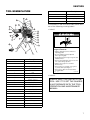
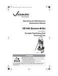
TOOL NOMENCLATURE
1
i
h
3
Item
j
k
l
g
n
e
stabilizer roller
v
power drive stand
w
upper leg
x
adjusting legs
The numbers in the illustration indicate the location of the following warning labels:
m
f
Description
u
o
• Label 1
p
q
r
d
s
2
b
c
t
u
a
v
w
Grooving rolls can crush or cut
fingers and hands.
x
Item
Description
a
foot switch
b
lower roll
c
guard setting pad
d
pump support
e
pump handle
f
pump
• Always unplug the power cord before
adjusting guard.
• Be sure guard is properly adjusted
before grooving pipe.
• Keep hands away from grooving rolls and
stabilizer wheel.
• Never reach inside pipe end or across the
tool or pipe during operation.
• Always groove pipe in a clockwise
direction only.
• Never wear loose clothing, loose gloves
or jewelry while operating tool.
• Never groove pipe shorter than what is
recommended.
0585
g
pump valve
h
hydraulic cylinder
i
hydraulic connectors
j
pipe size indicator
k
depth adjuster
l
depth adjuster lock
m
upper roll assembly
n
upper roll bolt
o
roll guards
p
power drive
q
lifting handles
r
power drive support arms
s
stabilizer assembly (optional)
t
stabilizer hand wheel
9/94
R033272LAB
• Label 2
ALWAYS KEEP THIS PAD WITH THE
TOOL. USE IT TO SET THE GUARDS
IN ACCORDANCE WITH THE TOOL
OPERATION AND MAINTENANCE
MANUAL.
7
VE272FS
RECEIVING TOOL
• Label 3
Failure to follow instructions and warnings can result in
serious injury, property damage, or faulty installation.
• Before installing, operating, or servicing this tool, read and
understand the Operating Instructions and all warning
labels on this tool.
Victaulic® VE272FS tools are packed individually in sturdy containers, designed for use in reshipping the tool.
• Always wear safety glasses and foot protection.
If you have any questions about the safe operation of this tool,
contact Victaulic Tool Company, P.O. Box 31, Easton, PA 18044-0031,
610-559-3300.
0567 Rev.A
R031272LAB
3/99
NOTE: Be sure to save original shipping materials for return shipment of rental tools.
Upon receipt of tool, make sure all necessary
parts are included. If any parts are missing, notify your Victaulic distributor or Victaulic representative.
Container Contents
• Tool head assembly with a base for Ridgid®
300 or Victaulic VPD752 power drive
• Telescoping leg assembly
• Pump/pump support assembly
• Rolls for 60,3 - 168,3 mm and 219,1 - 323,9
mm steel pipe. The 219,1 - 323,9 mm rolls are
mounted on the head assembly.
• Two (2) tool operating manuals
• Guard setting pad
• Lower roller removal wedge
• Stabilizer with mounting hardware, if ordered
• Spare Woodruff keys
• One (1) 0,325 l can of Dow Corning G-n Mechanical Assembly Spray
The standard series VE272FS tools are supplied with grooving rolls for 60,3 - 323,9 mm
8
VE272FS
carbon steel pipe. Rolls are marked with the
size and part number and color coded for pipe
material, for your convenience.
For grooving to other specifications and other
materials, see "Tool Rating and Roll Selection"
charts. Grooving rolls for other specifications
and other materials must be purchased separately.
TOOL SETUP
WARNING
• Do not connect power until instructed otherwise.
• Accidental start up of tool may result in serious personal injury.
This tool is intended for field or shop setup. Before grooving, the tool head assembly and legs
must be mounted on a Victaulic VPD752 power
drive or a Ridgid 300 power drive.
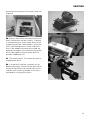
1 Remove all components from the containers and check to be certain all necessary items
are included. See "Receiving Tool."
2 Locate the tool on a level concrete floor or
base. A suitable location provides:
• the required power as described under "Power Requirements"
• the required space for adequate handling of
pipe to be grooved
• a level and even surface for tool, pipe stand
and footing
3 Prepare the power drive to receive the tool.
Remove threading dies, cut off attachments,
etc., from the power drive.
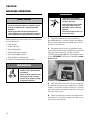
4 Extend the two (2) tubular support arms approximately 20 cm beyond the power drive
chuck. Secure the support arms in this position.
(Consult power drive manufacturer's instructions.)
9
VE272FS
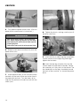
5 Fully open the power drive chuck. (Consult
power drive manufacturer's instructions.)
WARNING
8 Tighten the chuck, making sure the jaws fit
the drive shaft flats.
• While the tool head assembly is on the power drive
arms, without support legs installed, it is front heavy.
Have someone push back on the tool head to prevent
it from tipping over.
• Failure to do so may result in serious personal injury.
6 Slide the tool head assembly fully onto the
power drive arms.
9 Insert the two (2) adjusting legs completely
into the sockets of the upper leg and finger
tighten the hex bolts.
10 Insert the top leg assembly fully into the
socket under the tool head assembly. Rotate
the assembly so it fully seats in the socket. The
hex head bolts on the legs should be toward
the back of the machine, i.e. toward the power
drive.
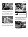
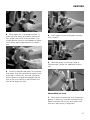
7 Allow approximately 15 mm clearance from
hex bolts on the back of the tool to the face of
the power drive chuck. Turn the lower roll to
align the flat portions of the drive shaft with the
chuck jaws.
10
VE272FS
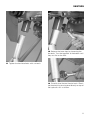
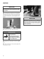
12 Release the lower legs by loosening the
hex bolts. Turn the leg pads at the bottom until
they rest flat on the floor.
11 Tighten the hex head bolts with a wrench.
13 Carefully level the tool front to back. Check
tool levelness by placing level directly on top of
the hydraulic ram as shown.
11
VE272FS
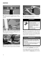
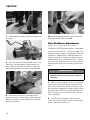
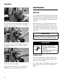
14 Tighten the hex head bolts with a wrench.
The legs should now support the tool in a level
position.
17 Hang the guard setting pad on the hook
provided under the pump base.
DANGER
• To reduce the risk of electric
shock, check the electrical source
for proper grounding.
• Always disconnect power before
servicing or making any tool
adjustments unless instructed
otherwise.
• Failure to do so may result in serious personal injury.
15 Attach the pump and its support to the left
side of the tool, using the two (2) hex bolts supplied. Tighten with a wrench.
18 Make sure the power drive is OFF. (Consult
power drive manufacturer's instructions.) Connect the power drive to an internally grounded
electrical outlet. The outlet must meet the power
requirements for the power drive.
WARNING
• The power drive must be operated with a safety foot
switch for safe tool operation. If your power drive
does not have a foot switch, contact the power drive
manufacturer.
• Failure to follow instructions and warnings may result
in serious personal injury, property damage or
improper installation.
16 Connect the hydraulic line from the pump to
the power cylinder using connectors provided.
12
19 Turn the power drive switch to the position
that will produce clockwise rotation of the
chuck when viewed from the front of the tool.
On the Ridgid 300 and Victaulic VPD752, putting the switch in the Reverse position will pro-
VE272FS
duce clockwise rotation of the chuck, lower roll
and pipe.
20 Depress foot switch and check chuck and
lower roll direction and tool stability. If rotation
is counterclockwise, move power drive switch
to opposite position. If tool wobbles, make sure
tool is mounted squarely in chuck and tool is
level. If the wobble cannot be eliminated, the
power drive support arms are bent or the power
drive is damaged. Have the power drive repaired if wobble persists.
21 Disconnect power. Turn power drive off or
unplug power drive.
22 If an optional stabilizer assembly was ordered (separately), attach it to the right side of
the tool using the four hex socket cap screws
and four lock washers provided. A hex key is
provided for installing the screws.
13
VE272FS
PRE-OPERATION ADJUSTMENTS
CAUTION
®
Every Victaulic tool is checked, adjusted and
tested at the factory prior to shipment. Before
grooving, however, the following adjustments
must be made in sequence to make sure of
proper tool operation.
• For maximum grooving roll life, remove foreign material and loose rust.
• Foreign material such as coarse scale or dirt might
interfere with or damage the grooving rolls or distort
the groove. Rust is an abrasive material and will tend
to wear out the surface of the grooving rolls.
WARNING
• Always disconnect power before servicing or making
any tool adjustments unless instructed otherwise.
• Accidental start up of tool may result in serious personal injury.
Victaulic recommends that pipe shall be
square ended. When using beveled pipe, standard wall or less, the bevel should not exceed
37,5°. Square ended pipe must be used with
FlushSeal® and EndSeal® gaskets. For heavier
pipe walls, square ended pipe is also required.
Grooving Rolls
Groovable Pipe Lengths
Make sure the proper roll set is on the tool for
the pipe size and material to be grooved. Rolls
are marked with the pipe size, part number and
color coded for the pipe material to be grooved.
See "Tool Rating and Roll Selection" charts. If
proper rolls are not on tool, refer to "Roll Changing".
The VE272FS is capable of grooving short pipe
lengths without the use of a pipe stand (see Table 1), or long pipe lengths up to double randoms (approximately 12,2 m.) with the use of
appropriate pipe stands.
Short Pipe Lengths
CAUTION
• Make sure roll retaining bolts and set screws are tight.
• Loose retaining bolts or set screws could seriously
damage both the tool and rolls.
Pipe Preparation
For proper tool operation, and production of
proper pipe grooves, carefully observe the following pipe preparation tips.
• Pipe ends should be cut squarely in accordance with Column 1 note in the appropriate
chart under "Roll Groove Specifications".
• Internal or external weld bead or seams must
be ground flush with the pipe surface extending 51 mm back from the pipe end.
• The end of the pipe, both inside and out, must
be cleaned of loose rust, coarse scale, dirt
and other foreign material.
14
Table 1 shows minimum and maximum pipe
lengths that can be grooved without the need
for a pipe stand. Refer to "Grooving Operation"
for instructions on how to groove short pipe
lengths. For pipe longer than shown in Table 1,
refer to "Long Pipe Lengths".
WARNING
• Grooving rolls can crush or cut
fingers and hands.
• Loading and unloading pipe will
place your hands close to the rollers.
• Never groove pipe shorter than
what is recommended (See
"Groovable Pipe Lengths").
Table 1 - Pipe lengths groovable without a pipe stand
VE272FS
stead of roll grooving a 6.000 mm piece of pipe
and a 198 mm piece of pipe, follow these steps:
Length – [mm]
O.D.
[mm]
Min.
Max.
60,3
203
914
73,0
203
914
88,9
203
914
101,6
203
914
114,3
203
914
127,0
203
813
141,3
203
813
152,4
254
762
168,3
254
711
203,2
254
610
219,1
254
610
273,0
254
508/381 *
323,9
305
457/356 †
* 508 mm long for aluminum, PVC and lightwall steel and stainless steel.
381 mm long for Sched. 30 and standard wall steel and stainless steel.
† 457 mm long for aluminum, PVC and lightwall steel and stainless steel.
356 mm long for Sched. 30 and standard wall steel and stainless steel.
If a pipe shorter than the minimum shown in Table 1 is needed, if possible, shorten the next to
last piece of pipe enough so that the last piece
of pipe is as long or longer than the minimum
length specified in Table 1. See example below.
1 Refer to Table 1 and note that for 273,0 mm
diameter pipe, the minimum length that should
be grooved is 508 mm
2 Roll groove a 5.690 mm piece of pipe and
a 508 mm piece of pipe. Refer to "Long Pipe
Lengths" below.
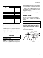
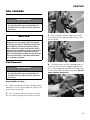
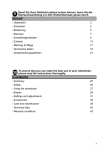
Long Pipe Lengths
With pipe in excess of the maximum length
shown in Table 1, a roller type pipe stand must
be used.
NOTICE
The figures below show the Victaulic adjustable pipe
stand (VAPS 112). VAPS 112 is suitable for 26,9 - 323,9
mm pipe. Also available is Victaulic model VAPS 224
suitable for sizes 60,3 - 610,0 mm. See "Accessories".
1 Position pipe and pipe stand in accordance with the figures below.
Pipe angle
exaggerated for clarity
Tool
Centerline
(Level)
¹⁄₂° to 1°
(50,8 to 101,6 mm)
NOTICE
Pipe
Centerline
Pipe nipples shorter than those shown in the table above
are available from Victaulic.
Example: A 6.198 mm length of 273,0 mm diameter pipe is needed to finish a section and
you only have 6.000 mm lengths available. In-
3m
+0,3 m -0
6 m Pipe
Figure 1 - Support of pipe
15
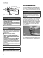
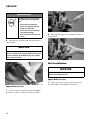
VE272FS
Tool Centerline
Pipe angle
exaggerated for clarity
0° to ¹⁄₂° Max.
(0 to 50,8 mm)
Pipe Centerline
6 m Pipe
Figure 2 - Tracking angle
WARNING
• Pipe stand location will affect pipe tracking.
• Incorrect pipe stand position may cause the pipe to be
pushed out of rolls and fall.
• Failure to position pipe and pipe stand in accordance
with the figures shown may result in serious personal
injury or property damage.
Roll Guard Adjustment
The VE272FS guards must be adjusted every
time rolls are changed or pipe size or wall thickness is different from pipe previously grooved.
WARNING
• Always disconnect power before servicing or making
any tool adjustments unless instructed otherwise.
• Accidental start up of tool may result in serious personal injury.
1 Make sure the proper roll set is on the tool
for the pipe size and material to be grooved.
Rolls are marked with the pipe size, part number and color coded for the pipe material to be
grooved. See "Tool Rating and Roll Selection"
charts. If proper rolls are not on tool, refer to
"Roll Changing".
CAUTION
Pipe position will affect pipe flare.
• When pipe end flare is excessive, right-to-left tracking
must be kept to a minimum. It may be necessary to
use less than 0,5°.
Make sure tool is level (see "Tool Setup").
• If pipe is grooved with back end of pipe (end of pipe
which is not in tool) higher than the end being
grooved, pipe may not track and excessive pipe end
flare may result.
• Assembly of couplings on pipe exceeding Maximum
Allowable Flare (see "Roll Groove Specifications"
charts) may prevent closure of couplings pad-to-pad,
allowing possible pipe separation, and result in property damage.
• Also, joint leakage may result due to excessive gasket
distortion/damage.
NOTICE
For additional information about pipe stands, refer to the
Operating Instructions included with your pipe stand.
16
2 Loosen wing nuts and move the adjustable
guards to the full up position. Tighten wing nuts.
VE272FS
3 Set groove diameter stop to pipe size and
schedule/thickness to be grooved. To do this,
back off the depth adjuster lock, align the depth
adjuster with the proper diameter and thickness. Lock the depth adjuster in position with
the depth adjuster lock. See "Groovable Pipe
Lengths" instructions and cautionary information.
WARNING
• Grooving rolls can crush or cut
fingers and hands.
• Loading and unloading pipe will
place your hands close to the rollers.
• Never groove pipe shorter than
what is recommended (See
"Groovable Pipe Lengths").
5 Insert a piece of pipe of the correct size
and schedule/thickness to be grooved over the
lower roll with the pipe end against the lower roll
backstop flange. See "Pipe Preparation".
4 If so equipped, retract stabilizer, if necessary, to insert pipe. To do this, loosen the stabilizer locking handle and retract stabilizer roller
with the hand wheel to clear pipe when inserted
onto lower roll.
6
Close hand pump valve.
17
VE272FS
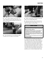
7 Pump upper roll down into firm contact with
the pipe.
10 Remove the guard setting pad. Store the
pad back on the hook provided.
Pipe Stabilizer Adjustment
(applies only to tools equipped with the optional stabilizer)
8 Remove the guard setting pad from its storage hook. Hold the guard setting pad firmly
down against the pipe and push it under the
adjustable guards flush against the red plate.
The Series VE272FS pipe stabilizer is designed
to pervent sway of 219,1 - 323,9 mm pipe. This
applies to short as well as long pipes. Once the
stabilizer is adjusted for a selected pipe size
and wall thickness, it does not require further
adjustment on that size and thickness. Pipe of
the same size and thickness may be moved in
and out of the tool without retracting the stabilizer.
WARNING
• Do not connect power until instructed otherwise.
• Accidental start up of tool may result in serious personal injury.
9 Loosen the wing nuts and adjust each
guard to conform to and lightly pinch the pad
against the pipe. Tighten wing nuts to secure
guards in position.
18
1 Make sure the proper roll set is on the tool
for the pipe size and material to be grooved.
Rolls are marked with the pipe size, part number and color coded for the pipe material to be
grooved. See "Tool Rating and Roll Selection"
charts. If proper rolls are not on tool, refer to
"Roll Changing".
2 Loosen locking handle. With the hand
wheel, retract the stabilizer roller to clear pipe
when inserted onto lower roll.
VE272FS
3 Insert a piece of pipe of the correct size
and schedule/thickness to be grooved over the
lower roll with the pipe end against the lower roll
backstop flange.
5 Make sure guards are properly adjusted.
Refer to "Roll Guard Adjustment".
6 Advance stabilizer roller inward with the
handwheel until the roller lightly contacts the
pipe, then tighten locking handle.
CAUTION
4 Close hand pump valve and pump upper
roll down into firm contact with the pipe.
Do not adjust stabilizers to push pipe to the left and off
center from the rolls. Doing so will cause increased pipe
end flare and shorten roller life.
• Assembly of couplings on pipe exceeding Maximum
Allowable Flare (see "Roll Groove Specifications"
charts) may prevent closure of couplings pad-to-pad,
allowing possible pipe separation, and result in property damage.
• Also, joint leakage may result due to excessive gasket
distortion/damage.
7 Complete the "Pre-Operation Adjustments"
and groove the pipe (see "Grooving Operation".) Observe the stabilizer roller while grooving. It should remain in contact with the pipe
most of the time and the pipe should rotate
smoothly without swaying from side to side. If
not, advance stabilizer roller further inward. Retest and make further adjustments as necessary. Remember, do not adjust stabilizer too far
inward as it will skew the pipe to the left and
possibly result in excessive pipe end flaring.
19
VE272FS
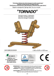
For your convenience, a "C" dimension chart for
steel pipe is also on the tool.
NOTICE
To perform the following adjustments, use several short
scrap sections of pipe (but not shorter than what is recommended in the "Groovable Pipe Lengths" table) of the
proper material, diameter and thickness to be grooved.
To achieve proper diameter:
1 Determine the size and thickness of pipe to
be grooved. See "Pipe Dimensions" to determine proper schedule.
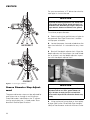
INCORRECT
2 Locate the proper size and schedule on the
pipe size indicator. It is rotatable for easy viewing.
3 Back off the depth adjuster lock. Align the
depth adjuster with the proper size and schedule as shown. Lock the depth adjuster in position with the depth adjuster lock.
CORRECT
Figure 3 - Positioning the stabilizer.
Groove Diameter Stop Adjustment
The groove diameter stop must be adjusted for
each pipe size or change in wall thickness.
Groove diameter, identified as the "C" dimension for each pipe size, is listed under "Standard Roll Groove Specifications".
20
NOTICE
The markings provide an approximate groove diameter
adjustment and are not "exact" groove diameter settings. Variations in actual pipe O.D.’s and wall thicknesses make it impossible to calibrate the diameter stop
exactly.
4 Using a piece of scrap pipe or short piece
of pipe (refer to the "Groovable Pipe Lengths"
table) of the diameter and wall thickness to be
VE272FS
grooved, place the pipe over the lower roll with
the pipe end against the lower roll backstop
flange.
the groove. Average reading must equal the required groove diameter specification.
WARNING
CAUTION
• Grooving rolls can crush or cut
fingers and hands.
• Always disconnect power before
servicing or making any tool
adjustments unless instructed
otherwise.
• Be sure guard is properly
adjusted before grooving pipe.
• Keep hands away from grooving
rolls and stabilizer wheel.
• Never reach inside pipe end or
across the tool or pipe during
operation.
• Never groove pipe shorter than
what is recommended (See
"Groovable Pipe Lengths").
• Never wear loose clothing, loose
gloves, or jewelry while operating
tool.
5 Prepare a trial groove. To do so, follow the
"Grooving Operation" procedures.
• The "C" dimension (groove diameter) must always
conform to specifications under "Roll Groove Specifications" to ensure proper joint performance.
• Failure to follow instructions and warnings may result
in serious personal injury, property damage or
improper installation.
7 If groove diameter ("C" dimension) is not
within tolerance, the diameter stop must be adjusted to obtain the proper dimension. To adjust
for a smaller groove diameter, turn the depth
adjuster counterclockwise. To adjust for a
bigger groove diameter, turn adjuster clockwise. A quarter turn either way will change the
groove diameter adjustment by 0,79 mm (3,175
mm per full turn).
8 Prepare another trial groove and check the
groove diameter again. Repeat the two previous steps until the groove diameter is within
specification.
6 After a trial groove is prepared and pipe removed from the tool, carefully check the groove
diameter ("C" dimension), as charted under
"Roll Groove Specifications". The "C" dimension
is best checked with a pipe tape. It also may be
checked with a vernier caliper or narrow-land
micrometer at two locations, 90° apart, around
21
VE272FS
GROOVING OPERATION
DANGER
CAUTION
• Victaulic® Series VE272FS tools are designed ONLY
for roll grooving pipe of the sizes, materials and wall
thicknesses outlined under "Tool Rating and Roll
Selection".
• Grooving pipe other than that recommended will
result in improper pipe end configuration or improper
groove dimensions for applying Victaulic products.
Before grooving, make sure you have followed
all instructions in:
• "Tool Setup"
• "Grooving Rolls"
• "Pipe Preparation"
• "Groovable Pipe Lengths"
• "Roll Guard Adjustment"
• "Pipe Stabilizer Adjustment"
• To reduce the risk of electric
shock, check the electrical source
for proper grounding.
• Always disconnect power before
servicing or making any tool
adjustments unless instructed
otherwise.
• Failure to do so may result in serious personal injury.
1 Plug the power drive into an internally
grounded electrical source. Make sure power
drive is grounded. Consult power drive manufacturer’s instructions.
2 Set power drive switch to produce clockwise rotation of lower roll and pipe when viewed
from the front of the tool. On the Victaulic
VPD752/753 and Ridgid 300, putting the switch
in the "REVERSE" position will produce clockwise rotation.
• "Groove Diameter Stop Adjustment"
WARNING
• Before operating tool, review precautions under "Operator Safety
Instructions".
• Failure to follow instructions and
warnings may result in serious
personal injury, property damage
or improper installation.
3 Actuate safety foot switch by pressing foot
on pedal to be certain tool is operational, power
supply is available, and that lower roll is turning
clockwise when viewed from the front. Remove
foot from foot switch.
4 Open hand pump valve by turning counterclockwise. This will allow upper roll and arm to
move to full up position.
22
VE272FS
WARNING
• Grooving rolls can crush or cut
fingers and hands.
• Always disconnect power before
servicing or making any tool
adjustments unless instructed
otherwise.
• Always groove pipe in a clockwise
direction only.
• Be sure guard is properly
adjusted before grooving pipe.
• Keep hands away from grooving
rolls and stabilizer wheel.
• Never reach inside pipe end or
across the tool or pipe during
operation.
• Never groove pipe shorter than
what is recommended (See
"Groovable Pipe Lengths").
• Never wear loose clothing, loose
gloves, or jewelry while operating
tool.
6 Close hand pump valve by turning clockwise.
7 Pump the handle several times to bring the
upper roll into light but firm contact with the
pipe.
5 Insert a piece of pipe of the correct size
and schedule/thickness to be grooved over the
lower roll with the pipe end against the lower roll
backstop flange.
8 If grooving a short pipe (see "Groovable
Pipe Lengths"), remove hands from pipe.
9 Depress and hold down safety foot switch.
The pipe will begin to rotate clockwise. As the
pipe rotates, begin grooving by slowly pumping the pump handle.
23
VE272FS
NOTICE
Do not pump too fast, but at a rate sufficient to groove
the pipe and maintain audible moderate-to-heavy load on
the gear motor.
10 Let the grooving continue until the depth
adjuster lock comes into full, firm contact with
the underlying surface. Continue pipe rotation
for several revolutions to ensure groove completion.
NOTICE
Groove diameter should be correct for the diameter and
wall thickness of pipe for which it was set under "Groove
Diameter Stop Adjustment". Groove diameter should be
checked and adjusted as necessary to ensure grooves
are within specification.
11 Withdraw foot from safety foot switch.
WARNING
• Grooving rolls can crush or cut
fingers and hands.
• Do not place hand(s) inside end of
pipe to pull pipe out of tool or
place hand(s) in area of grooving
rolls or stabilizer roller.
12 If grooving a short pipe, manually support
pipe.
13 Open hand pump valve to release pipe. Remove pipe from tool.
24
VE272FS
ROLL CHANGING
WARNING
• Always disconnect power before servicing or making
any tool adjustments unless instructed otherwise.
• Accidental start up of tool may result in serious personal injury.
NOTICE
Victaulic® Series VE272FS roll grooving tools are
designed for fast, easy grooving. Rolls accommodate
several pipe sizes (refer to "Tool Rating and Roll Selection") eliminating the need for frequent roll changes.
When a different size range is encountered or special
grooving styles are required, the grooving rolls must be
changed and Pre-Operation Adjustments performed
again. Also, different pipe materials may require that the
rolls be changed. Refer to "Tool Rating and Roll Selection" for proper roll selection.
3 With a wrench, loosen large nut on lower
shaft and back off approximately 6,5 mm without removing.
Roll Removal
WARNING
• Always disconnect power before servicing or making
any tool adjustments unless instructed otherwise.
• Accidental start up of tool may result in serious personal injury.
4 To loosen lower roll from tapered lower roll
shaft, use the aluminum wedge supplied with
tool. Place wedge behind lower roll and hit with
a hammer to break roll loose from taper. Do not
use a hammer on the roll.
Lower Roll (all sizes)
1 Open hand pump valve by turning counterclockwise. This will allow upper roll and arm to
move to full up position.
2 With a wrench, loosen and remove (thin)
jam nut securing large nut on lower roll shaft.
25
VE272FS
WARNING
Hammering rolls can cause serious
personal injury due to fragmentation.
• Always wear eye protection.
• Always use supplied aluminum
wedge for roll removal.
• Always use soft faced hammers
with aluminum wedge.
• Never strike rolls directly for any
reason.
2 Remove the upper roll assembly. Store in a
clean place.
5 Remove nut, washer and roll and store in a
clean place.
NOTICE
Be careful not to lose the Woodruff keys. They should
remain in the lower shaft. Inspect the Woodruff keys and
replace if damaged. Spare Woodruff keys are supplied
with instruction manual.
Roll Installation
NOTICE
See "Tool Rating and Roll Selection" charts for information on available grooving rolls.
Upper Roll (all sizes)
1 Clean all shaft surfaces and roll bores of
any dirt and/or scale before installation.
Upper Roll (all sizes)
1 With a wrench, loosen and remove upper
roll bolt as shown. Place on a clean surface.
26
VE272FS
2 While upper roll is removed from tool, inspect the roller bearing inside for contamination, proper lubrication and movement. Also
inspect guards for wear and freedom of adjustment. Make repairs/replacements as necessary.
4 Insert upper roll bolt and tighten securely
with a wrench.
5 Lubricate upper roll bearing. Refer to
"Maintenance" section for additional information.
3 Carefully slide desired upper roll assembly
onto upper shaft with red plate facing out. Loosen guards, if necessary, to make installation
easier. Make sure red plate engages the two
pins on the arm and that it then contacts the
front of the upper roll shaft.
Lower Roll (all sizes)
1 Place lower roll onto arbor shaft. Reposition
guards, if necessary, to make assembly easier.
Make sure lower roll fits fully onto arbor shaft
with keys and keyway in alignment.
27
VE272FS
MAINTENANCE
General
This manual provides information to permit the
operator of Victaulic® roll grooving tools to keep
his equipment in top operating condition and to
guide him in making repairs when it becomes
necessary.
2 Install flat washer and large nut on threaded arbor stud, in front of lower roll, and tighten
securely with a wrench.
Replacement parts, applicable only to these
tools, should be ordered from Victaulic to ensure proper operation of the tool. All parts are
supplied ex Nazareth, Belgium – unless otherwise stated – at the price in effect at the time of
ordering.
NOTICE
Remember that preventative maintenance during operation will pay for itself in repair and operating savings.
DANGER
3 Install (thin) jam nut on threaded arbor stud
and tighten securely, with a wrench, against
large nut.
• Always disconnect power before
servicing or making any tool
adjustments unless instructed
otherwise.
• Failure to do so may result in serious personal injury.
Lubrication
After every eight hours of operation lubricate
the tool. Always lubricate upper roll bearings
when rolls are changed.
Roll installation is complete.
Before grooving, make sure all "Pre-Operation
Adjustments" are reviewed and followed.
28
1 Grease upper roll bearing at fitting provided as shown. Use a No. 2EP Lithium base
grease.
VE272FS
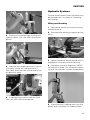
Hydraulic Systems
The level of the hydraulic fluid in the pump must
be checked every six months or if pumping
feels spongy.
Filling and Checking
1 Open pump release valve fully by turning
counterclockwise.
2 Grease main shaft bearings at fittings provided as shown. Use a No. 2EP Lithium base
grease.
2 Remove pump and pump support from tool
base.
3 Loosen, but do not remove the hydraulic fill
plug/dipstick at the back end of the pump.
3 Lubricate the linkage mechanisms, the arm
pivot point and the arm sliding surfaces. A
heavy duty spray lubricant may be used, or apply grease by hand.
4 Hold pump so that fill plug end is ABOVE
the hydraulic cylinder. This will prevent siphoning of oil from hydraulic cylinder through pump.
4 If mounted, lubricate the stabilizer wheel
with a No. 2EP Lithium base grease.
5 Check fluid level. Add hydraulic jack oil to
proper level as required. On models without
29
VE272FS
dipstick, remove cap; oil should be approximately 15-25 mm from the end.
Air Bleeding
1 To bleed air from the system, hold the entire
pump above the hydraulic cylinder. Close the
pump release valve by turning clockwise. Open
fill plug one full turn.
Recommended Lubricants
Bearing and Slide Grease
General Purpose E.P. Lithium Base Grease.
2 Pump the pump handle several strokes to
build pressure.
3 Open release valve by turning counterclockwise and allow air to escape.
4 Repeat steps 1 - 3 several times to bleed all
the air from the system.
5
Check oil level and add oil if necessary.
6 Continue to hold the pump above the hydraulic cylinder and close the fill plug.
7 Install the pump and pump support assembly securely to the side of the tool.
30
Manufacturer
Product
Amoco Oil
Amolith Grease #2EP
Arco Petroleum Prod. Co.
Litholine HEP 2
Ashland Oil, Inc./Valvoline Oil Co.
Multi-Lube Lith. EP Grease
Exxon Co., USA
Lidok EP 2
Gulf Oil Corp.
Gulfcrown Grease EP#2
Kendall Refining Co.
L-426
Lubriplate
No. 630-2
Mobil Oil Corp.
Mobilux EP2
Pennzoil Prod. Co.
Pennlith EP 712 Lube
Shell Oil Co.
Alvania EP2
Sun Refining
Sun Prestige 742 EP
Texaco Inc.
Multifak EP2
Hydraulic Oil
High Pressure Anti-Wear Hydraulic Oil ISO
Grade 32.
Manufacturer
Product
Amoco Oil
Rykon Oil #32
Arco Petroleum Prod. Co.
Duro AW 32
Ashland Oil, Inc./Valvoline Oil Co.
AW Oil #15
Exxon Co., USA
Nuto H 32
Gulf Oil Corp.
Harmony 32 AW
Kendall Refining Co.
Kenoil R&O AW-32
Lubriplate
HO-O
VE272FS
Manufacturer
Product
Mobil Oil Corp.
Mobil DTE 24
Pennzoil Prod. Co.
AW 32 Hyd. Oil/Penreco Oil 32
Shell Oil Co.
Tellus 32
Sun Refining
Survis 706, 816 WR
Texaco Inc.
Rando Oil HD 32
PARTS ORDERING INFORMATION
When ordering parts, the following information
is necessary for Victaulic Europe to process the
order promptly and send the correct part(s):
• Tool Model Number: VE272FS
• Tool Serial Number. The serial number can
be found stamped onto the tool body.
• (Quantity), Item Number, Part Number and
Description. Example: (1) #NK01060900,
Woodruff Key.
• Where to send the part(s): company name,
address
• To whose attention to send the part(s): person’s name
• Purchase Order Number
• Billing Address
You can order parts directly from Victaulic Europe.
31
VE272FS
ACCESSORIES
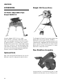
Ridgid® 300 Power Drive
Victaulic Adjustable Pipe
Stand VAPS112
Victaulic Model VAPS 112 (art. code:
R000112PS0), a portable, adjustable, roller
type, four-leg pipe stand for use with Victaulic
roll grooving tools, is available from Victaulic
Europe. Ball transfer rollers, adjustable for pipe
from 26,9 - 323,9 mm, will accommodate linear
and rotational movement. Turnstile design permits easy swivel for grooving both pipe ends.
Contact Victaulic Europe for details.
The Ridgid 300 Power Drive can be used as the
power drive unit for the VE226, VE266FS,
VE272FS and VE416FS roll grooving tools, provided the tool is equipped with the correct base
plate. It utilizes a 50 Hz universal motor and requires 230 V/1 Phase 15 A of power. It is operated with a safety foot switch.
Pipe Stabilizer Assembly
Optional Rolls
See "Tool Rating and Roll Selection" for rolls for
different materials and groove specifications.
A pipe stabilizer is available for this tool. It is designed to prevent pipe sway on IPS pipe sizes
32
VE272FS
of 219,1 mm and above. Contact Victaulic Europe for details.
33
VE272FS
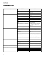
TROUBLESHOOTING
Problem
Pipe will not stay in grooving rolls.
Pipe stops rotating during grooving.
Possible Cause
Solution
Incorrect pipe positioning.
See Pipe Support section.
Improper manual grooving technique.
See "Grooving Operation" - Grooving Short Pipe
Lengths section.
Power Drive running counterclockwise
See "Tool Setup".
Rust or dirt has built up on lower roll.
Remove accumulation from lower roll with stiff
wire brush.
Rust or dirt is excessively heavy inside the pipe
end.
Remove heavy rust and dirt from inside pipe end.
See "Pipe Preparation".
Worn grooving rolls.
Inspect lower roll for worn knurls, replace if worn.
Power drive chuck is not engaged onto drive
shaft.
See "Tool Setup".
Woodruff keys under lower roll are damaged or
missing.
Remove lower roll, replace key and reinstall lower
roll. See "Roll Changing".
Motor has stalled due to excess hand pumping.
Open release valve to free pipe, close release
valve and continue grooving, pumping at a
moderate rate.
Circuit breaker has tripped or fuse has blown on Reset breaker or replace fuse.
electrical circuit supplying motor.
Pipe flare is excessive.
Pipe support adjusted too high on long pipes.
See "Long Pipe Lengths".
Tool is tilted forward.
Check tool levelness. See Tool Setup section.
Incorrect pipe support positioning, pipe is
"overtracking".
Move pipe support to the right. See Pipe Support
section.
Stabilizer(s) is pushing pipe to the left and off
center from the rolls.
Back off stabilizer(s) to the furthest point where it
still stabilizes pipe effectively. See Stabilizer
Adjustment section.
Incorrect stabilizer adjustment.
Move stabilizer in or out until pipe rotates
smoothly. See Stabilizer Adjustment section.
Optional stabilizer was not purchased, installed
and used.
Purchase, install and use optional stabilizer.
Pipe not square cut.
Cut pipe end squarely.
Incorrect pipe support positioning, pipe is
"overtracking".
Move pipe support to the right. See Pipe Support
section.
Pipe is rubbing excessively hard on lower roll
flange.
Remove pipe from tool and apply a film of grease
to the face of the lower roll flange as needed.
During grooving, loud thumps or bangs occur about once
every revolution of the pipe.
Pipe has a pronounced weld seam.
Grind welds flush with pipe surface inside and
out 51 mm back from pipe end.
Tool won't groove pipe.
Hand pump valve is not closed tightly.
Tighten valve.
Hand pump is low on oil.
See "Maintenance".
Air in hydraulic system.
See "Maintenance".
Pipe beyond tool's wall thickness capability.
See "Tool Rating and Roll Selection".
Pipe vibrates or sways from side to side.
While grooving, loud squeaks echo through the pipe.
34
VE272FS
TOOL RATING AND ROLL SELECTION
Standard and "ES" Rolls - Color Coded Black
1
2
3
4
Nominal Wall Thickness Dimensions - [mm]
O.D.
[mm]
Aluminum Pipe
PVC Plastic Pipe
Min.
Steel Pipe
Max.
Stainless Steel Pipe
Min.
Max.
Min.
Max.
Min.
Max.
60,3
1,65
3,91
3,91
3,91
1,70
3,91
3,91
3,91
73,0
2,11
5,16
5,16
5,16
2,11
5,16
5,16
7,01
88,9
2,11
5,49
5,49
5,49
2,11
5,49
5,49
7,62
101,6
2,11
5,74
5,74
5,74
2,11
5,74
5,74
8,07
114,3
2,11
9,53
6,02
6,02
2,11
6,02
6,02
8,55
127,0
2,41
9,53
6,02
6,02
2,41
6,02
-
-
141,3
2,77
9,53
6,55
6,55
2,77
6,55
6,55
9,53
152,4
2,77
9,53
6,55
6,55
2,77
6,55
-
-
168,3
2,77
9,53
7,11
7,11
2,77
7,11
7,11
10,97
203,2
2,77
9,53
6,35
8,22
2,77
8,22
-
-
219,1
2,77
9,53
6,35
8,22
2,77
8,22
8,22
12,70
273,0
3,40
9,53
6,35
9,27
3,40
6,35
9,27
15,06
323,9
4,00
9,53
6,35
9,53
3,96
6,35
10,30
17,45
Standard
Roll Nos.
"ES" Roll
Nos.
Lower Roll
R902272L03
Lower Roll
RZ02272L03
Upper Roll
Upper Roll
R9A2268U06 RZA2268U03
Lower Roll
R904272L06
Lower Roll
RZ04272L06
Upper Roll
Upper Roll
R9A2268U06 RZA4268U06
Lower Roll
R908272L12
Lower Roll
RZ08272L12
Upper Roll
Upper Roll
R9A8268U12 RZA8268U12
Notes for Standard and "ES" Rolls:
COLUMN 1: Steel Pipe – Maximum ratings on steel are limited to pipe of 180 BHN (Brinnel Hardness Number) and less.
COLUMN 2: Stainless Steel Pipe – Types 304/304L and 316/316L
COLUMN 3: Aluminum Pipe – Alloys 6061-T4 and 6063-T4
COLUMN 4: PVC Plastic Pipe – PVC Type I Grade I - PVC1120; PVC Type I Grade II - PVC1220; PVC Type II Grade I - PVC2116
The following pipe sizes may also be grooved: 76,1 mm., 108,0 mm., 133,0 mm, 139,7 mm., 159,0 mm, 165,1 mm, 254,0 mm and 304,8 mm. Contact Victaulic
Europe for details.
35
VE272FS
Rolls for Stainless Steel Pipe† (RX Rolls) - Color Coded Silver
Nominal Wall Thickness - [mm]
O.D.
[mm]
Sched. 5S
Sched. 10S
60,3
1,70
2,80
73,0
2,10
3,00
88,9
2,10
3,00
101,6
2,10
3,00
114,3
2,10
3,00
141,3
2,80
3,40
168,3
2,80
3,40
219,1
2,80
3,80
273,0
3,40
4,20
323,9
4,00
4,60
RX Roll Nos.
Lower
Upper
RX02272L03
RXA2268U06
RX04272L06
RX08272L12
RXA8268U12
† Types 304/304L and 316/316L
Rolls for Copper Tubing - Color Coded Copper†
Nominal Wall Thickness - [mm]
O.D.
[mm]
Min.
Max.
54,0
1,1
2,1
66,7
1,7
2,4
79,4
1,1
2,8
104,8
1,5
3,4
130,2
1,8
4,1
155,6
2,1
4,9
206,4
2,8
6,9
Copper Roll Nos.
Lower
RR02272L06
Upper
RRA2268U08
RR08272L08
Drawn copper tubing - DWV, ASTM B306, Type "M", ASTM B88 - Type "L", ASTM B88 - Type "K", ASTM B88.
Rolls are available for grooving British Standard, Australian Standard and DIN Standard copper tube, contact Victaulic Europe for details.
36
VE272FS
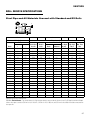
ROLL GROOVE SPECIFICATIONS
Steel Pipe and All Materials Grooved with Standard and RX Rolls
B
A B
OD
T
C
D
1
2
3
4
O.D. - [mm]
5
6
7
Dimensions - [mm]
Tolerance
Groove
Width B
±0,76
Groove Dia. C
Basic
Tolerance
Grv. Depth
D (ref.)
Min. Wall
Thk. T
Max. Flare
Dia.
Basic
+
-
Gasket Seat
A ±0,76
60,3
0,61
0,61
15,88
8,74
57,15
-0,38
1,60
1,65
63,0
73,0
0,74
0,74
15,88
8,74
69,09
-0,46
1,98
2,11
75,7
76,1
0,76
0,76
15,88
8,74
72,26
-0,46
1,98
2,11
78,7
88,9
0,89
0,89
15,88
8,74
84,94
-0,46
1,98
2,11
91,4
101,6
1,02
0,79
15,88
8,74
97,38
-0,51
2,11
2,11
104,1
108,0
1,04
0,79
15,88
8,74
103,73
-0,51
2,11
2,11
110,5
114,3
1,14
0,79
15,88
8,74
110,08
-0,51
2,11
2,11
116,8
127,0
1,27
0,79
15,88
8,74
122,78
-0,51
2,11
2,41
129,5
133,0
1,34
0,79
15,88
8,74
129,13
-0,51
2,11
2,77
135,9
139,7
1,42
0,79
15,88
8,74
135,48
-0,51
2,11
2,77
142,2
141,3
1,42
0,79
15,88
8,74
137,03
-0,56
2,13
2,77
143,8
152,4
1,42
0,79
15,88
8,74
148,06
-0,56
2,16
2,77
154,9
159,0
1,60
0,79
15,88
8,74
153,21
-0,56
2,16
2,77
161,3
165,1
1,60
0,79
15,88
8,74
160,78
-0,56
2,16
2,77
167,6
168,3
1,60
0,79
15,88
8,74
163,96
-0,56
2,16
2,77
170,9
203,2
1,60
0,79
19,05
11,91
198,53
-0,64
2,34
2,77
207,5
219,1
1,60
0,79
19,05
11,91
214,40
-0,64
2,34
2,77
223,5
254,0
1,60
0,79
19,05
11,91
249,23
-0,69
2,39
3,40
258,3
273,0
1,60
0,79
19,05
11,91
268,28
-0,69
2,39
3,40
277,4
304,8
1,60
0,79
19,05
11,91
299,24
-0,76
2,77
3,96
309,1
323,9
1,60
0,79
19,05
11,91
318,29
-0,76
2,77
3,96
328,2
Standard roll groove specifications notes:
COLUMN 1: Outside diameter – The outside diameter of roll grooved pipe shall not vary more than the tolerance listed. For IPS pipe the maximum allowable
tolerance from square cut ends is 0,762 mm for 26,9 - 101,6 mm; 1,143 mm for 114,3 - 168,3 mm; and 1,524 mm for sizes 203,2 mm and above measured from
true square line.
37
VE272FS
COLUMN 2: Gasket seat – The pipe surface shall be free from indentations, roll marks, and projections from the end of the pipe to the groove, to provide a
leak-tight seal for the gasket. All loose paint, scale, dirt, chips, grease and rust must be removed. It continues to be Victaulic’s first recommendation that pipe
be square cut. When using beveled pipe contact Victaulic for details. Square cut pipe must be used with FlushSeal® and EndSeal® gaskets. Gasket seat "A" is
measured from the end of the pipe.
IMPORTANT: Roll grooving of beveled end pipe may result in unacceptable pipe end flare. See column 7.
COLUMN 3: Groove width – Bottom of groove to be free of loose dirt, chips, rust and scale that may interfere with proper coupling assembly. Corners at bottom of groove must have a radius of the following dimensions. For IPS steel pipe, 0,06R on 26,9 - 48,3 mm, 0,08R on 60,3 - 168,3 mm, 0,05R on 219,1 mm and
up.
COLUMN 4: Groove outside diameter – The groove must be of uniform depth for the entire pipe circumference. Groove must be maintained within the "C"
diameter tolerance listed.
COLUMN 5: Groove depth – For reference only. Groove must conform to the groove diameter "C" listed.
COLUMN 6: Minimum allowable wall thickness – This is the minimum wall thickness which may be roll grooved – except PVC.
COLUMN 7: Maximum allowable pipe end flare diameter – Measured at the most extreme pipe end diameter square cut or beveled.
38
VE272FS
Drawn Copper Tubing
B
A B
OD
T
C
D
1
2
3
O.D. - [mm]
4
5
6
7
Dimensions - [mm]
Basic
Tolerance
Gasket Seat A
±0,76
Groove Width
B +0,76/-0,00
Groove Diame- Groove Depth
ter C +0,00
(ref.) D
Min. Wall Thk.
T
Max. Flare Dia.
54,0
±0,05
15,5
7,6
51,5
1,2
1,6
66,7
±0,05
15,5
7,6
64,1
1,2
1,7
69,1
79,4
±0,05
15,5
7,6
76,8
1,2
DWV
81,8
104,8
±0,05
15,5
7,6
102,1
1,4
DWV
107,2
130,2
±0,05
15,5
7,6
127,0
1,4
DWV
132,6
155,6
±0,05
15,5
7,6
152,3
1,6
DWV
158,0
206,4
+0,05/-0,10
15,5
7,6
202,2
2,1
DWV
208,8
56,4
Copper tubing roll groove specifications notes:
COLUMN 1: Outside diameter – The outside diameter of roll grooved tubing shall not vary more than the tolerance listed. The maximum allowable tolerance
from square cut ends is 0,762 mm for 54,0 - 79,4 mm; 1,143 mm for 104,8 - 155,6 mm, measured from true square line.
COLUMN 2: Gasket seat – The tubing surface shall be free from indentations, roll marks, and projections from the end of the tubing to the groove, to provide a
leak-tight seat for the gasket. All loose scale, dirt, chips and grease must be removed.
COLUMN 3: Groove width – Bottom of groove to be free of loose dirt, chips and scale that may interfere with proper coupling assembly.
COLUMN 4: Groove outside diameter – The groove must be of uniform depth for the entire pipe circumference. Groove must be maintained within the "C"
diameter tolerance listed.
COLUMN 5: Groove depth – For reference only. Groove must conform to the groove diameter "C" listed.
COLUMN 6: Minimum allowable wall thickness – ASTM B-306 drain waste and vent (DWV) is minimum wall thickness copper tubing which may be roll
grooved.
COLUMN 7: Maximum allowable pipe end flare diameter – Measured at the most extreme pipe end diameter.
39
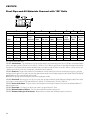
VE272FS
Steel Pipe and All Materials Grooved with "ES" Rolls
B
A B
OD
T
C
D
1
2
3
4
O.D. - [mm]
5
6
7
Dimensions - [mm]
Tolerance
Basic
+
-
Gasket
Seat A
+0,00/-0,51
Groove Width B
Groove Diameter C
Basic
Tol. -0,00
Basic
Tol. +0,00
Groove
Depth
(ref.) D
60,3
+0,61
-0,61
14,53
6,35
+0,38
57,15
-0,38
1,60
1,65
63,0
73,0
+0,74
-0,74
14,53
6,35
+0,38
69,09
-0,46
1,98
2,11
75,7
88,9
+0,89
-0,79
14,53
6,35
+0,38
84,94
-0,46
1,98
2,11
91,4
114,3
+1,14
-0,79
15,49
7,62
+0,51
110,08
-0,51
2,11
2,11
116,8
168,3
+1,60
-0,79
15,49
7,62
+0,51
163,96
-0,56
2,16
2,77
170,9
219,1
+1,60
-0,79
18,26
9,91
+0,51
214,40
-0,64
2,34
2,77
223,5
273,0
+1,60
-0,79
18,26
9,91
+0,51
268,28
-0,69
2,39
3,40
277,4
323,9
+1,60
-0,79
18,26
9,91
+0,51
318,29
-0,76
2,77
3,96
328,2
Min. Wall Max. Flare
Thk. T
Dia.
"ES" roll groove specifications notes:
COLUMN 1: Outside diameter – The outside diameter of roll grooved pipe shall not vary more than the tolerance listed. For IPS pipe, the maximum allowable
tolerance from square cut ends is 0,762 mm for 26,9 - 101,6 mm; 1,143 mm for 114,3 - 168,3 mm; and 1,524 mm for sizes 203,2 mm and above measured from
true square line. For (ISO) metric pipe, the maximum allowable tolerance from square cut ends is 0,762 mm for sizes 26,9 - 88,9 mm; 1,143 mm for sizes 114,3
- 168,3 mm; and 1,524 mm for sizes 219,1 mm and above, measured from the true square line.
COLUMN 2: Gasket seat – The pipe surface shall be free from indentations, roll marks, and projections from the end of the pipe to the groove, to provide a
leak-tight seal for the gasket. All loose paint, scale, dirt, chips, grease and rust must be removed. Square cut pipe must be used with FlushSeal® and EndSeal®
gaskets. Gasket seat "A" is measured from the end of the pipe.
IMPORTANT: Roll grooving of beveled end pipe may result in unacceptable pipe end flare.
COLUMN 3: Groove width – Bottom of groove to be free of loose dirt, chips, rust and scale that may interfere with proper coupling assembly. Corners at bottom of roll groove must be radiused. For IPS pipe, 0,04R on 48,3 - 323,9 mm. For (ISO) metric pipe, 1,2R on 26,9 - 323,9 mm.
COLUMN 4: Groove outside diameter – The groove must be of uniform depth for the entire pipe circumference. Groove must be maintained within the "C"
diameter tolerance listed.
COLUMN 5: Groove depth – For reference only. Groove must conform to the groove diameter "C" listed.
COLUMN 6: Minimum allowable wall thickness – This is the minimum wall thickness which may be grooved.
COLUMN 7: Maximum allowable pipe end flare diameter – Measured at the most extreme pipe end diameter square cut or beveled.
40
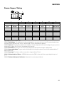
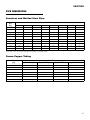
VE272FS
PIPE DIMENSIONS
Seamless and Welded Steel Pipe†
Nominal Wall Thickness - [mm]
O.D.
[mm]
Sched. 5S
Sched. 10S
Sched. 10
Sched. 20
Sched. 30
Sched. 40
Sched. STD
Sched. 80
60,3
1,7
2,8
-
-
-
3,9
3,9
5,5
73,0
2,1
3,0
-
-
-
5,2
5,2
7,0
88,9
2,1
3,0
-
-
-
5,5
5,5
7,6
101,6
2,1
3,0
-
-
-
5,7
5,7
8,1
114,3
2,1
3,0
-
-
-
6,0
6,0
8,6
141,3
2,8
3,4
-
-
-
6,6
6,6
9,5
168,3
2,8
3,4
-
-
-
7,1
7,1
11,0
219,1
2,8
3,8
-
6,4
7,0
8,2
8,2
12,7
273,0
3,4
4,2
-
6,4
7,8
9,3
9,3
15,1
323,9
4,0
4,6
-
6,4
8,4
10,3
9,5
17,4
† For reference only. The VE272FS cannot groove all schedules of steel pipe in table.
Drawn Copper Tubing
Nominal Wall Thickness - [mm]
O.D.
[mm]
DWV ASTM B-306
Type "M" ASTM B-88
Type "L" ASTM B-88
Type "K" ASTM B-88
54,0
1,1
1,5
1,8
2,1
66,7
-
1,7
2,0
2,4
79,4
1,1
1,8
2,3
2,8
104,8
1,5
2,4
2,8
3,4
130,2
1,8
2,8
3,2
4,1
155,6
2,1
3,1
3,6
4,9
206,4
2,8
4,3
5,1
6,9
41
how to contact Victaulic Europe
R
Victaulic Europe
Prijkelstraat 36
B-9810 Nazareth
Belgium
tel: +32-9-381.15.00
fax: +32-9-380.44.38
e-mail: [email protected]
www.victaulic.com/europe
Victaulic Europe subsidiaries
Victaulic Polska
R
Ul. Niepodleglosci 8
66530 Drezdenko
Poland
Victaulic Espana
R
Avda. De Milan 18
19200 Azuqueca de Henares
Spain
Victaulic Middle East
R
PO box 17683
Jebel Ali
United Arab Emirates
Victaulic reserves the right to change product specifications, designs
and standard equipment without notice and without obligation.
TM–VE272FS
Rev. 25/07/2001