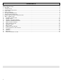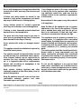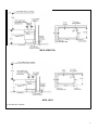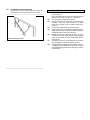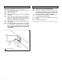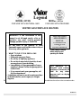
1
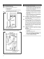
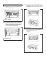
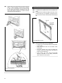
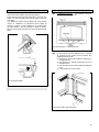
Legend
MODEL 937XN
FOR USE WITH NATURAL GAS
MODEL 937XP
FOR USE WITH PROPANE
VENTED GAS FIREPLACE HEATERS
WARNING: If the information in this
manual is not followed exactly, a fire or
explosion may result causing property
damage, personal injury or loss of life
- Do not store or use gasoline or other
flammable vapors and liquids in the vicinity of
this or any other appliance.
INSTALLATION
AND OWNER’S
MANUAL
For Pedestal base with
Contemporary front
or
Legs with Traditional front
Please read this manual
before installing and
operating this heater.
- WHAT TO DO IF YOU SMELL GAS
• Open windows
• Extinguish any open flame
• Do not try to light any appliance.
• Do not touch any electrical switch; do not
use any phone in your building.
• Immediately call your gas supplier from a
This appliance is a
neighbor’s phone. Follow the gas supplier’s
domestic room heating
instructions.
appliance. It must not be
• If you cannot reach your gas supplier, call
used for any other
the fire department.
purpose such as drying
- Installation and service must be performed by a
clothes etc.
qualified installer, service agency or the gas
supplier.
Vous pourrez vous procurer un exemplaire en langue française de cette brochure chez votre concessionnaire
600B257/01
CONTENTS
SAFETY INFORMATION...................................................................................................................................................................................................... 3
1
OPTIONS......................................................................................................................................................................................................................... 4
2. GENERAL DATA............................................................................................................................................................................................................. 4
3. LOCATION IN THE ROOM ........................................................................................................................................................................................ 4
4. SUPPLY GAS..................................................................................................................................................................................................................... 4
5. PACK CONTENTS......................................................................................................................................................................................................... 6
6. APPLIANCE PREPARATION........................................................................................................................................................................................ 6
7. GAS SUPPLY INSTALLATION..................................................................................................................................................................................... 7
8. BASE & MAIN APPLIANCE INSTALLATION .......................................................................................................................................................... 8
9. VENT CONNECTION.................................................................................................................................................................................................. 9
10.
GAS LINE CONNECTION..................................................................................................................................................................................... 10
11.
SYSTEM CHECK ....................................................................................................................................................................................................... 10
12.
CERAMIC FUEL BED ASSEMBLY......................................................................................................................................................................... 11
13.
CONTROLS OPERATION CHECK ...................................................................................................................................................................... 12
14.
AERATION ADJUSTMENT.................................................................................................................................................................................... 13
15.
FASCIA INSTALLATION ........................................................................................................................................................................................ 13
16.
VENTING CHECK ................................................................................................................................................................................................... 14
17.
FINAL CHECK .......................................................................................................................................................................................................... 14
18.
OPERATING THE HEATER.................................................................................................................................................................................... 15
19.
LIGHTING WITH A LONG MATCH.................................................................................................................................................................... 15
20.
CLEANING................................................................................................................................................................................................................ 15
21.
CHECKS...................................................................................................................................................................................................................... 16
22.
SERVICING................................................................................................................................................................................................................ 16
23.
LIGHTING INSTRUCTIONS................................................................................................................................................................................. 17
2
SAFETY INFORMATION
Due to high temperatures, the appliance should be
located out of traffic and away from furniture and
draperies.
Children and adults should be alerted to the
hazards of high surface temperatures and should
stay away to avoid burns or clothing ignition.
Young children should be carefully supervised
when they are in the same room as the appliance.
Clothing or other flammable material should not
be placed on or near the appliance.
The glass and front frame must be put back in
place prior to operating the appliance if they have
been removed for servicing or cleaning.
Never operate with broken or damaged window
glass.
This appliance should be installed and repaired by
a qualified service person.
The appliance should be inspected before use and
at least annually by a professional service person.
More frequent cleaning may be required due to
excessive lint from carpeting, bedding material,
etc. It is imperative that control compartments,
burners and circulating air passageways of the
appliance are kept clean.
Keep curtains, clothing, furniture and other
flammable materials at least 36ins (90cm) from all
parts of the appliance
If any changes are made to the room construction
in the vicinity of the appliance after installation
(e.g. additional mantle etc.) make sure that the
changes conform to the installation requirements
in this manual.
Never attempt to burn paper or any other material
in the appliance.
Keep the base of the appliance clear to prevent
obstruction of air flow to the appliance. If fitted
with a pedestal base, make sure that the grill at
back is not obstructed. If fitted with legs, make
sure there is no obstruction between the legs.
This appliance must be properly connected to a
venting system. It is equipped with a vent safety
shutoff system. Operating when not connected to a
properly installed and maintained venting system
or tampering with the shutoff system can result in
carbon monoxide (CO) poisoning and possible
death.
The venting system should be checked periodically.
Recent trends in home improvement and new
tighter construction techniques have contributed
to problems with venting. If you suspect that your
appliance is not venting properly, do not operate.
Seek expert advice.
Do not use this appliance if any part has been
under water. Immediately call a qualified service
technician to inspect the appliance and to replace
any part of the control system and any gas control
which has been under water.
Keep the appliance area well clear and free from
combustible materials, gasoline and other
flammable vapors and liquids.
NOTE
When operating your new stove for the first time, some vapors may be released which may cause a slight odor and could possibly set off any smoke
detection alarms in the immediate vicinity. These vapors are quite normal on new appliances. They are totally harmless and will disappear after a few
hours use.
3
1
OPTIONS
#710 CFK Circulating fan kit (For pedestal base only) is available
as an option for this appliance. Operated by a variable speed
controller, it is designed to boost the natural convection process
through the heater. It may be fitted before the heater is installed
or retrofitted at a later date. Full installation and operating
instructions are included with the kit.
2.
GENERAL DATA
This appliance is certified by International Approval Services for
use in Canada and the USA.
The appliance complies with CGA P.4.1, Testing method for
measuring annual fireplace efficiencies.
The installation must conform with local codes or, in the absence
of local codes with the National Fuel Gas Code, ANSI Z223.1 or
the Canadian installation code CAN/CGA-149. Only qualified
licensed or trained personnel should install the appliance.
The appliance, when installed, must be electrically grounded in
accordance with local codes or, in the absence of local codes, with
the National Electrical Code, ANSI/NFPA 70 or the Canadian
Electrical Code, CSA C22.1
This appliance is only for use with the type of gas indicated on the
rating plate.
2.1
Rating plate
2.2
Rates (Btu/h)
Altitude
(feet)
The rating plate is located inside the control compartment
door.
Natural gas
Max
Min
0-4500
27,000
Input
0-4500
19,000
Output
2.3
Pressures (in. w.c.)
Natural. gas
Supply upstream
of
regulator
Max
Min
4
10.5
5.0
Manifold tapping on
thermostat
(appliance
full on)
3.7
3.3
8,000
Propane
Max
Min
26,500
18,815
8,000
Propane
Supply upstream
of
regulator
14.0
11.0
Manifold tapping on
thermostat
(appliance
full on)
9.5
9.1
2.4
Orifice data
2.5
Venting
For verification only. Do not attempt to drill or otherwise modify
the appliance input.
Natural Gas
Propane
Type
No of Dia.
Type
No of Dia.
holes
(ins)
holes
(ins)
Pilot
40
1
0.022
14
1
0.014
Front
187
0.027
105
1
0.042
360
Rear
187
0.027
105
1
0.042
360
This appliance is for connection to an approved 4” metal
vent.
3.
LOCATION IN THE ROOM
Combustible materials inside the room must not be closer than
the dimensions shown in figure 1.
The floor construction should allow the heater to be screwed to
the floor. If the heater is to be installed directly on any
combustible material other than wood flooring, it must be
installed on a metal or wood panel extending the full width and
depth of the appliance.
4.
SUPPLY GAS
Model 937XN is for use only with natural gas. Model 937XP is
for use only with propane gas. The supply pressure must be
between the limits shown in section 2.3 of this manual.
The supply connection is 3/8”NPT. Openings for the gas supply
are provided for rear or underfloor connection (see figure 1).
WITH PEDESTAL
WITH LEGS
Fig. 1 Dimensions & clearances
5
5.
PACK CONTENTS
The complete appliance is contained in two packs. One of the
alternative base support and front designs will be included - either
pedestal with contemporary fascia or Legs with traditional fascia
(See pack 2).
Pack 1 - Main appliance unit contains:1
Main appliance fitted with window.
4
Ceramic logs.
1
Pair ceramic firebox side walls.
1
Ceramic firebox back wall.
1
Decorative vent collar for appliance top.
1
Gas supply inlet pipe.
1
Gas supply inlet elbow.
1
Exhaust port cover
Pack 2 - Pedestal and contemporary fascia alternative
contains:1
Pedestal unit.
1
Contemporary design front fascia unit.
1
Ashlip unit.
4
#8 tapping screws (for fixing ashlip).
4
Machine screws (for fixing pedestal to main appliance).
2
Wood screws (for floor fixing).
2
Plugs (for floor fixing).
or
Pack 2 - Legs and traditional fascia alternative contains:1
Base & legs unit.
1
Traditional design front fascia unit.
1
Door retaining bracket.
1
Window frame top cover.
2
#10 tapping screws (for door retaining bracket).
4
Machine screws (for fixing base & leg unit to main
appliance).
2
Wood screws (for floor fixing).
2
Plugs (for floor fixing).
Take care when removing the contents from the packaging to
prevent damage. Check that all the contents are in the packs and
are undamaged.
6.
6.1
6.1.1
6.1.2
6.1.3
APPLIANCE PREPARATION
Remove the window & logs (see figure 2)
Detach the window unit by removing the two knurled
screws (“A”) and knurled nut (“B”) holding the sides and
bottom of the window frame.
Lift the window unit up and forwards to unhook the top.
Put the window in a safe place.
Take the ceramic logs out of the firebox and store safely.
Fig. 2 Window removal
6.2
Check ignition electrode spark (see figure 3)
The pilot burner and electrode are at the right side of the
firebox.
Open the control access door. Turn the gas control knob
(the right hand knob) counterclockwise to “Ign”. While
turning pilot ignition sparks should be activated twice.
Check that the sparks are produced at the pilot burner.
If no sparks are produced, check that the wiring is secure
and that the spark gap is 3.5 + 0.5 mm.
Fig. 3 Pilot ignition system
6
6.3
Fit exhaust port cover (see figure 4)
Remove four screws from under the top of the firebox. Fit
the exhaust port cover and secure with the four screws.
7.
7.1
7.2
7.3
7.4
7.5
7.6
Figure 4 Exhaust port cover
7.7
7.8
GAS SUPPLY INSTALLATION
Route the gas supply line to the appliance inlet connection
point (see figure 1).
Note: Pressure testing the line for leaks may need to be performed
before the line is connected to the appliance - see section 10.
Gas connection to the appliance is 3/8”NPT.
Use only new black iron or steel pipes or copper tubing if
acceptable - check local codes. Note that in USA copper
tubing must be internally tinned for protection against sulfur
compounds.
Unions in gas lines should be of ground joint type.
The gas supply line must be sized and installed to provide a
supply of gas sufficient to meet the maximum demand of
the appliance without undue loss of pressure.
Sealants used must be resistant to the action of all gas
constituents including LP gas. Sealants should be applied
lightly to male threads to ensure excess sealant does not
enter gas lines.
The supply line should include a manual shut-off valve to
allow the appliance to be disconnected for servicing.
A plugged 1/8”NPT tapping must be installed in the line.
The tapping must be accessible for test gauge connection
and be immediately upstream of the gas supply connection
to the appliance.
7
8.
BASE & MAIN APPLIANCE INSTALLATION
8.1
8.1.1
8.1.2
PEDESTAL BASE
Detach the pedestal front panel by removing two screws.
Place the pedestal in position (see figure 5). The bottom
rear of the pedestal must be at least 2½” from the back wall
to maintain the 2” rear clearance shown in figure 1.
8.1.3 Mark the floor with the floor fixing positions through the
holes in the pedestal (see figure 5).
8.1.4 Remove the pedestal. Drill the floor at the marked
positions and fit plugs if necessary.
8.1.5 For easier fixing, fit the two woodscrews supplied into the
floor partially leaving a space between the screw heads and
the floor. The pedestal has two “keyhole” openings in its
bottom channels. Place the pedestal back in position by
dropping it to locate the screws in the wide holes of the
keyholes and then sliding the pedestal back to locate the
screws in the narrow slots of the keyholes. Tighten the
screws.
8.1.6 Fit the inlet elbow to the supply pipe.
Note: If the optional circulating fan kit is intended to be installed,
it will be easiest to fit it at this stage
8.1.7 Place the main appliance unit over the pedestal, align the 4
fixing holes (2 at each side) and secure the unit to the
pedestal with 4 machine screws.
8.2
8.2.1
REMOVE BRACKET
BASE WITH LEGS
Detach the door retaining bracket (located near the rear
SWING DOOR FORWARD
Fig. 6 Door removal
8.2.8
Place the main appliance unit over the base, align the
securing holes (see figure 7). Secure with 4 machine
screws.
Fig. 5 Pedestal positioning
right corner of the appliance main unit) by removing two
screws (see figure 6).
8.2.2. Swing the bottom of the door forward to release the
bottom pin from the slot in the case and lift the door clear
(see figure 6).
8.2.3 Place the base in position (see figure 7). The rear of the
base must be at least 2” away from the rear wall to allow
air flow to the installed appliance.
8.2.4 Mark the floor fixing positions through the holes in the
rear feet.
8.2.5 Remove the base. Drill the floor at the marked positions
and fit plugs if necessary.
8.2.6 Replace the base. Fit woodscrews through the rear feet and
tighten.
8.2.7 Fit the inlet elbow to the supply pipe.
8
Fig.7 Leg base positioning
8.2.9 Replace the door as follows:
8.2.9.1 Locate the hinge pin at top of the door into the hole at
8.2.9.2
the top of the door aperture (see figure 8).
Locate the hinge pin at bottom of the door into the slot
in the base. Swing the bottom of the door part way to
the back. A new door-retaining bracket is supplied with
the leg and fascia kit. Hold this bracket under the
bottom of the base side. Position it with the two holes at
LOCATE TOP DOOR HINGE PIN
FIT BRACKET TO HINGE PIN & SWING BACK
8.2.9.3
the bottom and locate the single hole over the bottom
door hinge pin (see figure 8).
While keeping the bracket located to the hinge pin,
swing the door and bracket fully backwards. Align the
two holes in the bracket with the two holes in the base
side and fix with the two tapping screws provided (see
figure 8).
LOCATE BOTTOM HINGE PIN IN SLOT & SWING
DOOR PART WAY TO BACK
SECURE BRACKET WITH 2 SCREWS
Fig. 8 Door fitting with leg design base
9.
VENT CONNECTION
Connect an approved 4” vent unit to the appliance vent collar.
A decorative vent collar is supplied with the appliance to cover the
vent and appliance collar joint at the top of the heater.
9
10.
10.1
10.2
10.3
10.4
GAS LINE CONNECTION
Open the control panel door.
Pull off the two control knobs.
Detach the control cover panel (see figure 9):• Remove three screws.
• Lift the panel up
• Pull the bottom front corner of the panel forward and
out to clear the case and then lift clear.
Couple the gas inlet pipe to the connector below the
11.
11.1
11.2
11.3
11.4
Fig. 9 Control cover panel removal
regulator (see figure 10).
10.5 Connect the other end of the inlet pipe to the elbow
Fig. 10 Inlet pipe connection & pressure test point
attached to the supply line.
10
SYSTEM CHECK
Pressure test the supply line for leaks.
• The appliance and its individual shut-off valve must
be disconnected from the gas supply piping system
during any pressure testing of that system at test
pressures in excess of ½psig (3.5kPa).
• The appliance must be isolated from the gas supply
piping system by closing its individual manual shutoff valve during any pressure testing of the gas supply
piping system at test pressures equal to or less than
½psig (3.5kPa).
• Failure to either disconnect or isolate the appliance
during pressure testing may result in regulator or valve
damage. Consult your dealer in this case.
The appliance is preset to give the correct input with
natural gas. For input adjustment, the gas supply pressure
to the appliance inlet must within the range shown in
section 2 of this manual.
The burner manifold pressure is controlled by a built-in
non-adjustable regulator. The correct pressure range is
shown in the table in section 2 of this manual. The
manifold pressure should be checked at the pressure test
point which is located on the thermostat unit (see figure
10). The pressure check should be made with the
appliance burning, the gas control set at “On” and the
thermostat control set at “Full”. (Temporarily refit the
control knobs for checking.)
All piping and connections must be tested for leaks after
installation or servicing. All leaks must be corrected
immediately.
When testing for leaks:
• Make sure that the appliance gas control knob is at the
“Off” position.
• Open the manual shut-off valve.
• Test for leaks by applying a liquid detergent or soap
solution to all joints. Bubbles forming indicate a gas
leak. Never use an open flame to check for leaks.
• Correct any leak detected immediately.
12.
12.1
CERAMIC FUEL BED ASSEMBLY
12.3
Place the ceramic back wall in position centrally at the
back of the firebox. It must rest on the metal ledge at the
back of the firebox (see figure 11).
Place the rear log in the retaining cradle behind the rear
burner tube with its back against the back wall. Center the
log so that the gap to the side wall is the same at each side
(see figure 13).
Fig. 11. Back wall position
12.2
Place the ceramic side walls in position at the sides of the
firebox. The sides are left and right handed. The sides
should locate in the sloping channels near the bottom of
the firebox sides and in the gap between each side of the
firebox and the black top baffle (see figure 12).
Fig.13 Rear log position
12.4
Place the center log on the retaining cradles between the
rear and front burner tubes. Center the log so that the gap
to the side wall is the same at each side
(see figure 14).
Fig. 12 Side walls position
Fig. 14 Centre log position
11
12.5
Place the two front logs in position on the front rail of the
firebox. It may be necessary to raise the center log slightly
in order to fit the left-hand front log. Make sure that
there is a gap of approximately ¼” between the front right
stump of the center log and the cut-out section at the rear
of the right front log. See figure 15.
13.
13.1
13.2
13.3
CONTROLS OPERATION CHECK
Refit the control cover panel. Refit the two control knobs
If installed with a pedestal base, refit the pedestal front
panel.
If installed with a traditional design front fascia, fit the
window frame top cover (supplied in the pack) over the
top of the window frame to hide the bare metal (see figure
16).
Fig. 16 Window top cover
13.4
Fig.15 Front Log position
12
Refit the window (with top cover if applicable).
• Hook the top of the window frame over the firebox
top front edge.
• Swing the window down over the bottom center
locating stud.
• Secure the window unit in place by refitting the
knurled nut and two knurled screws at the sides and
bottom of the window frame.
• Check ignition, gas control valve and thermostat
settings as described in the lighting instructions
section further on in this manual.
14.
AERATION ADJUSTMENT
These appliances are equipped with adjustable shutters on both
front and rear burner tubes to control primary aeration.
The air holes are at the right side of the tubes - See fig 17. The
shutters can slide to the right to reduce the air supply or to the left
to increase it.
Your appliance is supplied with the shutters set to suit the vast
majority of installations. No adjustment should usually be
necessary. However, in certain installations (e.g. Low Btu value
gas, high altitude) it may be necessary to adjust the shutter
position of one or both of the burners to obtain the optimal visual
effect.
15.
15.1
FASCIA INSTALLATION
Contemporary front only:
Fit the ashlip to the fascia
unit with 4 screws (see figure 18).
Fig. 18 Ashlip fixing - Contemporary front
Rear burner
15.2
Locate the fascia unit to the appliance front - see figure
19. Locate at the top corners and at the bottom. We
suggest the following order:
1) Angle the top of the fascia against the upper part of
the appliance front.
2) Push the fascia up between the appliance front and
the appliance top.
3) Push the lower part of the fascia against the appliance
front.
4) Lower the fascia on to the locations.
Front burner
Fig. 17 Aeration shutters
Fig. 19 Facia location (Left side shown)
13
16.
VENTING CHECK
A check for correct venting of combustion products must be made
before the installed appliance is left with the customer.
16. 1 Ignite the pilot. Set the main control valve at “MAX” and
the thermostat wheel at “HI”.
16.2 Leave for 15 minutes.
16.3 Find the draft hood opening at the rear of the appliance
near the top.
16.4 Light a long match. Insert the match into the draft hood
opening near the left side (viewed from the front) to a
depth of 2” - See figure 20. The installation is satisfactory
if the smoke does not escape from the opening.
16.5 If smoke spills out of the opening inspect the sealing at the
vent connection.
16.6 If the sealing is satisfactory but the smoke still spills out,
turn the appliance off and check the vent system
thoroughly for cause of lack of pull. If necessary get expert
advice. Do not let the appliance be operated without
correct venting.
Fig. 20 Venting check
14
17.
17.1
17.2
17.3
17.4
17.5
17.6
FINAL CHECK
Recheck gas control and thermostat operation.
Instruct the owner how to operate the appliance.
Advise that, if necessary, the window may be removed
when the appliance is shut off and cold to clean the inside
or reset the logs if disturbed. Stress that the window must
be replaced securely before operating the appliance.
Recommend that the appliance is inspected and, if
necessary, serviced at least once a year.
Point out the location of the supply shut off valve and its
operation.
Close the control panel door.
18.
OPERATING THE HEATER
For full lighting instructions see page 17.
The operating instructions are also inside the control panel door.
18.1 For your safety this appliance is fitted with a flame
supervision device which will shut off the gas supply if,
for any reason, the pilot flames go out. This device
incorporates a fixed probe which senses the heat from the
pilot flame. If the probe is cool, the device will prevent any
gas flow unless the gas control knob is kept pushed in
between the “Off” and “Ign” positions. See full lighting
instructions on next page.
18.2 Open the control panel door at right side of the heater for
access to the controls. Close the door when you have
finished operation the controls.
18.3 The Valor Temperature control system
Conventional thermostats regulate the temperature by
shutting the burners off when the temperature reaches its
upper limit. This gives stop-go heat, unnaturally varying
flames and impaired efficiency (like a car in city traffic).
The Valor system controls the temperature by gradually
lowering or raising the fire. This maintains room comfort
by providing steadier heat and a more natural looking
regulation of the flames. The room temperature will be
maintained at the desired level for any setting up to just
short of the “Full” position. The “Full” position is an
override which will keep the fire fully on all the time and
is not affected by room temperature.
18.4 When first turned on, the decorative flames will appear
predominantly blue. After approximately 15 minutes the
flames will turn yellow.
18.5 After approximately three hours use at the high control
setting the fuel pieces will show areas of charcoal gray
color, as would real burning logs.
19.
20.
20.1
20.2
20.3
20.4
20.5
CLEANING
Only clean when the appliance is cold.
Normally, the appliance should only need dusting. Any
stains on the ceramic glass window can be removed with a
non-abrasive cleaner. Never use abrasive cleaners on the
glass.
Dust, etc. can be brushed from the logs after detaching
the front fascia and window. If you are removing the logs,
we suggest that they are removed in the reverse order to
that shown in the fuel bed assembly instructions. Dust
etc. can also be removed from the burners using a soft
brush after removing the logs. When cleaning the burners
also check the aeration holes (see fig.17) and brush clean if
necessary. Make sure that no particles are brushed into the
burner tubes.
Always replace the ceramic bars, window and fascia after
any cleaning as shown in the installation section of these
instructions.
Coloring of the metal firebox is normal when used. Do
not try to remove the color with abrasive materials.
LIGHTING WITH A LONG MATCH
In the unlikely event of failure to create an ignition spark using
the control knob, the stove can be lit as follows:
19.1 Lift off the front fascia
19.2 Remove the window unit
19.3 Open the control panel door.
19.4 Insert a long burning match at the pilot.
19.5 Operate the controls as described in the lighting
instructions.
19.6 Make sure that the pilot flame is stable.
19.7 Replace the window unit securely.
19.8 Replace the fascia.
19.9 Select the burner setting.
19.10 Close the control panel door.
15
21.
21.1
21.2
21.3
21.4
A periodic visual check of the pilot and burner flames
should be made (see figures 22 & 23).
The appliance area must always be kept clear and free from
combustible materials, gasoline and other flammable
vapors and liquids.
Keep the base of the appliance clear to prevent obstruction
of air flow to the appliance. If fitted with a pedestal base,
make sure that the grill at back is not obstructed. If fitted
with legs, make sure there is no obstruction between the
legs.
The venting system should be examined regularly by a
qualified agency. We suggest an annual check.
Fig. 22 Burner flames
Fig. 23 Pilot flames
16
CHECKS
22.
SERVICING
If you require any attention to your appliance, contact your
supplier quoting the model number. It will be helpful if the
appliance serial number can also be quoted. This is on the rating
plate visible when the control panel door is opened.
The repair parts are shown in the separate repair parts leaflet.
Please always quote part number and description when requesting
spare parts.
23.
LIGHTING INSTRUCTIONS
FOR YOUR SAFETY READ BEFORE LIGHTING
WARNING: If you do not follow these instructions exactly, a fire or explosion may result causing property
damage, personal injury or loss of life.
A. This appliance has a pilot which must be lighted by hand. When lighting the pilot, follow these instructions
exactly.
B. BEFORE LIGHTING smell all around the appliance area for gas. Be sure to smell next to the floor because
some gas is heavier than air and will settle on the floor.
WHAT TO DO IF YOU SMELL GAS
• Do not try to light any appliance.
• Do not touch any electric switch; do not use any phone in your building.
• Immediately call your gas supplier from a neighbor’s phone. Follow the gas supplier’s instructions.
• If you cannot reach your gas supplier, call the fire department.
C. Use only your hand to push in or turn the gas control knob. Never use tools. If the knob will not push in or turn
by hand, don’t try to repair it, call a qualified service technician. Force or attempted repair may result in a fire
or explosion.
D. Do not use this appliance if any part has been under water. Immediately call a qualified service technician to
inspect the appliance and to replace any part of the control system and any gas control which has been under
water.
LIGHTING INSTRUCTIONS
1.
STOP! Read the safety information above on this page .
Thermostat knob
2.
3.
4.
5.
6.
7.
8.
9.
10.
•
•
Gas control knob
Set the thermostat to its lowest setting.
Turn the gas control knob clockwise
to “Off”.
Note; Knob cannot be turned to “Off” unless it is pushed in partially. Do not force.
Wait five (5) minutes to clear out any gas. If you then smell any gas, STOP! Follow “B” in the safety information
above on this label. If you don’t smell gas, go to next step.
Find the pilot. It is at the right side of the firebox.
Push in and turn the gas control knob counter- clockwise
until resistance is felt. Keep pushed in at this
position for a few seconds to allow gas to flow.
Keep knob pushed in and turn to “Ign” to light pilot. While turning to this position ignition sparks will be
activated twice. Hold knob in for a further 5 seconds then release. The knob should pop back up. The pilot
should remain lit. If pilot goes out repeat steps 3 through 7. If pilot does not light at all during a few attempts,
try lighting with a long match as described on previous page.
• If pilot lights but will not stay lit after several tries, turn the gas control knob to “Off” and call your service
technician or gas supplier.
When pilot is lit, partially depress the gas control knob and turn counterclockwise
to “On”.
• Do not leave knob set between “Ign” and “On”.
Set thermostat to desired setting.
Close control access door.
Always replace the window unit after match lighting the pilot.
The gas control knob should always pop up when released. If it does not, stop and immediately call your service
technician or gas supplier.
TO TURN OFF GAS TO APPLIANCE
1.
2.
3.
Set the thermostat to lowest setting.
Push in the gas control knob and turn clockwise
Close control access door.
to “Off”. Do not force.
17
Manufactured by
HEATING
BIRMINGHAM, ENGLAND
Because our policy is one of constant development and improvement, details may vary slightly from those given in this publication.
© Valor Ltd. 1999