1
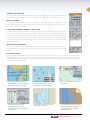
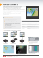
PROFESSIONAL SERIES Simrad Navigation Systems ECDIS, PLECDIS, ECS and GPS WWW.SIMRAD-YACHTING.COM/PROFESSIONAL 2 Simrad Professional Navigation Systems SIMRAD PROFESSIONAL The Simrad Professional portfolio offers a comprehensive range of marine electronic products spanning instruments, autosteering, gyro compasses, navigation systems, radar, communications and safety. Simrad Professional products are synonymous with sophistication and rugged reliability, providing tried and trusted solutions for a wide range of professional applications. With more than 60 years experience of developing quality products, Simrad are well positioned to meet the needs of today’s professional mariners. S I M R A D P R O F E S S I O N A L N A V I G AT I O N S Y S T E M S Simrad professional products include a wide range of sophisticated, approved navigation systems, electronic chart systems and echo sounders to ensure optimal safety and performance. Simrad navigation systems are built on years of experience within steering, charting, navigation and safety. Already in 1985 Simrad collaborated with the Norwegian Hydrographic Office to develop a pre-ECDIS standard charting system. The CS68 ECDIS has been built on this 20-year charting history and developed in close cooperation with shipping companies and high speed craft navigators. The new NSE seriesis tailor made for smaller high speed boats, coasters and Fishing vessels. Professional Series Navigation Systems Simrad CS68 ECDIS 3 The most reliable ECDIS (Electronic Chart Display and Information System) in the world. With the CS68 ECDIS system, we are the only ECDIS supplier in the world that offers an approved ECDIS that runs on 24VDC. This makes the CS68 also very suited for smaller vessels under 3000 tons. with quick access to the most important functions. We have also created a unique voice alarm system, which makes it possible to separate ECDIS alarms from other alarms on the bridge. The Simrad CS68 ECDIS and P LECDIS systems are developed in Norway for use under the roughest conditions. The system is also approved by DNV for use on all SOLAS ships and other vessels that must carry an ECDIS system. A cost saving ECS version for use on board vessels that want ECDIS functionalities, but are not required to carry a full ECDIS system onboard, is also available. C S 6 8 K ey F eat u res Hardware and software are type approved according to CS68 ECDIS 23inch the IMO and the Marine Equipment Directive (Wheelmark) United States Coast Guard USCG approval pending. ENC/S57, S63 and C-map SENC CM93/3 support Part Number Description 000-00018-001 CS68 ECDIS system, 24 V DC system without monitor 000-00018-003 CS68 ECDIS system, 24 V DC system with monitor 000-00044-001 Radar overlay kit Double trip counter 26053231 COP10-CS6x Remote operator panel SIMRAD Backup Manager 26053355 COP20 Operator panel designed for mounting in the chair’s armrest 26053207 COP30 Illuminated keyboard and mouse for all CS chart systems. 26056713 ECDIS external ON/OFF switch Chart update online or through CD/DVD/USB flash drive. Dynamic chart licensing. Radar overlay option AIS Class-A and Class-B support. AIS filter and two way communication Relay interface to ship’s main alarm centre. Dual monitor output 19”, 20.1”, 23” or 27” Wide approved ECDIS displays Optional remote control COP20 Optional remote control COP10 COP10 mounted in the armrest of the chair. Professional Series Navigation Systems 4 Simrad PLECDIS TM Simrad Paperless ECDIS solution. One of the main features of ECDIS is to be able to go p aperless, using high quality ENCs (Electronic Navigational Charts) for safer navigation. Combining a CS68 ECDIS system with backup (Simrad PLECDIS™). The navigator can utilize a fully approved and redundant high class electronic navigation system that allows the ship to operate without paper charts on board. This provides crew and owners benefits in safety, cost and efficiency, and enables automatic updates of charts everywhere. ECDIS / PLECDIS TM K ey F eat u res Seamless zooming Quick route function Preferred turn rate in every turn Head up display True Route Navigation Logbook with voyage play back AIS and ARPA target overlay Automatic chart scale Vessel shown in actual size Ship’s turning radius shown in route planning Tide calculation CS68 ECDIS 27 inch Wide Screen Fast vessel update rate Quick level change of chartclutter Variable range and bearing line Tracking of other vessels Man Over Board function Unique tracking feature MC50 Marine Computer The CS68 type approval fulfills the requirements to sail “paperless”. Professional Series Navigation Systems Shock absorbers ensure optimal performance. Part Number Description 000-00018-004 CS68 PLECDIS system, 24 V DC system without monitors 000-00018-002 CS68 PLECDIS system, 24 V DC system with monitors 000-00044-001 Radar overlay kit 26053231 COP10-CS6x Remote operator panel 26053355 COP20 Operator panel designed for mounting in the chair’s armrest 26053207 COP30 Illuminated keyboard and mouse for all CS chart systems. 5 O perational modes The Simrad CS60 series ECDIS/ECS systems have the unique capability of combining both a monitoring and a planning mode. All safety functions are continuously monitored even when route planning. M onitor mode In monitoring mode, the position of the vessel is displayed in real time on the chart. The ship’s outline and size is displayed with actual vessel heading, a COG and SOG vector and actual track. The vessel can be displayed in relative or true motion. H igh performance marine comp u ters All Simrad Marine Computers are made to serve the demands of the professional marine industry and are not on the shelves industry PCs which are used by most other manufacturers. Simrad believes that a vessel’s primary navigation system deserves better. The computers are type approved a ccording to IEC 60945 and the chart systems carry a 2 year warranty to back it up. All systems come standard with a total s ystem recovery feature, so in a case of breakdown the system can be restored to its p revious state a fter repairs have been performed. A R P A radar interface By activating the interface to an ARPA radar, moving targets and operator s elected “fixed points“ can be displayed. Other vessels are then shown in real time on the chart, color coded depending on possibility for collision. P lanning mode Planning of a route and the definition of waypoints is very simple using e ither a trackball or numeric keyboard. A pan function enables the operator to move around in the chart. To view any position in the world, the “Pan To” function can be used for viewing the chart in a specific position in Latitude, Longitude or around the vessel’s own p osition or a waypoint. Planned routes can be stored and recalled whenever necessary. Zooming in the chart may be performed in numerous ways. Also as a defined zoom area. An Antigrounding feature, detecting o bstacles in the chart, may be set to meet user requirements. Fixed range markers are available to ease and secure navigation in narrow waters. AIS targets are shown in real time and in real size. Menu bar with icons and large characters. The only ECDIS with voice warnings to separate the alarms from the swarm of other constant beeping buzzers. Professional Series Navigation Systems 6 Simrad CS66 ECS Flexible ECS System with ECDIS software. Simrad is not only offering approved ECDIS systems (Electronic Chart Display and Information System) for professional users, as professional solutions are also provided by the CS66 for smaller vessels including harbour vessels and yachts. The Simrad ECS systems come with the same professional core software as our ECDIS, as well as industry grade professional computers. The flexibility around space available and monitor type and size is bigger with an ECS system than with an ECDIS. We cover the complete range of screens from 10” to 23” Wide for commercial v essels. C S 6 6 K ey F eat u res Hardware approved to IEC 60945 standard CS66 ECS 19inch Software complies with ECDIS standard Advanced route planning not found in regular chart plotters Flexible storage of tracks, symbols, objects and log files Advanced sensor filters Anti grounding system Short way to coming regulatory ECDIS Very low life cycle cost Part Number Description 000-00017-001 CS66, 8 channel, 24 V DC system without monitor. Parts included: MC50 MKII Marine computer 000-00044-001 Radar overlay kit 26053231 COP10-CS6x Remote operator panel 26053355 COP20 Operator panel designed for mounting in the chair’s armrest 26053207 COP30 Illuminated keyboard and mouse for all CS chart systems. A wide range of navigation systems Hook your ECDIS/ECS up to the internet CS68 ECDIS CS68 PLECDIS Two modes of quick and easy route planning. TM CS66 ECS Several display pallets available, night pallet with filled light sectors shown here. Professional Series Navigation Systems and download Notice to Mariners wherever you are (depending on user defined service provider) Always up to date tide tables . electronic chart systems : cs 6 8 ecdis 7 MC50 marine computer Marine colour monitor FB200 filter box Chart interface unit Cherry keyboard Logitech TrackMan® wheel Splitter cable for TrackMan wheel and keyboard Loudspeaker Alarm reset unit electronic chart systems : P L ecdis 2 x MC50 marine computers 2 x Colour monitors (19”, 20.1”, 23” or 27”) 2 x FB200 filter boxes 2 x Chart interface units 2 x Cherry keyboards 2 x Logitech TrackMan® wheels 2 x Loudspeakers 2 x Alarm reset units 1 x 10 m crossed network cable 1 x PLECDIS™ plaque Professional Series Navigation Systems 8 NEW All-in-one ECS Simrad NSE For sophisticated performance in network applications; the new NSE provides 8” and 12” display options and offers the ultimate compact Patrol / Navigation tool for smaller vessels and tenders. Rotary controller: Perfectly intuitive for fine or course control of gain, zoom and menu with push to enter functionality Alphanumeric keypad Quickly enter waypoint, route and track information with precision USB and Flash Drive Record under water surveillance, screen scots, camera images directly to the medium of your choice for report files Programmable QuickTouch keys Touch a button and make things happen... S I M R A D N S E F eat u res Lightning Fast, All-in-one Chartplotter Elegant Design, Brutally Strong Simrad Construction Radar, Chart, Sonar, Autopilot controller, CCTV monitor, Instrument monitoring / The high power processing of NSE lets you zoom, pan and navigate with virtually zero chart lag time Classic Simrad design with flush mount option compliments any helm design 2D, 3D and shaded relief capability presentation modes robust bracket mount all designed for harsh environments All New Simrad High Performance GS15 GPS 5Hz Antenna with NMEA2000/SimNet connections Award Winning Echosounder and Radar Technology BSM-1 Broadband Sonar for excellent target separation and deep water penetration BR24 Broadband Radar & HD Digital Domes and Arrays for superior image clarity and definition New Simrad NSE Control Interface for Easy Operation Rotary Controller, Cursor Pad, and an Alphanumeric Keypad for flexible & solid input control Substantial aluminium housing, waterproof connections, and a Complete Flexibility – with “Masterless” Networking Share Charting, Echosounder and Radar information across multiple units “Masterless” system - Any networked unit can operate independently. Network switch may be required SimNet plug and play data networking for NMEA2000 compatible sensors & Instrumentation Video input and output for display of video or navigation data where you want it Brilliant, Low Power LED Display Technology QuickTouch for quick and easy page access and recall A “no compromise”, brightest in class SunView™ LED Display Minimal time required to learn operation with on-screen menus and prompts 100% night time dimmable back lighting NSE12 is industry first 12” MFD with high resolution XGA display Large readable fonts for clear visibility Part Number Description Part Number Description AA010145 NSE8 Multifunction Display (ROW Version) 000-0125-25 GS15 Antenna with 4m Micro-C to SimNet Cable AA010147 NSE12 Multifunction Display (ROW Version) 000-0132-031 NEP-1 Five port ethernet expansion port. Professional Series Navigation Systems inte G R AT E E V E R Y T H I N G 9 AIS Autopilot Broadband SounderTM High Speed GPS NMEA 2000 Data HD Digital Radars Broadband RadarTM TM SIRIUS® Marine Weather Digital Switching Video StructurescanTM Sonar Imaging direct access to feat u res with the press of a b u tton Emphasis is on “clear and easy to read”. The position and steer screen offer concise information displayed in large fonts and simple graphics. The Pages utility is Command Central for frequently used options and tools. Display and edit waypoints, routes and tracks as well as saved log files. AIS, Alarms and GPS status pages are easily accessed. Pre-configured gauge displays show vessel, environmental and navigation information in digital, analogue or bar format. Optional video inputs complete your NSE system. AIS SimNet & N2K Video Integrate with Simrad AI50 or NAIS-300 Class B AIS Systems to see and be seen. Overlay AIS-equipped vessel information on chart and radar displays. SimNet makes data sharing and system control easier and more flexible than ever before. Integrate Simrad autopilot, instruments, VHFs, sensors or any NMEA2000 engine or device to the intelligent SimNet backbone. Simrad NSE has both video input and video output capability. Two video inputs are available with the included RCA/NMEA cable.Output your Simrad NSE to any remote display or large screen via DVI connection port. Professional Series Navigation Systems 10 direct access to feat u res with the press of a b u tton Combine charting, pilot and vessel pages for unprecedented vessel control Premium Charts Embedded A u topilot • Award-winning Navionics Charts include seamless chart detail, satellite photos and 3D NSE 2.0 software combines the world’s best performing autopilot system with brilliant, Best in Class NSE displays. Simply network an • View depths and elevations in 3-dimensions, with optional satellite photo overlay NSE8 or NSE12 display with a Simrad autopilot system and get full autopilot functionality, with or without an autopilot control display. Engineered to benefit both “space-challenged” dash layouts and • Port Services & Points of Interest. Detailed information, including phone numbers, for services and points-of-interest. multi-station expanded systems, NSE 2.0 autopilot integration offers tremendous flexibility. Fully control your Simrad Autopilot from an NSE8 or NSE12 display Upgrade to Navionics Platinum Plus™ Alter course with the Rotary Controller or Cursor Pad Dedicated Standby / Auto key and Pilot Status indicators allow safe, easy Pilot operation The NSE performs all the functions of an AP24 or AP28 The NSE can replace or work together with an autopilot controller Fully configure the Autopilot from the NSE display TM GS15 High Speed GPS Antenna digital switching • Advanced 5Hz performance with a true update rate of 5 times per second for best in class position data during acceleration and high speed manoeuvres • The Simrad GS15 works with SimNet and NMEA 2000® networks for enhanced location accuracy and improved satellite-signal fix NSE 2.0 breaks new ground with support for CzoneTM digital switching from BEP Marine. CzoneTM digital switching offers a new paradigm for cost effective, control and monitoring of nearly any system on virtually any vessel. The Simrad NSE can operate as a GS15 • WAAS and EGNOS Professional Series Navigation Systems CzoneTM controller. Control your lights, turn on your bilge pump, monitor tank levels – all from your NSE navigation system. NSE and CzoneTM – a partnership in Innovation. Find out more from www.bepmarine.com 11 True Motion Radar Radar improves a mariner’s situational awareness. Easy to operate Radar function allows for Navigation, Target Tracking and collision avoidance. Display both MARPA and AIS targets for the complete picture. B roadband R adar tm Simrad HD Digital Radars and the award-winning Broadband Radar™ now support True Motion Radar Display. Moving vessels are instantly distinguished from fixed objects and land masses, eliminating guesswork in PPI interpretation. Broadband Radar near-range performance and usability is optimized with the addition of High-Speed Antenna Rotation; increased target update rates provide early detection and tracking of high-speed radar targets. Discover also the capability to show MARPA targets on your chart screen and added floating VRM’s and EBL’s for more effective radar piloting. Simrad NSE delivers “big-ship” radar features to your vessel. Vessel Course Extension Line. Vector showing predicted vessel position based on time or distance Trackback™ SideScan™ DownScan™ NSE utilises high performance Broadband Sounder™ technology to penetrate deepwater, clearly define underwater structure and “whisper” into the water to find more fish. STRUCTURESCAN™ StuctureScan™ is plug and play technology allowing quick and clean installation for up to three NSE displays per transducer. You’ve never seen bottom structure like it - moorings, wrecks and other structures, on or part of the bottom, will be reveled instantly. Search for missing people and/or other objects is significantly easier with Simrad StructureScanTM. SideScan: Full-screen, top-down panoramic view of highly detailed bottom imaging on either side of the boat DownScan Imaging™: Adds a new dimension to echosounding. High Frequency imaging gives life-like representation of water structure TrackBack™: Scroll back simultaniously through sonar history and chartplotter trail from sonar or StructureScanTM display to easily mark waypoints DownScan™ Overlay™: Exclusive new technology overlays DownScanTM onto Broadband SounderTM on one display that clearly separates fish targets from surrounding structure Professional Series Navigation Systems 12 Simrad BR24 Broadband Radar™ Simrad has introduced a revolutionary new radar system unlike anything else on the boating market. Utilising broadband Frequency Modulated Continuous Wave (FMCW), this breakthrough technology provides superior target detection and separation, ease of operation and a new level of navigational safety to a wide range of boats. broadband radar tm K ey F eat u res Crystal clear image: Miss none of your immediate surroundings. Fantastic for tight manoeuvres in tight/crowded areas or in conditions of limited visibility. Unparalleled performance in heavy snow conditions. InstantOn™: Solid-state technology produces an immediate, accurate on-screen image. Low power consumption: Broadband radar requires very little power: ideal for all types and sizes of boat. BR24 Broadband RadarTM Extremely low emissions: This safest of radars means it can be mounted anywhere. Broadband radar has lower emissions than a mobile phone. Quick installation: No reason to open the dome, no tune or zero mile adjustment, and best of all – no radarlicensed technician required. Very low life cycle cost - no maintenance required Part Number Description 700-2007 BR24 Radar bundle for Simrad NSE series Includes Scanner, scanner cable 20 m (65.5 ft), RI10 interface box, Yellow ethernet cable - 1.8 m (6 ft) A chieve amazing target definition with S imrad B R 2 4 B roadband R adar ™ Four posts to starboard with two yachts clearly visible behind Only possible at this range as broadband radar has no main pulse suppression that a conventional radar suffers from. Possible to see targets close together and yet they are clearly shown as separate targets. Vacant berths in a marina are easily identified At short ranges the Broadband Radar is showing up the individual yachts in their berths, ideal at night when visibility may be compromised. In this type of situation conventional radar would only show a merged target possibly obscured by the main pulse. R ange discrimination performance Range discrimination is a measure of the radar’s ability to distinguish closely spaced targets on the sample bearing. FMCW technology provides unsurpassed performance for your maximum safety and precise navigation. At 16nm and less the BR24 has from 1X to 5X more the range discrimination ability to see those smaller targets than conventional 2kW pulse radars. This greatly improves your situational awareness. Professional Series Navigation Systems At 16nm and less the BR24 has from 1X to 5X more the range discrimination ability to see those smaller targets than conventional 2kW pulse radars. HD Digital Radar 2kW / 4kW / 6kW / 10kW / 25kW Simrad HD Digital Radar Systems use both Radomes and Open Array antennae, working with power levels from 2kW to 25kW via high capacity Ethernet. They ensure exceptional detection of small or distant targets using advanced Digital Signal Processing (DSP). Screen-clutter in any weather is virtually eliminated to display the full picture of your surroundings allowing a clear, accurate and easy-to-interpret image, using 10-bit digital radar video sampling and Sensitivity Time Control (STC). Adding a high speed heading input from an autopilot system or dedicated sensor allows the radar image and MARPA-targets to be accurately overlaid on the chart. Enhanced rotational mode enables you to interpret targets instantly. Simrad Professional’s HD Digital radars automatically adjust colour gradients on longer ranges for better interpretation of targets. This is especially useful when looking into storm areas and weather fronts. Automatic Harbour and Offshore modes provide optimised radar imaging for hands-off operation. The radar provides bearing and distance, speed and course, closest point of approach and time on selected targets. Easy to use Guard Zone areas can be shaped and defined by the user, to maintain a radar watch in specific zones. Qualified radar targets that enter the active zone will trigger an alert on the radar system. 13 Simrad 6kW Array Simrad 4kW Dome Part Number Description AA010028SIM 25 kW Radar scanner, 7 ft AA010016 Navico 25kW radar processor AA010027SIM 10 kW Radar scanner, 6 ft AA010015 Navico 10kW radar processor AA010026SIM 6 kW Radar scanner with 4 ft antenna and 20 m (66ft) cable Automatic Tune, Gain and Sea Clutter Adjustments AA010014 Navico 6kW radar processor Resolution 1280 x 1024 pixels AA010025SIM 4kW radome, 24 In, with 15 m (49 ft) cable Wide dynamic range receiver for improved sea clutter AA010013 Navico 4kW radar processor Modern remote keypad controller AA010024SIM 2kW radome, 18 In, with 15 m (49 ft) cable Digital, Analog, and multimedia inputs AA010012 Navico 2kW radar processor H D D igital radars K ey F eat u res High Performance Scanners Networked Radar System Digital Signal Processing Technology Radar/Chart Overlay FIVE Scanner Options From: 2 kW/18” to 25 kW/7’ VGA output connector for second monitor Nav lines and trails with parallel index lines 72 18 mi Optional tracking up to 50 AIS targets Optional Target Tracking (ATA) up to 10 user Selected targets - up to 5 automatic Optional Gyro Log interface Targets can be interpreted instantly through chart information – such as navigation aids and coastlines. Heading allows Mini-ARPA operation on NSE with tracking capacity up to 10 different User-defined targets. Different colour palettes are provided to suit the user’s taste as well as to improve viewing in different lighting conditions. Professional Series Navigation Systems 14 Simrad Automatic Identification Systems Smaller boats can easily go undetected by radar systems on larger commercial vessels, because the radar’s line-of-sight can be blocked by the superstructure of the ship or can also miss the boat due to the high placement of the radar antenna. This can easily exceed 30 meters over the sea level. The AIS is not line-of-sight and the range is typically about 20 nautical miles. This is one major reason why large commercial vessels are required to carry an AIS-transponder. AIS focuses your awareness on all vessels in your vicinity and helps reduce the risk of collision by exchanging safety data between them, such as: Vessel Name, Size & Call sign - Maritime Mobile Service Identity number (MMSI), Vessel Type, Time to closest point of approach, Course, Speed and Heading. Simrad is currently the only major brand that offers NMEA2000/SimNet compatible Class-B Transmit and Receive AIS transponder systems, both as an integrated standalone product with colour display (AI50) and as a black box solution (NAIS-300) designed for use with any AIS-compatible multi-function display product. Ai50 A i 5 0 K ey F eat u res Class-B AIS transponder with integrated GPS receiver and 4” TFT colour display Backlit display and keypad Built-in map with range rings and 12 zoom ranges from 0.01 to 32 nm Cursor ID mode allows easy readout of target vessel data Target track log mode data stored and played back via SD-Card AI50 Call Target. Simply place the cursor over the target you wish to contact and press the DSC button* Part Number Description * Note: This feature requires that the AI50 is connected to a Simrad RS80 series VHF radio. 000-0135-00 AI50 AIS Class B transponder 000-0135-03 NAIS-300N Class B AIS with SimNet interface 000-0135-04 NAIS-300L Class-B AIS with NMEA 2000® interface Favourite list with “Fleet tracking” . Audible/Visual alarms for Collision, Lost vessel track, Favourite buddy alarm and Guard Zone NMEA2000/SimNet/RS232 Interface nais - 3 0 0 N / L The NAIS-300 is a Class-B AIS black box transponder system with an integrated GPS receiver. It comes in two versions; the L-version with the NMEA2000 Interface and the N-version with the SimNet Interface. A CD-ROM and a RS232 PC cable are included for entering the MMSI number and other vessel data. N A I S - 3 0 0 K ey F eat u res Black Box Class-B AIS Transponder System with integrated GPS receiver NMEA-2000/SimNet/NMEA-0183 (high Speed) Interface AIS Transmit & Receive function (AIS Class-B) Move the cursor over a target to identify the vessel Set a guard zone for a target Professional Series Navigation Systems NAIS-300 Range rings make it easy to judge distance to any target See when your colleagues / sister ships in the area and get notified when they enter your AIS range 15 A I S mx 5 3 5 A MX535A / MX512 AIS System: Type Approved AIS Transponder System, meets the latest IMO requirement ITU-RU.1371-3 standard. MX Marine has developed a complete solution to D/GPS and AIS System. With only one combined Control and Display unit, you can access all related information and still command full control of all D/GPS, AIS, and optional D/GPS Compass functions. The system connects directly to the ship’s navigation sensors as well as ECDIS, ARPA radar and other shipboard information systems. Adding AIS to navigation for spontaneous ‘ship to ship’ or ‘ship to shore’ recognition greatly enhances safety at sea and provides mariners with new levels of real-time information. Designed with the deep sea commercial mariner in mind, we have created multiple configurations to suit the size and complexity of any vessel. The MX535A transponder, is a fully IMO-compliant STDMA unit remotely controlled by MX512 Control and Display unit. Transponder system setups and controls is configured in the MX512. It can also gather the ship’s sensor data and organizes the information for transmission via AIS. The ship’s ECDIS, ARPA and Pilot’s PC all have access to both the D/GPS and the AIS information via the high-speed serial ports of the MX535/ MX512. Password protected menus allow you to safely and simply enter all Static and Voyage related AIS information. AIS Situation Displays give you immediate and continuous graphic and/or text information about AISequipped ships and shore stations as they come into radio range. MX535A Part Number Description 000-10037-001 MX535A 512-100-1001 MX512 junction box 512-000-0000 MX512 CDU mx 5 3 5 A K ey F eat u res Complies with the latest IMO standard ITU-RM.1371-3 Identify other AIS enabled ships by its’ correlated UAIS identification Contact other ships using the Call Signs presented by the AIS Screen MX512 AIS/MKD and Navigation Control Display Receive an instant overview of traffic situations and the maneuvers of other ship Able to get detailed information on AIS enabled ships in radar blind zones Supplied Junction Box allows easy interconnection between MX535A, MX512 Display and other interfaces Built-in GPS is RAIM enabled MX512 Junction Box Professional Series Navigation Systems 16 Navigation System MX500 I M O T ype - approved C ompact N avigator The MX500 DGPS Navigation Control and Display Unit meet the latest IMO Specification It is a type approved marine navigator with the MX521A, MX421 or MX525A DGPS Antenna Sensors, including RAIM (Receiver Autonomous Integrity Monitoring). MX500 can also be used with MX575A DGPS Compass. MX575A is typed approved for primary Navigation and secondary heading. Also, the MX500 can be used as a Single Station or in Dual-Control mode with up to four slaves via high-speed LAN interface. M X 5 0 0 K ey F eat u res Network to Integrated Bridge Systems (IBS) or to other conventional equipment via LAN or NMEA serial ports. Save & restore Waypoints, Routes, Plot and Configuration settings via USB or built-in Flash RAM. Convenient software updates via USB port. Multiple options for navigation data management via LAN, USB, or NMEA serial ports. User-friendly man-machine interface based on its renowned predecessors. MX500 D/GPS Navigation Control Display Integrity monitoring of dual DGPS systems for automated redundancy and reliability (BRIM). Installation Manual Mechanical Installation User selectable NMEA0183 messagesand V1.5 to V2.3 forDrawings backward compatibility with the widest range of devices. Multi-port interface that can be connected to ECDIS, MX 500 NAVIGATION RTE WPT NAV ARPA, Gyro SYSTEM and other navigation information systems. 1 2 3 ABC DEF GHI 4 5 JKL 7 POS STU EDIT GOTO MNO 8 0 CFG PQR 9 D/GPS VWX 6 AUX AIS YZ CLR 102.00 mm PLOT Part Number DescriptionUSB 500-01-00 MX500 CDU with MX521A GPS Antenna (add cable) 500-03-00 MX500 CDU with MX521A DGPS Antenna (add cable) 198.00 mm MX-500 MX-500 CDU O ptional accessories MOB 500-100-1002 MX500/MX510 Junction Box Figure 3.1 MX500 Display Console Dimensions (Front View) MX500 Junction Box Grounding Stud Power/ Data Connector (12-Pin Male) Antenna Connector (10-Pin Male) Auxiliary Connector (8-Pin Male) LAN Connector (RJ-45) MX500 Configuration Figure 3.2 Connector MX 500 Connector Configuration (Rear View) Professional Series Navigation Systems Navigation System MX510 and MX512 17 T he latest in I M O compliant navigation systems The MX510 and MX512 models are designed to be used as IMO compliant navigation systems, in conjunction with MX DGPS smart antennas and DGPS compasses, on board workboats, ferries, fishing boats and other commercial vessels. The MX510 and MX512 are easy to use via the user-friendly MMI (Man Machine Interface) already renowned from its predecessors; these versatile navigation systems offer extraordinary capabilities, with its multi-port interface that can be connected to ECDIS, ARPA, Gyro and other navigation information systems. It can be configured as a single display or multi-unit redundant displays. The MX510 and MX512 with the MX521A smart antenna are type-approved marine navigator. Backward compatible with MX421B-10 DGPS antenna. They are also Compatible with MX575 DGPS Compass. MX510 The MX510 with the MX521A DGPS is a type-approved marine navigator. Backward compatible with MX421B-10 sub-meter DGPS antenna. It is also compatible with MX575 D/GPS Compass. Features two independant RS-422 NMEA ports. Part Number Description 510-01-00 MX510 CDU with MX521A GPS Antenna (add cable) 510-03-00 MX510 CDU with MX521A DGPS Antenna (add cable) 510-000-0000 MX510 CDU 500-100-1002 MX500/MX510 Junction Box MX510 Navigation Control Display MX512 The MX512 features eight independent RS-422 and one RS-232 serial ports for two-way communication with any NMEA 0183 compatible device. Optional software updates are made through the convenient USB ports. Part Number Description 512-01-JB MX512 CDU with MX521A GPS Antenna and JB (add cable) 512-03-JB MX512 CDU with MX521A DGPS Antenna and JB (add cable) 512-000-0000 MX512 CDU (also order JB P/N 512-100-1001) 512-100-1001 MX512 Junction Box MX512 Navigation Control Display M X 5 1 0 / M X 5 1 2 K ey F eat u res IMO Type-Approved with RAIM enabled Choice to save and restore Waypoints, Routes and M X 5 1 2 O ptional accessories Configuration settings . Multiple navigation data management options using LAN, USB or NMEA serial ports High speed LAN interface for Master/Slave operation (with Integrity Monitoring) and up to 4 slave displays Convenient navigation equipment interface using LAN or NMEA ports MX512 only: 9 independent serial data ports and one VGA port MX512 Junction Box • • • Professional Series Navigation Systems • • 18 MX Smart Antennas Navigation authorities around the world have installed DGPS radiobeacon networks that broadcast free RTCM correction information. With the use of its’ built-in beacon demodulator, the MX smart antennas use these real-time corrections to deliver accurate, reliable positioning when in range of a beacon transmitter. The antennas can be controlled by the operator to accept RTCM data from external sources using the MX Control and Display Unit (MX CDU). Receiver Autonomous Integrity Monitoring (RAIM) is a safety feature in the MX smart antennas which continuously verify the integrity of the GPS system to ascertain its’ accuracy and reliability. When position error exceeds a pre-set limit, the MX CDU alerts the operator to take precautionary measures. RAIM is one of the latest requirements under IMO MSC 112 (73) regulation. This RAIM feature can be accessed by the operator using the MX CDU. The MX smart antennas can interface directly to the MX CDU or to other NMEA0183 compatible devices. M X smart antennas F eat u res IMO type approved smart antennas RAIM enabled Compatible with all MX CDUs MX521A/MX525A WAAS compatible MX Control and Display Unit M X 5 2 5 A D G P S S ensor with M X B 5 Precision DGPS positioning solution in a black box unit. Featuring built-in RAIM and Space Based Augmentation Systems (SBAS) and compliant to the latest IMO standards GPS/DGPS Black-box Receiver. The MX525A delivers position accuracy better than 1 meter in DGPS mode when using RTCM correction data. It also provides better than 5 meters accuracy in standard GPS mode. It is backward compatible with existing MX420 systems to make them compliant with the latest IMO requirements. Space Based Augmentation Systems (SBAS) like the European Geostationary Navigation Overlay System (EGNOS), the US Wide Area Augmentation Service (WAAS) and the Japanese MTSAT Satellite Based Augmentation System (MSAS) are being developed throughout the world. The MX525A can be controlled to use these systems to provide accurate positions in areas not covered by DGPS beacon stations, but covered by SBAS. M X 5 2 5 A K ey F eat u res MX525A DGPS Sensor IMO MSC.112(73) compliant* RAIM (Receiver Autonomous Integrity Monitoring) enabled Meets Smart-Beacon specifications Suitable for installations with long cable requirements Compatible with existing MGL-3/4 combined antenna and coaxial cable Connects directly to MX Control and Display Unit MXB5 DGPS Antenna Better than 1 meter DGPS Position accuracy Better than 5 meter GPS Position accuracy Integrated DGPS system including beacon and SBAS (WAAS/EGNOS) NMEA0183 ver. 3.0 interface *MX CDU is required to comply as an IMO type approved system Professional Series Navigation Systems Part Number Description 727061 MX525A DGPS Smart Antenna Sensor 721755 MXB5 DGPS Antenna 9525-200-85000 MX525A DGPS Smart Sensor with MXB5 Antenna 19 M X 4 2 1 B - 1 0 S mart A ntenna High accuracy DGPS Smart Antenna.This antenna has sub-meter accuracy with Beacon DGPS corrections. MX421B-10 is also offered with 5 Hz position output and is used in race boats because of high accuracy. The High Accuracy MX421B-10 delivers position accuracy better than 1 meter in DGPS mode when using RTCM correction data. It also provides better than 3 meters accuracy in standard GPS mode. The MX421B-10 is available in 1 Hz or 5 Hz position update. M X 4 2 1 B - 1 0 K ey F eat u res Better than 1 meter (RMS) DGPS Position accuracy and better than 3 meter (RMS) GPS Position accuracy NMEA0183 ver. 3.0 interface MX421B-10 Smart Antenna IMO type approved*, including RAIM (Receiver Autonomous Integrity Monitoring) Designed for easy upgrade of existing MX420 installations to latest IMO Standards. *MX CDU is required to comply as an IMO type approved system Part Number Description 9525-200-80110 MX421B-10 DGPS Smart Antenna 1 Hz 9525-200-78610 MX421B-10 DGPS Smart Antenna 5 Hz M X 5 2 1 A S mart A ntenna Precision D/GPS positioning solution in a Smart Antenna unit.Featuring built-in RAIM and Space Based Augmentation Systems (SBAS) and compliant to the latest IMO standards. DGPS Smart Antenna Receiver.The MX521A delivers position accuracy better than 1 meter in DGPS mode when using RTCM correction data. It also provides better than 5 meters accuracy in standard GPS mode. It is backward compatible with existing MX420 systems to make them compliant with the latest IMO requirements. Space-Based Augmentation Systems (SBAS) like the European Geostationary Navigation Overlay System (EGNOS), the US Wide Area Augmentation Service (WAAS) and the Japanese MTSAT Satellite-based Augmentation System (MSAS) are being developed throughout the world. The MX521A can be controlled to use these systems to provide accurate positions in areas not covered by DGPS beacon stations. M X 5 2 1 A K ey F eat u res IMO MSC.112(73) compliant* RAIM (Receiver Autonomous Integrity Monitoring) enabled Meets Smart-Beacon specifications Designed for easy upgrade of existing MX420 installations to latest IMO standards Connects directly to MX Control and Display Unit MX521A Smart Antenna Better than 1 meter DGPS Position accuracy Better than 5 meter GPS Position accuracy Built-in DGPS sources include beacon and SBAS (WAAS, EGNOS, MTSAT) NMEA0183 ver. 3.0 interface *MX CDU is required to comply as an IMO type approved system Part Number Description 727050 MX521A GPS Smart Antenna 727051 MX521A DGPS Smart Antenna Professional Series Navigation Systems 20 MX575A DGPS Compass The MX575A D/GPS compass is designed to provide the Simrad Professional Autopilots, MX5XX Series navigation and AIS systems with reliable heading, ROT (Rate of Turn) and position information. The MX575A delivers a heading accuracy of better than 0.5° at update rates of up to 10 Hz. It also provides sub-meter DGPS positioning accuracy at rates of up to 10 Hz when using RTCM correction data supplied from internal beacon demodulator. MX575A DGPS Compass To augment the GPS-derived heading, the MX575A includes other supplemental devices. The combination of inclinometer and magnetic sensing devices aid the rate at which a heading solution is computed on startup and also speeds up reacquisition. A rate gyro provides a secondary source of heading data in times when the GPS heading is not available due to temporary obstructions. These sensors improve performance and increase dependability of the MX575A. The MX575A features two independent RS-232 serial ports and one RS-422 port. The output of the RS-422 port mirrors that of one RS-232 port. It also features COAST™ technology that allows it to use old correction data for up to 40 minutes without seriously affecting positioning performance. This feature offers peace of mind and allows you to focus on more important issues than reliability of a differential signal. M X 5 7 5 A K ey F eat u res Part Number Description 9525-200-80900 MX575A DGPS Compass with 15M Cable Type-Approved as a Transmitting Heading Device (THD) and a Primary Positioning Device Compatible with MX5XX family of CDUs Stand-alone automatic operation Heading accuracy of 0.5° Position and Heading updates up to 10 Hz Integrated DGPS sources including WAAS, EGNOS, and Beacon M X 5 7 5 A basic S ystem Sub-meter DGPS accuracy Fast start-up times MX500 Series Head Unit Sustained tracking during Rates of Turn up to 90º/s Sealed enclosure with IP 67 rating AT10HD Converter NMEA 0183 V3.0 interface with provision for UP external RTCM SC-104 corrections SimNet SimNet White Brown Yellow Green MX575A DGPS Compass MX500 Series Junction Box Rx+, A Rx-, B Tx+, A Tx-, B SimNet NMEA 0183 Professional Series Navigation Systems From NMEA "Talker" To NMEA "Listener" 5 This document is the property of Hatteland Display AS. This document and any authorized reproduction thereof, must not be used in any way against the interest of Hatteland Display AS. Any authorized reproduction, in whole or in part, must include this legend. D 6 D FRONT VIEW 483 mm (19,02”) F RONT VIEW 465mm (18,31”) 9 14mm 14mm (0,55”) (0,55”) 438,00 17,24 H H SALES DRAWING JH 19T14 MMD (16.8”) depth G 3 5 5 4 13,50 0,53 86.5 mm (3.40”) 4 13,5 64,26 2,53 Optional holes Ø6,5[0,26] screwed from the backside of pane 4 places horizontally Optional holes Ø6,5[0,26] screwed from the backside o 4 places horizontally Metric tread M6 or Ø6,5[0,26] 4 places vertically Metric tread M6 or Ø6,5[0,2 4 places vertically 4,01 0,16 PANEL CUTOUT PANEL CUTOU 13,50 0,5365 mm (2.55”) 129,00 5,08 13,50 0,5 129 315.5 mm (12.40”) 5 U Date: 29-08-2008 6 5 8 7 6 13,5 129,00 5 129,00 5,08 ns E 1 2 4 129 13,50 0,5 7 9 8 9 Mechanical DesignerProjection: 7251 S S Mechanical DesignerProjection: Date: Display Hatteland AS 7251 29-08-2008 Åmsosen Su N-5578Hatteland Nedre Vats Display AS 10 Åmsosen 11 N-5578 Nedre Vats 10 1 (5.8”) 144 mm 2 129,00 5 13,50 0,53 C O P 1JH 0 19T14 R emote SALES DRAWING MMD control MA1-AABA, Multi Power model shown in this drawing, H SALES DRAWING JHfor 19T14 MMD models. but measurements generally apply all MMD-xxx-Axxx MA1-AABA, Multi Power model shown in this drawing, (2.9”) but apply for all3 MMD-xxx-Axxx models. 4 1 measurements generally 2 72 mm 1 3 3 84,74 3,34 2 2 84,74 3,34 DIMETRIC VIEW 1 DIMETRIC1 VIEW 68mm (2,68”) 68mm (2,68”) 427.5(17,09”) mm 434mm 129,00 5,08 MA1-AABA, Multi Power model shown inMMD this drawing, 129,00 5,08 SALES DRAWING JH 19T14 but measurements generally apply for all MA1-AABA, Multi Power model shown in MMD-xxx-Axxx this drawing, models. 13,50 0,53 111.3 mm (4.38”) 285.0 mm (11.22”) but measurements generally apply for all MMD-xxx-Axxx models. (7.7”) TOP VIEW 434mm (17,09”) TOP VIEW 68mm 68mm (2,68”) (2,68”) 438,00 17,24 6,99 0,28 412mm (16,22”) 16mm (0,63”) 16mm (0,63”) 434mm (17,09”) 221.0 mm (8.70”) F TOP VIEW TOP VIEW 434mm (17,09”) 212.0 mm (8.35”) 196 mm 363 mm (14.3”) 14mm (0,55”) 14mm (0,55”) E D D F F G G ns E 8 M C 5 0 marine comp u ter 1 BOTTOM VIEW BACK VIEW BOTTOM VIEW BACK VIEW 6,99 0,28 64,26 2,53 BOTTOM VIEW BOTTOM VIEW 412mm (16,22”) 267mm (10,51”) 98,75mm (3,89”) 267mm (10,51”) 98,75mm (3,89”) 444mm (17,48”) 444mm (17,48”) D HATTELAN Materia Aluminium 505 St-37 Alu/Zin Stainless Steel A We 10 B C 11 Shee PSM Inte (www.p SIDE VIEW E SIDE VIEW E 483 mm (19,02”) 465mm (18,31”) 10 8 7 The images of the LCD display are the property of Hatteland Display AS. These images and any authorized reproduction thereof, must not be used in any way against the interest of Hatteland Display AS. Any authorized reproduction, in whole or in part, must include this legend. A 9 8 7 4,01 0,16 4 2 L C D monitors ( 31 9 ” display ) 1 6 4,01 0,16 5 4 21 4,01 0,16 3 2 C C 98,75mm 98,75mm (3,89”) (3,89”) E C D I S and P L E C D I S ™ and ecs systems 1 This document is the property of Hatteland Display AS. This document and any authorized reproduction thereof, must not be used in any way against the interest of Hatteland Display AS. Any authorized reproduction, in whole or in part, must include this legend. 444mm 444mm (17,48”) (17,48”) Technical Specifications 267mm 267mm (10,51”) (10,51”) B B 53 mm (2”) depth Professional Series Navigation Systems 22 N S e 8 and N S e 1 2 specifications nse 8 nse 8 nse 1 2 nse 1 2 radar characteristics D isplay Type 8” Colour TFT LCD 12.1” Colour TFT Radar Compatibility Screen Size 8 inch diagonal viewing 12 inch diagonal area viewing area Screen Resolution 800 x 600 1024 x 768 Screen Brightness 1500 Nits 1500 Nits Contrast Ratio 850:1 600:1 Viewing Angle 60 Deg above and below normal axis with >75% Languages (31) Broadband: Simrad BR24; Simrad HD Digital Series 2kW to 25kW LCD Display Modes Head-up, Course-up*, North-up*, Relative Motion (*Heading input required) Echo Trail Intervals: 15 sec, 30 sec, 1 min, 3 min, Continuous. Clear Trails VRM/EBL’s 2: User Configurable interface nominal brightness > 100:1 Contrast Ratio LAN 3 Ports 10/100 Base 60 Deg Side to Side from normal axis with : > 75% Interface (NMEA 0183) Input: GLL, GGA, RMC, RMB, GSA, GSV, APB, BWC, Nominal brightness. 100:1 contrast ratio DBT, DPT, MTW, VLW, VHW, HDG English (UK), English (US), German, French, Spanish, Output: GGA, GLL, GSA, GSV, VTG, ZDA, AAM, APB, Italian, Portuguese, Croatian, Finnish, Icelandic, Dutch, BOD, BWC, BWR, RMC, RMB, XTE, DBT, DPT,MTW, Norwegian, Polish, Swedish, Slovenian, Russian, Ukrainian, Bulgarian VLW, VHW, HDG, MWV,TLL, TTM Interface (NMEA 2000) Input: 59904, 60928, 65285, 65292, 65293, 65303, Unit Dimensions 212.0 x 285.0 x 111.3 266.0 x 356.0 x 65305, 65323, 65325, 65480, 126208, 126992, without bracket/knobs mm 122.7 mm 126996, 127237, 127237, 127245, 127250, 8.35 x 11.22 x 4.38 in 10.47 x 14.01 x 127493, 127505, 127508, 128259, 128267, 4.83 in 128275, 129025, 129026, 129029, 129033, (H x W x D) mm Unit Dimensions 127251, 127257, 127258, 127488, 127489, without bracket/knobs (H x W x D) in Pack Dimensions (H x 129038, 129039, 129040, 129285, 129539, 129540, 129794, 129801, 129802, 130306, 220 x 300 x 390 mm 260 x 340 x 435 mm 8.66 x 11.81 x 15.35 10.24 x 13.39 x 130314, 130576, 130577, 130817, 130820, inches 17.13 in 130821, 130831, 130832, 130834, 130835, Pack Weight 6.3 kg/12.6 lbs 8.5 kg/17 lbs 130838, 130839, 130840, 130842, 130844, Case Pack Weight (2 12.7 kg/ 25.4 lbs 17.1 kg/ 34 lbs 130845, 130850, 130851, 130860 130310, 130310, 130311, 130312, 130313, W x L) mm Pack Dimensions (H x W x L) Inches Output: 59904, 60928, 61184, 65292, 65287, 65289, Per Case) 65290, 65293, 65303, 65305, 65323, 126208, mechanical Housing Construction Die Cast Aluminium Rear housing, Snap-fit front bezel Heat Sinking Direct heat transfer from processor to housing Screen Direct Bonded Processor/ RAM/ Hard 1.6 GHz / 512 MB / 80 GB 126996, 127237, 128259, 128267, 129285, 130577, 130818, 130819, 130831, 130835, 130836, 130837, 130839, 130840, 130844, Drive Interface Direct Access Keys (DAK’s), Alphanumeric Keypad, Rotary knob with Push-to-Enter plotter characteristics Display Modes Head-up, Course-up*, North-up*, Relative Motion (*Heading input required) Latitude Limit 83º North, 85º South Alarms Position, Off-Course, Waypoint Radius, Arrival, Anchor, Anchor Depth, Shallow, Deep, Water Temp Rate, Low Boat Speed, True Wind Shift, True Wind High, 130845, 130850, 130851 USB Port (2) - 1 Front, 1 Rear Video Output DVI-I x (1) Video Input Composite Video x (2) (multiplexed) Video Compatibility NTSC type N and 4.4.3, PAL type B, D, G, H, I, M, N User selectable SD Card Slot environment Temperature -15 Deg C to +55 Deg C (+5 Deg F to +131 Deg F) Waterproofing IPx6 P O wer True Wind Low, Guard Zone 1 & 2, Voltage Hi/Lo, Power supply 12.0 VDC-24.0 VDC (9.0 - 32.0 VDC Min-Max) Missing Data: Depth/Rudder/Wind/Heading/Weather, Current Draw (in 21.6W or 1.8A @ 12.0 VDC or 21.6W or 0.9A @ Weather: Lightning, Severe Weather, Storm, Weather Watts) at 24VDC Watchbox, Vessels: Dangerous, AIS Lost, Message, 12/24VDC Display only 33.6W or 2.8A @ 12.0 VDC or 33.6W or 1.4A @ MARPA Lost, MARPA Unavailable, Autopilot Alarms Cartography Single Embedded: Navico Insight HD US/Navionics Platinum Rest of World; Navionics Platinum Plus via SD Card Professional Series Navigation Systems 24VDC Certificates of Conformity CE(EN60945:2002)/CTick B R 2 4 s P E C I F I C AT I O N S 23 general Compliance R adar and A ntenna P arameters contd . FCC/IC/R&TTE/AUS Type Certification Transmitter peak power pending FCC ID: RAYBR24 Main Bang Dead Zone & IC ID: 4697A-BR24 Sea and Rain Clutter Limit – touch dome anywhere. Relative humidity: +35¡C, 95% RH Waterproof: IPx6 Sweep Time 1ms Sweep Bandwidth 65MHz max Horizontal Beam width (Tx Relative wind velocity 51 m/sec (Max:100 Knots) Power consumption Operating: 17W (Typ.) @ 13.8Vdc and Rx antenna) Vertical Beam width (Tx and Standby: 1.6W (Typ.) @ 13.8Vdc ~ Rx antenna) 110ma cable) Transmitter Source (preheating time ) Outside dimensions Weight (no cable) 5X less than a pulse radar Sweep Repetition Frequency 200Hz IEC60945 4th edition 2002-2008 Operating Temperature: -25¡ to +55¡C DC input (at end of radar None – not a pulse radar Tuning Human Exposure General Public Safety Environmental 100mW nominal output Side lobe level (Tx and Rx 9V to 31.2Vdc (12/24 Volt systems). Reverse polarity protection 5 Drawings No magnetron – Instant On™ antenna) Rotation Transmitter frequency Height 280mm x Diameter 488mm Scanner 7.4 kg Less than 6dB Com Protocol High Speed Ethernet and Serial dimensions NMEA2000/Simnet (with RI-10 Heading 1/32 to 24nm with 15 range settings (nm/sm/km) interface box) Inter Connecting cable 10m standard with RJ45 thin custom length connector – Display model dependent Maximum Inter Connecting 24 rpm +/- 10% cable length 36 rpm at less than 2nm range Bolts (4) X-band - 9.3 to 9.4Ghz 5 Drawings Plane of polarization Below -18dB (within ±10¡);Below -24dB C oms / C abling / M o u nting Transmitter source (warm-up No Magnetron – all solid state. Instant time) 30¡+/-20% (-3dB width) (outside ±10¡) Noise figure R adar and A ntenna P arameters Radar Ranges 5.2¡+/-10% (-3dB width) 30m M8x30 - 304 stainless steel W233mm (port/starboard) x L141.5mm Footprint On™ (matches Garmin GMR18HD/Raymarine RD218 footprint) Horizontal Polarization Scanner B R 2 4 dimensions Professional Series Navigation Systems Description Key A Cable entry area 24 h D digital radars s P E C I F I C AT I O N S Weight with antenna 25 kW 10 kW 6 kW 4 kW 2 kW 7’ / 2.2T5m 6’ /1.88m 4’ / 1.28m 2 4 ” / 6 2 0 mm 1 8 ” / 4 5 0 mm 54kg /119lbs 35kg /77lbs 29kg / 64lbs 10 kg / 22 lbs 4.2kg / 9lbs - no cable 6 kg / 13.2 lbs with cable Cable Length Dimensions 20 meters 20 meters standard standard 30 meters optional 30 meters optional 20 meters only 15 meter standard 15 meter standard 20 meters optional 20 meters optional 450 diameter L2254 x W458 x L1880 x W344 L1285 x W344 x 620 diameter H536 mm x H448 mm H448 mm x H280 mm x H227 mm L88.7 x W18.0 L74.0 x W13.5 L50.6 x W13.5 24.4 diameter 17.7 diameter x H21.1” x H17.6” x H17.6” x H11.0” x H8.9“ Max. Range Scale (nm) 96 nm 72 nm 64 nm 48 nm 24 nm Horizontal 1.0° 1.2° 1.8° 4.0° 5.2° Vertical beam width 20° 20° 20° 25° 30° Noise Figure (average) 6 dB 6 dB 6 dB 6 dB 7 dB DC Voltage 21.6 V - 31.2 V 21.6 V - 41.6 V 10.8 V - 42 V 10.8 V - 42 V 10.8 V - 15.6 V 180 W (Max) 250 W (Max) 120 W (Max) 30 W 25 W beam width Power Consumption Rotation Speed 24 RPM 27 RPM 27 RPM 27 RPM 27 RPM Wind Speed (max) 100 knots 100 knots 70 knots 70 knots 70 knots Pulse Length / PRF 0.07μs/2250 Hz 0.08 μs/2250 Hz 0.08 μs/2250 Hz 0.08 μs/2250 Hz 0.08 μs/2250 Hz 0.2 μs/2250 Hz 0.25 μs/1700 Hz 0.25 μs/1700 Hz 0.25 μs/1700 Hz 0.3 μs/1200 Hz 0.4 μs/1400 Hz 0.5 μs/1200 Hz 0.5 μs/1200 Hz 0.5 μs/1200 Hz 0.8 μs/600 Hz 0.8 μs/750 Hz 1.0 μs/650 Hz 1.0 μs/650 Hz 1.0 μs/650 Hz -26dB max -23dB max -21dB max 1.0 μs/650 Hz 1.2 μs/510 Hz Sidelobe Levels (less -26dB max -21dB max than +/-10° from main lobe) Receiver Type and LOG LOG LOG LOG LINEAR Bandwidth 20Mhz - Short 20Mhz - Short 20Mhz - Short 20Mhz - Short 10Mhz - Short 3Mhz – Med, Long 6Mhz - Med 6Mhz - Med 6Mhz - Med 6Mhz - Med 3Mhz - Long 3Mhz - Long 3Mhz - Long 3Mhz - Long Processor Weight 0.9kg /1.9lb 0.9kg /1.9lb 0.9kg /1.9lb 0.9kg /1.9lb 0.9kg /1.9lb Processor Dimensions L197 x W141 x L197 x W141 x L197 x W141 x L197 x W141 x L197 x W141 x H57mm H57mm H57mm H57mm H57mm L7.77 x W5.55 x L7.77 x W5.55 x L7.77 x W5.55 x L7.77 x W5.55 x L7.77 x W5.55 x H2.24” H2.24” H2.24” H2.24” H2.24” * The 25 kW radar scanner uses less power than the 10 kW because the 25 kW uses a more efficient motor that operates over a narrower voltage range. For 2kw/4kw/6kw order a kit; for 10kw/25kw order a radar and processor unit separately. 2kw: DX42S-1 radar kit; 4kw: DX64S-1 radar kit; 6kw: TX06S-1 radar kit.T Professional Series Navigation Systems h D digital radars s P E C I F I C AT I O N S 25 2 5 k W S canner radar processor 46.8cm (18.4”) 48.8cm (18.0”) 43.7cm (17.2”) 44.8cm (17.6”) 34.4cm (13.5”) 2 k W S canner 22.7cm (8.9”) 4 k W S canner 128.5cm (50.6”) 14.1cm (5.6”) 44.8cm (17.6”) 43.7cm (17.2”) 34.4cm (13.5”) 28cm (11”) 141cm (5.55”) 6 k W S canner 14.1cm (5.6”) 1 0 k W S canner 188cm (74”) 197cm (7.77”) 53.6cm (21.1”) 14.1cm (5.6”) 57cm (2.24”) 225.4cm (88.7”) ø 62cm (24.4”) ø 45cm (17.7”) A I 5 0 and N A I S - 3 0 0 s P E C I F I C AT I O N S 10.8V to 15.6V Power consumption <1A < 0.5A Receiver type Dual TDMA (shared DSC) Dual TDMA (shared DSC) Receiver sensitivity <-107dBm for 20% PER <-107dBm for 20% PER Transmit power 2W 2W Type approval IEC62287-1 IEC62287-1 AIS Class Class B for use on non-SOLAS craft Class B for use on non-SOLAS craft GPS Integral 16 channel receiver Integral 16 channel receiver Dimensions with bracket 20 x133x 77mm / 7.9x 5.2x3” n/a Dimensions without bracket 172x 115x 77mm / 6.8 x4.5x 3” 210x167x735mm / 8.27x6.6x2.9” Weight 1kg 0.65kg EMC IEC60945 IEC60945 Temperature range -15°C to +55°C -15°C to +55°C Waterproof IP67 IP67 Backlighting Keypad LED (red or white) n/a Display type VGA TFT 102mm (4in) n/a Connectors VHF Antenna PL259 / GPS Antenna SMB Interfaces NMEA0183 Out: 38kbaud VDM, VDO, RMC, ARL In: 38kbaud for configuration and testing only SimNet/NMEA2000 Network load 1 77mm (3”) 172mm (6.8”) 115 mm (4.5”) 10.8V to 15.6V nais - 3 0 0 210mm (82.7”) 115mm (45.3”) Power supply ai 5 0 133 mm (5.2”) NAIS-300 195mm (76.8”) ø 4.5mm (1.8”) 63mm (24.8”) AI50 Professional Series Navigation Systems mx 5 3 5 A s P E C I F I C AT I O N S VHF optimal interfaces Frequency Range 156 MHz - 162 MHz Channel Spacing 12.5 or 25 kHz Number of RF channels 3 Recieve / 1 Transmit Bit Rate up to 115 000 bps Number of AIS Channels 2 Recieve Simplex/Duplex Duplex Number of DSC Channels 1 Recieve Number of Data Ports IEC 1 x 61162-3 CAN (RS485) Bit Rate Up to 1 Mbps V H F transmitter Output Power 2 Watt (low) or 12.5 Watt (high) Rx to Tx Switching Time < 1 ms Transmit Release Time < 1 ms Automatic Shutdown 1 sec. Channel Switching Time < 25 ms Attack Time < 1 ms V H F receiver Max. Usable Sensitivity Co-Chan Rejection Adjacent Channel Selectivity Inter-modulation Rejection Spurious Response Rejection: Blocking Number of data ports RS232 up to 5 physical (h): 201.26 mm/7.92” Size (d): 60 mm/2.36” (w): 281.26 mm/10.07” Operating Temp -15°C to 55°C (5°F to 131°F) 50 Pin D-Sub (Male) Connectors N-Type (Female) VHF < -110 dBm > -3 dB (25 kHz) > -12 dBm (12.5 kHz) > 70 dB (25 kHz) TNC (Female) GPS specified standards MO MSC.74(69) Annex 3 > 60 dB (12.5 kHz) ITU-R M.1371-3 > 65 dB IALA Tech. Clar. of ITU-R M.1371-1 (Ed. 1.3) > 70 dB IEC 61993-2 (2002) > 84 dB IEC 61162-1 (2000) - NMEA 0183-3 V H F modem IEC 61162-2 (1998) - NMEA 0183-3 Bit Rate GMSK 9600 bps IEC 61162-3 --------- NMEA 0183 RF Baud Rate (DSC) 1200 bps (2000) Modulation GMSK/fFSK ITU-R M.825-3 IEC 61106-1 (1996) b u ilt - in gps IEC 60 945 (1996) Reciever Type 12 Channel, (L1) Tracking Capability 12 Satellites (sim.) Accuracy (Horizontal) < 10 m / 2 drms Accuracy (Vertical) < 15 m / 2 drms DGPS Accuracy < 5 m / 2 dms* ITU-R M.1084-3 For MX420, see separate specifications mx 5 3 5 A power s u pply 6 mm Supply Voltage 24 VDC (+/- 10%) (galvanic isolated) Input Current min. 7 Amp. (24V) 281.2 interfaces Number of Data Ports 3 input / 4 I-O/1 Out IEC 61162-1/2 (RS422 / NMEA 0183) ITU-R M.823-2 (RS422 / RTCM SC104) bit rates CH1, 2 & 3 4800 bps/38400 bps CH4 (ECDIS) 38400 bps CH5 (Pilot Port) 38400 bps CH8 (Long Range) 38400 bps CH9 (diff. correction) 9600 bps CH10 (Alarm circuit) Dry relay contact 201.26 mm (7.92”) 26 60 mm 2.36”) Professional Series Navigation Systems 7”) (10.0 M x 5 0 0 s P E C I F I C AT I O N S 27 general Position presentation DPT, DBS, DBT, DBK, GLL, HCC, HDM, Lat/Lon, UTM and user-defined GRID (option) HDT, MMB, MWV, RMA, RMC, VHW, NMEA Input VTG, VWR, WPL, XDR, GSA, GST, GRS, Position Resolution 4 decimal places (Lat/Lon) GSV, GBS*, RTE, ROT, DTM, GNS & WPT Waypoints 2000 waypoints with 20-character NMEA 0183 V2.3: APA, APB, BOD, alphanumeric names and icon BWC, BWR, GGA, GLL, GRS, HSC, MSK, Routes 100 routes with a dynamic number MSS, RMB, RMC, RNN, RTE, SNU, VDR, NMEA Output VHW, VPW, VTG, WCV, WPL, XTE, ZDA, of waypoints; up to 2000 waypoints ZTG, GBS, HDT, ROT, DTM, GNS, GST, between all routes GSV & WPT GOTO, Mark and MOB, 3-D Panoramic Special Features steering display, Tide, Speed Graph, Sun Pulse Log Emulation & Moon Almanac, and Wind Calculations. Display 3.8 inch B/W STN, 320 x 240 pixels, back-lit LCD display Master/Slave/Repeater configuration Dual Control Field programmable flash ROM using the Reprogramming USB port connectors 1x -12-pin connector for power and data with up to 4 Slaves/Repeaters via high- 1x -10-pin connector for antenna speed LAN Languages Memory Size Data: 32MB RAM Program 32MB (FLASH) Stores waypoints, routes, configurations and track memory in USB memory stick (FAT32 format), or built-in Flash RAM P ower Input Voltage Grounding Operating Temperature -21°C to +55°C Storage Temperature -30°C to +70°C Humidity/EMI/Vibration IEC/EN 60945ed4 Housing Splash proof IMO: MSC 112 (73), IEC 61108-1, IEC 61162-1, IEC, 60945 Ed. 4 10.5 to 32 VDC, 10 watts Chassis isolated from electrical ground FCC Mechanical and Installation Drawings Type Approval Meets FCC PartInstallation 15, Subpart B Manual CE, USCG, Wheelmark gps - dgps receiver 198mm (w) x 102mm (h) x 96mm (d) The MX500 connects to the MX421- 7.7” (w)x 4.0” (h) x 3.8”(d) 10, MX421B-10 or MX521A smart 22.24 mm 92.44 mm Mounitng 1x - USB (front) environmental Compliance P hysical Dimensions 1x - RJ-45 for LAN German, Italian, Spanish, Swedish Intel PXA255 XScale Processor Data Storage 1x - 8-pin connector for auxiliary data English, Danish, Dutch, French, Finnish, CPU 1 - 30,000 pulse per NM Yoke or optional flush mount antennas, MX525A Black Box DGPS electrical receiver or MX575A DGPS Compass interface . 2-EN-61162-1 compliant user programmable I/O NMEA data ports and 2 I/O. Ports dedicated to smart antenna or black box receiver, USB and LAN port M x 5and 0 0Installation Drawings Mechanical 178.01 mm * Navico Proprietary RAIM 185.98 mmmessage ($PMVXG, GBS) Installation Manual 178.01 mm 185.98 mm 87.94 mm 22.24 mm 92.44 mm 70.0 mm 82.16 mm Ports 23.79 mm 26.00 mm 67.00 mm 70.0 mm Figure 3.3 MX500 Display Console Dimensions (Top and Side View) Professional Series Navigation Systems M x 5 1 0 and mx 5 1 2 s P E C I F I C AT I O N S electrical interface . general Position presentation (option) Position Resolution 4 decimal places (Lat/Lon) Waypoints 2000 waypoints with 20-character Routes 100 routes with a dynamic number 2 I/O. Ports dedicated to smart antenna or black box receiver, USB and LAN port MX512 Ports 9-EN-61162-1 compliant NMEA Ports DPT, DBS, DBT, DBK, GLL, HCC, HDM, of waypoints; up to 2000 waypoints HDT, MMB, MWV, RMA, RMC, VHW, NMEA Input between all routes Display programmable I/O NMEA data ports and MX510 Ports alphanumeric names and icon Special Features 2-EN-61162-1 compliant user Lat/Lon, UTM and user-defined GRID VTG, VWR, WPL, XDR, GSA, GST, GRS, GOTO, Mark and MOB, 3-D Panoramic GSV, GBS*, RTE & ROT steering display, Tide, Speed Graph, Sun NMEA 0183 V3.0: APA, APB, BOD, & Moon Almanac, and Wind Calculations. BWC, BWR, GGA, GLL, GRS, HSC, MSK, MSS, RMB, RMC, Rnn, RTE, SNU, VDR, NMEA Output 5.7inch B/W STN, 320 x 240 pixels, VHW, VPW, VTG, WCV, WPL, XTE, ZDA, back-lit LCD display ZTG, GBS, HDT & ROT Master/Slave/Repeater configuration Dual Control with up to 4 Slaves/Repeaters via high- Pulse Log Emulation 1 - 30,000 pulse per NM speed LAN English, Danish, Dutch, French, Finish, Languages German, Italian, Spanish, Swedish (Some screens may still be in English) CPU Field programmable flash ROM using the Reprogramming USB port connectors 1x -12-pin connector for power and data Intel PXA255 XScale Processor Memory Size Program Data: 32MB RAM Program: 32MB (FLASH) MX510/MX512 2 x - USB Stores waypoints, routes, configurations Data Storage and track memory in USB memory stick 1 VGA Connector MX512 (only) 1 44-Pin DATA I/O Connector (FAT32 format), or built-in Flash RAM environmental P ower Input Voltage 10.5 to 32 VDC, 10 watts Grounding Chassis isolated from electrical ground P hysical Dimensions Mounitng 1x -10-pin connector for antenna 1x - 8-pin connector for auxiliary data 1x - RJ-45 for LAN 32MB (FLASH) 295mm (w) x 150mm (h) x 105mm (d) Yoke or optional flush mount Operating Temperature -21°C to +55°C Storage Temperature -30°C to +70°C Humidity/EMI/Vibration IEC/EN 60945ed4 Housing Splash proof IMO: MSC 112 (73), IEC 61108-1, IEC Compliance 11.6 in (w) x 5.9 in (h) x 4.1 in (d) 61162-1, IEC 60945 Ed. 4 FCC Meets FCC Part 15, Subpart B Type Approval CE, USCG, CCS, Wheelmark mm mm M x 5 1 0 and mx 5 1 2 mm mm mm Professional Series Navigation Systems 28 M x 5 2 5 A and M X B 5 s P E C I F I C AT I O N S G eneral 29 E L E C T R I C A L M X 5 2 5 A C onsole Reciever Type L1, C/A code, 1.575 GHz Frequency Operating Voltage 10.5 to 32 VDC Channels 12-channel, parallel tracking Reverse Polarity Protection YES (10-channel when tracking WAAS/ Power Consumption <3W EGNOS/MTSAT) Current Consumption < 200 mA @ 12 VDC Position Update Rate 1 Hz default, 5-10 Hz (optional) Horizontal Accuracy <1 m 2D-RMS* (DGPS) <5m 2D-RMS** (GPS no S/A) Cold Start 60 s (no almanac) Satelite Reacquisition <10 s (Typical) Antenna Input Impetance Antenna Input Impetance B eacon S ensor specifications MSK Bit Rates 50, 100 and 200 bps Channels 2-channel, parallel tracking Frequency Range 283.5 to 325 kHz Operating Modes Automatic using smart beacon feature or manual Sensitivity 2.5μV/m for 6 dB SNR @ 200 bps Dynamic Range 100 dB Ajacent Channel Rejection 61 dB @ f ° ± 400 Hz C O M M U N I C AT I O N S Serial Port 2 duplex NMEA 0183 Ports Baud Rates 4800 (default), 9600, 19200 Data I/O Protocol NMEA 0183 V3.0 NMEA Sentences GGA, GSA, GST, GSV, RMC, VTG, E L E C T R I C A L dgps C ombined A ntenna ( M X B 5 ) Operating Voltage 5 to 12 VDC Power Consumption <1W Coax Cable (not included) < 16 dB loss @ 1.575 GHz (50 Ohms) M E C H A N I C A L M X 5 2 5 A C onsole Dimensions 13.5 cm (l) x 11.4 cm (w) x 3.7 cm (h) Weight 0.8 kg Power/Data Connector 10 pin (male) Antenna Connector TNC (female) Mounting U-Bracket M E C H A N I C A L dgps C ombined A ntenna ( M X B 5 ) Dimensions 14 cm (d) x 10.2 cm (h) Weight 0.9 kg Antenna Connector TNC (female) Mounting U-bracket mount for the MX525 Console, 1”-14 TPI for MXB5 antenna C E R T I F I C AT I O N BSH and Wheelmark approval IMO MSC 112(73) CE and FCC GRS, ZDA, GBS *** 14.0 cm (5RTCM 1/2î)SC-104 Correction I/O Protocol 10.2 cm (4î) E N V I R O N M E N TA L Operating Temperature -30°C to +55°C Storage Temperature -40°C to +85°C Humidity (MX525A Console) 95% non-condensing, protected category Splashproof DGPS Combined 1î-14 TPI Antenna (MXB5) Mount “Exposed Category” IEC 60945 ed4 * Depends on multipath environment, number of satellites in view, baseline length (for local services), and ionospheric activity ** Dependent upon ionospheric activity and multipath *** NAVICO Proprietary RAIM message ($PMVXG, GBS) MXB5 DGPS Antenna mx 5 2 5 A console mx B 5 D G P S A ntenna 14.0 cm (5 1/2î) 10.2 cm (4î) m .5 c 13 1î-14 TPI Mount MXB5 DGPS Antenna MX525A Console Professional Series Navigation Systems m .5 c 13 30 M x 4 2 1 B - 1 0 and mx 5 2 1 A s P E C I F I C AT I O N S MX421B-10 MX521A Reciever Type L1, C/A code, 1.575 GHz Frequency L1, C/A code, 1.575 GHz Frequency Channels 12-channel, parallel tracking 12-channel, parallel tracking (10-channel when tracking Position Update Rate 1 Hz default, 5 Hz (optional) 1 Hz default, up to 10 Hz (optional) Horizontal Accuracy <1 m RMS* (DGPS) <1 m 2D-RMS* (DGPS) <3m RMS** (GPS no S/A) <5m 2D-RMS** (GPS no S/A) Cold Start 60 s (Typical-no almanac) 60 s (Typical-no almanac) Satelite Reacquisition <10 s (Typical) <10 s (Typical) G eneral WAAS/EGNOS/MTSAT) B eacon S ensor specifications MSK Bit Rates 50, 100 and 200 bps 50, 100 and 200 bps Channels 2-channel, parallel tracking 2-channel, parallel tracking Frequency Range 283.5 to 325 kHz 283.5 to 325 kHz Operating Modes Automatic and manual Automatic using built-in smart beacon feature or manual Sensitivity 2.5μV/m for 6 dB SNR @ 200 bps 2.5μV/m for 6 dB SNR @ 200 bps Dynamic Range 100 dB 100 dB Ajacent Channel Rejection 61 dB @ f ° ± 400 Hz 61 dB @ f ° ± 400 Hz Serial Port 2 duplex NMEA 0183 Ports 2 duplex NMEA 0183 Ports Baud Rates 4800 (default), 9600, 19200 4800 (default), 9600, 19200 Data I/O Protocol NMEA 0183 V3.0 NMEA 0183 V3.0 NMEA Sentences GGA, GSA, GST, GSV, RMC, VTG, GRS, ZDA, GBS *** GGA, GSA, GST, GSV, RMC, VTG, GRS, ZDA, GBS *** Correction I/O Protocol RTCM SC-104 RTCM SC-104 Operating Temperature -25°C to +60°C -30°C to +70°C Storage Temperature -40°C to +85°C -40°C to +85°C Splash Proof “Exposed Category” “Exposed Category” IEC 60945 ed4 IEC 60945 ed4 Input Voltage 10.5 to 32 VDC 10.5 to 32 VDC Reverse Polarity Protection YES YES Power Consumption <3W <3W Current Consumption < 230 mA @ 12 VDC < 230 mA @ 12 VDC Height 8.9 cm (3.5”) Height 10.2 cm (4”) Diameter 18.2 cm (7 1/8”) Diameter 18.2 cm(7 1/8”) 660 g (MX421B-10) 0.5 kg (1.2 lbs.) C O M M U N I C AT I O N S E N V I R O N M E N TA L ELECTRICAL MECHANICAL Dimensions Weight 200 g (MX421-10) Power/Data Cable 10-wire Shielded twisted pair (not included) available in 20, 10-wire Shielded twisted pair (not included) available in 20, 40, 60, 80 and 90 meter 40, 60 and 80 meter Antenna Connector 10 pin (male) 10 pin (male) Mounting 1 inch - 14 TPI Pole Mount 1 inch - 14 TPI Pole Mount BSH and Wheelmark approval IMO MSC 112(73) CE and BSH and Wheelmark approval IMO MSC 112(73) CE and FCC Compliant, CCS FCC Compliant, CCS C E R T I F I C AT I O N * Depends on multipath environment, number of satellites in view, baseline length (for local services), and ionospheric activity ** Dependent upon ionospheric activity and multipath *** NAVICO Proprietary RAIM message ($PMVXG, GBS) Professional Series Navigation Systems mx 4 2 1 B - 1 0 31 mx 5 2 1 A 18.2 cm (7 1/8î) 10.2 cm (4î) 8.9 cm (31/2î) 18.4 cm (7 1/8î ) 1 in.- 14 TPI Mount 1 in.- 14 TPI Mount M x 5 7 5 A S P E C I F I C AT I O N S general environmental Reciever Type L1, C/A code, with carrier phase smoothing Operating Temperature -30°C to +70°C Channels 12-channel, parallel tracking (10- channel Storage Temperature -40°C to +85°C when tracking SBAS) Humidity 100% condensing Position Update Rate 1 Hz default (Position) up to 10 Hz heading and position output (optional) Horizontal Accuracy < 1 m 95% (DGPS)* < 5 m 95% (autonomous, no SA)** 60 cm (l) x 16 cm (w) x 18 cm (h) (Not including Dimensions: mounts) Weight: 1.5 kg \ 3.31 lbs power Heading Accuracy < 0.5 degrees rms. Input Voltage 10.5 to 32 VDC Rate of Turn 90°/s max Isolated Power supply isolated from serial ports Pitch / Roll Accuracy < 1 degree rms Reverse Polarity Protection Yes (but not reverse polarity operation) Start-Up Time < 60 s typ. Power Consumption < 4.5 W Heading Fix < 20 s Current Consumption < 360 mA @ 12.0 VDC Satellite Reacquisition <1s D I F F E R E N T I A L B eacon S ensor specifications Channels Frequency Range 2-channel, parallel tracking 283.5 to 325 kHz Operating Modes Automatic and Manual Sensitivity 2.5μV/m for 6 dB SNR @ 200 bps Dynamic Range 100 dB Ajacent Channel Rejection 61 dB @ f ° ± 400 Hz offset MECHANICAL Dimensions 60 cm (l) x 16 cm (w) x 18 cm (h) (Not including mounts) Weight < 1.5 kg Power Data Connector 18-pin, Environmentally sealed MOUNTING OPTIONS 1”-14 TPI Pole Mount or Fixed Mount Brackets (mounting brackets are provided) C O M M U N I C AT I O N S Serial Ports Isolation 3 full duplex RS-232 & 2 half-duplex RS-422 All serial ports optically isolated from power supply Baud Rates 4800, 9600, 19200 Data I/O Protocol NMEA 0183 V3.0 Correction I/O Protocol RTCM SC-104, NMEA Heading Messages * Depends on multipath environment, number of satellites in view, satellite geometry, baseline length (for local services), and ionospheric activity ** Depends on multipath environment, number of satellites in view, and satellite geometry *** NAVICO Proprietary RAIM Message ($PMVXG, GBS) GPHDT, GPROT, PSAT, HPR, GGA, VTG, ZDA, GSA, GSV, GST, GBS***, GRS Professional Series Navigation Systems Sales and Service Worldwide EUROPE/MIDDLE EAST/ AFRICA ALGERIA Algerian Technical Services & Systems Lotissement El Bina 142 Dely Ibrahim - Alger 16302 Tel.: 213 21 37 05 56 Fax.: +213 21 37 05 86 ANGOLA JEMBAS-Assistència Tecnica Liimitada, Largo Do Soweto 88 Luanda Tel.: +244 222 637 000 Fax: +244 222 637 038 BENELUX Simnav BV Van Hennaertweg 17a 2952 CA Alblasserdam Tel.: +31 78 6921900 BULGARIA BS Marine EOOD Bulstar Str #1 8140 Atia Bulgaria Tel.: +359 550 422 42 CROATIA Almar d.o.o. Porec - Kamenarija 12 52452 Funtana Tel.: +385 52 445 005 Fax: 385 52 445 276 DENMARK See Germany ESTONIA Admiral Trade OÜ Regati 1 11911 Tallinn Tel.: +372 639 89 46 Fax: 372 639 89 30 FINLAND At Marine OY Mesikukantie 16 O1300 Vantaa Tel.: +35 89 5494 2600 Fax: +35 89 5494 2700 FRANCE Navico France S.A. Parc d’Activités Ragon, 23 Avenue Pasteur 44 119 Treillieres Tel.: +33 2 28 01 23 01 Fax: +33 2 28 01 21 43 GERMANY & AUSTRIA Navico GmbH Carl-Friedrich-Gauss Strasse 2 24837 Schleswig Germany Tel.: +49 4621 96130 Fax: +49 4621 961329 GREECE & CYPRUS Aegean Electronics S.A. 4, Zosimadon Street. 185 31 Piraeus Greece Tel.: +30 210 413 7269 Fax: +302 10 413 7270 ICELAND Fridrik A. Jonsson EHF Akralind 2 210 Kopavogur Tel.: +354 552 2111 Fax: +354 552 2115 ISRAEL P. Fischeles Building 62. Ma’agan Hadayig Kyshin 26298 Haifa bay. Haifa. Tel.: +97 25444 19379 ITALY Navico Italia Srl. Via Benadir 14 20132 Milan Tel.: +39 02 26149517 Fax: +39 02 8970035 LEBANON & SYRIA Selcom Marine Sarl. P.O. Box 55541 Dekwaneh Main Street Beirut Lebanon Tel.: +961 149 1489 Fax: +961 149 5325 MALTA Medcomms Ltd 4 Msida Rd. Gzira GZR03 Tel.:+356 21 335521 Fax: +356 21 310820 MOROCCO Soremar 17 Rue Le Catelet, Edif. Emilie Zola 21900 Casablanca Tel.: +212 22 24 82 45/49 Fax: +212 22 24 83 36/52 NORWAY ProNav AS Hovlandsveien 52 N-4370 Egersund Tel.: +47 51 46 43 00 POLAND Escort Ltd. Electronics Syst. Grudziadzka 3 70–130 Szczecin Tel.: +48 91 43 10 400 Fax: +48 91 48 24 777 PORTUGAL Nautel - Sistemas Electronics Lda. Rua Fernando Mendes Pinto 46 1400-146 Lisboa Tel.: +351 21 300 70 30 Fax: +351 21 300 70 39 ROMANIA Navtron Srl Str. Vasile Marcovici nr. 7 9100130 Constanta Tel.: +40 241 545 650 Fax: +40 241 555 582 RUSSIA Simbia Engineering Company Ltd 4A Verhneozernaya Str. 236018 Kaliningrad Tel.: +7 0112 215492 Fax: +7 0112 365380 SOUTH AFRICA Marine Radio Acoustic Devices P.O. Box 12076 N1 City 7463 Cape Town Tel.: +27 21 559 4003 Fax: +27 21 559 2752 SPAIN Navico Marine Electronics S.L. Pol. Ind. Finestrat nave 14 Avda. Pais Valenzia 28 03509 Finestrat (Alicante) Tel.: +34 902 350 750 Fax: +34 902 350 950 SWEDEN Sportmanship Marin AB Bolshedens Industriväg 30 427 50 Billdal Tel.: +46 31 726 14 00 SWITZERLAND Marine Parts Technics AG In der Au 5 CH-8406 Winterthur Tel: +41 52 203 66 55 Fax: +41 52 203 66 56 TUNISIA Méditerranée Services Résidence Du Lac Bloc D, no 11 1053 Les Berges Du Lac Tel.: +216 71 86 02 01 Fax: 216 71 86 10 23 TURKEY Promar Marine Equip. Ltd. Igrip Sokak Gul. Apt. No: 7/2 81030 Fenerbache (Istanbul) Tel.: +90 216 3460 894 Fax: +90 216 3461 493 UNITED ARAB EMIRATES Emphor FZCO P.O. Box 61232 Jebel Ali Free Zone Dubai UAE Tel.: +97 148 830 233 Fax: +97 148 830 133 INDIA Elektronik Lab R/13 Navroz Baug, Lalbaug, Mumbai 400012 Tel: +91 2224 71 5115 Elcome Marine Services Private Limited Great Eastern Summit “A” 11th Floor, Plot No. 56, Sector -15 C.B.D. Belapur, New Mumbai 400 614 Tel: +91 22 676 18000 JAPAN KGK JAPAN Relax Building 7F, 2-5-15, Ogi-Cho, Naka-Ku, Yokohama, 231-0027, Japan Tel: +81 45 664 7318 Fax: +8145 664 7319 MALDIVES Maizan Electronics Pte. Ltd Henveyru, 08 Sosunmagu Male’ 20012, Tel: +960 332 3211 NEW CALEDONIA Altomarine S.A.R.L. ZT Nouville Plaisance 9 Rue Capitaine BOIS 98846 Noumea BP 14348 Tel: +687 259612 Fax: +687 254330 NEW ZEALAND Advance Trident Ltd 383 New North Road Kingsland, P.O. Box 4174 Auckland Tel.: +64 9 845 5347 Fax: + 64 9 845 5348 UNITED KINGDOM & IRELAND Navico Ltd (UK) Premier Way, Abbey Park Romsey, Hampshire UK, S051 9DH Tel.: +44 1794 51 0010 Fax: +44 1794 51 0006 PHILIPPINES Norwegian Marine Consultancy Inc. Bldg. 1, Cebu yacht Club Pusok, Lapu Lapu City 6015 Tel.: +63 32 34 00 292 Fax: +63 32 34 07 303 ASIA PACIFIC AUSTRALIA Navico Australia Pty. Ltd. Unit 5, 12 Mars Rd, Lane Cove NS W 2066 Tel: +02 9936 1000 Fax: +02 9936 1001 SINGAPORE, MALAYSIA, PHILIPPINES & VIETNAM Jason Electronics Pte Ltd Blk 194 Pandan Loop #06-05 Pantech Industrial Complex Singapore 128383 Tel.: +65 6 872 0211 Fax: +65 6 872 1800 CHINA & HONG KONG CITE Limited Rm C-E, 16/F, Yan’s Tower 26-27 Wong Chuk Hang Road Aberdeen Hong Kong Tel.: +852 2552 0178 Fax: +852 2873 0679 SRI LANKA International Marine Services 420/23/B1, Welipara, Thalawathugoda Sri Lanka Tel.: +94 717 262 233 Peaceful Marine Electronics Co., Ltd. FRoom 1002 Unit 2 No.32 XiAn Road Shahekou District Dalian China 116021 Tel: +86 411 84643892 SOUTH KOREA Turn-On Electronics Co. 7th fl. Dong-A Ilbo Bldg. 53-11, 4-KA Choongang-Dong Choong-Ku, Busan Tel.: +82 51 462 3930 Fax: +82 51 462 3089 Navico Operational Headquarters | Donker Duyvisweg 56 3316 BM Dordrecht, The Netherlands www.simrad-yachting.com/professional TAHITI - FRENCH POLYNESIA Tahiti Sport S.A. P.O. Box 62 98713 Papeete French Polynesia Tel.: +689 50 59 59 Fax: +689 42 17 75 TAIWAN Dragon & Elephant Enterprise Co. Ltd 12F-4, No. 251 Min Chuan 1st Road Kaohsiung Taiwan R.O.C. Tel.: +886 722 72887 Fax: +886 722 72910 THAILAND Electrical Marine Co.Ltd Phuket Boat Lagoon 20/9-10 Moo Thepkasattri Road, Koh Kawe, Muang Phuket 83200 Tel.: +66 76 239 112 Fax: +66 76 239 058 VIETNAM AMI International Pte Ltd. Tel.: +65 67 75 00 81 Fax: +65 67 79 78 56 AMERICAS ARGENTINA R.C. International Av. Corrientes 3150 13F 1193 Buenos Aires Tel.: +54 11 4866 0430 Fax: +51 11 4862 0430 BRAZIL Electra Service P.O. Box 111 11410-971 Guarujà Sao Paulo Tel.: +55 3354 3599 Fax: +55 3354 3471 CHILE Robinson Marine Electronics S.A. Avda. Vitacura 3568 OF 502 Casilla 19012 Cooreo 19 Vitacura Santiago Tel.: +56 2 207 3059 Fax: +56 2 207 2695 URUGUAY Electromaritima Uruguaya Ltda Guatemala 1260 11800 Montevideo Tel.: +59 82 9247 789 Fax: +59 82 9247 138 USA, CANADA & MEXICO Navico 410 Amherst Street Suite 110 03063 Nashua, NH USA Tel.: 1-800-628-4487 Tel.: +1 603-324-2042 Navico Torrance 23868 Hawthorne Blvd., Suite 201 Torrance, CA 90505 Tel.: +1 310 791 8213 Fax: +1 310 791 6108


![Livret Luanda juillet 2004[1] - AFCA](http://vs1.manualzilla.com/store/data/006467776_1-1d8ebebc772c2b1f32fccca7642658f3-150x150.png)