1
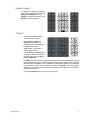
Lighting Control Console
Quick Guide
Version 3.1
C o p y r i g h t © E le c tr o n i c T h e a t r e C o n t r o l s , I n c .
All Rights reserved.
P r o d u c t in f o r m a t i on a n d s p e c i f i c a t i o n s s u bj e c t t o c h a n g e .
P a r t N u m b e r : 4110M1300-3.1 R e v A
Released: November 2002
ET C ®, E m p h a s i s ™ , E x p r e s s i o n ®, I n s i g h t ™ , I m a g i n e ™ , F o c u s ™ , E x p r e s s ™ , U n i s o n ®,
O b s e s s i o n ® I I , E T C N e t 2 ™ , E D M X ™ , S e n s o r ®, a n d W Y S I L i n k ™ a r e e i t h e r r e g i s t e r e d t r a d e m a r k s
o r t r a d e m a r k s o f E l e c t r o n i c T h e a tr e C o n t r ol s , I n c . i n t h e U n i t e d S t a t e s a n d o th e r c o u n t r i e s .
Table of Contents
Console Panels . . . . . . . . . . . . . . . . . . . . . . . . . . . 1
Keypad Features . . . . . . . . . . . . . . . . . . . . . . . . . . 3
Introduction to Programming . . . . . . . . . . . . . . . . . 6
Patching . . . . . . . . . . . . . . . . . . . . . . . . . . . . . . . . . 7
Working with Channels. . . . . . . . . . . . . . . . . . . . . . 8
Two-scene Operation . . . . . . . . . . . . . . . . . . . . . . . 9
Recording . . . . . . . . . . . . . . . . . . . . . . . . . . . . . . . 12
Playback. . . . . . . . . . . . . . . . . . . . . . . . . . . . . . . . 16
Disk Operations . . . . . . . . . . . . . . . . . . . . . . . . . . 17
Working with Moving Light (ML) Fixtures . . . . . . . 18
Express v3.1 Quick Guide
i
ii
Table of Contents
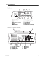
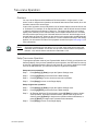
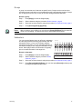
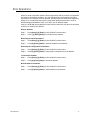
Console Panels
Back panel
Lamps 12V
Electronic Theatre Controls, Inc.
Product:
1.
2.
3.
4.
5.
6.
7.
8.
9.
10.
11.
12.
13.
Desk Light Dimmer
RFU fuse (T2.5A)
RFU
DMX512 Out (2 universes)
ETCLink
Disk Drive (side)
Power switch
Power input connector
Command Display output
Parallel Printer
Remote Macros
MIDI In/Out/Thru
ETCNet (newer facepanels do
not have Thin-net connector)
PUSH
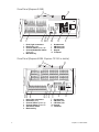
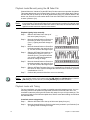
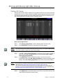
Face Panel (Express 125/250)
10
9
8
4
3
2
1
0
1.
2.
3.
4.
5.
Console Panels
Desk Light connectors
Disk Drive (side)
Submaster faders
Blackout key
Grandmaster
6.
7.
8.
9.
AB Fader pair
CD Fader pair
Keypad
Trackpad
1
Face Panel (Express 24/48)
1.
2.
3.
4.
Desk Light connectors
Disk Drive (side)
Channel faders (Scene A)
Channel/Submaster faders
(Scene B)
5. Blackout key
6.
7.
8.
9.
10.
Grandmaster
AB Fader pair
CD Fader pair
Keypad
Trackpad
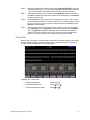
Face Panel (Express 48/96, Express 72/144 is similar)
Cha
1.
2.
3.
4.
5.
6.
2
Desk Light connectors
Disk Drive (side)
Channel faders (Scene A)
Channel faders (Scene B)
Submaster faders
Blackout key
7.
8.
9.
10.
11.
Grandmaster
AB Fader pair
CD Fader pair
Keypad
Trackpad
Express v3.1 Quick Guide
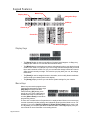
Keypad Features
Macro Keys
Display Keys
Navigation Keys
Stage
Blind
Patch
Setup
About
Learn
Help
Enter
Macro
M1
M2
M3
S1
S2
Page
Cue
7
8
Type
Sub
4
Link
Group
1
Wait
Time
S3
Cluster A
Cluster B
Track
M*
S4
S5
S6
S7
S8
9
Chan
Dim
5
6
Thru
At
2
3
And
Full
0
Record
Softkeys
Cluster C
Level
Enter
Clear
Focus
Point
Rel
Numeric Keypad
Display Keys
Stage
About
Blind
Learn
Patch
Setup
Enter
Macro
M1
M2
M3
S1
S2
S3
M*
S4
S5
S6
S7
S8
•
The [Stage] display is where most editing of channel levels happens. In Stage, any
changes you make are ‘live‘ and will take immediate effect.
•
The [Blind] display is used when you want to edit channel levels or cues but don’t need
or want a ‘live‘ result. For example, if you are running a show and decide that you would
like to add a channel at 50% to a cue, you can make the change in Blind and it won’t
affect the look currently on stage. The next time you play back your cue, the change
takes effect.
•
The [Patch] is used to assign dimmers to channels, and to modify dimmer attributes.
View and edit your channel patch in this display.
•
The [Setup] display is where you can edit the system settings for your console.
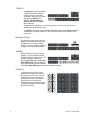
Mac ro Keys
Macro keys are used to program macro
functions and start macros. Macro keys
[M1]–[M3] access the first three
macros directly; [M*] allows you to
specify any one of the 2,000 macros
available and must be followed by a
number. [Macro Enter] is used when
programming macros.
Stage
Blind
About
Learn
Patch
Setup
Enter
Macro
M1
M2
M3
S1
S2
S3
M*
S4
S5
S6
S7
S8
A macro is a recorded series of keystrokes to be replayed later. Macros can execute any
console command (including softkeys and submaster bumps) and be linked to cues. For
example, if you record [Setup] [3] [Enter] [1] [Enter] [Enter] [Stage] into a macro, with
one keystroke you can save your show to disk and return to the Stage display. See your
user manual for more information on recording macros.
Keypad Features
3
Cluster A
•
The [About] key opens a window
containing information about a
channel, dimmer, or the show
according to which key you press
after pressing [About]. For
example, [About] [Chan] [3]
[Enter] will display information
about channel 3.
Stage
Blind
About
Learn
Patch
Setup
Enter
Macro
M1
M2
M3
S1
S2
S3
M*
S4
S5
S6
S7
S8
•
The [Learn] key enables you to record keystrokes in real time into macros as an
alternative to using editing screens.
•
The [Help] key provides context-sensitive assistance online. Press [Help] followed by
a second key (including softkeys) to open a window explaining the function of the
second key.
Navigation Keys
Use navigation keys to get around in
displays, move through menus, move
through fields in the Fixture Patch
display, or move to different attributes
or pages in the Fixture Box window.
Stage
Setup
About
Enter
Macro
M1
S1
M*
S2
S3
S4
S5
S6
S7
S8
S5
S6
S7
S8
Softkeys
Softkeys are found in many console
displays. They are identified for that
display at the bottom of the screen. You
M1
M2
activate a display’s softkeys by
pressing [S1]–[S8]. When softkey [S7 S1
S2
More Softkeys] is available, there are
more pages of softkeys for that display.
Press [S7 - More Softkeys] to access those additional pages.
Stage
Blind
About
Learn
Patch
Setup
Enter
Macro
M3
S3
M*
S4
Cluster B
In general, the keys in this cluster
pinpoint the elements that make up
the structure of your show. You will
use these keys when recording or
editing groups, cues or submasters.
Some allow you to change the
properties of recorded elements, such
as playback timing and relationships
with other elements.
4
Page
Cue
7
8
9
Chan
Dim
Type
Sub
4
5
6
Thru
At
Link
Group
1
2
3
And
Full
Wait
Time
Except
Level
Track
Record
Rel
Focus
Point
0
Clear
Enter
Express v3.1 Quick Guide
Numeric Keypad
The Numeric keypad is for numerical
entry. This grouping also includes the
[Enter] and [Clear] keys. Press
[Enter] to complete operations. Press
[Clear] to cancel operations.
Page
Cue
7
8
9
Chan
Dim
Type
Sub
4
5
6
Thru
At
Link
Group
1
2
3
And
Full
Wait
Time
Except
Level
Track
Record
Clear
Enter
Rel
Focus
Point
Page
Cue
7
8
9
Chan
Dim
Type
Sub
4
5
6
Thru
At
Link
Group
1
2
3
And
Full
Wait
Time
Except
Level
Track
Record
Rel
Focus
Point
0
Cluster C
•
•
•
•
Keypad Features
Use these keys when editing
channel levels and lists.
Use the [Thru], [And] and
[Except] keys to work with
multiple selections and ranges.
Use [At] when making
assignments, such as when
setting channel levels.
Use the [Full] and [Level] keys to
assign pre-defined levels (there is
no need to precede with [At] or
follow with [Enter]).
0
Clear
Enter
•
Use [Rel] to release selected, captured and independent channels. Selected channels
may be edited in any display. Channels may be captured in the Stage or Fader displays
and cannot be controlled by cues or submasters. Independent channels are unaffected
by Grandmaster, Flash, Solo and Blackout controls. Press [Rel] 1–3 times to release
channels in the following order: first selected channels, then captured channels, then
independent channels.
•
Use the [Focus Point] key to set levels by reference.
5
Introduction to Programming
The procedures explained in this introductory guide are grouped under the following
categories:
•
Patching ~ What it means and how to do it.
•
Working with Channels ~ Select and set channel levels.
•
Two-scene Operation ~ Using the manual playback features.
•
Recording ~ Steps to follow to record cues, groups, submasters, focus points and
effects (chases).
•
Playback ~ See the results of your recordings.
•
Disk Operations ~ Save and retrieve showfiles.
•
Working with Moving Light (ML) Fixtures ~ Patch, select and set attribute levels.
Text Conventions
Many procedures are identified and explained by example on the following pages. To keep
things simple and concise, we’ve adopted the following notations in this document.
•
[At], [Cue]
Keys (sometimes called buttons) found on the
keyboard are shown with square brackets.
•
[S1 - Select Cue]
Softkeys in displays are shown with the softkey
number and label bracketed in bold type. If a
designated softkey is not visible in your display, you
may need to press [S7 - More Softkeys] to scroll
through the available pages.
•
{Cue}
Keys that are optional in a procedure are shown in
curly brackets.
•
[#]
The numerical label of one or more elements, such as
the number of a cue or the numbers of all channels in
a selection list.
•
[x]
Values other than numerical labels, such as levels or
times, are shown as an italicized “x” in square
brackets. What “x” stands for will be defined in that
step.
•
Channel Selection, page 8 References to instructions provided elsewhere in the
Quick Guide are indicated in italics. When viewing this
document electronically, click the reference to jump to
that section.
Display Assistance
You will find context-sensitive assistance in two places on Command monitor screens. In
the upper right corner the console tells you what entry is expected next. In red text just
above the softkeys, the console gives you instructions and identifies your options.
Setup Display
Your console comes with default settings that can be changed in the Setup display. These
settings have an overall affect on your shows and on the programming environment. Enter
the Setup display by pressing [Setup] on the console keypad. Navigate to a Setup menu,
and through subsequent menus, by pressing the menu’s number followed by [Enter].
6
Express v3.1 Quick Guide
Patching
Conventional lights are powered by dimmers, which in turn are controlled by console
control channels. You associate certain dimmers with certain channels by performing a
patch in the Patch display, and then record the channels into show elements such as cues,
groups or submasters. You may patch more than one dimmer to a channel, but dimmers
may only be assigned to one channel at a time. Your console is shipped with a default patch
that associates each dimmer with control channels on a 1:1 basis.
When there are moving lights in your show, you need to use the Setup menu Moving Light
Functions menu to patch the multiple attributes of those fixtures (see Working with Moving
Light (ML) Fixtures, page 18).
Patch dimmers to channels:
Note:
Patching
Step 1:
Press [Patch] to go to the channel patch display.
Step 2:
Press {Dim} [#] [Enter] {Channel} [#] [Enter]. Repeat for all the dimmers you
want to patch.
If the LED on the [Channel] key is lit before you start, you must press [Dim] before
entering the first number. To unpatch, use the same procedure but press “0” for the
channel number, or press [Dim] [#] [S6 - Unpatch].
7
Working wi th Channels
Channel Selection
To set a level for a channel, you must select it. Selecting a channel is as easy as pressing
its number on the keypad. You may also use the [And], [Thru] and [Except] keys to select
ranges of channels. The Stage display will default to channel selection. The Blind display
defaults to cue selection, so you will need to press the [Channel] key prior to entering
channel numbers.
Select channels:
•
Press [Channel] [#].
•
To select a range of channels press [Channel] [#] [Thru] [#] [And] [#].
Note:
In the Stage display, the [Channel] key is optional when the channel LED is lit.
To remove channels from a range, use the [Except] key. [Channel] [1] [Thru] [10]
[Except] [5] [And] [Except] [7] selects channels 1-4, 6, and 8-10.
Set Channel Levels
After making a channel selection, set channel levels using any of the procedures below.
You may also set channel levels by referencing focus points, but that procedure usually is
employed for setting attribute levels for moving light fixtures. Information about focus points
is given in Focus Points, page 21.
Using the trackpad:.
•
Slide your finger vertically on the trackpad. Press the coarse and
fine “buttons” to the left of the trackpad to adjust the sensitivity of
the trackpad.
Using the numeric keypad:
•
Press [At] [x] {Enter}. [x] can be a single- or double-digit entry. For 50%, you can type
[At] [5][0], or you can type [At] [5] Enter]. For a level of 5%, you must enter [At] [0][5].
Using pre-defined levels:
•
Press [Full] or [Level]. You can change the value of the [Level] key in the Systems
Settings menu.
•
Press [At] [Clear] to quickly set channels to 0%.
Using the [+] and [–] keys:
•
8
Press [At] followed by pressing the [+] or [–] keys as often as you wish to increment or
decrement the level by one percent.
Express v3.1 Quick Guide
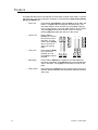
Two-scene Operation
Overview
You can use the Express 24/48, 48/96 and 72/144 consoles in “single-scene” or “twoscene” mode. In single-scene operation, the channel faders access the first 48, 96 or 144
channels, based on the console type.
In two-scene operation, the top and bottom rows of channel faders access the first 24, 48
or 72 channels. For example, on an Express 24/28, fader 1 and 25 will both access channel
1, faders 2 and 26 access channel 2, and so on. Two-scene mode allows you to setup
lighting looks manually on the channel faders and crossfade between them. In all cases,
two-scene mode uses the top row of channel faders as “Scene A” and the bottom row of
channel faders as “Scene B”. When you are running in two-scene mode, the AB Fader pair
is used to crossfade from Scene A to Scene B. You can crossfade manually or with timing
applied. You can use the CD Fader Pair to playback recorded cues (see Cues, page 12, for
more information).
Note:
The Express 24/48 also has the ability to run in single-scene mode with channel and
submaster faders available. In that case, the top row of channel faders correspond to
channels 1-24, and the bottom row becomes submasters 1-24.
Setup Two-scene Operation
To change the operation mode of your Express 24/48, 48/96 or 72/144, you will need to use
the Setup display. Once you have enabled two-scene operation, the AB Fader Pair can only
be used for crossfading between Scene A and Scene B. If you want to playback recorded
cues on the AB Fader Pair, you will need to return to single-scene operation.
Setup two-scene operation:
Step 1:
Press [Setup] [1] [Enter] to open the System Settings menu.
Step 2:
Press [1][5] [Enter] to select the Scene Mode settings.
Step 3:
Press [1] [Enter] to set the console to two-scene operation.
Step 4:
Press [Stage] to return to the Stage display.
Setup single-scene operation:
Step 1:
Press [Setup] [1] [Enter] to open the System Settings menu.
Step 2:
Press [1][5] [Enter] to select the Scene Mode settings.
Step 3:
On Express 48/96 and 72/144 consoles, press [0] [Enter] to return to singlescene operation. On Express 24/48 consoles, you have two single-scene
choices: press [2] [Enter] for single-scene operation without submasters, or
press [3] [Enter] for single-scene operation with submasters.
Step 4:
Press [Stage] to return to the Stage display.
Two-scene Operation
9
Playback Looks Manually using the AB Fader Pair
Channel faders are “mastered” by the AB Fader Pair when two-scene operation is enabled.
This means that the top row of channel faders, Scene A, will be active when the A Fader in
the AB Fader Pair is at the top of its travel (farthest away from you). Channel faders in the
bottom row, Scene B, are active when the B Fader in the AB Fader Pair is at the bottom of
its travel (closest to you).
Note:
If you place the A Fader and B Fader off their respective zero position (for example, both
at full), both Scene A and Scene B become active. In that case, the channel fader at the
highest level will control the output for that channel.
Playback lighting looks manually:
Step 1:
Step 2:
Note:
Slide the AB Fader Pair to the top of
their travel (away from you).
Move the channel faders on Scene A to
the levels you want in your first look
(Cue 1). Lighting levels will change on
stage.
Step 3:
Move the channel faders on Scene B to
the levels needed in the next look (Cue
2). This will not affect the stage output.
Step 4:
Slide the AB Fader Pair toward you to
crossfade from Scene A (Cue 1) to
Scene B (Cue 2). The speed at which
you move the AB Faders determines
the rate of change on stage.
Channels
10
9
8
7
10
9
8
7
6
5
4
6
5
4
2
1
0
1
2
1
0
2
3
4
5
6
7
8
6
5
4
6
5
4
2
1
0
2
1
0
9
10
11
10
9
8
7
10
9
8
7
6
5
4
6
5
4
2
1
0
49
50
1
51
2
2
1
0
52
3
53
4
2
1
0
54
5
55
6
12
2
1
0
56
7
57
8
58
9
59
60
12
Step 5:
Move the channel faders on Scene A to
the levels needed in the next look (Cue
3). This will not affect the stage output.
Step 6:
Slide the AB Fader Pair away from you to crossfade from Scene B (Cue 2) back
into Scene A. Since you have changed the channel levels on Scene A, you have
crossfaded into “Cue 3”.
Step 7:
Continue this process to fade from cue to cue manually.
You can flash scenes to full output using the [AB-Clear] and [AB-Back] keys. Use the
[AB-Clear] key to flash Scene A, and the [AB-Back] key to flash Scene B.
Playback Looks with Timing
For long crossfades, you may not want to crossfade manually between scenes. You can
set timing values for the upfade and downfade movement on the AB Fader Pair. The
crossfade is started by moving the AB Faders fully away from you or fully toward you. The
scene that is fading in will follow the upfade time, and the scene that is fading out will follow
the downfade time.
Crossfade scenes using timing:
10
Step 1:
Slide the AB Fader Pair to the top of their travel (away from you).
Step 2:
Move the channel faders on Scene A to the levels you want in your first look (Cue
1). Lighting levels will change on stage.
Express v3.1 Quick Guide
Step 3:
Move the channel faders on Scene B to the levels needed in the next look (Cue
2). This will not affect the stage output.
Step 4:
Press [AB-Rate] [x] [Enter], where
[x] is the upfade time.
Step 5:
Step 6:
Note:
Two-scene Operation
A
C
D
Clear
Press [x] [Enter], where [x] is the
downfade time. If the downfade time
is the same as the upfade time, just
press [Enter]. The Rate key will blink
to indicate that it is active.
Move the AB Faders toward you.
When they reach the end of travel, the
timed fade will begin. Timing will
remain active on the AB Fader Pair
until you press [AB-Rate] again.
B
Clear
10
10
9
8
7
6
5
4
3
2
1
0
Rate
7
6
5
4
3
2
1
0
Go
Back
Hold
Go
Rate
Back
Hold
You can pause a timed crossfade using the [AB-Hold] key. To resume the fade, press
[AB-Go].
11
Recording
You can record channel levels into submasters, groups and cues in both the Stage and
Blind displays. Remember that working in Stage affects the output of the console. Changes
made in Blind affect only the stored data. If you modify a cue in Blind, you must play it back
in Stage to see the changes in real life.
Cues
A lighting cue is typically a “look” on stage that can be played by pressing a fader Go key.
You create a cue by selecting patched channels, setting their levels and recording all this
information to a cue number. After that, adjust playback timing if you wish.
Record a cue in Stage:
Note:
Step 1:
Press [Stage] to enter the Stage display.
Step 2:
Select channels using the procedure Select channels:, page 8.
Step 3:
Set levels for those channels using the procedure Set Channel Levels, page 8.
Step 4:
Press [Record] [Cue] [#] [Enter].
For information on Effect cues, see Effects (Chases), page 14.
Cue Fade and Wait Times
Recorded cues will default to the upfade and downfade times set in the System Settings
menu (the console defaults to five second up- and downfades). Cue fades start as soon as
you press [Go], but you can delay fades by setting upfade and downfade wait times.
Set a new default fade time:
Step 1:
Press [Setup] [1] [Enter] to view the System Settings menu.
Step 2:
Press [3] [Enter] [x] [Enter] {x} [Enter], where [x] is the new default upfade
time, and {x} is the new downfade time if it is different from the upfade time.
Edit cue fade times:
Step 1:
Select the [Stage] or [Blind] display.
Step 2:
Press [Cue] [#] [Time] [x] [Enter] {x} [Enter], where [x] is the new cue upfade
time, and {x} is the new downfade time if it is different from the upfade time. If you
want to change only the downfade time, press [Time] twice before entering a
value.
Edit cue fade wait times:
12
Step 1:
Select the [Stage] or [Blind] display.
Step 1:
Press [Cue] [#] [Wait] [x] [Enter] {x} [Enter], where [x] is the new cue upfade
wait time, and {x} is the new downfade wait time if it is different from the upfade
time. If you want to change only the downfade wait time, press [Wait] twice
before entering a value.
Express v3.1 Quick Guide
Groups
A group is a recorded set of channels at specific levels. Groups can be used to select
channels and set levels that you use repeatedly through a programming session. Groups
are not played back like cues, so they do not have timing associated with them.
Record a group:
Note:
Step 1:
Press [Stage] to enter the Stage display.
Step 2:
Select channels using the procedure Select channels:, page 8.
Step 3:
Set levels for those channels using the procedure Set Channel Levels, page 8.
Step 4:
Press [Record] [Group] [#] [Enter].
When creating a group in Blind, you should press [Group] [#] [Enter] first to select the
group you are creating. This will ensure that you start with an empty group.
Submasters
You can record a lighting look or an effect to a submaster
and then play back the recording proportionally with the
submaster’s fader, or force it to full output using the
submaster bump button. You can also apply timing to a
submaster and play it back using the submaster’s bump
button. When played back, the submaster will typically
pile-on recorded channels to the stage look.
Record a submaster:
Recording
Submasters
1
10
9
10
9
10
9
10
9
2
1
0
2
1
0
2
1
0
4
3
2
1
0
2
3
4
5
6
7
8
Step 1:
Press [Stage] to enter the Stage display.
Step 2:
Select channels using the procedure Select
channels:, page 8.
Step 3:
Set levels for those channels using the procedure Set Channel Levels, page 8.
Step 4:
Press [Record] [Sub] [#] [Enter]. You can also press [Record] and then press
the target submaster’s bump button.
13
Effects (Chases)
An effect is a special cue or submaster that can run repetitively in a variety of patterns.
Effects are also called chases. Effects consist of a series of steps that contain channels set
at levels. You can assign timing conditions to each step and separately to the overall effect.
You can record an effect in the Stage or Blind display, but you can only edit effects in Blind.
Record an effect in Blind (example):
Step 1:
Press [Blind] to enter the Blind display.
Step 2:
Press {Cue} [#] [Type] [3] [Enter] to specify the cue number and set it to the
effect type. This also selects Step 1 for editing.
Step 3:
Press [Channel] [1] [Thru] [5] [S8 - Add Channels] [At] [5][0] to set channels
1-5 to a maximum level of 50%. You can also select channels individually to set
levels after you add them.
Step 4:
Press [S1 - Step] [2] to create the next step and select it for editing.
Step 5:
Press [Channel] [6] [Thru] [1][0] [S8 - Add Channels] [At] [7][5] to add
channels 6-10 to step 2 and set them to a maximum level of 75%.
Step 6:
Press [Record] [Enter] to record the effect cue.
E f f e c t F a d e T i m es
When an effect is created, it defaults to zero timing for overall fade and step fades. Each
step defaults to a .2 second step time, which means that step 2 plays .2 seconds after step
1, and so on. You can change the timing on the overall effect, which will determine how long
it takes for the whole effect to fade to maximum levels, stay active and fade out again. You
may also add in, dwell and out times to each step to change from a chase that snaps
between the minimum and maximum levels to one that fades. If the In/Dwell/Out time
combined is greater than the step time, your steps will crossfade from one to the next.
Change an effect cue’s overall timing:
14
Step 1:
Press [Blind] to enter the Blind display.
Step 2:
Press {Cue} [#] [Time] [x] [Time] [x] [Time] [x] [Enter], where the first time
number entered is for the upfade time, the second is for the dwell time and the
third is for the downfade time. Any of the three can be skipped by pressing [Time]
without following it with a number. The dwell time is the amount of time the effect
Express v3.1 Quick Guide
stays active before fading itself down. A dwell time of “Hold” will keep the effect
running until the next cue is played.
Step 3:
Press [Record] [Enter] to save your changes.
Change an effect step’s timing:
Step 1:
Press [Blind] to enter the Blind display.
Step 2:
Press {Cue} [#] [Enter] to select the effect cue you want to edit.
Step 3:
Press [S1 - Step] [#] [Enter] [S7 - More Softkeys] [S3 - In/Dwell/Out][x]
[Enter] [x] [Enter] [x] [Enter], where the first time number entered is for the in
time, the second is for the dwell time and the third is for the out time. Any of the
three can be skipped by pressing [S3 - In/Dwell/Out] without following it with a
number. The dwell time is the amount of time the step stays active before fading
itself down.
Step 4:
Press [Record] [Enter] to save your changes.
Effect Attributes
You can change the way an effect plays by changing its attributes. Effects are either
Positive or Negative but can have other attributes as well (for example, Reverse, Bounce
and Random).
Change an effect cue’s attributes:
•
Recording
Press [Blind] {Cue} [#] [S7 - More Softkeys] [S8 - Attribute], and select from the
softkeys. To remove an attribute, press the corresponding softkey again.
15
Playback
Cue playback takes place in the AB and CD Fader pairs in single-scene mode, or just the
CD Fader pair in two-scene operation. Playback is controlled by the [Go], [Clear], [Hold],
[Back] and [Rate] keys.
•
Play a cue
Press {Stage} [Cue] [#] [Go], using the [Go] key of the AB or CD
faders. To playback the cue using the recorded timing, move
both fader sliders to level 10 before you press [Go]. If playing
back in manual timing, move both fader sliders to level 0 before
you press [Go], then move the sliders in your own timing.
pressing [Go] again plays the next cue in the cue list.
•
Clear a cue
Press a fader’s
[Clear] key to remove
the current cue from
that fader. You may
need to press [Clear]
twice to remove an
effect cue from the
fader.
•
16
Hold a cue
Press a fader’s [Hold]
key to pause the
playback of a cue.
Press [Go] to resume
the fade.
A
B
C
D
Clear
Clear
10
10
9
8
7
6
5
4
3
2
1
0
Rate
7
6
5
4
3
2
1
0
Go
Back
Hold
Go
Rate
Back
Hold
•
Move back
Press a fader’s [Back] key to replay the cue that played just
previously in that fader. Press [Back] again to move backward in
order in that fader. Press [Go] to move forward in order in that
fader.
•
Rate control
Press a fader pair’s [Rate] key to take manual control of the cue’s
fade rate with the trackpad. This command is especially useful for
effect cues.
Express v3.1 Quick Guide
Disk Operations
When you write to a diskette, both the show programming and the console’s configuration
are stored to the diskette. However, you may read show and configuration information
separately from a showfile stored on diskette. Reading these two components separately
allows you to conveniently keep system configuration preferences the same, such as
default settings and hardware setup, even when you run different shows.
Insert a 1.44 MB high density diskette into the console’s disk drive, then proceed as follows
to write to or read from the diskette.
Write to diskette:
Step 1:
Press [Setup] [3] [Enter] to view the Disk Functions menu.
Step 2:
Press, [1] [Enter] [Enter] to write the show to diskette.
Read only the show information:
Step 1:
Press [Setup] [3] [Enter] to view the Disk Functions menu.
Step 2:
Press [2] [Enter] [Enter] to read show data from the diskette.
Read only the configuration information:
Step 1:
Press [Setup] [3] [Enter] to view the Disk Functions menu.
Step 2:
Press [3] [Enter] [Enter] to read system configuration from the diskette.
To format the diskette:
Step 1:
Press [Setup] [3] [Enter] to view the Disk Functions menu.
Step 2:
Press [4] [Enter] [Enter] to format the diskette.
Read all data from diskette:
Disk Operations
Step 1:
Press [Setup] [3] [Enter] to view the Disk Functions menu.
Step 1:
Press [5] [Enter] [Enter] to read all data from the diskette.
17
Working wi th Moving Light (ML) Fixtures
Patching ML Fixtures
Use the Fixture Patch display to patch one or more ML fixtures at a time. When you patch
multiple fixtures at once, Start Channels and DMX512 Start addresses will auto-increment
to the next available address. Note that resulting Intensity Channels are identified in the
table. Moving lights are selected by fixture number for control.
Patch moving light fixtures:
Note:
Note:
Step 1:
Press [Setup] [1][5] [Enter] to view the Moving Light Functions menu.
Step 2:
Press [2] [Enter] to view the moving light Fixture Patch display.
You can also access the Fixture Patch from the Patch display. Press [S8 - Fixture Patch]
in the Patch display to switch over to the Fixture Patch.
Step 3:
Press [S1 - Select Fixture] [#] [Enter] to select the fixture number you want to
patch. You can patch multiple fixtures at one time by pressing [S1 - Select
Fixture] [#] [Thru] [#] [Enter].
Step 4:
Press [#] [Enter] to set the personality number. If you do not know the
personality number, press [S8 - Return] [1] [Enter] to view the Personality Setup
display. Press [S8 - Return] [2] [Enter] to return to the Fixture Patch display.
If your fixture is not listed, there may be a personality already built and available for
download at http://www.etcconnect.com/service/service_xprn_pers.asp
You can build a profile using the Expression Personality Editor that came with your
console. If you do not have the Expression Personality Editor, you can download it at
http://www.etcconnect.com/service/service_offline_software.asp?10
Step 5:
18
Press [#] [Enter] to set the start channel of the first (or only) selected fixture. This
value cannot be patched to another fixture.
Express v3.1 Quick Guide
Step 6:
Specify the DMX512 Start address by pressing [#] [Enter] [#] [Enter], where the
first number entered is 1, 2 or 3 to set the output port, and the second number is
1-512 for the DMX512 Start address for the first (or only) selected fixture.
Step 7:
If the fixture requires a remote dimmer, press [#] [Enter], where the number is
the DMX512 address for that dimmer. If there is no remote dimmer, press [Enter]
to skip over this column.
Step 8:
Press [1] [Enter] to swap the pan and tilt attributes on a fixture. This is useful
when the hanging position of a fixture makes the pan movement look more like
tilt, and vice versa. If you do not want to swap the pan and tilt attributes, press
[Enter] to skip this setting.
Step 9:
The Flip setting inverts the movement of pan and/or tilt movement for a fixture.
Press [Enter] to skip, or [1] [Enter] to flip the pan movement. Press [Enter] to
skip, or [1] [Enter] to flip the tilt movement. Flip is useful when the hanging
position of a fixture causes the pan or tilt of a fixture to move opposite other
fixtures, such as when moving-mirror fixtures are hung head-to-head.
Fixture Box
When a fixture is selected, a special window called the Fixture Box appears at the bottom
of the Command display. All channels belonging to a particular fixture and assigned to
encoder control are displayed in five encoder pages.
Operating in the Fixture Box:
•
Scroll through fixtures
Press [+] or [–]
•
Scroll through attributes
Press [s] or [t]
•
Scroll through attribute pages
Press [u] or [v]
Working with Moving Light (ML) Fixtures
19
Select ML Fixtures
To control a moving light, you must select it. Selecting a moving light is done by the fixture
number you set in the patch. You may also use the [And], [Thru] and [Except] keys to
select ranges of fixtures.
Select fixtures:
•
Press [S8 - Fixture] [#].
•
To select a range of fixtures press [S8 - Fixture] [#] [Thru] [#] [And] [#]. When a range
of fixtures is selected, only the last fixture in the range is displayed in the Fixture Box.
Select a Fixture Attribute
Your console supports up to 64 fixture attributes. These attributes are numbered 1-64.
Though you can directly change attribute levels directly using the encoders, you may select
a particular attribute by selecting its number.
When selecting an attribute by its number, the attribute is highlighted in the Fixture Box. The
steps to follow to select a fixture attribute are illustrated below.
View the attribute numbers:
Step 1:
Press [Setup] [1][5] [Enter] to view the Moving Light Functions menu.
Step 2:
Press [3] [Enter] to view the Attribute Setup display. All attributes have a number
associated with them.
Select a fixture attribute:
Step 1:
Press [S8 - Fixture] [#] [Only] [S6 - Attribute] [x], where [x] is the attribute
number you want to select.
Step 2:
Use the associated encoder to set a level, or press [At] [x], where [x] is the level
you want to set for that attribute.
Select Attributes by Category
Each attribute is assigned by default to one of five categories: Position, Beam, Image, Color
or None. Often, you may want to adjust or record all the attributes in a category.
Select all the attributes in an attribute category:
Step 1:
Press [S8 - Fixture] [#] [Only] [S1 - Position] to select the position attributes.
You can substitute [S2 - Image], [S3 - Color], [S4 - Beam] or [S5 - None] for
[S1 - Position] to select other attribute categories.
Step 2:
Use the associated encoder to set a level, or press [At] [x], where [x] is the level
you want to set for that attribute.
Set Attribute Levels
After making ML fixture and attribute selections, set attribute levels using any of the
procedures below. Since attributes are associated with channels in Fixture Patch, you can
set attributes levels using the procedures given under Set Channel Levels, page 8. But
easier ways are available for ML fixtures that employ the Fixture Box and reference groups
called Focus Points.
Find out which device controls which attribute by selecting a fixture, then looking in the
Fixture Box. The attributes of the fixture and their associated level-setting devices are
highlighted. The devices are shown in the third row of the table, where E1–E5 are encoders,
X and Y are the two wheels, and TX and TY are the two axes of the pointing device. These
20
Express v3.1 Quick Guide
encoder assignments refer to the Expression 3 and Insight 3 hardware. On an Express
console, use the navigation keys to move among attributes and pages. When pan or tilt is
selected, the trackpad can be used to control movement.
Setting the intensity directly:
Step 1:
Select fixtures using the procedure described in Select ML Fixtures, page 20.
Step 2:
Press [At] [x], where [x] is the intensity level. You can also use the [Full] and
[Level] keys.
Using Focus Points (see below):
Step 1:
Select fixtures using the procedure described in Select ML Fixtures, page 20.
Step 2:
Select an attribute or attribute category using the procedures Select a Fixture
Attribute, page 20 or Select Attributes by Category, page 20.
Step 3:
Press [At] [Focus Point] [#] [Enter].
Using encoder settings:
Step 1:
Select fixtures using the procedure described in Select ML Fixtures, page 20.
Step 1:
Select an attribute or attribute category using the procedures Select a Fixture
Attribute, page 20 or Select Attributes by Category, page 20.
Step 2:
Use the arrow keys and trackpad to set attribute levels.
Foc us Points
Focus points are special groups that are used by reference. They are most often used to
set the levels of ML fixtures. Levels that reference a focus point automatically update if the
corresponding levels in the focus point change.
Record a Focus Point:
Step 1:
Press [Stage] to enter the Stage display.
Step 2:
Select channels using the procedure Select channels:, page 8.
Step 3:
Set levels for those channels using the procedure Set Channel Levels, page 8.
Step 4:
Press [Record] [Focus Point] [#] [Enter].
Working with Moving Light (ML) Fixtures
21
22
Express v3.1 Quick Guide
Americas 3030 Laura Lane, P.O. Box 620979, Middleton, Wisconsin 53562-0979 USA Tel: +608 831 4116 +800 688 4116 Fax: +608 836 1736 +800 555 8912
Europe Unit 4, Victoria Industrial Estate, Victoria Road, London W3 6UU, UK Tel: +44 (0)20 8896 1000 Fax: +44 (0)20 8896 2000
Asia Room 605-606, Tower III Enterprise Square, 9 Sheung Yuet Road, Kowloon Bay, Kowloon, Hong Kong Tel: +852 2799 1220 Fax: +852 2799 9325
Web: www.etcconnect.com Email: (US) [email protected] (UK) [email protected] (Asia) [email protected]
Service: [email protected] Toll free: 800 775 4382 Comments about this document: [email protected]
Copyright © 2002 Electronic Theatre Controls, Inc. All Rights Reserved. Product information and specifications subject to change.
4110M1300-3.1 Rev A Released 11/02