1
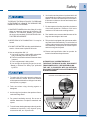
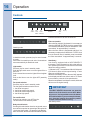
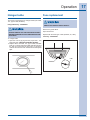
Use & Care Guide
Installation Instructions
Vent Hood
04307838/2N - 08/2007
2
Finding Information
Please read and save this guide
Thank you for choosing Electrolux, the new premium brand in home appliances. This Use & Care Guide
is part of our commitment to customer satisfaction and product quality throughout the service life of your
new appliance.
We view your purchase as the beginning of a relationship. To ensure our ability to continue serving you,
please use this page to record important product information.
Keep a record for quick reference
Purchase date
Electrolux model number
Electrolux serial number (see picture for location)
NOTE
Registering your product with Electrolux enhances
our ability to serve you. You can register online at
www.electroluxusa.com or by dropping your
Product Registration Card in the mail.
Questions?
For toll-free telephone support in the U.S. and Canada:
1-877-4ELECTROLUX (1-877-435-3287)
For online support and Internet product information visit http://www.electroluxusa.com
Table of contents
Finding information ................................................ 3
SAFETY .............................................................. 4
Verify package contents............................................6
Installation ........................................................... 7
• Install the ductwork .............................................................. 7
• Wiring.................................................................................8
• Install mounting bracket ....................................................... 9
• Install flue mounting bracket ................................................ 9
• Prepare the hood ................................................................ 10
• Install the hood ................................................................... 12
• Install filters.......................................................................14
©2007 Electrolux Home Products, Inc.
Maintenance ....................................................... 15
• Grease filters ....................................................................... 15
• Non-Ducted recirculation filters .......................................... 15
• Hood cleaning .................................................................... 15
Operation ........................................................... 16
• Controls.............................................................................16
• Halogen bulbs....................................................................17
• Fuse replacement...............................................................17
Warranty information..............................................18
All rights reserved. Printed in Italy
3
4
Safety
Important Safety Instructions
Read all instructions before using this
appliance.
Save these instructions for future
reference.
Do not attempt to install or operate your
appliance until you have read the safety
precautions in this manual. Safety items
throughout this manual are labeled with a
WARNING or CAUTION based on the risk type.
This symbol alerts you to
situations that may cause
serious body harm,
death or property
damage.
This symbol alerts you to
situations that may cause
bodily injury or property
damage.
INTENDED FOR DOMESTIC COOKING
ONLY
TO REDUCE THE RISK OF FIRE, ELECTRIC
SHOCK, OR INJURY TO PERSONS, OBSERVE THE
FOLLOWING:
1. Use this unit only in the manner intended by the
manufacturer. If you have questions, contact the
manufacturer at the address or telephone number
listed in the warranty.
2. Before servicing or cleaning unit, switch power off
at service panel and lock service panel to prevent
power from being switched on accidentally. When
the service disconnecting means cannot be locked,
securely fasten a prominent warning device, such
as a tag, to the service panel.
3. Installation work and electrical wiring must be done
by a qualified person(s) in accordance with all applicable codes and standards, including fire-rated
construction codes and standards.
4. Sufficient air is needed for proper combustion and
exhausting of gases through the flue (chimney) of
fuel burning equipment to prevent backdrafting. Follow the heating equipment manufacturer’s guide-
lines and safety standards such as those published
by the National Fire Protection Association (NFPA),
and the American Society for Heating, Refrigeration and Air Conditioning Engineers (ASHRAE), and
the local code authorities.
5. When cutting or drilling into wall or ceiling, do not
damage electrical wiring and other hidden utilities.
6. Ducted fans must always be vented to the outdoors.
7. Do not use this unit with any separate solid-state
speed control device.
8. To reduce the risk of fire, use only metal ductwork.
9. This unit must be grounded.
TO REDUCE THE RISK OF A RANGE TOP GREASE
FIRE:
A. Never leave surface units unattended at high
settings. Boilovers cause smoking and greasy
spillovers that may ignite. Heat oils slowly on low
or medium settings.
B. Always turn hood ON when cooking at high heat or
when flambeing food (i.e. Crepes Suzette, Cherries
Jubilee, Peppercorn Beef Flambe’).
C. Clean ventilating fans frequently. Grease should not
be allowed to accumulate on fan or filter.
D. Use proper pan size. Always use cookware
appropriate for the size of the surface element.
Safety
TO REDUCE THE RISK OF INJURY TO PERSONS
IN THE EVENT OF A RANGE TOP GREASE FIRE,
OBSERVE THE FOLLOWING:*
1. SMOTHER FLAMES with a close-fitting lid, cookie
sheet, or metal tray, then turn off the burner. BE
CAREFUL TO PREVENT BURNS. If the flames
do not go out immediately, EVACUATE AND CALL
THE FIRE DEPARTMENT.
2. NEVER PICK UP A FLAMING PAN - You may be
burned.
3. DO NOT USE WATER, including wet dishcloths or
towels - violent steam explosion will result.
4. Use an extinguisher ONLY if:
A. You know you have a Class ABC extinguisher
and you already know how to operate it.
B. The fire is small and contained in the area where
it started.
C. The fire department is being called.
D. You can fight the fire with your back to an exit.
* Based on “Kitchen Fire Safety Tips” published
by NFPA.
6. Your hood motor has a thermal overload which will
automatically shut off the motor if it becomes overheated. The motor will restart when it cools down.
If the motor continues to shut off and restart, have
the hood serviced.
7. For best capture of cooking impurities, the bottom
of the hood should be a minimum of 24" and a
maximum of 30" above the cooking surface.
8. Two installers are recommended because of the
large size and weight of this hood.
9. This product is equipped with a thermostat which
may start blower automatically. To reduce the risk
of injury and to prevent power from being switched
on accidentally, switch power off at service panel
and lock or tag service panel.
10. Please read specification label on product for
further information and requirements.
AUTOMATICALLY OPERATED DEVICE.
TO REDUCE THE RISK OF INJURY, DISCONNECT
FROM POWER SUPPLY BEFORE SERVICING.
THE UNIT IS EQUIPPED WITH AN INTEGRAL
DISCONNECTING SWITCH LOCATED INSIDE THE
BLOWER HOUSING.
INTEGRAL DISCONNECTING SWITCH
1. To reduce risk of fire and to properly exhaust air,
be sure to duct air outside. Do not vent exhaust
air into spaces within walls or ceilings or into attics,
crawl spaces, or garages.
2. Take care when using cleaning agents or
detergents.
3. Avoid using food products that produce flames
under the Range Hood.
4. For general ventilating use only. Do not use to
exhaust hazardous or explosive materials and
vapors.
5. To avoid motor bearing damage and noisy and/or
unbalanced impellers, keep drywall spray,
construction dust, etc. off power unit.
5
6
Verify package contents
Unpack hood and check contents.
You should receive:
1 - Hood
1 - Decorative Flue Assembly
1 - Parts Bag containing:
1 - Mounting Bracket
1 - Discharge Collar
1 - Flue Mounting Bracket
6 - Mounting Screws (4,8 x 38mm Pan Head)
7 - Mounting Screws (3,9 x 9,5mm Pan Head)
2 - Mounting Screws (3.9 x 6mm Flat Head)
6 - Drywall Anchors
2 - Grease Filters
1 - Installation Instructions
1 - Warranty Card
DECORATIVE
FLUE
MOUNTING
BRACKET
GREASE
FILTERS
DISCHARGE
COLLAR
7 MOUNTING
SCREWS (3,9 x
9,5mm Pan Head)
2 MOUNTING SCREWS
(3.9 x 6mm Flat Head)
FLUE MOUNTING
BRACKET
6 MOUNTING SCREWS
(4,8 x 38mm Pan Head)
6 DRYWALL
ANCHORS
Installation
Install the ductwork
ROOF CAP
To reduce the risk of fire, use only metal
ductwork.
ROUND DUCT
1. Decide where the ductwork will run between the
hood and the outside.
DECORATIVE
FLUE
2. A straight, short duct run will allow the hood to
perform most efficiently.
WALL
CAP
HOOD
ROUND
ELBOW
3. Long duct runs, elbows, and transitions will reduce
the performance of the hood. Use as few of them
as possible. Larger ducting may be required for best
performance with longer duct runs.
4. Install a roof or wall cap. Connect round metal
ductwork to cap and work back towards hood
location. Use duct tape to seal the joints between
ductwork sections.
5. Never make the size or area of the ductwork smaller
than the size that originates at the hood.
6. Bigger ductwork is better.
7. Keep duct lenght less than 50 linear feet.
8. Minimize use of elbows and transitions (4 or less).
9. Always separate 90 degree elbows with at least 2
feet of straight ductwork.
10. Place transitions at least 1 foot from the hood
outlet.
24” TO 30” ABOVE
COOKING SURFACE
6”
ADAPTER
7
8
Installation
Wiring
This range hood must be properly grounded.
The unit should be installed by a qualified
electrician in accordance with all applicable
national and local electrical codes.
GROUNDING INSTRUCTIONS
This appliance must be grounded. In the event of an
electrical short circuit, grounding reduces the risk of
electric shock by providing an escape wire for the
electric current.
This appliance is equipped with a cord having a
grounding wire with a grounding plug.
The plug must be plugged into an outlet that is properly
installed and grounded.
Improper grounding can result in a risk of
electric shock.
Consult a qualified electrician if the grounding
instructions are not completely understood, or if doubt
exists as to whether the appliance is properly
grounded.
Do not use an extension cord.
If the power supply cord is too short, have a qualified
electrician install an outlet near the appliance.
Set the electrical power supply within the space covered
by the decorative flues.
Position the power socket at a maximum distance of
33-7/16” (85 cm) from where the lead exits from the
hood (see illustration alongside).
Make sure this does not interfere with the bracket
fastening area or with the decorative flue (where the flue
touches the wall).
Fit the plug into the power socket.
33-7/16"
(85cm)
max
Installation
Install mounting bracket
Install flue mounting bracket
1. Construct wood wall framing that is flush with interior surface of wall studs.
Make sure:
a) the framing is centered over installation location.
b) the height of the framing will allow the mounting
bracket to be secured to the framing within the
dimensions shown.
DUCTED AND NON-DUCTED
2. After wall surface is finished, secure mounting
bracket to framing using dimensions shown.
FRAMING BEHIND DRYWALL
1. Assemble the flue mounting bracket, adjusting
outside width as shown.
2. Carefully center the mounting bracket directly over
the range hood location.
3. Secure the bracket assembly to the ceiling using (2)
4.8x38mm mounting screws and drywall anchors.
Make sure the bracket is pushed into the corner,
tight against the wall and centered over the hood.
FLUE MOUNTING BRACKET
3.9 x 6 mm
FLAT HEAD BRACKET SCREWS
37” t
o 43”
abov
e coo
ktop
37"= bottom of hood 24" above cooktop
43"= bottom of hood 30" above cooktop
10-5/8”
(270.4 mm)
9
10
Installation
Prepare the hood
NOTE
On stainless steel hoods, carefully remove the plastic protective film from all exterior surfaces of the
hood and decorative flues, prior to final installation.
1. Remove the polystyrene block and the tape (Fig.1).
2. The back plate shown in Fig. 2 must be removed:
remove the (4) screws of the back plate, operating
from the inside of the hood (Fig. 3).
3. Remove the tape on the electrical system plate;
place the electrical system plate on the hood
(protect surface from electrical system plate using
cardboard protection). Fig. 4.
4. Remove the (2) screws of the back plate (Fig. 5)
and discard the back plate.
POLYSTYRENE BLOCK
FIG. 3
ELECTRICAL SYSTEM PLATE
TAPE
FIG. 1
PROTECTION
FIG. 4
BACK PLATE
FIG. 2
FIG. 5
Installation
NON- DUCTED CONFIGURATION
DUCTED CONFIGURATION
1. Install the discharge collar into the duct connector
of the range hood. Fig. 6.
NOTE
The following materials must be purchased
separately for non-ducted recirculation
installations:
DISCHARGE
COLLAR
DUCT
CONNECTOR
Non - Ducted Recirculation Kit, Model DFKTWC75GS.
5” diameter duct.
FIG. 6
1. Discard discharge collar/damper supplied with the
hood. Install the 5” to 6” adapter supplied with the
Non-Ducted Recirculation Kit (Fig. 7).
2. Secure the plenum to the flue mounting bracket
with (2) 3.9x6mm flat head screws (the screws are
supplied with the Non-Ducted Recirculation Kit
“DFKTWC75GS”). Fig. 8.
5”-6”
ADAPTER
FIG. 7
3.9x6mm
FLAT HEAD
SCREWS
FLUE MOUNTING
BRACKET
PLENUM
FIG. 8
11
12
Installation
Install the hood
NOTE
At least two people will be required to mount the hood.
1. Raise the hood into its mounting position.
2. Align the rectangular opening on the back of the hood with the wall-mounting bracket. Gently lower the hood
until it securely engages the bracket. Fig. 9.
3. Level the hood with (2) 3.9x9.5mm mounting screws and secure with (2) 4.8x38mm mounting screws. Use
drywall anchors provided if wall studs or framing are not available. Fig. 9.
4. Mount the electrical system plate attaching it with (3) 3.9x9.5mm mounting screws. Fig. 10.
5. On ducted hoods, attach 6" round metal duct between the hood’s blower collar and duct that leads to the
outside location (Fig. 11).
6. On non-ducted hoods, attach 5" round metal expandable duct between the 5"- 6" adapter on the hood and
the connector on the plenum (Fig. 12).
7. Tape all duct joints to make them secure and air tight.
8. Plug the power cord into the electric wall receptacle. Tuck excess cord behind the flue.
MOUNTING SCREWS
(3.9x9.5mm)
MOUNTING SCREWS
(3.9x9.5mm)
PLATE OF THE
ELECTRICAL SYSTEM
MOUNTING SCREWS
(4.8x38mm)
WALL MOUNTING
BRACKET
MOUNTING SCREWS
(4.8x38mm)
RECTANGULAR
OPENING
FIG.10
FIG. 9
6” ROUND
METAL DUCT
PLENUM
BLOWER COLLAR
5” ROUND
METAL DUCT
5”-6”
ADAPTER
FIG.11
FIG.12
Installation
9. Carefully place the decorative flue on the hood. Fig. 13.
- On ducted installation in rooms with 8-foot ceilings, the air vents are concealed. Install the flue with the
air vents down.
- On non-ducted installations in rooms with 8-foot ceilings, the air vents are exposed. Install the flue
with the air vents up.
- On ducted and non-ducted installations in rooms with 9-foot ceilings, the vents are exposed. Install
the flue with air vents up.
ROOMS WITH 10-FOOT CEILINGS
Rooms with 10-foot ceilings require flue extension model EXWC75GS, available from your local dealer.
10. Discard the upper flue supplied with the product. Replace it with the flue extension EXWC75GS.
11. Raise the upper flue until its holes align with holes in the flue mounting bracket (located on ceiling). Fig.14.
12. Secure the flue with (2) 3.9x9.5mm mounting screws. Fig. 14.
UPPER
FLUE
UPPER FLUE VENTS
CONCEALED
UPPER FLUE VENTS
EXPOSED
UPPER
FLUE
LOWER
FLUE
LOWER
FLUE
3.9x9.5mm
MOUNTING SCREWS
FIG.13
FIG.14
13
14
Installation
Install filters
(DUCTED AND NON-DUCTED HOODS)
1. To remove the GREASE filters, pull the metal latch
tab outside and unlock the filter.
2. To install the GREASE filters, align rear filter tabs
with slots in the hood. Depress the metal latch tab,
push filter into position and release. Make sure
filter is securely engaged after installation.
NOTE
Prior to use, remove protective film from the
filter frame.
(NON-DUCTED HOODS ONLY)
1. To remove the CHARCOAL filter, push in on the
front filter latch. Pull the filter down to disengage
the rear filter tabs.
2. To install the CHARCOAL filter, align the rear filter
tabs with slots in the hood. Push the filter up into
place until the front latch snaps securely into the
slot. Make sure the filter is securely engaged after
assembly.
3. Install GREASE filters after charcoal filter is installed.
GREASE FILTERS
TABS
LATCH
NON-DUCTED
RECIRCULATION
FILTER
Maintenance
Proper maintenance of the Range Hood will assure proper performance of the unit.
Grease filters
Hood cleaning
The grease filters should be cleaned when the filter
reset switch will be illuminated.
Use a warm detergent solution. Grease filters are
dishwasher safe.
Stainless steel is one of the easiest materials to keep
clean. Occasional care will help preserve its fine
appearance.
See “INSTALL FILTERS” section for removal and
installation instructions.
Once the grease filters are cleaned and installed, press
in and hold the “filter reset switch” for approximately 3
seconds.
Non-Ducted Recirculation
filters
The non-ducted recirculation filter should be changed
when the filter reset switch will be illuminated and blink.
See “INSTALL FILTERS” section for removal and
installation instructions.
Once the new charcoal filter is installed, press in and
hold the “filter reset switch” for approximately 3
seconds.
Cleaning tips:
O Hot water with soap or detergent is all that is usually needed.
O Follow all cleaning by rinsing with clear water. Wipe
dry with a clean, soft cloth to avoid water marks.
O For discolorations or deposits that persist, use a
non-scratching household cleanser or stainless steel
polishing powder with a little water and a soft cloth.
O For stubborn cases, use a plastic scouring pad or
soft bristle brush together with cleanser and water.
Rub lightly in direction of polishing lines or "grain"
of the stainless finish. Avoid using too much
pressure which may mar the surface.
O DO NOT allow deposits to remain for long periods
of time.
O DO NOT use ordinary steel wool or steel brushes.
Small bits of steel may adhere to the surface causing
rust.
O DO NOT allow salt solutions, disinfectants,
bleaches, or cleaning compounds to remain in
contact with stainless steel for extended periods.
Many of these compounds contain chemicals which
may be harmful. Rinse with water after exposure
and wipe dry with a clean cloth.
Painted surfaces should be cleaned with warm water
and mild detergent only.
15
16
Operation
Controls
light
switch
fan
filter
reset on/off
switch switches
Dead-front mode
Stand-by mode
In dead-front mode, press any key for enter in standby mode.
If the hood is in stand-by mode, after 10 seconds on
return automatically in dead-front mode.
Light switch
Press any key for enter in stand-by mode.
Push the light switch once to turn the lights ON to a
dim level.
Push a second time to turn the lights ON to a brighter
level.
Push a third time to turn the lights OFF (stand-by
mode).
Fan speed switches
Press any key for enter in stand-by mode.
The fan speed switches turns the fan on.
1 : fan ON at low speed
2 : fan ON at medium-low speed
3 : fan ON at medium-high speed
4 : fan ON at high speed
Fan on/off switch
Push this fan switch to turn OFF the fan.
The hood turns in the stand-by mode.
Delay shut off switch
Pressing this switch when is active any speed, sets a
timer which keeps the fan operating at this speed for
10 minutes (the number “10” appears in the display).
After 10 minutes, the hood turns in the stand-by mode.
fan speed
switches
delay
shut
off
display
Push this switch once to turn the timer Off.
Filter reset switch
When the filter switch is illuminated, it is necessary to
clean the GREASE FILTERS. Once the grease filters
are cleaned and installed, press in and hold the “filter
reset switch” for approximately 3 seconds.
When the filter switch is illuminated and blink, it is
necessary to replace the CHARCOAL FILTER. Once
the new charcoal filter is installed, press in and hold
the “filter reset switch” for approximately 3 seconds.
Heat Sentry
Your hood is equipped with a HEAT SENTRY™
thermostat. This thermostat is a device that will turn
on or speed up the blower if it senses excessive heat
above the cooking surface.
1) If blower is OFF - it turns blower ON to HIGH speed.
2) If blower is ON at a lower speed setting - it turns
blower up to HIGH speed.
When the Heat Sentry is active, the word “HS” appears
in the display and the tone alarm is active. To disarm
the tone alarm, press the 4 fan speed switch.
When the temperature level drops to normal, the blower
will return to its original setting.
IMPORTANT
The HEAT SENTRY thermostat can start the
blower even if the hood is turned OFF. When
this occurs, it is impossible to turn the blower
OFF with its switch. If you must stop the blower,
do it from the integral disconnecting switch
located inside the blower housing.
Heat Sentry active
Operation
Halogen bulbs
Fuse replacement
This range hood requires two halogen bulbs (max 20W,
12V, Type T3 bulb, G4 Base).
Halogen Bulb Key : 5304454951
SWITCH OFF THE ELECTRICITY SUPPLY.
Remove the grease filters.
ALWAYS SWITCH OFF THE ELECTRICITY SUPPLY
BEFORE CARRYING OUT ANY OPERATIONS ON THE
APPLIANCE.
Open the fuse box.
Replace with the same type of fuse (5x20mm, 4A, 125V).
Fuse Key : 5304455332
To change bulbs:
1. Open the cover by prying from the proper slots. - DO
NOT ROTATE. CAUTION: BULB MAY BE HOT!
3. Replace with a max 20W, 12V, Type T3 bulb, G4 Base
bulb. Do not touch replacement bulb with bare hands! If
the bulb is touched with the bare hand, it should be
cleaned with a lint-free cloth moistened with methylated
spirit.
FUSE
FUSE BOX
17
18
Warranty Information
In the U.S.A., your appliance is warranted by Electrolux Home Products North America, a division of White Consolidated Industries,
Inc. We authorize no person to change or add to any of our obligations under this warranty. Our obligations for service and parts
under this warranty must be performed by us or authorized Electrolux Home Products North America servicer. In Canada, our
appliance is warranted by Electrolux Canada Corp.
WARRANTY
PERIOD
THROUGH OUR AUTHORIZED SERVICERS,
WE WILL:
THE CONSUMER WILL BE
RESPONSIBLE FOR:
FULL ONE-YEAR
WARRANTY
One year from
original purchase
date
Pay all costs for repairing or replacing any parts of
this appliance which prove to be defective in
materials or workmanship.
Costs of service calls that are listed
under NORMAL RESPONSIBILITIES OF
THE CONSUMER.*
LIMITED
WARRANTY
(Applicable to
the State of Alaska)
Time periods
listed above
All of the provisions of the full and limited
warranties above and the exclusions listed below
apply.
Costs of the technician’s travel to the
home and any costs for pick up and
delivery of the appliance required
because of service.
This warranty applies only to products in ordinary household use and the consumer is responsible for
*NORMAL
RESPONSIBILITIES the items listed below.
OF THE CONSUMER 1. Proper use of the appliance in accordance with instructions provided with the product.
2. Proper installation by an authorized servicer in accordance with instructions provided with the appliance
and in accordance with all local plumbing, electrical and/or gas codes.
3. Proper connection to grounded power supply of sufficient voltage, replacement of blown fuses, repair of
loose connections or defects in house wiring.
4. Expenses for making the appliance accessible for servicing, such as removal of trim, cupboards,
shelves, etc., which are not a part of the appliance when it was shipped from the factory.
5. Damages to finish after installation.
6. Replacement of light bulbs and/or fluorescent tubes (on models with these features).
EXCLUSIONS
IF YOU NEED
SERVICE
This warranty does not cover the following:
1. CONSEQUENTIAL OR INCIDENTAL DAMAGES SUCH AS PROPERTY AND INCIDENTAL EXPENSES
RESULTING FROM ANY BREACH OF THIS WRITTEN OR ANY IMPLIED WARRANTY.
NOTE: Some states do not allow the exclusion or limitation of incidental or consequential damages, so
this limitation or exclusion may not apply to you.
2. Service calls which do not involve malfunction or defects in workmanship or material, or for appliances
not in ordinary household use. The consumer shall pay for such service calls.
3. Damages caused by services performed by servicers other than Electrolux Home Products North
America or its authorized servicers; use of parts other than genuine Electrolux Home Products parts;
obtained from persons other that such servicers; or external causes such as abuse, misuse, inadequate
power supply or acts of God.
4. Products with original serial numbers that have been removed or altered and cannot be readily
determined.
Keep your bill of sale, delivery slip, or some other appropriate payment record. The date on the bill
establishes the warranty period should service be required. If service is performed, it is in your best
interest to obtain and keep all receipts. This written warranty gives you specific legal rights. You may also
have other rights that vary from state to state. Service under this warranty must be obtained by contacting
Electrolux Home Products.
This warranty only applies in the 50 states of the U.S.A., Puerto Rico and Canada. Product features or specifications as described or
illustrated are subject to change without notice. All warranties are made by Electrolux Home Products North America, a division of
White Consolidation Industries, Inc. In Canada, your appliance is warranted by Electrolux Canada Corp.
USA
1-800-944-9044
Electrolux Home Products
North America
P.O. Box 212378
Augusta, GA 30917
Canada
1-866-294-9911
Electrolux Home Products
North America
802, boul. L’Ange-Gardien
L’Assomption, Quebec J5W 1T6
19