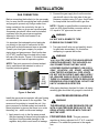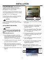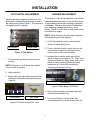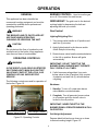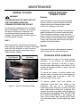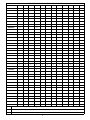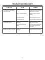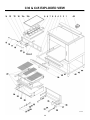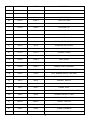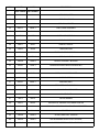
1
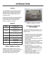
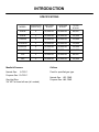
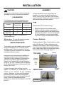
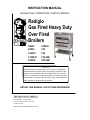
INSTRUCTION MANUAL INSTALLATION / OPERATIONS / PARTS & SERVICE Radiglo Gas Fired Heavy Duty Over Fired Broilers 36W36 243W36 43W36 C36 136W36 C45 V136W36 C36 SHB 236W36 C45 SHB NOTICE This Manual is prepared for the use of Service Technicians and should not be used by those not properly qualified. This manual is not intended to be all encompassing. You should read, in its entirety, the repair procedure you wish to perform to determine if you have the necessary tools, instruments and skills required to perform the procedure. RETAIN THIS MANUAL FOR FUTURE REFERENCE. THE MONTAGUE COMPANY 1830 Stearman Avenue P.O. BOX 4954 HAYWARD,CA 94549-4954 510.785.8822 FAX:510-785-3342 1-888-875-2722 WWW.MONTAGUECOMPANY.COM IMPORTANT FOR YOUR SAFETY THIS MANUAL HAS BEEN PREPARED FOR PERSONNEL QUALIFIED TO INSTALL GAS EQUIPMENT, WHO SHOULD PERFORM THE INITIAL FIELD START-UP AND ADJUSTMENTS OF THE EQUIPMENT COVERED BY THIS MANUAL. Qualified installation personnel are individuals, a firm, corporation, or company which either in person or through a representative are engaged in and are responsible for: A. The installation or replacement of gas piping or the connection, installation, repair or servicing of equipment, who is experienced in such work familiar with all precautions required, and have complied with all requirements of state or local authorities having jurisdiction. reference: National Fuel Gas Code, ANSI Z223.1, section 1.4, latest addenda. B. The installation of electrical wiring from the electric meter, main control box or service outlet to the electric appliance. Qualified installation personnel must be experienced in such work, be familiar with all precautions required and have complied with all requirements of state and local authorities having jurisdiction. Reference: National Electric Code, ANSI / NFPA No. 70, latest addenda. THE BROILER(S) MUST BE INSTALLED IN ACCORDANCE WITH LOCAL CODES, OR IN THE ABSENCE OF LOCAL CODES, WITH THE NATIONAL FUEL GAS CODE, ANSIZ223.1 LATEST ADDENDA, INCLUDING: The appliance and its individual shutoff valve must be disconnected from the gas supply piping system during any pressure testing of that system at test pressures in excess of 1/2 psig (3.45 kPa). The appliance must be isolated from the gas supply piping system by closing its individual manual shutoff valve during any pressure testing of the gas supply piping system at test pressures equal to or less than 1/2 psig (3.45 kPa) POST IN A PROMINENT LOCATION THE INSTRUCTIONS TO BE FOLLOWED IN THE EVENT THE SMELL OF GAS IS DETECTED. THIS INFORMATION CAN BE OBTAINED FROM THE LOCALGAS SUPPLIER. IN THE EVENT OF A POWER FAILURE, DO NOT ATTEMPT TO OPERATE THIS DEVICE. IMPORTANT IN THE EVENT A GAS ODOR IS DETECTED, SHUT DOWN UNITS AT MAIN SHUTOFF VALVE AND CONTACT THE LOCAL GAS COMPANY OR GAS SUPPLIER FOR SERVICE. FOR YOUR SAFETY DO NOT STORE OR USE GASOLINE OR OTHER FLAMMABLE VAPORS OR LIQUIDS IN THE VICINITY OF THIS OR ANY OTHER APPLIANCE. WARNING IMPROPER INSTALLATION, ADJUSTMENT, ALTERATION, SERVICE OR MAINTENANCE CAN CAUSE PROPERTY DAMAGE, INJURY OR DEATHL READ THE INSTALLATION, OPERATING AND MAINTENANCE INSTRUCTIONS THOROUGHLY BEFORE INSTALLING, SERVICING OR OPERATING THIS EQUIPMENT. INTRODUCTION GENERAL The Gas Broilers covered in this manual are manufactured for use with the type of gas indicated on the nameplate. Some models include a cabinet, conventional oven, or convection oven. Montague Gas Broilers are produced with the best possible material and workmanship. Proper installation is essential for safe, efficient, trouble-free operation. MODELS MODEL CONSISTS OF 36W36 Cabinet Based Broiler with Warming Oven 43W36 Cabinet Based Broiler with Warming Oven 136W36 Broiler with Conventional Oven and Warming Oven V136W36 Broiler with Convection Oven 236W36 Double Broiler 243W36 Double Broiler C36 Broiler Only C45 Broiler Only SERIAL NUMBER LOCATION Always have the serial number of your unit available when calling for parts and service. The serial number is on the nameplate that also includes the model number. A typical identification plate is shown in Figure 1. FIGURE1. TYPICAL I.D. PLATE RECEIVING & INSPECTING THE EQUIPMENT Care should be taken during unloading so the equipment is not damaged while being moved into the building. 1. Visually inspect the exterior of the package and skid or container. Any damage should be noted and reported to the delivering carrier immediately 2. If damaged, open and inspect the contents with the carrier. 3. In the event that the exterior is not damaged, yet upon opening, there is concealed damage to the equipment, notify the carrier. Notification should be made verbally as well as in written form. 4. Request an inspection by the shipping company of the damaged equipment. This should be done within 10 days from receipt of the equipment. 5. Freight carriers can supply the necessary damage forms upon request. 6. Retain all shipping materials until an inspection has been made or waived. INTRODUCTION SPECIFICATIONS # BURNERS NATURAL PROPANE (broilers only) BTU/HR BTU/HR 36W36 2 42,000 ea. 42,000 ea. 84,000 43W36 3 42,000 ea. 42,000 ea. 126,000 136W36 2 42,000 ea. 42,000 ea. 124,000 V136W36 2 42,000 ea. 42,000 ea. 129,000 236W36 4 42,000 ea. 42,000 ea. 168,000 243W36 6 42,000 ea. 42,000 ea. 252,000 C36 2 42,000 ea. 42,000 ea. 84,000 C45 3 42,000 ea. 42,000 ea. 126,000 MODEL TOTAL BTU/HR Manifold Pressure Orifices Natural Gas: 6.0‖W.C. Propane Gas: 10.0‖W.C. Fixed for specified gas type. Gas Inlet Size: 3/4‖ NPT at lower left rear (all models) Natural Gas: #33 DMS Propane Gas: #48 DMS TABLE OF CONTENTS INSTALLATION CLEARANCES. . . . . . . . . . . . . . . . . . . . . . . . . . . . . . . . . . . . . . . 1 VENTILATING HOOD. . . . . . . . . . . . . . . . . . . . . . . . . . . . . . . . . .1 ASSEMBLY. . . . . . . . . . . . . . . . . . . . . . . . . . . . . . . . . . . . . . . . . .1 LEGS. . . . . . . . . . . . . . . . . . . . . . . . . . . . . . . . . . . . . . . . . . . . 1 CERAMIC RADIANTS. . . . . . . . . . . . . . . . . . . . . . . . . . . . . . . 1 LEVELING . . . . . . . . . . . . . . . . . . . . . . . . . . . . . . . . . . . . . . . . . . 2 FLOOR INSTALLATION . . . . . . . . . . . . . . . . . . . . . . . . . . . . . 2 CURB INSTALLATION . . . . . . . . . . . . . . . . . . . . . . . . . . . . . . 2 GAS CONNECTION . . . . . . . . . . . . . . . . . . . . . . . . . . . . . . . . . . .3 GAS PRESSURE REGULATOR . . . . . . . . . . . . . . . . . . . . . . .3 GAS PRESSURE REGULATOR . . . . . . . . . . . . . . . . . . . . . . 4 PILOT . . . . . . . . . . . . . . . . . . . . . . . . . . . . . . . . . . . . . . . . . . .5 BURNER . . . . . . . . . . . . . . . . . . . . . . . . . . . . . . . . . . . . . . . . .5 OPERATION OPERATING CONTROLS. . . . . . . . . . . . . . . . . . . . . . . . . . . . . . 6 BURNER CONTROL . . . . . . . . . . . . . . . . . . . . . . . . . . . . . . . 6 GRID HEIGHT . . . . . . . . . . . . . . . . . . . . . . . . . . . . . . . . . . . . .6 GAS CONTROLS (LIGHTING PILOT). . . . . . . . . . . . . . . . . . .6 GAS CONTROLS (BURNER VALVE SHUTOFF). . . . . . . . . . 6 MAINTENANCE GENERAL CLEANING . . . . . . . . . . . . . . . . . . . . . . . . . . . . . . . . .7 PAINTED SURFACES. . . . . . . . . . . . . . . . . . . . . . . . . . . . . . . . . 7 EXTERIOR. . . . . . . . . . . . . . . . . . . . . . . . . . . . . . . . . . . . . . . .7 INTERIOR. . . . . . . . . . . . . . . . . . . . . . . . . . . . . . . . . . . . . . . . 7 STAINLESS STEEL SURFACES . . . . . . . . . . . . . . . . . . . . . . . . 7 REMOVE HEAT TINT . . . . . . . . . . . . . . . . . . . . . . . . . . . . . . .8 MAINTENANCE SCHEDULE. . . . . . . . . . . . . . . . . . . . . . . . . . . .9 PARTS REMOVAL AND REPLACEMENT PROCEDURES COVER & PANELS. . . . . . . . . . . . . . . . . . . . . . . . . . . . . . . . . . . .10 VENTURI COVER. . . . . . . . . . . . . . . . . . . . . . . . . . . . . . . . . . 10 CONTROL PANEL COVER. . . . . . . . . . . . . . . . . . . . . . . . . . .10 DRIP DEFLECTOR. . . . . . . . . . . . . . . . . . . . . . . . . . . . . . . . . 10 DRIP TRAY AND HORIZONTAL GREASE CONTAINER. . . .11 PILOT. . . . . . . . . . . . . . . . . . . . . . . . . . . . . . . . . . . . . . . . . . . . . . 11 PILOT ASSEMBLY & ORIFICE. . . . . . . . . . . . . . . . . . . . . . . . 11 BURNER. . . . . . . . . . . . . . . . . . . . . . . . . . . . . . . . . . . . . . . . . . . .12 BURNER ASSEMBLY . . . . . . . . . . . . . . . . . . . . . . . . . . . . . . .12 BURNER ORIFICE . . . . . . . . . . . . . . . . . . . . . . . . . . . . . . . . . 12 BURNER VENTURI . . . . . . . . . . . . . . . . . . . . . . . . . . . . . . . . 12 BURNER VALVES . . . . . . . . . . . . . . . . . . . . . . . . . . . . . . . . . . . .13 CARRIAGE POSITION HANDLE . . . . . . . . . . . . . . . . . . . . . . . . .14 BLACK BALL . . . . . . . . . . . . . . . . . . . . . . . . . . . . . . . . . . . . . .14 CHROME SLEEVE . . . . . . . . . . . . . . . . . . . . . . . . . . . . . . . . . 14 THREADED STUD . . . . . . . . . . . . . . . . . . . . . . . . . . . . . . . . . 14 GEAR & TUBE ASSEMBLY . . . . . . . . . . . . . . . . . . . . . . . . . . 14 COMPRESSION SPRING. . . . . . . . . . . . . . . . . . . . . . . . . . . . 14 GEAR & BRACKET . . . . . . . . . . . . . . . . . . . . . . . . . . . . . . . . .15 ADJUSTMENTS . . . . . . . . . . . . . . . . . . . . . . . . . . . . . . . . . . . . . .16 PRESSURE REGULATOR . . . . . . . . . . . . . . . . . . . . . . . . . . .16 PILOT BURNER . . . . . . . . . . . . . . . . . . . . . . . . . . . . . . . . . . . 16 CARRIAGE POSITION HANDLE . . . . . . . . . . . . . . . . . . . . . . 17 HANDLE TENSION . . . . . . . . . . . . . . . . . . . . . . . . . . . . . . . . .17 CARRIAGE TENSION SPRING . . . . . . . . . . . . . . . . . . . . . . . 17 TROUBLESHOOT CHART . . . . . . . . . . . . . . . . . . . . . . . . . . . . . 18 TROUBLESHOOT CHART . . . . . . . . . . . . . . . . . . . . . . . . . . . . . 19 C36 & C45 EXPLODED VIEW . . . . . . . . . . . . . . . . . . . . . . . . . . 20 C36 & C45 PART NUMBERS . . . . . . . . . . . . . . . . . . . . . . . . . . .21 C36 & C45 PART NUMBERS . . . . . . . . . . . . . . . . . . . . . . . . . . . 22 36W36 & 43W36 EXPLODED VIEW . . . . . . . . . . . . . . . . . . . . . .23 36W36 & 43W36 PART NUMBERS . . . . . . . . . . . . . . . . . . . . . . 24 36W36 & 43W36 PART NUMBERS . . . . . . . . . . . . . . . . . . . . . . 25 INSTALLATION ASSEMBLY CAUTION Provisions must be made to assure adequate air supply to unit for proper burner operation. Uncrate broiler as near to final location as possible. For easier and lighter handling of broiler, remove grids, grid frame, drip tray and grease container. Remove all packing materials and accessories from broiler interior. CLEARANCES The following are minimum clearances from combustible and noncombustible materials. Location Combustible Construction Noncombustible Back Wall 6‖ 0‖ Left Side 6‖ 0‖ Right Side 6‖ 0‖ Legs Construction Some broilers are mounted on legs. 1. Screw the legs into the modular stand. 2. Tightly screw the complete leg assembly into the mounting holes in the bottom of the broiler at each corner. If the unit is intended for curb installation, no legs are provided. The curb must be noncombustible material. With 6” legs: Suitable for installation on combustible floors. Ceramic Radiants Without legs: For use with special insulated base on noncombustible floors only. Ceramic radiants, Figure 2, are located on each side of the burners. Ceramic end pieces are installed at both ends of each burner assembly. Five (5) ceramic radiants are installed on each side of each burner with the pointed side facing sown and the holes facing up. Figure 3 VENTILATING HOOD The broiler(s) must be installed under a properly designed ventilating hood. The hood should extend at least 6‖ beyond all sides of the unit. The hood should be connected to an adequate mechanical exhaust system. TOP VIEW Information on construction and installation of ventilating hoods may be obtained from the ―Standard for the Installation of Equipment for the Removal of Smoke and Grease Laden Vapors from Commercial Cooking Equipment‖, NFPA No. 96-1987, available from the National Fire Protection Association, Batterymarch Park, Quincy, Ma. o2269. Frame Burner Ceramic Radiants 5 Each Side It is also necessary that sufficient room air ingress be allowed to compensate for the amount of air removed by the ventilating system. Otherwise, a subnormal atmospheric pressure will occur which may interfere with burner performance or may extinguish the pilot flame. In case of unsatisfactory broiler performance, check with the exhaust in the ―Off‖ position. FRONT VIEW FIGURE 2. 1 Ceramic Ends INSTALLATION BATTERY ARRANGEMENT Setting In Place Model No‖s 36W36, 43W36, 136W36, and V136W36. Floor Mounted Ranges Figure 3. Ceramic Radiants 1. Place the first unit in the exact position it will occupy in the battery. 1. Insert ceramic end pieces at front and rear of the burner frame. Four (4) are required for each burner. 2. Using a carpenter’s level, level the unit frontto rear and side –to– side. AN UNLEVELED UNIT WILL ADVERSELY AFFECT PERFORMANCE. Adjust as follows: 2. Tilt ceramic radiants sideways to clear burner and frame assembly, then lower radiant into position with one flange resting on burner ledge and one flange resting on frame edge. FLOOR INSTALLATION ON LEGS: Level by turning foot on leg. CURB INSTALLATION: Place shim under the low side. This operation is important since variations in floors and curbs are common. Unless units are level, aligning the gas supply manifold will be difficult and the units will not fit together tightly. 3. Install the remaining ceramic radiants so that five (5) ceramic radiants are located on each side of the burner. LOCATION 3. Remove the valve panel from the broiler. Adequate clearance for service and proper operation must be provided at the front, top, 4. Move the unit into position. sides, and back. The combustion air openings are provided in the front of the unit and must not 5. Engage union nut on manifold with male be obstructed. fitting on next unit and draw up union nut hand tight. Be sure appliances meet together both front and rear. If manifolds do not align, then units are not level. In extreme cases it LEVELING may be necessary to loosen manifold bolts and adjust. After broiler is positioned, check that appliance is level both side-to-side and front - to-back. 6. Continue leveling and connecting gas supply manifolds together until all appliances in battery are connected. 7. Tighten manifold gas union. Use backup wrench to prevent manifold from rotating. FAILURE TO DO THIS MAY RESULT IN DAMAGE TO THE PILOTS AND GAS VALVES. 2 INSTALLATION GAS CONNECTION 2. Connect the gas supply line from the service gas shutoff valve to the inlet side of the gas pressure regulator using 3/4‖ pipe. Avoid kinks Before connecting the broiler(s) to the gas supply or sharp bends that could restrict gas flow. line, be sure that all new piping has been cleaned and purged to prevent any foreign matter from NOTE: If flexible or semi-flexible connectors are being carried into the controls by the gas. In used, an AGA listed flexible connector with an some cases, filters or drops are recommended. I.D. equal to 3/4‖ pipe must be used. A separate gas shutoff valve must be installed upstream from the gas pressure regulator WARNING adjacent to the broiler and located in an accessible are. DO NOT USE A DOMESTIC TYPE FLEXIBLE GAS CONNECTOR. It is important that adequately sized piping be run directly to the point of connection at the broiler with as few elbows and tees as possible. Consult your local gas company for proper piping size and gas pressure. Each broiler has a 3/4‖ NPT manifold input located at the lower left rear of the broiler, Figure 4. On dual broilers, each broiler must have a separate regulator. 3. Turn gas shutoff valve on and carefully check for gas leaks immediately. Do this before attempting to operate the broiler. WARNING TEST ALL PIPE JOINTS FOR LEAKS BEFORE OPERATING BROILER. THIS INCLUDES ALL GAS CONNECTIONS THAT MAY HAVE LOOSENED DURING SHIPMENT. USE A RICH SOAP SOLUTION (OR OTHER ACCEPTED LEAK TESTER) AROUND ALL PIPE JOINTS. DO NOT USE AN OPEN FLAME. ABSOLUTELY NO LEAKAGE SHOULD OCCUR, OTHERWISE THERE IS A DANGER OF FIRE OR EXPLOSION DEPENDING UPON CONDITIONS. DO NOT USE UNIT IF LEAKAGE IS DETECTED. NOTE: Pipe joint compound or thread sealant that is used should be resistant to action of liquefied petroleum gases. 3/4‖ NPT GAS INLET After piping has been checked for leaks, all piping receiving gas should be fully purged to remove air. Figure 4. Gas Inlet GAS PRESSURE REGULATOR Install the gas pressure regulator with gas flowing as indicated by the arrow on the regulator. The WARNING arrow must be pointing in toward the unit. Use pipe compound or thread sealant and carefully THE BROILER(S) IS/ARE DESIGNED FOR USE thread regulator to pipe so that there is no cross WITH A GAS PRESSURE REGULATOR. THE threading, etc., which could cause leakage. REGULATOR(S) SUPPLIED WITH THIS UNIT MUST BE USED. 1. Apply wrench only to the flat areas around the pipe tapping at the end being threaded to FOR NATURAL GAS: This gas pressure the pipe to avoid possible damage to the regulator is factory adjusted for 6.0‖ W.C. manifold regulator body which could result in leakage. pressure. The rated inlet pressure to the regulators 3 INSTALLATION FOR PROPANE GAS: This gas pressure regulator is factory adjusted for 10.0‖ W.C. manifold pressure. The rated inlet pressure to the regulator is 1/2 psig (3.45 kPa). The broiler is equipped with fixed orifices for use with a manifold pressure of 6.0‖ W.C. for natural gas and 10.0‖ W.C. for propane gas. Position the gas pressure regulator outside the broiler as near to the unit as possible. Burner valve knobs CAUTION Screws Figure 5. Control Valve Knobs The gas pressure regulator must be located out of the heat zone to prevent damage to the regulator. 5. Remove the control valve panel by removing two screws. 6. Connect a manometer to the pressure tap provided on the broiler unit gas piping manifold, Figure 6. ADJUSTMENT PROCEDURE WARNING 7. Check the manometer reading. The reading must be 6.0‖ W.C. for natural gas, or 10.0‖ W.C. for propane gas. DO NOT ALLOW UNTRAINED PERSONNEL TO MAINTAIN OR SERVICE THE GAS PRESSURE REGULATOR. 8. If incoming line pressure is not correct, adjust the regulator. Remove the seal cap on the top of the regulator. 1. Before adjusting the regulator, check the incoming gas line pressure into the regulator. Incoming pressure must be 8.0‖ W.C. for natural gas, or 14‖ W.C. for propane gas. 9. Insert a blade-type screwdriver into the top hole of the regulator. 2. If incoming pressure is not correct, have the gas source checked and adjusted. 10. Turn the adjust screw clockwise to increase the pressure, or counter clockwise to decrease the pressure . 3. Make sure that the regulator is mounted in the horizontal position with the arrow pointing in the direction of the gas flow. While watching the manometer, turn the adjustment screw to set proper regulator outlet pressure to the manifold. 4. Remove the main burner control valve knobs, Figure 5. Manometer connection pressure tap Manifold Figure 6. Gas Pressure Tap 4 INSTALLATION PILOT INITIAL ADJUSTMENT BURNER ADJUSTMENT Each burner has a separate pilot burner. The pilot flame is adjusted through access holes in the valve control panel, Figure 7. Pilot access is through the broiler opening. The efficiency of the broiler depends on a delicate balance between the supply of air and the volume of gas at each main burner resulting in complete combustion. Whenever this balance is disturbed, poor operating characteristics occur. An air shutter, Figure 9, on the front of each main burner controls the air supply. NOTE: Pilots should be lit and properly adjusted before adjusting the main burners. 1. Lift off the manifold cover to access the air shutter for each main burner. Pilot Valves Valve Panel Figure 7. Pilot Valves 1. Turn the main gas shutoff valve to the on position. NOTE: Pilots are on at all times main shutoff valve is in the on position. 2. Turn on the main burner control valve for the main burner to adjust by rotating the main burner control valve fully clockwise. 3. Increase the air shutter openings until the flame on the burner begins to ―lift‖. Then close shutter until flame no longer floats, and lock in place. A yellow streaming flame indicates insufficient air. Correct this condition by increasing air shutter opening. 2. Light each pilot. 3. Adjust pilot valve adjustment screw so that each pilot burner has a steady blue flame, Figure 8. Air Shutters Adjustment Screw 1/2” 1/2‖ Pilot Burner Figure 9. Main Burner Air Shutter 4. After all main burners are properly adjusted, reinstall the manifold cover. Pilot Valve 5. Turn all main burner control valves fully counterclockwise to turn the main burner off. Figure 8. Pilot Burner and Pilot Valve 5 OPERATION GENERAL BURNER CONTROL: Used to turn the gas on or off. One control for each burner. This appliance has been classified as commercial cooking equipment and must be operated by qualified and/or professional operating personnel GRID HEIGHT: The grid is set to the desired cooking height by depressing the ball and adjusting the lever up or down. Gas Control WARNING THE BROILER AND ITS PARTS ARE HOT. USE CARE WHEN OPERATING. CLEANING OR SERVICING THE UNIT. Lighting/Relighting Pilot 1. Turn burner valve handle to off position and wait five (5) minutes. CAUTION 2. Apply lighted match to pilot burner and/or check that pilot is burning. Do not obstruct the flow of combustion and ventilation air to the broiler. Keep appliance area free and clear of combustibles. 3. Rotate burner valve handle counterclockwise to the full on position. Burner will ignite automatically. OPERATING CONTROLS WARNING IMPORTANT: DO NOT THROTTLE THE BURNER DOWN. BURNER MUST OPERATE FULLY OPEN AT ALL TIMES. IN THE EVENT A GAS ODOR IS DETECTED, SHUT DOWN UNITS MAIN GAS SHUTOFF VALVE AND CONTACT THE LOCAL GAS COMPANY OR GAS SUPPLIER FOR SERVICE.. 4. If pilot becomes extinguished, turn main burner valve to the off position (fully counterclockwise) and wait five (5) minutes before relighting. The following controls are used for operation of the broiler, Figure 10. Shutdown 1. Standby: To turn off, rotate main burner valve handles counterclockwise. 2. Complete: Turn all gas main burner valves to off position and turn shutoff valve to broiler to the off position. IMPORTANT: NEVER THROTTLE THE BURNER DOWN. OPERATE BURNER IN FULL ON POSITION. Burner Valve Knobs Grid Height Control Grid Height Adjustment Figure 10. Operating Controls Depress black ball and move lever up or down to desired cooking height. Figure 10. 6 MAINTENANCE GENERAL CLEANING PAINTED SURFACES/ POWDER COATED Exterior WARNING THE BROILER AND ITS PARTS ARE HOT. USE CARE WHEN OPERATING, CLEANING OR SERVICING THE UNIT. Allow the broiler to cool down before cleaning exterior surfaces. Painted surfaces should be cleaned using a mild soap and warm water solution on a sponge or soft cloth. Lint and grease suspended in the air tend to collect in passages. Therefore, air openings, flue ways, and primary air openings, etc., should be periodically cleaned to prevent clogging. The entire broiler should be given a periodic general cleaning. Powder Coat, Copper, and other such painted or plated finishes are not covered under warranty. These finishes are subject to wear and may begin to discolor and/or chip within a short period of time. Caution should be taken when cleaning. Using a mild soap and water solution will help to maintain the look and finish. DAILY Remove grid racks, drip deflector (below grid Interior rack), drip tray, and grease container. Thoroughly wash with mild detergent or soap. Excessive Clean interior using a mildly abrasive cleanser grease buildup may be removed by using a with a damp cloth or nylon cleaning pad. mildly abrasive cleanser. Drip Deflector STAINLESS STEEL SURFACES Grid Rack Stainless steel is an alloy of iron which contains chromium. In the process of manufacturing stainless steel, chromium in the alloy is used to form the hard oxide coating on the surface. If this is taken off through corrosion or wear, it will rust like regular steel. To remove dirt, grease or product residue from stainless steel, use water and a mild detergent if needed, applied with a sponge or cloth. Dry thoroughly with a clean cloth. Grease Container Drip Tray To remove grease and food splatter, or condensed vapors that have baked on the equipment, you can use a (non-abrasive) commercial cream cleanser or baking soda and water, applied with a damp cloth or sponge. Rub cleanser as gently as possible (with the grain) in the direction of the polished lines. DO NOT RUB IN A CIRCULAR MOTION, it will damage the finish. Rinse surface after cleaning with a damp cloth and clean water. Dry thoroughly with clean cloth. Figure 11. Items To Be Cleaned Daily 7 MAINTENANCE Drying thoroughly will prevent water spots which are harmful to the finish. CLEANING: HELPFUL HINTS: To remove streaks, rub stainless steel surface with olive oil. To clean and polish, simply moisten a cloth with undiluted white or cider vinegar and wipe clean. Vinegar can also be used to remove heat stains. Oil from fingerprints can etch or tarnish stainless steel, especially mirror-polished finishes. Wherever stainless steel is visible , use a glass cleaner to remove fingerprints at the end of the day, before the finish is permanently damaged. GRIDDLE / PLANCHA SEASONING: After each use, scrape griddle clean with a griddle scraper when cooked food is removed to keep surface free of encrusted material and also prevent flavor transfer. After each day, while griddle is warm, clean surface with a griddle stone using a back and forth motion. For stainless steel, rub in the direction of the grain to not damage the surface. Clean grease trough thoroughly and empty grease container. Weekly, Allow griddle to cool completely and clean plate with a foodservice grade degreaser. Re-season griddle as needed, or apply a coating of cooking oil to prevent rust. A mixture of lemon juice and carbonated (soda) water can also be used while the griddle is warm. After applying mixture, rub griddle stone back and forth to clean surface. Dry thoroughly and re-season if needed, or apply a coating of cooking oil to prevent rust. Seasoning refers to the process of oil or lard being baked into the metal to create a non-stick *NOTE - See page 9 for complete maintenance schedule of unit. surface for cooking on a new or recently cleaned griddle. If a griddle has been seasoned and food begins to stick, you should re-season your griddle. To season follow these steps: Turn griddle on to a low setting (around 300 degrees F ) for about 45 mins. to 1 hour. Using a lint-free cotton cloth, apply a generous coat of cooking grade oil or hydrogenated shortening across the entire surface of the griddle. Apply additional layers until surface is slick and oil no longer seeps into griddle. Increase heat on griddle to 350-400 degrees F. Once griddle reaches temp turn griddle off and let cool. Wipe off excess oil with lint-free cotton cloth. 8 OVERFIRED BROILER MAINTENANCE SCHEDULE COMPONENTS JAN T-COUPLE (CE) 1,3,4 1,3,4 1,3,4 1,3,4 INJECTORS 1,2 1,2 1,2 1,2 GASKETS 1,4 1,4 1,4 1,4 BEARINGS 1,4 1,4 1,4 1,4 PILOT 1,2 VALVE (CE) 1,5 GRID IRON * 2 BURNERS 1,2 TOP PLATE * 2 AIR MIXER 1,2 GREASE CONT. * 2 INTERIOR 2 2 2 2 GEAR MECH. 1,5 1,5 1,5 1,5 REGULATOR 1,2 1,2 1,2 1,2 CERAMICS 1,2,4 1,2,4 1,2,4 1,2,4 DRIP TRAY * 2 1. CHECK 2. CLEAN 3. ADJUST 4. REPLACE 5. LUBRICATE FEB MAR APRIL 1,2 MAY JUNE 1,2 2 2 AUG 1,2 1,5 2 JULY 1,5 2 2 2 2 2 2 2 2 2 2 2 2 2 2 2 2 2 *NOTE* Maintenance schedule may vary due to the gas heating value per country. *NOTE* Lack of maintenance may result in pre-mature failure of components. *NOTE* Parts marked with an * should be cleaned daily. 9 DEC 1,2 1,5 2 2 2 2 2 2 2 2 2 2 1,2 2 NOV 1,2 1,2 2 OCT 1,2 1,2 2 SEPT 2 1,2 2 2 2 2 2 2 2 2 2 2 PARTS REMOVAL & REPLACEMENT PROCEDURES Perform the following procedures to remove and 1. Turn the control valves to the full off position, then remove the control valve knobs. replace parts. To eliminate mistakes when ordering parts, always provide the following 2. Remove the two screws from the front of the control information: panel. Model Number Serial Number These numbers are located on the nameplate. CAUTION Turn off the broiler gas valve and allow broiler to cool before removing any components CONTROL VALVE KNOB FIGURE 2. CONTROL PANEL COVER COVER & PANELS DRIP DEFLECTOR CAUTION Turn off the gas supply at the manual shutoff valve that is next to the broiler before attempting to loosen any gas connections. SCREWS The drip defector is located below the grid frame and is angled toward the back of the broiler. Grease dripping onto the drip deflector runs off the back edge to the drip tray then flows forward into the horizontal grease container. Venturi Cover 1. Pull the grid frame assembly forward to the stop. Removal of the venture cover provides access to 2. Remove the grids from the frame assembly. the air shutter adjustments and main burner 3. Lift the back edge of the drip deflector to disorifices. engage the drip deflector from the retaining latch. Remove the two screws under the front edge of the venture cover. 4. Slide the drip deflector out at a downward angle. 2. Lift the venture cover from the broiler. 5. When reinstalling the drip defector, be sure to VENTURI COVER screw screw engage the front end under the retaining latch. FIGURE 1. VENTURI COVER Drip deflector Retaining Latch Control Panel Cover Grid Frame Removal of the control panel cover provides access to the burner valves, pilot adjustment FIGURE 3. DRIP DEFLECTOR 10 PARTS REMOVAL AND REPLACEMENT PROCEDURES DRIP TRAY AND HORIZONTAL GREASE CONTAINER The drip tray is located below the drip deflector. Grease dripping onto the drip deflector runs off the back edge to the drip tray then flows forward into the horizontal grease container. 1. Pull the drip tray straight out the front of the broiler. 2. Lift the horizontal grease container up and away from the broiler. NOTE: When dumping the contents of the horizontal grease container, be sure to follow appropriate regulations for disposing of grease. NOTE: Make sure that the pipe joint compound or pipe thread sealant that is being used is resistant to the corrosive actions of liquefied petroleum gases. 5. Connect the gas line to the back of the valve. 6. Turn the main gas shutoff valve to broiler to the ON position. WARNING ALL GAS JOINTS DISTRUBED DURING SERVICING MUST BE CHECKED FOR LEAKS. CHECK WITH A SOAP AND WATER SOLUTION(BUBBLES). DO NOT USE AN OPEN FLAME. 7. Light pilot and adjust pilot valve. 8. Reinstall control panel cover and control valve knobs. Horizontal Grease Container Drip Tray Figure 4. Drip Tray & Grease Container PILOT Adjustment Valve The pilot adjustment valves are located on the manifold behind the control panel cover. CAUTION Turn off the gas supply at the manual shutoff valve that is next to the broiler before attempting to loosen any gas connections. 1. Remove the control panel cover as described under Covers and Panels to access the pilot valve. 2. Disconnect the gas line from the back of the valve. 3. Unscrew the pilot valve from the manifold. 4. Install the new pilot valve with the adjustment screw facing the front of the broiler. Gas Line Manifold Pilot Valve Figure 5. Pilot Valve Pilot Assembly and Orifice The pilot assembly is located adjacent to each burner. The connection for the pilot assembly is accessed by removing the venturi cover. CAUTION 1. Remove the venturi cover as described in COVERS AND PANELS. 2. Disconnect gas line from back of pilot assembly. 3. Unscrew the two screws attaching the pilot assembly and pilot assembly bracket. NOTE: Check condition of the pilot orifice and replace if damaged. 11 PARTS REMOVAL AND REPLACEMENT PROCEDURES 4. Install the new pilot assembly, orifice and pilot assembly bracket. 5. Connect the gas line to the back of the pilot assembly. MAIN BURNERS 6. Turn the main gas shutoff valve to the broiler to the ON position. Turn off the gas supply at the main shutoff valve that is next to the broiler before attempting to loosen any gas connections. The connection for the burners is accessed by removing the venturi cover. The burners are accessed by removing the grids and carriage. NOTE: Make sure that the pipe joint compound The burner valves are accessed by removing the or pipe thread sealant that is being used control panel cover. is resistant to the corrosive actions of liquefied petroleum gases. CAUTION WARNING Burner Assembly, Orifice and Venturi ALL GAS JOINTS DISTURBED DURING SERVICEING MUST BE CHECKED FOR 1. Remove the venturi cover as described in COVERS & PANELS. LEAKS. CHECK WITH A SOAP AND WATER SOLUTION (BUBBLES). DO NOT USE AN 2. Remove the ceramic radiants from each side of the main burner to be replaced. OPEN FLAME. 3. Loosen the set screw that attaches the main burner to the venturi assembly. 7. Light pilot and adjust pilot valve. 8. Reinstall venturi cover, heat shield, insulation 4. Slide the main burner out of the broiler. 5. If the venturi or orifice is to be replaced, and exterior top. disconnect the gas input to the venturi. Remove the gasket. Replace the gasket every time the venturi or burner is removed. 6. Loosen the lock nut so that the venturi can Gas be removed from the bracket. Line Set Screw Pilot Brkt. Assy. Gasket Lock Nut Gas Input Bracket Screws Figure 6. Pilot Assembly Connection Venturi Figure 8. Burner Pilot Assembly 7. Remove the orifice hex nut fitting from the venturi. 8. Remove the orifice from the hex nut fitting. Pilot Assembly & Orifice Figure 7. Pilot Assembly 12 PARTS REMOVAL & REPLACEMENT PROCEDURE 9. Reassemble by reversing procedure. WARNING 5. Connect the gas line to the back of the valve. 6. Turn the main gas shutoff valve to the broiler to the ―ON‖ position. WARNING ALL GAS JOINTS DISTURBED DURING SERVICING MUST BE CHECKED FOR LEAKS. ALL GAS JOINTS DISTURBED DURING CHECK WITH A SOAP AND WATER SERVICING MUST BE CHECKED FOR LEAKS. SOLUTION (BUBBLES). DO NOT USE AN CHECK WITH A SOAP AND WATER OPEN FLAME. SOLUTION (BUBBLES). DO NOT USE AN OPEN FLAME. 7. Light pilot. 8. Reinstall the control panel cover and control valve knobs. 9. Turn burner valve full on and check that burner is properly lit. Orifice Orifice Hex fitting Bracket Figure 9. Orifice Assembly Burner valve The burner valves are located on the manifold behind the control panel cover. Burner Valves Figure 10. Burner Valve CAUTION Turn off the gas supply at the manual shutoff valve that is next to the broiler before attempting to loosen any gas connections. 1. Remove the control panel cover as described under COVERS & PANELS to access the burner valve. 2. Disconnect the gas line from the back of the burner valve. 3. Unscrew the burner valve from the manifold. 4. Install the new burner valve. NOTE: Make sure that the pipe joint compound or pipe thread sealant that is being used is resistant to the corrosive actions of liquefied petroleum gases. 13 PARTS REMOVAL AND REPLACEMENT PROCEDURE Threaded Stud CARRIAGE POSITION HANDLE The carriage position handle consists of the parts 1. Turn off the burners. 2. Allow the broiler to cool to room temperature. shown in the following illustration and parts list. 3. Remove the black ball knob by unscrewing it (counterclockwise) from the threaded stud. 4. Remove the chrome sleeve from the tube/ threaded stud assembly. 5. Unscrew the threaded stud from the tube. 6. Reinstall the threaded stud by performing the above steps in reverse order. Screw the E F B A threaded stud about 1‖ into the threaded end C D of the tube. Figure 11. Carriage Position Handle Gear and Tube Assembly Item Part # Description Qty. A 02033-8 Knob, Black Ball 1 B 32756-5 Compression Spring 1 C 03503-3 Gear and Tube Assembly 1 D 03506-8 Stud, Threaded 1 E 03504-1 Sleeve, Chrome 1 F 14442-8 Handle Bracket 1 1. Turn off burners. 2. Allow the broiler to cool to room temperature. 3. Remove the black ball knob by unscrewing it (counterclockwise) from the threaded stud. 4. Remove the chrome sleeve. 5. Remove gear with bracket from the cabinet frame. 6. Slide the gear and tube assembly off the carriage position handle arm. 7. Replace the gear and tube assembly by performing the above steps in reverse order. Black Ball Knob 1. Remove the black ball knob by unscrewing it (counterclockwise) from the threaded stud. 2. Replace the black ball knob by screwing it (clockwise) onto the threaded stud. Compression Spring 1. Turn off burners. 2. Allow the broiler to cool to room temperature. 3. Remove the black ball knob by unscrewing it (counterclockwise) from the threaded stud. 4. Remove the chrome sleeve. 5. Remove the threaded rod. 6. Remove the spring from the tube and gear assembly using needle nose pliers. 7. Replace the compression spring by performing the above steps in reverse order. Chrome Sleeve 1. Turn off the burners. 2. Allow the broiler to cool to room temperature. 3. Remove the black ball knob by unscrewing it (counterclockwise) from the threaded stud. 4. Remove the sleeve from the tube / threaded stud assembly. 5. Replace the chrome sleeve by placing the sleeve onto the threaded stud. 14 PARTS REMOVAL AND REPLACEMENT PROCEDURES Gear with Bracket 1. 2. 3. 4. Turn off the burners. Allow the broiler to cool to room temperature. Raise grill to the top. Remove all components of carriage position handle. 5. Remove the two screws and nuts that hold the gear with bracket to the vertical frame rail. 6. Replace the gear with bracket by performing the above steps in reverse order. Gear With Bracket SCREW Figure 12. Gear with Bracket Assembly 15 SERVICE & ADJUSTMENT PROCEDURES When service is needed, contact a local service company, dealer, or factory to perform mechanical maintenance and repairs. These instructions are intended for use by competent service personnel. CAUTION Turn off the gas supply at the manual shutoff valve that is next to the broiler unit before attempting to loosen any gas connections. GAS PRESSURE REGULATOR ADJUSTMENT PROCEDURE 7. Insert a blade-type screwdriver into the top hole of the regulator. 8. Turn the adjustment screw clockwise to increase the pressure, or counterclockwise to decrease the pressure. 9. While watching manometer, turn the adjustment screw to set proper Regulator outlet pressure. PILOT BURNER ADJUSTMENT PROCEDURE WARNING DO NOT ALLOW UNTRAINED PERSONEL TO 1. Light the pilot burner as described in the MAINTAIN OR SERVICE THE GAS PRESSURE Installation and Operation Manual. REGULATOR. Pilot Burner 1/2‖ Seal Cap Adjustment Screw 1/2‖ Figure 14. Pilot Burner and Adjustment Valve To Broiler 2. If the pilot burner flame burns yellow, clean the pilot burner orifice and the pilot burner in order to ensure a steady blue flame. The orifice can be cleaned by washing it in a 1. Before adjusting the regulator, check incoming solvent such as trichloroethylene and/or gas line pressure. Incoming pressure before blowing out with air. the regulator must be 6.0‖W.C. for Natural 3. If the pilot burner flame still burns yellow, Gas, or 14.0‖W.C. for Propane Gas. replace the pilot burner orifice. 2. If incoming pressure is not correct, have the 4. If the pilot flame does not extend 1/2‖ beyond gas source checked and adjusted as the outer edges of the pilot shield, or if it necessary. extends more than 1/2‖ beyond the outer 3. Make sure that the regulator is mounted in the edges of the pilot shield, an adjustment is horizontal position with the arrow pointing in necessary. the direction of the gas flow. 5. Remove the control panel cover as described 4. Connect a monometer to the pressure tap in COVERS AND PANELS. provided on the manifold between the 6. Turn the pilot adjustment valve screw until regulator and the burner valves. 1/2‖ flames are observed. 5. Check the manometer reading. The reading must be 6.0‖W.C. for Natural Gas, or 10.0‖ W.C. for Propane Gas. 6. If incoming line pressure is not correct, adjust the regulator. Remove seal cap on top of the regulator. Figure 13. Gas Pressure Regulator 16 SERVICE AND ADJUSTMENT PROCEDURES CARRIAGE POSITION HANDLE ADJUSTMENT PROCEDURE The carriage position handle can be placed in a number of vertical positions. CARRIAGE TENSION SPRING ADJUSTMENT PROCEDURE Carriage adjustments should be made with grid irons in place and allowance for product weight. 1. Grasp the black ball knob and press it in toward the front control panel. 2. Raise or lower the carriage assembly to the desired height. 3. Release pressure on the black ball knob to lock the carriage assembly at the desired height. TURN NUT CLOCKWISE TO RAISE 2 Carriage tension spring adjustment nut 1 Figure 16. Carriage Tension Spring Figure 15. Carriage Position Handle HANDLE TENSION ADJUSTMENT If carriage is difficult to move or will not stay in place, the handle tension requires adjusting. Carriage tension spring 1. Locate the carriage tension spring adjustment nut. The adjustment nut is accessible from the front as follows: Model #’s 36W36 and 43W36: Through lower compartment. 1. Remove black ball knob and chrome sleeve. 2. Turn threaded rod to the left to increase tension; turn to the right to decrease tension. Model #’s 136W36 and V136W3 Behind Valve Panel Model #’s C36, C45, 236W36 and 243W36 Behind left and right front panels. 2. Turn nut clockwise to increase tension or counterclockwise to decrease tension. 3. If one side of the grid is lower than the other side, turn the adjustment nut on the low side clockwise to level the grid. 17 TROUBLESHOOTING CHART SYMPTOM Pilot burner flames are burning yellow CAUSE REMEDY Gas too rich Perform the Pilot Burner Adjustment Procedure Clogged pilot air passages Perform the Pilot Burner Orifice Removal and Replacement Procedure. Pilot not properly adjusted Perform the Pilot Adjustment Valve Adjustment Procedure. Pilot burner flames are less than Pilot not properly adjusted or more than 1/2‖ Clogged pilot burner One or more pilot burner flames Faulty pilot burner or orifice Cannot be adjusted. Perform the Pilot Burner Adjustment Procedure. Replace pilot burner. Perform the Pilot Burner Removal and Replacement Procedure or Orifice Removal And Replacement Procedure as Applicable. Faulty pilot valve Perform the Pilot Burner Valve Removal and Replacement Procedure. Burner flames burning yellow Incorrect gas pressure or secondary air. Check gas pressure. Adjust or Clean air mixer. One or more burner flames Cannot be adjusted. Dirty Venturi passage Perform the Main Burner Orifice Removal and Replacement Procedure Incorrect gas pressure Check and adjust gas pressure. Ceramics cracked, broken or Missing. Replace damaged or missing Ceramics. See Installation & Operation Manual. Faulty burner valve. Perform the Main Burner Removal and Replacement Procedure. 18 TROUBLESHOOTING CHART SYMPTOM CAUSE The heat of one or more burners Clogged burner ports is not uniform over the surface of the ceramic tiles. Carriage assembly will not stay at a set height position. REMEDY Clean burner ports or perform The Main Burner Removal and Replacement Procedure. Broken or missing ceramics Replace broken or missing ceramics. Dirty venturi passage Clean air mixer and venturi. Wrong gas pressure Check and adjust gas pressure. Improper handle spring tension Adjustment Perform the Handle Tension Adjustment Procedure. Worn or broken gear with bracket Perform the Gear with Bracket Removal and Replacement Procedure. Carriage assembly moves up Improper carriage spring tension Perform the Carriage Tension Spring Adjustment Procedure. and down too easily or too hard. Adjustment. 19 C36 & C45 EXPLODED VIEW 20 ITEM PART # PART # DESCRIPTION C36 & 236W36 C45 & 243W36 1 12925-9 12925-9 PANEL, RIGHT SIDE 2A 25442-8 25442-8 FLUE, RIGHT SIDE 2B 25440-1 25440-1 FLUE, LEFT SIDE 2C 12610-1 15391-5 FLUE DEFLECTOR 3 15355-9 15385-0 EXTERIOR TOP 4 12923-2 12923-2 PANEL, LEFT SIDE 5 1100-2 1100-2 MANIFOLD 6 15367-2 15392-3 VALVE CONTROL PANEL 7 15211-0 15211-0 FRAME, BURNER ASSEMBLY 8 3511-4 3511-4 BURNER W/ SET SCREW 9 11614-9 11614-9 INSULATOR, CERAMIC 10 11611-4 11611-4 CERAMIC, LARGE 10A 28387-8 28387-8 CERAMIC KIT(10 ea. 11611-4) (4 ea. 11614-9) 11A 15352-4 15383-4 HEAT SHIELD 11B 1430-3 1430-3 INSULATION 12 15182-3 15295-1 FIREBOX FRONT ASSEMBLY 13A 11769-2 11769-2 PILOT BURNER HEX COMPRESSION FITTING 13B 2193-8 2193-8 PILOT BURNER ORIFICE—NATURAL 13C 2194-6 2194-6 PILOT BURNER ORIFICE—PROPANE 14 3397-9 3397-9 BRACKET, ORIFICE 15 1280-7 1280-7 UNION, TUBING 16 1252-1 1252-1 TUBING, STEEL 17 6378-9 6378-9 BURNER, ORIFICE HEX COMPRESSION FITTING 18A 4342-0 4342-0 BURNER, ORIFICE– LP #49 18B 17130-1 17130-1 BURNER, ORIFICE– NAT #32 19 20923-6 20923-6 GASKET, VENTURI 20 15216-1 15216-1 VENTURI, AIR MIXER ASSEMBLY 21 1224-6 1224-6 TUBING, ALUMINUM 22 3396-0 3396-0 BEARING, W/ ASSEMBLY 21 ITEM PART # PART# DESCRIPTION C36 & 236W36 C45 & 243W36 23A 1601-2 1601-2 GRID IRON, LEFT 23B 1600-4 1600-4 GRID IRON, RIGHT 23C N/A 1602-0 GRID IRON, CENTER 24 38331-7 38040-7 GRID FRAME ASSEMBLY 25 2549-1 3548-3 DRIP DEFLECTOR 26 4655-8 4657-4 CARRIAGE ASSEMBLY 27 2033-8 2033-8 KNOB, BLACK BALL 28 3504-1 3504-1 HANDLE, SLEEVE 29 3506-8 3506-8 THREADED ROD 30 3503-3 3503-3 TUBE AND GEAR ASSEMBLY 31 32756-5 32756-5 SPRING, HANDLE 32 14442-8 14442-8 HANDLE ASSEMBLY BRACKET 33 15244-7 15244-7 CARRIAGE SPRING MOUNTING BRACKET 34 1938-0 1938-0 EYE BOLT 35 3507-6 3507-6 GEAR, W/ ANGLE BRACKET 36 34258-0 2034-6 CARRIAE SPRING 37 28365-7 28365-7 CARRIAGE BOLT 38 13096-6 13101-6 STABILIZER UNIT ASSEMBLY 39 2002-8 2002-8 VALVE HANDLE W/ SET SCREW 40 1000-6 1000-6 VALVE, PILOT 41 1007-3 1007-3 VALVE, BURNER 42A 6604-4 6604-4 HORIZONTAL GREASE CONTAINER-PAINTED 42B 6603-6 6603-6 HORIZONTAL GREAE CONTAINER– STAINLESS STEEL 43 15246-3 15366-4 DRIP TRAY 44 13064-8 13056-6 STAND, MODULAR– PAINTED 45A 14605-6 14605-6 GAS PRESSURE REGULATOR– NATURAL 45B 1040-5 1040-5 GAS PRESSURE REGULATOR– PROPANE 22 NOTES 36W36 & 43W36 EXPLODED VIEW 23 ITEM PART # PART # DESCRIPTION 36W36 43W36 1 15168-8 15287-0 PANEL, BACK & SIDE 2 15233-1 32069-2 FALSE TOP, FRONT 3A 15238-2 32075-7 FLUE, LEFT SIDE 3B 15239-0 32076-5 FLUE, RIGHT SIDE 4 15232-3 15232-3 FALSE TOP, FRONT 5 15609-4 31642-3 DOOR ASSEMBLY 6 3173-9 3173-9 HANDLE 7 15187-4 15305-2 GUARD RAIL ASSEMBLY 8 6137-9 6137-9 VALVE BRACKET 9 1073-1 15303-6 MANIFOLD 10 3544-0 3544-0 BURNER FRAME ASSEMBLY 11 3511-4 3511-4 BURNER W/ HARDWARE 12 11614-9 11614-9 CERAMIC INSULATOR 13 11611-4 11611-4 CERAMIC, LARGE 13A 28387-8 28387-8 CERAMIC KIT (4 ea. 11614-9) (10 ea. 11611-4) 14 15359-1 15359-1 HEAT SHIELD 15 15223-4 31645-8 OVEN BOTTOM LINER 16 1604-7 1579-2 WIRE RACK 17 15182-3 15295-1 FIRE BOX FRONT ASSEMBLY 18A 11769-2 11769-2 PILOT BURNER ASSEMBLY– NATURAL 18B 15432-6 15432-6 PILOT BURNER ASSEMBLY– PROPANE 18C 2193-8 2193-8 PILOT ORIFICE– NATURAL 18D 2194-6 2194-6 PILOT ORIFICE– PROPANE 19 3397-9 3397-9 ORIFICE BRACKET ASSEMBLY 20 1280-7 1280-7 UNION, TUBING 21 1252-1 1252-1 TUBING, STEEL 22 6378-9 6378-9 HEX COMPRESSION FITTING ASSEMBLY 23A 6377-0 6377-0 BURNER ORIFICE-NATURAL 23B 2278-0 2278-0 BURNER ORIFICE– PROPANE 24 20923-6 20923-6 GASKET, VENTURI 24 ITEM PART # PART # DESCRIPTION 36W36 43W36 25 15216-1 15216-1 VENTURI 26 1231-9 1231-9 TUBING, ALUMINUM 27A 1601-2 1601-2 GRID IRON– LEFT 27B N/A 1602-0 GRID IRON– CENTER 27C 1601-2 1601-2 GRID IRON– RIGHT 28 3396-0 3396-0 BEARING ASSEMBLY 29 32376-4 38040-7 GRID FRAME ASSEMBLY WITH BEARINGS 30 3547-5 3548-3 DRIP DEFLECTOR 31 4660-4 4661-2 CARRIAGE ASSEMBLY 32 2033-8 2033-8 KNOB, BLACK BALL 33 3504-1 3504-1 SLEEVE 34 3506-8 3506-8 THREADED ROD 35 3503-3 3503-3 TUBE & GEAR ASSEMBLY 36 23753-1 23753-1 SPRING, HANDLE 37 14442-8 14442-8 HANDLE ASSEMBLY BRACKET 38 15244-7 15244-7 BRACKET, CARRIAGE SPRING 39 1938-0 1938-0 EYE BOLT 40 34258-0 2034-6 CARRIAGE SPRING 41 3507-6 3507-6 GEAR W/ ANGLE BRACKET 42 28365-7 28365-7 CARRIAGE BOLT 43 13108-3 13109-1 STABALIZER UNIT ASSEMBLY 44 1000-6 1000-6 PILOT VALVE 45 1007-3 1007-3 VALVE 46 15267-6 15333-8 PANEL, VALVE CONTROL 47 38485-2 38485-2 HANDLE, VALVE, W/ SET SCREW 48A 14605-6 14605-6 REGULATOR, GAS PRESSURE– NATURAL 48B 1040-5 1040-5 REGULATOR, GAS PRISSURE– PROPANE 49 4291-9 4291-9 GREASE DRAWER, 14‖ X 26 1/2‖ X 4 25 WARNING If not installed, operated and maintained in accordance with the manufacturers instructions, this product could expose you to substances in fuel or in fuel combustion which can cause death or serious illness and which are known to the State of California to cause cancer, birth defects or other reproductive harm. The State of California enacted the California Safe Drinking Water and Toxic Enforcement Act of 1986, (Prop. 65), which ―prohibits any person In the course of doing business from knowingly and intentionally exposing any individual to a chemical known to the State of California to cause cancer or reproductive toxicity without first giving clear and reasonable warning to such individuals.‖ The Governor’s Scientific Advisory Panel added carbon monoxide to the list of hazardous chemicals known to cause reproductive harm. In order to establish full compliance with Proposition 65, we attached a yellow warning label to each gas fired unit manufactured by the Montague Company. Carbon monoxide would not be present in concentrations that would pose a ―significant risk‖ to the consumer when the equipment is installed, operated and maintained as follows: 1. Installed in accordance with all local codes, or in the absence of local codes, with the current National Fuel Gas Code Z223.1, Latest Addendum. 2. Installed under a properly designed and operating exhaust hood. 3. Connected to the type of gas for which the unit is equipped. 4. Proper appliance pressure regulator installed on the gas supply line and adjusted for the manifold pressure marked on the rating plate. 5. Adequate air supply to the unit. 6. The equipment is operated in the manner intended using the proper utensil for that type of appliance. 7. Keep the equipment clean and have it checked periodically. 8. Burner air adjustments, mechanical maintenance and repairs should be performed by qualified service personnel. All PERSONNEL IN THE WORKPLACE WHO MAY BE SUBJECT TO ANY EXPOSURE OF CARBON MONOXIDE MUST BE WARNED OF SUCH POSSIBLE EXPOSURE. THIS WARNING SHOULD BE CONVEYED IN A MANNER SO THAT IT IS CLEARLY UNDERSTOOD BY THE EMPLOYEE, AND THE EMPLOYEE SHOULD BE ASKED IF IN FACT HE OR SHE UNDERSTANDS THE CORRECT METHOD OF OPERATION OF THE EQUIPMENT AND THAT A RISK OF EXPOSURE EXISTS IF THE EQUIPMENT IS OPERATED IMPROPERLY. P/N 40583-3 RD 4/13