1
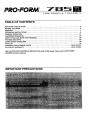
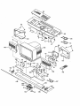
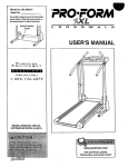
PRO'FORM
78
®
LOW
PROFILI_
TREADMILL
SEARS
Model No. 831.297860
Serial No.
-
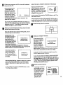
The serialnumberisfound Inthe location
shownbelow. Writethe sedatnumberin
the spaceabovefor futurereference.
_-" X
EOUI
i=- R C I S
PMENT
It,,] ]IllE:E,,.'_
Illi
II
E;
[ei_EE;
HELPLINE!
t_00-
7 36-687
9
USER'S MANUAL
PRO.FORM
7
LOW
5
PROFILE
im
TREADMILL
TABLE OF CONTENTS
IMPORTANT PRECAUTIONS .................................................................
BEFORE YOU BEGIN .......................................................................
ASSEMBLY .......................................
_........,......o..............°-.o.°*--7
GROUNDING INSTRUCTIONS
.......................
_..°°...°.oo.o....o°°...°oo.oo..°*-o._.•9
CONSOLE O.PERATION ............................
TELEVISION OPERATION
..........................
HOW TO FO_D AND MOVE THE TREADMILL
TROUBLE-SHOOTING
.............................
CONDITIONING GUIDELINES.
......................
2
6
.°.
o..o°.o..,°°,....°.°..°oo
..........
PART LIST ......
. ..................................
ORDERING REPLACEMENT PARTS .............
.. ...
FULL 90 DAY WARRANTY
........................................................
•
.°o..•l,....o.°o°o°°-°
°oo,.
e,
°o°°
• °°...°.
o°o..
• .°°.°..,
.°
=o.°.o..,o.........°....o.°.
•
J,
...°
,t,
°o°
,...,.o.o..°.o.°°,°°.
DRAWING for future reference.
PRECAUTIONS
•
._
..
..o.o.o..°.......'....*-.
*
•
.................
. ....
o .....
..°23
...25
...28
30
BACKCOVER
BACK COVER
Note: An EXPLODED DRAWING is attached to the center of this manual. Please save the EXPLODED
IMPORTANT
...10
...16
......,....,.,.......°.o.,,,.,,o.,,.
•:
8.
:.....
.19. Do not operate
•
kg) .
ever
migl _
(no _ . .....
irlto ag_O_i
Circ'Ut capab e of C
or more .........;S;iNO_tl_e_:
;r
3
Ground
Clam
Standoff
Service
To ExternalAntenna
Terminalof Treadmill
Conductors
Antenna
Lead-inWire
Service
Wire
Antenna
DischargeUnit
Equipment
3roundWire
Electrode System (e.g.
InteriorMetal Water Pipe)
Ground
Clamps
Bonding
Jumper
Clamps
OptionalAntenna GroundingElectrodeDriven 8
Feet (2.44m) Into The Earth (If Required By Local
Codes). See NEC Section810-21 (f).
The decals shown below are found in the indicated locations on the treadmill. If a decal Is missing, or if it is not
legible, please call our toll-free HELPLINE to order a free replacement decal (see the back cover of this
manual). Apply the decal in the indicated location.
,[k WARNING!
• Never allow children
to play on or around
treadmill.
• Storage latch must be
fully engaged before
treadmill is moved or
stored.
° °11
©l
®
•
5
BEFORE YOU BEGIN
Congratulations for selecting the revolutionary
PROFORM • 785 TL treadmill. The PROFORM 785 TL
offers an impressive array of features designed to provide an excellent form of cardiovascular exercise in the
convenience and privacy of your home. And when
you're not exercising, the unique PROFORM 785 TL
can be folded up, requidng less than half the floor
space of other treadmills.
For your benefit, read this manual carefully before
using the treadmill. If you have additional questions,
please call our toll-free HELPLINE at 1-800-736-6879,
Monday through Saturday, 7 a.m. until 7 p.m. Central
Time (excluding holidays). To help us assist you,
please note the product model number and serial number before calling. The model number of the treadmill
is 831.297860. The serial number can be found on a
decal attached to the treadmill (see the front cover of
this manual for the location).
Before reading further, please review the drawing
below and familiarize yourself with the parts that are
labeled.
Color Television
LockTabs
.Towel Rack
Woodgrain-Finish
Cover Panel
(See page 23)
Water Bottle
Holder (Water
Bottle is not
included)
Tray
Handrails
Walkim
Circuit Breaker,
On/off Switch,
75 Ohm Terminal
Foot Rails.
RIGHT SIDE
Rear Roller;
Adjustment Bolt
Walking Platform
ASSEMBLY
Assembly requires two people. Set the treadmill in a cleared area and remove the packing materials. Do not dispose of the packing materials until assembly is completed. Assembly requires the Included allen wrench I .
__J
1. With the help of a second person, carefully turn the
treadmill onto its right side as shown.
13
Firmly slide a Base Extension (76) into one side of the
Base (86). Using the Allen Wrench (89), tighten an
Extension Bolt (13) into the Base Extension and the
Base.
.89
76
86
\
Attach the other Base Extension (not shown) in the same
manner.
2. Attach six Base Pads (43) to the Base (86) and the Base
Extensions (76) in the indicated locations. Note: One
extra Base Pad may be included.
2
With the help of a second person, carefully raise the
treadmill to the upright position so the Base (86) and the
Base Extensions (76) are resting on the floor.
86
3. Hold the upper end of the treadmill with your right hand
as shown. Using your left thumb, slide open the storage
latch and hold it open. Pivot the treadmill until the frame
is past the storage latch.
Opened
7
4. Hold the treadmill firmly with both hands, and lower the
treadmill to the floor. Caution: To avoid pinching your
hands, do not hold the treadmill in the locations indicated by the arrows. To decrease the posalblllty of
Injury, bend your legs and keep your back straight.
Do not hold here
,_
5. Remove the backing from the Adhesive Clip (90). Press
the Adhes'we Clip onto the Rear Roller Cover (82) in the
indicated location. Press the Allen Wrench (89) into the
Clip.
.
"
89 _
6. For the console and television to operate properly,
an antenna, a CATV cable, or a VCR must be connected to the 75 ohm antenna terminal on the treadmill (see the drawing at the right).
If you are uslng an antenna, it must be properly connected and adjusted for optimal recepfion. Refer to ANTENNA CONNECTIONS on page 17 to prope_dyconnect
an antenna.
If you are using a CATV cable, refer to CATV CABLE
CONNECTION on page 17 to propedy connect the cable.
75 Ohm
Antenna
Terminal
if you are using a VCR, refer to HOW TO CONNECT A
VCR on page 22 to properly connect the VCR.
Make sure that all parts of the treadmill are properly tightened. To protect the floor or carpet from damage,
place a mat under the treadmill. Read all Instructions in this manual before operating the treadmlll.
GROUNDING
THE PERFORMANT
INSTRUCTIONS
LUBE
TM
WALKING
BELT
Your treadmill features a walking belt coated with
PERFORMANT LUBE TM, a high-performance lubricant.
IMPORTANT: Never apply silicone spray or other
substances to the walking belt or the walking platform; such substances will deteriorate the walking
belt and cause excessive wear.
electric shock. This product is equipped with a cord
having an equipment-grounding conductor and a
grounding plug. Plug the power cord Into a surge
protector, and plug the surge protector Into an appropriate outlet that Is properly Installed and
grounded In accordance with all local codes and
ordinances.
This product is for use on a nominal 120-volt circuit,
and has a grounding plug that looks like the plug illustrated in drawing I below. A temporary adapter that
looks like the adapter illustrated in drawing 2 may be
used to connect the surge protector to a 2-pole receptacle as shown in drawing 2 if a properly grounded outlet is not available.
HOW TO PLUG IN THE POWER CORD
The temporary adapter should be used only until a
properly grounded outlet (drawing 1) can be installed
by a qualified electdcian.
Your treadmill, like any other type of sophisticated
electronic equipment, can be seriously damaged by
sudden voltage changes in your home's pow.er.
Voltage surges, spikes, and noise interference can resuit from weather conditions or from other appliances
being turned on or off.
To decrease the possibility of your treadmill being damaged,
always use a surge
protector (not included) with your
treadmill.
Surge protectors are
sold at most hardware
stores and department
stores. Use only a ULlisted surge protector,
rated at 15 amps, with a
14-gauge cord of five
feet or less in length.
The green-colored rigid ear, lug, or the like extending
from the adapter must be connected to a permanent
ground such as a propedy grounded outlet box cover.
Whenever the adapter Is used it must be held in place
by a metal screw. Some 2-pole receptacle outlet box
covers are not grounded. Contact a qualified electrician to determine If the outlet box cover is
grounded before using an adapter.
Outlet Box
Treadmill Power Cord-.
Pin
Grounding Plug
Grounding Plug_
ounded Outlet
Grounded Outlet Box
Adapter
This product must be
grounded. If it should
malfunction or break
down, grounding provides a path of least resistance for electdc current to reduce the risk of
Protector
Metal Screw
"_
I
9
CONSOLE OPERATION
O
MENU
(
m
F
CONTROLS
vl
.....
/
.$_ED
_regram Profi_ _
TREADMILL
Key-----_
CONTROL$
_
Note: If there is a thin sheet of clear plastic
on the face of the console, remove it.
When the console is in the manual mode, the speed
and incline of the treadmill can be changed with a
touch of a button. As you exercise, the integral color
TV will show your favorite television programs while
displaying instant exercise feedback--you can view
the elapsed time, speed, distance, incline, and numbers of calories and fat calodes burned• In addition, the
console offers seven preset workout programs. Each
program is designed to automatically control either the
speed or the incline of the treadmill as it guides you
through an effective workout.
Complete instructions for operating the color TV are
found in the section beginning on page 16 of this manual. To operate the console with the "IV, read the instructions on pages 11 to 15.
IMPORTANT: For the console and television to operate properly, an antenna, a CATV cable, or a VCR
must be connected to the 75 ohm antenna terminal
on the front of the motor hood (see assembly draw°
Ing 6 on page 8).
If you are using an antenna, it must be properly connected and adjusted for optimal reception. Refer to ANTENNA CONNECTIONS on page 17 to properly connect an antenna•
FEATURES OF THE CONSOLE
The revolutionary PROFORM 785 TL offers an impressive array of features designed to make your workouts
more enjoyable and effective.
If you are using a CATV cable, refer to CATV CABLE
CONNECTION on page 17 to properly connect the
cable.
If you are using a VCR, refer to HOW TO CONNECT
A VCR on page 22 to properly connect the VCR.
DIAGRAM
OFTHECONSOLE
Option 3--The TV will
show only the speed in
the lower right comer.
Note: If a speed program is selected, the
speed will flash for five
seconds each time the
speed of the walking
belt is about to change.
Please refer to the drawing at the top of page 10.
A. Program profiles--These profiles show how the
speed or incline of the treadmill will change during
the preset workout programs. During program 6, for
example, the incline will gradually increase during
the first half of the program, and then gradually decrease during the last half.
B. Key and clip--This key turns the console on and off.
The attached clip is designed to be worn on your
waistband. If the key is pulled from the console, the
power will automatically turn off.
Mode 1--The text will
be displayed over a
normal "IV picture.
7:20
black stripe will appear
behind the text, making it easier to read the
text if the "IV picture is
light.
E. ENTER button--This button is pressed after you
enter your weight, or select the manual mode or one
of the preset workout programs.
F. SCREEN OPTIONS button--This button is used to
select the way that exercise feedback is shown on
the TV. There are three different options:
17:2o SPE,.oI
Mode 3--A black box
will appear behind the
text, covering the TV
picture.
Option 1--The bottom
of the TV screen will
7:20
H,
SPEED buttons--These
SPEED 6.01
buttons are used to control
the speed of the walking belt. Each time one of the
buttons is pressed, the speed will change by 0.1
mph. The buttons can be held down to change the
speed quickly. The speed range of the walking belt
is 0.5 mph to 10 mph.
seven seconds (see page 28 for an explanation of
fat calories). The cycle will then repeat. Note: If a
preset program is selected, the speed or Incline settings of the program will also be shown.
Option 2--The "IV will
simultaneously show
the elapsed time,
speed, incline, distance, and numbers of
calories and fat calories burned.
SPEED 6.0
Mode 2--A horizontal
button is used to
show the elapsed time
and the speed for
_-_
seven seconds, the
distance and the in7:20
SPEED 6.0
cline for seven seconds, and then the
numbers of calories and fat calories burned for
10.0 MPH
G, HIDE button--This button is used to select the way
that the TV screen will appear when exercise feedback is shown. The three modes are described below.
C_ SELECT buttons--These buttons are used to select
the manual mode and the seven preset workout
: programs. They are also used to set your weight,
select a maximum speed setting for a speed
program, and select a maximum incline setting for
an incline program.
D. PROGRAM START button--This
start preset workout programs.
•
INCLINE buttons--These buttons are used to control
the incline of the treadmill. Each time one of the but7:20
S 6.0
I 0,5
D2.7
C122
F52
tons is pressed, the incline will change by 0.5%. The
buttons can be held down to change the incline
quickly. The incline range is 1.5% to 10%.
J,
STOP button--This button is used to stop the walking belt. If the button is pressed briefly, the values of
the six feedback modes will be retained. If the button
is held down for two seconds, the elapsed time,
speed, distance, incline, and numbers of calories
and fat calories will be reset to zero.
11
k'l
HOW TO USE THE MANUAL MODE
Make sure that the on/off
switch located on the front of
the motor hood is in the "on"
position. In addition, make sure
that the power cord is properly
plugged in (see page 9).
I
Select the manual mode.
A message on the TV
will prompt you roselest a program. To use
the manual mode, the
arrow on the TV
Position
"On"
[_
?
Step onto the foot roils of the treadmill. Find the clip attached to the key, and slide the clip onto the waistband
of your clothing. Follow the steps below to use the
manual mode of the console.
Note: When you are familiar with the operation of the treadmill,
you may go directly to
step 4 after inserting
the key. While learning
to use the console,
please read and follow
all steps below.
B
is0.5to 10 mph.CS'£/5
A few seconds after
the key is inserted, a
message on the TV
SELECT YOUR WEIGHT
will prompt you to
•> 150 UBS
enter your weight. You
THEN PRESS ENTER.
do not have to enter
**,J=p=h,_.
your weight in order to
use the console; however, the calorie and tat calode feedback will be
more accurate if you enter your weight.
If you do not wish to enter your weight, press the
ENTER button and go to step 3.
If you wish to enter your weight, press the SELECT
buttons. Each time one of the buttons is pressed,
the weight shown on the "IV will change by 1 pound.
The buttons can be held down to enter your weight
quickly.When the correct weight is shown on the
"IV, press the ENTER button.
Note:
To run treadmill below I mph you will
first start at I mph or higher then go back down
/2-
ADJUSTSPEED
o:oo
SPEED0.0
buttons is pressed, the speed will change by 0.1
mph. The buttons can be held down to change the
speed quickly. The speed range of the walking belt
Enter your weight if desired.
to your desired speed.
MTN
PLAT
INTR
INTR
MTN
PLAT
Start the walking bell
A message on the TV
will prompt you to adjust the speed of the
walking belt. The
speed of the walking
belt is controlled with
the SPEED buttons,
Each time one of the
_,J,,
SPD
SPD
SPD
SPD
INCL
INCL
Note: To select a preset program, see HOW TO USE
A PRESET WORKOUT PROGRAM on page 13.
B
Insert the key Into the console.
THEN
PRESS
ENTER.
1 MANUAL
2
3
4
5
6
7
8 INCL INTR
should point to the
number 1 (see the
drawing at the right). If
the arrow is pointing to a different number, press the
SELECT buttons repeatedly until the arrow points to
the number 1. Then press the ENTER button.
To turn on the TV, press the POWER button on the TV
or the remote control.
_1
Arrow_
SELECT
PROGRAM
,_
_e_
_o[_
Press the SPEED increase button once. The walking
belt will begin to move at 1.0 mph. Hold the
handrails and begin walking. Change the speed of
the walking belt as desired by pressing the SPEED
buttons. Note: Any time tha! t,th.he
SPEED buttons are
pressed, the "IV will sh_-tl_e spied setting for -seven seconds.
To stop the walking belt, press the STOP button.
The information shown on the "IV will begin to flash.
To restart the walking belt, press the SPEED buttons. Note: To stop the walking belt and reset the
elapsed time, speed, distance, incline, and numbers
of celories and fat calodes to zero, hold down the
STOP button for two seconds.
Adjust the Incline if desired.
The incline of the treadmill is controlled with the INCLINE buttons. Each time one of the buttons is
pressed, the incline will change by 0.5%. The buttons can be held down to change the incline quickly.
The incline range is 1.5% to 10%. Note: After the
buttons are pressed, it may take a few seconds for
the treadmill to reach the selected incline setting.
Any time that the INCLINE buttons are pressed, the
TV Will show the incline setting for seven seconds.
HOW TO USE A PRESET WORKOUT PROGRAM
r_
Follow your progress with the exercise feedback
shown on the TV.
As you exercise, the
TV will display the
elapsed time and the
speed for seven seconds, the distance and
the incline for seven
7:20
SPEED 6.0
seconds, and then the
numbers of calodes
and fat calodes burned for seven seconds. The
cycle will then repeat.
By pressing the SCREEN OPTIONS and HIDE buttons, you can modify the way.that exercise feedback
is shown on the "IV. The different options are de-
switch located on the front of
the motor hood is in the =on"
position. In addition, make sure
that the power cord is properly
plugged in (see page 9).
"On"
Position
To tum on the TV, press the POWER button on the TV or
the remote control
Step onto the foot rails of the treadmill. Find the clip attached to the key, and slide the clip onto your waistband.
Follow the steps below to use a preset workout program.
B
Insert the key Into the console.
scdbed on page 11 (see F and G).
ON
B
OFF
When you are finished exerclslng, stop the walking belt and remove the key.
Step onto the foot rails, stop the walking belt, and remove the key from the console.
IMPORTANT: The
treadmill must be at
the lowest Incline
Idvei before it Is
folded for storage. If
the treadmltl Is not at
the lowest incline
PRESSENTERTO
REDUCE
INCMNE
BEFORE
FOLDING
level when the key ls
removed, a message will appear for five seconds on the TV and will prompt you to press the
ENTER button to lower the treadmill.
When the treadmill is
at the lowest incline
level, a message on
the TV will verify that
the treadmill is ready to
be folded.
TREADMILLIS
READYTO
FOLD
B
Enter your weight if desired.
A few seconds after
the key is inserted, a
message on the TV
SELECT YOUR WEIGHT
•_ 150 LBS
will prompt you to
THEN PRESS ENTER.
enter your weight.
You do not have to
enter your weight in
order to use the console; however, the calorie and fat calorie feedback
will be more accurate if you enter your weight.
If you do not wish to enter your weight, press the
ENTER button and go to step 3.
FORSTORAGE
After removing the key, be sure to store it in a secure
place. Move the on/off switch to the "off position.
(See the drawing in the upper right comer of this
page.)
To turn off the "IV, press the POWER button on the
"IV or the remote control.
If you wish to enter your weight, press the SELECT
buttons. Each time one of the buttons is pressed,
the weight shown on the TV will change by 1 pound.
The buttons can be held down to enter your weight
quickly. When the correct weight is shown on the
"iV, press the ENTER button.
k'!
Select a preset program.
A message on the TV
will prompt you to select a program. Press
the SELECT buttons
repeatedly until the
arrow points to the
desired program.
Then press the
ENTER button.
Arrow\
\
SELECT
\
PROGRAI_34
1 MANUAL
2 SPD MTN
SPDsPD
|NTRPLAT
THEN
5 SPD INTR
PRESS
6 INCL
ENTER
MTN
7 NCL PLAT
8 INCL INTH
13
Programs 2, 3, 4, and 5 are speed programs--the
console will automatically controlthe speed of the
walking belt as you control the incline. Programs 6, 7,
and 8 are incline programs--the console will control
the incline of the treadmill as you control the speed.
The profileson the left side of the console show how
the speed or incline will change during the programs.
During program 6, for example, the incline will gradually increase during the first half of the program, and
then gradually decrease during the last half. Programs 2, 3, and 6 are twenty-minutes programs;
programs4, 5, 7, and 8 are thirty-minute programs.
B
Select a maximum speed or Incline setting.
If you selected a
speed program (programs 2, 3, 4, or 5), a
SELECT MAX. SPEED
message on the TV will
"_ 10.0 MPH
prompt you to select
• THEN PRESS START.
the maximum speed
that you want the walking belt to move during
the program. Press the SELECT buttons to select a
maximum speed setting. Each time one of the buttons is pressed, the setting will change by 0.5 mph.
The setting must be between 2.5 mph and 10 mph.
If you selected an
Incline program (programs 6, 7, or 8), a
message on the'IV
will prOmptyou to select the maximum incline that you want the
treadmill to reach dur-
SELECT
MAXINCUNE
* 6.5 PERCENT
THENPRESS
START.
ing the program. Press the SELECT buttons to ._clect a maximum incline setting. Each time one of the
buttonsis pressed, the setting will change by 0.5%.
The setting must be between 6.5% and 10%.
Press the PROGRAM START button.
When the PROGRAM
START button is
pressed, a program
profilewill be shown
on the "iV for three
seconds to show the
speed or incline settings of the program
you selected.
Profll:\
0
III
III
Ill_lllll
IIIlllllnll
IIIIIIIIIIiiii
IIIIIIIIIIIIIIi
0:00
10.0
:S
5:5
After three seconds,
the "IV will display the
information shown at
the right. The word
"WARM" will flash to
indicate that the warm-
Max._
_:_
w
A
R
M
_10.0
ala
III
Ill
20:00
:s
5:5
SP
e 0.0
Min
up period of the program has begun.
(Each program begins with a one-minute warm-up pedod, and ends with a one-minute cool-down period.)
The white indicators to the dght show upcoming speed
or inclinesettings. The numbers at the right side of the
TV show the maximum and minimum speed or incline
settingsof the program. The letter "S" or "1"shows
whether a speed or incline program is selected.
A few seconds after the PROGRAM START button
ts pressed, the walking belt will begin to move. Hold
the handrail and begin walking on the walking belt.
After the warm-up pedod is completed, the
"TV will display the information at the right.
The flashing white indicator will show the
Current
Setting a,l=al lO.0
|
,_Jaa="
.:s
--;..
0 .s
20:o0
SPEED0.0
current speed or incline setting. The
white indicators to the right show upcoming speed or
incline settings. The dashes to the left show the most
recent speed or incline settings. As the program progresses, the white indicators will move to the left and
the speed or incline of the treadmill will automatically
change as shown by the white indicators.
If a speed program is selected, the incline of the
treadmill can be chan_ °'4 _tAny time during the program with the INCLINE buttons. If an incline program is selected, the speed of the walking belt can
be changed at any time with the SPEED buttons.
During the last minute of the program, the word
=cool" will flash on the TV to indicate that the cooldown pedod of the program is in progress. Dudng
the last ten seconds of the program, the incline of
the treadmill will automatically decline to the lowest
incline level. The walking belt will then slow to a
stop and the program will be completed.
SPEED 0.0
Note: If the program is too easy or too challenging,
the maximum speed or incline setting can be adjusted by pressing the SPEED or INCLINE buttons.
The new maximum and minimum settings will be
shown on the TV. To pause the program, press the
STOP button. The exercise feedback shown on the
"IV will begin to flash. When you are ready to restart
the program, press the PROGRAM START button.
To terminate the program before it is completed,
hold down the STOP button for two seconds.
_ the
Follow
your progress
exercise
feedback during
shown the
on program
the TV. with
As you exercise, the
TV will display the
elapsed time and the
speed for seven seconds, the distance
and the incline for
seven seconds, and
7:=0
SPEEO6.0
then the numbers of
calories and fat calories burned for seven seconds.
The cycle will then repeat.
By pressing the SCREEN OPTIONS and HIDE buttons, you (;an modify the way"that exercise feedback
is shown on the TV. The different options are described on page 11 (see F and G). Note: The white indicators and other program informationwill be shown
on the'IV only when screen option 1 is selected.
When you are finished exercising, stop the walking belt and remove the key.
Step onto the foot rails and remove the key from the
console. A message on the "IV will verify that the
treadmill is ready to be folded.
After removing the key, be sure to store it in a secure place. Move the on/off switch to the =off' position. (See the drawing near the top of page 13.)
To tum off the'IV, press the POWER button on the
TV or the remote control.
HOW TO SELECT THE INFORMATION
MODE
The console features an informati_'r_node that lets you
modify the format of text displayed on the TV and shows
the total time and distance accumulated on the treadmill.
To access the information mode, first make sure that
the on/off switch located on the front of the motor hoed
is in the "on" position. In addition, make sure that the
power cord is propedy plugged in (see page 9). Press
the POWER button on the "rv or the remote control to
turn the "IV on.
Next, hold down the STOP button, insert the key into
the console, and continue holding down the STOP button until the TV displays
the information shown at
the right. When single
lines of text are displayed
on the TV, the text can
SELECT
OPT]ON
TOP MNE
appear at either the bottom or the top of the
PREssSTOpTOEXIT
screen. To change the pooe _
TOCO_mNus
sition of the text, press the
SELECT buttons. The words "BOTTOM LINE" or "TOP
LINE" will show which setting is selected. To see more
user information, press the ENTER button.
After the ENTER button
is pressed, the "IV will
show the total number of
HISTORY
10
HOURS
hours that the treadmill
49MILES
has been used, and the
total number of miles
STOP
TOEXIT
ORpRESS
ENTER
TO CONTINUE
that the walking belt has
moved. (Note: When the
total number of hours exceeds 999, it will reset to zero;
when the total number of miles exceeds 99,999, it will
reset to zero.) To see more user information, press the
ENTER button.
If the text displayed on
the "IV is too far to the
right or left side of the
screen, the text can be
centered. To center the
text, press the SELECT
buttons while the mes-
USE SELECTARROWS
TO ADJUST TEXT
LEFT OR RIGHT
PRESS STOP "DOEXIT
OR ENTER TO CONTINUE
sage at the right appears on the TV.
To exit the information mode at any time, press the
STOP button.
HOW TO ADJUST THE POSITION OF THE TV
The -IV can be adjusted to any of four positions for the
most comfortable viewing. To adjust the position,
squeeze the
lock tabs under
the TV, slide
the "TVforward
or backward,
and release the
tabs. Move the
"rv slightly forward or backward to make
sure that it is
locked in position.
Lock Tabs
15
TELEVISION
OPERATION
• Blackstripe Picture Tube
• 181 cable ready channels (68 standard "IV channels
plus 113 cable channels)
• Full-featured on-screen display
• User-friendly menu-driven "IV controls
• Video and audio input jacks
• Full-function 27-key infrared remote control
• Real time clock with 1 on-timer and I off-timer
• Sleep timer (10 to 120 minutes selectable)
• Earphone jack
• LED power indicator
• Built-in closed caption decoder for hearing impaired
• Auto memory and auto search for'iV channel
• Automatically skips unavailable channels in your area
TV/CA'I'V Channet Selection
Buttons_sed
to select a chano
nel by keying in
the channel
number.
1.
TV/CATV Select
Button--Used to
2.
toggle between
"rv and cable TV
channels.
Note: If desired, the TV can be viewed without the
treadmill being used. Make sure that the on/off switch
located near the power cord is in the =on" position. (See
the drawing near the top of page 13.)
.
Infrared Remote
Sensor
2.
Power Indicator
3.
Power On/Standby Button
4.
.
Channel _/V
Buttons
5.
Volume +/Buttons
6.
Compartment
Door*
7.
TV/CATV Button
8.
"IV/AV Button
9.
Pop-up Menu
Button
4
6
I,
I
9
3-
W_t
TClB
_11
_}
4-1
11
12
13
TV/AV Select
Button_sed
to
select between
TV and video
input.
6
7
TIMER Select Button--Used to adjust menu-driven
real time clock, on timer, and off timer. Used together with +/- buttons.
Closed Caption Select Buttons-Used
CCD On/Off, 01, C2, and CCD Text.
to select
Pop-up MENU Button--Used to select channel
memory timer and analog select menu.
7.
VOLUME +/- Buttons:Used
to adjust tile vol_Jme
level and picture levels.
m
1"_mli*g_lmlooQ.
3 5
. .................
; .....
8
10
2
6.
[
!
2
,9
5=
.
1.
-8
-
10
10. Earphone Jack
*IMPORTANT: The treadmill and TV, like a computer
or other electronic equipment, can be damaged by
static electricity. Before touching any of the controls behind the compartment door, touch one of
the treadmill handrails to discharge static electricity.
8.
POWER Button--Used
to turn the TV on and off.
9.
CHANNELB/V
Buttons--Used to step through favorite channels lrom the memory of the "IV.
10. SLEEP Timer Button--Press once to display the
sleep time. Press again to change and activate the
sleep timer.
11. Channel/Time DISPLAY Button--Used to display
the current channe1number and time on the screen.
12. MUTE Button_ress
once to turn off the volume.
Press again to restore the volume.
13. ANALOG SELECT Button---Used to select which
picture level (contrast, brightness, color, or tint) you
want to adjust. Used together with the +/- buttons.
2.
Indoor Antenna
Push the end of the 300 ohm to 75 ohm adapter
into the 75 ohm antenna terminal on the treadmill.
(See assembly drawing 6 on page 8 for the location of the terminal.)
• 75 Ohm Coaxial Cable
1. Place the VHF
antenna in the
desired location. Connect
the 300 ohm
flat wire to the
screws on the
300 ohm to 75
__
J__l _
VHF300
O.m
Flat
I
ohm adapter.
Refer to the drawing in the lower left comer of this page.
Connect the 75 ohm coaxial cable directly to the 75 ohm
antenna terminal on the treadmill. (See assembly drawing 6 on page 8 for the location of the terminal.)
Screwddve
300 to 75 Ohm Adapter
1. Remove the VHF 300 to 75 ohm adapter or the VHF
cable from the antenna terminal.
2. Connect the
300 to 75 ohm
2. Connect the CATV
VHF Rod
Antenna
adapter to the
75 ohm antenna terminal
on the treadmill.
(See assembly
drawing 6 on
page 8 for the
location of the
terminal.)
cable (75 ohm coaxial
cable) to the 75 ohm
antenna terminal on the
treadmill. (See assembly drawing 6 on page 8
for the location of the
terminal.)
300 to 75 Ohm
Adapter
75 Ohm
Terminal
75 Ohm CATV Cable
Outdoor Antenna
Outdoor antennas are subject to weathering that can
reduce signal quality. Inspect the antenna and lead-in
wiring before connecting the antenna. Any service center can explain the various outdoor antennas available.
Combination
__/VHF/UHF
Antennas
Wire
im
Terminal
on Treadmill
Ohm Adapter
Ion!
Battery Installation
300 Ohm
-S
Read the important precautions on pages 2 to 5 of
this manual. Before operating the TV, make sure that the
on/off switch located on the
front of the motor hood is in
Position
the "on" position, and that the
power cord is properly
plugged in (see page 9).
im
Coaxial Cable
Cable
• 300 Ohm Flat Wire
1. Refer to the drawing above. Connect the 300 ohm
fiat wire to the 300 ohm to 75 ohm adapter.
Before the remote
Remote
control can be operControl
ated, two "AAA"
batteries (included)
must be installed.
Slide the battery
cover off the back
of the remote control. Press two batredes into the ret
mote control. Make
.....
sure that the bat"AAA" Batteries
teries are turned
as shown.
Reattach the battery cover.
J....
"'
=
i
Battery
Cover
17
Turnlngonthe Power
ToturnontheTV,pressthe POWER
button on the TV
or the remote control.
Memorizing Channels
Volume Control
To adjust the volume to the desired level, press the
VOLUME + or - button.
The sound level will be
shown by a bar on the TV
screen. As the sound level
is increased, the bar will
move to the right. As the
sound level is decreased,
the bar will move to the left.
VOLUME
Flrlrl .............
Note: If no broadcasting
signal Is received, the sound Will be muted and the volume control will be disabled.
Direct Channel Selection (by Remote Control)
Use the channel selection
buttons on the remote control to select a channel
number. The channel number will appear on the upper
right comer of the TV
screen. For channels 2
through 9, press the 0 button and then press the desired channel number (if the
0 button is not pressed first,
1Y/A¥ _E_
MmU
channel selection will be
delayed for 3 seconds). For channels 10 through 99,
press the two digits in order. Be sure to press the ._econd digit within 3 seconds after pressing the first For
CATV channels over 100, press the 1- button first and
then press the desired channel numbers.
Skip Mode
Press the CHANNEL ,_ or V button to select memodzed channels, skipping over empty channels. Hold
down the CHANNEL A or V button to change channels
continuously. Note: If no channels are memorized, the
"iV will switch to the SEARCH mode.
Search Mode
Press the CHANNEL A or V button to search for the
next available channel. Hold down the CHANNEL A or
_r button to search through all availabte channels.
Note: Before selecting channels with the CHANNEL A
or V button, the channels must be set into the TV's
memory. See MEMORIZING CHANNELS at the fight.
The TV is equipped with a channel memorizing function
that allows you to step up or down from the current
channel to the next channel set into memory. Before
channels can be selected in this way, they must be set
into the TV's memory. Note: When programming channels, if no buttons are pressed for four seconds, the TV
will return to the normal screen.
Automatic Memory Tuning
1. Press the MENU button to
turn on the pop up menu in
the TV mode or CATV
mode. Press the MENU
button again to select CH
MEMORY (channel memory).
=>CH MEMORY
ANALOG
CLOCK/TIMER
2. Press the MENU button
again to select AUTO
MEMORY.
3. Press the + button to start
AUTO MEMORY. The "IV
will begin setting into
memory all the channels
available in your area.
When no broadcast si_.;,_;"isdetected on a channel,
the channel is erased from
=>AUTO MEMORY
SEARCH/SKIP
MEMORY ADD
.ERASE
"I'V/CATV
TV
O7
AUTO MEMORy
START [+]
memory. When a signal is detected, the channel is
stored in memory and the next channel is selected.
This process will be repeated until the highest
channel is reached, it then
stops at the lowest channel
stored in memory, and returns to a normal screen
after four seconds. The "IV
will then be in the SKIP
mode.
TV
07
AUTO MEMORY
END
Erasing Channels
Manually Searching for and Storing Channels
After all channels available in your area have been set
into memory, you can erase unwanted channels by following the steps below:.
1. Press the MENU button to
turn on the pop up menu.
Press the MENU button
1. Select the unwanted channel by using the CHANNEL
A or V button or thechannel selection buttons.
2. Press the MENU button to
turn on the pop up menu.
Press the MENU button
again to select CH MEMORY.
3. Press the + or - button to
move the arrow to MEM• ORY ADD.ERASE. Select
MEMORY ADD-ERASE by
pressing the MENU button.
4. Press the - button to
erase the stored channel
from memory. The channel
number will change from
green to red.
2. Press the + or - button to
move the arrow to
SEARCH/SKIP. Select
SEARCH/SKIP by pressing the MENU button.
_"CH MEMORY
ANALOG
CLOCK/TIMER
3. Press the - button to select the SEARCH mode.
The TV will retum to the
normal screen after four
seconds.
AUTO MEMORY
SEARCH/SKIP
1>MEMORY ADD
,ERASE
TV/CATV
"IV
O7
CHANNEL MEMORY
END
ERASE
[+]
again to select CH MEMORY.
[-]
Adding Channels
I_ CH MEMORY
ANALOG
CLOCK/TIMER
AUTO MEMORY
PSEARCH/SKIP
MEMORY ADD
-ERASE
TV/CATV
CHANNEL UP/DOWN
SKIP
SEARCH
:
:
[+]
[-]
4. Press the CHANNEL A or V button to start searching. It will stop whenever an available channel is
found.
5. if you do not want to store the channel in memory,
press the CHANNEL A or V button again. To store
the channel in memory, refer to ADDING CHANNELS at the left.
o
Channels that are not in memory can be stored manually. To manually store a channel, follow the steps
above, but press the + button when MEMORY ADDERASE is selected. The channel will be stored in memory, and the channel number will change from red to
green.
6. Until all desired channels have been stored, retum to
SEARCH/SKIP as described above and press the +
button to return to the SKIP mode.
19
Inadditiontonormalbroadcast
reception, the "IV is
equipped to receive up to 125 cable channels (113 plus
12 TV channels). To use the TV with a cable TV system, following the steps below.
-1. Press the MENU button to
turn on the pop up menu.
Press the MENU button
I>CH MEMORY
ANALOG
CLOCK/TIMER
again to select CH MEMORY.
2. Press the + or- button to
move the arrow to
TV/CATV. Select
TVICATV by pressing the
MENU button.
Picture level controls are preset to nominal levels. If desired, you can individually adjust the contrast, brightness, color, or tint by following the steps below.
1. Press the ANALOG SELECT button repeatedly to
select the attribute that you
want to adjust: contrast,
brightness, color, or tint.
CONTRAST
000.............
AUTO MEMORY
SEARCR/SKIP
• MEMORY ADD
•.*ERASE
1>TV/CA'I'V
2. Press the + or- button to adjust the level. Note: If
four seconds elapse without a button being pressed,
the display will return to the normal screen.
Press the TV/AV button on the IV or the remote control
to toggle between "rv and VIDEO input.
3. Press the MENU button to
cycle through the four
channel modes: (1) TV;
(2) STD (Standard) for
cable TV mode; (3) HRC
(Harmonic Related
Carder) for cable "IV subscriber;,(4) IRC (Incremental Related Carrier) for cable "IV subscdber.
[ o7
Once the appropriate cable TV mode is selected, the
screen will return to normal after two seconds. Note:
Consult your cable company if you are not sure wh!ch
system you are using, or try different systems to obtain
the maximum number of channels.
To toggle between the "IV mode and the cable "IV mode,
press the TVICA'IV button on the TV or the remote control.
To memodze cable TV channels, refer to CHANNEL
PROGRAMMING on pages 18 and 19.
CATV Channel Reference Table
Use the table below to find which CA'rV channel your
TV is displaying. The top row (in bold) represents the
channel number shown on the "IV screen; the bottom
row represents the corresponding CATV channel.
1,2....
6 ,...
5A. 2....6,...
13,14....26....
36,37....50....
65,
13, A ....
M ....W,W+I..
W+14..W+29,
66....
75 ....
86....
94, 95 ....
99,100....
W+_I0 ..W+39 .. W÷50 ..W+58, A-5 ..A-l, W+59..
112 ....
125
W+71 .. W+84
The volume of the TV can be momentarily muted, if desired, for a reason such as a telephone call To mute
the volume, press the MUTE button. A bar on the "IV
screen will indicate that the volume is at the minimum
level. To return the volume to the previous level, press
the MUTE button again or press the VOLUME + or button.
Setting the Channel to be Recorded
1. After the on timer has
been set, press the
TIMER button repeatedly
to select ON CH (on
channel).
To set the TV to turn off
after a preset amount of
time, press the SLEEP button on the remote control.
Each time the button is
pressed, the clock will count
down by 10 minutes: 120,
110, 100 .... 20, 10, 0.
SLEEP
120
2. Press the + button to cycle through the channels until
the desired channel is selected.
To cancel the sleep timer, press the SLEEP button repeatedly until the clock counts down to 0.
Your'rV has the capability to turn on, switch to a channel for recording, and then turn off again-all automatically. Follow the instructions below to use this feature.
Note: When setting the clock, the on timer, or the off
timer, if no buttons are pressed for four seconds, the TV
will return to the normal screen.
_>CLOCK AM 12:00
ON TIME
AM 12:00 OFF
ON CH 02
TV
OFF TIME
AM 12:00 OFF
2. Press the + or- button to set the clock to the correct
time.
Setting the On Timer
1. After the clock has been
set, press the TIMER button repeatedly to select
ON TIME.
3. Press the - button to cycle through the four channel
modes: (1)"IV, (2) STD, (3) HRC, (4)1RC.
After the channel has been set, press the TIMER button
repeatedly to select the on/off setting mode of the on
timer. Pressing the + or - button at this point will
change the display to "ON," reset the seconds of the on
timer, and start the count.
Setting the Off Timer
1. After a channel has been
set, press the TIMER
button repeatedly to select OFF TIME.
Setting the Clock
1. Press the TIMER button
to turn on the setting
menu.
CLOCK AM 12:00
ON TIME
AM 12:00 OFF
_' ON CH 02
TV
OFF TIME
AM 12:00 OFF
CLOCK AM 12:00
t>ON TIME
AM 12:00 OFF
ON CH 02
TV
OFF TIME
AM 12:00 OFF
2. Press the + or - button to set the time that you want
the "IV to turn on.
CLOCK AM 12:00
ON TIME
AM 12:00 OFF
ON CH 02
"iV
r>OFF TIME
AM 12:00 OFF
2. Press the + or- button to set the time that you want
the "IV to turn off.
After the channel has been set, pressing the TIMER
button will select the on/oft setting mode of the off timer.
Pressing the + or- button at this point will change the
display to "ON," reset the seconds of the off timer, and
start the count.
Pressing the DISPLAY button on the remote control
makes it possible to display either the channel number
or the AV mode and time. Displays activated by the
DISPLAY button remain until the DISPLAY button is
pressed a second time, or until the power is turned off.
Note: If the closed caption decoder is active, the display
of the channel number and time will appear on the
screen for only three seconds.
21
ToturntheCCD
on or off, press the CCD ON button.
When the CCD is on, the TV screen will appear as
shown below.
1. With CCD. broadcast
ABC ..........
..........
XYZ
2. Without CCD broadcast
caption mode on, text off
No Caption
3. Push CCD buttons, CCD
Note: In the cases shown
above, the display is for
CCD caption mode on, text
mode off.
CCD On
Ch 1
Text Off
When the menu is used, pressing the MENU button will
display a menu that allows selection of channel memory, the clock, the on timer, the off timer, or picture level
controls. When the MENU button is pressed, the display
will be as shown below.
=' CH MEMORY
ANALOG
CLOCK/TIMER
"IV Mode
I> ANALOG
CLOCK/rIMER
Video Mode
Follow the steps below to connect your VCR (not included) to the treadmill. A CATV cable (75 ohm coaxial
cable) is required.
1. Connect one end of the CA'D/cable to the video output jack on the VCR.
2. Plug in the power cord of the VCR. Refer to your
VCR user's manual for proper grounding instructions.
Selecting the Data Channel
3. Connect the CA'rV cable to the 75 ohm antenna terWhen the CCD function is on, the data channel is se*
lected by pressing the CCD-1, 2 button. The CCD function status will be displayed for four seconds.
Using the Text Display Function
The text function can be toggled on or off by pressing
the CCD TEXT button. When the text function is on but
no text data is received, the TV screen will appear as
shown in drawing 2 above. The data channel can be selected while in the text mode, just as when in the cap.
tion mode.
minal on the treadmill. (See assembly drawing 6 on
page 8 for the location of the terminal.)
To operate the VCR with t.be___ I
TV, make sure that the on/off
I
switch located on the front of
I
the motor hood is in the =on"
position, and that the power
cord is properly plugged in
(see page 9).
Position
To tum on the TV, press the POWER button on the'IV or
the remote control. Make sure that the TV is on channel 3
or 4. Note: When the treadmill is not in use, you may
want to leave the surge protector plugged in. Each time
the power cord is unplugged, the "IV must go through an
automatic channel resetting routine when the power is
turned on again.
HOW TO FOLD AND MOVE THE TREADMILL
HOW TO FOLD THE TREADMILL
FOR STORAGE
_, DO not hold here
_ _i-_
Before folding the treadmin, adjust the incline to the ]owest
position. If the incline Is not at the lowest position, the
treadmill will be damaged. Next, unplug the power cord.
Caution: "Youmust be able to safely lift 45 pounds (20
kg) In order to raise, lower, or move the treadmlll.
1. Hold the treadmill as shown at the right. Caution: To
avoid pinching your hands, do not hold the treadmill
In the locations indicated by the arrows. To decrease
the possibility of injury, bend your legs and keep your
back straight. As you raise the treadmill, make sure to
lift wlth your legs rather than your back. Raise the
treadmill about halfway to the ve_cal position.
2. Move your right hand to the position shown and hold the
treadmill firmly. Raise the treadmill until the storage latch
closes over the frame guide. Make sure that the storage
latch closes fully over the frame guide.
To protect the floor or carpet from damage, place a
mat under the treadmill. Keep the treadmill out of direct sunlight. Do not leave the treadmill in the storage
position in temperatures above 85 = FahrenhelL
THE WOODGRAIN-FINISH
COVER PANEL
Cover Panel
When the treadmill is in the storage position, the woodgrainfinished cover panel will accent y_tJr'room: If desired, the
cover panel can be removed to display the black-finished
frame cover instead. To remove the cover panel, simply insert your fingers between the lower end of the cover panel
and the frame cover (see the arrow at the right). Pull the
cover panel off the panel fasteners, working your way up
until the cover panel Is removed.
After the cover panel is removed, the panel fasteners can be
removed for a cleaner appearance. Using a phillips head
screwdriver, remove one of the panel screws and panel
fasteners from the frame cover. Tighten the panel screw
back into the frame cover. Repeat this process, removing
one panel fastener at a time, until all six panel fasteners
are removed. Press the removed panel fasteners onto the
fasteners on the back of the cover panel. Store the cover
panel away from moisture and dust.
Panel
Fastener
--astener
23
HOW TO MOVE THE TREADMILL
Before moving the treadmill, conved the treadmill to the storage position as descdbed above. Make sure that the storage latch Is closed fully over the frame guide.
1: Squeeze the lock tabs under the TV, pull the TV towards
you as far as possible, and release the lock tabs. Move
the TV slightly forward or backward to make sure that
It Is locked in position.
tockTabs
2. Hold the bar on the treadmill frame as shown.
3. Tilt the treadmill back until it rolls freely on the front wheels.
(Note: You may need to place one foot on the base near
the front wheel to tip the treadmill.) Carefully move the
treadmill to the desired location. Never move the treadmill without tlppthg it back, or the base pads may
come off. To reduce the risk of Injury, use extreme
caution while moving the treadmill. Do not attempt to
move the treadmill over an uneven surface.
4. Place one foot on the base near the front wheel, and
carefully lower the treadmill until it is resting in the storage
position.
_e
, Front Wheels
HOW TO LOWER THE TREADMILL
FOR USE
1. Hold the upper end of the treadmill with your right hand as
shown. Using your left thumb, slide open the storage latch
and hold it open. Pivot the traadmitl until the frame is past
the storage latch.
Latch
2. Hold the treadmill firmly w=mDownnanas, and lower the
treadmill to the floor. Caution: To avoid pinching your
hands, do not hold the treadmill in the locations indicated by the arrows. To decrease the possibility of inJury, bend your legs and keep your back stralghL
Do not hold here
TROUBLE-SHOOTING
Most treadmill problems can be solved by following the simple steps below• Find the symptom that applies, and follow the steps listed. If further assistance is needed, call our toll-free HELPLINE at 1-800-7366879, Monday through Saturday, 7 a.m. until 7 p.m. Central Time (excluding holidays).
1• SYMPTOM:
THE POWER DOES NOT TURN ON
a. Make sure that the power cord isplugged into a surge protector, and that the surge protector is plugged into
a propedy grounded outlet. (See HOW TO PLUG IN THE POWER CORD on page 9.) Use only a UL-listed
surge protector, rated at 15 amps, with a 14-gauge cord of five feet or less in length.
b. After the power cord has been plugged in, make sure that the key is fully inserted into the console. (See step
1 on page 12.)
4.
c. Check the circuit breaker located on the treadmill near the
power cord. If the switch protrudes as shown, the circuit
breaker has tripped. To reset the circuit breaker, wait for five
minutes and then press the switch back in.
d. Check the on/off switch located at the front of the treadm I
near the power cord. The switch must be in the "on" position.
Reset
Tripped
d
Position
"On"
i_
2. SYMPTOM: THE POWER TURNS OFF DURING USE
a. Check the cimuit breaker located on the treadmill frame near the power cord (see 1. c. above). If the circuit
breaker has tdpped, wait for five minutes and then press the switch back tn.
b. Make sure that the power cord is plugged in.
c. Remove the key from the console. Reinsert the key fully into the console. (See step I on page 12.)
d. Check to make sure that the'6h7off switch is in the "on" position. (See 1. d. above.)
e. If the treadmill still will not run, please call our toll-free HELPLINE.
3• SYMPTOM: THE REMOTE CONTROL DOESN'T FUNCTION PROPERLY
a. If the remote control doesn't function propedy, the batteries
should be replaced. Slide the battery cover off the back of the
remote control. Press two "AAA" battedes into the remote control. Make sure that the batteries are turned as shown.
Reattach the battery cover.
r-t I Sa.ery
Cover
I
I
I
I
•
I
I
Rattedes_
4. SYMPTOM: THE WALKING
BELT SLOWS WHEN WALKED ON
a. Use only a UL-listed surge protector, rated at 15 amps, with a 14-gauge cord of five feet or less in length.
b. If the walking belt still slows when walked on, please call our toll-free HELPLINE.
25
5.SYMPTOM:
THEWALKINGBELTISOFF-CENTER
WHENWALKEDON
a. li
the walking belt has shifted to the left, first remove the key and
UNPLUG THE POWER CORD. Using the allen wrench, turn the
left rear roller adjustment bolt clockwise 1/4 of a turn. Plug in the
power cord, insert.the key and run the treadmill for a few minutes. Repeat until the walking belt is cantered.
a
b. If the walkingbelt has shifted to the right, first remove the key
and UNPLUG THE POWER CORD. Using the ellen wrench, tum
the left roar roller adjustment bolt countemlockwise 1/4 of a turn.
Plug in the power cord, insert the key and run the treadmill for a
few minutes. Repeat until the walking belt is centered.
6. SYMPTOM:
"IV RECEPTION IS POOR
a. Antenna--For the console and television to operate properly, good reception is necessary. If you are using an
antenna, make sure that it is propedy connected and that it is adjusted for optimal reception. (See ANTENNA
CONNECTIONS on page 17.) In addition, refer to the informationbelow.
b. Ignition---Black spots or hodzontal streaks appear or the picture may flutter or drift. Usually this is caused by
interference from automobile ignition systems, neon lamps, electric ddfts, or other electdc appliances.
Changing the position of the treadmill or other electric appliances may correct the problem.
c. Ghosts--Ghosts are caused by the television signal following two paths--one is the direct path and the
other is reflected from tall buildings, hills, or other objects. Changing the directionor position of the antenna
may improve reception.
d,
Snow--If the "IV is located in the fringe area of a television station where the signal is weak, the picture may
be marred by the appearance of small dots. When the signal is weak, it may be necessary to install an external antenna to improve the picture......
e. Radio Frequency interference--This interference produces moving ripples or diagonal streaks and in some
cases causes loss of contrast in the picture.
f. Picture Size Variation--A
BRIGHTNESS control.
slight picture size variation is normal when you adjustthe CONTRAST or
Note: If one of these symptoms appears when the cable from a CATV company is connected, the symptom may
be caused by the local company broadoasL
7. SYMPTOM:
AN ERROR CODE APPEARS ON THE TV SCREEN
a. Error code "ERROR 2" may appear on the TV if the SPEED increase button or
the PROGRAM START button is pressed and no movement of the walking belt
is detected within seven seconds. Remove the key from the console, wait for ten
seconds, and then reinsert the key. Make sure that you stand on the foot rails of
the treadmill each time you start the walking belt. If the error code appears
again, please call our toll-free HELPLINE. Do not operate the treadmill untilthe
problem is corrected.
ERROR 2:
NO SPEED SIGNAL
CHECK USER MANUAL
b. Error code "ERROR 3 _ may appear on the TV if the speed of the walking belt
surges above the selected speed setting. Remove the key from the console, wait
for ten seconds, and then reinsert the key. If the error code appears again,
please call our toll-free HELPUNE. Do not operate the treadmill until the problem
is corrected.
c. Error code =ERROR 4= may appear on the TV if the speed of the walking belt remains below 1.0 mph when a higher speed setting is selected. Remove the key
from the console, wait for ten seconds, and then reinsed the key. If you weigh
over 200 pounds, R may be helpful to increase the inclineof the treadmill. If the
error code appears again, please call our toll-free HELPLINE. Do not operate the
treadmill until the problem is corrected.
d. Error code "ERROR 6" may appear on.the TV when the console is first turned
on. Remove the key from the console, unplug the power cord, and wait for thirty
seconds. Plug in the power cord and reinsed the key. If the error code appears
again, please call our.toll-free HELPLINE. Do not operate the treadmill until the
problem is corrected.
e. Error code "ERROR 7" may appear on the TV when the console is first turned
on. Remove the key from the console, unplug the power cord, and wait for thirty
seconds. Plug in the power cord and reinsert the key. If the error code appears
again, please call our toll-free HELPLINE. Do not operate the treadmill until the
problem is corrected.
ERROR 3:
OVERSPEED
CHECK USER MANUAL
ERROR 4:
LOW SPEED HIGH PWM
CHECK USER MANUAL
ERROR6:
CHECKSUM
CHECK USER MANUAL
ERROR7:
RAMTEST
CHECKUSERMANUAL
27
CONDITIONING
GUIDELINES
bohydrate calories for energy. Only after the first few
minutes does your body begin to use stored fat calories
for energy. If your goal is to bum fat, adjust the intensity
of your exercise until your heart rate is near the low end
of your training zone.
Aeroblc Exercise
The following guidelines will help you to plan your exercise program. Remember that proper nutrition and
adequate rest are essential for successful results.
EXERCISE INTENSITY
Whether your goal is to bum fat or to strengthen your
cardiovascular system, lthe key to achieving the desired
results is to exercise with the proper intensity. The
proper intensity level can be found by using your heart
rate as a guide. For effective exercise, your heart rate
should be maintained at a level between 70% and 85%
If your goal is to strengthen your cardiovascular system, your exercise must be "aerobic." Aerobic exercise
is activity that requires large amounts of oxygen for
prolonged periods of time. This increases the demand
on the heart to pump blood to the muscles, and on the
lungs to oxygenate the blood. For aerobic exercise,
adjust the intensity of your exercise until your heart
rate is near the middle of your training zone.
HOW TO MEASURE YOUR HEART RATE
Age
Unconditioned
Conditioned
20
138-167
133-162
25
136-166
132-160
30
135-164
130-158
35
134-162
129-156 .-
To measure your
heart rate, stop exercising and place two
fingers on your wrist
as shown. Take a sixsecond heartbeat
count, and multiply
the result by ten to
find your heart rate.
(A six-second count is
used because your
head rate drops quicklywhen you stop exemising.) If
your heart rate is too high, decrease the intensity of
your exercise. If your heart rate is too low, increase the
intensity of your exercise.
40
132461
127-155
WORKOUT GUIDELINES
45
131-159
125-153
50
129-156
124-150
55
127-155
122-149
60
126-153
121-147
65
125-151
119-145
70
123-150
118-144
75
122-147
117-142
80
120-146
115-140
118-144
114439
of your maximum heart rate as you exercise. This is
known as your training zone. You can find your training
zone in the table below. Training zones are listed according to age and physical condition.
Training Zone (Beats/Min.)
Each workout should include three parts: (1) a warmup, (2) training zone exercise, and (3) a cool-down.
Warming-up
85
,"
Burning Fat
To bum fat, you must exemise at a low intensity level
for a sustained period of time. During the first few minutes of exemise, your body uses easily accessible car-
Warming up prepares the body for exercise by increasing circulation, delivering more oxygen to the muscles
and raising the body temperature. Begin each workout
with 5 to 10 minutes of stretching and light exercise to
warm up (see SUGGESTED STRETCHES on page 29).
Training Zone Exercise
After warming up, increase the intensity of your exercise until your heart rate is in your training zone for 20
to 60 minutes. (During the first few weeks of your exercise program, do not keep your heart rate in your training zone for longer than 20 minutes.) Breathe regularly
and deeply as you exercise--never hold your breath.
A Coot-down
Exercise Frequency
Finish each workout with 5 to 10 minutes of stretching
to cool down. This will increase the flexibility of your
muscles and will help to prevent post-axereise problems.
To maintain or improve yourlcondition, complete three
workouts each week, with at least one day of rest between workouts. After a few months of regular exercise, you may complete up to five workouts each week
if desired. The key to success is to make exercise a
regular and enjoyable part of your everyday life.
SUGGESTED STRETCHES
The correct form for several basic stretches is shown In the
drawings below. Move slowly as you stretch--never bounce.
1. Toe Touch Stretch
Stand with your knees bent slightly and slowly bend for_vard
from your hips. Allow your back and shoulders to relax as you
reach down toward your toes as far as possible. Hold for 15
counts, then relax. Repeat 3 times. Stretches: Hamstrings,
back of knees and back.
2
2. Hamstring Stretch
Sit with One leg extended. Bring the sole of the opposite foot
toward you and rest it against the inner thigh of your extended
leg. Reach toward your toes as far as possible. Hold for 15
counts, then relax. Repeat 3 times for each leg. Stretches:
Hamstrings, lower back and groin.
3
3. Calf/Achilles Stretch
With one leg in front of the other, reach forward and place your
hands against a wall. Keep your back leg straight and your
back foot fiat on the floor. Bend your front leg, lean forward and
move your hips toward the wall Hold for 15 counts, then relax.
Repeat 3 times for each leg. To cause further stretching of the
achi{les tendons, bend your back _eg as wall Stretches:
Calves, achilles tendons and ankles.
4. Quadriceps Stretch
With one hand against a wall for balance, reach back and
grasp one foot with your other hand. Bring your heel as close
to your buttocks as possible. Hold for 15 counts, then relax.
Repeat 3 times for each leg. Stretches: Quadficeps end hip
muscles.
5. Inner Thigh Stretch
Sit with the soles of your feet together and your knees outward.
Pull your feet toward your groin area as far as possible. Hold
for 15 counts, then relax. Repeat 3 times. Stretches:
Quadriceps and hip muscles.
29
PART LIST--Model
No. 831.297860
Ro197A
Note: To identify the parts listed below, refer to the EXPLODED DRAWING attached to the center of this manual.
Key
No.
Part
No.
Qty.
Key
No.
Part
No.
Qty.
1
2
104725
130403
2
2
Upright Endcap Bolt
Motor Bushing
52
53
134361
109382
1
1
Roller 13ushing (Right)
Circuit Breaker
3
4
5
6
7
100427
121421
130459
013028
132549
11
2
7
6
1
Nut
Upright Bracket Bolt
Small Screw
Console Screw
Ground Wire
54
55
56
57
58
131753
131738
132466
109265
134303
1
1
1
2
1
Storage Latch Bracket
Storage Latch
Electronics Bracket
Belt Guide
Rear Roller
8
9
10
11
12
13
14
112669
106334
132449
101149
117806
013484
013300
1
1
2
2
2
2
5
Clevis Pin
Cotter Pin
Hex-head Bolt
Washer
Base Wheel Bolt
Extension Bolt
Screw
""
59
60
61
62
63
64
134305
134307
132426
132565
136799
126996
1
2
2
1
1
4
Front Roller/Pulley
Foot Rail
Upright Arm
Left Handlebar Arm
Hood
Base Plate Screw
Description
Description
15
014073
16
013162
17
131826
18
105444
19
014127
20
013456
21
016576
22 " 134300
23
134302
24
128272
25
054023
6
10
4
1
10
4
13
2
8
6
3
Washer
Belly Pan Screw/Cover Screw
Endcap Bolt
Adjustment Bolt (short)
Adjustment Washer
Frame Isolator Screw
Latch Frame Guide Screw
Isolator
Spring Cushion"
Platform Screw
Wire Clip
65
66
67
68
69
7071
72
73
74
75
76
031108
136863
134326
126134
134345
124669
124695
134751
129168
129004
134331
132435
1
1
1
1
1
1
1
1
5
2
1
2
Incline Switch
Console
Motor
Motor Belt
Incline Motor
PowerCord
Grommet
Wire Harness
Hood Screw
Wire Harness Grommet
Shock
Base Extension
26
27
28
128986
123470
121576
1
1
5
Tension Spring
Spring Sleeve
Roller Tension Nut]Isolator Nut
77
78
79
136800
135052
135917
1
1
1
Power Supply w/Clips
Controller
Incline Leg
29
30
31
32
33
34
35
36
87
38
132456
134360
127597
013162
120630
120354
013547
014117
122812
120867
2
1
6
10
22
2
1
1
1
1
Spacer
-_,_-.
Roller Bushing (Left)
Endcap Fastener
Pan Screw
Small Screw
Frame Pivot Bolt
Motor Tension Bolt
Star Washer
Motor Tension Washer
Motor Tension Nut
80
81
82
83
84
85
86
87
88
89
132453
126203
132218
NSP
134335
132074
136801
132455
100498
126040
1 _:._e!!v Pan
1
Endcap w/Fastener
1
Rear Frame Cover
1
Frame
1
Walking Platform
1
Console Base
1
Base
1
Left Endcap Foot
1
Magnet
1
Allan Wrench
39
40
41
42
107503
132434
136866
132422
1
4
4
2
Motor Pivot Bolt
Spring
Upright Cover
Upright Bracket
90
91
92
93
016028
134491
134342
134579
1
1
1
1
Adhesive Clip
30" Console-Upright Wire
Walking Belt
Frame Cover
43
44
129740
125677
7
5
Base Pad
Hood Anchor
94
95
126038
102073
1
5
Adjustment Bolt (Long)
Elbow Mount Bolt
45
46
47
48
49
50
052012
103833
132394
125819
130251
130993
2
2
5
4
2
1
Front Wheel
Base Extension Endcap
Hood Bracket
Plastic Stand-off
Frame Guide
Choke
96"
97
98
99
100
101
134328
126747
116927
126377
132424
125871
1
1
1
2
1
1
Motor/Pulley/Flywheel/Fan
Pulley/Flywheel/Fan
Wire Tie Holder
Latch Spring
Right Handlebar Arm
Motor/Controller wire
51
134990
1
Bracket
102
136557
1
TV Warning Decal
Key
No.
Part
No.
103
104
105
106
107
108
109
110
111
112
113
114
115
116
117
118
119
120
121
122
123
124
125
126
127
128
129
130
016057
131605
119038
129232
134486
126911
134338
134337
134739
134388
134346
135004
129639
136018
116926
132406
125738
119163
134761
124380
135922
013375
119425
134490
101149
013540
134722
134813
131
132
133
134
135
136
137
138
139
140
141
142
143
144
134814
134815
134816
'134738
134737
134736
134917
134732
134812
134725
135711
013028
136862
135148
Qty.
2
1
1
2
1
2
1
1
1
1
2
1
1
2
4
1
1
1
4
2
2
1
2
1
2
16
1
1
1
1
1
1
1
1
1
2
1
1
4
12
1
2
Description
8" Wire Tie
Latch Warning Decal
Key/Clip
Storage Warning Decal
30" TV-Controller Wire
Optic Switch Wire
Incline Cover Shield
Incline Cover
Control Board Cover
Handrail Spacer
Frame Spacer
Choke Plate
BattenTCover
"iV Cable Washer
Releaseable Tie
"IV Remote Control
incline Bracket
On/Off Switch
Handrail Edging
Incline Cover Clip
Handlebar Cover
Incline Motor Bolt
Incline Motor Nut
45" Console-Control Wire
Large Washer
Upright Bracket
Adjusting Crossmember
Base Plate
Gear Track (right)
Gear Track (left)
Base Latch
Latch Knob
Latch Rod
Gear Rod
Monitor I_ra-cket (rear)
Monitor Bracket (side)
Crossmember Endcap (right)
Crossmember Endcap (left)
Upright Cover Screws
Track Screws
Frame Cover Panel
Monitor Isolator
Key
No.
145
146
147
148
149
. 150
151
152
163
154
155
156
157
158
159
160
161
162
163
164
165
166
167
168
169
_ 170
171
172
#
#
#
#
#
#
#
#
#
#
Part
No.
Qty.
Description
Panel Screws
134594
6
134171
1
Right Face Panel
134170
1
Right Rear Panel
Left Face Panel
134173
1
Left Rear Panel
134172
1
134993
1
Spring
Control Board
136803
1
Color TV Monitor
132406
1
•Cable Connection
134752 '" 1
Cable Connection Nut
012156
1
Track
Gear
134740
2
Incline
Motor Spacer
114270
1
119070
1
Speed Disk
Small Star Washer
014088
1
120653
1
Optic Switch Bracket
122125
1
Optic Switch Bracket Nut
109370
1
incline Optic Disk
Bracket Screw
102959
1
012152
2
Optic Switch Nut
014157
4
Optic Switch Star Washer
102956
2
Optic Switch
118140
2
Upright Cap
014063
6
Endcap Washer/Isolator Washer
Filter
135724
1
Panel Fastener
134635
6
130285
3
Nylon Washer
Motor Sleeve
130284
1
136865
2
Plastic Strip
Fastener
127860
12
112083
1
8" Blue Wire, 2 Female
101951
1
8" Black Wire, 2 Female
134487
1
6" Black Wire, Pigtail
8" White Ware, Pigtail
134486
1
101951
1
8" White Wire, 2 Female•
16" Red Wire, 2 Female
136019
1
8" Green Wire, Female/Ring
102634
1
8" Green Wire, 2 Ring
102634
1
User's Manual
134985
1
* Includes all parts shown in the box
# These parts are not illustrated
31
REMOVE THIS EXPLODED DRAWING
FROM THE MANUAL
Save this EXPLODED DRAWING for future reference.
Note: Specifications are subject to change without notice. For information about
ordering replacement parts, see the back cover of the User's Manual.
EXPLODEDDRAWING--Model No. 831.297860
R0197A
3
41
08 59
84
166
112
19
68
lOl
%
72
119
108
i
104
J
169
10
42
16
77
_o2]" -,_
.:'P'-'
17
66
21
115
_126
33
21
111
128
147
155
146
_107
136
129
134
135
..
118
..
SEARS
The model number and sedal number of your PROFORM =785TL.
treadmill are listed on a decal attached to the frame. See the front
cover of this manual to find the location of the decal.
Model No. 831.297860
QUESTIONS?
All replacement parts are available for immediate purchase or
special order when you visit your nearest SEARS Service Center.
To request service or to order parts by telephone, call the toll-free
numbers listed at the left.
If you find that:
• you need help assembling or
operating the PROFORM = 585
TL treadmill
When requesting help or service, or ordering parts, please be prepared to provide the following information:
• a part is missing
• The NAME oF THE PRODUCT (PROFORM"_85TL
• or you need to schedule repair
service
• The MODEL NUMBER OF THE PRODUCT (831.297860)
call our toll-free HELPLINE
treadmill)
• The PART NUMBER OF THE PART (see the EXPLODED
DRAWING and PART LIST included in this manual)
1-800-736-6879
Monday-Saturday, 7 am-7 pm
Central Time (excluding holidays)
• The DESCRIPTION OF THE PART (see the EXPLODED
DRAWING and PART LIST included in this manual).
REPLACEMENT
PARTS
If parts become worn and need
to be replaced, call the following
toll-free number
1-800-FON-PART
(1-800-366-7278)
FULL 90 DAY WARRANTY
For 90 days from the date Of purchase, if failure occurs due to defect in material or workmanship in this
SEARS TREADMILL EXERCISER, contact the nearest SEARS Service Center throughout the United
States and SEARS will repair or replace the TREADMILL EXERCISER, free of charge.
This warranty does not apply when the TREADMILL
poses,
EXERCISER
is used commercially or for rental pur-
This warranty gives you specific legal rights, and you may also have other dghts which vary from state
to state.
SEARS, ROEBUCK
i
AND CO., DEPT. 817WA, HOFFMAN
ESTATES, IL 60179
--
Part No. 134985 G00247-C
R10197A
Printed in USA © 1997 Sears, Roebuck and Co.