1
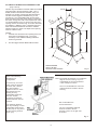
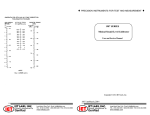
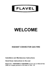
Robinson Willey D269
Handbook
Contemporary,
Charisma, Classic
(BRASS OR CHROME with
COAL EFFECT)
Desire
( STAINLESS STEEL with
PEBBLE EFFECT )
Cat I2H G20 at 20mbar For use in GB and IE.
The data plate is located at the bottom left hand side of the firebox
This handbook contains both Installer and user information and must be left with the owner.
CONTENTS
SECTION
PAGE
INSTALLATION SECTION
INTRODUCTION AND GENERAL REQUIREMENTS
TECHNICAL DATA
CONTENTS OF SCREW PACK
CONTENTS OF CERAMIC FUEL COMPONENT PACK
CONDITIONS OF INSTALLATION
SITING GENERAL
FLUES AND CHIMNEYS
Brick Chimney, 178mm diameter (7 inch)
Stone or Lined Flue and 125mm diameter (5 inch) Flue
Pre-Cast Flue
Rebated Surround Installation
Metal Fluebox 125mm diameter (5 inch) Flues
SHELF HEIGHT AND SIDE CLEARANCES
INSTALLATION OF FIRE
UNPACKING
PREPARATION OF FIRE
Spigot Restrictor
Fender Mask
Burner Tray (manual)
Burner Tray (slider)
METHODS OF INSTALLATION
Fixing by Tension Cable
Fixing Directly to Surround Face
GAS CONNECTION
Concealed Connection
TEST FOR GAS SOUNDNESS
COMMISSIONING
INSTALL FUEL EFFECT COMPONENTS
CHECK GAS PRESSURE/FIT TRIM AND ASHPAN
TEST FOR SPILLAGE
CHECK IGNITION
CHECK OPERATION OF FSD
INSTRUCT USER
SERVICING INSTRUCTIONS
REMOVE BURNER TRAY
MAIN BURNER INJECTOR
GAS TAP ASSEMBLY
PILOT ASSEMBLY
FUEL EFFECT COMPONENTS
MAIN BURNER
CONTROL KNOB
HINTS ON FAULT FINDING
1.0
2.0
3.0
4.0
5.0
5.1
5.2
3
3
4
4
5
5
5
5.2.1
5.2.2
5.2.3
5.2.4
5.3
6.0
6.1
6.2
6.2.1
6.2.2
6.2.3
6.2.4
6.3
6.3.1
6.3.2
6.4
6.4.1
6.5
7.0
7.1
7.2
7.3
7.4
7.5
8.0
9.0
9.1
9.2
9.3
9.4
9.5
9.6
9.7
10.0
5
6
7
8
9
9
9
9
9
10
10
10
11
11
11
12
12
12
13
13
14
14
14
14
15
15
15
15
15
16
16
16
16
17
11.0
11.1
12.0
13.0
13.1
13.2
13.3
14.0
14.1
14.2
14.3
14.4
15.0
15.1
18
18
19
20
20
20
20
21
22
22
23
24
24
24
USER SECTION
USER INFORMATION
SHELF HEIGHT AND SIDE CLEARANCES
CLEANING AND MAINTENANCE
OPERATING INFORMATION
MANUAL CONTROL VERSION
SLIDER CONTROL VERSION
REPLACING THE BATTERY (DESIRE)
FUEL EFFECT COMPONENTS PLACEMENT-ALL
PEBBLE LAYOUT
LIGHTING WITH TAPER-PEBBLE FIRE
COAL LAYOUT
LIGHTING WITH TAPER-COAL FIRE
SPARES AND SERVICES
PARTS REPLACEABLE BY USER
2
1.0 INTRODUCTION
NO COMPONENT OF THIS FIRE IS MANUFACTURED FROM ASBESTOS OR ASBESTOS RELATED PRODUCTS.
This appliance is an open fronted inset live fuel effect gas fire, it is suitable for use with Brick Chimneys(including lined), twin walled or
insulated Metal/Pre-fabricated Flues of 125mm minimum diameter and Flueboxes conforming to the constructional requirements of BS
715 and Pre-Cast Flue applications. It is fitted with a combined flame supervision and oxygen depletion monitoring device. The fire is for
hearth mounting only on a non-combustible hearth. If required the fire can be fitted using a 152mm (6”) rebated surround if it is to be
installed in a pre-cast flue (optional extras are required).
1.1 GENERAL INSTALLATION REQUIREMENTS
In your own interest and that of safety, it is the law that all gas appliances are installed by competent persons in accordance with the
current Gas Safety (Installation and Use) Regulations. Failure to install appliances correctly could lead to prosecution.
The installation MUST be in accordance with these installation instructions, all the relevant parts of the Local and National Building
Regulations or Building Standards (Scotland) (Consolidation) Regulations and the relevant recommendations of the current editions of
the following British Standards:
B.S. 5871 : Part 2
B.S. 5440 : Parts 1 and 2
B.S. 6891
B.S. 6461 : Parts 1 and 2
B.S. 1289 : Part 2
B.S. 715
B.S. 1251
B.S. 1289
B.S. 1289 : Part 1
Any other relevant British Standard Code of Practice and/or Local Building Regulations and in accordance with the rules in
force.
This appliance must be installed in accordance with the rules in force, and used only in a sufficiently ventilated space.
Consult instructions before installation and use of this appliance.
2.0 TECHNICAL DATA
D269 - SuperEco range of I.L.F.E. Gas Fires (Contemporary, Charisma, Classic & Desire).
The efficiency of this appliance has been measured as specified in BS 7977-1:2002 and the result is 61.5%. The
gross calorific value of the fuel has been used for this efficiency calculation. The test data from which it has
been calculated has been certified by Notified Body No. 0087. The efficiency value may be used in the UK
Government's Standard Assessment Procedure (SAP) for energy rating of dwellings.
The above exceeds the minimum requirement of 45%.
1.1
DIMENSIONS
(Contemporary, Charisma, Classic & Desire)
(Overall)
mm
Height
595
Width
500
Depth
140
Forward Projection
90 (Desire 65)
Height to top of flue aperture
504
1.2
INPUTS AND PRESSURES
Natural Gas
Maximum Heat Input
Maximum Heat Output
Efficiency Class
Supply Pressure
Setting Pressure
6.5 kW (GROSS)
22178 Btu/h
4.0 kW
13648 Btu/h
II
20.0 mbar
8.0 in wg
16.8 mbar ( ± 1 mbar)
6.5”w.g ( ± 0.4 in wg)
1.3 BURNER AND CONTROL DETAILS
Main Burner
Pilot Burner
Injector (Main Burner)
Spark Gap
Manual Control
Slider Control
Battery (Slider option)
SP988930
SP822468
SP822469
3.0mm to 5.0mm
SP822395
SP822596
9V PP3
3
3.0 CONTENTS OF SCREW PACK
Fig. 1.
The contents of the screw pack are as follows
(refer to Fig 1.): Key
Qty
Description
A
B
C
D
E
F
G
H
J
2
2
2
4
4
4
4
1
2
Fixing Cables
Cable Adaptors
Grub Screws
Cable Eyelets
Wall Plugs
Fire Fixing Screws
No 6 Self Tapping Screws
Gas Inlet Grommet
Cable Tensioning Bolts
K
2
No. 8 Self Tapping Screws
(not illustrated)
J
H
A
E
I
G
C
B
D
F
NOTE: Also included in the pack is the ‘Spacer’ required to fit the fire to some pre-cast flues - see section 5.2.2 page 6. The two
screws - item K above - may be required.
4.0 CONTENTS OF CERAMIC FUEL COMPONENT PACK
The contents of the ‘pebble’ set are as follows(see fig 2a) : -
The contents of the coal set are as follows (see to Fig 2b.): -
Key
Qty
Description
Key
Qty
Description
I
II
III
IV
V
VI
1
1
1
1
17
1
Base Ceramic Matrix
Centre Ceramic
Left Hand Side Cheek
Right Hand Side Cheek
Pebbles (see photograph)
Back brick panel
(Supplied fitted in fire)
I
II
III
IV
V
VI
VII
1
1
1
1
4
14
1
Base Ceramic Matrix
Centre Ceramic
Left Hand Side Cheek
Right Hand Side Cheek
Front Coals
Standard Coals
Back brick panel
(Supplied fitted in fire)
Fig. 2a
II
Fig. 2b
I
I
II
VI
III
IV
V
VII
V
VI
4
III
IV
5.0 CONDITIONS OF INSTALLATION
5.1
SITING GENERAL
This fire is suitable for hearth mounting only on a non-combustible hearth at least 13mm thick and measuring at least 630mm wide by
330mm deep, the periphery of which should preferably be 50mm above the floor level in order to discourage the placing of carpets or
rugs over it. It MUST NOT be fitted directly on a combustible wall. The fire should be installed so that no part of a combustible wall i.e. not
part of the fire surround but a full wall at 90o to the fire is less than 500mm from the radiant source. If this is not possible the combustible
side wall must be suitably protected.
FIREPLACE OPENING
The front opening of the fireplace must be between 406mm and 457mm wide and between 550mm and 572mm high (see Section 5.2). If
the opening is greater it must be bricked up until the opening is a maximum of 572mm high and 457mm wide, alternatively a noncombustible infill panel may be used to achieve the required dimensions.
DO NOT USE THE BACK OF A FIRE SURROUND OR MARBLE TO ACHIEVE THE ABOVE DIMENSIONS.
There must be a minimum flat surface area around the fireplace opening shown by the dotted lines in Fig. 4 to ensure a good seal
between the fireplace and the fire. This area should be sound enough to take the wall plugs and screws supplied for front fixing. Ensure
that the base of the fireplace is level with the hearth and reasonably flat to prevent the fire rocking.
Purpose built ventilation bricks or additional air vents are not normally required in the room in which the fire is fitted unless specified by
the rules in force.
IMPORTANT: When fitting any heating appliance or wallpapering a room in which one is fitted, soft wall coverings such as heat sensitive
wallpapers may become heat damaged or discoloured especially in the area above the fire. Please bear this in mind when installing or
decorating.
FIRE SURROUND:
The fire is suitable for purpose-made proprietary hearths/surrounds with temperature rating of 150oC.
5.2
FLUES AND CHIMNEYS
5.2.1 SITE REQUIREMENTS FOR 228mm BY 228mm (9in BY 9in) BRICK CHIMNEY/178mm (7in)
STONE OR LINED CHIMNEY AND 125MM (5in) DIAMETER FLUE
The minimum dimensions for the fireplace opening for a brick chimney are as shown in Fig. 3. It will not normally be necessary to remove
any chair brick provided the minimum depth is obtained. A chimney previously used to burn solid fuel must be swept prior to installation.
The chimney must be inspected to ensure that:
(a)
It serves only one fireplace.
(b)
It is properly sealed so that combustion products do not escape from the flue into the room.
(c)
It is not blocked by paper, rubble etc.
(d)
Any restriction such as damper, register plate, etc. must be removed or secured in the fully open position.
(e)
Any underdraught ventilation or additional air supply
entering the fireplace or on the hearth must be
sealed off.
(f)
It must have at least 3 metre effective flue height.
(g)
It must have a positive updraught.
IN
505 mm M
CHECK THE FLUE FOR GOOD DRAUGHT
Apply a lighted paper or smoke match to the top of the
opening in the fireplace. Observe if there is a definite flow
into the chimney and if so proceed with fitting the fire.
If no flow is indicated, warm the chimney for several minutes
and then re-check. If downdraught is observed a suitable
terminal must be fitted and the chimney re-checked.
If persistent no-flow or downdraught condition is observed
550 mm MIN
572 mm MAX
610 mm MIN
DO NOT FIT THE FIRE, SEEK EXPERT ADVICE.
165 mm
MIN
MIN
406 mm MAX
m
457 m
5
Fig. 3
5.2.2 PRE-CAST FLUE OF MINIMUM SIZE (Fig. 4)
PRE-CAST FLUE INSTALLATION
This fire can be installed into a properly constructed pre-cast
flue conforming to B.S. 1289 : 1975 or B.S. 1289 : Part 1 : 1986
or B.S. 1289 : Part 2 : 1989 of at least 3 metres effective height
and having flueways of at least 198mm by 67mm or equivalent
cross-sectional area with no dimension less than 63mm. The
fireplace opening width must be between a maximum 457mm
and a minimum 406mm. The fireplace opening height must be
between a maximum of 572mm and a minimum 550mm and a
depth of at least 120mm above the hearth level.
Fig. 4
NOTES:
1. The minimum dimensions for the flat area around the
opening are 610 mm high x 505mm wide.
2. The flue spigot restrictor MUST NOT be fitted.
Ensure that any mortar fangs between the blocks do not
protrude into the flueways and if raking blocks are used they are
fitted according to the manufacturers instructions and mortar is
not allowed to drop down and accumulate in the raked portions.
CHECK THE FLUE FOR GOOD DRAUGHT AS DETAILED IN
SECTION 5.2.1.
15
M 0
IN
Pre-cast Flue Depths
This fire is designed to fit into a Pre-cast Flue with a depth of
150mm (see fig 4). In order to achieve that dimension the fitting
of a marble back and (or) the spacer might be required. The
spacer is supplied with the fire, to re-order the spacer please
quote part number Sp988806.
Fitting the spacer
If the fire is to be installed using the cable fixing method the spacer should be fitted to the fire in the following manner.
This must be carried out in conjunction with section 6.3.1.
Cable fix:This method requires the Spacer to be fitted to the rear of the fire before installing.
1. Hook the brackets at the bottom of the spacer under the sides flanges of the firebox of the fire.
2. Swing the top of the spacer against the top of the fire and hold in position, fix with two No. 8 x 1/2” self tapping screws, into the
captive nuts fitted in the spacer.
Screw fix:If the fire is to be screw fixed to the face of the opening, then the spacer is fitted to the face of the opening first (not the fire).
1.Remove, and retain, the captive nuts from the top of the spacer - observe how they are fitted.
2. Locate the spacer centrally in front of the opening and mark through the top two holes.
3. Remove the spacer and drill the marked positions to accept wallplugs.
4. Fit the wallplugs and fix the spacer using wood screws. Re-fit the captive nuts in the top of the spacer.
5. Engage the side flanges of the fire into the brackets on the bottom of the spacer, and temporarily fit the top two fixing screws.
6. Push the fire back and maintain pressure against it’s ‘wall’ seals, whilst marking through the bottom fixing holes.
7. Drill and plug the bottom holes, and fit the fire.
Marble
Marble
Spacer
130
mm
110
mm
6
5.2.3 REBATED SURROUND INSTALLATION
When fitting the fire to a pre-cast flue it is possible to use a 152mm deep rebated surround. Two optional extras are required as follows: Part Number
Closure Plate
Spigot
989571
989568
Fit the closure plate to the wall ensuring that a good seal is made between the plate and the wall. The plate has been designed to sit on the
floor behind the rebated surround or hearth. This will position the spigot opening at the correct height for the spigot when using a 50mm
high hearth. If your hearth is of a different height reposition accordingly.
If using a concealed gas connection ensure it is installed before fitting the closure plate. Knock-outs are provided for gas piping.
Fit the spigot to the rear of the fire using the four screws provided in the screw pack. Refer to Figures 5 and 6. Proceed as follows: Position the spigot on the rear of the fire.
Screw from inside the canopy into the spigot. It is easiest to start each screw before tightening fully.
DO NOT FIT THE RESTRICTOR
Fig 6.
Fig 5.
50mm MINIMUM (2in)
4 SPIGOT SCREWS
500.0
244.0
46.5
Fig 7.
660.0
560.5
78.0
GAS SUPPLY PIPE KNOCK OUTS
100.0
=
=
7
5.2.4 METAL FLUE BOX/125mm DIAMETER FLUES
(Figs. 8 and 9)
2.
45
98 UE E
FL NTR
CE
31
7
7
610
NOTES:
1. If the flat area around the front opening of the box
is less than as specified in Fig. 3, it may be
necessary to use additional sealing material to
achieve a good seal.
125 I/D
560
This fire may be installed in a double walled or insulated
metal box built to the requirements of B.S. 715 e.g.
Selkirk, Product Code Number 0404905, using our
fixing kit G.C. Number 159 634 Part Number 992137.
The box must be lagged as detailed in Fig. 9 and
mounted on a non-combustible plinth at least 25mm
thick. Ensure that the base of the opening is level with
the hearth. A larger box built to the requirements of B.S.
715 and insulated as in Fig. 9 may be used. The front
opening must be as shown in Fig. 8. The flue should be
twin walled e.g. Selkirk IL flues, or insulated type of at
least 125mm internal diameter and with a minimum
effective height of 3 metres. The depth of the opening
must be at least 317mm.
The flue spigot restrictor MUST NOT be fitted.
40
7
33
0
FREESTANDING
GAS FLUE BOX
SELKIRK CODE 0404905
Refer to the following
illustrations for
configuration.
Fig. 8
Note: The plaster board does not overlap the
edge of the fire housing. Any noncombustible fire surround material
used overlaps as shown.
Cover the top, rear and
sides of the fire housing
as shown with 100mm
(4in) loft insulation
material as shown. If the
gap between the fire
housing and any
combustible material is
less than 100mm,
squeeze the insulation
material between the two
surfaces.
The non-combustible fire surround
material must be sealed to the fire
housing.
Non-combustible fire
surround material
The minimum distance
from any studding or other
combustible material and
the flue pipe or any part of
the fire housing must be
25mm (1in).
The non-combustible material
must be sealed to the fire
housing to form an air tight seal
all around.
Fig. 9
8
5.3 SHELF HEIGHT AND SIDE CLEARANCES
The fire may be fitted beneath a shelf. See ‘User section’ (PAGE 18).
6.0 INSTALLATION OF FIRE
6.1
UNPACKING
The fire is packed with the rear brick board already fitted in position. When unpacking refer to the check list to ensure that all of the
components are present and undamaged. Remove the top fitment from the carton - this contains accessories for the ‘Pebble version’. .
Remove the spacer . Lift the carton surround clear of the fire. Remove the Fender & Ashpan (not ‘Pebble version’) and coal packs. The
trim is held in place at the bottom by magnets and the top of the trim is hooked over the top of the firebox, to remove it first pull the trim
away from the magnets then lift it upwards. Lift the fire clear of the bottom fitment of the carton.
Pack Contents: (1)
(2)
(3)
(4)
1
1
1
1
Fire Assembly (Complete with trim)
Spacer
Ceramic fuel components pack
a) Coal effect
Fender/Ashpan Pack, also contains:i) Screw Pack
ii) Owners Handbook
iii) Spigot restrictor
iv) Battery- PP3 in blister pack (Slider control only)
b) Pebble effect
Items i) to iv) above are located in the top packing fitment.
6.2
PREPARATION OF FIRE
6.2.1 SPIGOT RESTRICTOR
The spigot restrictor is supplied in the fender pack and should be fitted only in the case of installation to a brick chimney, 178mm
diameter stone/lined flue of at least 3 metres effective height, with good draught. DO NOT fit the spigot restrictor if installation is to
a PRE-CAST FLUE or a METAL FLUE BOX / 5 INCH FLUE.
Fit the restrictor, the formed section facing into the fire and the flat back against the firebox, with two No. 8 self tapping screws
supplied in the screw pack (see Fig 10).
2 SPIGOT
RESTRICTOR
FIXING SCREWS
Fig 10.
9
6.2.2
Remove the fender mask by removing the two screws.
Refer to Fig 11a.
Fig 11a.
6.2.3
For the ‘Manual’ version, remove the burner tray by
removing the two screws.
Refer to Fig 11b.
Fig 11b.
6.2.4
For ‘Slider’ version, release the ‘link arm’ at the
lower R.H. Side. Set control to ‘Medium setting’ and
remove connecting screw. Allow ‘link arm’ to rest on
support plate.
Refer to ‘enhanced view’ of Fig 12.
Then remove the burner tray by removing the two
screws, taking care not to damage the ‘link arm’.
Refer to Fig 12.
Connecting screw
link arm
Support plate
Please ensure the control is at the ‘Medium’ setting (marked ’II’) for ease of re-assembly.
10
Fig 12.
6.3
METHOD OF INSTALLATION
There are two methods for securing the fire to the wall which are:
(a)
Fixing by tension cable.
(b)
Screwing the fire directly to the wall.
It is recommended, where drilling holes in the front face of the fireplace surround is unacceptable or otherwise risky e.g. a marble
surround, that fixing by tension cable is employed.
IMPORTANT NOTES
(a) If the surface of the fireplace is uneven it is necessary to prepare the surface so that a positive seal can be achieved
between the fire and the wall.
(b) If the fire is to be connected using a concealed gas connection then it is necessary to prepare the pipework prior to fitting the
fire to the wall. Refer to Section 6.4.1. (Concealed Connection).
6.3.1 FIXING BY TENSION CABLE
FIT MOUNTING EYE SCREWS
Mark the position for eye screws in the back of the opening according to the dimensions in Fig. 13. Drill the four 6mm holes and plug the
holes with the wall plugs. Fix the eye screws to the holes.
FIXING THE CABLE
First remove the burner tray (see Section 6.2). Prise the tabs up on each side of the firebox using a screw driver (refer to Fig 14.). Fit the
cable tensioning bolts into the fire from the front, i.e. Hexagon head inside the fire. Insert the free end of each cable through the
respective hole in the firebox and then through the eye screws (refer to Fig. 13). Thread the free ends of the cable through the holes in
the tensioning bolts from the rear. Insert the fire into the opening so that the seal on the back of the fire is compressed against the face of
the fireplace/surround. Any visible gaps indicate a deviation from flatness of the surround face which MUST be corrected. Pull the cable
taut each side of the fire and insert the cable adaptors over the ends of the cable (Fig. 13). While keeping the cable taut slide the adaptor
against the tensioning bolt and tighten the grub screw to lock the cable. Using a spanner unscrew each tensioning bolt by about 20mm to
tension the cable. Prevent the cable adaptors from rotating while unscrewing the tensioning bolts. DO NOT cut the ends of the cables,
but coil them up instead as shown in Fig 15 to facilitate refitting of the fire after servicing.
24
0
CE
RE
NT
S
C
LA
EP
FIR
OF
K
C
BA
E
EYE
SCREWS
7 0 mm
75 mm
375
3
Fig 14.
R
OO
FL
CABLE
TENSIONER BOLT
GRUB SCREW
CABLE
ADAPTOR
Fig 13.
Fig 15.
6.3.2 FIXING DIRECTLY TO SURROUND FACE
Mark the four positions of the fixing holes, two on the front face of the fireplace surround and two in the floor, using the fire as a template.
Drill 6mm holes and plug the holes with the wall plugs supplied. Insert the fire into the opening in the fireplace until the seal on the back of
the fire is compressed against the surround face at every point. Note that any visible gaps between the surround face and the seal
indicate a deviation from flatness on the surround face and MUST be rectified. Screw the fire to the wall.
11
6.4
GAS CONNECTION
NOTE: The appliance must be connected to gas with rigid or
semi-rigid tubing, from either the right or left hand side, or by
concealed connection (see below). The supply pipe to the fire
should be installed so that it is easy to remove the fire from the
opening during servicing. An isolation inlet elbow is fitted to the
burner assembly for isolation of the fire for servicing at a later
date.
Fig 16.
If a concealed connection from within the fireplace is required
then, before the appliance is fitted into the fireplace, it will be
necessary to extend the supply line so that it will project through
the sealed opening situated at the back of the firebox to the
appliance inlet elbow.
Manipulating the fire onto/off the gas supply during installation
or servicing is best carried out with the burner assembly
removed, after removal of fender mask (see section 9.1)
6.4.1. CONCEALED CONNECTION
Remove the isolation elbow from the burner assembly.( Fig 16).
Knock out at the required position using a hammer and
screwdriver to gently but firmly knock out the hole. Refer to
Fig17.
Push in the hole the large grommet provided in the screw
Pack. If necessary the grommet can be softened by placing it on
top of a kettle whilst it is boiling until supple.
Fig 17.
Cut a cross in the centre of the grommet to suit the size of supply
pipe. Fig 18.
Push the supply pipe through the hole just created and connect
the isolation elbow removed from the burner assembly. Refer to
Fig 19.
The end position is shown below. The pipe run from the supply
line up to the rear opening in the firebox must be kept clear of the
area which will be taken by the box when it is installed.
Manual Control inlet position
30mm
Fig 18.
FACE OF SURROUND
48mm
Slider Control inlet position
36mm
Fig 19.
FACE OF SURROUND
73mm
6.5
6.4.1. Refit Burner and Fender Mask
This is the reverse of the procedures detailed in Sections
6.2.2. to 6.2.4. (See page 10 ), but for the ‘Slider’ version
the battery must first be fitted.
TEST FOR GAS SOUNDNESS
The gas installation, including meter, should be
inspected and tested for gas soundness and purged.
Refer to B.S. 6891 when performing gas soundness
testing.
12
7.0 COMMISSIONING
7.1 INSTALL FUEL EFFECT COMPONENTS
The base ceramic matrix, side cheeks and fuel effect components are illustrated in Fig 2. The fire is supplied with the rear brick
effect panel already fitted as illustrated in Fig 11.
Unpack the pack containing the ceramic fuel effect components and check that these are undamaged and complete.
Install the fuel effect components as detailed on pages 21 and 22/23 of the Users section of this booklet.
DO NOT INSTALL THE FIRE WITH BROKEN OR MISSING CERAMIC FUEL COMPONENTS. USE ONLY THE CERAMIC FUEL
COMPONENTS SUPPLIED WITH THE FIRE.
Handling Ceramic Fuel Components
This product uses fuel effect pieces containing Refractory Ceramic Fibre (RCF), which are man-made vitreous silicate fibres.
Excessive exposure to these materials may cause temporary irritation to eyes, skin and respiratory tract, consequently, it makes sense
to take care when handling these articles to ensure that the release of dust is kept to a minimum.
To ensure that the release of fibres from these RCF articles is kept to a minimum, during installation and servicing we recommend
cleaning should be carried out in a well-ventilated area or in the open air, by gently brushing with the pieces held away from your
face so that you avoid inhaling the dust. We do not recommend the use of a normal domestic vacuum cleaner, which may blow
dust back into the air. If a vacuum cleaner is recommended for use by your organisation, you must use a HEPA filtered vacuum to
remove any dust and soot accumulated in and around the fire before and after working on the fire. When replacing these articles
we recommend that the replaced items are not broken up, but are sealed within heavy duty polythene bags, clearly labelled as
RCF waste. This is not classified as "hazardous waste" and may be disposed of at a tipping site licensed for the disposal of
industrial waste. Protective clothing is not required when handling the articles, but we recommend you follow the normal hygiene
rules of not smoking, eating or drinking in the work area and always wash your hands before eating or drinking.
Advise the customer that they should read their Users instructions before operating the fire and always follow the advice in the Section
headed "Cleaning and Simple Maintenance".
7.2 CHECK GAS PRESSURE
Remove the pressure test point screw located on the injector feed at the centre of on the fire.
Connect a pressure gauge, depress the control knob and rotate to the PILOT/IGNITION position until the piezo sparks. Keep the knob
depressed after the pilot has lit to activate the FSD and then rotate the knob to the HIGH position.
Check that the gas pressure is as specified in Section 2.0 Technical Data. Turn off the fire and disconnect the pressure gauge.
Replace the test point screw, relight the fire and test for gas soundness around the sealing screw using a suitable leak detection fluid.
Fitting the outer trim and Fender.
1.
a) Coal effect
Fit the trim to the fire by hooking it over the top of the
firebox. The bottom of the trim is held in place with a
magnet, each side. Push the bottom of the trim at each
side onto the magnet.
b) Pebble effect
The outer trim and fender are a one piece assembly. Fit
by hooking over the top of the firebox, and swing down
to engage the bottom on the magnets at each side.
NOTE: If the magnet on either side came away with the
trim on removal, transfer it back to the “bracket”
on the fire before re-fitting the trim.
Trim magnet attached to bracket
2.
Coal effect only
Locate the fender centrally in front of the fire and
position the ash pan cover.
13
7.3 TEST FOR SPILLAGE
A test for spillage must be made before the installed fire is left with the user. This is carried out in the following manner. Light the fire and
leave at HIGH rate. Close all the doors and windows in the room and after the fire has been alight for five minutes insert a lighted smoke
match into the notch in the canopy in a horizontal direction with the tip 50 mm inside the canopy (See Fig. 20). Hold the match in a metal
tube. If all of the smoke is drawn into the fire the installation is satisfactory. If in doubt, repeat the test after a further ten minutes.
If there is a fan or a fan operated appliance in a connecting room then the spillage test must be repeated with the fan running and all
inter-connecting doors between the fan and the fire left open. If the fan and the fire are in the same room, close all windows and doors
connected to the room. Switch on the fan and repeat the spillage test.
If spillage is detected, inspect the sealing of the fire to the surround / hearth. If this is satisfactory proceed as follows:
If a spigot restrictor was fitted, turn the fire off and remove the spigot restrictor. Re-light the fire and repeat the above spillage test. If
there is still evidence of spillage then there may be a fault with the chimney or insufficient air in the room. If the cause of the spillage
cannot be corrected DISCONNECT THE FIRE AND SEEK EXPERT ADVICE.
Fig 20.
SMOKE MATCH IN TUBE
50 mm
Fig. 21.
7.4 CHECK IGNITION
Check that ignition of the pilot and the cross lighting to the main burner is
satisfactory.
3.0
-5
.0
m
m
NB. The spark gap between the electrode and thermocouple tip should
be between 3.0 and 5.0mm (See Fig 21.).
7.5 CHECK OPERATION OF FSD
Leave the fire running on HIGH rate for 5 minutes and then turn off the
gas at the service cock. After 3 minutes turn the service cock on again. If
the gas has stopped flowing the FSD has operated satisfactorily.
NOTE: You may hear the FSD valve close within the 3 minute period but
always check that the gas has stopped flowing.
14
8.0 INSTRUCT USER
Refer to Users Instructions
Make sure the user understands the following:
(a) How to light and operate the fire.
(b) The fire can be lit with a match or taper in the event of failure of the spark ignition.
(c) Demonstrate the removal and replacement of the coals, drawing attention to keeping the FOUR FRONT coals separate.
Advise on the need to clean these regularly.
(d) Advise that for safe and efficient operation, the fire should be serviced annually by aGas Safe registered Engineer.
(e) Explain to the user the functioning of the combined flame supervision and atmosphere monitoring device as detailed in
Section 9.4. Stress that if this device repeatedly shuts off the fire, the fault must be rectified immediately by a competent
person.
(f) When the fire is first lit a slight smell and light smoke may be noticed but this will clear away with a few hours of use on HIGH.
(g) Advise the user to carefully clean the base of the fire with a vacuum cleaner regularly.
Hand over the Instructions Handbook
9.0 SERVICING INSTRUCTIONS
IMPORTANT NOTES
1.
Turn off the gas supply to the fire before starting any servicing.
2.
Always test for gas soundness after servicing or exchanging any component.
3.
Remove the fire from the surround and inspect the catchment space for build up of debris on every service visit.
4.
Check the fire for clearance of products on every service visit.
5.
Remove any lint from the top of the main burner and from around the aeration hole of the pilot and main burner.
9.1
1.
2.
3.
4.
5.
REMOVE BURNER TRAY
Remove the fender and ash-pan cover.
Remove the loose coals and coal bed.
Isolate and disconnect the gas supply at the inlet to the fire.
Remove the two screws securing the fender mask to the firebox and remove the fender mask (see 6.2.2).
Remove the two screws securing the burner tray to the firebox and slide out the burner tray (see 6.2.3 and 6.2.4 for ‘manual’
and ‘slider’ controls respectively).
WARNING: If you turn the tray upside down, take care not to damage the pilot burner head.
9.2 BURNER INJECTOR
1.
Remove the burner tray (Section 9.1 above).
2.
Undo the union nut at the gas valve end.
3.
Undo the two screws securing the injector bracket and aeration control plate to the burner manifold and remove the pipe
assembly.
4.
Unscrew the injector from its holder, and remove the injector.
5.
Replace with the new injector.
6.
Re-assemble in the reverse manner.
9.3
1.
2.
3.
4.
5.
6.
7.
8.
GAS VALVE / FSD ASSEMBLY
Remove burner tray (Section 9.1 above).
Turn the tray upside down, taking care not to damage the pilot burner head.
Undo the gas connections to the gas valve.
Release the thermocouple nut and ease out the probe, and remove the battery on the slider version (to avoid shorting when
the microswitch leads are removed).
Disconnect the ignition lead from the spark generator (manual) or the leads from the control microswitch (slider).
Remove the two screws securing the gas valve to its bracket and remove the gas valve.
Replace with the new gas valve/fsd assembly.
Re-assemble in the reverse manner.
15
9.4
PILOT ASSEMBLY
The pilot is an atmosphere sensing device and must be replaced as a complete unit. Repair must not be undertaken.
NOTE: If the fire keeps going out or exhibits signs of nuisance shut off, check the operation of the pilot as follows:(a)
(b)
(c)
(d)
(e)
(f )
Check the pilot lint trap for blockage. Remove any lint present.
Inspect the pilot flame, if suspect check the gas supply. Inspect the filter in the pilot outlet of the tap.
Clear blockage if necessary. If flame is still suspect replace pilot assembly.
Check the thermocouple. If faulty replace the pilot assembly.
Check the magnet unit in the gas valve. If faulty replace the valve.
Check the ventilation in the room. Vitiation may be due to lack of sufficient air supply.
Check for satisfactory clearance of combustion products. Vitiation may be due to spillage of combustion products into the room.
1.
2.
3.
4.
5.
6.
7.
Remove burner tray (Section 9.1 above).
Release the pilot supply pipe at the pilot end and ease out the pipe.
Undo the thermocouple nut at the gas valve end and ease out the thermocouple.
Pull off the spark lead at the pilot end.
Remove the two screws securing the pilot assembly (and insulation pad) to its bracket.
Fit the new pilot assembly.
Re-assemble in the reverse manner.
9.5 FUEL EFFECT COMPONENTS
The loose fuels (see note below), base ceramic matrix, centre ceramic and the side cheeks simply lift out - see section 14.
NOTE: on removal of loose coals, keep separate the four front coals (see fig 26b) for correct replacement.
To replace the rear brick panel proceed as follows:
1.
Remove burner tray (Section 9.1)
2.
Loosen the screws securing the lower support and slide out the brick effect panel.
3.
Replace with a new one, and re-tighten screws.
9.6 MAIN BURNER
1.
2.
3.
4.
5.
6.
7.
Remove burner tray (Section 9.1)
Undo the two screws securing the pilot assembly to the burner.
Undo the two screws securing the injector to the burner manifold.
Turn the tray upside down.
Undo the two screws securing the burner to the tray and remove the burner.
Transfer the injector box mounting plate to the new burner.
Fit the new burner and re-assemble in the reverse manner remembering to refit the pilot (including insulation pad)..
9.7 CONTROL KNOB
Manual version
1.
Remove the ash-pan cover.
2.
Pull the control knob from the spindle.
3.
Replace with a new knob ensuring that the `D’ flat in the hole lines up with the flat on the spindle.
Slider version.
1.
The lever operating system has a ‘Push Fit’ sleeve, which can be pulled off to remove.
2.
Fit replacement by pushing it onto lever.
16
10.0 HINTS ON FAULT FINDING
The following are possible fault conditions. Check the items mentioned and repair or replace parts as necessary. The list is not
exhaustive but a fair outline of possible faults.
1.
No Spark
(a)
(b)
(c)
2.
Spark but the pilot does not light.
(a)
(b)
(c)
(d)
3.
(b)
Check for linting of the pilot lint trap filter(Steel gauze fitted around the body of the pilot burner) and the aeration hole
under the filter.
Pilot starvation due to partial blockage. Clean the pilot gas supply line. See also 2(c) and 2(d) above.
Nuisance shut off.
(a)
(b)
(c)
(d)
(e)
(f)
5.
Verify availability of gas at the pilot burner, if possible, light with a match.
If gas is available, proceed as in 1 above.
If gas is not available, check the pilot burner and supply pipe for blockage.
Ensure gas is available at the pilot port of gas tap, if not replace the tap.
Pilot lights but goes out on heat setting.
(a)
4.
Check spark by manually operating the spark generator.
Check the spark gap and electrode alignment (see Fig 21). The electrode, thermocouple probe and horizontal arm of the
pilot burner should be in a straight line.
Inspect the spark lead, ensure firm contact at the ends and that there is no shorting out of spark at either end.
Inspect the pilot flame.
Check the thermocouple. If faulty replace the pilot assembly.
Check the magnet unit in the gas tap. If faulty replace the tap.
Check the ventilation into the room. Vitiation may be due to the lack of sufficient air supply.
Check for satisfactory clearance of combustion products. Vitiation may be due to spillage of combustion products into
the room.
Remove spigot restrictor if fitted.
Main burner popping.
Remove the loose fuel effect components. Light the fire and inspect the burner for cracks and leakage. Replace the burner if
necessary.
6.
Poor flame picture.
(a)
(b)
(c)
(d)
7.
Remove the burner assembly. Check the alignment of the burner ports with the holes in the base ceramic matrix. Ensure
the ports are clear.
Re-assemble correctly and check the flame picture.
Check the gas rate.
Check fuel effect layout is correct to these instructions.
Sooting.
Proceed as in 6 above.
8.
Spillage.
(a)
(b)
(c)
(d)
Check the seal of the fire to the wall/surround.
Inspect the chimney.
Remove the spigot restrictor if fitted.
Check the fuel effect arrangement.
17
USER SECTION
11.0 USER INFORMATION
This fire must be installed and serviced regularly in accordance with the Gas Safety (Installation and Use) Regulations and the
rules in force by a competent person e.g. a Gas Safe registered Engineer. Where solid fuel has been used the chimney must
be swept before installation. This fire must be installed in accordance with the installation instructions.
It is recommended that at least once a year the appliance should be removed to check the catchment space and the chimney
for debris. The fire should be checked annually to ensure continued clearance of combustion products and that there is no
excessive build up of soot.
WARNING: This fire has a naked flame. Also certain parts, especially the canopy, will be hot when in use. A fireguard
conforming to B.S. 8423 (Fireguards for heating appliances for domestic use) should be used for the protection of children, the
elderly or the infirm. Such a guard is also recommended for pet animals.
After the fire has been installed you may wish to fix a shelf of combustible material above. This is quite acceptable provided the
dimensions comply with the diagram shown below. The specification of materials used in ‘Surrounds’, other than marble and
wood, must be checked to confirm satisfactory performance.
Clothes etc. must not be draped over or near the fire.
When the fire is first used it may give off some slight smoke and smell but these will soon clear after a few hours of use at the
HIGH setting, preferably with windows open.
Do not burn paper or any rubbish in the fire.
IMPORTANT: When considering fitting any heating appliance or wallpapering a room in which one is fitted, if
blown vinyl or other heat sensitive wallpapers are used in the vicinity of the heat source, then they may become heat
damaged or discoloured especially just above the fire.
It is important for safe operation and to maintain efficiency that the fire is not operated with damaged or broken coals.
IMPORTANT NOTE: Under no circumstances should extra coals be used together with the existing coals.
ONLY THE CORRECT COALS SHOULD BE USED.
If purpose built ventilation is provided for the fire, it should be checked periodically to ensure that it is free from obstruction.
If you notice that the appliance has a floppy yellow pilot flame and/or there is difficulty in lighting the appliance then the lint filter
may need cleaning. Cleaning should be carried out by vacuuming the dust and lint from the filter. If vacuuming alone is not
successful in curing the ignition problem then a Gas Safe registered Engineer must be called to investigate the problem.
Access to the lint filter requires removal of the trim, as detailed in section 13.3 on page 20.
11.1 SHELF HEIGHT AND SIDE CLEARANCES
The fire may be fitted beneath a shelf.
depth 200mm
150mm
COMBUSTIBLE SHELF
A shelf may be fitted above the heater provided that it complies with
the dimensions shown in the diagram.
No combustible shelf may be fitted below the minimum of 150mm.
The minimum clearance to combustible sides must comply with the
dimensions in the diagram.
A minimum clearance to adjacent combustible walls, of 500mm,
is required from the side of the fire.
200mm
250mm
depth 250mm
depth 150mm
Top of Fire
18
100mm
MIN
200mm
MIN
side of fire
SIDE CLEARANCES:
A clearance of at least 25mm must be left on either side of the fire to
facilitate removal of the outer case during servicing.
MAX
100mm
NON-COMBUSTIBLE SHELF
The underside of a non-combustible shelf not more than 75mm deep
must be at least 25mm above the top of the fire. This clearance is
necessary for outer case removal. For deeper shelves, allow 13mm in
shelf height for every 25mm increase in depth.
MAX
200mm
COMBUSTIBLE SHELF
CLEARANCES
COMBUSTIBLE SIDES
CLEARANCES
12 CLEANING AND SIMPLE MAINTENANCE
All cleaning should be carried out when the fire is cold.
Generally the fire will only need dusting. Any painted surface or metal part should be cleaned with a damp cloth only. Never use any
abrasive materials or metal polish on painted surfaces or metal parts.
FUEL EFFECT COMPONENTS
This product uses fuel effect pieces containing Refractory Ceramic Fibre (RCF), which are man-made vitreous silicate fibres.
Excessive exposure to these materials may cause temporary irritation to eyes, skin and respiratory tract, consequently, it makes
sense to take care when handling these articles to ensure that the release of dust is kept to a minimum.
Should any soot accumulation become excessive, the fuel effect pieces should be removed from the fire for cleaning. Cleaning
should be carried out in a well-ventilated area or in the open air, by gently brushing with the pieces held away from your face so that
you avoid inhaling the dust. We do not recommend the use of a normal domestic vacuum cleaner which may blow dust back into the
air.
If you need to remove the base ceramic matrix to dust away larger particles then it is necessary that you first remove the centre
ceramic and the side cheeks ( see pages 21 to 24). For the Desire remove the whole trim (see section 13.3 on page 20).
As you lift out the base ceramic matrix take care that you do not damage it against the pilot burner and also take precautions that
particles do not fall on your carpet etc.
Remove any deposits on the burner with a soft brush. Periodically vacuum away any loose particles that have fallen on the hearth
or into the base of the fire. For the Desire remove the whole trim (see section 13.3 on page 20).
CONTEMPORARY
CHARISMA
CLASSIC
The SuperEco range consists of the Contemporary,
Charisma and Classic models as illustrated .
Each model is available with a Brass or Chrome finish.
The operating system may be either by ‘manual control’ or
‘slider control’, as detailed on the previous page.
In addition is the ‘Slider only option’ Desire, in stainless steel
finish, with Pebbles.
DESIRE
19
13.0 OPERATING INFORMATION
WARNING: If the flames are found to be extinguished and the control is not in
the OFF position, the control should be returned to the OFF position and no
attempt should be made to light the gas until at least 3 minutes have elapsed.
WARNING: If you want to relight a hot fire wait 3 minutes before doing so.
NOTE: When you turn a hot fire off there may be some popping noise for a short
period. This should not cause alarm.
13.1 MANUAL CONTROL VERSION (NOT DESIRE)
LIGHT THE FIRE
The control knob has the markings OFF, PILOT, HIGH and LOW.
The control knob is located behind the fender ash-pan door. Depress the control
knob and rotate to the PILOT position until the piezo sparks. Refer to Fig 30b for
viewing of the pilot when lit. If the pilot did not light return the control knob to the OFF
position and try again. Once the pilot is lit keep the control knob fully pushed in for a
further 10 seconds before releasing.
If the pilot did not light or failed to remain alight, repeat the lighting procedure.
When the pilot is established, Turn the control knob to the HIGH position. Your fire is
now operating on full heat input. You may now turn the control knob to any of the
positions, HIGH, LOW or in between.
TO TURN OFF
To turn OFF, turn the control knob to the OFF position.
13.2 SLIDER CONTROL VERSION (ALL)
LIGHT THE FIRE
The control knob is illustrated, and has ‘arrest’ positions at the
markings
/PILOT (ignition), ‘I’(low), ‘II’(medium), ‘III’(high) and
‘OFF’,
The control knob is located on the right side of the fire. Fully
depress the control to the /PILOT position until the ignition
starts. Keep the control knob fully pushed down for a further 10
seconds before releasing. The pilot should remain lit and the
control knob will spring back to the ‘I’ position. Refer to Fig 29a for
viewing of the pilot when lit.
If the pilot did not light or failed to remain alight, repeat the lighting
procedure.
When the pilot is established, slide the control knob to the ‘III’
position. Your fire is now operating on full heat input. You may
now slide the control knob to another position ‘II’(Medium)’ or
‘I’(Low) as required.
II (medium)
TO TURN OFF
To turn OFF slide the control knob to the OFF position.
13.3 Replacing the battery (consumable items are not
guaranteed).
The slider control incorporates battery ignition, in the event of the
loss of power to the spark generator please replace the battery
with a standard 9v PP3 (6LR61). The battery is situated on the left
hand side of the fire, removal of the fender and ash pan cover will
expose the battery box, else for the Desire remove the whole trim
(see below). Lift the ‘clip’ holding the battery, and slide it out toward the centre of the fire - until clear of the holder. Then
withdraw forward to enable the battery connector to be removed.
Fit new battery to connector and re-fit battery under the ‘clip’.
Desire
Remove the trim assembly. Pull lower sides off retaining magnets
and lift to unhook top. Place carefully to one side. After changing
battery, replace the trim assembly by hooking over top of fire back
and lowering bottom of sides onto retaining magnets.
Pilot lint filter
Battery retaining ‘clip’
- lift to release battery.
20
14.0 INSTALLATION OF FUEL EFFECT COMPONENTS
The Fuel Effect pack contents are illustrated in Figs 2a & 2b.
The fire is supplied with the rear brick effect panel already
fitted.
This procedure is the same for both pebble and coal
versions (coal illustrated).
Unpack the Fuel Effect components and check that these are
undamaged.
DO NOT INSTALL THE FIRE WITH BROKEN OR MISSING
FUEL EFFECT COMPONENTS.
USE ONLY THE FUEL EFFECT COMPONENTS SUPPLIED
WITH THE FIRE.
The underside of the base ceramic matrix has grooves
matching the raised ports of the burner top. Fit the
matrix by placing it onto the burner. Take care to avoid
damage as you insert it past the pilot burner (Refer to
Fig 22.). Ensure that it is correctly located in the burner
tray by sliding it sideways and front to back.
Fig 22
Insert the side cheeks by sliding them down the side of
the matrix until they touch the rear brick effect panel.
(Refer to Fig 23.)
Fig 23
Lower the centre ceramic into position as shown in
Fig 24. The front edge of the centre ceramic must be
flush with the back edge of the of the sides of the base
ceramic matrix.
Fig 24
Pivot the centre coal backwards until the top back edge
of the centre coal touches the back brick( Fig 25.).
Fig 25
21
14.1 PEBBLE LAYOUT
O
O
O
G
H
Position 3 pebbles (O) on each of the platforms on the
centre coal.
Arrange pebbles (G), (H), and (A) along the front of the
base ceramic matrix as shown in fig 26a.
A
Fig 26a
I
K
O
O
O
L
J
H
G
A
Support pebbles (I) and (K) on the (O) pebbles.
Locate (J) and (L) on either side of the fuel bed (See fig
27a).
Fig 27a
F
D
N
M
C
E
B
J
Position pebbles (B) and (E), then locate (C) centrally
on the bed.
Locate pebble (M) and (N) at the sides, supported
between (J) & (O) and (L) & (O) respectively.
G
H
L
A
Finally position pebbles (D) & (F) as shown in fig 28a.
Fig 28a
14.2 LIGHTING WITH A TAPER
In the unlikely event of failure of the ignition spark the fire can
be lit with a taper or a long spill.
Remove the trim assembly. Pull lower sides off retaining
magnets and lift to unhook top. Place carefully to one side.
You should be able to see the pilot burner just below the base
ceramic matrix, to the left of centre.
Light your taper and apply it to the pilot burner. Depress the
control knob to the PILOT position.
The pilot, and main burner at low, lights and you should keep
the knob depressed for 10 seconds before releasing. The fire
should remain alight.
Before setting the fire to full heat input,replace the trim
assembly by hooking over top of fire back and lowering bottom
of sides onto retaining magnets.
APPLY TAPER HERE
22
14.3 COAL LAYOUT
Position the four separately packed coals in the
corresponding indentations on the front edge of
the base ceramic matrix. See fig. 26b.
NOTE: On later removal of loose coals, keep
separate the four front coals (see fig 26b) for
correct replacement.
Fig 26b
Position a coal on each of the platforms on the center
ceramic as shown in Fig. 27b.
Fig 27b
Place a coal on either side, resting on the side of the
base ceramic matrix and the loose coal beside it. Next
to this, bridge the gap between the front and the middle
row either side of the center. The central coal is then
positioned resting on the front coals and node on the
center ceramic.
Position a coal vertically on the center ceramicl
supported by the coals resting on the nodes. Refer to
Fig. 28b.
Fig 28b
Place the final layer of four coals, carefully - as shown
in Fig. 29b.
Fig 29b
23
14.4 LIGHTING WITH A TAPER
In the unlikely event of failure of the ignition spark the fire can be lit
with a taper or a long spill.
Remove the ash-pan and fender. You should be able to see the
pilot burner just below the base ceramic matrix, to the left of
centre (see Fig 30b).
Light your taper and apply it to the pilot burner. Turn the control
knob to the pilot position and fully depress, or for slider version
depress the knob to pilot position. The pilot lights and you should
keep the knob depressed for 10 seconds before releasing. The
pilot should remain alight.
Re-fit the ash-pan and fender before setting the fire to full heat
input.
Fig 30b
APPLY TAPER HERE
15.0 SPARES AND SERVICE
For spares and service apply to your local supplier or installer stating the appliance name, refer to page 21 of these instructions,
and the appliance code (D269M or D269S) and Serial Number, which are marked on the data badge on the left hand side of the
base panel (remove the fender and ash-pan cover).
With the fire set at the HIGH position it will consume 6.5 units of gas per hour.
When the fire is installed in a typical chimney it will give a maximum heat output of 4.0 kW.
If any ‘home improvements’ are made to the dwelling in which a gas appliance is fitted, i.e. The fitting of an extractor fan, draught
proofing or double glazing, then the air supply to the appliance and the fluing of the appliance must be rechecked by a competent person
(e.g. a Gas Safe registered Engineer).
WE RECOMMEND ANNUAL SERVICE/INSPECTION BY A COMPETENT PERSON (e.g. a Gas Safe registered Engineer) TO
ENSURE CONTINUED SAFE OPERATION.
15.1 PARTS REPLACEABLE BY USER
PART NUMBER
988990
988861
989080
822597
DESCRIPTION
Coal Pack
Pebble Pack
Control Knob (manual version)
Push-fit Sleeve (Slider version)
THE GAS CONSUMERS' COUNCIL
(GCC) IS AN INDEPENDENT
ORGANISATION WHICH PROTECTS
THE INTEREST OF GAS USERS.
IF YOU NEED ADVICE, YOU WILL
FIND THE TELEPHONE NUMBER IN
YOUR LOCAL TELEPHONE
DIRECTORY UNDER GAS.
Robinson Willey
Bentleywood Way, Network 65 Business Park, Hapton, Burnley BB11 5ST.
Telephone: 01282 686791 Fax: 01282 686799
E-mail: [email protected]
website: www.robinsonwilley.co.uk
987804
Robinson Willey is a Trading Division of the GDC Group Ltd
24
Issue 6