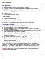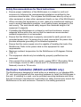
1
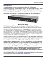
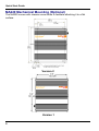
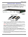
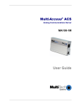
MultiAccess® ACS
Analog Communications Server
MA220
MA420
MA820
Quick Start Guide
MultiAccess ACS
MultiAccess ACS Quick Start Guide
MA220, MA420, MA820
P/N 82100102L, Revision C
All rights reserved. This publication may not be reproduced, in whole or in part,
without prior expressed written permission from Multi-Tech Systems, Inc.
Copyright © 2006-07 by Multi-Tech Systems, Inc.
Multi-Tech Systems, Inc. makes no representation or warranties with respect to
the contents hereof and specifically disclaims any implied warranties of
merchantability or fitness for any particular purpose. Furthermore, Multi-Tech
Systems, Inc. reserves the right to revise this publication and to make changes
from time to time in the content hereof without obligation of Multi-Tech Systems,
Inc., to notify any person or organization of such revisions or changes.
Record of Revisions
Revision
Date
A
B
C
Description
08/14/06 Initial release.
12/11/06 Changed TCP port number to 6000 and major
review.
07/13/07 Manual revised to include software version 1.03 and
added MA220 product.
Trademarks
MultiAccess, Multi-Tech, and the Multi-Tech logo are trademarks of Multi-Tech
Systems, Inc. All other brand and product names mentioned in this publication
are trademarks or registered trademarks of their respective companies.
Technical Support
Country
By Email
By Phone
France:
Europe, Asia, Africa:
U.S., Canada, all others:
support @multitech.fr
support @multitech.co.uk
support @multitech.com
+(33) 1-64 61 09 81
+(44) 118 959 7774
(800) 972-2439
+(763) 787-3500
World Headquarters
Multi-Tech Systems, Inc.
2205 Woodale Drive
Mounds View, Minnesota 55112 U.S.A.
(763) 785-3500 or (800) 328-9717
Fax (763) 785-9874
http://www.multitech.com
2
MultiAccess ACS
Introduction
This guide shows you how to setup your MultiAccess ACS analog
communication server, two-port model MA220, four-port model MA420 or eightport model MA820. All three units provide the same Remote Access Server,
RAS, and modem sharing capabilities except for the number of ports each can
provide. The MA420 and MA820 are provided in a desktop and rack mountable
units where as the MA220 is provided in a desktop and wall mountable unit.
MultiAccess MA820
The MultiAccess ACS has two roles (usage), RAS and Modem Sharing.
RAS Solution: The MultiAccess can be used as a dial-in PPP Remote Access
Server in a LAN to Client environment. The purpose is to give remote nodes
(i.e., Microsoft Dail-up Networking clients) TCP/IP access to the same subnet
and LAN the ACS is installed on. Masquerading (NAT) and LAN to LAN routing
(assignment of an entire subnet) are IP networking techniques not supported by
the ACS. The supported PPP security protocol (means of communicating user
credentials between PPP end points) is PAP only.
Modem Sharing Solution: The modems in the ACS can be a shared resource on
your network, commonly referred to as a network modem pool. Computers with
network asscess to the ACS can use Telnet and get direct AT command access
to one of the modems in the ACS, for either outbound or inbound calls. A
common way to take advantage of this role is by installing Com Port Redirector
Software (i.e., Multi-Tech’s MCSI2000 for Windows) on your workstations. The
redirector adds a virtual com port to the workstation and uses Telnet to map,
redirect, the com port to a modem in the ACS. The redirector and Telnet
session replaces the UART based hardware of a PC and serial cable
connection normally found in traditional modem installations. A communication
program using this virtual com port has its data redirected to and from the
modem within the ACS, making the modem appear as if it is directly attached to
a communication port on the workstation.
For the latest revision of the MultiAccess User Documentation, refer to the MultiTech Systems, Inc. Web site: http://www.multitech.com
3
Quick Start Guide
We Supply
• One MultiAccess unit with factory-installed software
• Two rack mounting brackets and four mounting screws for MA420 and
MA820
• One power cord for MA420 and MA820 or one universal power supply with
power cord for MA220
• A product CD
• This printed Quick Start Guide
You Supply
•
•
•
•
A nearby AC power outlet
A connection to your Ethernet LAN
Telephony connections
An admin PC (with web browser) to configure the MultiAccess
Safety Warnings
•
•
•
•
•
•
•
•
•
Use this product only with UL- and CUL-listed computers.
Never install phone wiring during a lightning storm.
Never install a phone jack in a wet location unless the jack is specifically
designed for wet locations.
Never touch uninsulated phone wires or terminals unless the phone line has
been disconnected at the network interface.
Use caution when installing or modifying phone lines.
Avoid using a phone during an electrical storm; there is a risk of electrical
shock from lightning.
Do not use a phone in the vicinity of a gas leak.
To reduce the risk of fire, use only 26 AWG or larger telephone line cord.
Disconnect this product from its power supply and telephone network
interface when servicing.
Caution: Danger of explosion if battery is incorrectly replaced. A lithium battery
on the MultiAccess PC board provides backup power for the time-keeping
capability. The battery has an estimated life expectancy of ten years. Contact
Multi-Tech if you suspect a failed battery. If data and time are incorrect after
having the unit powered off, it may be due to a weak battery or incorrect setup.
Caution: The Ethernet ports are not designed to be connected to a Public
Telecommunication Network.
4
MultiAccess ACS
Safety Recommendations for Rack Instructions
•
Ensure proper installation of the MultiAccess in a closed or multi-unit
enclosure by following the recommended installation as defined by the
enclosure manufacturer. Do not place the MultiAccess directly on top of
other equipment or place other equipment directly on top of the MultiAccess.
•
When mounting the equipment in a rack, make sure mechanical loading is
even to avoid a hazardous condition, such loading heavy equipment in the
rack evenly. The rack should safely support the combined weight of all
equipment it supports.
•
If installing the MultiAccess in a closed or multi-unit enclosure, ensure
adequate airflow within the rack so that the maximum recommended
ambient temperature is not exceeded.
•
Ensure that the MultiAccess is properly connected to earth ground via a
grounded power cord. If a power strip is used, ensure that the power strip
provides adequate grounding of the attached apparatus.
•
Ensure that the mains supply circuit is capable of handling the load of the
MultiAccess. Refer to the power label on the equipment for load
requirements.
•
Maximum ambient temperature for the MultiAccess is 60 degrees Celsius
(140° F).
•
This equipment should only be installed by properly qualified service
personnel.
•
Only connect like circuits. In other words, connect SELV (Secondary Extra
Low Voltage) circuits to SELV circuits and TN (Telecommunications
Network) circuits to TN circuits.
Hardware Installation (MA420 and MA820 only)
The MultiAccess is designed to install either on a desktop or in a standard EIA
19“ rack, and is shipped with the mounting hardware to install the MultiAccess in
the rack. If installing in a rack, use the provided mounting hardware and follow
the rack enclosure manufacturer’s instructions to safely and securely mount the
MultiAccess in the rack enclosure. Proceed to the cabling procedure.
5
Quick Start Guide
MA220 Mechanical Mounting (Optional)
The MA220 comes with chassis screw holes to facilitate attaching it to a flat
surface.
Version 2
Version 1
6
MultiAccess ACS
Cabling Procedure - Back Panel
Cabling your MultiAccess involves making the proper power, phone, and
ethernet connections as described below. The MultiAccess MA420 and MA820
back panels have a fan, a power plug, POWER Switch (| / O), four or eight RJ11 phone jacks, an Ethernet jack, and a Command jack. The MA220
backpanel has two LINE RJ-11 phone jacks, an Ethernet, LAN 1, and a
CONSOLE jack.
Back Panel – MA420
Back Panel – MA220
1.
2.
Plug one end of your RJ45 Ethernet cable into the Ethernet (MA420 &
MA820) or LAN 1 (MA220) jack on the back of the MultiAccess and the
other end to the hub on your local network.
Caution: Before connecting to the Ethernet network, make sure that the
network to which you are connecting the MultiAccess is not a 192.168.2.x
subnet. Because the MultiAccess’s factory default IP address is
192.168.2.1, connecting it to a network that has a different device at the
same IP address would cause data interference.
If it is a 192.168.2.x subnet, connect from the Administrative PC to the
MultiAccess using an RJ45 crossover cable until the MultiAccess’s IP
address has been configured. Afterwards, connect the MultiAccess into the
network with an ordinary RJ45 cable.
Using a standard telephone cable, connect one end of the cable to the first
RJ11 jack (1 or Line 1) on the back of the MultiAccess and the other end to
one of your phone jacks.
7
Quick Start Guide
3.
Continue to connect standard telephone cables to the remaining RJ11 jacks
on the back of the MultiAccess.
4
The Command or CONSOLE jack is to be used with direction from MultiTech’s Technical Support Personnel .
For the MA420 and MA820, ensure that the MultiAccess is securely and
permanently connected to an earth ground (GND) with a ground wire of 18
gauge (18 AWG) or thicker. The ground wire needs to be installed between
the grounding screw on the MultiAccess and a permanent earth ground.
In order for the earth ground to be considered permanent, the grounding
wire must connect to the earth ground of the building’s electrical wiring
system and the ground connection must use a screw terminal or other
reliable means of fastening. The ground connection must not be as easily
disconnected as, for example, a power cord.
5.
6.
On the MA220 unit, secure the power lead from the power source to the
screw-on power connection on the backpanel of the unit.
On the MA420 and MA820 units, with the MultiAccess Power switch in the
off (Ο) position and using the supplied power cord, connect the MultiAccess
power plug to a live power outlet.
7.
Place the MultiAccess Power switch to the on (|) position for the MA420 and
MA820 to turn on the MultiAccess. The MA220 does not have a power
switch.
Setting Admin PC to Startup IP Address
1.
2.
Connect a PC to your network. Record the PC’s current IP address.
Set the PC IP address to 192.168.2.x subnet (using any address
excluding 192.168.2.1).
Logging In
1. Bring up a Web browser on your PC. At the browser’s address line, type
the default IP address:
http://192.168.2.1 and press Enter.
2.
The Login screen will appear. At this point you can be assured that the
MultiAccess is connected to the network.
3.
At the Login screen, enter admin (all lower case) in the User Name field.
4.
Enter admin (all lower case) in the Password field.
5.
Click the Login button. The Home screen will appear. From this screen,
you can access all of the MultiAccess software screens.
8
MultiAccess ACS
Setting MultiAccess IP Addresses
1.
In the MultiAccess Administration screen, go to the IP Configuration
fields.
2.
Fill in the IP information that applies to your MultiAccess unit. The fields
for “IP Address,” “Subnet Mask,” “Default Gateway” and “Name Server”
are required. A “Secondary Name Server” may be considered optional.
3.
Click Update. After the Update button has been clicked, it takes 5
seconds for the page to update.
Resetting Admin PC to Its Original IP Address
In Setting the Admin PC to the network number of the MultiAccess, you
recorded the original IP address of the administrator’s PC and then reset it to
the IP address required to allow communication with the MultiAccess unit. You
may now set the IP address of the administrator’s PC back to its original value
or to any other value that will allow you to communicate with the MultiAccess at
its new IP address.
Log In Again
Having reset the IP address of the administrator’s PC, you must log into the
MultiAccess software again. Enter the MultiAccess’s new IP address into your
browser. The Login screen should appear.
Setting Up the Mail Server
1. From the Administration screen, go to the SMTP Configuration fields.
2.
Enter the mail server address in the SMTP Server Address window (e.g.,
mail.multitech.com).
3.
Enter the SMTP Port (usually 25) that is used by the SMTP Server.
9
Quick Start Guide
4.
Enter the E-mail address of the administrator in the Administrator E-mail
window.
5.
If the SMTP Server requires an User ID, enter the ID in the SMTP Server
User ID window.
6.
If the SMTP Server requires a password, enter the password in the SMTP
Password window.
7.
If you entered a password, retype the identical password in the Retype
SMTP Password window.
8.
Click on Update. At this point the MultiAccess will send the Administrator
an email saying that the mail server address has been updated.
Time Configuration
1. In the MultiAccess Administration screen, go to the Time Configuration
fields.
2. In the Time Server window, select from the three time server URLs. The
default is time.nist.gov. The Time Server is a substitute for a real-time clock
in the MultiAccess.
If you would like to add your own time server, you can enter the URL or IP
address of your time server in the Add Time Server window.
3. In the Request Interval window, select the Days, Hours, and Minutes that
the MultiAccess will update its clock from the time server.
4. If you are in daylight savings time, check the Use Daylight Savings Time
(DST) box.
5. In the Time Zone, Date Format, and Time Format windows, choose the
options for your time zone.
6. Click the update button to change to your new parameters.
10
MultiAccess ACS
Modem Configuration
There are two primary ways to use the modems; RAS and Modem Sharing.
Prior to software release version 1.03, the ports were configured for either RAS
or modem sharing, for which they were then dedicated to just that role. Now,
with software release version 1.03, the ports can be configured for both roles,
alleviating the need for administrator intervention when either role is desired.
The Modem Configuration fields define specific parameters per port. The
number of ports shown depends on the specific model of MultiAccess, POTS
modems 1 and 2 for the MA220, POTS modem 1 thru 4 if the model is the
MA420 or POTS modem 1 thru 8 if the model is the MA820.
The Modem Setup screen defines the Modem Sharing behavior and general
modem parameters, Country Code and number of rings before auto answer.
The TCP port, socket, number used by Telnet to access the modem is
dependent on how the Modem Sharing Pool option is used. If this option is set
to “pool”, port 6000 is used. All POTS modem ports set to pool, 6000, must
have the same exact Modem Sharing option, with or without authentication, etc.
When a Telnet client on the LAN opens a connection to 6000, it is given the
lowest number POTS modem port that is not in use.
If this Modem Sharing Pool option is set to “non-pool”, then a specific port
7000+ number is sequentially associated to each POTS modem, POTS modem
1 is assigned 7000, POTS modem 2 is assigned 7001 and so on incrementally
through POTS modem 8 with 7007 for a MA820 unit.
Modem Sharing with authentication means a login prompt will be issued to the
socket when it is opened. Who (what) ever opened the socket must provide
appropriate credentials before access is given to the modem. When access is
granted to the modem, an “ok” response message will be issued.
When Modem Sharing with Radius Authentication is selected, the Radius server
that will be used is defined in the Authentication menu.
When Modem Sharing with Local Authentication is selected, credentials (users)
shown in the Local Users menu are to be used.
When Modem Sharing with RAW is selected – support for RFC 2217 (com port
control via Telnet) will be disabled.
11
Quick Start Guide
1.
Select the desired Modem Sharing by clicking on the down arrow and
highlighting your usage.
No Authentication. Immediate access is given to the modem.
Local Authentication. A valid set of credentials, defined in the Local User
data base, is required before access is granted.
Radius Authentication. A valid set of credentials, defined in the Radius
User data base, is required before access is granted.
Raw Mode with No Authentication. User data is treated “as is”, without
interpretation, and no authentication is required.
Raw Mode with Local Authentication. User data is treated “as is”, without
interpretation, and a valid set of credentials, defined in the Local User data
base, is required before access is granted.
Modem Sharing – Raw Mode with Radius Authentication. User data is
treated “as is”, without interpretation, and a set of credentials, defined in the
Radius User data base, is required before access is granted.
2.
If Modem sharing Pool is set to pool, port 6000 is used. All POTS modem
ports set for pool must have the same exact Modem Sharing option.
If Modem Sharing Pool is set to non-pool, port 7000 is assigned to POTS
modem 1 port.
3.
Select your Country Code by clicking the down arrow and choose your
country/region.
4.
If the modem is being used for in-bound calls, select the number of ring(s)
for auto answer.
12
MultiAccess ACS
5.
If the modem usage is Modem Sharing and the calls are in-bound, click the
on option for the Caller ID.
6.
7.
Click Update for Modem Configuration: POTS modem x.
Repeat the above procedure for POTS modem 2 on the MA220, POTS
modems 2 thru 4 on the MA420 or POTS modems 2 through 8 for the
MA820.
Setting Authentication
The Authentication menu displays two ports for the MA220, four ports for the
model MA420 or eight ports for the model MA820. The Authentication/Radius
Client Configuration:POTS modem X fields allow you to select and define
certain user authentication details on a per port basis.
The Authentication Type option, on this menu, applies only to RAS, PPP, calls.
Please Note: When Modem Sharing, in Modem Setup, is configured to
implement Radius Authentication it will use the RADIUS Client details defined
here to authenticate the user, regardless of how the Authentication Type option
on this menu is set.
When the authentication method is local, use the Local User menu to build a
Database of user credentials. The MultiAccess matches the credentials
provided by the caller with the credentials listed in the Local User Database.
Additionally, local users can be configured for PPP call back.
When the Authentication Type is Radius, the MultiAccess sends the credentials
provided by the caller to the Radius Server for authorization.
For RAS calls, dial-in PPP, a second static IP address is needed in the Remote
Host Address field. This address is for the dial-in user, PPP peer. This address
needs to be on the same subnet, network number, as that of the MultiAccess.
13
Quick Start Guide
When the authentication method is Radius, then the IP address and UDP port of
the Radius Server and Radius Accounting Server have to be entered and the
Secret has to be entered.
Radius accounting begins after successful Radius authentication. Radius
accounting summarizes the time and date, duration, POTS port connected and
the IP address given to the user for the call. Radius accounting does not track
the amount or type of data of the session or the places the user communicates
with.
The Secret is an MD5 encryption key used by both the Radius Server and
Radius Client, MultiAccess. It must be the same alphanumeric string, including
case that is defined in the Radius Sever.
Authentication / Radius Client Configuration: POTS modem x
1. In the Authentication Type, if your database for user credientals resides in
the Local User Database on the MultiAccess, then accept the default –
local.
If your user database is external to the MultiAccess, then click on the
down arrow and choose radius.
2. For RAS calls, enter an available IP Address from your existing network
scheme in the Remote Host Address window which will be assigned to
the dial-in user. This remote host address has to match the network
number that the MultiAccess is on.
3. If you are setting up MultiAccess to use Radius Authentication, then enter
the IP address of the primary RADIUS Server in the RADIUS Server
Address window.
4.
Enter the port number (usually 1812) for this Radius Server in the Port
window across from the server address you just entered. The Radius
Server has to be listening on the same UDP port that the Radius Client,
MultiAccess, is using.
5.
Enter the IP address of the Radius Accounting server in the RADIUS
Accounting Address window.
6.
Enter the port number (usually 1813) for the Radius Accounting server in
the Port window across from the accounting address you just entered.
The Radius Accounting Server has to be listening on the same UDP port
that the Radius Client, MultiAccess, is using.
7. Enter the Secret of the Radius Server that you are communicating with.
The Secret has to be indentical to the one used by your Radius Server and
is limited to 14 alphanumeric characters.
14
MultiAccess ACS
8. Repeat the above procedure for POTS modem 2 on the MA220, POTS
modems 2 through 4 on the MA420, or POTS modems 2 through 8 on the
MA820.
Setting Up Local Users
The administrator builds the Local Users data base defining the Name field,
recording the User ID, Password entries, and callback method. The
administrator account has both administration of the MultiAccess, dial-in and
dial-out rights. Local User accounts have dial-in and dial-out rights to use the
modems. Remote users enter their user ID and password at the beginning of
the dial-in session.
For Local Authentication, go to the Local Users screen.
Note: The first row is for the “Administrator” function. No matter what values
are used for the Name, User ID and Password fields, the first row will
still apply to the person doing the Administrator function for the
MultiAccess. The Administrator is the party privileged to configure the
MultiAccess.
Note: Callback Security can be implemented in two ways: 1) a fixed
telephone number by choosing Admin specified in the Callback window
and enterring the telephone number in the Callback Number field. 2) a
variable telephone number by choosing User specified in the Callback
window. If a variable telephone number is chosen, then no telephone
number is entered in the Callback Number field.
Administator Row:
1.
In the “Administrator” row of the Local Users screen, enter the Name and
User ID to be used for the MultiAccess administrator (it need not be literally
“Administrator”).
2.
In the Password window, enter an alphanumeric password. Passwords
can be as long as 21 characters, and are case-sensitive.
3.
In the Confirm Password window, enter the identical alphanumeric
password.
15
Quick Start Guide
4.
Caution: If you change the password, you must be sure you remember
your new password.
If the administrator account is going to have the Callback feature enabled,
click on the Callback down arrow and choose the callback method, fixed
phone number is Admin specified or variable phone number is User
specified.
If the Callback Security option is enabled and Admin specified is
selected, then enter the fixed telephone number of the site you will be
originating (calling) from in the Callback Number window.
If the Callback Security option is enabled and User specified is selected,
you do not enter a telephone number in the Callback Number window.
The callback telephone number is entered during the dail-in process.
5.
Click on Update in the “Administrator” row. At this point, a Login screen
will appear and you will be asked to log in again. Log in using the
administrator’s User ID (as listed in the “User ID” column) and the
administrator’s current password.
Users Row:
1.
In the next blank Name row, enter the Name and User ID of your local
user.
2.
In the Password window, enter an alphanumeric password. Passwords
can be as long as 21 characters, and are case-sensitive.
3.
In the Confirm Password window, enter the identical alphanumeric
password.
If you are going to enable the Callback Security option for a remote user,
click on the Callback down arrow and choose the callback method. Fixed
phone number is Admin specified or variable phone number is User
specified. User specified allows the remote user to enter his/her changing
telephone number during the dial-in session.
4.
If the Callback Security option is enabled and Admin specified is
selected, then enter the fixed telephone number the user will always be
dialing from in the Callback Number window.
If the Callback Security option is enabled and User specified is selected,
you do not enter a telephone number in the Callback Number window.
The remote user enters the callback number during the dial-in session.
5.
6.
16
Click the add button to include this local user in the data base.
Repeat the Local User Row steps for each local user you want to add to
your local user data base.
MultiAccess ACS
17
Patents
This device is covered by one or more of the following patents: 6,031,867; 6,012,113; 6,009,082;
5,905,794; 5,864,560; 5,815,567; 5,815,503; 5,812,534; 5,809,068; 5,790,532; 5,764,628; 5,764,627;
5,754,589; D394,250; 5,724,356; 5,673,268; 5,673,257; 5,644,594; 5,628,030; 5,619,508; 5,617,423;
5,600,649; 5,592,586; 5,577,041; 5,574,725; D374,222; 5,559,793; 5,546,448; 5,546,395; 5,535,204;
5,500,859; 5,471,470; 5,463,616; 5,453,986; 5,452,289; 5,450,425; D361,764; D355,658; D355,653;
D353,598; D353,144; 5,355,365; 5,309,562; 5,301,274. Other patents pending.
82100102L