1
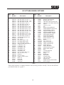
OPERATORS MANUAL MODEL GC-STT-6KH 71 27 62 50 20 22 18 51 35 34 6 17 15 28 22 17 22 22 28 29 49 19 2 36 14 10 22 60 03054cover THIS MANUAL CONTAINS THE OPERATING INSTRUCTIONS AND SAFETY INFORMATION FOR YOUR SCAG ACCESSORY. READING THIS MANUAL WILL PROVIDE YOU WITH MAINTENANCE AND ADJUSTMENT PROCEDURES TO KEEP YOUR ACCESSORY PERFORMING TO MAXIMUM EFFICIENCY. THE SPECIFIC MODELS THAT THIS BOOK COVERS ARE CONTAINED ON THE INSIDE COVER. BEFORE OPERATING YOUR MACHINE, PLEASE READ ALL THE INFORMATION ENCLOSED. PART NUMBER 03065 WARNING FAILURE TO FOLLOW SAFE OPERATING PRACTICES MAY RESULT IN SERIOUS INJURY. * Keep all safety shields in place. * Before performing any maintenance or service, stop the machine and remove the spark plug wire. * If a mechanism becomes clogged, stop the engine before cleaning. * Keep hands, feet and clothing away from power-driven parts. * Read this manual completely as well as the Operator's Manual that came with your mower. * Keep others off the tractor (only one person at a time). REMEMBER - YOUR MOWER IS ONLY AS SAFE AS THE OPERATOR! Hazard control and accident prevention are dependent upon the awareness, concern, prudence, and proper training of the personnel involved in the operation, transport, maintenance, and storage of the equipment. This manual covers the operating instructions and illustrated parts list for: GC-STT-6KH with a serial number of 4590001-4599999 Always use the entire serial number listed on the serial number tag when referring to this product. ® TABLE OF CONTENTS SUBJECT PAGE 1.1 Introduction ........................................................................................................ 1 1.2 Direction Reference .......................................................................................... 1 1.3 Servicing The Engine ......................................................................................... 1 2.1 Safety and Operating Instructions ..................................................................... 1 3.1 Assembly Instructions ....................................................................................... 2 3.2 Discharge Boot Assembly ................................................................................. 2 3.3 Catcher Frame Assembly .................................................................................. 3 3.4 Bucket Cover Assembly ................................................................................... 4 3.5 Engine Mounting ................................................................................................ 4-5 3.6 Catcher Hose Installation .................................................................................. 5 3.7 Weight Bar Installation ....................................................................................... 5 Illustrated Parts List ................................................................................................. 6-7 Limited Warranty Statement................................................................... Inside Back Cover MEMBER c Equipment & Engine Training Council WE SUPPORT OPE TECHNICIAN CERTIFICATION I 1.1 INTRODUCTION 2.1 SAFETY AND OPERATING INSTRUCTIONS This manual has been prepared to provide the information you need to correctly assemble, operate, and maintain this grass catcher. Read it carefully and keep it for future reference. -NoteTo avoid personal injury, it is imperative that all safety instructions be observed. 1. Read this operator's manual and the operator's manual that is supplied with the machine this attachment is used on. The replacement of any part on this product by other than the manufacturer's authorized replacement part may adversely affect the performance, durability or safety of this product. A replacement manual is available from your authorized Scag Service Dealer or by contacting: Scag Power Equipment, Service Department at P.O. Box 152, Mayville, WI 53050. Please indicate the complete model and serial number of your Scag product when ordering a replacement manual. USE OF OTHER THAN ORIGINAL SCAG REPLACEMENT PARTS WILL VOID THE WARRANTY. If additional information or service is needed that is not outlined in this manual, please contact your Scag Power Equipment dealer. Scag dealers are trained in the latest service methods and carry a full line of Scag replacement parts. 2. Never operate your mower without the complete grass catcher, all guards and covers installed, or the discharge chute properly installed. When ordering parts, always provide the complete model and serial number of your catcher. 3. Before removing the grass bucket, disengage the mower, stop the engine on both the mower and the grass catcher, and wait for all movement to stop. All information provided in this manual is based upon information available at the time of printing. Scag Power Equipment reserves the right to make chages at any time without notice or obligation. 4. ALWAYS turn the engine OFF, remove the key and wait for all movement to stop before servicing or cleaning the mower or the grass catcher. 1.2 DIRECTION REFERENCE 5. Do not modify or alter any component of the grass catcher attachment. The "Right" and "Left", "Front" and "Rear" of the machine are referenced from the normal operating position. 6. Do not allow any passengers to ride on the grass catcher attachment or on the mower. 1.3 SERVICING THE ENGINE 7. To reduce the risk of fire, keep the engine clean and free of debris, or excess lubricants. The detailed servicing of the engine is not covered in this manual. For service of the engine it is important to contact your Scag Dealer or an authorized servicing 8. DO NOT add fuel to a running or hot engine. agent of the engine manufacturer. Any unauthorized Turn the engine OFF and allow it to cool before work done on the engine will void the warranty. re-fueling. 1 3.1 ASSEMBLY INSTRUCTIONS -NoteIf you are installing the catcher to a machine with a 52" cutter deck, you must install the filler plate (item 42) to the boot. -NoteFor any instructions referring to an item number, refer to the illustrated parts breakdown on pages 6 and 7. Use the illustrated parts list as a reference when following the assembly instructions. 4. Install the filler plate (item 42) to the boot (52" models only) in the rearward holes in the boot using (2) 5/16-18 x 3/4" bolts, (2) 5/16" flat washers and (2) 5/16-18 elastic stop nuts. 1. Remove all packaging materials. Lay out the mounting hardware and the catcher assembly parts for easy access. -NoteIf you are installing the catcher to a machine with a Bahia cutter deck you must also install the filler plate (item 43) to the cutter deck. 3.2 DISCHARGE BOOT ASSEMBLY 1. If your cutter deck does not have the two discharge chute mounting holes, locate and center punch the two hole locations in the cutter deck as shown in figure 1. Drill the holes at the marked locations using a 1/8" drill bit, then finish drilling using a 13/32" drill bit. 5. Hold the filler plate to the front of the cutter deck as shown in figure 2. Center punch the two hole locations in the cutter deck. Drill the holes at the marked locations using a 1/8" drill bit, then finish drilling using a 9/32" drill bit. 9" 4.25" 03054126982 Center punch and drill these two holes. 0305412698 3/4" Align the front edge of the filler plate with the front edge of the cutter deck. Figure 2, Bahia Filler Plate 6. Install the deck filler plate (item 43) to the inside front of the Bahia deck (52" & 61" Bahia decks only), using (2) 1/4-20 x 3/4' bolts and (2) 1/4" x 20 elastic stop nuts. Figure 1, Hole Locations 2. Install the boot mounting support tabs (items 40 & 41) to the cutter deck, using (1) 5/16-18 x 1" bolt, (1) 5/16-18 x 1-1/4" bolt and (2) 5/16-18 elastic stop nuts. Do not tighten the bolts at this time. 7. Install the boot to the cutter deck by aligning the holes in the boot mounting bracket with the holes in the boot mounting support tabs. 3. Install the boot mounting bracket (item 39) to the boot (item 66) in the holes toward the front of the boot, using (2) 3/8-16 x 1" bolts, (2) 3/8" flat washers and (2) 3/8-16 elastic stop nuts. 8. Secure the boot to the cutter deck by inserting the chute latch pin (item 45) through the holes in the support tabs and the boot mounting bracket. Secure the pin using the cotter pin provided in the hardware package. Tighten the boot mounting support tab bolts. 2 3.3 CATCHER FRAME ASSEMBLY 8. Slide the engine support frame (item 54) under the catcher frame and install onto the bolts that are inserted into the RH upright post and the catcher frame. Secure using (2) 3/8-16 elastic stop nuts and (2) 3/8" flat washers. 1. On the LH side of the machine remove the two bolts securing the pump mounting plate to the machine. Align the holes in the hitch bracket weldment (item 53) with the holes in the machine frame. Install (2) 3/8-16 x 1-1/4" bolts into the rear holes of the frame and the hitch bracket. Install (2) 3/8-16 x 1" bolts into the front holes. Secure using four 3/8-16 elastic stop nuts. 9. Install the LH upright support weldment (item 50) to the LH side of the catcher frame. Insert (2) 3/8-16 x 3-1/2" bolts and (2) 3/8" flatwashers into the holes of the upright post, the catcher frame and the engine support frame. Secure using (2) 3/8-16 elastic stop nuts and (2) 3/8" flat washers. -NoteInstall the hitch bracket mounting hardware from the inside of the machine through the machine frame and then through the hitch bracket. This will prevent the hardware from interfering with the linkage. 10. Install the LH brace (item 35) to the LH upright post. Secure using (1) 5/16-18 x 2" bolt, (1) 5/16" flat washer and (1) 5/16-18 elastic stop nut. Secure the other end of the LH brace to the catcher frame using (1) 5/16-18 x 1" bolt and (1) 5/16-18 elastic stop nut. 2. Repeat step 10 on the RH side of the machine. 3. Install the 1/2-13 nut (item 19) onto the 1/2-13 x 1-1/2" bolt (item 14). Thread the bolt and nut assembly into the boss on the catcher frame (item 49). Do not tighten at this time. 11. Install (1) 5/16-18 nut onto the eyebolt (item 34). Install the eyebolt through the LH upright support and secure with (1) 5/16-18 elastic stop nut. 4. Align the pins on the catcher frame (item 49) with the hitch brackets. Slide the catcher frame into the tubes on the hitch brackets and secure using the quick pins (item 32). 12. Install the heatshield (item 37) to the catcher frame using (1) 5/16-18 x 3/4" carriage bolt, (1) 5/16" flat washer and (1) 5/16-18 elastic stop nut. R O P E R Y L 5. Adjust the 1/2-13 nut and bolt assembly, that P E C R E V I was installed onto the catcher frame in step 3 ,S E N N G E I so the head of the bolt rests against the belt cover W T H I on the machine. Tighten the nut against the boss to secure the bolt from moving. OL I 13. Secure the 2 heatshields to the two upright supports using (6) 5/16-18 x 3/4" carriage bolts, (6) 5/16-18 elastic stop nuts. The heatshields will mount on the outside of the supports and have an air space between them when installed properly. A N D 6. Align the holes in the RH upright post weldment FUEL. (item 51) with the holes on the RH side of the catcher frame. Place (2) 3/8" flat washers onto (2) 3/8-16 x 3-1/2" bolts and insert the bolts into the holes of the upright post and the catcher frame. 14. Slide the bucket (item 57) onto the catcher frame and secure using the rubber strap (item 62). Hook one end of the rubber strap into the washer welded onto the RH upright support and the other end into the eyebolt bolted onto the LH upright support. 7. Install the RH brace (item 36) to the RH upright post. Secure using (1) 5/16-18 x 2-1/2" bolt, (1) 5/16" flat washer and (1) 5/16-18 elastic stop nut. Secure the other end of the RH brace to the catcher frame using (1) 5/16-18 x 1" bolt and (1) 5/16-18 elastic stop nut. 3 6. Align the rear set of holes in the cover bracket weldment with the holes in the RH upright support. Secure the cover bracket to the RH support using (1) 3/8-16 x 2-1/2" bolt, (2) 3/8" flat washers and (1) 3/8-16 elastic stop nut. Do not overtighten. The cover must be allowed to pivot on the upright support. 3.4 BUCKET COVER ASSEMBLY 1. Align the holes in the filter frame (item 74) with the holes in the molded top (item 70). Be sure the venting slots are pointed away from the operator. (see figure 3) 2. Align the three holes in the cover bracket weldment (item 56) with the correct three holes in the filter frame and the molded top as shown in figure 3. CAUTION: Springs will become energized during installation, use caution when installing. Bucket Cover Cover Bucket Filter Frame 7. Pivot the molded top up and back allowing the two spring anchors to become close enough to install the two springs (item 69) onto the spring anchors. Place the springs on the outside edge of the anchors, so the bolts do not interfere. Pivot the molded top down onto the catcher bucket. Spring Anchor Spring RH Upright Support Do Not Overtighten Use One 1/4" Flat Washer Between Bucket Cover & Elastic Stop Nut Venting Slots Opening Away From Operator 8. Install (1) 3/8-16 x 2-1/2" bolt into the set of holes located next to the pivot bolt in the cover bracket weldment. Secure using (1) 3/8-16 elastic stop nut. Location of 1/4" Spacer Between Cover Bracket & Filter Frame GCSTT99BT Figure 3, Bucket Top -NoteThis bolt must be installed to prevent the bucket cover from flipping over. 3. Install the 1/4" spacer (item 44) between the cover bracket weldment and the filter frame at the hole closest to where the cover bracket mounts to the RH upright support. Insert (1) 1/4-20 x 1" bolt through the cover bracket, 1/4" spacer, filter frame and molded top. Secure using (1) 1/4" flat washer and (1) 1/4-20 elastic stop nut. 9. Install the container latch (item 72) onto the LH side of the molded top. Secure using (2) 1/4-20 x 1" bolts, (4) 1/4" flat washers and (2) 1/4-20 elastic stop nuts. Adjust the latch as necessary to insure a tight fit between the cover and the bucket. 3.5 ENGINE MOUNTING 4. Finish securing the cover bracket and the filter frame to the molded top using the (7) 1/4-20 x 1" bolts, (14) 1/4" flat washers, and (7) 1/4-20 elastic stop nuts. Use one flat washer by the head of each bolt and one by each elastic stop nut. 5. Install the grass filter (item 73) around the filter frame. The elastic in the filter will go around the lip that circles the filter frame located inside the molded top. 1. Align the holes in the engine guard weldment (item 55) with the mounting holes in the engine. Insert (4) 5/16-18 x 1-3/4" bolts through the holes in the engine and the engine guard weldment. 4 2. Align the bolts that were inserted through the engine and engine guard weldment with the holes in the engine mounting frame (item 54). Insert all four bolts into the holes in the engine mounting frame and secure using (4) 5/16-18 elastic stop nuts. 3. Attach the engine exhaust deflector (item 64) with the two screws provided, so that the exhaust is deflected downward and at an angle away from the operator. 4. Install the blower housing weldment (item 47) to the engine using (4) 5/16-24 x 1" bolts and (4) 5/16" lockwashers. 5. Install the fan assembly (item 46) and key (item 31) to the engine crankshaft and secure using (1) 7/16-20 x 2" fine thread bolt, (1) 7/16" lock washer and (1) 7/16" flat washer. Torque the retaining bolt to 55 ft.lbs. 6. Install the inlet adaptor (item 48) to the blower housing using (6) 5/16-18 wing nuts. 4. Install the 8" inlet hose onto the boot and secure using the hose clamp. Install the free end of the 8" hose onto the inlet adaptor and secure using the hose clamp. -NoteWhen installing the STT Catcher onto a 52" cutter deck, Approximately 6" of the hose will need to cut off of the 8" inlet hose. 3.7 WEIGHT BAR INSTALLATION 1. Install the weight support bar (item 52) to the front of the machine by resting it directly on top of the caster support arms and sliding it tight against the frame of the machine. Secure the weight bar to the machine using (2) bar clamps (item 38), (4) 3/8-16 x 1-1/2" bolts and (4) 3/8-16 elastic stop nuts. 2. Install the weight assemblies (item 75) to the weight support bar and secure them to the bar using the 1/2"x 6-1/4" pin and lanyard (item 33 & 67). -NoteAdditional weight assemblies are available through your Scag dealer. -NoteIn order to prevent hot exhaust blowing on the grass catcher engine you must remove the exhaust pipe that is mounted to the muffler on the main engine. 3.6 CATCHER HOSE INSTALLATION 1. Slide (1) 6-1/2" hose clamp (item 60) onto one end of the 6" hose (item 58). 2. Slide (1) 6-1/2" hose clamp (item 60) onto the other end of the 6" hose (item 58) and install onto the blower housing outlet and secure using the hose clamp. 3. Slide (2) 8-5/8" hose clamps onto the ends of the 8" hose (item 59). 5 GC-STT-6KH GRASS CATCHER 56 69 5 27 21 44 21 74 5 29 27 20 29 9 73 75 70 72 21 27 57 62 38 22 50 20 33 67 18 51 69 35 34 6 37 17 22 17 28 8 52 15 22 28 12 22 28 60 71 22 29 2 32 49 19 36 10 14 7 43 22 55 11 60 A 20 41 40 53 58 21 42 28 29 21 54 22 22 22 2 21 3 4 61 A 65 64 13 61 46 31 48 76 23 24 26 25 GCSTT99EXV 6 45 29 66 7 16 30 39 59 47 63 1 GC-STT-6KH GRASS CATCHER Ref. No. 1 2 3 4 5 6 7 8 9 10 11 12 13 14 15 16 17 18 19 20 21 22 23 24 25 26 27 28 29 30 31 32 33 34 35 36 37 38 Part Number 04001-01 04001-09 04001-10 04001-12 04001-14 04001-17 04001-19 04001-20 04001-31 04001-32 04001-38 04001-53 04001-56 04001-71 04001-77 04001-88 04003-12 04020-03 04020-07 04021-08 04021-09 04021-10 04022-02 04030-03 04030-05 04040-11 04040-14 04040-15 04041-07 04062-02 04063-06 04066-03 04067-06 04070-04 422578 422579 422580 422586 Ref. No. Description 39 40 41 42 43 44 45 46 47 48 49 50 51 52 53 54 55 56 57 58 59 60 61 62 63 64 65 66 67 68 69 70 71 72 73 74 75 76 Bolt, Hex Head, 1/4-20 x 3/4” Bolt, Hex Head, 5/16-18 x 1” Bolt, Hex Head, 5/16-18 x 1-1/4” Bolt, Hex Head, 5/16-18 x 1-3/4” Bolt, Hex Head, 1/4-20 x 1” Bolt, Hex Head, 5/16-18 x 2” Bolt, Hex Head, 3/8-16 x 1” Bolt, Hex Head, 3/8-16 x 1-1/2” Bolt, Hex Head, 3/8-16 x 2-1/2” Bolt, Hex Head, 3/8-16 x 1-1/4” Bolt, Hex Head, 5/16-18 x 3/4” Bolt, Hex Head, 5/16-18 x 2-1/2” Bolt, Hex Head, 5/16-24 x 1” Bolt, Hex Head, 1/2-13 x 1-1/2” Bolt, Hex Head, 3/8-16 x 3-1/2” Bolt, Hex Head, 7/16-20 x 2” Carriage Bolt, 5/16-18 x 3/4” Nut, 5/16-18” Nut, 1/2-13” Nut, Elastic Stop, 1/4-20” Nut, Elastic Stop, 3/8-16” Nut, Elastic Stop, 5/16-18” Wingnut, Elastic Stop, 5/16-18” Lockwasher, 5/16” Lockwasher, 7/16” Flat Washer, 7/16” Flat Washer, 1/4” Flat Washer, 5/16” Flat Washer, 3/8” Hair Pin Cotter, .080 x 1.19” Key, 1/4 x 1/4 x 1-1/2” Quick Pin Pin, 1/2 x 6-1/4” Eyebolt, 5/16-18 x 2-3/4” Brace, LH Brace, RH Heatshield Clamp, Bar Part Number 422588 422589 422590 422591 422592 43063 44131 45077 45080 45081 451023 451024 451025 451026 451027 45371 45374 45429 48133 48135-04 48135-09 48136-01 48136-02 48137-01 481564 481697 481698 481734 481737 48236 48734 481745 422725 48737 48738 48739 9009 48236 Description Mounting Bracket, Chute Support, Chute Mounting Mounting Tab, Chute Filler Plate, Chute-52” Deck Only Filler Plate, Chute-Bahia Deck Only Spacer Latch Pin, Chute Fan Blower Housing Weldment Adapter Weldment, Blower Inlet Frame Weldment, Catcher Upright Post Weldment, LH Upright Post Weldment, RH Support Weldment, Weights Hitch Bracket Weldment Engine Mounting Frame Engine Guard Weldment Bracket Weldment, Cover Bucket Hose, 6” Dia x 34” Hose, 8” Dia x 53” Clamp, 6-1/2” Max Dia Clamp, 8-5/8” Max Dia Rubber Strap-34” Engine, 6HP Kohler Exhaust Deflector, Engine Screw, Kohler Special Boot Lanyard, Weight Pin Decal, Danger Spring Molded Top Heat Shield Container Latch Filter, Open Mesh Support, Filter Weight Assembly, GC-STT-6KH Decal, Danger -NoteSome of the hardware is common hardware and you may purchase it locally. Be sure that all bolts purchased locally are a grade 5. 7 LIMITED WARRANTY- COMMERCIAL A CCESSOR Y ACCESSOR CCESSORY Any part of the Scag commercial accessory manufactured by Scag and found, in the reasonable judgment of Scag, to be defective in material or workmanship, will be repaired or replaced by an Authorized Scag Service Dealer without charge for parts and labor. The Scag accessory, including any defective part, must be returned to an Authorized Scag Service Dealer within the warranty period. The expense of delivering the accessory to the dealer for warranty work and the expense of returning it back to the owner after repair or replacement will be paid for by the owner. Scag’s responsibility in respect to claims is limited to making the required repairs or replacements, and no claim of breach of warranty shall be cause for cancellation or rescission of the contract of sale of any Scag machine. Proof of purchase will be required by the dealer to substantiate any warranty claim. All warranty work must be performed by an Authorized Scag Service Dealer. This warranty is limited to 90 days from the date of original retail purchase for any Scag accessory that is used for commercial purposes, or any other income-producing purpose including rental use. This warranty does not cover any accessory that has been subject to misuse, neglect, negligence, or accident, or that has been operated in any way contrary to the operating instructions as specified in the Operator's Manual. The warranty does not apply to any damage to the accessory that is the result of improper maintenance, or to any accessory or parts that have not been assembled or installed as specified in the Operator's Manual. The warranty does not cover any accessory that has been altered or modified. In addition, the warranty does not extend to repairs made necessary by normal wear, or by the use of parts or accessories which, in the reasonable judgment of Scag, are either incompatible with the Scag mower or adversely affect its operation, performance or durability. This warranty does not cover engines and electric starters, which are warranted separately by their manufacturer. Scag Power Equipment reserves the right to change or improve the design of any accessory without assuming any obligation to modify any accessory previously manufactured. All other implied warranties are limited in duration to the 90 day warranty period. Accordingly, any such implied warranties including merchantability, fitness for a particular purpose, or otherwise, are disclaimed in their entirety after the expiration of the appropriate ninety day warranty period. Scag’s obligation under this warranty is strictly and exclusively limited to the repair or replacement of defective parts and Scag does not assume or authorize anyone to assume for them any other obligation. Some states do not allow limitations on how long an implied warranty lasts, so the above limitation may not apply to you. Scag assumes no responsibility for incidental, consequential or other damages including, but not limited to, expense for gasoline, oil, expense of delivering the machine to an Authorized Scag Service Dealer and expense of returning it back to the owner, mechanic’s travel time, telephone or telegram charges, rental of a like product during the time warranty repairs are being performed, travel, loss or damage to personal property, loss of revenue, loss of use of the mower, loss of time, or inconvenience. Some states do not allow the exclusion or limitation of incidental or consequential damages, so the above limitation or exclusion may not apply to you. This warranty gives you specific legal rights, and you may also have other rights which vary from state to state. © 1998 SCAG POWER EQUIPMENT DIVISION OF METALCRAFT OF MAYVILLE, INC PART NO. 03065 PRINTED 8/98 PRINTED IN USA