1
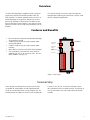
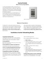
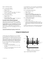
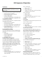
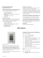
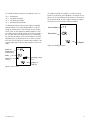
DDC Controls Package Manual
VHC-36, -42 and -50
Operation Instructions Manual
Model: VHC-36, VHC-42, VHC-50
©2009 Venmar CES Inc.
Table of Contents
Overview...............................................................................................................................................................................3
Features and Benefits..........................................................................................................................................................3
Terminal Strip.................................................................................................................................................................3
Control Details......................................................................................................................................................................4
Stand Alone Operation..................................................................................................................................................4
Network Operation........................................................................................................................................................4
Ventilation Control Scheduling Modes...............................................................................................................................4
Temperature Control Configuration...................................................................................................................................5
Setpoint Adjustment............................................................................................................................................................6
VHC Sequence of Operation................................................................................................................................................7
DDC Interface.....................................................................................................................................................................11
Appendix A: Control Wiring Connections Example.........................................................................................................13
Appendix B: DDC Points Reference Guide........................................................................................................................16
Appendix C: Standard Network Practice..........................................................................................................................19
Appendix D: DDC Troubleshooting Guide........................................................................................................................21
©Venmar CES Inc. 2012. All rights reserved throughout the world.
Illustrations cover the general appearance of Venmar CES products at the time of publication and Venmar CES reserves the
right to make changes in design and construction at any time without notice.
™® The following are trademarks or registered trademarks of their respective companies: Variable Refrigerant Control from
Venmar CES.
CES Group, LLC d/b/a Venmar CES furnishes equipment pursuant to its then-current Terms and Conditions of Sale and Limited Warranty, copies of which can be found under the Terms & Conditions of Sale and Warranty link at www.ces-group.com.
Extended warranties, if any, shall be as offered and acknowledged in writing by Venmar CES.
Manufacturer reserves the right to discontinue or change specifications or designs without notice or obligation.
VCES-DDC-IOM-1C
2
Overview
The DDC control package is programmed for a range of
temperature control and scheduling modes which are
field selectable. The control package enables the VHC to
control discharge air temperature, room/return air temperature or discharge in conjunction with room air temperature based on sensor readings. It can also be used to
control the amount of air being recirculated back into the
building.
This manual provides instructions and information on
configuring and adjusting the control for a specific stand
alone or networking application.
Features and Benefits
•
•
•
•
•
No extra controls needed to accommodate discharge
air temperature control.
A room thermostat may be used to control room
heating and cooling.
A room humidistat may be used to control room
humidity.
Native BACnet firmware with MS/TP RS485 protocol.
Can be optionally interfaced with many different
protocols with the use of a terminal server, like Lonworks, Modbus, Metasys, etc.
Net 1 BacNet
terminals
Net 2 LinkNet
terminals
Net 1 jumper
setting
BacNet address
jumpers
DDC outputs
DDC inputs
Figure 1: DDC layout
Terminal Strip
A low voltage Field Wiring (FW) interface terminal strip
is provided for shipped loose or field supplied controls,
sensor or interlock connections to fully integrate the unit.
Interconnections to a BMS are minimal. Refer to Appendix
VCES-DDC-IOM-1C
G and H in the VHC-36, 42 and 50 Installation, Operation and Maintenance Instructions Manual, for example of
start-up connections, plus input and output connections
available.
3
Control Details
Stand Alone Operation
The DDC control package includes a four-button user interface called the BacStat II. This device can be mounted
anywhere and when room air tempering is needed, can be
configured as a room thermostat. A wide range of configuration options are included and can be accessed through
the BacStat (see Figure 2).
For stand alone operation an external dry contact (ex: remote time clock, CO2 sensor or manual selector switch,
etc.) for scheduling mode must be provided by others or is
available as an accessory item. This is the only connection
required to start single-speed units.
Figure 2: BacStat II
Network Operation
The Delta DDC is a native BACnet device that can communicate over an RS-485 network running between 9,600
and 76,800 baud. Delta products are tested for interoperability between multiple vendors at the BACnet Testing
Laboratory (BTL). The use of a BTL listed front end will
greatly simplify network installation and allow problemfree
communication.
When connected to the network, all scheduling can be
taken over by the front end control system (provided by
others). Additional access is provided to dozens of control
variables which give the Building Management System
as much control as needed (with the exception of critical
functions, such as the defrost strategy and other fail safes).
Ventilation Control Scheduling Modes
Occupied Ventilation (Ov)
Adjust the following parameters:
Jumper across FW 304–305. This is the main mode that
will enable the unit to run in 100% fresh air mode. Free
cooling and defrost will initiate based on the setpoint.
#143 – Outside Air Damper Minimum Setpoint
• Limits: 0–100%
• Factory set: 100%
• BACnet variable: AV150
• Function: The outside air damper minimum setpoint
is set in conjunction with the exhaust air damper
minimum setpoint to allow for the required recirculation air.
#144 – Exhaust Air Damper Minimum Setpoint
• Limits: 0–100%
• Factory set: 100%
• BACnet variable: AV151
• Function: The exhaust air damper minimum setpoint
is set in conjunction with the outside air damper
minimum setpoint to allow for the required recirculation air.
Unoccupied (Un)
No jumpers on any of the terminals 304, 305, 306, 307 or
308. The unit will turn off.
Unoccupied Recirculation (Ur) (Optional)
Jumper across FW 305–306. The unit will turn off unless there is a call for heating/cooling or dehumidification
across the heating/cooling or dehumidification contacts.
This call must come from an optional thermostat or humidistat. The unit will run in recirc mode upon a call.
Occupied Recirculation (Or) (Optional)
Jumper across FW 306–307. The unit will run and recirc
a percentage of air. The outside and exhaust air dampers
may be adjusted to open a certain percentage, thus reducing the amount of fresh air and increasing the amount or
recirc air.
VCES-DDC-IOM-1C
Building Management System Scheduling
Alternatively the software point MV12 can be used to
schedule the unit as described above. If this method is
4
being used then you must not provide any jumpers to terminals 304, 305, 306, 307 or 308.
The remote unit control multi-state variable is used to enable the unit through a Bacnet interface. Set MV12 to:
•
•
•
•
2 for unoccupied mode.
4 for occupied recirculation mode (optional).
6 for unoccupied recirculation mode (optional).
10 for ventilation mode.
Temperature Control Configuration
The VHC unit can be configured to control building temperature a variety of ways. Adjust #153 – Zone Configuration to change temperature control to discharge air, room
air or return air control. Default settings from factory allow
the unit to be controlled by discharge air temperature.
Adjust the following setpoint:
#153 – Zone Configuration
• Limits: NO, RM, RET
• Factory set: NO
• BACnet variable: MV11 function – Zone configuration allows the unit to be used for zone heating and
cooling.
–– NO: No zone control (discharge only)
–– RM: Room air zone control (BacStat II)
–– RET: Return air zone control (RA temp sensor)
Discharge Air Temperature Control
(MV11 = NO)
This type of control is used when the VHC is required to
maintain a discharge temperature only. The BacStat will
not provide room control in this mode. An optional thermostat may be used to provide additional heating or cooling when connected to the heating override or cooling
override terminals on the FW terminal strip (see Override
Contact Control (Optional)).
Adjust the following setpoints:
#107 – Cooling Setpoint
• Limits: 50–80°F [10–27°C]
• Factory set: 60°F
• BACnet variable: AV10 function – The cooling setpoint is the temperature that the reheat will heat the
supply air up to (summer mode only).
#115 – Coil Leaving Setpoint
• Limits: 40–65°F [4–18°C]
• Factory set: 55°F
• BACnet variable: AV143 function – The coil leaving setpoint is the temperature that the cooling coil
will cool the coil leaving air temperature down to
during discharge air temperature control (summer
mode only).
#111 – Heating Setpoint
• Limits: 50–105°F [10–40°C]
VCES-DDC-IOM-1C
•
•
•
Factory set: 80°F
BACnet variable: AV20
Function: The heating setpoint is the temperature
that the post heat will heat the supply air up to during discharge air temperature control (winter mode
only).
Room Air Temperature Control (MV11 = RM)
The BacStat must be mounted in the room for this type of
control.
This type of control is used when you want to maintain a
room temperature. The VHC will heat/cool based on the
BacStat temperature. An optional thermostat can be used
to provide additional heating or cooling when connected
to the heating override or cooling override terminals on
the FW terminal strip (see Override Contact Control (Optional)).
Adjust the following setpoints:
#147 – Summer Zone Setpoint
• Limits: 60–80°F [15–25°C]
• Factory set: 70°F
• BACnet variable: AV84 function – The summer zone
setpoint is the room or return air setpoint for summer mode.
#150 – Winter Zone Setpoint
• Limits: 60–80°F [15–25°C]
• Factory set: 70°F
• BACnet variable: AV87
• Function: The winter zone setpoint is the room or return air setpoint for winter mode.
Return Air Temperature Control
(MV11 = RET)
This type of control is used when you want to maintain
a return temperature. This application is typical for VHC
units providing air to several rooms. The VHC will heat/
cool based on the return air temperature. An optional
thermostat can be used to provide additional heating or
cooling when connected to the heating override or cooling
override terminals on the FW terminal strip (see Override
Contact Control (Optional)).
5
Adjust the following setpoints:
#147 – Summer Zone Setpoint
• Limits: 60–80°F [15–25°C]
• Factory set: 70°F
• BACnet variable: AV84
• Function: The summer zone setpoint is the room or
return air setpoint for summer mode.
#150 – Winter Zone Setpoint
• Limits: 60–80°F [15–25°C]
• Factory set: 70°F
• BACnet variable: AV87
• Function: The winter zone setpoint is the room or return air setpoint for winter mode.
Override Contact Control (Optional)
Alternatively the unit may be controlled by its heating,
cooling, dehumidification contacts. The heating contact is
only provided on units with heating options and the cooling/dehumidification contact is only provided on units with
cooling options. An optional room thermostat (or contact
closure) may be used to provide a dry contact closure
across terminals FW 314–315 for cooling, or FW 318–319
for heating.
is running normally, it will run based on its corresponding
setpoints. When an override contact is made, the unit will
change its setpoints as follows:
#118 – Coil Override Leaving Setpoint
• Limits: 40–65°F [4–18°C]
• Factory set: 50°F
• BACnet variable: AV146
• Function: The coil override leaving setpoint is the
temperature that the cooling coil will cool the coil
leaving air temperature down to during room air
temperature/humidity control (summer mode only).
#121 – Heating Override Setpoint
• Limits: 50–105°F [10–40°C]
• Factory set: 90°F
• BACnet variable: AV140
• Function: The heating override setpoint is the temperature that the post heat will heat the supply air up
to during room air temperature control (winter mode
only).
An optional humidistat may be used to provide a dry contact
closure across terminals FW 316–317 for dehumidification.
These override contacts can be used in any of the three
temperature control modes listed above. When the unit
Setpoint Adjustment
•
The Setpoint is the value to reach.
The Span is the band width between the ‘On’ and
‘Off’ point.
The Reset is the percentage of the span value under
the setpoint (refer to Figure 3).
OA temp
er mod
e
mm
Su
Summer mode
On = 64°F
Sum
me
r
Summer mode
On = 64°F
ode
m
64°F on
Span = 5
60°F
Summer setpoint (60°F)
59°F off
Reset = 20%
Summer mode
Off = 59°F
W
in t
od
e
•
•
100°F
OAT ºF
In order to give more flexibility to the user, the setpoints
are fully adjustable from the BacStat interface. For a full
modulating system (ex. SCR electric heat) you only need to
adjust the setpoint value. When using a binary switch (ex.
summer/winter changeover) or when staging a device (ex.
compressors), a span or differential is needed to separate
the ‘On’ and ‘Off’ point to eliminate the fast cycling. In
this case, Venmar CES uses the Setpoint-Span-Reset adjustment method.
er m
40°F
Δt (Change in time)
For this example:
Sum_Stp = 60°F
Sum_Span = 5
Sum_Reset = 20
To calculate:
Summer switch On = Sum_Stp + (Sum_Span * ((100 - Sum_Rst) / 100))
Summer switch Off = Sum_Stp - (Sum_Span * (Sum_Rst / 100))
Figure 3: Setpoint adjustment example
VCES-DDC-IOM-1C
6
VHC Sequence of Operation
Ventilation
IMPORTANT
The following conditions may not occur in the exact
order as listed.
On a call for occupied ventilation (occupancy contact closed):
•
•
•
•
•
•
Wheel starts (not in free cooling).
Recirculation damper closes (if equipped).
Exhaust air damper opens.
Outside air damper opens.
After exhaust air damper opens; exhaust blower starts.
After outside air damper opens; supply blower starts.
#105 – Summer Span
• Limits: 1–8°F [0.5–5°C]
• Factory set: 4°F
• BACnet variable: AV6
• Function: The summer span is the differential above
and below the summer setpoint.
#106 – Summer Reset
• Limits: 0–100%
• Factory set: 50%
• BACnet variable: AV7
• Function: The summer reset is the shift in the span
below the summer setpoint by X%.
Cooling
Occupied Recirculation
Free cooling
On a call for occupied recirculation (if equipped) (occupied
recirculation contacts closed):
Free cooling can be disabled by adjusting parameter #130.
•
•
•
•
•
•
Wheel starts (not in free cooling).
Recirculation damper closes.
After exhaust air damper opens; exhaust blower starts.
After supply air damper opens; supply blower starts.
Return air damper opens.
Outside and exhaust air dampers modulate to the
damper minimum setpoints.
Unoccupied Recirculation
On a call for unoccupied recirculation (if equipped) (unoccupied recirculation contacts closed and a call for cooling
or heating):
•
•
•
•
•
Wheel stops.
Recirculation damper opens.
Exhaust air damper closes.
Outside air damper closes.
Supply blower starts.
Summer/Winter Changeover
The summer setpoint, parameter #104, is the tempera
ture setpoint that the outdoor air temperature sensor
must reach in order to change from heating to cooling or
visa versa. When the outdoor air temperature is above this
setpoint, you will be in summer mode and your heating
components will be disabled. When the outdoor air temperature is below this setpoint, you will be in winter mode
and your cooling components will be disabled.
Adjust the following setpoints:
#104 – Summer Setpoint
• Limits: 5–80°F [−15–27°C]
• Factory set: 60°F
• BACnet variable: AV5
• Function: The summer setpoint is the temperature for
the unit to changeover between summer and winter
modes of operation.
VCES-DDC-IOM-1C
Adjust the following setpoint:
#130 – Free Cooling Select
• Limits: On/off
• Factory set: On
• BACnet variable: BV61
• Function: This variable enables or disables free cooling.
Dry Bulb Setpoint (On/Off)
If the outside air temperature is above the summer setpoint (selectable) and if the outside air temperature is less
than the return air temperature and less than the free
cooling temperature setpoint range, the wheel stops.
Adjust the following setpoints:
#127 – Dry Bulb Free Cooling Setpoint
• Limits: 40–80°F [5–27°C]
• Factory set: 65°F
• BACnet variable: AV60
• Function: The dry bulb free cooling setpoint is the
temperature that the unit will go into free cooling.
#128 – Dry Bulb Free Cooling Span
• Limits: 4–20°F [2–12°C]
• Factory set: 4°F
• BACnet variable: AV61
• Function: The dry bulb free cooling span is the differential above and below the free cooling setpoint.
#129 – Dry Bulb Free Cooling Reset
• Limits: 0–100%
• Factory set: 50%
• BACnet variable: AV62
• Function: The enthalpy free cooling reset is the percentage of the span value under the setpoint.
Setpoint Enthalpy (On/Off)
If the outside air temperature is above the summer setpoint (selectable) and if the outside air enthalpy is in the
enthalpy free cooling setpoint range, the wheel stops.
7
Adjust the following setpoints:
#124 – Enthalpy Free Cooling Setpoint
• Limits: 10–70 Btu/lbs [23–163 Joules/Gram]
• Factory set: 20 Btu/lbs
• BACnet variable: AV45
• Function: The enthalpy free cooling setpoint is the
measured enthalpy that the unit will go into free
cooling.
#125 – Enthalpy Free Cooling Span
• Limits: 5–20 Btu/lbs [11–46 Joules/Gram]
• Factory set: 5 Btu/lbs
• BACnet variable: AV46
• Function: The enthalpy free cooling span is the differential above and below the free cooling setpoint.
#126 – Enthalpy Free Cooling Reset
• Limits: 0–100%
• Factory set: 50%
• BACnet variable: AV47
• Function: The enthalpy free cooling reset is the percentage of the span value under the setpoint.
Differential Enthalpy (On/Off)
If the outside air temperature is above the summer setpoint (selectable) and if the outside air enthalpy is less
than return air enthalpy and in the enthalpy free cooling
setpoint range, the wheel stops.
Adjust the following setpoints:
#124 – Enthalpy Free Cooling Setpoint
• Limits: 10–70 Btu/lbs [23–163 Joules/Gram]
• Factory set: 20 Btu/lbs
• BACnet variable: AV45
• Function: The enthalpy free cooling setpoint is the
measured enthalpy that the unit will go into free
cooling.
#125 – Enthalpy Free Cooling Span
• Limits: 5–20 Btu/lbs [11–46 Joules/Gram]
• Factory set: 5 Btu/lbs
• BACnet variable: AV46
• Function: The enthalpy free cooling span is the differential above and below the free cooling setpoint.
#126 – Enthalpy Free Cooling Reset
• Limits: 0–100%
• Factory set: 50%
• BACnet variable: AV47
• Function: The enthalpy free cooling reset is the percentage of the span value under the setpoint.
Variable Free Cooling (Dry Bulb Setpoint Wheel VFD
Modulation)
If the outside air temperature is above the summer setpoint (selectable) and if the outside air temperature is less
than the return air temperature and less than the supply
VCES-DDC-IOM-1C
air temperature setpoint, the wheel modulates to the
wheel leaving temperature setpoint.
Dx Cooling, WSHP Cooling, One Compressor,
Optional VRC® (Discharge Air Temperature
Control)
If the outside air temperature is above the summer setpoint (selectable) and if the coil leaving air temperature
rises above the coil leaving air temperature setpoint (selectable), the first compressor starts. Modulate compressor
to coil leaving air temperature setpoint. Reheat heats up
the supply air to the cooling setpoint (if equipped).
Dx Cooling, WSHP Cooling, Two Compressors,
Single Compressor, Two-stage (Discharge Air
Temperature Control)
If the outside air temperature is above the summer setpoint (selectable) and if the coil leaving air temperature
rises above the coil leaving air setpoint (selectable), the
first compressor starts. If more cooling is needed based
on the coil leaving air temperature setpoint, after staging
delay, the second compressor starts. Reheat heats up the
supply air to the cooling setpoint (if equipped).
Dx Cooling, WSHP Cooling, Two Compressors,
First Compressor VRC (Discharge Air
Temperature Control)
If outside air temperature is above summer setpoint (selectable), and if coil leaving air temperature rises above coil
leaving air setpoint (selectable), first compressor starts and
modulates to maintain setpoint. If more cooling is needed
based on coil leaving air temperature setpoint, after staging delay, second compressor starts. The first compressor
will continue to modulate to maintain coil leaving air temperature. Reheat heats up supply air to cooling setpoint (if
equipped)
Dx Cooling, WSHP Cooling, One Compressor,
Optional VRC (Room Air Temperature Control)
If the outside air temperature is above the summer setpoint (adjustable) and if the (return) room air temperature
rises above the summer zone setpoint and the coil leaving
air temperature is above the coil leaving setpoint, the first
compressor starts. Compressor modulates to coil leaving
air temperature setpoint (adjustable). This continues until
(return) room air temperature is satisfied.
Dx Cooling, WSHP Cooling, Two Compressors
or Two-stage Single Compressor (Room Air
Temperature Control)
If the outside air temperature is above the summer setpoint (selectable) and if the (return) room air temperature
rises above the summer zone setpoint and the coil leaving
air is above the coil leaving setpoint, the first compressor
starts. If more cooling is needed, based on the coil leav8
ing air temperature setpoint, after staging delay, second
compressor starts. This process continues until the (return)
room air temperature is satisfied.
Dx Cooling, WSHP Cooling, Two Compressors,
First Compressor VRC® (Room Air Temperature
Control)
If outside air temperature is above summer setpoint (selectable), and if (return) room air temperature rises above
summer zone setpoint and coil leaving air is above coil
leaving setpoint, first compressor starts and modulates to
maintain setpoint. If more cooling is needed based on coil
leaving air temperature setpoint, after staging delay, second compressor starts. The first compressor will continue
to modulate to maintain coil leaving air temperature. Reheat heats up supply air to cooling setpoint (if equipped).
IMPORTANT – COMPRESSOR SAFETY
If either non-freeze switch is made for over two minutes,
the last on compressor shuts down for lockout time
(selectable, minimum of five minutes). If the non-freeze
switch is on for another two minutes, then the first on
compressor shuts down for lockout time. If the low pressure switch has tripped three times, the compressor will
lock off until power is removed from the unit. If on either
circuit, the high pressure switch is made, their respective
compressor shuts down (manual reset required). There
is a minimum of a five minute anti-cycling time before
compressors will stage.
Dehumidification (Room Air Temperature Control)
If the outside air temperature is above the summer setpoint (selectable) and if the return (room) air humidity rises
above the return (room) air humidity setpoint, based on
optional room humidistat, the first compressor starts. Reheat heats up the supply air to the cooling setpoint (selectable). If more cooling is needed, based on the coil override
leaving air temperature setpoint, after the staging delay,
the second compressor starts (if equipped).
This process continues until the return (room) air humidity
is satisfied.
Chilled Water (Discharge Air Temperature Control)
If the outside air temperature is above the summer setpoint (selectable), the chilled water valve modulates to
maintain the coil leaving air temperature strategy to maintain the coil leaving air temperature setpoint (selectable).
Reheat heats up air to the cooling setpoint (if equipped).
Chilled Water (Room Air Temperature Control)
If the outside air temperature is above the summer setpoint (selectable) and if the room air temperature rises
above the room air setpoint, the chilled water valve modulates based on a sliding supply air temperature strategy
VCES-DDC-IOM-1C
to maintain the supply air between the summer zone setpoint and the minimum supply temperature setpoint.
Heating
Gas or Electric SCR (Discharge Air Temperature
Control)
If the outside air temperature is below the summer setpoint (selectable), the gas module is enabled. Gas burners
modulate to maintain the heating setpoint (selectable).
Gas or Electric SCR (Room Air Temperature
Control)
If the outside air temperature is below the summer setpoint (selectable), the gas module is enabled. If the (return) room air temperature drops below the winter zone
setpoint, the gas burners (or electric elements) modulate
based on a sliding supply air strategy to maintain the supply air between the winter zone setpoint and the maximum supply air temperature setpoint, until the room air
temperature is satisfied.
Gas or Electric Stage (Discharge Air Temperature
Control)
If the outside air temperature is below the summer setpoint (selectable), the electric post heater is enabled. The
heating elements stage to maintain the heating setpoint.
Gas or Electric Stage (Room Air Temperature
Control)
If the outside air temperature is below the summer setpoint (selectable), the electric post heater is enabled. If
the (return) room air temperature drops below the winter
zone setpoint, the heating elements modulate based on
a sliding supply air strategy to maintain the supply air between the winter zone setpoint and the maximum supply
air temperature setpoint, until the room air temperature is
satisfied.
Hot Water (Discharge Air Temperature Control)
If the outside air temperature is below the summer setpoint (selectable), the hot water valve modulates to maintain the heating setpoint (selectable).
Hot Water (Room Air Temperature Control)
If the outside air temperature is below the summer setpoint (selectable), and if the (return) room air temperature
drops below the winter zone setpoint, the hot water valve
modulates based on a sliding supply air strategy to maintain the supply air between the winter zone setpoint and
the maximum supply temperature setpoint, until the room
air temperature is satisfied.
9
WSHP Heating, One Compressor, Optional VRC®
(Discharge Air Temperature Control)
WSHP Heating, Two Compressors, First
Compressor VRC (Room Air Temperature Control)
If outside air temperature is below summer setpoint (selectable), and if coil leaving air temperature rises above
heating setpoint (selectable), first compressor starts. Modulate compressor to heating setpoint. Additional postheat
will heat up supply air if heating setpoint cannot be maintained (if equipped).
If outside air temperature is below summer setpoint (selectable), and if (return) room air temperature rises above
winter zone setpoint and coil leaving air is above heating
setpoint, first compressor starts and modulates to maintain setpoint. If more cooling is needed based on heating
setpoint, after staging delay, second compressor starts.
The first compressor will continue to modulate to maintain
coil leaving air temperature. Additional post heat will heat
up supply air if heating setpoint cannot be maintained (if
equipped).
WSHP Heating, Two Compressors, or Two-stage
Single Compressor (Discharge Air Temperature
Control)
If outside air temperature is below summer setpoint (selectable), and if supply air temperature rises above heating setpoint (selectable), first compressor starts. If more
heating is needed based on heating setpoint, after staging
delay, second compressor starts. Additional postheat will
heat up supply air if heating setpoint cannot be maintained (if equipped).
WSHP Heating, Two Compressors, First
Compressor VRC (Discharge Air Temperature
Control)
If outside air temperature is below summer setpoint (selectable), and if coil leaving air temperature rises above
heating setpoint (selectable), first compressor starts and
modulates to maintain setpoint. If more cooling is needed
based on heating setpoint, after staging delay, second
compressor starts. The first compressor will continue to
modulate to maintain coil leaving air temperature. Additional postheat will heat up supply air if heating setpoint
cannot be maintained (if equipped).
WSHP Heating, One Compressor, Optional VRC
(Room Air Temperature Control)
If outside air temperature is below summer setpoint (adjustable), and if (return) room air temperature drops below
winter zone setpoint and coil leaving air temperature is
below heating setpoint, first compressor starts. Compressor modulates to coil leaving air setpoint (adjustable). This
continues until (return) room air temperature is satisfied.
Additional post heat will heat up supply air if heating setpoint cannot be maintained (if equipped).
WSHP Heating, Two Compressors, or Two-stage
Single Compressor (Room Air Temperature Control)
If outside air temperature is below summer setpoint (selectable), and if (return) room air temperature rises above
winter zone setpoint and coil leaving air is above heating
setpoint, first compressor starts. If more cooling needed
based on heating setpoint, after staging delay second
compressor starts. This continues until (return) room air
temperature is satisfied. Additional post heat will heat
up supply air if heating setpoint cannot be maintained (if
equipped).
VCES-DDC-IOM-1C
WSHP Economizer Coil
If the outside air temperature is above summer setpoint
(adjustable) and if the water entering temperature is
below the economizer coil setpoint (adjustable) the economizer coil valve will modulate to maintain the coil leaving
air temperature. If the economizer coil valve is open 100%
for more than two minutes, then the mechanical cooling
will be allowed to stage on. The economizer coil valve will
remain open while in mechanical cooling until the water
entering temperature is above the economizer coil setpoint (adjustable).
With both the economizer coil and free cooling options, if
the outside air temperature is above summer setpoint and
is in the free cooling range, then the economizer coil valve
will close and temperature control will follow free cooling.
If the outside air temperature rises above the free cooling
range and the water entering temperature is below the
economizer setpoint (adjustable) then the economizer coil
valve will modulate and mechanical cooling will stage on
to maintain the coil leaving air temperature as above.
WSHP Freeze Protection
If the unit has a water leaving temperature sensor and this
temperature goes below the water leaving temperature
setpoint (adjustable) then the compressor is locked off and
the WSHP valve is opened.
WSHP Head Pressure Control
If the outside air temperature is above the summer setpoint (adjustable) and there is the demand for mechanical cooling, the head pressure control valve will open to
100%. When the compressor starts, the valve will modulate to maintain the factory set head pressure setpoint.
The valve will be allowed to close to a minimum valve
setpoint of 50%. If the compressor has been off for 10
minutes then the valve will close.
If the outside air temperature is below the summer setpoint (adjustable) and there is a demand for mechanical
heating, the head pressure control valve will open fully
and remain open until the compressor has been off for 10
minutes.
10
Frost Control (Selectable)
Preheat Frost Prevention
Recirculation Defrost
If the outside air temperature is below the frost control
setpoint (selectable), frost control is enabled.
If the outside air temperature is below the frost control
setpoint (selectable), frost control is enabled. Frost control
timing varies depending upon strategy selected.
•
•
•
•
•
Outside air damper closes.
Recirculation damper opens.
After delay, exhaust air damper closes and exhaust
blower stops.
Supply blower keeps running.
Wheel stops.
Exhaust Only Defrost
If the outside air temperature is below the frost control
setpoint (selectable), frost control is enabled. Frost control
timing varies depending upon strategy selected.
•
•
•
•
•
•
Outside air damper closes.
Exhaust air damper is open.
Recirculation damper stays closed (if equipped).
Exhaust blower keeps running.
Supply blower stops.
Wheel keeps running.
If the preheater is on/off, first stage preheating is enabled.
If the outside air temperature drops below the frost control setpoint plus the differential, second stage preheating
is enabled. This process continues for the third and fourth
stages of preheating.
If the preheater is modulating, the heater elements modulate to maintain the frost control setpoint (selectable).
Variable Speed Defrost (VSD) Frost Prevention
The VSD frost control setting is 33°F (selectable). If the
exhaust air temperature drops below the VSD control setpoint (selectable), the wheel slows down to 30% of the
nominal speed. The wheel continues to modulate to maintain the frost control setpoint.
Non-defrost
No defrost strategy is implemented.
DDC Interface
The top characters represent the supply air temperature
leaving the unit. They also flash, once a second, when one
of these conditions occurs:
Figure 4: BacStat II
The BacStat II is the interface to the DDC. It is used to
monitor unit operation, provide maintenance/fault feedback and allow the user to change setpoints. It is connected to terminals provided in the control panel area and
can either be mounted on the unit (indoor units only), in
the control panel area or remotely.
The display shown Figure 4 is the default display when it is
idle for several minutes.
VCES-DDC-IOM-1C
‘dF’ = Unit is in frost control mode.
‘FC’= Unit is in free cooling mode.
‘CF’= Wheel has failed.
‘LP’ =Low pressure alarm has tripped. Requires a manual
reset of DDC power after three failures.
‘HP’=High pressure alarm has tripped. Requires manual
reset of pressure switch.
‘LL’ =Coil low limit sensor has tripped (supplied by others).
‘LS’ =Low supply air temperature alarm. Requires manual reset of DDC power.
‘HS’=High supply air temperature alarm. Requires manual reset of DDC power.
‘OL’= Supply/exhaust overload has tripped.
Alternatively, it can be an external unit fault (supplied by
others).
‘EF’ = Dirty exhaust filters.
‘SF’ = Dirty supply filters.
‘FS’ =Flow switch alarm or low water leaving temperature alarm.
11
The middle characters represent the mode the unit is in:
‘Un’=
‘Ov’=
‘Or’ =
‘Ur’ =
Unoccupied.
Occupied ventilation.
Occupied recirculation.
Unoccupied recirculation.
The bottom characters represent the supply air cooling/
heating setpoint. If the zone configuration is set to discharge air control (MV11= NO) and the unit has hot gas
reheat, then this will display the cooling setpoint in summer mode and the heating setpoint in the winter mode. If
the unit does not have hot gas reheat then it will display
the coil leaving setpoint in the summer mode. If the zone
configuration is set to room or return air (MV11= RM or
RET) then this will display the summer zone setpoint in the
summer mode and the winter zone setpoint in the winter
mode.
To navigate through the setpoints, use the on and off
buttons—on to go up, off to go down. To change the setpoints, use the up and down arrow buttons. Push once on
the up button to go up, push it again to stop. See Appendix B for the entire read and read/write variables.
Item number
Description
Setpoint
Figure 6: Changing setpoints
Supply air
temperature/
maintenance
Mode
Supply fan
on icon
Heating/cooling
icon
Supply air
setpoint
Figure 5: Main screen
VCES-DDC-IOM-1C
12
Appendix A: Control Wiring Connections Example
1. Complete wire connections between the unit and
the exhaust air damper by matching the correct wire
colors on the actuator and end switch with the wire
colors on the schematic before installing (ACT4004,
if applicable).
2. The supply air temperature sensor (SN3002) is included loose in the unit and can be found in the control panel. Install the temperature sensor a minimum
of 12 feet downstream of the unit. The further the
sensor is from the heating/cooling source, the greater
the accuracy in readings because more air mixing is
allowed. Wire it to IP4 on the DDC (DDC3002). A
coil of wire can be found in the supply fan cabinet
behind the fan (or in the gas cabinet if applicable).
One end of this coil is connected to IP4 on the DDC
(DDC3002).
VCES-DDC-IOM-1C
3. Install the BacStat II (DC3036). It is included loose in
the unit and can be found in the control panel. Determine required location and connect to terminals
FW 380, 381, 382 and 383 using two twisted pair
cables, the first for power connection. The LinkNet
Cable needs to be balanced 100 to 120 ohm nominal impedance Twisted Shielded Pair Cable, Nominal
capacitance of 16PF/FT or lower (see Appendix C for
networking practice).
4. Units will require a dry contact start interlock. See
Stand Alone Operation or Network Operation and
Ventilation Control Scheduling Modes. Determine
required method, mode and terminals and make
connection.
13
#1
R3006
10K
From 3000
24 VA+
Option free cooling (D)
−
0
3023
SN3022 return
air humidity
sensor
+
−
3022
SN3019 outside
air humidity
sensor
0
Option free cooling (S or D)
From 3001
24 VA−
3020
3024
PNL
310
BK
W
R
BK
W
R
SHLD
CBL
SHLD
CBL
PNL
310
PNL
301
PNL
301
R3014A
4.99K
ACT4004
PNL R3014
309 10K
FW
306
FW
306
#2
R3006B
2.49K
PNL
311
R3018
2.49K
PNL
311
FW
307
R3006C
1.24K
PNL
311
R3018A
1.24K
SN3016 exhaust
air temperature
sensor
SN3014 return
air temperature
sensor
SN3012 supply
air temperature
sensor (field
installed 10
duct lengths)
SN3010
outside air \
temperature
sensor
SN3008 wheel
leaving air
temperature
sensor
FW
307
2
1
2
1
2
1
2
1
2
1
Y
Y
PNL
313
CBL3016
CBL3014
CBL3012
CBL3010
CBL3008
FW
308
BR
BK
SHLD
W
BK
SHLD
W
BK
SHLD
W
BK
SHLD
W
BK
SHLD
W
GND
IP7
GND
IP6
GND
IP5
GND
IP4
GND
IP3
GND
IP2
GND
IP1
−
+
GND
24~
−
+
GND
24~
OP7
GND
OP6
GND
OP5
GND
OP4
GND
OP3
GND
OP2
GND
OP1
GND
DDC3002
BR
Y
V
Y
R
Y
BL
Y
BR
Y
V
Y
BR
BL
GY
O
+
+
+
+
+
+
W
SHLD
BK
COM
CR3017
COM
CR3015
COM
CR3013
COM
CR3011
COM
CR3009
COM
CR3007
3043
3042
3041
3040
3039
3038
3037
3036
3035
3034
3033
3032
3031
3030
3029
3028
3027
3044
OP7
To 5022, 5031
OP7 (GND)
To 5023, 5030
Recirc damper
actuator
NO 4008
NC 4007
Note 3
EA damper
actuator
NO 4005
NC 4004
Note 2
OA damper
actuator
NO 4002
NC 4001
Note 1
Wheel on
NO 2028
NC
Exhaust blower on
NO 2027
NC
Supply blower on
NO 2026
NC
To 3039, 4015, 4029
NET 2−
To 3038, 4014, 4028
NET 2+
To 3037, 4013, 4027
DDC 24 VAC−
To 3036, 4012, 4026
DDC 24 VAC+
3026
3025
PNL
361
W/R
R
Y
R3028
10K
1.6”
CR2028
2
1
BR
BK
PNL
363
W/Y
From 3001
24 VAC−
GND
IP9
GND
IP8
OP8
GND
W
SHLD
BK
OP8 SHLD
To 1014
OP8
To 1014
3049
3048
3047
3046
OP8 (GND)
To 1013
3045
OP7 SHLD
To 5024, 5032
PNL
364
BR
DEF−
DEF+
DIS
ALA
VEN
SEN
COM
24
V
From 3005
NET2 −
From 3004
NET2 +
From 3003
DDC 24 VAC−
From 3002
DDC 24 VAC+
BR
PNL R3028C
364 1.24K
BR
BL
GY
O
BL
NET−
NET+
COM
PWR 24V
DC3036
BacStat II
#3
GND
IP11
GND
IP10
DDC3002
Notes:
Supplied by others
Contractor installed
Contractor wiring
Requires shielded cable
Wire leader
Unit assembly (not on control panel)
Options
FW383
FW382
FW381
FW380
BL
96
95
Supply
PNL blower
365
BL
V
V
96
95
Exhaust
blower
OL1001
OL1003
This drawing is the property of Venmar CES. Its content is proprietary and cannot be revealed to outside
parties without the written consent of Venmar CES.
Description:
– One-speed
– VFD defrost
– DDC
– Veriable speed free cooling
Note 1: Option outside air damper (A, B, C, D)
Note 2: Option exhaust air damper (A, B, C, D)
Note 3: Option defrost (D) or unoccupied recir
NC
COM
NO
Wheel rotation
board WRS3032
PNL R3028B
363 2.49K
BK
Low limit
thermostat
TAS3026
R
B
40º
Option heating (H, S) or Cooling (C)
Option sensor contacts (W, B)
6
4
Wheel enable
Wheel
rotation
sensor
Y
R3028A
4.99K
1.6”
SN3033
PNL
362
O
From 3000
24 VAC+
PNL
362
O
R
Exhaust filter
switch PS3026A
Option sensor contacts (D, B)
Supply filter
switch PS3026
NOT ACTUAL SCHEMATIC
REFERENCE ONLY
PNL
311
Note: Remove jumper when
EA damper actuator
end switch is installed.
S4
S6
EA damper end
switch set at 90º
JP3038
R3006A
4.99K
O
CY
To 3016, 3030, 4000
24 VAC−
To 2033, 3016, 3030, 4000, 5029
24 VAC+
NOT ACTUAL
REFERENCE
PNL
301
From 1020
Neutral
W
#4
Unocc. recirc
contact by
others
XF3001
100 VA
ACT4001
FW
305
X2
H2
S4
S6
OA damper end
switch set at 90º
BR
+
3021
FW
305
X1
BK H1
Controls
transformer
Occ. vent
contact
by others
1
FU3001
Note: Remove jumper when
OA damper actuator
end switch is installed.
JP3038
FW
304
GY
PNL
302
From 1018
115 VAC
BK
3019
3018
3017
3016
3015
3014
3013
3012
3011
3010
3009
3008
3007
3006
3005
3004
3003
3002
3001
3000
Power out
VCES-DDC-IOM-1C
Power
Figure A1: DDC control wiring connection example 1
14
VCES-DDC-IOM-1C
4024
4023
4022
4021
4020
4019
4018
4017
4016
4015
4014
4013
4012
4011
4010
4009
4008
4007
4006
4005
4004
4003
4002
4001
4000
From 3005
NET 2−
From 3004
NET 2+
From 3003
DDC 24 VAC−
From 3002
DDC 24 VAC+
SN4021
Cooling leaving
air temperature
sensor
PNL
337
V
PNL
336 R
BR
BL
GY
0
COM NO
recirc damper
actuator
COM NC
recirc damper
actuator
CR3017
CR3017
COM NO
EA damper
actuator
COM NC
EA damper
actuator
CR3015
CR3015
COM NO
actuator
OA damper
Option cooling (I)
Note 3
Note 2
Note 1
CR3013
COM NC
actuator
OA damper
CR3013
PS4017
Low pressure
control 1
Cut in = 52 psig
Cut out = 57 psig
From 3000
24 VAC+
2
1
PNL
337
FW
316
FW
314
V
R
BL
BL
GND
IP2
GND
IP1
GND
~24
OP2
GND
~24
OP1
GND
~24
BK/R
GN/R
BK/R
GN/R
BK/R
GN/R
BK
BR
Y
0
V
Y
W/R
COM
CR4021
+
CR4014
(1)
(2) 6 V
7 0
(1)
(2) 6 V
7 0
(1)
(2) 6 V
7 0
To 5002, 5009
HGRH COM
To 4037, 4044
OP2
To 403, 4043
OP2 (GND)
To 4042
OP2 (24~)
Cooling
stage 1
NO 2006, 4036
NC
Note 4
ACT4007
Recirc damper
actuator
No
Note: Pins CW and
CCW may be swapped
on actuator for
proper operation.
For spring return
actuators only pins
(1) and (2) are used.
ACT4004
EA damper
actuator
No. 3012
Note: Pins CW and
CCW may be swapped
on actuator for
proper operation.
For spring return
actuators only pins
(1) and (2) are used.
ACT4001
OA damper
actuator
No. 3012
Note: Pins CW and
CCW may be swapped
on actuator for
proper operation.
For spring return
actuators only pins
(1) and (2) are used.
4044
4043
4042
4041
4040
4039
4038
4037
4036
4035
4034
4033
4032
4031
4030
4029
4028
4027
4026
4025
FW
401
FW
400
FW
318
From 4017
OP2
From 4016
OP2 (GND)
From 4015
OP2 (24~)
BR
Y
0
0–10V
COM
24V
CR4039
Multi-plexing
relay
Option cooling (S –1, 2)
V
CR4014 V
COM NO
Cooling
stage 1
#1
Heating override
contact by others
FW
319
From 3005
NET 2−
From 3004
NET 2+
From 3003
DDC 24 VAC−
From 3002
DDC 24 VAC+
GND
IP2
GND
IP1
−
+
GND
~24
NO
COM
NC
NO
COM
NC
To condenser
section
stage 1
R
R
BR
BL
GY
0
BL
BL
FW
403
FW
402
+
BK
SHLD
CBL4021 W
BR
BR
GND
IP4
GND
IP3
OP4
GND
~24
OP3
SHLD
W
COM
Reheat
valve
NO 2010
NC
Option cooling (I–D) / reheat (N)
+
To 5001, 5008
HGRH 0–10 VDC
4049
4048
4047
4046
4045
BR
W
BK
FW
373
FW
372
+
FW
3710
−
FW
371
To hot
water
valve
actuator
To chilled
water
valve
actuator
CBL4030
To 1036,1042
Heat SHLD
To 1034,1041
Heat 0–10 VDC
To 1035,1040
Heat COM
Notes:
Supplied by others
Contractor installed
Contractor wiring
Requires shielded cable
Wire leader
Unit assembly (not on control panel)
Options
SHLD
W
BK
To 2035, 2041, 4040
Heat staged
To 2034, 2040, 4039
Heat COM 2
This drawing is the property of Venmar CES. Its content is proprietary and cannot be revealed to outside
parties without the written consent of Venmar CES.
Description:
– One-speed
– VFD defrost
– DDC
– Veriable speed free cooling
Note 1: Option outside air damper – A, B, C, D
Note 2: Option exhaust air damper – A, B, C, D
Note 3: Option defrost – D or unoccupied recirc
Note 4: Option cooling – I or S
From 4029
Heat staged
From 4028
Heat COM 2
Option heating (H, I, S, T)
From 4017
OP2
From 4016
OP2 (GND)
Option cooling (C)
Y
Heat
enable
NO 1029, 1035, 1042
NC
Option heating (G, E)
COM
CR4028
Option heating (E, F, G, H, I, S, T)
To condenser
section stage 2
W
BK
BL
Y
Option cooling (S – 2)
OP2
GND
~24
OP1
GND
~24
DDC expander 2
DDC4026
NOT ACTUAL SCHEMATIC
REFERENCE ONLY
Dehumidification
contact by others
FW
317
Cooling override
contact by others
FW
315
PS4017A
Low pressure
control 2
Cut in = 52 psig
Cut out = 57 psig
PNL
336
−
+
GND
~24
DDC expander
DDC4012
Option cooling (C, I, S)
PNL
335
PNL
334
PNL
333
PNL
332
PNL
331
PNL
330
From 3001
24 VAC−
NOT ACTUAL
REFERENCE
Option cooling (I–D)
BK/R
GN/R
BK/R
GN/R
BK/R
GN/R
Power/Net 1
Figure A2: DDC control wiring connection example 2
15
VCES-DDC-IOM-1C
RH1
On/off
BAC
Prg
Dpr
Stp
Stp
Stp
Stp
Stp
Stp
Stp
Stp
Stp
Stp
Stp
Stp
Stp
Stp
Stp
Stp
Stp
6
7
8
9
10
101
102
103
104
105
106
107
108
109
110
111
112
113
114
115
116
117
Coil leaving reset
Coil leaving span
Coil leaving setpoint
Heat off minimum
Heating reset
Heating span
Heating setpoint
Cool off minimum
Cooling reset
Cooling span
Cooling setpoint
Summer reset
Summer span
Summer setpoint
Low limit delay
Low limit setpoint
High limit setpoint
Damper end switch
OH1
5
40–80°F
[4–27°C]
4°F–12°F
[2°C–7°C]
0–75%
1–30 minutes
50°F–105°F
[10°C–40°C]
4°F–20°F
[2°C–12°C]
0–75%
5–30 minutes
5°F–80°F
[−15°C–27°C]
1°F–8°F
[0.5°C–5°C]
0–100%
50°F–80°C
[10°C–27°C]
4°F–12°F
[2°C–7°C]
0–75%
0–15 minutes
100°F–160°F
[38°C–71°C]
35°F–50°F
[2°C–10°C]
N/A
On/off
N/A
N/A
N/A
N/A
N/A
N/A
N/A
N/A
Ot1
St1
Rt1
Et1
1
2
3
4
Outside air temperature
Supply air temperature
Return air temperature
Exhaust air temperature
Outside air humidity
(optional)
Return air humidity
(optional)
Supply blower operation
BacStat room temperature
Program ID
Limits
Item # Description
Table B1: DDC Points Reference Guide
AV12
AV11
AV10
50%
4°F
55°F
4 minutes
50%
4°F
80°F
AV145
AV144
AV143
AV23
AV22
AV21
AV20
10 minutes AV13
50%
4°F
60°F
AV7
AV6
4°F
50%
AV5
AV4
AV3
AV2
M17
BO1
AI101
AV1000
AI8
AI7
AI3
AI4
AI5
AI6
The coil leaving reset is the shift in the span below the coil leaving setpoint by X%.
The coil leaving span is the differential above and below the coil leaving setpoint.
The heating reset is the shift in the span below the heating setpoint by X%.
After the heater has turned off, this is the minimum time that the DDC will wait before
turning it back on.
The coil leaving setpoint is the temperature that the cooling coil will cool the coil leaving
air temperature down to during discharge air temperature control (summer mode only).
The heating span is the differential above and below the heating setpoint.
The cooling reset is the shift in the span below the cooling setpoint by X%.
After a low pressure condition persists and shuts the compressor down, this is the
amount of timebefore the DDC will try to restart the compressor.
The heating setpoint is the temperature that the post heat will heat the supply air up to
during discharge air temperature control (winter mode only).
The cooling span is the differential above and below the cooling setpoint.
The summer reset is the shift in the span below the summer setpoint by X%.
The cooling setpoint is the temperature that the reheat will heat the supply air up to
(summer mode only).
The summer span is the differential above and below the summer setpoint.
Unit shuts down when supply temperature drops below this setpoint for the low limit
delay.
Used in conjunction with the low limit setpoint. A time delay before the unit will shut
down if the supply air drops below the low limit setpoint.
The summer setpoint is the temperature for the unit to change over between summer
and winter modes of operation.
Unit shuts down when supply temperature rises above this setpoint.
Supply blower operation.
Temperature reding.
Program ID.
UC (1) – unconnected.
NO (2) – No damper end switch made.
ED (6) – Exhaust damper end switch made.
OD (10) – Outside damper end switch made.
OD/ED (14) – Outside and exhaust damper end switch made.
Humidity reading.
Humidity reading.
Temperature reading.
Temperature reading.
Temperature reading.
Temperature reading.
BACnet
Function
Variable
60°F
5 minutes
35°F
160°F
N/A
N/A
N/A
N/A
N/A
N/A
N/A
N/A
N/A
N/A
Factory
Set
Appendix B: DDC Points Reference Guide
16
VCES-DDC-IOM-1C
17
Stp
Stp
Stp
Stp
Stp
Stp
Stp
Stp
Stp
Stp
Stp
Stp
Stp
Stp
Stp
Stp
Stp
Stp
Stp
Stp
Stp
Stp
Stp
Stp
Stp
Stp
Stp
118
119
120
121
122
123
124
125
126
127
128
129
130
131
132
133
134
135
136
137
138
139
140
141
142
143
144
Item # Description
40°F–65°F
[4°C–18°C]
Limits
50°F
Factory
Set
On/off
On/off
−5°F–50°F
[−20°C–10°C]
2°F–10°F
[1°C–5°C]
0–100%
0–100%
40°F–80°F
[5°C–27°C]
4°F–20°F
[2°C–12°C]
0–100%
5–20 Btu/lbs
50°F–105°F
[10°C–40°C]
4°F–20°F
[2°C–12°C]
0–75%
10–70 Btu/lbs
[23–163 Joules/
gram]
Factory set, do not change
Factory set, do not change
Factory set, do not change
Factory set, do not change
Factory set, do not change
Factory set, do not change
Factory set, do not change
Factory set, do not change
Outside air damper
0–100%
minimum
Exhaust air damper
0–100%
minimum
Electric reheat switch
Defrost reset
Defrost span
Defrost setpoint
Enthalpy free cooling
span
Enthalpy free cooling
reset
Dy bulb free cooling
setpoint
Dry bulb free cooling
span
Dry bulb free cooling
reset
Free cooling select
Enthalpy free cooling
setpoint
Heating override reset
Heating override span
Heating override setpoint
Coil override leaving reset 0–75%
100%
100%
Off
50%
2°F
5°F
On
AV151
AV150
BV35
AV67
AV66
AV65
BV61
AV62
AV61
4°F
50%
AV60
AV47
AV46
AV45
AV142
AV141
AV140
AV148
AV147
AV146
The outside air damper minimum setpoint is set in conjunction with the exhaust air setpoint damper minimum setpoint to allow for the required recirculation air.
The exhaust air damper minimum setpoint is set in conjunction with the outside air setpoint damper minimum setpoint to allow for the required recirculation air.
The defrost reset is the shift in the span below the defrost setpoint by X%.
This variable enables or disables electric reheat. Enable this point only if you do not have
HRG and you wish to use your electric post heat.
The defrost span is the differential above and below the defrost setpoint.
The enthalpy free cooling reset is the shift in the span below the enthalpy free cooling
setpoint by X%.
The dry bulb free cooling setpoint is the temperature that the unit will go into free cooling. Used with VSD free cooling option
The dry bulb free cooling span is the differential above and below the free cooling setpoint. Used with VSD free cooling option.
The enthalpy free cooling reset is the shift in the span below the dry bulb free cooling
setpoint by X%. Used with VSD free cooling option.
This variable enables or disables free cooling.
The defrost setpoint is the temperature where the unit will go into defrost mode.
(Defaults to 33°F for VFD defrost).
The enthalpy free cooling span is the differential above and below the enthalpy setpoint.
The enthalpy free cooling setpoint is the measured enthalpy that the unit will go into free
cooling. Site elevation (AV153) may need to be updated
The heating override reset is the shift in the span below the heating override setpoint by X%.
The heating override span is the differential above and below the heating override setpoint.
The coil override leaving setpoint is the temperature that the cooling coil will cool the coil
leaving airtemperature down to during room air temperature/humidity control (summer
mode only).
The coil override leaving span is the differentials above and below the coil override leaving setpoint.
The coil override leaving reset is the shift in the span below the coil override leaving
setpoint by X%.
The heating override setpoint is the temperature that the post heat will heat the supply
air up to during room air temperature control (winter mode only).
BACnet
Function
Variable
65°F
50%
5 Btu/lbs
20 Btu/lbs
50%
4°F
90°F
50%
Coil override leaving span 4–12°F [2–7°C] 4°F
Coil override leaving
setpoint
Table B1: DDC Points Reference Guide
VCES-DDC-IOM-1C
18
Stp
Stp
Stp
Stp
Stp
Stp
Stp
Stp
Stp
Stp
Stp
Stp
Stp
Stp
Stp
Stp
Stp
Stp
Stp
Stp
Stp
Stp
Stp
Stp
Stp
N/A
147
148
149
150
151
152
153
154
155
156
157
158
159
160
161
162
163
164
165
166
167
168
169
170
199
N/A
Remote unit control
AV152
50%
2°F
70°F
50%
2°F
70°F
AV27
AV26
N/A
°F
35°F
Off
65°F
MV12
BV99
AV185
BV145
AV180
90 seconds AV19
Off
BV141
100°F
50°F
MV11
AV89
AV88
AV87
AV86
AV85
AV84
This setting is used to change from Standard to SI units.
The remote unit control multi-state variable is used to enable the unit through a Bacnet
inter. Set MV12 to (based on starting at a count of one):
– 2 for unoccupied mode
– 4 for occupied recirculation mode (optional)
– 10 for ventilation mode
– 6 for unoccupied recirculation mode (optional)
Note: This variable can only be modified through a BMS
Setpoint that will trip unit on low water freeze protection (optional).
If Off and in Ur mode, supply fan only turns on with contact override. If On, then supply
fan turns on when in Ur mode.
Economizer entering water temperature setpoint.
Delays compressor to allow the water valve(s) to open.
Enables or disables WSHP Economizer coil.
The winter zone reset is the shift in the span below the winter zone setpoint by X%.
The zone configuration allows the unit to be used for zone cooling/heating.
NO = No zone control
RET = Return air zone control (return air temperature sensor)
RM = Room air zone control (Bacstat II temperature sensor**)
Used with RET or RM zone configuration. Protects the room from too low of a supply air
temperature.
Used with RET or RM zone configuration. Protects the room from too high of a supply air
temperature.
The winter zone span is the differential above and below winter zone setpoint.
The winter zone setpoint is the room or return air setpoint for winter mode.
The summer zone reset is the shift in the span below the summer zone setpoint by X%.
The summer zone span is the differential above and below summer zone setpoint.
The summer zone setpoint is the room or return air setpoint for summer mode.
Used to set the minimum modulated output to the burner to avoid cycling. If Tega burner
is used, it must be set to 12%.
Used for enthalpy calculations.
BACnet
Function
Variable
10 (x100) ft AV153
0%
Factory
Set
NO – RET – RM NO
Minimum supply temMin. 40°F [5°C]
perature
Maximum supply temMax. 120°F
perature
[49°C]
Factory set, do not change
Factory set, do not change
Factory set, do not change
Factory set, do not change
Factory set, do not change
Factory set, do not change
Factory set, do not change
Factory set, do not change
Compressor delay
10–300 seconds
Economizer select
On/off
40°F–105°F
Economizer setpoint
[−20°C–10°C]
Unoccupied recirc supply
On/off
fan option
Water leaving tempera−4°F–50°F
ture setpoint
[−20°C–10°C]
Factory set, do not change
Factory set, do not change
Conversion F to C
°F–°C
Zone configuration
Winter zone reset
Winter zone span
Winter zone setpoint
Summer zone reset
Summer zone span
Summer zone setpoint
0–100 (x100) ft
60°F–80°F
[15°C–25°C]
1°F–8°F
[0.5°C–5°C]
0–100%
60°F–80°F
[15°C–25°C]
1°F–8°F
[0.5°C–5°C]
0–100%
Stp
146
Site elevation
0–50%
Stp
145
Burner minimum output
Limits
Item # Description
Table B1: DDC Points Reference Guide
Appendix C: Standard Network Practice
Unit Control
The unit can be enabled in ventilation mode by jumpering
FW 304 to 305. Alternatively the software point MV12 can
be used to schedule the unit. If this method is being used
then you must not provide any jumpers to terminals 304,
305, 306, 307 or 308.
The remote unit control multi-state variable is used to enable the unit through a Bacnet interface.
Set MV12 to:
•
•
•
•
2 for unoccupied mode.
4 for occupied recirculation mode (optional).
6 for unoccupied recirculation mode (optional).
10 for ventilation mode.
IMPORTANT
Values shown are based on starting at a count of one.
When using Johnson Controls/Metasys, set the values
one lower than shown as they start at zero.
BacNet Interface
Net 1
BacNet terminals
applications. See Table C1 for a summary of specifications
concerning the application of RS485 networks.
Table C1: Summary of Specifications for a RS485 Network
Category
Specification
100–120 ohm balanced, twisted
Cable type
shielded pair
Network configuration Daisy chain
Maximum distance of
4,000 ft [1,200 m]
chain
Maximum stub length 10” [0.25 m]
Minimum spacing
12” [0.30 m]
between devices
Maximum number of
32 devices per daisy chain segment
devices
Termination use DNT294 network
Termination
terminator at both ends of a segment
Connect shield to DNT294 network
Shielding
terminator
Cable Type
Venmar CES recommends the use of balanced 22 to 24
AWG twisted pair with a characteristic impedance of
100–120 ohms, capacitance of 17 pF/ft or lower, with a
braided shield.
Network Configuration
RS485 networks use a daisy chain configuration (only one
main cable, every device being connected directly along
its path).
Figure C2 illustrates two improper network configurations
and the proper daisy chain configuration.
Figure C1: BacNet interface
Interface to the DSC-1180 controller by connecting to the
“Net 1” terminal as seen below.
Networking Specifications
Venmar CES provides equipment with network integration
features. The following section outlines basic practices as
recognized in the industry. As an HVAC equipment manufacturer, it is not part of Venmar CES’ mission to provide
exhaustive networking design and integration services. In all
cases, the advice and services of a networking professional
for network design and integration should be employed.
The DDC controllers provided along with Venmar CES
equipment will support two types of network connection:
•
RS232 (generally used for temporary local access to
unit controller – i.e. troubleshooting)
• RS485 – the following specifications pertain to RS485
connection
Most commonly, RS485 is used as the physical layer between panels and unit controllers in HVAC networking
VCES-DDC-IOM-1C
Star configuration
Bus configuration
Daisy chain
configuration
Figure C2: Network configurations – star, bus and daisy chain
Note that there are no troubleshooting methods for these
improper types of networks.
The use of an improper network configuration may result
in undesirable and unpredictable effects on unit functionalities.
Only the daisy chain configuration is correct for a RS485
network. Figure C3 shows connection in the middle of a
daisy chain.
19
−
−
IMPORTANT
+
+
Note that DNT294 Network Terminators are not provided
by Venmar CES.
1
2
Shielding and Grounding
Figure C6 shows preferred shielding and grounding methods.
GND
P1
−
DNT294 Rev 1.1
Delta © 04/00
+
−
+
−
+
RS485
port
RS485 network
terminator
A maximum of 32 nodes are allowed on a single daisy
chain segment. A node is defined as any device (Panel,
Zone, Repeater, etc.) connected to the RS485 network.
Terminators do not count as a node. Figure C3 shows an
example of a system with 5 nodes.
Node #2
Node #4
Terminator does not
count as a node
C
T
T
Figure C6: BacNet address jumpers
Unit Addressing
The BacNet address of a unit is sent out as address 1 from
the factory. This address can be adjusted by setting the dip
switches located on the DSC-1180 controller. See Figure
C7.
T
Legend
C
Zone/micro/DAC
controller, etc.
Solidly ground
each terminal
C
Node #1
C
−
RS485
port
GND
RS485
port
Maximum Number of Devices
Terminator does not
count as a node
−
+
RS485
port
Shunt
+
+
−
Shield
Remove shunt jumper if shield is grounded
directly at any other point, or shunt is
installed at other end of network.
Shield
Shield
Remove shunt jumper if shield is grounded
directly at any other point, or shunt is
installed at other end of network.
−
Shield
Shunt
Remove shunt on both ends,
allowing shield to go to
ground through 180V MOV
P1
+
Figure C3: Proper connection in the middle of a daisy chain
Remove shunt on both ends,
allowing shield to go to ground
through 180V MOV
Ground shield in
middle of segment
RS485 network
terminator
DNT294 Rev 1.1
Delta © 04/00
RS485
port
C
Panel
Node #5
Node #3
Terminator
Figure C4: Five node network example
Termination
Both ends of a daisy chain segment require termination
to ensure reliable operation. After the last device on each
end of an RS485 network, install a DNT294 Network Terminator. The DNT294 (shown in Figure C5 below) provides
the correct termination for not only the network, but
proper termination of the shield as well.
Figure C7: BacNet address jumpers
CAUTION
RS485 network
terminator
GND
Failure to follow these recommendations may result in undesirable and unpredictable effects on unit functionalities.
Venmar CES will not take responsibility for issues resulting
from improper controls and/or networking practices.
Shunt
Shield
−
+
− Network continues...
+
P1
Remove shunt jumper if shield is grounded
directly at any other point, or shunt is
installed at other end of network.
BacNet
address
jumpers
1
2
DNT294 Rev 1.1
Delta © 04/00
RS485
port
+
−
Figure C5: DNT294 network terminator
VCES-DDC-IOM-1C
20
Appendix D: DDC Troubleshooting Guide
All DDC units come with a “BacStat” which can act as a
room thermostat where you can change the heating setpoint, cooling setpoint, summer setpoint and many more.
The BacStat will act as a remote panel and should be
looked at first when there is any issue with the unit.
The supply air sensor also functions like a low limit sensor.
This is not to be confused with the “LL” alarm indicated
above. This sensor has adjustable setpoint limit and time
delay accessible through the BacStat points. If the supply
air sensor is not connected, it will register as a −59 and
the unit will not run after its time delay.
Table D1: BacStat Keypad
The middle characters represent the mode the unit is in:
Keypad
Display
dF
FC
CF
LP
HP
LL
LS
HS
OL
EF
SF
FS
Description
Unit is in frost control mode. (This is a status
alarm. It does not indicate that there is a problem with the unit. It simply means that the unit
is currently defrosting the wheel. This message
will go away after the timed defrost sequence
is complete.)
Unit is in free cooling mode.
Wheel has failed.
Low pressure alarm has tripped. Requires manual reset of DDC power after three failures.
High pressure alarm has tripped. Requires manual reset of pressure switch.
Coil low limit sensor has tripped (supplied by
others).
Low supply air temperature alarm. Requires
manual reset of DDC power.
High supply air temperature alarm. Requires
manual reset of DDC power.
Supply/exhaust overload has tripped. Alternatively, it can be an external unit fault (supplied
by others).
Dirty exhaust filters.
Dirty supply filters.
Flow switch alarm or low water leaving temperature alarm.
VCES-DDC-IOM-1C
Table D2: Unit Mode
Keypad
Display
Un
Mode
Unoccupied
Or
Occupied recirculation
Ov
Occupied ventilation
Ur
Unoccupied recirculation
21
Table D3: DDC Troubleshooting Guide
Problem
Cause
Occupancy contact open.
Solution
Check contact closure between field wiring terminals 304 and
305 (see wiring schematics in the VHC-36, 42 and 50 IOM for
wiring details).
Check the BacStat shows ‘OV’ for occupied ventilation.
BacStat will flash ‘OL’ in the upper left corner.
Check motor overload trip indicator on overload relay (located
Blowers are overloaded.
below contactor). If it has tripped, press the reset button.
Check for proper voltage at output of overload relay (T1, T2, T3)
Unit is not ventilating.
to confirm that the supply and exhaust blower motors are running.
BacStat will show ‘LL’ for low limit. Low limit sensor is supplied
Low limit thermostat tripped.
by others.
BacStat will show a temperature in the top right corner in the
Supply air sensor not hooked
range of −59 to −50. Hook up the sensor that was supplied with
up.
the unit.
Unit is in recirculation/exhaust BacStat will flash ‘dF’ in the upper left corner. Wait for defrost
defrost mode.
mode to finish its timed sequence (minimum of six (6) minutes).
Check contact closure between field wiring terminals 305 and
Unoccupied recirculation
306 (see wiring schematics in the VHC-36, 42 and 50 IOM for
contact open.
Unit is not recirculating (for
wiring details).
units with a recirculation
BacStat will flash ‘OL’ in the upper left corner.
damper).
Supply blower not running.
Check motor overload trip indicator on overload relay (located
below contactor). If it has tripped, press the reset button.
Check contact for break between field wiring terminals 304 and
Unit will not stop ventilating. Occupancy contact closed.
305 (see wiring schematics in the VHC-36, 42 and 50 IOM for
wiring details).
Check filters and heat exchanger for blockage.
Imbalance of supply and
BacStat will flash ‘SF’ or ‘EF’ to indicate supply or exhaust filters
exhaust air.
are dirty.
Air from supply diffusers too
Check balance of airflows.
cold.
Post heat required.
Install post heat module.
BacStat will flash ‘CF’ in the upper left corner if wheel failure is
Wheel failure.
detected (units with wheel rotation board).
Unit makes an annoying
Blower wheel out of alignRemove the motor/blower assembly. Adjust the blower assembly.
noise.
ment.
Check filters and heat exchanger for blockage.
Imbalance of supply and
exhaust air.
Enthalpy wheel freezing.
Defrost mode not functioning.
Unit is in free cooling.
Confirm supply filter needs replacing.
Confirm exhaust filter needs replacing.
Check balance of airflows.
Check for operation of damper actuators.
Confirm that the unit is in defrost mode. BacStat II will flash ‘dF’
in upper left corner. See defrost sequence of operation in the
Frost Control section of this document.
Confirm that the unit is in free cooling mode.
Unit is in recirculation defrost. BacStat will flash ‘dF’ in upper left corner.
Enthalpy wheel not running.
VCES-DDC-IOM-1C
Units with wheel rotation sensor.
BacStat will flash ‘CF’ indicating wheel rotation failure. Check
relays and verify that motor is getting power.
Check capacitor connections. Check motor operation with a new
Drive motor capacitor failure.
capacitor.
Check for drive belt derailment off of drive pulley or failure.
Drive pulley.
Check for securely fastened pulley on motor shaft.
Wheel failure.
22
Table D3: DDC Troubleshooting Guide
Problem
Exhaust fan will not turn on.
Cause
Unit is in recirculation defrost
(units equipped with recirculation defrost).
Unit is in unoccupied recirculation
(units with recirculation
damper).
Damper end switches are not
making.
Damper will not open.
Electrical supply interrupted.
Supply fan will not turn on.
Unit is in exhaust defrost
(units equipped with exhaust
defrost).
Damper end switches are not
making.
Solution
BacStat will flash ‘dF’ in upper left corner. Wait for defrost mode
to finish its timed sequence.
BacStat will show ‘UR’. Check if you have a contact closure
across 305 and 306.
Check your field wires connected to PNL 310 and 311 for a
closed connection.
Check wiring on damper actuator.
For the outside air damper actuator and recirculation damper
actuator (if equipped), measure a 24 VAC across PNL terminals
330 and 302.
For the exhaust air damper actuator, measure a 24 VAC across
factory wired terminals 332 and 302.
BacStat will flash ‘dF’ in upper left corner. Wait for defrost mode
to finish its timed sequence.
Check field wires connected to PNL 309 and 310 for a closed
connection.
Additional Troubleshooting:
__ Verify DDC jumpers are correct.
__ Verify expander board jumpers and address (dip switch settings) are correct.
VCES-DDC-IOM-1C
23
[email protected]
www.venmarces.com
Venmar CES Inc. has a policy of continuous improvement and reserves
the right to change design and specifications without notice.
©2009 Venmar CES Inc.
VCES-DDC-IOM-1C (PN 500020459)
February 2014