1
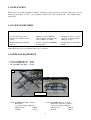
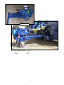
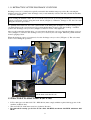
Tajfun Planina, proizvodnja strojev d.o.o.
Planina 41 a, 3225 Planina pri Sevnici, Slovenija
Tel.: +386 (0)3 746 44 20, Fax.: +386 (0)3 5791 016
E-mail: [email protected], http://www.tajfun.com
OPERATING INSTRUCTIONS
FIREWOOD PROCESSOR
RCA 380
:
RCA 380 E
Ver.: 2.2
05/2006-ENG
Please carefully read the operating instructions before using the machine!
1
TABLE OF CONTENTS
Chapter:
1
Page:
GENERAL
3
1.1
MANUFACTURER’S ADDRESS
3
1.2
APPLICATION
4
1.3
SCOPE OF DELIVERY
4
1.4
OPTIONAL EQUIPMENT
4
1.5
TECHNICAL DATA
6
1.5.1
6
SPECIFICATION PLATE
2
SAFETY INSTRUCTIONS
7
3
MACHINE SETUP AND OPERATION
7
3.1
3.1.1
DISCHARGE CONVEYOR ASSEMBLY
8
RETRACTION OF DISCHARGE CONVEYOR
9
3.2
TRACTOR PTO SHAFT DRIVE (RCA 380)
9
3.3
STARTING UP
10
3.4
TRANSPORT POSITION OF THE MACHINE
11
4
OPERATING THE FIREWOOD PROCESSOR
11
4.1
NOISE
11
4.2
LOG FEEDING
11
4.3
SAWING
13
4.3.1
4.4
13
ADJUSTING THE WOOD LENGTH
SPLITTING
13
4.4.1
ADJUSTING THE HEIGHT OF THE SPLITTING WEDGE
14
4.4.2
MACHINE COVER WITH SAFETY SWITCH
14
4.4.3
»START-STOP« SWITCH (RCA 380 E)
15
4.4.4
MAIN SWITCH (RCA 380 E)
15
4.5
5
DISCHARGE CONVEYOR
15
MAINTENANCE AND REPAIR
16
5.1
CHAIN REPLACEMENT
16
5.2
CHAIN TENSIONING
17
5.3
SPLITTING WEDGE REPLACEMENT
17
5.4
HYDRAULIC SYSTEM OIL CHANGE
17
5.5
OIL FILTER MAINTENANCE
18
5.6
LUBRICATION OF THE ANGLE REDUCTION GEAR (RCA 380)
18
5.7
CHAIN LUBRICATION
17
5.8
TROUBLESHOOTING
19
5.9
MAINTENANCE PLAN
20
5.10
CUTTING CHAIN BELT REPLACEMENT
22
5.10.1
BELT TENSIONING
23
5.11
INDICATIONS OF IMPROPER USE
24
5.12
SUPPLIES
24
5.13
SPARE PARTS ORDERING
24
WARRANTY SHEET
28
2
1 GENERAL
Dear Customer,
By purchasing our firewood processor you obtained the equipment which will provide you with great help in
your work. To make operating the machine as safe and pleasant as possible, please carefully read this operating instructions and follow the safety and maintenance directives.
We would like to thank you for your trust and wish you great satisfaction in your work.
1
C
E
D
K
R
T
F
G
H
B
J
L
A
S
RCA 380
P
RCA 380 E
A
Feed Conveyor
H
Sawbar activation Handle
B
Machine Cover with Safety Switch
J
Discharge Conveyor
C
Splitting Cylinders Control Handle
K
Discharge Conveyor’s speed Regulator
D
Handle for regulation of Feed Conveyor’s turning
direction
L
Splitting Wedge Handle
E
Log Loader Control Handle
P
Retaining Handle
F
Low pressure Gauge
R
Main Switch (RCA 380 E)
G
High pressure Gauge – Splitting
S
»Start –Stop« Switch (RCA 380 E)
T
Discharge Conveyor Valve (Check-choke valve)
1.1 MANUFACTURER’S ADDRESS
Tajfun Planina, d.o.o., Planina 41a, 3225 Planina pri Sevnici, Slovenija
Tel.: +386 (0)3 746 44 20, Fax.: +386 (0)3 5791 016, E-mail: [email protected], http://www.tajfun.com
3
1.2 APPLICATION
Firewood processor (RCA 380, RCA 380 E) is a machine used for preparation of firewood. The processor can
handle logs from 10 to 38 cm (4 – 15”) in diameter, which can be cut to 25-50 cm (10” – 20”) length and thereafter split.
1.3 SCOPE OF DELIVERY
• RCA-380 / RCA 380 E
• Discharge Conveyor
•
Operating Instructions
• Log Loader Control Valve –
• Chain 3/8" Oregon MULTI-
•
Discharge Conveyor’s speed
regulator – integrated in Discharge Conveyor
• Manual Winch Operating Ins-
• Sawbar: Oregon 178SLHD009
•
Electric Motor 11 kW (RCA
380 E)
integrated in machine control
panel
tructions
CUT ; Number of driving teeth
= 64, b= 0.058” (1.5 mm)
or compatible
Chain lubrication oil is not included in the scope of delivery.
1.4 OPTIONAL EQUIPMENT
• LOG LOADER DM 1501 – Tajfun
• LOG LOADER DM 1511 – Tajfun
• EL. POWER UNIT EP 11 – Tajfun
2
DM 1511
LOG LOADER DM 1501 – Tajfun
Retractable
Log loader length: 1500 mm
Lifting power:
4500 N
Weight:
125 kg
LOG LOADER DM 1511 – Tajfun
Retractable, with drive cylinders
Log loader length: 1840 mm
Lifting power:
4500 N
Weight:
160 kg
4
EP 11
ELECTRIC POWER UNIT EP 11 – Tajfun
Motor Power:
11 kW
Weight:
197 kg
5
1.5 TECHNICAL DATA
Length of Cut Log
25 – 50 cm (10" - 20")
Diameter of Log
10 – 38 cm (4 – 15")
Sawbar
Oregon 17", b=0,058" (1,5 mm)
Chain
3/8", 64 driving teeth , b=0,058" (1,5 mm)
Splitting Power
150 kN (≈15T)
Width
1290 mm (50,8")
Length
2350 mm (92,5")
Height
2360 mm (92,9")
Required Tractor Power (RCA 380)
30 kW (40 HP)
Electric Drive (RCA 380 E)
Electric Motor
U: 400V/50Hz P1: 11 kW, n=2910 min-1, IP 55
[400 – 430] min-1 (RPM)
Tractor P.T.O. Shaft Speed ( RCA 380)
Maximum pressure
250 bar
Oil Reservoir Volume
100 l (25 gal)
Chain Lubrication Oil Reservoir Volume
8 l (2 gal)
Operating Noise (Max.)
RCA 380: 92 dB (A) / RCA 380 E: 96 dB (A)
Weight
RCA 380: 900 kg (1985 ls)
RCA 380 E: 1100 kg (2426 ls)
Discharge Conveyor
Conveyor Length
4000 mm (13’)
Conveyor Belt Width
430 mm (17,5")
Maximum Speed
60 cm/s (24")
Weight
130 kg (286 ls)
1.5.1 SPECIFICATION PLATE
Serial number
Year of Manufacture
6
2 SAFETY INSTRUCTIONS
• Machine operation and maintenance is allowed to qualified persons older then 18 years of age, only!
• Before starting the work, the machine must be placed in a stable position,!
• Use only P.T.O. shafts of appropriate strength (min. 25 kW), with undamaged outer plastic protective
cover (RCA 380)!
• Never use damaged, cracked or deformed cutting chains!
• Always wear personal protective equipment (safety glasses, hearing protectors, gloves and forestry
boots)!
• When troubleshooting, replacing the chain or any service procedure, always disengage P.T.O. shaft and
•
•
•
•
•
•
•
•
•
•
shut down the tractor (RCA 380) or unplug the power cord from the electrical outlet (RCA 380 E)!
Do not wear loose clothes!
Keep the working environment clean and tidy!
Always use caution when operating the machine! Rotating chain can cause serious injuries in case of
incorrect use of the machine.
Never leave the machine running without supervision!
Do not reach into the working area, while the machine is in operation!
Before removing a wedged piece of wood, shut down the machine drive (RCA 380) or turn off the machine using »START-STOP« Switch (RCA 380 E)!
When transporting the machine on public roads it is necessary to install lights on the read end of the
machine!
For your own safety use only original spare parts and accessories which are approved by the manufacturer!
The machine must be grounded according to regulations (RCA 380 E)!
Damaged power cord or plug must be replaced immediately (RCA 380 E)!
3 MACHINE SETUP AND OPERATION
RCA 380 :
• Mount the firewood processor to the three-point tractor system using bolts. Lower tractor connecting han-
dles must be fixed with tensioning screws, so the machine cannot move transversely. When transporting
the machine, consider the weight of the whole machine (Chapter 1.5).
• Connect the P.T.O. shaft to the cardan shaft and secure it using the safety chain.
Before the first installation also check the P.T.O. shaft length.
Check the P.T.O. shaft length by raising and lowering the machine to determine the position with the
shortest distance among connecting shafts. Tubes should be in this position, when the P.T.O. shaft is
connected, app. 20 mm shorter.
In case the P.T.O. shaft is too long, it must be shortened:
•
Saw of steel and plastic tubes on both ends to the same length. Afterwards file down, clean and grease
the edges.
P.T.O. shaft must be connected to the machine as perpendicular as possible! Therefore, it is recommended the
machine is connected to the three point tractor system, during the operation.
7
RCA 380 E :
Connect the RCA 380 E to the thee-phase electric
power source:
• Nominal voltage: 400 V / 50 Hz
• Minimum Power Cable Size: 4 mm²
• Plug: 32A-CCE 3P+N+E 400V
• Nominal Current of the Main Fuses: 32 A
• Connection Power: 21,2 kW
I
Warning!
Before completing the connection of the machine
it is necessary to check the rotating direction of
the cutting chain and/or electric motor. Wrong
rotating direction can cause damages to the oil
pump.
II
Change the rotating direction of the electric
motor by inverting the poles on the plug.
3.1 DISCHARGE CONVEYOR ASSEMBLY (in case of separate delivery)
Hydraulically driven discharge conveyor is also a component part of the firewood processor.
• Place the discharge conveyor on the ground and move it closer to connecting spot
• Slide the discharge conveyor on the supporting forks and secure it with two screws (1– Figure:3)
• Fasten the lifting package by fixing rope pulleys to their position (2-Figure: 4).
• Use the hand winch (3-Figure: 3) to lift the discharge conveyor slightly above the desired height and
attach the carrying chain (4-Figure: 3).
• Loosen the wire rope, so that the weight of discharge conveyor is distributed between the wire rope and
carrying chain (4-Figure:3)
• Connect the hydraulic connectors (a & b)
3
a
3
a
b
b
1
4
8
3.1.1 RETRACTION OF THE DISCHARGE CONVEYOR
Discharge conveyor is usually telescopically retracted in the machine transport position. By activating the
machine, telescopic cylinder of the discharge conveyor automatically activates and fully extends the machine,
so the belt is tensioned.
Before starting the machine, make sure to loosen the conveyor belt, by moving the Discharge Conveyor from
vertical to horizontal position using the hand winch (3-Figure:3). Otherwise damages to the belt can occur
during the extension procedure!
To optimally tension the belt, move the control handle of the lifting table (E-Figure: 1) to the lowering position, which increases the system pressure. To position the Discharge Conveyor into the working – extended
position, the discharge conveyor valve (T:Figure:1) must be closed – fully tightened.
After you disconnect the machine drive, you can retract the discharge conveyor. Open the discharge conveyor
valve (T-Figure: 1) and leave the discharge conveyor to retract by its own weight. Therefore put the machine
in more upright position.
When the discharge conveyor is retracted, close the discharge conveyor valve (T-Figure: 4). The valve must
be also closed during the operation.
4
2
t
T
Ensure the clearance “t” between the nut
and the hand winch handle axis.
3.2 TRACTOR PTO SHAFT DRIVE (RCA 380):
•
•
•
P.T.O. shaft (grooved shaft 13/8!" Z6 – DIN 9611A) must comply with the required driving power of the
machine (technical data).
The tractor P.T.O. shaft must rotate in a clockwise direction.
Recommended rotating speed of the P.T.O. shaft: 420 RPM; maximum: 430 RPM, minimum: 400
RPM
9
3.3 STARTING UP:
Before each machine startup, it is necessary to check the chain tension and readjust it if necessary!
A too loose chain can induce vibrations, which unfavorably affect the drive belt’s operation. Increased vibrations can also cause damages to the drive belt. A new cutting chain needs to be retensioned after approx. half an
hour of use. Please check.
Remove all wood remains and other particles from the splitting chute, before starting the machine!
Check the oil levels of the hydraulic system and cutting chain lubrication system, before starting the machine!
Before starting the machine, make sure to loosen the conveyor belt, by moving the Discharge Conveyor from
vertical to horizontal position using the hand winch (3-Figure:3). Otherwise damages to the belt can occur
during the extension procedure!
RCA 380 :
•
•
•
•
•
•
Examine the machine and equipment for faults and check the chain lubrication
Place the tractor manual throttle handle in lowest position.
Lift the machine cover (B-Figure: 1a) to activate the safety switch and disengage all major machine functions.
Slowly engage the P.T.O. shaft drive and start the machine.
Set the required rotating speed of P.T.O. shaft (420 RPM), using the manual throttle handle.
Lower the machine cover.
RCA 380 E:
•
•
•
•
•
•
Examine the machine and equipment for faults and check the chain lubrication
Plug the machine to electric power source
Turn on the Main Switch (R-Figure: 1)
Lift the machine cover (B-Figure: 1) to activate the safety switch and allow easier starting of the electric
motor
Push the “Start-Stop” switch (green button) (S-Figure:1) and immediately check the rotating direction
of the cutting chain: in case of wrong cutting chain direction, immediately stop the drive (push the red
button on the “Start-Stop” switch and change the rotating direction of the electric motor (Chapter: 3.)
Lower the machine cover
10
3.4 TRANSPORT POSITION OF THE MACHINE
The maximum allowable speed of the tractor
when transporting the machine on the rut or offroad is 10 km/h (12 mph) and 40 km/h (25 mph),
when the tractor is driven on the asphalt roads!
5a
5b
Driving at
unsuitable
speeds for the
road conditions can cause
damages to
the machine
or the tractor.
4 OPERATING THE FIREWOOD PROCESSOR
The machine must be operated by one person only. Please ensure that there is nobody else in the near
vicinity of the machine working area.
4.1 NOISE
Machine operator is exposed to the following noise levels, during the machine operation (measured near the
ear of the machine operator):
RCA 380
RCA 380 E
Idling mode:
87 dB (A)
88 dB (A)
Operation mode:
92 dB (A)
96 dB (A)
Therefore, it is mandatory to wear hearing protectors while operating the machine.
4.2 LOG FEEDING
The in-feed conveyor must be placed in a horizontal working position before operation of the machine:
Pull out the safety pin (10-Figure:6)
Remove the support limiter (12-Figure:6)
Lower the in-feed conveyor (A-Figure:6) in horizontal position and support it using the supporting leg
(11-Figure:6)
• Set the supporting leg so that the upper rod on the conveyor belt in the middle of the feed conveyor is
slightly elevated above the table (already factory set)..
Activate the feeding by pushing the sawbar activation handle (H-Figure: 1) from the upper position (neutral
position) forward - away from yourself; you can stop it at any time (when the log reaches length limiter), by
returning the handle to the neutral position.
In case you don’t stop the feeding after the log reaches the length limiter, you can damage the in-feed
conveyor belt.
The in-feed conveyor can be additionally operated with the handle for setting its rotating direction (D-Figure1). Using this handle, the conveyor belt can be activated in either direction.
•
•
•
11
10
6
12
A
11
7
H
P
12
4.3 SAWING
The barsaw is always operating.
The sawbar movement is performed using the sawbar activation handle (H-Figure: 7), during which the sawed
log must be held using the retaining handle (P- Figure: 7). When the sawing begins, the trapdoor (13-Figure:8)
moves away automatically, so the log can fall freely into a splitting chute after the cut.
Adjust the sawbar moving speed according to the hardness of the wood. Finish the cut (app. last 20 mm - last
1 in ) with rapid downward movement of the sawbar activation handle, to make the cut log fall into the chute
correctly.
When cutting hard wood, the cut log can fall into the chute and rebound in the air - and splitting cylinder can
grab it sideways*, which can cause the jam and even damage to the machine. To avoid this, hold the sawbar
activation handle after the cut in lower position, to allow the cut log to correctly position itself in the chute.
Only then lift the sawbar activation handle to activate one of the two splitting cylinders.
*… in this case quickly switch the cylinders or open the machine cover, to stop the splitting cylinder
and reposition the cut log.
The force on the sawbar activation handle should not exceed 100N. Greater force can cause increased
vibrations of the belt, which may result in damage to the belt. Check the tension of the belt (Chapter:
5.9).
4.3.1 ADJUSTING THE WOOD LENGTH
The length of the firewood is set by adjusting the position of the length limiter (15-Figure:8) , which is fixed
in the required position using the fixing pin (14-Figure:8).
8
14
13
15
4.4 SPLITTING
Splitting is performed by a splitting cylinder that pushes the log towards a splitting wedge. The splitting speed
depends on the wood resistance and changes during splitting. Since the splitting speed is inversely proportional with the splitting force, the splitting cylinder enables greater splitting force at a lower speed and smaller
splitting force at a greater splitting speed. The splitting cylinder automatically selects the necessary speed or
splitting force, which results in greater energy efficiency.
The activation of splitting cylinder is performed by lifting the sawbar activation handle (H-Figure 1), after the
log has been cut or using the cylinder operating handle (C-Figure:9). Cylinder operating handle (C-Figure:9)
can also be used at any time, to move the Cylinder Piston to the starting position, which is sometimes required
in practice to prevent jamming during the splitting phase.
13
9
C
S
B
B
4.4.1 ADJUSTING THE HEIGHT OF THE SPLITTING WEDGE
10
L
By using a splitting wedge handle (L-Figure: 10), the splitting wedge
can be gradually lifted or lowered depending on the diameter of the logs
- so the logs are split in center.
Splitting wedge adjustment can be performed most easily when the splitting chute is empty or at the point when the splitting cylinder start to
move.
Lifting mechanism of the splitting wedge also allows partial height
movements of the splitting wedge during the splitting phase. In case the
wood gets stuck under the splitting wedge it must be removed to prevent
damage to the lifting mechanism of the splitting wedge (Refer to chapter
5.11, indications of overload…).
4.4.2 MACHINE COVER WITH SAFETY SWITCH
In case of eventual problems during the splitting phase, or in case the log is wrongly positioned in the splitting
chute, the splitting process must be stopped immediately. In this case it may be also necessary to switch the
cylinder, so the splitting cylinder which pushes towards the splitting wedge, moves back (4.4).
Machine cover (B-Figure: 11) is linked to the safety switch, which disengages all major machine functions
when the machine cover is lifted: in-feed and discharge conveyors stop, splitting cylinder stop and sawbar is
withdrawn into the saw shield. Lifting the machine cover therefore acts also as a main safety switch.
The log can be reached by hand only when the machine cover is opened and machine is stopped. Sawing and
splitting cannot continue until the machine cover is closed and safety switch disengaged.
14
11
B
STOP
4.4.3 “START-STOP” SWITCH (RCA 380 E)
Electrical system of the wood processor RCA 380 E includes, besides the main switch, also the “Start-Stop”
switch (S-Figure: 1). The “Start-Stop” switch is used to turn ON/OFF the electric driving motor, which
powers the cutting chain and whole hydraulic system. Using the red button of the “Start-Stop” switch you can
completely stop the operation of the machine.
Before staring the machine or pushing the “start-stop” switch it is recommended to lift the machine cover, to
allow easier starting of the electric motor (Refer to chapter 3.3).
4.4.4 MAIN SWITCH (RCA 380 E)
The wood processor’s main switch (R-Figure: 1b) shuts down the main power supply. Use the main switch
when stopping the work for longer periods or leaving the work place. Unauthorized access to the power switch
can be prevented by installing the padlock.
4.5 DISCHARGE CONVEYOR
Lifting and lowering of the discharge
conveyor is performed with the hand
winch handle (23-Figure: 12). When
the desired position is reached, secure it with the chain, so that the weight
of discharge conveyor is distributed
between the wire rope and the
carrying chain.
(24 – Figure: 12).
12
23
K
24
When using and maintaining the
hand winch, follow the enclosed
manufacturer’s instructions.
The speed of the discharge conveyor
can be adjusted using the speed regulator of the discharge conveyor
(K-Figure: 12).
15
5 MAINTENANCE AND REPAIR
Regular machine maintenance ensures reliable operation and long lifetime of the machine
5.1 CUTTING CHAIN REPLACEMENT
Before replacing the chain, you must disconnect the machine drive (RCA 380) or unplug the power cord
from the electrical outlet (RCA 380 E)!
Disconnect the P.T.O. shaft or unplug the power cord from the electrical outlet.
Turn the handle (28-Figure:13) 90 degrees on the sawbar activation handle.
Unscrew the screw (29-Figure:13) and move the saw shield (30- Figure:14) in the forward position.
Loosen the cutting chain tensioning screws (33-Figure:15)
Unscrew both nuts (34- Figure: 15) on the fixing plate (35- Figure: 15) until you can move the sawbar
away from the tensioner.
• Remove the worn cutting chain and replace it with new well-sharpened chain.
• Make sure the cutting teeth are turned in the right direction – the cutting edge on the top of the sawbar
must face the machine controls.
• Replace the cutting chain in a reverse order and don’t forget to tension it afterwards.
•
•
•
•
•
A new cutting chain must be run-in; 2 to 3 minutes. The cutting chain tension must be rechecked immediately
afterwards. (Refer to chapter 5.2)
Do not install a new cutting chain on a worn out sprocket. Replace the sprocket after second replacement of
the worn out chain at the latest.
13
14
28
30
29
15
33
34
35
16
5.2 CUTTING CHAIN TENSIONING
•
•
•
Loosen both nuts (34-Figure: 15) on the fixing plate (35-Figure: 15)
Tighten the tensioning screw (33-Figure: 15) until the chain in tensioned correctly*
Tighten both nuts (34-Figure: 15) on the fixing plate (35-Figure: 15)
*The cutting chain is tensioned correctly when it clings to the lower side of the sawbar when cold and can be
still lifted on the upper side of the sawbar (approximately in the middle), three or four times the height of the
driving teeth.
Always wear gloves when checking the chain tension to avoid cutting your fingers on the sharp chain!
5.3 CHANGING THE SPLITTING WEDGE
• Remove all firewood and wood remains from the splitting wedge area (splitting chute and under the mac•
•
•
•
•
hine).
Activate the splitting cylinder and open machine cover when the cylinder reaches the middle position, to
make enough room for splitting wedge replacement.
Put the handle of the splitting wedge (L-Figure: 16) in the right position, to lower the splitting wedge
completely.
Remove the splitting wedge from its mount and replace it with a new wedge (39-Figure: 17)
Close the machine cover.
Set the desired splitting wedge height.
17
16
L
39
5.4 HYDRAULIC SYSTEM OIL CHANGE
Important:
To prevent pollution of the environment, dispose of used oil properly!
• Perform the first oil change after 5000 hours of operation. Afterwards change the oil every 2 years
• The oil drain plug is located on the lower side of the tank.
• Hydraulic system oil quantity: 100 l. / 25 gallons
17
Hydraulic oil – suitable brands: (Viscosity: 46 mm2/s at 40oC)
Manufacturer’s:
Substitute oils:
Castrol Hyspin AVH 46
Mobil DTE 16
Renolin B 46 - HVI
Shell TELLUS T46
BIPI Energol SFA 46
SETRAL Poclain
5.5 OIL FILTER MAINTENANCE
• Check and/or clean the oil filter when the first oil change is performed. Presence of small aluminum partic-
les, caused by running-in of the pump is expected.
• Clean the filter insert using gasoline. Work in open areas and take necessary precautions to prevent fire.
Using an air compressor, blow the filter insert from inside out.
• Filter insert must be replaced only if the filter gets mechanically damaged.
• Bad filter permeability is shown on the filter gauge – if the gauge indicator is in the red zone when oil is
heated to operating temperature. Change the oil filter
5.6 LUBRICATION OF THE ANGLE MULTIPLICATION GEAR (RCA 380)
• Oil quantity and grade: 1.2 l (0,32 gallon), SAE 75 (Renolin CLP 100 DIN 51 517/13)
• Replace the oil when changing the reduction gear bearings.
5.7 CUTTING CHAIN LUBRICATION
Never operate the machine without lubricating the chain first!
Chain lubrication oil quantity: 8 L
Approximate oil consumption: (0.6-1.0) L/h
Quality chain lubrication oils with viscosity grade of 95 mm2/s at 40ºC are recommended.
18
Never use used oils!
The flow of the cutting chain lubrication oil can be regulated depending on
the oil quality, using a regulation screw (Figure: 18). It is factory set to
maximum!
18
5.8 TROUBLESHOOTING
PROBLEM
POSSIBLE CAUSES
The machine does not react to movements
of the sawbar activation handle
SOLUTION
Check the machine drive (P.T.O. shaft or
electric motor must be connected and in
operation, otherwise the pump and
chainsaw drive do not work)
Check the level of the oil in the tank
Damaged control mechanism
Repair or replace the control mechanism ⊗
Electric motor does not start or it often
shuts down (RCA 380 E)
Damages to power cables or blown fuses
Check the power cables, install the approp-
Motor protection is shutting the motor
down.
Power cable size is not appropriate, the
machine is overloaded
Hydraulic oil is overheating
Not enough oil in the reservoir
Check the oil level and add more if
necessary.
Worn-out hydraulic oil
Change the hydraulic system oil.
Clogged oil filter
Clean the oil filter. (5.5)
Clogged hydraulic pipes
Check the hydraulic pipes and clean them if
necessary.
Splitting cylinder did not reach the final
position.
Reverse the cylinders, clean the splitting
chute
High Outside Temperature
Install the oil cooler
Hydraulic oil is overheating
Refer to “ Hydraulic oil is overheating“
Not enough oil in the reservoir
Check the oil level and add more if
The machine is overloaded
Remove the overloading causes
The chain is dull
Sharpen or replace the chain
The chain is not properly tensioned
Tension the chain
The chain is covered with resin
Clean the chain using the solvent (i.e. Nitro-Solvent) or replace the chain
Revolution speed of the tractor is exceeded
(RCA 380)
Consider the recommended revolution
speed.
Clogged filter
Clean the filter
Not enough oil in the reduction gear
Check the oil level and add more if
necessary.
Machine is loosing power
Excessive power consumption during
sawing
Louder operation of the machine
The machine is not connected to the tractor Connect the machine to the tractor or posi– only P.T.O. shaft is connected (RCA 380) tion the tractor perpendicular to machine
Hydraulic hoses are overheating
Hydraulic cylinder is leaking
P.T.O. shaft is not lubricated
Lubricate P.T.O. shaft appropriately
Not enough oil in the hydraulic system
Check the oil level and add more if
necessary.
Worn-out hydraulic oil
Replace the hydraulic system oil. (**)
Seals are worn-out
Replace worn-out seals.
Damaged piston-rod
Replace the cylinder
In-feed conveyor is slipping or not opera- Conveyor belt is not tensioned enough
ting
Not enough oil in the hydraulic system
19
Tension the conveyor belt
Check the oil level and add more if
necessary.
PROBLEM
POSSIBLE CAUSES
In-feed conveyor is not generating eno- Conveyor belt is not tensioned enough
ugh pull, although low pressure gauge
Incorrect installation of the conveyor
shows 90 bars during its operation.
belt
The log too heavy or jammed
The chain is not lubricating
Discharge conveyor is not operating
SOLUTION
Tension the in-feed conveyor belt
Check the placement of the supporting
foot (Chapter.:4-2)
Position or cut the log – shorten the log
The machine ran out of chain lubricati- Add chain lubrication oil
on oil
Lubrication system is clogged or
damaged
Check the lubrication system
Conveyor belt is not tensioned enough
Tension the conveyor belt
Not enough oil in the hydraulic system Check the oil level and add more if
necessary
Speed regulator is fully screwed down
Set the speed regulator appropriately
Stuck wood is preventing the conveyor Clean the conveyor belt area – stop the
belt from moving.
machine during cleaning procedure.
Torn cutting chain drive belt
Inappropriate rotating speed of the
P.T.O. shaft + worn cutting chain
Replace the belt (5.10), replace the
cutting chain (5.1). Increase the rotating speed of the P.T.O. shaft (3.2).
Cutting chain is not properly tensioned Replace the belt (5.10), tension the
cutting chain properly (5.2)
Belt is not properly tensioned
Replace the belt (5.10)
Excessive force on the operating handle during cutting
Replace the belt (5.10), (4.3), check the
cutting chain and use lower force on
the operating handle.
⊗ More demanding procedures must be performed by a qualified technical service only.
(**) In worse operating conditions with high temperatures of the environment we recommend installation of oil cooler.
5.9 MAINTENANCE PLAN
The machine must be turne d off (the P.T.O. shaft must be disconnected from the tractor), while performing any
service and maintenance procedures!
WHAT?
WHEN?
HOW?
Check the tension of the cutting chain
Before each use
5.2.
Check the tension of the cutting chain
belt
Every 50 hours of operation
5.10.1
Tighten any loose bolts and nuts and
hydraulic connections
• After first hour of operation
• After every 100 hours of operation
Using appropriate tools
Check the oil level
(hydraulic & bar oil levels)
Before each use
visually
Hydraulic system oil change
First after 5000 hours of operation,
afterwards once every two years
5.4
Cleaning the oil filter
During the oil change or in case the
gauge indicator is in the red zone
Clean the filter with gasoline and blow
it with compressed air from inside out.
Multiplication gear oil change
(RCA 380)
When changing the multiplication gear Drain the oil in the appropriate vessel
bearings.
from the lowest plug and replace the
plug. Fill the oil through the upper
plug.
Regularly remove all wood remains and sawdust from the splitting channel, under the conveyor belt, under
the lifting mechanism of the Splitting Wedge and under Sawbar Activation Handle!
20
c
19
d
b
a
WHAT?
WHEN?
HOW?
Lubrication Point: a, b, c
At least every 80 hours of operation
Lithium Grease
Lubrication Point: d
At least every 80 hours of operation
Lubricating Spray
Lubrication (Figure:19)
21
5.10 CUTTING CHAIN BELT REPLACEMENT
• Disconnect the machine from the drive or unplug the power cord from the electrical outlet
• Remove the drive protection (41 – Figure: 22), remove the housing cover (42 – Figure: 22), remove the
drive cover (43 – Figure: 22)
Remove the lubrication pump (44 – Figure: 22)
Loosen the belt tensioner (45- Figure: 22)
Remove the belt (46 – Figure:22) from the driven pulley (47 – Figure: 22)
Remove the old belt and clean the area
Install the new belt
Position the belt onto the pulleys.
Tension the belt and reinstall removed elements: lubrication pump (44 – Figure: 22), drive protection (41 –
Figure: 22), housing cover (42 – Figure:22), drive cover (43 – Figure: 22)
• After one hour test operation, recheck the tension of the belt (disconnect the machine from the drive). Perform additional tension controls every 50 hours of operation.
•
•
•
•
•
•
•
c
22
e
a
44
44
41
b
d
f
42
45
46
43
22
5.10.1 BELT TENSIONING
The machine must be stopped, during the operation!
Set the correct tension of the belt using the notch on the tension indicator. The notch must be aligned with the edge of the
spring guide. Set the tension of the belt as follows:
• Loosen the safety nut (47-Figure: 23)
• Screw or unscrew the spring guide, as appropriate (48-Figure: 23) and correctly align the notch
• Tighten the safety nut (47-Figure: 23)
23
48
47
23
5.11 INDICATIONS OF IMPROPER USE
Certain damages which occur before the end of the lifespan of exposed machine components may indicate
overloading or inappropriate handling of the machine. Manufacturer’s warranty does not cover damages of
this kind.
•
•
•
•
•
•
•
•
•
•
•
•
Torn or damaged in-feed or discharge conveyor belts
Torn cutting chain
Damaged chain guide (sawbar)
Damaged or bent framework, wedge or cylinder protection
Damaged or bent length limiter or trapdoor
Torn cutting chain drive belt
Damages to the operating handles
Damages to the framework due to unsuitable transport
Damaged hand winch on the conveyor
Damaged carrying chain carabiner
Damaged wedge holder
Damaged or broken splitting wedge
Important:
The machine is functionally and safety tested. To ensure flawless and safe operation it is necessary to use only
original spare parts in case of breakdown. The customer looses all claims of warranty if non-original spare
parts are used, if repairs are performed unprofessionally or by unqualified person or in case of any modifications to the machine.
5.12 SUPPLIES
The machine incorporates following parts, which have to be replaced by the customer as necessary. These
parts are not covered by the warranty period, which is defined in the warranty statement.
Cutting chain
Drive chainwheel
• Cutting chain guide (sawbar)
• Cutting chain drive belt
• Electric motor driven belt
• Conveyor wire rope
• In-feed conveyor belt
• Discharge conveyor belt
• Splitting wedge
• Oil
5.13 SPARE PARTS ORDERING
When ordering spare parts it is necessary to provide the following information:
Model and serial number of the machine; catalogue number, name and quantity of the spare part;
Exact address of the customer
The manufacturer warrants spare parts availability and service 10 years after the purchase of the machine
24
Tajfun Planina, proizvodnja strojev d.o.o.
Planina 41 a, 3225 Planina pri Sevnici, Slovenija
Tel.: +386 (0)3 746 44 20, Fax.: +386 (0)3 5791 016
E-mail: [email protected], http://www.tajfun.com
EC Declaration of Conformity
Manufacturer:
TAJFUN Planina, proizvodnja strojev d.o.o., Planina 41a, 3225 Planina pri Sevnici
declares with full responsibility that hereinafter mentioned product:
FIREWOOD PROCESSOR
RCA 380
covered by this declaration complies with the requirements of:
Directive 2006/42/EC
and is in compliance with harmonized standards:
EN ISO 4254-1:2009; EN ISO 12100:2010; EN ISO 13857:2008; EN 349:1993+A1:2008;
EN 609-1999+A2:2009; ISO 4413:2010
Authorized person for technical documentation:
Iztok Špan, Planina 41a, SI-3225 Planina pri Sevnici
Planina, 04. 10. 2012
Iztok Špan
General Manager
25
Tajfun Planina, proizvodnja strojev d.o.o.
Planina 41 a, 3225 Planina pri Sevnici, Slovenija
Tel.: +386 (0)3 746 44 20, Fax.: +386 (0)3 5791 016
E-mail: [email protected], http://www.tajfun.com
EC Declaration of Conformity
Manufacturer:
TAJFUN Planina, proizvodnja strojev d.o.o., Planina 41a, 3225 Planina pri Sevnici
declares with full responsibility that hereinafter mentioned product:
FIREWOOD PROCESSOR
RCA 380 E
covered by this declaration complies with the requirements of:
Directive 2006/42/EC
Directive 2004/108/EC
Directive 2006/95/EC
and is in compliance with harmonized standards:
EN ISO 4254-1:2009; EN ISO 12100:2010; EN ISO 13857:2008; EN 349:1993+A1:2008;
EN 609-1999+A2:2009; ISO 4413:2010
Authorized person for technical documentation:
Iztok Špan, Planina 41a, SI-3225 Planina pri Sevnici
Planina, 04. 10. 2012
Iztok Špan
General Manager
26
27
WARRANTY SHEET
We guaranty:
• that the product will operate fault free, if operated according to enclosed operating instructions;
• that we will repair any fault or defectiveness during the warranty period, within 45 days. In case the
product is not repaired within the mentioned term, we will replace it with a new product on
customer’s request.
The product is warranted 12 MONTHS from the day of purchase, which must be proved by the customer
with the certified warranty sheet (stamp of the shop, date of purchase and salesman’s signature, serial
number and year of manufacture).
Guarantee sheet is valid only if shown together with original invoice!
The warranty covers parts against defects in material and workmanship. In case of repairs performed by
unqualified person or if non-original spare parts were used, the customer looses all claims of warranty! Our
guaranty is void also in case of:
• Damages caused by not following these operating instructions
• Damages which are customer’s fault
• Damages resulting from improper use or overload and operation in unsuitable conditions
Type :
Serial number:
Year of manufacture:
DEALER:
Date:
Signature:
28