1
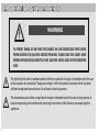
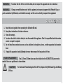
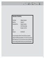
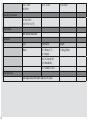
User Guide CONTENTS Important Safety Instructions ......................................................4 WARNING.......................................................................................4 Precautions ....................................................................................5 Fuse Positioning ............................................................................6 Regulatory Information ................................................................7 Getting Started ............................................................................10 Camera Setup Tips ......................................................................11 Hardware Connections ...............................................................12 BACK PANEL CONNECTIONS .................................................................................12 TYPICAL SETUP ............................................................................................................13 Controls Overview ......................................................................14 ON-SCREEN DISPLAY (OSD) ...................................................................................14 FRONT PANEL CONTROLS .......................................................................................15 On-Screen Display Controls .......................................................15 Front Panel Controls ...................................................................16 RESET . 16 OUTPUT .............................................................................................................................16 TRANSPARENCY Set these controls while viewing the matte or the composite...............16 SPILL Set these controls while viewing the composite ...........................................................17 CLEANUP Set this control while viewing the matte or composite.........................................17 FADE Set this control while viewing the composite. ...............................................................18 FREEZE ..............................................................................................................................18 Specifications and Technical Data .............................................18 DIP SWITCH SETTINGS .............................................................................................21 ADDITIONAL NOTES ....................................................................................................22 IMPORTANT SAFETY INSTRUCTIONS WARNING TO PREVENT SHOCK, DO NOT OPEN THE CABINET. NO USER SERVICEABLE PARTS INSIDE. REFER SERVICING TO QUALIFIED SERVICE PERSONNEL. PLEASE READ THIS USER’S GUIDE BEFORE OPERATING THE ULTIMATTE DV UNIT. SAVE THIS USER’S GUIDE FOR FUTURE REFERENCE. 4 The lightning flash with arrowhead symbol, within an equilateral triangle, is intended to alert the user to the presence of uninsulated “dangerous voltage” within the product’s enclosure that may be of sufficient magnitude to constitute a risk of electric shock to persons. The exclamation point within an equilateral triangle is intended to alert the user to the presence of important operating and maintenance (servicing) instructions in the literature accompanying the appliance. WARNING: To reduce the risk of fire or electric shock, do not expose this apparatus to rain or moisture Changes or modifications made to this equipment, not expressly approved by Ultimatte Corp, or parties authorized by Ultimatte, could void the warranty and the user’s authority to operate the equipment. WARNING: PRECAUTIONS 1. 2. 3. 4. Read this user’s guide before operating the Ultimatte DV unit. Keep these instructions for future reference. Heed all warnings. To reduce the risk of electric shock, do not disassemble this appliance. Take it to a qualified technician when service or repair is required. 5. Do not install near any heat sources such as radiators heat registers, stoves, or other apparatus that produce heat. 6. Unplug this apparatus during lightning storms or when unused for long periods of time. Two (2) 5mm X 20mm fuses must be installed on the ULTIMATTE DV power entry module. Fuses are positioned as shown below. FUSE REPLACEMENT: CAUTION: For Continued Protection Against Risk Of Fire, Replace Only With Same Type And Rating Of Fuse. 5 FUSE POSITIONING Second fuse on opposite side. 6 REGULATORY INFORMATION Declaration of Conformity Trade Name: Model No.: Responsible Party: USA Telephone: Ultimatte Corporation Ultimatte DV Ultimatte Corporation 20945 Plummer Street Chatsworth, CA 91311 818.993.8007 This device complies with Part 15 of the FCC Rules. Operation is subject to the following two conditions: (1) This device may not cause harmful interference, and (2) this device must accept any interference received, including interference that may cause undesired operation. 7 User Guide 9 GETTING STARTED 1 Gather or make a list of all the equipment you will be using with your Ultimatte DV. Keep in mind you will need a foreground input, a background input and a monitor (and recording device if desired) for the resulting output. 2 After selecting your equipment, use the Back Panel Connections and Typical Setup diagrams (in the next section - Hardware Connections) to ensure the connection types present on your equipment are compatible with the corresponding inputs and outputs on the Ultimatte DV. 3 Setup your bluescreen or greenscreen with some subject matter (a doll makes a good test subject while you are learning.) 4 Connect and power up your equipment. 5 Power up the Ultimatte DV. 6 Read the Controls Overview section that follows to get an overall feel for how the controls on the Ultimatte DV work. 7 Read the On-Screen Display Controls section for a more in-depth understanding of how to setup the operating environment options. 8 Read the Front Panel Controls section for a more in-depth understanding of how to refine your composite for the best possible results. 9 Practice! Experiment with the Ultimatte DV’s controls to get a better understanding of exactly what they do and when to use them. Experiment with your camera, lighting and background to get a better understanding of the pitfalls (and how to avoid them) of bluescreen/ greenscreen shots. 10 CAMERA SETUP TIPS When setting up your camcorder for an Ultimatte DV shoot: 1 All automatic features should be turned off. 2 Make sure to AWB (Auto White Balance) your camcorder before shooting for an Ultimatte DV. If you are using a Reflecmedia blue or green ring light, make sure the ring light is off before setting or adjusting white balance. 3 Below is a list of camcorder menu settings that should be adjusted for the ideal performance of the Ultimatte DV. Depending on your camcorder type, some of the controls may not be adjustable or may not appear on your camcorder menu. DETAIL LEVEL: ...................0 or -3 V DETAIL CORING: ............0 SKIN TONE DETAIL: ...........OFF V DETAIL FREQ: .................THIN MASTER PED: ...................0 GAMMA: ...........................NORM MATRIX: ............................NORM KNEE: ...............................MID or HIGH AUTO IRIS: ........................OFF COLOR TEMP: ...................0 ATW: .................................OFF MID GAIN: ........................0 db HIGH GAIN: .......................0 db AGC: .................................OFF 11 HARDWARE CONNECTIONS BACK PANEL CONNECTIONS standard S-Video connection Television System Selector RS232 Editor/Control port and Software Upgrade port ��������������������� ��� ����� ��� ����������������� ������� ����� ��������������� �������� ������������� ������� ����� �� ����� �� ������� �� ����� �� ������� BI-DIRECTIONAL OUTPUTS INPUTS INPUTS IEEE 1394 (400 Mbps) (4-pin) Input (FG or BG) or Output S-video and composite outputs simultaneously active. Background inputs selected via OSD (see page XX.) Foreground inputs selected via OSD (see page XX.) 12 standard composite connection (RCA/cinch type connector) USB 2.0 (Future use) AC Power Ground TYPICAL SETUP ��������������������� ��� ����� ��� ����������������� ������� ����� Real time output RECORDER (or computer) ��������������� �������� ������������� ������� ����� �� ������� �� ����� Real time view during shooting MONITOR/TV �� ������� �� ����� Background IN DVD PLAYER Foreground IN CAMCORDER 13 CONTROLS OVERVIEW All controls on Ultimatte DV can be adjusted by following the procedures as described below. ON-SCREEN DISPLAY (OSD) • Press the Menu button on the front panel. • An On-Screen Display (OSD) will be visible over the video output indicating the current settings: Ultimatte DV - Version 1.00.00.00 Backing Color FG Input BG Input Power Up Mode Settings Exit Cancel * Blue Green • Turn the large, rotary knob to navigate up or down the menu. • When the desired configuration menu is reached, press the Menu button to activate the submenu, and turn the knob to navigate up and down the submenu. • Press the Menu button to accept the selection and return to the previous menu. • Go to Exit to accept all chosen selections and exit the OSD by pressing the Menu button. • Go to Cancel and press the Menu button to exit the OSD without changing settings. 14 FRONT PANEL CONTROLS • Press the button for the desired control adjustment until the LED is lit. • Turn the Rotary Knob clockwise to increment the control amount or turn counter-clockwise to decrement the control amount. • Turn the knob slowly for fine adjustments. • Turn the knob quickly for coarse adjustments. • Position is indicated by the illuminated portion of the ring light. Minimum light indicates minimum control position and maximum light indicates maximum control position. • Press the button again until the LED is unlit to “lock” the control in place thereby avoiding accidental adjustments. ON-SCREEN DISPLAY CONTROLS • • • • Backing Color: Blue, Green FG Input: Turn the knob until the desired foreground input is selected (S-Video, Video, Digital(DV)). BG Input: Turn the knob until the desired background input is selected (S-Video, Video, Digital(DV)). Power Up Mode: Turn the knob to select Factory or User (if saved) power-up settings. If User is chosen, controls and inputs will be restored to the user saved settings (see Settings below) on power up. If Factory is chosen, controls will be restored to factory defaults and inputs will be restored to their state at last power down. • Settings: Turn the knob to select Save to save user defined defaults. Select Load to load previously saved user defined defaults. • Exit: Exits the main menu using the chosen settings. • Cancel: Exits the OSD menu with no change. Warning Video is always available on both the S-Video and Composite outputs. Video is only available on the Digital Video output if not chosen as an input in the configuration menu. If no video is seen through the Digital Video output, then it is most likely that Digital Video has been chosen as a foreground or background input. Temporarily use the S-Video or Composite output in order to ensure Digital Video is not selected for either FG Input or BG Input. 15 FRONT PANEL CONTROLS RESET Press the reset button to reset all controls to the factory default values. The LED will remain lit until all controls have been reset. The reset control will not affect the user-saved settings. If the reset LED flashes, the unit is requesting to re-sample screen values. This will typically occur when a change has been made to the foreground input or the backing color. Press the reset button. OUTPUT Press the output button, the LED will light. Turn the rotary knob to cycle through the available outputs as seen on the video monitor. The image displayed on the video monitor is exactly what will be output through the back panel output connectors: 1 2 3 4 5 6 7 8 9 Composite using free running video Composite using Freeze (background framestore) Composite with Test Signal #1 (Gray) Composite with Test Signal #2 (Bars) Composite with Test Signal #3 (Gradient) Background using Freeze Background (live video) Matte Foreground TRANSPARENCY Set these controls while viewing the matte or the composite. These controls are used to adjust the density or opacity of the foreground objects. The density of a foreground object is determined by its matte 16 (alpha) value. A completely opaque object’s matte will be white, a completely transparent object’s matte will be black, and a partially transparent object’s matte will be gray. To adjust this control, press the corresponding button until the LED is lit. Turn the rotary knob until the desired effect is reached. • Brights: Use this control to adjust density in bright foreground objects. Warning: Advancing this control too far can cause hard, dark edges around foreground subjects. To adjust this control, press the corresponding button until the LED is lit. Turn the rotary knob until the desired effect is reached. • Darks: Use this control to adjust density in black glossy or dark foreground objects. Warning: Advancing this control too far can cause hard, dark edges around foreground subjects. SPILL Set these controls while viewing the composite The Ultimatte algorithms will automatically suppress spill reflected from the backing onto foreground subject matter. These controls are used to suppress excessive spill. To adjust this control, press the corresponding button until the LED is lit. Turn the rotary knob until the desired effect is reached. • Color: Use this control to adjust the amount of spill in warm colored foreground objects. Used to reproduce pink, purple and magenta colors for bluescreen, or yellow and orange colors for greenscreen that changed through the spill suppression algorithms. To adjust this control, press the corresponding button until the LED is lit. Turn the rotary knob until the desired effect is reached. • Darks: Use this control to adjust the amount of spill on dark foreground objects. CLEANUP Set this control while viewing the matte or composite. To adjust this control, press the corresponding button until the LED is lit. Turn the rotary knob until the desired effect is reached. • Adjusting the cleanup control is used to adjust the black and gray areas of the matte channel. This will dramatically affect the nature of foreground objects' edges, the opacity of transparent objects, and the noise in the foreground image. Warning: Use this control sparingly as it WILL result in the loss of foreground detail. 17 FADE Set this control while viewing the composite. To adjust this control, press the corresponding button until the LED is lit. Turn the rotary knob until the desired effect is reached. • Adjusting the mix control will simulate the effect of a “fade” function. The final video will be a mix between composited image and the background. FREEZE • This control is used to store a single frame to be used as the background image in Ultimatte DV. A valid video signal must be connected to the background input as chosen through the configuration set-up. When the desired frame is seen on the video monitor, press the Freeze button until the LED is lit to alert Ultimatte DV to use the single frame (as opposed to the free running video connected to the back panel connector) as the background input. SPECIFICATIONS AND TECHNICAL DATA Video Standards: NTSC, PAL Analog Video Inputs: 18 Foreground: Signal Type: Connectors: Nominal Level: Impedance: S-Video 1 x S-Video (Y/C) 1 x Female 4-Pin Mini DIN Y of S-Video: 1 Vp-p C of S-Video: 0.3 Vp-p 75 Ohms Composite Video 1 x Encoded (Comp.) Video 1 x Female RCA Encoded (Comp.) Video: 1 Vp-p 75 Ohms Background: Signal Type: Connectors: Nominal Level: Impedance: S-Video 1 x S-Video (Y/C) 1 x Female 4-Pin Mini DIN Y of S-Video: 1 Vp-p C of S-Video: 0.3 Vp-p 75 Ohms Composite Video 1 x Encoded (Comp.) Video 1 x Female RCA Encoded (Comp.) Video: 1 Vp-p 75 Ohms Signal Type: Connectors: Nominal Level: Impedance: S-Video 1 x S-Video (Y/C) 1 x Female 4-Pin Mini DIN Y of S-Video: 1 Vp-p C of S-Video: 0.3 Vp-p 75 Ohms Composite Video 1 x Encoded (Comp.) Video 1 x Female RCA Encoded (Comp.) Video: 1 Vp-p 75 Ohms Signal Type: Connector: 1 x IEEE-1394 (Firewire) Interface IEEE-1394 4-Pin Signal Type: Connector: 115kbaud; 8 data bits; 1 stop bit; non-parity 1 x 9 Pin D-type, Female Signal Type: Connector: USB 2.0 1 x Mini USB Type B Voltage: Current: Analog Video Outputs: Digital Video Input/Output Selectable as Background or Foreground Input OR Output Control Interface: RS-232 USB Power: Fuse: 19 100 - 240V~ 50/60 Hz 0.15 - 0.10 A TO.5A 250V~ Type: Dimensions: Weight: Metal H = 45mm (1.7”) (1U Height) 2.04Kg (4.5lbs) Operating Temperature: 0°C to +50°C (+32°F to +112°F) Rack Mount: With optional Rack Shelf Enclosure: W = 212mm (8.35”) (0.5 Rack Width) D = 303mm (11.93”) Total Unit Delay Total signal delay from input to output is 192 µsecs. 20 DIP SWITCH SETTINGS Switch 1: Pedestal (black level) setting OFF = 0 IRE (Pedestal is not added (NTSC-J)) ON = 7.5 IRE (Pedestal is added to the output video (NTSC-M)) �� � � � � � � � � �� Switch 6: Flare Extension OFF = Normal ON = Flare suppression will start at a higher value. � � � � � � � � Switch 7: Matte Invert OFF = Subject is black, screen area is white ON = Subject is white, screen area is black Bottom view Switch 8: Output view text label setting A text label describing the current output view is normally displayed in the upper left corner of the screen when selecting different output views. The text is displayed for 2 seconds. OFF = Disable ON = Enable 21 ADDITIONAL NOTES • Any physical cable disconnect/reconnect requires a unit reset. • A gray output screen indicates that no foreground input is detected. This can happen when no foreground is connected or because the wrong foreground input is selected. 22 Ultimatte Corporation, 20945 Plummer Street, Chatsworth, CA 91311 USA Ph. 818/993-8007 Fax 818/993-3762 www.ultimatte.com 23