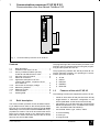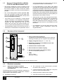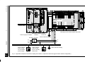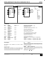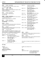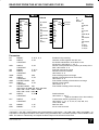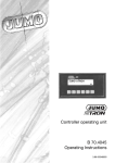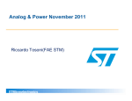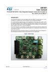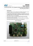
1
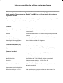
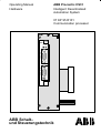
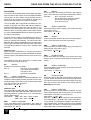
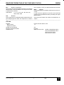
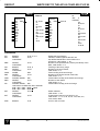
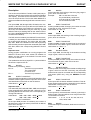
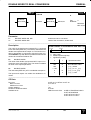
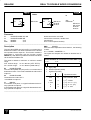
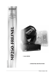
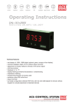
ABB Procontic Programming System
907 KP 95
CE definitions for the
communication module 07 KP 95
Order No.: GJP5 2066 00 R0102
Software Registration Form / Individual License
General License Conditions for the Supply of
Computer Software upon Payment of a Non–
Recurring License Fee (ALCN) / Floppy Disks
1
Hardware 07 KP 95
2
Installation
3
Examples
4
5
6
Connection element library
7
8
9
09.97
10
24 mm
907 KP 95 907 KP 95 907 KP 95 907 KP 95 907 KP 95 907 KP 95
CS31
CS31
CS31
CS31
CS31
CS31
GJP5 2066 00 GJP5 2066 00 GJP5 2066 00 GJP5 2066 00 GJP5 2066 00 GJP5 2066 00
ABB
ABB
ABB
ABB
ABB
ABB
Procontic
Procontic
Procontic
Procontic
Procontic
Procontic
Programming Programming Programming Programming Programming Programming
System
System
System
System
System
System
907 KP 95 907 KP 95 907 KP 95 907 KP 95 907 KP 95 907 KP 95
CS31
CS31
CS31
CS31
CS31
CS31
GJP5 2066 00 GJP5 2066 00 GJP5 2066 00 GJP5 2066 00 GJP5 2066 00 GJP5 2066 00
59 mm
ABB
ABB
ABB
ABB
ABB
ABB
Procontic
Procontic
Procontic
Procontic
Procontic
Procontic
Programming Programming Programming Programming Programming Programming
System
System
System
System
System
System
Notes on completing the software registration forms
Please complete the software registration forms in full and using a typewriter or in
block capitals. Please return the “Double” to ABB. Do not forget to sign the software
registration forms!
The software registration form should contain the following information in order to prevent difficulties or delays in provision of software updates for you:
Licensee
Name or company:
Full company name
Department/Contact person/Phone:
Name of department, name and telephone number of the
contact person
Address:
Street/road and number or P.O.Box,country code, postal code,
town/city
Date of delivery:
Already completed (if you do not have this information, please
(as defined in ALCN 4.1)
enter the date of receipt)
Name/legally binding signature:
Name in block capitals and signature
Customer Hardware (PC)
Hardware manufacturer:
Manufacturer of the PC used (e.g. Compaq)
Type:
Precise type designation of the PC used (e.g. 80486DX)
Software Product
Product name:
Designation of the software (e.g. 907 PC 331; already
completed)
Version:
Version number (already completed)
Identification No.:
Identification No. of the software (already completed)
Serial No.:
Diskette creation date (e.g. 12.92 = Dec. 92;
already completed)
ABB order No. or ABB office:
ABB order No. or ABB field office which supplied the software
(already completed)
New software version should be
offered according to ALCN 6.2:
State whether new software versions are to be offered in
accordance with ALCN 6.2
Specification in accordance with Item 5.2 ALCN
____________________________________________________________________________________________
General
The programming of the communication processor is carried out in the PLC program with a PC using the programming and test system 907 PC 331.
The programming software 907 KP 95 provides all connection elements necessary for operating the communication processor 07 KP 95:
●
AF100
●
DSPIN
●
DSPOUT
●
DWREAL
●
REALDW
The communication processor 07 KP 95 allows interfacing of ABB Procontic CS31 to the AF100 (Advant Fieldbus 100). The communication processor 07 KP 95 needs
additionally a communication interface CI520 and an appropriate bus modem. The 07 KP 95 contains the carrier
board for the CI520 (similar to the Submodule Carrier
Board with the Advant Controller 450, but the 07 KP 95
has only one slot for one CI520).
Survey of Advant Fieldbus (AF100),
07 KP 95 and ABB Procontic CS31
– The AF100 is a field bus, to which a maximum of 80
AF100 stations (nodes) can be connected. Each station can be a master or a slave. At least one master
must be connected to an AF100, several masters are
possible.
– The AF100 distinguishes between process data,
which are transmitted cyclically (Cyclic Data Packages) and messages (diagnosis data, events), which
are only transmitted if necessary.
–
The AF100 can be configured in single–channel
mode or redundant. In the redundant configuration,
the data are always sent via both busses. The data,
however, are only received from one bus. The
switch–over to the bus, from which the data is received, is performed automatically by the hardware.
–
The transmission medium for the AF100 can be a
twisted pair, a coaxial cable or an optical fiber. For the
connection between the coupler and the AF100 bus,
an appropriate modem must be selected.
–
For the transmission of cyclic data on the Advant
Controller side, the data base element DSP (Data Set
Peripheral) is available. Each DSP can contain up to
8 data elements (DATs) of the types boolean, integer,
long integer or real. In the data base element, the following is given: the number of DATs, the transmission
interval, the direction (sending or receiving DSP), the
identification and the station number.
–
Analog to that, on the CS31 side there are the function blocks DSPIN (receiving DSP) and DSPOUT
(sending DSP). As a maximum, a number of 475
DSPs with 8 DATs each can be configured. The max.
number of function blocks is 250 DSPINs and 249
DSPOUTs.
–
For initialization, the function block AF100 is available (station number, master/slave, AF100 bus
single/redundant).
Features of the unit 07 KP 95
The following functions are supported by the 07 KP 95:
–
master or slave at the AF100 (function block AF100)
–
single-channel or redundant configuration of the
AF100 (selectable via the function block AF100)
–
transmission of cyclic data using the function blocks
DSPIN and DSPOUT (max. 475 DSPs with 8 DATs,
max. 250 DSPIN and 249 DSPOUT)
–
service data: station, type, version, status
–
no event handling
–
no time-sync
–
no program-load
907 KP 95 / Issued: 09.97
Operating Manual
Hardware
ABB Procontic CS31
Intelligent Decentralized
Automation System
07 KP 95 R101
Communication processor
07KP95
CI
520
F R
X
8
C
H
1
X
9
C
H
2
ABB Schalt–
und Steuerungstechnik
Regulations
Concerning the Setting up of Installations
Apart from the basic ”Regulations for the Setting up of
Power Installations” DIN VDE* 0100 and for ”The Rating
of Creepage Distances and Clearances” DIN VDE 0110
Part 1 and Part 2 the regulations ”The Equipment of Power Installations with Electrical Components” DIN VDE
0160 in conjunction with DIN VDE 0660 Part 500 have to
be taken into due consideration.
Further attention has to be paid to DIN VDE 0113 Part 1
and Part 200 in case of the control of working and processing machines. If operating elements are to be
mounted near parts with dangerous contact voltage DIN
VDE 0106 Part 100 is additionally relevant.
If the protection against direct contact according to DIN
VDE 0160 is required, this has to be ensured by the user
(e.g. by incorporating the elements in a switch-gear cabinet). The devices are designed for pollution severity 2 in
accordance with DIN VDE 0110 Part 1. If higher pollution
is expected, the devices must be installed in appropriate
housings.
The user has to guarantee that the devices and the components belonging to them are mounted following these
regulations. For operating the machines and installations,
other national and international relevant regulations, concerning prevention of accidents and using technical working means, also have to be met.
The ABB Procontic devices are designed according to
IEC 1131 Part 2. Meeting this regulation, they are classified in overvoltage category II which is in conformance
with DIN VDE 0110 Part 2.
For the direct connection of ABB Procontic devices,
which are powered with or coupled to AC line voltages of
overvoltage category III, appropriate protection measures corresponding to overvoltage category II according
to IEC–Report 664/1980 and DIN VDE 0110 Part 1 are to
install.
Equivalent standards:
DIN VDE 0110 Part 1 ^= IEC 664
DIN VDE 0113 Part 1 ^= EN 60204 Part 1
DIN VDE 0660 Part 500 ^= EN 60439–1 ^= IEC 439–1
All rights reserved to change design, size, weight, etc.
*
VDE stands for ”Association of German Electrical Engineers”.
ABB Schalt– und Steuerungstechnik GmbH Heidelberg
1
Communication processor 07 KP 95 R101
Communication over the Advant Fieldbus 100
07KP95
CI520
F R
Fig. 1: Communication processor 07 KP 95 R101
The programming of the communication processor is carried out in the PLC program with a PC using the programming and test system 907 PC 331.
Contents
1.1
1.2
1.3
1.4
1.5
1.5.1
1.5.2
1.5.3
1.5.4
1.7
1.8
1.1
Brief description . . . . . . . . . . . . . . . . . . . . . . . . .
Features of the unit 07 KP 95 . . . . . . . . . . . . . .
Survey of Advant Fieldbus (AF100),
07 KP 95 and ABB Procontic CS31 . . . . . . . . .
Structure of the front panel . . . . . . . . . . . . . . . .
Electrical connection . . . . . . . . . . . . . . . . . . . . .
Application examples for AF100
coupling with modem, coupler 07 KP 95
and central unit . . . . . . . . . . . . . . . . . . . . . . . . . .
Connection of the supply voltage . . . . . . . . . . .
Networking interface . . . . . . . . . . . . . . . . . . . . . .
Measures for RFI . . . . . . . . . . . . . . . . . . . . . . . .
Technical data . . . . . . . . . . . . . . . . . . . . . . . . . . .
Ordering data . . . . . . . . . . . . . . . . . . . . . . . . . . . .
1
1
The programming software 907 KP 95 provides all connection elements necessary for operating the communication processor 07 KP 95:
2
2
2
●
●
●
2
5
5
5
6
8
●
●
1.2
Features of the unit 07 KP 95
The following functions are supported by the 07 KP 95:
Brief description
The communication processor 07 KP 95 allows interfacing of ABB Procontic CS31 to the AF100 (Advant Fieldbus 100). The communication processor 07 KP 95 needs
additionally a communication interface CI520 and an appropriate bus modem. The 07 KP 95 contains the carrier
board for the CI520 (similar to the Submodule Carrier
Board with the Advant Controller 450, but the 07 KP 95
has only one slot for one CI520).
07 KP 95 / Issued: 09.97
AF100
DSPIN
DSPOUT
DWREAL
REALDW
1
–
master or slave at the AF100 (function block AF100)
–
single-channel or redundant configuration of the
AF100 (selectable via the function block AF100)
–
transmission of cyclic data using the function blocks
DSPIN and DSPOUT (max. 475 DSPs with 8 DATs,
max. 250 DSPIN and 249 DSPOUT)
–
service data: station, type, version, status
–
no event handling
–
no time-sync
–
no program-load
07 KP 95
1.3
connection between the coupler and the AF100 bus,
an appropriate modem must be selected.
Survey of Advant Fieldbus (AF100),
07 KP 95 and ABB Procontic CS31
– The AF100 is a field bus, to which a maximum of 80
AF100 stations (nodes) can be connected. Each station can be a master or a slave. At least one master
must be connected to an AF100, several masters are
possible.
– The AF100 distinguishes between process data,
which are transmitted cyclically (Cyclic Data Packages) and messages (diagnosis data, events), which
are only transmitted if necessary.
–
–
For the transmission of cyclic data on the Advant
Controller side, the data base element DSP (Data Set
Peripheral) is available. Each DSP can contain up to
8 data elements (DATs) of the types boolean, integer,
long integer or real. In the data base element, the following is given: the number of DATs, the transmission
interval, the direction (sending or receiving DSP), the
identification and the station number.
–
Analog to that, on the CS31 side there are the function blocks DSPIN (receiving DSP) and DSPOUT
(sending DSP). As a maximum, a number of 475
DSPs with 8 DATs each can be configured. The max.
number of function blocks is 250 DSPINs and 249
DSPOUTs.
The AF100 can be configured in single–channel
mode or redundant. In the redundant configuration,
the data are always sent via both busses. The data,
however, are only received from one bus. The
switch–over to the bus, from which the data is received, is performed automatically by the hardware.
– For initialization, the function block AF100 is availThe transmission medium for the AF100 can be a
able (station number, master/slave, AF100 bus
twisted pair, a coaxial cable or an optical fiber. For the
single/redundant).
____________________________________________________________________________________________
–
1.4
Structure of the front panel
07KP95
1 Fixing screws above and below
for fastening on the earthed mounting surface. With this
fastening the earthing for the coupler is also performed.
CI520
4
F R
7
2 Supply voltage 24 V DC (red = L+, blue = M)
5
3 Networking interface for the ABB Procontic CS31
central unit (07 KT 93)
4 Communication interface CI520
6
5 Serial interface for modem coupling
3
6 Second serial interface for another modem
(in case of redundant operation)
7 LEDs
red (F) = Fault
green (R) = Ready
2
1
Fig. 2:
Communication processor 07 KP 95 with reference points
1.5
Electrical connection
1.5.1
Application examples for AF100
coupling with modem, coupler 07 KP 95
and central unit
The following figures show two application examples for
single–channel and redundant configuration. Attention
must be paid to the following in detail:
●
The earthing measures
07 KP 95
2
●
The connection of the communication processor
07 KP 95 to the modem(s).
●
Looping through the supply voltage (24 V DC) from
the 07 KT 93 to the 07 KP 95 R101
●
Earthing the switch cabinet mains sockets
●
Using the AF100 bus with coaxial cable
07 KP 95 / Issued: 09.97
07 KP 95 / Issued: 09.97
SB512
TC625
07KP95
CI520
F R
ABB Procontic CS31
07 KT 93
Coaxial cable
AF100
3
Mounting on the switch cabinet rear panel
Termination resistor earthed
Power supply for modem
Modem
230 VAC / 24 VDC
07 KP 95
L1
N
PE
Switch cabinet
mains socket
for the modem
power supply
+
–
Switch cabinet
mains socket
for PC, auxiliary
devices etc.
07 KP 95
Switch cabinet earthing
L+
M
Switch cabinet earthing
Fig. 3: Application example of an AF100 coupling with modem, coupler and central unit (typical switch cabinet configuration)
SB512
TC625
SB512
TC625
07KP95
CI520
F R
07 KP 95
ABB Procontic CS31
07 KT 93
AF100
AF100
4
Mounting on the switch cabinet rear panel
Power supply
for modem
Modem
Power supply
for modem
Modem
230 VAC / 24 VDC
L1
N
PE
07 KP 95 / Issued: 09.97
Switch cabinet
mains sockets
for modem
power supplies
+
–
Switch cabinet
mains socket
for PC, auxiliary
devices etc.
07 KP 95
Switch cabinet earthing
(Mounting surface)
L+
M
Switch cabinet earthing
Fig. 4: Application examole of an AF100 coupling with modems, coupler and central unit, redundant configuration (typical switch cabinet configuration)
1.5.2
Connection of the supply voltage
24 V DC
Mounting the communication processor at the networking interface
As shown in Fig. 3 and Fig. 4, the supply voltage for the 07
KP 95 is looped through from the CS31 central unit (red
wire = L+, blue wire = M).
1. Detach the cover on the central unit (e.g. 07 KT 93)
from the networking interface.
1.5.3
2. Plug the socket strip of the 40–pole ribbon cable secured to the 07 KP 95 R101 onto the networking connector of the CS31 central unit.
Networking interface
The networking interface, a special parallel interface, allows the 07 KP 95 communication processor to be connected to ABB Procontic CS31 central units 07 KT 93.
The housing of the communication processor is connected to the housing of the ABB Procontic central unit by
a snap–fit connection. The electrical connection is via a
40–pole ribbon cable with socket connector, soldered
onto the 07 KP 95 R101 side.
3. Slide both units together.
Note: Attachment and disconnection of units on the networking interface may only be performed when all supply
voltages are switched off.
–
Installation in a metallic switch–gear cabinet
–
Mains filters
07 KP 95 / Issued: 09.97
4. Slide the replacement cover provided with the
07 KP 95 unit with its cut-out onto the networking interface.
1.5.4
5
Measures for RFI (Radio Frequency Interference)
07 KP 95
1.7
Technical data
In general, the details in Section 1 ”System data and system structure” of volume 2 of the system description ”ABB
Procontic CS31” apply as technical data. Supplementary and deviating data is listed below.
1.7.1
General data
Number of parallel interfaces
1 networking interface for connecting to the
ABB Procontic CS31 central unit
1 interface for communication interface CI520
Note:
1.7.2
The communication interface CI520 must be ordered
separately and is not supplied together with the 07 KP 95
Supply voltage 07 KP 95 R101
Rated supply voltage
24 V DC
Power dissipation
typ. 6 W
max. current consumption
with rated voltage
with supply voltage 30 V
250 mA
200 mA
Protection against reversed terminal connection
yes
07 KP 95
6
07 KP 95 / Issued: 09.97
1.7.5
Mechanical data
Fastening on a mounting surface
by screws, distance 163 mm
height of mounting surface 180 mm
Width x height x depth
46 x 180 x 170 mm
Weight
1.2 kg
Dimensions for mounting
see following drawing
TC625
07KP95
CI520
178
Bore hole distance 163
F R
ABB Procontic CS31
07 KT 93
AF100
46
46
ca. 375 inclusive central unit
All dimensions in mm.
The device is 170 mm deep without CI520 inserted. The depth is 191 mm with CI520 inserted. There must be
enough space for interface connectors and cables.
Fig. 6: Outline dimensions of the communication processor 07 KP 95 R101, front view
1.7.6
Mounting hints
Mounting position
fastening on the switch cabinet rear panel
Cooling
The natural convection must not be hindered by
cable ducts or other material mounted in the switch
cabinet.
07 KP 95 / Issued: 09.97
7
07 KP 95
1.8
Ordering data
Communication processor 07 KP 95 R101
Order No. GJR5 2520 00 R0101
Scope of delivery
Communication processor 07 KP 95 R0101
Earthing instructions
Replacement cover for the networking interface
Further literature
System description ABB Procontic CS31, English
FPTN 4400 04 R2001
Operating manual 07 KR 91 / 07 KT 92 / 07 KT 93, Eng.
GATS 1316 23 R2001
Software
907 KP 95 R0102, Documentation, CE library
GJP5 2065 00 R0102 (German documentation)
GJP5 2066 00 R0102 (English documentation)
Additional components (see also Figures 3 and 4)
CI520
Communication interface
TC625
AF100 modem for coaxial cable (contains interface cable CI520 <–> TC625)
TC512
AF100 modem for twisted pair (contains interface cable CI520 <–> TC512)
SB512
Power supply unit for modem
These components can be ordered under the following address:
ABB Industrietechnik AG
Abteilung IND / OM
Dudenstraße 44–46
D–68167 Mannheim
Tel.: +49 621 381 1847 (Mr. Bräuler)
Additional literature
User’s Guide Advant Fieldbus 100
Document 3BSE 000 506R0101 (English)
Installation Rules
Document 3BSE 009 178R0001 (English)
07 KP 95
8
07 KP 95 / Issued: 09.97
Installation
ABB Procontic CS31
Intelligent Decentralized
Automation System
907 KP 95
CE definitions for the
communication processor
07 KP 95
ABB Schalt–
und Steuerungstechnik
Contents
____________________________________________________________________________________________
1
Installation of the CE definitions 907 KP 95
1.1
1.2
Contents of the diskette . . . . . . . . . . . . . . . . 1–1
Installation of the CE definitions . . . . . . . . . 1–1
907 KP 95 / Issued: 09.97
1
Contents
Contents
2
907 KP 95 / Issued: 09.97
1
Installation of the CE definitions 907 KP 95
____________________________________________________________________________________________
Programming of the communication module 07 KP 95 is
done via PC with the programming system 907 PC 331.
All connection elements, which are necessary for operation of the 07 KP 95 are delivered on a 3.5” diskette together with this description.
During installation, the write protection of the diskette
must not be switched on.
1.1
In doing so, the mentioned file will be copied into
the directory C:\ABB–SPS\CS31. With later versions of 907 PC 331 the file must not be copied.
●
C:\ABB–SPS\CS31> cs31
●
Select any project:
●
Enter the name of the library into which you wish to
put the connection elements AF100, DSPIN,
DSPOUT, DWREAL and REALDW as the library
name, e.g.: BIB\CS31. Now leave the project data
editor with <ESC>. The main menu of 907 PC 331
now appears.
●
Select the menu point:
’Library/Read manufacturer library’. The computer
asks you about the path of the block to be read. Delete the statement for the path name and enter the
following:
Contents of the diskette
The diskette contains
●
1.2
CE definitions AF100, DSPIN, DSPOUT,
DWREAL and REALDW for 907 PC 331
Installation of the CE definitions
Proceed as follows to install the CE library:
●
Select the directory of 907 PC 331 for CS31:
C:\>cd\abb–sps\cs31
C:\ABB–SPS\CS31> _
●
A: 907KP95E
Up to version 04/96 of the software 907 PC 331
R302 the following command must be entered:
COPY A:\MPST_KR1.TRS
07 KP 95 / Issued: 09.97
Start 907 PC 331 for CS31:
1–1
●
The computer now reads in the library.
The necessary connection elements for the 07 KP 95 are
now available in the library ”BIB\CS31”.
Installation
Installation
1–2
907 KP 95 / Issued: 09.97
Examples
ABB Procontic CS31
Intelligent Decentralized
Automation System
907 KP 95
CE definitions for the
communication processor
07 KP 95
ABB Schalt–
und Steuerungstechnik
Table of Contents
____________________________________________________________________________________________
1
Examples
1.1
Communication between AC110 and
07 KT 93 R171 via AF100 . . . . . . . . . . . . . . . . . 1
907 KP 95 / Issued: 09.97
1
Contents
Contents
2
907 KP 95 / Issued: 09.97
1
Examples for the 07 KP 95
____________________________________________________________________________________________
1.1
Communication between AC110 and
07 KT 93 R171 via AF100
eral DSPIN blocks (or receiving DSPs for the Advant controller).
In order to guarantee an error-free communication, the
values for IDENT, STATION, CYCLETIM, NO_BREC,
NO_INT, NO_INTL and NO_REAL of the DB element
”sending DSP” must be equal to the values for #ID, #ST,
#CT, #NB, #NI, #NIL and #NR of the corresponding function block DSPIN. For the same reason, the values for IDENT, STATION, CYCLETIM, NO_BREC, NO_INT,
NO_INTL and NO_REAL of the DB element ”receiving
DSP” must be equal to the values for #ID, #ST, #CT, #NB,
#NI, #NIL and #NR of the corresponding function block
DSPOUT. The input SORT_REF must be on ”YES” at the
DSPs.
For the transmission of cyclic data on the Advant controller side the data bank element DSP (Data Set Peripheral)
is available. Each DSP can contain up to 8 data elements
(DATs) of the types boolean, integer, integer long or real.
At the data bank element it is defined the number of DATs,
the transmission interval, the direction (sending or receiving DSP), the identification and the station number. In the
same way, there are on the CS31 side the function blocks
DSPIN (receiving DSP) and DSPOUT (sending DSP).
The inputs IDENT and STATION of the DB element DSP
(or #ID and #ST of the connection element DSPIN/
DSPOUT) define the unambiguous identification of the
DSP at the AF100 bus. At each bus, this identification
may only be used by one DSPOUT block (or sending
DSP for the Advant controller), but it can be used by sev-
907 KP 95 / Issued: 09.97
At the DB element CI626, the value at the input BUSNO
must be equal to the value of the input BUS at the corresponding DSP. On the CS31 side, the input #BUS of the
connection element AF100 has no significance.
1
Examples
AC110
ABB Procontic CS31
DB element:
Function block:
CI626
CI1
0
0
2
1
CI626
1
NONE
0
1
20
K 00,01 = 1
NAME
BUS
STATION
POSITION
IMPL
TYPE
MASTER
TYMESYNC
CABLE
BUSNO
STNNO
ERR
K 00,01
#1
#10
#1
#0
#0
#0
AF100
0/1
WARN
#BUS
ERR
#STN
DIAG
#MAS ERR1
#TSY ERR2
#CAB
#SCT
K 00,01
1
#2
M10,00
#2
MW 04,00
#2
MD 04,00
#2
MD 05,00
#20
#512
DSPIN
EN
#ID
#NB
SM
#NI
SMW
#NIL
SMD
#NR
SR
#ST
#CT
K 00,01
#3
#2
M 80,00
#2
MW 05,00
#2
MD 06,00
#2
MD 07,00
#10
#1024
DSPOUT
EN
ERR
#ID
#NB
SM
#NI
SMW
#NIL
SMD
#NR
SR
#ST
#CT
A 00,00
A 00,01
MD 00,00
A 00,02
A 00,03
DSP10
DataSet Peripheral
DSP10
1
1
1
2
2
2
2
1
SEND
0
20
512
YES
NAME
ACT
BUS
IDENT
NO_BREC
NO_INT
NO_INTL
NO_REAL
USER
SOURCE
BLOCKED
STATION
CYCLETIM
SORT_REF
ERR
VAL
ERR
A 00,04
A 00,05
DSP11
DataSet Peripheral
DSP11
1
1
3
2
2
2
2
1
RECEIVE
0
10
1024
YES
NAME
ACT
BUS
IDENT
NO_BREC
NO_INT
NO_INTL
NO_REAL
USER
SOURCE
BLOCKED
STATION
CYCLETIM
SORT_REF
Examples
ERR
2
A 00,06
907 KP 95 / Issued: 09.97
Connection elements
ABB Procontic CS31
Intelligent Decentralized
Automation System
907 KP 95
CE definitions for the
communication processor
07 KP 95
ABB Schalt–
und Steuerungstechnik
Contents
____________________________________________________________________________________________
Connection elements
AF100
Initialization of the AF100 coupler
07 KP 95 . . . . . . . . . . . . . . . . . . . . . . . . . . . . . 3
DSPIN
Read DSP from the AF100 coupler
07 KP 95 . . . . . . . . . . . . . . . . . . . . . . . . . . . . . 5
DSPOUT Write DSP to the AF100 coupler
07 KP 95 . . . . . . . . . . . . . . . . . . . . . . . . . . . . . 8
DWREAL Double word to Real conversion . . . . . . . . 11
REALDW Real to double word conversion . . . . . . . . 12
907 KP 95 / Issued: 09.97
1
Contents
Contents
2
907 KP 95 / Issued: 09.97
INITIALIZATION OF THE AF100 COUPLER 07 KP 95
AF100
FBD/LD
AF100
0/1
WARN
#BUS
ERR
#STN
DIAG
#MAS ERR1
#TSY ERR2
#CAB
#SCT
AF100
0/1
WARN
#BUS
ERR
#STN
DIAG
#MAS ERR1
#TSY ERR2
#CAB
#SCT
M 00,00
#1
#1
#1
#0
#0
#0
A 00,00
A 00,01
MD 00,00
A 00,02
A 00,03
IL
!BA
0
AF100
M 00,00
#1
#1
#1
#0
#0
#0
A 00,00
A 00,01
MD 00,00
A 00,02
A 00,03
Parameters
0/1
#BUS
#STN
#MAS
#TSY
#CAB
#SCT
WARN
ERR
DIAG
ERR1
ERR2
BINARY
DIRECT
CONSTANT
DIRECT
CONSTANT
DIRECT
CONSTANT
DIRECT
CONSTANT
DIRECT
CONSTANT
DIRECT
CONSTANT
BINARY
BINARY
DOUBLE WORD
BINARY
BINARY
E, M, A, K, S
#, #H
Enable block processing
Bus number; valid values: 1...255
insignificant for CS31
Own station number; valid values: 1...80
#, #H
#, #H
AF100 bus master/slave:
#0: bus slave, #1: bus master
Reserved; valid value: #0
#, #H
#, #H
#, #H
#0: no redundant AF100 bus (1 cable)
#1: redundant AF100 bus (2 cables)
Reserved; valid value: #0
A, M
A, M
MD
A, M
A, M
Warning (not a fatal error)
An error has occurred (hardware or configuration)
Diagnosis
WARN = 1 and ERR1 = 1: redundant cable 1 failed
WARN = 1 and ERR2 = 1: redundant cable 2 failed
____________________________________________________________________________________________
The function block initializes the AF100 coupler
07 KP 95.
0/1
BINARY
After an 0/1 edge at the input 0/1 the AF100 coupler is initialized to the relevant values. After initialization, further
0/1 edges are ignored.
Important note:
During program modifications on running programs the
AF100 function block must not be deleted, and the inputs
of the AF100 function block must not be altered.
#BUS
DIRECT CONSTANT
At the input BUS, the number of the AF100 bus is defined.
This input has no meaning in connection with CS31. The
coupler can contain only 1 CI520.
Valid values: 1 < BUS < 255
Description
907 KP 95 / Issued: 09.97
3
CEs
AF100
INITIALIZATION OF THE AF100 COUPLER 07 KP 95
#STN
DIRECT CONSTANT
At the input #STN, the own station number is given.
Valid values: 1 < #STN < 80
DIAG = 8:
software error (SWE);
an SWE causes ERR = 1
(bit 3 of DIAG = 1).
DIAG = 16:
peripheral hardware error (PHE);
a PHE causes WARN = 1
(bit 4 of DIAG = 1).
DIAG = 32:
process errors (PRE);
a PRE causes WARN = 1
(bit 5 of DIAG = 1).
DIAG = 64:
cable redundancy available (CRA)
(bit 6 of DIAG = 1).
DIAG = 128:
redundant cable 1 failed (RC1);
an RC1 causes WARN = 1
(bit 7 of DIAG = 1).
DIAG = 256:
redundant cable 2 failed (RC2);
an RC2 causes WARN = 1
(bit 8 of DIAG = 1).
DIAG = 512:
redundant power A failure (RPA);
an RPA causes WARN = 1
(bit 9 of DIAG = 1).
DIAG = 1024: redundant power B failure (RPB);
an RPB causes WARN = 1
(bit 10 of DIAG = 1).
DIAG = 16384: general error (GE);
a GE causes ERR = 1
(bit 14 of DIAG = 1).
DIAG = -32768: general warning (GW);
a GW causes WARN = 1
(bit 15 of DIAG = 1).
#MAS
DIRECT CONSTANT
At the input #MAS it is given whether the coupler is a bus
master or a bus slave.
Values: #0: bus slave, #1: bus master
#TSY
DIRECT CONSTANT
The input #TSY is a reserved input.
Valid value: #0
#CAB
DIRECT CONSTANT
At the input #CAB it is defined, whether the AF100 bus is
configured redundant or not.
Values: #0: singe–channel, #1: redundant
#SCT
DIRECT CONSTANT
The input #SCT is a reserved input.
Valid value: #0
WARN
BINARY
At the output WARN it is indicated, whether a warning has
appeared during operation (see DIAG).
ERR
BINARY
At the output ERR it is indicated, whether an error has appeared during operation (see DIAG).
DIAG
DOUBLE WORD
At the output DIAG, the diagnosis information is indicated. The output is coded binary. It is possible that several bits are set to 1 in the diagnosis double word (DIAG =
65, i.e. ACT = 1 and CRA = 1 (bit 0 and bit 6)).
ERR1
BINARY
The output ERR1 indicates, that the redundant cable 1 is
defective (WARN = 1 and ERR1 = 1).
Meaning of the bits in the double word:
DIAG = 1:
the coupler is active (ACT);
ERR2
BINARY
if the coupler is not active, WARN is
The
output
ERR2
indicates, that the redundant cable 2 is
set to 1 (bit 0 of DIAG = 1).
defective
(WARN
= 1 and ERR2 = 1).
DIAG = 2:
severe error (SE);
a SE causes ERR = 1
(bit 1 of DIAG = 1).
DIAG = 4:
hardware error (HWE);
a HWE causes WARN = 1
The inputs and outputs can neither be doubled nor in(bit 2 of DIAG = 1).
verted.
____________________________________________________________________________________________
CE data
Runtime:
Basic runtime:
Additional runtime:
Updating of the outputs:
Number of historical values:
Available as of:
07 KR 91/07 KT 92/07 KT 93
µs
yes
1 word
ABB Procontic CS31
CEs
4
07 KR 91 R202/R252 index c
07 KT 92 R202/R262 index c
07 KT 93 R101 index f
07 KT 93 R171 index f
907 KP 95 / Issued: 09.97
READ DSP FROM THE AF100 COUPLER 07 KP 95
DSPIN
FBD/LD
DSPIN
EN
VAL
#ID
ERR
#NB
SM
#NI
SMW
#NIL
SMD
#NR
SR
#ST
#CT
DSPIN
EN
VAL
#ID
ERR
#NB
SM
#NI
SMW
#NIL
SMD
#NR
SR
#ST
#CT
M 00,00
#1
#2
M 10,00
#1
MW 05,00
#3
MD 05,00
#1
MD 06,00
#1
#1024
A 00,00
A 00,01
IL
!BA
0
DSPIN
#0
M 00,00
#1
#2
M 10,00
#1
MW 05,00
#3
MD 05,00
#0
MD 06,00
#1
#1024
A 00,00
A 00,01
Parameters
EN
#ID
BINARY
DIRECT
CONSTANT
#NB
DIRECT
#, #H
CONSTANT
BINARY
E, M, A
DIRECT
#, #H
CONSTANT
WORD
MW
DIRECT
#, #H
CONSTANT
DOUBLE WORD MD
DIRECT
#, #H
CONSTANT
DOUBLE WORD MD
valid values for #NB, #NI, #NIL and #NR:
#NB + #NI + #NIL + #NR < 8 and
#NB + #NI + #NIL + #NR > 1
DIRECT
#, #H
CONSTANT
SM
#NI
SMW
#NIL
SMD
#NR
SR
#ST
#CT
DIRECT
CONSTANT
E, M, A, K, S
#, #H
Enable block processing
Identifier, results together with #ST into
the definite identification of the DSP on the
AF100 bus; valid values: 1...50 *)
Number of the packed binary values (32 values) of the
DSP; valid values: 0...8
First flag of the binary range
Number of the word values;
valid values: 0...8
First word flag of the word range
Number of the double words of the DSP;
valid values: 0...8
First double word flag of the double word range
Number of real values;
valid values: 0...8
First double word flag of the real range
Station address;
valid values: 1...80 *)
(128 for the status of an other station)
Transmission interval (cycle time) in ms;
valid values: 1, 2, 4, 8, 16, 32, 64, 128, 256, 512,
1024, 2048, 4096
Data are valid
An error has occurred
#, #H
VAL
BINARY
A, M
ERR
BINARY
A, M
_________________________
*) With #ST = 128, #ID = station address of the desired station (valid values 1...80), #NB = #NI = #NR = 0 and #NIL = 1 it
is possible, to interrogate the status of the station using the address #ID. The status (32 bits) is then available under
SMD. The status is coded binary and equals the DIAG output of the AF100 function block.
907 KP 95 / Issued: 09.97
5
CEs
DSPIN
READ DSP FROM THE AF100 COUPLER 07 KP 95
SM
BINARY
At the input SM, the first flag of the binary flag range is
given, where the block stores the packed binary values.
Example:
#NI = 2 and SM = M 01,00
the packed binary values (64 values)
are stored in the flag range from
M 01,00 to M 04,15.
Description
The function block DSPIN reads a DSP (data set peripheral) from the AF100 coupler 07 KP 95 (Advant Fieldbus
100 coupler). An other station sends this DSP over the
AF100 bus. The function block DSPIN is similar to the
Element Receiving DSP of the Advant controllers.
The inputs #NB, SM through #NR, SR define the composition of the DSP. The inputs #ID and #ST define the
definite identification of the DSP on the AF100 bus. For
each bus, this identification may be used only by one
DSPOUT block (or Sending DSP for the Advant controller), but by several DSPIN blocks (or Receiving DSPs for
the Advant Controllers).
#NI
DIRECT CONSTANT
At the input #NI (number of integer), the number of words
of the DSP is given.
Valid values: 0 < #NI < 8
SMW
WORD
At the input SMW, the first flag of the word flag range is
given, where the block stores the word values.
The DSP, which is read by the DSPIN function block, is
written by an other station with the DSPOUT function
block (or sending DSP element). The values #ID, #ST,
#NB, #NI, #NIL, #NR of the DSPIN function block must be
equal to the values #ID, #ST, #NB, #NI, #NIL, #NR of the
corresponding DSPOUT function block (sending DSP
element).
#NIL
DIRECT CONSTANT
At the input #NIL (number of integer long), the number of
double words of the DSP is given.
Valid values: 0 < #NIL < 8
Important note:
During program modifications on running programs the
DSPIN function block must neither be deleted nor added,
and the inputs of the DSPIN function block must not be
altered.
SMD
DOUBLE WORD
At the input SMD, the first flag of the double word flag
range is given, where the block stores the double word
values.
The enabled function block (input EN = 1) reads a DSP
from the AF100 coupler 07 KP 95.
EN
BINARY
Enable block processing. Values:
EN = 0:
The block is not processed.
The outputs VAL and ERR
are reset to zero.
EN = 1:
The block is processed.
#NR
DIRECT CONSTANT
At the input #NR (number of real), the number of real values of the DSP is given.
Valid values: 0 < #NR < 8
SR
DOUBLE WORD
At the input SR, the first flag of the double word flag range
is given, where the function block stores the real values.
For further processing of the real values (IEEE 754), they
must be converted into double word values with the
REALDW function block.
#ID
DIRECT CONSTANT
At the input #ID the identifier of of the DSP is defined. This
identifier results together with the input #ST into the definite identification of the DSP on the AF100 bus (for status
of an other station see input #ST).
Valid values: 1# < ID < 50
Important note:
The values #ID, #ST, #NB, #NI, #NIL, #NR must be equal
to the values #ID, #ST, #NB, #NI, #NIL, #NR of the corresponding DSPOUT function block or the corresponding
sending DSP element
Valid values:
#NB + #NI + #NIL + #NR < 8 and
#NB + #NI + #NIL + #NR > 1
#ST
DIRECT CONSTANT
At the input #ST the station address is defined. This address results together with the input #ID into the definite
identification of the DSP on the AF100 bus.
Valid values: 1 < #ST < 80
With #ST = 128, #ID = station address of the desired station (valid values 1...80), #NB = #NI = #NR = 0 and #NIL =
1 it is possible, to interrogate the status of the station using the address #ID. The status (32 bits) is then available
under SMD. The status is coded binary and equals the
DIAG output of the AF100 function block.
#NB
DIRECT CONSTANT
At the input #NB (number of booleans), the number of
packed binary values (32 values) of the DSP is defined.
Valid values: 0 < #NB < 8
CEs
6
907 KP 95 / Issued: 09.97
READ DSP FROM THE AF100 COUPLER 07 KP 95
#CT
DIRECT CONSTANT
At the input #CT the transmission interval (cycle time) is
defined in ms. This input defines, how many times a DSP
is transmitted on the bus.
Valid values:
1, 2, 4, 8, 16, 32, 64, 128, 256, 512,
1024, 2048, 4096
DSPIN
zero, if within (3 * #CT) no valid data has been received.
ERR
BINARY
At the ERR output it is indicated, whether an error has occurred.
In case of an error (partner is no 07 KP 95 or the AF100
coupler 07 KP 95 disables the dual–port RAM), the output
ERR is set to 1.
VAL
BINARY
At the output VAL it is indicated, that the data of the confiThe inputs and outputs can neither be doubled nor ingured flag ranges are valid. The output VAL is reset to
verted.
____________________________________________________________________________________________
CE data
Runtime:
Basic runtime:
Additional runtime:
Updating of the outputs:
Number of historical values:
Available as of:
907 KP 95 / Issued: 09.97
07 KR 91/07 KT 92/07 KT 93
µs
yes
0 words
ABB Procontic CS31
7
07 KR 91 R202/R252 index c
07 KT 92 R202/R262 index c
07 KT 93 R101 index f
07 KT 93 R171 index f
CEs
DSPOUT
WRITE DSP TO THE AF100 COUPLER 07 KP 95
FBD/LD
DSPOUT
EN
ERR
#ID
#NB
SM
#NI
SMW
#NIL
SMD
#NR
SR
#ST
#CT
DSPOUT
EN
ERR
#ID
#NB
SM
#NI
SMW
#NIL
SMD
#NR
SR
#ST
#CT
M 00,00
#1
#2
M10,00
#1
MW 05,00
#3
MD 05,00
#1
MD 06,00
#1
#512
A 00,00
IL
!BA
0
DSPOUT
#0
M 00,00
#1
#2
M 10,00
#1
MW 05,00
#3
MD 05,00
#1
MD 06,00
#1
#512
A 00,00
Parameters
EN
#ID
BINARY
DIRECT
CONSTANT
#NB
DIRECT
#, #H
CONSTANT
BINARY
E, M, A
DIRECT
#, #H
CONSTANT
WORD
MW
DIRECT
#, #H
CONSTANT
DOUBLE WORD MD
DIRECT
#, #H
CONSTANT
DOUBLE WORD MD
valid values for #NB, #NI, #NIL and #NR:
#NB + #NI + #NIL + #NR < 8 and
#NB + #NI + #NIL + #NR > 1
DIRECT
#, #H
CONSTANT
DIRECT
#, #H
CONSTANT
SM
#NI
SMW
#NIL
SMD
#NR
SR
#ST
#CT
ERR
BINARY
E, M, A, K, S
#, #H
Enable block processing
Identifier, results together with #ST into
the definite identification of the DSP on the
AF100 bus; valid values: 1...50
Number of the packed binary values (32 values) of the
DSP; valid values: 0...8
First flag of the binary range
Number of the word values;
valid values: 0...8
First word flag of the word range
Number of the double words of the DSP;
valid values: 0...8
First double word flag of the double word range
Number of real values;
valid values: 0...8
First double word flag of the real range
Station address;
valid values: 1...80
Transmission interval (cycle time) in ms;
valid values: 1, 2, 4, 8, 16, 32, 64, 128, 256, 512,
1024, 2048, 4096
An error has occurred
A, M
CEs
8
907 KP 95 / Issued: 09.97
WRITE DSP TO THE AF100 COUPLER 07 KP 95
SM
BINARY
At the input SM, the first flag of the binary flag range is
given, which are to be sent.
Example:
#NI = 2 and SM = M 01,00
the packed binary values from
M 01,00 to M 04,15 (64 values)
are sent within the DSP.
Description
The function block DSPOUT writes a DSP (data set peripheral) to the AF100 coupler 07 KP 95 (Advant Fieldbus
100 coupler). This DSP can be received from other stations over the AF100 bus. The function block DSPOUT is
similar to the Element Sending DSP of the Advant controllers.
The inputs #NB, SM through #NR, SR define the composition of the DSP. The inputs #ID and #ST define the
definite identification of the DSP on the AF100 bus. For
each bus, this identification may be used only by one
DSPOUT block (or Sending DSP for the Advant controller), but by several DSPIN blocks (or Receiving DSPs for
the Advant Controllers).
#NI
DIRECT CONSTANT
At the input #NI (number of integer), the number of words
of the DSP is given, which are to be sent.
Valid values: 0 < #NI < 8
SMW
WORD
At the input SMW, the first flag of the word flag range is
given, which is to be sent.
The DSP, which is written by the DSPOUT function block,
is read by an other station with the DSPIN function block
(or receiving DSP element). The values #ID, #ST, #NB,
#NI, #NIL, #NR of the DSPIN function block (receiving
DSP element) must be equal to the values #ID, #ST, #NB,
#NI, #NIL, #NR of the corresponding DSPOUT function
block.
#NIL
DIRECT CONSTANT
At the input #NIL (number of integer long), the number of
double words of the DSP is given, which are to be sent.
Valid values: 0 < #NIL < 8
SMD
DOUBLE WORD
At the input SMD, the first flag of the double word flag
range is given, which is to be sent.
Important note:
During program modifications on running programs the
DSPOUT function block must neither be deleted nor
added, and the inputs of the DSPOUT function block
must not be altered.
#NR
DIRECT CONSTANT
At the input #NR (number of real), the number of real values of the DSP is given, which are to be sent.
Valid values: 0 < #NR < 8
The enabled function block (input EN = 1) writes a DSP to
the AF100 coupler 07 KP 95.
EN
BINARY
Enable block processing. Values:
EN = 0:
The block is not processed.
The output ERR
is reset to zero.
EN = 1:
The block is processed.
SR
DOUBLE WORD
At the input SR, the first flag of the double word flag range
is given, which is to be sent. Previously, the processed
double words must be converted into the corresponding
real values (IEEE 754), using the DWREAL function
block.
#ID
DIRECT CONSTANT
At the input #ID the identifier of of the DSP is defined. This
identifier results together with the input #ST into the definite identification of the DSP on the AF100 bus.
Valid values: 1 < #ID < 50
#ST
DIRECT CONSTANT
At the input #ST the station address is defined. This address results together with the input #ID into the definite
identification of the DSP on the AF100 bus.
Valid values: 1 < #ST < 80
Important note:
The values #ID, #ST, #NB, #NI, #NIL, #NR must be equal
to the values #ID, #ST, #NB, #NI, #NIL, #NR of the corresponding DSPIN function block or the corresponding receiving DSP element
Valid values:
#NB + #NI + #NIL + #NR < 8 and
#NB + #NI + #NIL + #NR > 1
#CT
DIRECT CONSTANT
At the input #CT the transmission interval (cycle time) is
defined in ms. This input defines, how many times a DSP
is transmitted on the bus.
Valid values:
1, 2, 4, 8, 16, 32, 64, 128, 256, 512,
1024, 2048, 4096
#NB
DIRECT CONSTANT
At the input #NB (number of booleans), the number of
packed binary values (32 values) of the DSP is defined,
which are to be sent.
Valid values: 0 < #NB < 8
907 KP 95 / Issued: 09.97
DSPOUT
ERR
BINARY
At the ERR output it is indicated, whether an error has occurred.
9
CEs
DSPOUT
WRITE DSP TO THE AF100 COUPLER 07 KP 95
In case of an error (partner is no 07 KP 95 or the AF100
The inputs and outputs can neither be doubled nor incoupler 07 KP 95 disables the dual–port RAM), the output
verted.
ERR is set to 1.
____________________________________________________________________________________________
CE data
Runtime:
Basic runtime:
Additional runtime:
Updating of the outputs:
Number of historical values:
Available as of:
07 KR 91/07 KT 92/07 KT 93
µs
yes
0 words
ABB Procontic CS31
CEs
10
07 KR 91 R202/R252 index c
07 KT 92 R202/R262 index c
07 KT 93 R101 index f
07 KT 93 R171 index f
907 KP 95 / Issued: 09.97
DOUBLE WORD TO REAL CONVERSION
DWREAL
FBD/LD
DWREAL
DW REAL
IL
DWREAL
MD 00,02
DW REAL
!BA
0
DWREAL
MD 00,02
MD 04,00
MD 04,00
Parameter
E1
DOUBLE WORD KD, MD
double word to be converted
A1
DOUBLE WORD MD
result of the conversion, double word
____________________________________________________________________________________________
Description
Data formats in accordance with IEEE754
The value of the double word operand E1 is converted
into a real value (IEEE 754). The result is allocated to the
double word operand at the output A1. This function module is appropriate in conjunction with the function module DSPOUT only. With that it is possible to transmit real
values via the Advant Fieldbus 100.
31 30
23 22
0
e
S
f
s: sign (1 bit)
e: biased exponent (8 bits)
f: significant (23 bits)
E1
DOUBLE WORD
The value of the double word operand at E1 input is converted into a real value (IEEE 754). The result is available
as value of the output operand A1.
A1
DOUBLE WORD
The real value (IEEE 754) of E1 is available at output A1.
e
f
represented value
255
!0
Not a Number, NaN
255
0
(–1)s * infinite
!0
0
(–1)s * 2e–127 * (1.f)
(–1)s * 2–126 * (0.f)
(–1)s * 0, zero
1...254
0
0
The inputs and outputs can neither be doubled nor inverted.
____________________________________________________________________________________________
CE Data
Run time:
Basic run time:
Additional run time:
Output updating:
Number of historical values:
Available as of:
907 KP 95 / Issued: 09.97
07 KR 91 / 07 KT 92 / 07 KT 93
27 to 65 µs
–
yes
0 words
ABB Procontic CS31 07 KR 91 R202/R252 index b
07 KT 92 R202/R262
07 KT 93 R101 index d
07 KT 93 R171 index c
11
CEs
REALDW
REAL TO DOUBLE WORD CONVERSION
FBD/IL
REALDW
E1
IL
REALDW
A1
Q
ERR
MD 00,02
E1
A1
Q
ERR
!BA
0
REALDW
MD 00,02
MD 04,00
M 05,00
M 05,01
MD 04,00
M 05,00
M 05,01
Parameter
E1
DOUBLE WORD KD, MD
double word to be converted
A1
DOUBLE WORD MD
result of the conversion, double word
Q
BINARY
A, M
result limited
ERR
BINARY
A, M
error occurred (Not a Number)
____________________________________________________________________________________________
ERR
BINARY
If the real value represents ‘Not a Number’, the following
is valid:
A1 = 0 and Q = 0 and ERR = 1.
Description
The real value (IEEE 754) at input E1 is converted into a
double word value. The result is allocated to the double
word operand at the output A1. This function module is
appropriate in conjunction with the function module
DSPIN only. With that it is possible to transmit real values
via the Advant Fieldbus 100.
The inputs and outputs can neither be doubled nor inverted.
Data formats in accordance with IEEE754
The result is limited to maximum or minimum number
range.
max. number range: + 2 147 483 647 (7FFF FFFFH)
min. number range: – 2 147 483 647 (8000 0001H)
31 30
23 22
0
e
S
f
s: sign (1 bit)
e: biased exponent (8 bits)
f: significant (23 bits)
E1
DOUBLE WORD
The real value (IEEE 754) at input E1 is converted into a
double word value . The result is available as value of the
output A1.
A1
DOUBLE WORD
The double word value of E1
is available at output A1.
e
f
represented value
255
!0
Not a Number, NaN
255
0
(–1)s * infinite
Q
BINARY
(–1)s * 2e–127 * (1.f)
1...254
If a limitation took place, a 1 signal is allocated to the bi!0
(–1)s * 2–126 * (0.f)
0
nary operand at output Q.
0
0
(–1)s * 0, zero
If no limitation took place, a 0 signal is allocated to the binary operand at output Q.
____________________________________________________________________________________________
CEs
12
907 KP 95 / Issued: 09.97
REAL TO DOUBLE WORD CONVERSION
REALDW
CE Data
Run time:
Basic run time:
Additional run time:
Output updating:
Number of historical values:
Available as of:
907 KP 95 / Issued: 09.97
07 KR 91 / 07 KT 92 / 07 KT 93
35 to 66 µs
–
yes
0 words
ABB Procontic CS31 07 KR 91 R202/R252 index b
07 KT 92 R202/R262
07 KT 93 R101 index d
07 KT 93 R171 index c
13
CEs
CEs
14
907 KP 95 / Issued: 09.97
Printed on chlorine-free bleached paper
ABB Schalt- und Steuerungstechnik GmbH
Eppelheimer Straße 82 Postfach 10 50 09
D-69123 Heidelberg
D-69040 Heidelberg
Telephone
Telefax
E-Mail
Internet
+49 6221 777-0
+49 6221 777-111
[email protected]
http://www.abb-sst.de
Printed in the Federal Republic of Germany (09.97)